JP4089862B2 - Image forming apparatus, image forming method, and recording medium - Google Patents
Image forming apparatus, image forming method, and recording medium Download PDFInfo
- Publication number
- JP4089862B2 JP4089862B2 JP2001077282A JP2001077282A JP4089862B2 JP 4089862 B2 JP4089862 B2 JP 4089862B2 JP 2001077282 A JP2001077282 A JP 2001077282A JP 2001077282 A JP2001077282 A JP 2001077282A JP 4089862 B2 JP4089862 B2 JP 4089862B2
- Authority
- JP
- Japan
- Prior art keywords
- image
- size
- image data
- spatial frequency
- halftone processing
- Prior art date
- Legal status (The legal status is an assumption and is not a legal conclusion. Google has not performed a legal analysis and makes no representation as to the accuracy of the status listed.)
- Expired - Fee Related
Links
Images


Classifications
-
- H—ELECTRICITY
- H04—ELECTRIC COMMUNICATION TECHNIQUE
- H04N—PICTORIAL COMMUNICATION, e.g. TELEVISION
- H04N1/00—Scanning, transmission or reproduction of documents or the like, e.g. facsimile transmission; Details thereof
- H04N1/23—Reproducing arrangements
- H04N1/2307—Circuits or arrangements for the control thereof, e.g. using a programmed control device, according to a measured quantity
- H04N1/2315—Circuits or arrangements for the control thereof, e.g. using a programmed control device, according to a measured quantity according to characteristics of the reproducing apparatus, e.g. capability
-
- H—ELECTRICITY
- H04—ELECTRIC COMMUNICATION TECHNIQUE
- H04N—PICTORIAL COMMUNICATION, e.g. TELEVISION
- H04N1/00—Scanning, transmission or reproduction of documents or the like, e.g. facsimile transmission; Details thereof
- H04N1/23—Reproducing arrangements
- H04N1/2307—Circuits or arrangements for the control thereof, e.g. using a programmed control device, according to a measured quantity
- H04N1/2323—Circuits or arrangements for the control thereof, e.g. using a programmed control device, according to a measured quantity according to characteristics of the reproducing medium, e.g. type, size or availability
-
- H—ELECTRICITY
- H04—ELECTRIC COMMUNICATION TECHNIQUE
- H04N—PICTORIAL COMMUNICATION, e.g. TELEVISION
- H04N1/00—Scanning, transmission or reproduction of documents or the like, e.g. facsimile transmission; Details thereof
- H04N1/23—Reproducing arrangements
- H04N1/2307—Circuits or arrangements for the control thereof, e.g. using a programmed control device, according to a measured quantity
- H04N1/2369—Selecting a particular reproducing mode from amongst a plurality of modes, e.g. paper saving or normal, or simplex or duplex
-
- H—ELECTRICITY
- H04—ELECTRIC COMMUNICATION TECHNIQUE
- H04N—PICTORIAL COMMUNICATION, e.g. TELEVISION
- H04N1/00—Scanning, transmission or reproduction of documents or the like, e.g. facsimile transmission; Details thereof
- H04N1/387—Composing, repositioning or otherwise geometrically modifying originals
- H04N1/393—Enlarging or reducing
- H04N1/3935—Enlarging or reducing with modification of image resolution, i.e. determining the values of picture elements at new relative positions
-
- H—ELECTRICITY
- H04—ELECTRIC COMMUNICATION TECHNIQUE
- H04N—PICTORIAL COMMUNICATION, e.g. TELEVISION
- H04N1/00—Scanning, transmission or reproduction of documents or the like, e.g. facsimile transmission; Details thereof
- H04N1/40—Picture signal circuits
- H04N1/405—Halftoning, i.e. converting the picture signal of a continuous-tone original into a corresponding signal showing only two levels
- H04N1/4055—Halftoning, i.e. converting the picture signal of a continuous-tone original into a corresponding signal showing only two levels producing a clustered dots or a size modulated halftone pattern
Description
【0001】
【発明の属する技術分野】
本発明は、入力された画像に対して最適な画像処理を行う画像形成装置、画像形成方法および記録媒体に関する。詳しくは、出力画像の画像空間周波数を最適に選択する画像形成装置、画像形成方法および記録媒体に関する。
【0002】
【従来の技術】
入力画像データを中間調処理する技術としてデイザ法が知られている。このデイザ法は複数の入力画像データを複数の閾値からなる閾値(デイザ)マトリクスを用い、入力画像データがこの閾値よりも大きいときは黒、小さいときは白として2値化することにより、中間調画像を再現できるようにしたものである。
しかしながら、入力した画像データの解像度が変化しても、同一の閾値マトリクスによって中間調処理を行っていたため、出力画像のピツチが解像度によって変化してしまい、処理後には画質が大きく変化し、入力画像を忠実に再現できない場合が発生するという問題点がある。
特許2832052号公報の技術は、この問題点を解決するものであり、解像度の異なる入力画像であっても、結果が同じになるように解像度ごとに違うディザを用意して、視覚的に差異の少ない画像を得るようにするというものである。文字や線画等に使用される拡大縮小方法として、SPC法、論理和法、九分割分割法、高速投影法、距離反比例法等があるが、これらの拡大縮小法をディザ画像に適用すると、原画像の階調情報が失われたり、モアレ縞が発生してしまい画質の劣化を招くことになる。そこで、位置変換により求まる変換画素の近傍領域にある原画素群を参照画素として選択するとともに、その選択された参照画素の2値化パターンから変換画素の濃度を求めて組織的ディザで2値化するという方法に従ってディザ画像の拡大縮小を実行するという技術(例えば、特開昭62−216476号公報)がある。
【0003】
この特開昭62−216476号公報の技術では、指定された変換倍率に応じた位置変換処理により変換画素が求まると、各々の変換画素に対して原画素群を参照画素として選択して、その参照画素のうち黒画素の個数を変換画素の濃度として特定するとともに、この求められた変換画素の濃度を組織的ディザにより2値化していくことでディザ画像の拡大縮小を実行することになる。
しかしながら、この特開昭62−216476号公報の技術を用いると、ディザ画像の拡大縮小に対して、確かにSPC法等の適用で生じていた画質の劣化の問題点は改善されるようにはなるものの、拡大処理にあたって、同じ原画素群を参照画素として用いる変換画素については、同じ濃度をもつものとして扱われることになることから、原画像のディザ画像中に含まれるエッジ部分がぼかされてしまうことになるという問題点がでてくることになる。
この問題点を解決するために、特許2899304号公報の技術では、組織的ディザに従って生成されるディザ画像を、第1のディザ処理画像に対して、開口として働く第2のディザ処理を選択的に行うことによって、拡大縮小処理に伴う画質の劣化を解決している。
【0004】
一般に、ビットマップイメージ画像、文字情報および文字サイズや字体等の修飾情報からなる文字、ポインテイングデバイスを用いて入力された座標情報および修飾情報からなる図形などの各操作対象(オブジェクトともいう)を1つのドキュメント上にレイアウトし、それぞれの属性情報を操作・編集し、その操作・編集されたドキュメントを印刷装置により印刷出力している。
この印刷出力する場合には、レイアウト・印刷用画像の情報を所定の印刷出力サイズに合うように補完処理や間引き処理などのリサイズ処理が行われ、印刷用画像が生成される。また、文字や図形については、レイアウト後のアウトラインデータに基づいて印刷出力に必要な解像度でビットマップイメージの印刷用文字の情報が生成される。これらのリサイズ処理された画像および生成された文字とのビットマップイメージにより、所望の印刷用画像および印刷用文字が合成される。
このため、ドキュメント上でのレイアウトや印刷出力を行う場合に、従来では、必要なレイアウト・印刷用画像の情報がドキュメントに保存されているため、この情報に従ってレイアウトおよび印刷出力を行うようになっており、一度画像を読み込んだ後にはイメージスキャナのような画像データを読み込むことを必要としなかった。
【0005】
しかしながら、ドキュメント上に保持する操作対象のうちの文字および図形に関する情報は、形状定義情報および色や塗りつぶし等の属性情報であるため、情報記憶容量は少なくてよいが、ビットマップイメージ画像に関する情報は、画素単位の情報であるため情報記憶容量は文字や図形に比べると著しく大きなものが必要となっていた。
また、文字や図形に関する情報は、ドキュメント上や印刷出力の際にサイズが変化されても形状定義情報を印刷出力サイズの変更率に合せて変更するだけであるため、ドキュメントで保持しなければならない情報量は変化しない。
これに対して、画像のビットマップイメージ情報は、印刷出力のサイズが大きくなると、補完処理によってビットマップイメージのサイズを調整することになるためビットマップイメージの解像度が低下し、画質が低下してしまっていた。このような画質の低下を防ぐためには、予めドキュメント・プリント用のビットマップイメージのサイズを印刷出力サイズに合わせて決めておかなければならないが、印刷出力サイズに合せて予め大きなデータサイズで画像を読み込んでおくと、印刷出力サイズとは無関係であるコンピュータ画面上でのレイアウト作業においても、その大きなサイズの画像を扱わなければならず、画面の更新やレイアウト作業が著しく遅くなってしまい、迅速なレイアウト作業を行おうとすれば、より大容量のメモリーと高速動作のCPUが必要となってくる。
この問題点を解決するために、特開2000−76472号公報の技術では、レイアウト用に低解像度で読み込んだ画像を使用し、印刷出力時には、低解像度で読み込んだ際の原画情報および印刷出力サイズ情報に基づいて印刷出力に最適な読み込み解像度を設定して、この解像度で再び、同画像読み込み手段により画像を読み込んで印刷出力するようにしている。
【0006】
【発明が解決しようとする課題】
一般に、一つの画像を見る場合には、ある程度の広さ(視野角度)をとっており、小さな画像を見る場合には視距離を小さくし(例えば、図3の距離aの画像)、大きな画像全体を見るには視距離を大きく取っている(例えば、図3の距離bの画像)。
また、注目する絵柄の種類によっても、例えば、人の顔のようなものと簡単な図形や一色で塗りつぶしたようなものとでは、要求される画像空間周波数が異なっている。
一方、電子写真など画像形成装置の性能が画像の品質に影響する場合に、線数が低い方が高い方より画像品質が安定するということがある。
具体的には、粒状性や均一性を良好にするためには線数を低くし、鮮鋭性を良好にするためには線数を高くするという処理手法が一般的である。
しかしながら、上述した従来の方法では、このような出力画像の大きさと視距離の関係までは考慮に入れたものではなかったため、出力画像の品質が視認距離に対して十分ではないという問題点があった。
本発明はこのような点を考慮してなされたものであり、出力画像の大きさに対する安定な画像と視覚的な要求のバランスをとり、画像空間周波数の最適な選択を行う画像形成装置、画像形成方法および記録媒体を提供することを目的とする。
【0007】
【課題を解決するための手段】
本発明の請求項1の画像形成装置は、画像データを取得する取得手段と、前記画像データに画像処理を施す画像処理手段と、前記画像データの画像サイズに応じた画像空間周波数に基づいて、当該画像処理された画像データに中間調処理を施す中間調処理手段とを有し、前記中間調処理手段は、同一ページあるいは同一ファイル内の複数の画像データの画像サイズを調べ、その中の所定の画像サイズに注目して画像空間周波数を決定して、当該同一ページあるいは同一ファイル内の複数の画像データの画像空間周波数は同一にすることを特徴とする。
また、本発明の請求項2は、前記中間調処理手段が、前記画像サイズの一辺の大きさに基づいた画像空間周波数で中間調処理を施すことを特徴とする。
また、本発明の請求項3は、前記中間調処理手段が、前記画像サイズの縦方向及び横方向の大きさに基づいた画像空間周波数で中間調処理を施すことを特徴とする。
また、本発明の請求項4は、前記中間調処理手段が、前記画像データにおける画像の面積に応じた画像空間周波数で中間調処理を施すことを特徴とする。
また、本発明の請求項5の画像形成装置は、アプリケーションから出力される画像データ及び出力命令を取得する取得手段と、前記出力命令に基づいて記録体のサイズを算出するサイズ取得手段と、前記画像データに画像処理を施す画像処理手段と、前記サイズ取得手段で算出した記録体のサイズに応じて画像空間周波数を切り替える切替手段と、前記切替手段で切り替えた画像空間周波数に基づいて、当該画像処理された画像データに中間調処理を施す中間調処理手段とを有し、前記中間調処理手段は、同一ページあるいは同一ファイル内の複数の画像データの画像サイズを調べ、その中の所定の画像サイズに注目して画像空間周波数を決定して、当該同一ページあるいは同一ファイル内の複数の画像データの画像空間周波数は同一にすることを特徴とする。
また、本発明の請求項6は、前記切替手段が、画像空間周波数を多段階に切り替えるこ
とを特徴とする。
【0008】
本発明の請求項7の画像形成方法は、画像データを取得するステップと、前記画像データに画像処理を施すステップと、前記画像データの画像サイズに応じた画像空間周波数に基づいて、当該画像処理された画像データに中間調処理を施すステップとを有し、前記中間調処理を施すステップは、同一ページあるいは同一ファイル内の複数の画像データの画像サイズを調べ、その中の所定の画像サイズに注目して画像空間周波数を決定して、当該同一ページあるいは同一ファイル内の複数の画像データの画像空間周波数は同一にすることを特徴とする。
また、本発明の請求項8は、前記中間調処理を施すステップが、前記画像サイズの一辺の大きさに基づいた画像空間周波数で中間調処理を施すことを特徴とする。
また、本発明の請求項9は、前記中間調処理を施すステップが、前記画像サイズの縦方向及び横方向の大きさに基づいた画像空間周波数で中間調処理を施すことを特徴とする。
また、本発明の請求項10は、前記中間調処理を施すステップが、前記画像データにおける画像の面積に応じた画像空間周波数で中間調処理を施すことを特徴とする。
本発明の請求項11の画像形成方法は、アプリケーションから出力される画像データ及び出力命令を取得するステップと、前記出力命令に基づいて記録体のサイズを算出するステップと、前記画像データに画像処理を施すステップと、前記算出した記録体のサイズに応じて画像空間周波数を切り替えるステップと、前記切り替えた画像空間周波数に基づいて、当該画像処理された画像データに中間調処理を施すステップとを有し、前記中間調処理を施すステップは、同一ページあるいは同一ファイル内の複数の画像データの画像サイズを調べ、その中の所定の画像サイズに注目して画像空間周波数を決定して、当該同一ページあるいは同一ファイル内の複数の画像データの画像空間周波数は同一にすることを特徴とする。
また、本発明の請求項12は、前記画像空間周波数切り替えるステップが、画像空間周波数を多段階に切り替えることを特徴とする。
【0009】
本発明の請求項13のコンピュータ読み取り可能な記録媒体は、前記請求項1乃至6のいずれか1項に記載の画像形成装置の処理機能をコンピュータに実行させるためのプログラムを記録したコンピュータ読み取り可能な記録媒体であることを特徴とする。
本発明の請求項14のコンピュータ読み取り可能な記録媒体は、前記請求項7乃至12のいずれか1項に記載の画像形成方法の処理をコンピュータに実行させるためのプログラムを記録したコンピュータ読み取り可能な記録媒体であることを特徴とする。
【0010】
【発明の実施の形態】
以下、図面を用いて、本発明の構成および動作について説明する。
(1)実施例の機能構成
図1は、本発明の画像形成装置の機能ブロック図である。
本装置は、画像取得手段110、画像サイズ取得手段120、出力サイズ取得手段130、切替手段140、切替方法設定手段150、画像処理手段160、中間調処理手段170、レイアウト手段180とから構成されている。
はじめに、コンピュータのアプリケーション等から出力する画像データとその出力命令および出力する用紙のサイズとを指定して画像を出力させる。この出力命令を受けた本装置は、次のように概略動作する。
画像取得手段110は、次のいずれかまたは組み合わせによってテキスト、グラフィックスまたはイメージデータを画像データとして取り込んで、カラー調整を行う。
・スキャナなどの入力装置から画像をイメージとして取り込む。
・すでに取り込まれた画像データをファイルから読み込む。
・ネットワークに接続した他のコンピュータから画像データを受信する。
・テキスト、グラフィックスまたはイメージを出力するアプリケーションプログラムから取り込む。
このイメージデータは、紙の中での座標すなわち位置データ(始点、横幅、縦幅:ドット)、出力の大きさを決めるデータ(解像度、変倍率など)および原イメージデータとして与えられる。
【0011】
画像取得手段110で取り込まれた画像データは、画像処理手段160で墨生成/下色除去し、総量規制、エンジンガンマによる濃度調整を行い、拡大縮小処理を行って、中間調処理手段170へ渡される。
中間調処理手段170では、切替手段140によって設定された方法で線数を切り換えてディザ/誤差拡散の処理を行って、出力装置の特性に適合するようにデータ変換を行い、レイアウト手段180へ渡す。
レイアウト手段180は、他のオブジェクトとのレイアウト処理を行って印刷データとする。
また、画像取得手段110で取り込まれた画像データがイメージデータである場合は、画像サイズ取得手段120へ渡される。
画像サイズ取得手段120は、画像データがイメージやグラフィックスの場合のサイズ(縦横方向の大きさ)を取得して、切替手段140に渡す。このとき、画像の大きさは、出力されたときの大きさであっても、実際の画像の大きさであってもよい。本実施例では、イメージデータの大きさを紙面上の大きさから得ている。
また、出力サイズを直接使用して切り替える条件とする場合には、画像データを、画像取得手段110からではなく、画像処理手段160で処理した後の画像データを受けとる構成とする。
また、画像データがグラフィックスの場合には、ラスタライズを行ってから、画像サイズ取得手段120に送ることで同様に処理できる。
一方、出力サイズ取得手段130は、アプリケーションプログラム等からの出力命令に指定されている出力用紙の大きさ(A4、A2、B5等)と出力装置の解像度とからサイズを計算し、切替手段140へ渡す。
【0012】
切替手段140は、これらの入力された画像のサイズや出力用紙のサイズ等によって画像空間周波数を切替える(詳細は後述)。
例えば、線数を切り替える出力画像サイズを5センチとした場合、出力画像が1200dpiであるときは、(5/2.54)*1200=約2362ドットが紙面の大きさとなり、出力対象画像のドットサイズがそれ以上のときは112線、小さいときは223線で中間調処理を行わせる。
また、切替方法設定手段150は、予め、後述する切替方法の中から選択したり、また、切替方法を選択しないように設定する。
【0013】
(2)画像空間周波数の切替方法
切替手段140は、次のように入力された画像のサイズや出力サイズ(用紙の大きさ)等によって画像空間周波数の切替を行わせる。
(イ)画像サイズの一辺の大きさにより画像空間周波数の選択を行う。
縦または横幅の大小のみを判断するほかに、視覚特性(後述参照)を加味して、長方形の長辺をみる、または、短辺をみるなど総合的に判断する。
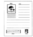
図2に示す書類画像のレイアウトの例を使って説明する。
画像A、画像B、画像Cは、図示されているように中サイズ、小サイズ、横長の画像を表す。また、図2の横線は文章を表す。画像A、画像Bについては縦または横幅のサイズを判断することで、切り換えを行う。
この図2の場合、画像Aは縦横同程度なのでどちらで判断してもかまわないが、画像Bは小サイズであるので画像空間周波数を高くするように切り換える。
画像Cは、横長の画像であるから特に覗き込むことはなく画像Aと同様の処理でかまわないと思われるが、画像Bと同様の処理であってもかまわない。
また、縦長の画像である場合に、経験上、横長の画像よりも覗き込むことが多いと思われるので、総合的に判断する場合に縦横どちらをみてもかまわないが、横幅をみる方がより適当である。
【0014】
(ロ)画像サイズの縦横方向の大きさにより画像空間周波数の選択を行う。
例えば、画像の縦幅をT、横幅をYとして、(T+Y)を選択のパラメータとする。また、(イ)で述べた縦長、横長の画像の判断をするために、縦横のサイズの比較を行い、より小さい方を用いて切り換えの判断を行なうようにしてもよい。
(ハ)画像の面積により画像空間周波数の選択を行う。
画像の縦幅をT、横幅をYとして、(T*Y)を選択のパラメータとする。
(ニ)画像サイズと視認距離の関係を考慮して決定する。
図3に示されるように、通常の視認距離をbとし、これに対し覗き込んだときの距離をaとすると、aはbの半分程度と思われる。
また、一般に視認距離は35センチとすることが多いので、用紙サイズがA4サイズ程度であれば、切り換え点は、画像内容にもよるが切手サイズ程度(2センチ乃至3センチ)と思われる。
本実施例では切り換え点のサイズを3センチとする。なお、本実施例の上記ディザ線数とこの切り換え点の設定は視覚特性から考慮されたものであり、ディザ線数と切り換え点の設定はこれ以外でも構わない。
ここで視覚特性(視覚の空間周波数特性(MTF))は、図4に示すように、観察距離350mmにおける画像周波数に対する人間の視覚感度:VTF(Visual Transfer Function)と呼ばれ、VTFを使った技術に特開平10−23191号等がある。)として知られている。図4によると、画像の周波数が高周波になるにつれて感度が低下し、8cycle/mm(200Line/inch)以上ではかなり低いレベルとなり、250Line/inchではまったく認知できなくなっている。
一方、観察距離が変わればこの視覚特性もその距離に比例するように変化しており、観察距離が半分の175mmになれば上記の倍の画像空間周波数までその画像の基調が認識される。
【0015】
(ホ)出力用紙サイズにより画像空間周波数の切り換えを行う。
出力サイズ取得手段130で得た出力用紙のサイズが、A4サイズ以下では223線で処理し、A4サイズより大きければ112線で処理する等とする。
また、上述した画像サイズとこの出力用紙サイズとを用いて画像空間周波数を切り換えるようにしてもよい。例えば、切り換え画像サイズをA4サイズ以下では3センチとするが、ポスターのようにA4サイズより大きければ5センチとし、それぞれ223線/112線で切り換える。
(へ)同一ページ内にある複数の画像の画像空間周波数は同一にする。
出力時にページの始めと終わりの間に送られてきた画像データのサイズを調べ、その中の一つに注目(例えば、画像サイズのうち大/中/小のいずれか)して画像空間周波数を決定する。
(ト)同一ファイル内にある複数の画像の画像空間周波数は同一にする。
出力時に同一ファイルであることを確認し、その中で画像サイズを調べ、(ヘ)と同様にして画像空間周波数を決定する。
または、ファイル情報として画像サイズを予め記録しておいて、それを取得するようにしてもよい。
【0016】
(チ)画像空間周波数の切り換えに用いる複数のスクリーンの基調または方向性を同一とする。
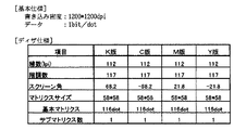
本実施例で扱う中間調処理のディザ法は、YMCK(イエロー、マゼンタ、シアン、ブラック)各色の画像の基調がライン状となり、さらにそのライン方向性が各色で異なる万線スクリーン角ディザとしている。この各色の万線スクリーン各方向は、図5に示すように構成しており、この万線スクリーン角ディザは、1200*1200dpi/1bit書き込みにおける高線数スクリーン角ディザの仕様(図6参照)と低線数スクリーン角ディザの仕様(図7参照)で、これら2つのディザマトリクスでは画像形成の画像空間周波数が異なるが、その他、スクリーン角方向などは共通にし、その基調もライン状で同じにすることによって、ライン画像によるドット集中で安定な画像が形成され、スクリーン角による版ずれに対する色ムラ低減が図られる。
また、一般的な円状にドットを集中させた網点型のディザでも、本発明と同様に展開できる。
【0017】
(3)切替方法の多段階化
また、これらの切り替える段階を多段階とすることでより的確な切り替えを行うことができる。例えば、画像サイズを判定することにより、予め用意した複数のディザパターンの中から最適なものを選択することにより、より精度の高い出力画像を得ることができる。
例えば、100、150、200線のディザがあり、出力画像サイズ15センチ以上、3センチ以下で切り替える。この場合は、紙面上の大きさで言えば、出力解像度が1200dpiであれば、(15/2.54)*1200=7086ドット以上、(3/2.54)*1200=1417ドット以下で判断することになる。
尚、本発明における画像形成の空間周波数の切り換えにはその操作が容易なディザ法により実施しているが、画像サイズに基づき誤差拡散法など他の中間調処理法で画像形成の空間周波数特性を異ならせても構わない。
【0018】
このように実施例を構成することによって、以下の効果が発揮される。
出力画像の大きさに基づいて画像空間周波数を切り替えることにより出力画像の大きさごとの安定な画像の実現と視覚的な各要求項目のバランスをとることができる。
すなわち、出力画像の大きさに基づいた画像空間周波数の切り替えを行い、大きい画像は離して見るので低線数で高安定にし、切手サイズのような小さい画像は覗き込んで見るので高線数にて処理することができる。
画像空間周波数の切り替えを多段階に行うことによって視覚的な要求に対してより最適に、画像空間周波数の選択が行える。
人の視覚特性を加味することで視覚的な要求に対するバランスがより的確にできる。
イメージサイズの特徴に着目することでより的確な切り換え処理ができる。
同一ページ内にある複数の画像に対しては画像空間周波数を同じにすることでより的確に処理ができる。
同一ファイル内にある複数の画像に対しては画像空間周波数を同じにすることでより的確に処理ができる。
画像空間周波数の切り替えの選択(切り替えをしないことも含めて)ができるため自由度が向上する。
複数のスクリーンの基調を同一とすることで、異なった処理を行った場合に発生する可能性のある視覚的な違和感をなくすことができる。
複数のスクリーンの方向性を同一とすることで、異なった処理を行った場合に発生する可能性のある視覚的な違和感をなくすことができる。
出力用紙サイズによって画像空間周波数を切り換えているため、ポスターのように大きな用紙は離れて見るため低線数で安定にし、小さな用紙であるときは高線数とすることで安定かつ十分な画像が得られる。
出力画像サイズと出力用紙サイズの両方を考慮しているため、より視覚的に良好な画像が得られる。
【0019】
(4)実施例の処理の流れ
図8は、本実施例の処理の流れを示すフローチャートである。
コンピュータのアプリケーション等から出力する画像データとその出力命令および出力する用紙のサイズとを指定して画像を出力させ、この出力命令を受けた本装置は、次のように動作する。
送られてきたテキスト、グラフィックスまたはイメージデータを画像データとして取り込み(ステップS100)、カラー調整を行う(ステップS110)。取得したデータの種類に応じてそれぞれの処理が行われる(ステップS120)。
データがグラフィックスの場合には、ラスタライズして(ステップS130)、ステップS140へ進む。
また、データがテキストの時には、墨生成/下色除去し、総量規制、エンジンガンマによる濃度調整を行い(ステップS180)、ディザ/誤差拡散の処理を行って、出力装置の特性に適合するようにデータ変換を行い(ステップS190)、ステップS170へ進む。
また、イメージデータのときは、ステップS140へ進む。
ステップS140では、画像データのサイズ(縦横方向の大きさ)および出力用紙のサイズ等を取得する。
次に、画像データは、墨生成/下色除去し、総量規制、エンジンガンマによる濃度調整を行い、拡大縮小処理を行う(ステップS150)。
ステップS140で取得したサイズに基づいて((2)および(3)参照)、線数を切り換えてディザ/誤差拡散の処理を行って、出力装置の特性に適合するようにデータ変換を行い(ステップS160)、ステップS170へ進む。
ステップS170では、中間調処理されたオブジェクトを出力用紙にあわせてレイアウト処理を行う。
これまでのステップS100からS170までを、1ページ分の画像データが処理されるまで繰り返し、1ページが完成すると実際の出力が行われる。
これをすべての画像データが終了するまで繰り返すことによって、アプリケーションプログラムから命令された出力処理が終了する。
尚、本発明は上記の実施の形態のみに限定されたものではない。
上述した実施の形態の機能を実現する画像形成装置を構成する各機能をそれぞれプログラム化し、予めROM等の記録媒体に書き込んでおき、それを実行することによって、本発明の目的を達成することができる。
【0020】
【発明の効果】
以上のように本発明によれば、出力画像の大きさに対する安定な画像と視覚的な要求のバランスをとり、画像空間周波数の最適な選択を行うことができる。
【図面の簡単な説明】
【図1】本発明の画像形成装置の構成を示すブロック図である。
【図2】書類画像のレイアウト例を示す図である。
【図3】視認距離を説明するための模式図である。
【図4】視覚特性を表すグラフ図である。
【図5】万線スクリーン角方向を説明するための模式図である。
【図6】1200×1200dpi高線数ディザ仕様を示す表図である。
【図7】1200×1200dpi低線数ディザ仕様を示す表図である。
【図8】本発明の画像形成装置の処理の流れを説明するためのフローチャートである。
【符号の説明】
110 画像取得手段
120 画像サイズ取得手段
130 出力サイズ取得手段
140 切替手段
150 切替方法設定手段
160 画像処理手段
170 中間調処理手段
180 レイアウト手段[0001]
BACKGROUND OF THE INVENTION
The present invention relates to an image forming apparatus, an image forming method, and a recording medium that perform optimal image processing on an input image. Specifically, the present invention relates to an image forming apparatus, an image forming method, and a recording medium that optimally select an image spatial frequency of an output image.
[0002]
[Prior art]
A dither method is known as a technique for halftone processing of input image data. This dither method uses a threshold (dither) matrix composed of a plurality of threshold values for a plurality of input image data, and binarizes the input image data as black when the input image data is larger than this threshold, and as white when the input image data is smaller. The image can be reproduced.
However, even if the resolution of the input image data changes, halftone processing is performed using the same threshold matrix, so the pitch of the output image changes depending on the resolution, and the image quality changes greatly after processing, and the input image May not be faithfully reproduced.
The technology of Japanese Patent No. 2832052 solves this problem, and even for input images with different resolutions, different dithers are prepared for each resolution so that the results are the same, so that the difference in the visual difference is obtained. It is to obtain fewer images. There are SPC method, logical sum method, nine-division division method, high-speed projection method, distance inverse proportional method, etc. as the enlargement / reduction method used for characters, line drawings, etc. When these enlargement / reduction methods are applied to dither images, The gradation information of the image is lost or moire fringes are generated, leading to degradation of image quality. Therefore, the original pixel group in the vicinity region of the conversion pixel obtained by position conversion is selected as a reference pixel, and the density of the conversion pixel is obtained from the binarization pattern of the selected reference pixel and binarized by systematic dither. There is a technique (for example, Japanese Patent Application Laid-Open No. 62-216476) that executes dither image enlargement / reduction in accordance with a method of doing so.
[0003]
In the technique disclosed in Japanese Patent Laid-Open No. 62-216476, when conversion pixels are obtained by position conversion processing corresponding to a specified conversion magnification, an original pixel group is selected as a reference pixel for each conversion pixel, The number of black pixels among the reference pixels is specified as the density of the conversion pixel, and the dither image is enlarged or reduced by binarizing the obtained density of the conversion pixel by systematic dither.
However, the use of the technique disclosed in Japanese Patent Application Laid-Open No. Sho 62-216476 is intended to improve the problem of image quality degradation caused by the application of the SPC method or the like for enlargement / reduction of dithered images. However, in the enlargement process, conversion pixels that use the same original pixel group as reference pixels are treated as having the same density, so that the edge portion included in the dithered image of the original image is blurred. The problem that it will end up comes out.
In order to solve this problem, in the technique of Japanese Patent No. 2899304, the dither image generated according to the systematic dither is selectively used as the second dither process serving as an opening with respect to the first dither process image. By doing so, the degradation of image quality associated with the enlargement / reduction processing is solved.
[0004]
In general, each operation target (also referred to as an object) such as a bitmap image image, characters including character information and modification information such as character size and font, and coordinates information and modification information input using a pointing device. The document is laid out on a single document, each attribute information is manipulated / edited, and the manipulated / edited document is printed out by a printing apparatus.
When this printout is performed, a resize process such as a complement process or a thinning process is performed so that the layout / print image information fits a predetermined print output size, and a print image is generated. In addition, for characters and figures, bitmap character print character information is generated at a resolution required for print output based on the outline data after layout. A desired print image and print characters are synthesized by using the bitmap image with the resized image and the generated characters.
For this reason, when layout and print output on a document are performed, conventionally, necessary layout / print image information is stored in the document. Therefore, layout and print output are performed according to this information. In addition, once the image is read, it is not necessary to read image data like an image scanner.
[0005]
However, since the information on the characters and graphics among the operation objects held on the document is shape definition information and attribute information such as color and fill, the information storage capacity may be small, but information on the bitmap image image is Since the information is in units of pixels, the information storage capacity is significantly larger than that of characters and figures.
In addition, information about characters and graphics must be retained in the document because the shape definition information is only changed in accordance with the change rate of the print output size even if the size is changed on the document or during print output. The amount of information does not change.
On the other hand, the bitmap image information of the image decreases the resolution of the bitmap image and decreases the image quality when the size of the print output increases, because the size of the bitmap image is adjusted by the complementary processing. I was sorry. In order to prevent such deterioration in image quality, it is necessary to determine the size of the bitmap image for document printing in advance according to the print output size. If read in, even in the layout work on the computer screen, which is irrelevant to the print output size, the large size image must be handled, and the screen update and layout work will be significantly slowed down, making it quick. If the layout work is to be performed, a larger capacity memory and a high-speed CPU are required.
In order to solve this problem, the technique disclosed in Japanese Patent Laid-Open No. 2000-76472 uses an image read at a low resolution for layout, and at the time of print output, the original image information and the print output size when read at a low resolution. Based on the information, an optimum reading resolution for print output is set, and the image is read again by the image reading means at this resolution and printed out.
[0006]
[Problems to be solved by the invention]
In general, when viewing one image, the image has a certain width (viewing angle). When viewing a small image, the viewing distance is reduced (for example, an image at a distance a in FIG. 3), and a large image is displayed. The viewing distance is set large to see the whole (for example, an image at a distance b in FIG. 3).
Also, depending on the type of pattern to be noticed, for example, a required image spatial frequency differs between a human face and a simple figure or a solid color.
On the other hand, when the performance of the image forming apparatus such as electrophotography affects the image quality, the image quality may be more stable when the number of lines is lower than when it is higher.
Specifically, a processing method is generally used in which the number of lines is reduced to improve the graininess and uniformity, and the number of lines is increased to improve the sharpness.
However, in the conventional method described above, the relationship between the size of the output image and the viewing distance is not taken into consideration, and thus there is a problem that the quality of the output image is not sufficient with respect to the viewing distance. It was.
The present invention has been made in consideration of the above points, and an image forming apparatus and an image forming apparatus that perform an optimal selection of an image spatial frequency by balancing a stable image and a visual requirement with respect to the size of an output image. It is an object to provide a forming method and a recording medium.
[0007]
[Means for Solving the Problems]
The image forming apparatus according to
According to a second aspect of the present invention, the halftone processing means performs halftone processing at an image spatial frequency based on a size of one side of the image size.
According to a third aspect of the present invention, the halftone processing means performs halftone processing at an image spatial frequency based on the vertical and horizontal sizes of the image size.
According to a fourth aspect of the present invention, the halftone processing means performs halftone processing at an image spatial frequency corresponding to the area of the image in the image data.
The image forming apparatus according to claim 5 of the present invention includes an acquisition unit that acquires image data and an output command output from an application, a size acquisition unit that calculates a size of a recording medium based on the output command, Based on the image processing means for performing image processing on the image data, the switching means for switching the image spatial frequency according to the size of the recording medium calculated by the size acquisition means, and the image based on the image spatial frequency switched by the switching means Halftone processing means for performing halftone processing on the processed image data,The halftone processing means examines the image size of a plurality of image data in the same page or the same file, determines an image spatial frequency by paying attention to a predetermined image size in the image data, and in the same page or the same file. The image spatial frequencies of multiple image data are the sameIt is characterized by that.
According to a sixth aspect of the present invention, the switching means switches the image spatial frequency in multiple stages.
And features.
[0008]
According to a seventh aspect of the present invention, there is provided an image forming method according to the present invention, wherein the image processing is performed based on an image data acquisition step, an image processing step on the image data, and an image spatial frequency corresponding to an image size of the image data. Applying halftone processing to the processed image data.And performing the halftone process includes examining the image sizes of a plurality of image data in the same page or the same file, determining an image spatial frequency by paying attention to a predetermined image size therein, and The image spatial frequency of multiple image data in a page or the same file is the sameIt is characterized by that.
According to an eighth aspect of the present invention, the step of applying halftone processing performs halftone processing at an image spatial frequency based on a size of one side of the image size.
According to a ninth aspect of the present invention, the step of applying halftone processing performs halftone processing at an image spatial frequency based on the vertical and horizontal sizes of the image size.
According to a tenth aspect of the present invention, the step of applying halftone processing performs halftone processing at an image spatial frequency corresponding to the area of the image in the image data.
An image forming method according to an eleventh aspect of the present invention includes a step of acquiring image data and an output command output from an application, a step of calculating a size of a recording body based on the output command, and an image process on the image data. A step of switching the image spatial frequency in accordance with the calculated size of the recording medium, and a step of applying halftone processing to the image processed image data based on the switched image spatial frequency. AndThe step of performing the halftone processing is to examine the image size of a plurality of image data in the same page or the same file, determine an image spatial frequency by paying attention to a predetermined image size in the image data, and to perform the same page or the same The image spatial frequency of multiple image data in the file is the sameIt is characterized by that.
According to a twelfth aspect of the present invention, the step of switching the image spatial frequency switches the image spatial frequency in multiple stages.
[0009]
A computer-readable recording medium according to a thirteenth aspect of the present invention is a computer-readable recording medium storing a program for causing a computer to execute the processing function of the image forming apparatus according to any one of the first to sixth aspects. It is a recording medium.
A computer-readable recording medium according to a fourteenth aspect of the present invention is a computer-readable recording in which a program for causing a computer to execute the image forming method according to any one of the seventh to twelfth aspects is recorded. It is a medium.
[0010]
DETAILED DESCRIPTION OF THE INVENTION
Hereinafter, the configuration and operation of the present invention will be described with reference to the drawings.
(1) Functional configuration of the embodiment
FIG. 1 is a functional block diagram of the image forming apparatus of the present invention.
The apparatus includes an
First, an image is output by designating image data to be output from a computer application or the like, its output command, and the size of paper to be output. Receiving this output command, this apparatus operates roughly as follows.
The
-Capture images as an image from an input device such as a scanner.
• Read image data that has already been imported from a file.
Receive image data from other computers connected to the network.
• Import from an application program that outputs text, graphics, or images.
This image data is given as coordinates in the paper, that is, position data (start point, horizontal width, vertical width: dots), data for determining the output size (resolution, scaling factor, etc.) and original image data.
[0011]
The image data captured by the
The
The
When the image data captured by the
The image
Further, in the case where the output size is used as a condition for switching directly, the image data is not received from the
When the image data is graphics, the same processing can be performed by performing rasterization and then sending the image data to the image size acquisition means 120.
On the other hand, the output
[0012]
The
For example, if the output image size for switching the number of lines is 5 centimeters, and the output image is 1200 dpi, (5 / 2.54) * 1200 = about 2362 dots is the size of the paper surface, and the dots of the output target image When the size is larger than that, the halftone processing is performed with 112 lines, and when the size is smaller, 223 lines are used.
In addition, the switching
[0013]
(2) Image spatial frequency switching method
The
(A) The image spatial frequency is selected according to the size of one side of the image size.
In addition to judging only the vertical or horizontal width, the overall judgment is made by looking at the long side of the rectangle or the short side, taking into account visual characteristics (see below).
A description will be given using an example of the layout of the document image shown in FIG.
Image A, image B, and image C represent medium, small, and horizontally long images as shown in the figure. Moreover, the horizontal line of FIG. 2 represents a sentence. The image A and the image B are switched by determining the vertical or horizontal size.
In the case of FIG. 2, the image A is approximately the same in both the vertical and horizontal directions, and either may be determined. However, since the image B is a small size, the image spatial frequency is switched to be increased.
Since the image C is a horizontally long image, the image C is not particularly looked into and may be processed in the same manner as the image A, but may be processed in the same manner as the image B.
In addition, in the case of a portrait image, it seems that there is more to look into than a landscape image in experience, so if you make a comprehensive judgment, you can see either portrait or landscape, but it is better to look at the width Is appropriate.
[0014]
(B) The image spatial frequency is selected according to the vertical and horizontal sizes of the image size.
For example, assume that the vertical width of the image is T, the horizontal width is Y, and (T + Y) is a selection parameter. Further, in order to determine the portrait or landscape image described in (a), the comparison between the portrait and landscape sizes may be performed, and the switching determination may be performed using the smaller one.
(C) The image spatial frequency is selected according to the area of the image.
The vertical width of the image is T, the horizontal width is Y, and (T * Y) is a selection parameter.
(D) Determined in consideration of the relationship between the image size and the viewing distance.
As shown in FIG. 3, when the normal viewing distance is b and the distance when looking into this is a, a seems to be about half of b.
In general, the viewing distance is often 35 cm. Therefore, if the paper size is about A4 size, the switching point is considered to be about the stamp size (2 cm to 3 cm) depending on the image content.
In this embodiment, the size of the switching point is 3 cm. Note that the setting of the number of dither lines and the switching point in the present embodiment is considered in view of visual characteristics, and the setting of the number of dither lines and the switching point may be other than this.
Here, the visual characteristic (visual spatial frequency characteristic (MTF)) is called a human visual sensitivity (VTF (Visual Transfer Function) with respect to an image frequency at an observation distance of 350 mm, as shown in FIG. 4, and is a technique using VTF. JP-A-10-23191 and the like. ). According to FIG. 4, the sensitivity decreases as the frequency of the image becomes higher, the level is considerably lower at 8 cycle / mm (200 Line / inch) or higher, and it cannot be recognized at 250 Line / inch at all.
On the other hand, if the observation distance changes, this visual characteristic also changes in proportion to the distance, and if the observation distance becomes half of 175 mm, the basic tone of the image is recognized up to the double image spatial frequency.
[0015]
(E) The image spatial frequency is switched according to the output paper size.
If the output paper size obtained by the output size acquisition means 130 is A4 size or less, processing is performed with 223 lines, and if it is larger than A4 size, processing is performed with 112 lines.
Further, the image spatial frequency may be switched using the image size described above and the output paper size. For example, if the switching image size is 3 centimeters or less for the A4 size or less, the switching image size is 5 centimeters if it is larger than the A4 size as in the poster, and switching is performed at 223 lines / 112 lines, respectively.
(F) The image spatial frequencies of a plurality of images in the same page are the same.
Check the size of the image data sent between the beginning and end of the page at the time of output, and pay attention to one of them (for example, one of large / medium / small among the image sizes) and set the image spatial frequency. decide.
(G) The image spatial frequencies of a plurality of images in the same file are the same.
At the time of output, it is confirmed that they are the same file, the image size is checked in the file, and the image spatial frequency is determined in the same manner as (f).
Alternatively, the image size may be recorded in advance as file information and acquired.
[0016]
(H) The basic tone or directionality of a plurality of screens used for switching the image spatial frequency is the same.
The dither method of halftone processing handled in this embodiment is a line screen angle dither in which the basic tone of each image of YMCK (yellow, magenta, cyan, black) is a line, and the line directionality is different for each color. Each direction of the line screen of each color is configured as shown in FIG. 5. This line screen angle dither is the same as the specifications of the high line number screen angle dither in 1200 * 1200 dpi / 1 bit writing (see FIG. 6). With the specifications of low-line-number screen angle dither (see FIG. 7), the image spatial frequency of image formation differs between these two dither matrices, but the screen angle direction is the same, and the basic tone is the same in a line shape. As a result, a stable image is formed with dot concentration by the line image, and color unevenness is reduced with respect to plate misregistration due to the screen angle.
Further, even a general dot-type dither in which dots are concentrated in a circular shape can be developed in the same manner as in the present invention.
[0017]
(3) Multi-stage switching method
Moreover, more accurate switching can be performed by making these switching stages into multiple stages. For example, it is possible to obtain an output image with higher accuracy by determining an image size and selecting an optimum one from a plurality of dither patterns prepared in advance.
For example, there are 100, 150, and 200 line dithers, and the output image size is switched between 15 cm and 3 cm. In this case, in terms of the size on the paper surface, if the output resolution is 1200 dpi, it is determined that (15 / 2.54) * 1200 = 7086 dots or more and (3 / 2.54) * 1200 = 1417 dots or less. Will do.
It should be noted that the switching of the spatial frequency of image formation in the present invention is performed by a dither method that is easy to operate, but the spatial frequency characteristics of the image formation can be changed by other halftone processing methods such as an error diffusion method based on the image size. You can make them different.
[0018]
By configuring the embodiment in this way, the following effects are exhibited.
By switching the image spatial frequency based on the size of the output image, it is possible to achieve a stable image for each size of the output image and balance each visual requirement item.
In other words, the image spatial frequency is switched based on the size of the output image, and the large image is viewed at a distance so that it is highly stable at a low line number. Can be processed.
By switching the image spatial frequency in multiple stages, the image spatial frequency can be selected more optimally for the visual demand.
By taking into account human visual characteristics, the balance with respect to visual requirements can be made more accurate.
By focusing on the characteristics of the image size, more accurate switching processing can be performed.
A plurality of images in the same page can be processed more accurately by making the image spatial frequency the same.
A plurality of images in the same file can be processed more accurately by using the same image spatial frequency.
Since it is possible to select switching (including no switching) of the image spatial frequency, the degree of freedom is improved.
By making the fundamentals of the plurality of screens the same, it is possible to eliminate visual discomfort that may occur when different processes are performed.
By making the directions of the plurality of screens the same, it is possible to eliminate visual discomfort that may occur when different processes are performed.
Since the image spatial frequency is switched according to the output paper size, a large paper like a poster can be seen at a distance, so it can be stabilized with a low number of lines. can get.
Since both the output image size and the output paper size are taken into consideration, a visually better image can be obtained.
[0019]
(4) Process flow of the embodiment
FIG. 8 is a flowchart showing the flow of processing of this embodiment.
An image is output by designating image data to be output from a computer application or the like, an output command thereof, and a paper size to be output, and the apparatus that receives the output command operates as follows.
The sent text, graphics or image data is captured as image data (step S100), and color adjustment is performed (step S110). Each process is performed according to the kind of acquired data (step S120).
If the data is graphics, it is rasterized (step S130) and the process proceeds to step S140.
When the data is text, black generation / undercolor removal, total amount regulation, density adjustment by engine gamma are performed (step S180), and dither / error diffusion processing is performed so as to conform to the characteristics of the output device. Data conversion is performed (step S190), and the process proceeds to step S170.
If it is image data, the process proceeds to step S140.
In step S140, the image data size (size in the vertical and horizontal directions), the size of the output paper, and the like are acquired.
Next, the image data is subjected to black generation / undercolor removal, total amount regulation, density adjustment by engine gamma, and enlargement / reduction processing (step S150).
Based on the size obtained in step S140 (see (2) and (3)), dither / error diffusion processing is performed by switching the number of lines, and data conversion is performed so as to conform to the characteristics of the output device (step S160), the process proceeds to step S170.
In step S170, the layout processing is performed on the halftone processed object in accordance with the output paper.
Steps S100 to S170 are repeated until one page of image data is processed, and when one page is completed, actual output is performed.
By repeating this until all the image data is finished, the output process instructed by the application program is finished.
Note that the present invention is not limited to the above-described embodiment.
It is possible to achieve the object of the present invention by programming each function that constitutes the image forming apparatus that realizes the functions of the above-described embodiments, writing in advance on a recording medium such as a ROM, and executing the program. it can.
[0020]
【The invention's effect】
As described above, according to the present invention, it is possible to optimally select an image spatial frequency by balancing a stable image and a visual requirement with respect to the size of an output image.
[Brief description of the drawings]
FIG. 1 is a block diagram illustrating a configuration of an image forming apparatus of the present invention.
FIG. 2 is a diagram illustrating a layout example of a document image.
FIG. 3 is a schematic diagram for explaining a viewing distance.
FIG. 4 is a graph showing visual characteristics.
FIG. 5 is a schematic diagram for explaining a line screen angular direction.
FIG. 6 is a table showing a 1200 × 1200 dpi high line number dither specification.
FIG. 7 is a table showing a 1200 × 1200 dpi low line number dither specification.
FIG. 8 is a flowchart for explaining a processing flow of the image forming apparatus of the present invention.
[Explanation of symbols]
110 Image acquisition means
120 Image size acquisition means
130 Output size acquisition means
140 switching means
150 switching method setting means
160 Image processing means
170 Halftone processing means
180 Layout means
Claims (14)
前記画像データに画像処理を施す画像処理手段と、
前記画像データの画像サイズに応じた画像空間周波数に基づいて、当該画像処理された画像データに中間調処理を施す中間調処理手段とを有し、
前記中間調処理手段は、同一ページあるいは同一ファイル内の複数の画像データの画像サイズを調べ、その中の所定の画像サイズに注目して画像空間周波数を決定して、当該同一ページあるいは同一ファイル内の複数の画像データの画像空間周波数は同一にすることを特徴とする画像形成装置。Acquisition means for acquiring image data;
Image processing means for performing image processing on the image data;
Halftone processing means for performing halftone processing on the image data that has been subjected to the image processing based on the image spatial frequency according to the image size of the image data ;
The halftone processing means examines the image size of a plurality of image data in the same page or the same file, determines an image spatial frequency by paying attention to a predetermined image size in the image data, and in the same page or the same file. An image forming apparatus characterized in that the plurality of image data have the same image spatial frequency .
前記出力命令に基づいて記録体のサイズを算出するサイズ取得手段と、
前記画像データに画像処理を施す画像処理手段と、
前記サイズ取得手段で算出した記録体のサイズに応じて画像空間周波数を切り替える切替手段と、
前記切替手段で切り替えた画像空間周波数に基づいて、当該画像処理された画像データに中間調処理を施す中間調処理手段とを有し、
前記中間調処理手段は、同一ページあるいは同一ファイル内の複数の画像データの画像サイズを調べ、その中の所定の画像サイズに注目して画像空間周波数を決定して、当該同一ページあるいは同一ファイル内の複数の画像データの画像空間周波数は同一にすることを特徴とする画像形成装置。Acquisition means for acquiring image data and output commands output from the application;
Size acquisition means for calculating the size of the recording body based on the output command;
Image processing means for performing image processing on the image data;
Switching means for switching the image spatial frequency according to the size of the recording medium calculated by the size acquisition means;
Based on the image spatial frequency is switched by the switching means, and a halftone processing unit that performs halftone processing on the image processed image data,
The halftone processing means examines the image size of a plurality of image data in the same page or the same file, determines an image spatial frequency by paying attention to a predetermined image size in the image data, and in the same page or the same file. An image forming apparatus characterized in that the plurality of image data have the same image spatial frequency .
前記画像データに画像処理を施すステップと、
前記画像データの画像サイズに応じた画像空間周波数に基づいて、当該画像処理された画像データに中間調処理を施すステップとを有し、
前記中間調処理を施すステップは、同一ページあるいは同一ファイル内の複数の画像データの画像サイズを調べ、その中の所定の画像サイズに注目して画像空間周波数を決定して、当該同一ページあるいは同一ファイル内の複数の画像データの画像空間周波数は同一にすることを特徴とする画像形成方法。Obtaining image data; and
Applying image processing to the image data;
Based on the image space frequency corresponding to the image size of the image data, and a step of performing a halftone process on the processed image data,
The step of performing the halftone processing is to examine the image size of a plurality of image data in the same page or the same file, determine an image spatial frequency by paying attention to a predetermined image size in the image data, and to perform the same page or the same An image forming method, wherein the image spatial frequencies of a plurality of image data in a file are the same .
前記出力命令に基づいて記録体のサイズを算出するステップと、
前記画像データに画像処理を施すステップと、
前記算出した記録体のサイズに応じて画像空間周波数を切り替えるステップと、
前記切り替えた画像空間周波数に基づいて、当該画像処理された画像データに中間調処理を施すステップとを有し、
前記中間調処理を施すステップは、同一ページあるいは同一ファイル内の複数の画像データの画像サイズを調べ、その中の所定の画像サイズに注目して画像空間周波数を決定して、当該同一ページあるいは同一ファイル内の複数の画像データの画像空間周波数は同一にすることを特徴とする画像形成方法。Obtaining image data and output instructions output from the application;
Calculating the size of the recording body based on the output command;
Applying image processing to the image data;
Switching the image spatial frequency in accordance with the calculated size of the recording medium;
Based on the switched image spatial frequency, and a step of performing a halftone process on the processed image data,
The step of performing the halftone processing is to examine the image size of a plurality of image data in the same page or the same file, determine an image spatial frequency by paying attention to a predetermined image size in the image data, and to perform the same page or the same An image forming method, wherein the image spatial frequencies of a plurality of image data in a file are the same .
Priority Applications (2)
| Application Number | Priority Date | Filing Date | Title |
|---|---|---|---|
| JP2001077282A JP4089862B2 (en) | 2001-03-16 | 2001-03-16 | Image forming apparatus, image forming method, and recording medium |
| US10/095,473 US7315402B2 (en) | 2001-03-16 | 2002-03-13 | Image forming apparatus and method for selecting an optimal image space frequency for an output image |
Applications Claiming Priority (1)
| Application Number | Priority Date | Filing Date | Title |
|---|---|---|---|
| JP2001077282A JP4089862B2 (en) | 2001-03-16 | 2001-03-16 | Image forming apparatus, image forming method, and recording medium |
Publications (3)
| Publication Number | Publication Date |
|---|---|
| JP2002281306A JP2002281306A (en) | 2002-09-27 |
| JP2002281306A5 JP2002281306A5 (en) | 2005-09-29 |
| JP4089862B2 true JP4089862B2 (en) | 2008-05-28 |
Family
ID=18934063
Family Applications (1)
| Application Number | Title | Priority Date | Filing Date |
|---|---|---|---|
| JP2001077282A Expired - Fee Related JP4089862B2 (en) | 2001-03-16 | 2001-03-16 | Image forming apparatus, image forming method, and recording medium |
Country Status (2)
| Country | Link |
|---|---|
| US (1) | US7315402B2 (en) |
| JP (1) | JP4089862B2 (en) |
Families Citing this family (9)
| Publication number | Priority date | Publication date | Assignee | Title |
|---|---|---|---|---|
| JP4014083B2 (en) | 2002-03-06 | 2007-11-28 | 株式会社リコー | Image forming apparatus |
| JP2005027109A (en) * | 2003-07-03 | 2005-01-27 | Ricoh Co Ltd | Color image formation device and method |
| JP4801489B2 (en) * | 2006-04-20 | 2011-10-26 | 株式会社リコー | Image forming apparatus and image forming program |
| JP4506847B2 (en) * | 2008-02-08 | 2010-07-21 | ソニー株式会社 | Tone modulation apparatus, image processing apparatus, image processing method, and program |
| JP5241429B2 (en) * | 2008-10-24 | 2013-07-17 | キヤノン株式会社 | Image forming apparatus and control method thereof |
| JP5254739B2 (en) * | 2008-10-24 | 2013-08-07 | キヤノン株式会社 | Image forming apparatus and control method thereof |
| JP5685944B2 (en) * | 2011-01-12 | 2015-03-18 | 株式会社リコー | Image processing apparatus and image forming apparatus |
| JP7263892B2 (en) * | 2019-04-04 | 2023-04-25 | コニカミノルタ株式会社 | IMAGE FORMING APPARATUS, PRINT SETTING CHANGE METHOD AND PRINT SETTING CHANGE PROGRAM |
| JP2021000763A (en) | 2019-06-21 | 2021-01-07 | 株式会社リコー | Head drive device, liquid ejection device and head drive method |
Family Cites Families (10)
| Publication number | Priority date | Publication date | Assignee | Title |
|---|---|---|---|---|
| JPS59111471A (en) * | 1982-12-17 | 1984-06-27 | Ricoh Co Ltd | Picture processor |
| US5321523A (en) * | 1988-03-11 | 1994-06-14 | Canon Kabushiki Kaisha | Image processing apparatus |
| JP2899304B2 (en) | 1989-03-20 | 1999-06-02 | 富士通株式会社 | Dither image scaling processor |
| JP2832052B2 (en) * | 1989-12-28 | 1998-12-02 | キヤノン株式会社 | Image processing device |
| US5471543A (en) * | 1990-06-25 | 1995-11-28 | Eastman Kodak Company | Mixed screen frequencies with image segmentation |
| JPH0777418A (en) | 1993-06-15 | 1995-03-20 | Takasago Ind Co Ltd | Identification method for baked tile or tile base material |
| JPH09114443A (en) * | 1995-10-20 | 1997-05-02 | Seiko Epson Corp | Video scaling device |
| US6002804A (en) * | 1998-03-26 | 1999-12-14 | Hewlett-Packard Company | Tone dependent variable halftoning with adjustable algorithm selection |
| US6055065A (en) * | 1998-08-12 | 2000-04-25 | International Business Machines Corporation | Printer independent halftone image rendering |
| JP2000076472A (en) | 1998-08-31 | 2000-03-14 | Fuji Photo Film Co Ltd | Program storage medium |
-
2001
- 2001-03-16 JP JP2001077282A patent/JP4089862B2/en not_active Expired - Fee Related
-
2002
- 2002-03-13 US US10/095,473 patent/US7315402B2/en not_active Expired - Fee Related
Also Published As
| Publication number | Publication date |
|---|---|
| US7315402B2 (en) | 2008-01-01 |
| US20020131061A1 (en) | 2002-09-19 |
| JP2002281306A (en) | 2002-09-27 |
Similar Documents
| Publication | Publication Date | Title |
|---|---|---|
| JP4610802B2 (en) | Gray level image edge enhancement | |
| US7463389B2 (en) | Image processing method, image processing device and program | |
| US6760489B1 (en) | Apparatus and method for image data interpolation and medium on which image data interpolation program is recorded | |
| JPH10108022A (en) | Method and device for acquiring halftone image data and halftone printing method and device | |
| JPH11272252A (en) | Process for removing half-tone from digital image | |
| JP7005314B2 (en) | Image processing equipment, image processing methods, and programs | |
| JPH11154226A (en) | Method and device for improving resolution | |
| JP4089862B2 (en) | Image forming apparatus, image forming method, and recording medium | |
| JP3765847B2 (en) | Pixel correction and smoothing method | |
| JP5202281B2 (en) | Image processing apparatus and image processing method | |
| US7315398B2 (en) | Multi-level error diffusion with color image data | |
| CN101346981B (en) | Image processing apparatus, image processing method | |
| US7295347B2 (en) | Image processing method for generating multi-level data | |
| US9036212B2 (en) | Halftone screen generation mechanism | |
| US20150163375A1 (en) | Binary periodic to multibit aperiodic halftone and resolution conversion | |
| JP2004350240A (en) | Image processing apparatus and image processing method | |
| JP6736299B2 (en) | Printing device, printing method, and program | |
| US9578205B2 (en) | Method and system for forming a halftone screen | |
| JP6929825B2 (en) | Image forming apparatus and control method of the image forming apparatus, and a program | |
| JP2005252911A (en) | Image processing method and image processor | |
| JP3669081B2 (en) | Image processing device | |
| Park et al. | Halftone blending between smooth and detail screens to improve print quality with electrophotographic printers | |
| JP2015149719A (en) | Digital image halftone conversion with selective enhancement | |
| JP2004240200A (en) | Image forming apparatus | |
| US7068395B1 (en) | Image processing apparatus and method |
Legal Events
| Date | Code | Title | Description |
|---|---|---|---|
| A521 | Request for written amendment filed |
Free format text: JAPANESE INTERMEDIATE CODE: A523 Effective date: 20050512 |
|
| A621 | Written request for application examination |
Free format text: JAPANESE INTERMEDIATE CODE: A621 Effective date: 20050512 |
|
| RD02 | Notification of acceptance of power of attorney |
Free format text: JAPANESE INTERMEDIATE CODE: A7422 Effective date: 20050512 |
|
| A977 | Report on retrieval |
Free format text: JAPANESE INTERMEDIATE CODE: A971007 Effective date: 20070606 |
|
| A131 | Notification of reasons for refusal |
Free format text: JAPANESE INTERMEDIATE CODE: A131 Effective date: 20070711 |
|
| A521 | Request for written amendment filed |
Free format text: JAPANESE INTERMEDIATE CODE: A523 Effective date: 20070910 |
|
| TRDD | Decision of grant or rejection written | ||
| A01 | Written decision to grant a patent or to grant a registration (utility model) |
Free format text: JAPANESE INTERMEDIATE CODE: A01 Effective date: 20080220 |
|
| A61 | First payment of annual fees (during grant procedure) |
Free format text: JAPANESE INTERMEDIATE CODE: A61 Effective date: 20080221 |
|
| FPAY | Renewal fee payment (event date is renewal date of database) |
Free format text: PAYMENT UNTIL: 20110307 Year of fee payment: 3 |
|
| FPAY | Renewal fee payment (event date is renewal date of database) |
Free format text: PAYMENT UNTIL: 20120307 Year of fee payment: 4 |
|
| FPAY | Renewal fee payment (event date is renewal date of database) |
Free format text: PAYMENT UNTIL: 20130307 Year of fee payment: 5 |
|
| FPAY | Renewal fee payment (event date is renewal date of database) |
Free format text: PAYMENT UNTIL: 20140307 Year of fee payment: 6 |
|
| LAPS | Cancellation because of no payment of annual fees |