JP4086416B2 - Paddy field machine - Google Patents
Paddy field machine Download PDFInfo
- Publication number
- JP4086416B2 JP4086416B2 JP16411599A JP16411599A JP4086416B2 JP 4086416 B2 JP4086416 B2 JP 4086416B2 JP 16411599 A JP16411599 A JP 16411599A JP 16411599 A JP16411599 A JP 16411599A JP 4086416 B2 JP4086416 B2 JP 4086416B2
- Authority
- JP
- Japan
- Prior art keywords
- clutch
- steering
- state
- transmission
- operating
- Prior art date
- Legal status (The legal status is an assumption and is not a legal conclusion. Google has not performed a legal analysis and makes no representation as to the accuracy of the status listed.)
- Expired - Fee Related
Links
- XDOJBWZJFUDZOW-VPGYJZJUSA-N CCC(C)[C@@H](CC1C2)C2CCC1=C=C Chemical compound CCC(C)[C@@H](CC1C2)C2CCC1=C=C XDOJBWZJFUDZOW-VPGYJZJUSA-N 0.000 description 1
Images


Landscapes
- Guiding Agricultural Machines (AREA)
- Transplanting Machines (AREA)
- Steering-Linkage Mechanisms And Four-Wheel Steering (AREA)
- Non-Deflectable Wheels, Steering Of Trailers, Or Other Steering (AREA)
- Braking Elements And Transmission Devices (AREA)
Description
【0001】
【発明の属する技術分野】
本発明は、田植機などの水田作業機で、詳しくは、操向用の左右の駆動前輪の直進状態から設定角以上の操向作動に伴って、左右の駆動後輪それぞれへの伝動を各別に入り切りする左右の操向クラッチのうち旋回内側のものを可逆的に切り作動させる操向クラッチ操作機構を設けてあるものに関する。
【0002】
【従来の技術】
この種の水田作業機では、駆動前輪に対する操向操作を行うだけで、旋回内側の操向クラッチを切り作動させて、旋回内側の駆動後輪を追従回転させての圃場荒らしの少ない良好な小回り旋回を操作性良く行える。
【0003】
そのような水田作業機として従来では、実公平1−17930号公報で見られるものが知られている。
すなわち、操向クラッチ操作機構として、駆動前輪が設定角以上に操向作動したとき、常に、旋回内側の操向クラッチを切り作動させる機構を設けていた。
【0004】
【発明が解決しようとする課題】
しかし、上記従来の技術によるときは、駆動前輪を設定角以上に操向作動させての小回り旋回時には、常に、旋回内側の操向クラッチが切り作動していて旋回内側の駆動後輪が非駆動状態にあることで左右の駆動前輪と旋回外側の駆動後輪との3輪駆動となるから、耕盤深さが深くなるなどして走行抵抗が増大した場合、推力不足となってその場で立ち往生してしまうおそれがあった。
【0005】
本発明の目的は、駆動前輪を設定角以上に操向作動させての小回り旋回時に走行抵抗が増大した場合における走行走破性を向上する点にある。
【0006】
【課題を解決するための手段】
請求項1及び請求項2に係る本発明の特徴・作用・効果は次の通りである。
【0007】
[特徴](請求項1)
操向用の左右の駆動前輪の直進状態から設定角以上の操向作動に伴って、左右の駆動後輪それぞれへの伝動を各別に入り切りする左右の摩擦型式の操向クラッチのうち旋回内側のものを可逆的に切り作動させる操向クラッチ操作機構を設ける。操向クラッチを操作する作用状態と操作しない非作用状態とに操向クラッチ操作機構を切り換え操作する切り換え操作手段を設ける。踏み込み操作されることにより、走行部及び水田作業装置への伝動を入り切りする主クラッチを可逆的に切り作動させるとともに走行ブレーキを可逆的に制動作動させる一つの主クラッチ・ブレーキペダルを、駆動前輪を操向操作するためのステアリングハンドルの横側に設ける。切り換え操作手段をステアリングハンドルの後側の座席の下方に設けてある点にある。
[特徴](請求項2)
上記請求項1に係る本発明において、駆動前輪を差動させる差動状態と差動させない非差動状態とに切り換え自在なデフ機構を設けてある点にある。
【0008】
[作用]
駆動前輪の設定角以上の操向操作に伴って旋回内側の操向クラッチを切り操作する作用状態と切り操作しない非作用状態とに操向クラッチ操作機構を切り換え操作自在に構成してあるから、操向クラッチ操作機構を作用状態に切り換えておくことにより、駆動前輪に対する操向操作を行うだけで旋回内側の操向クラッチを切り作動させての良好な小回り旋回を行えながらも、操向クラッチ操作機構を非作用状態に切り換えることにより、駆動前輪を設定角以上に操向操作した状態においても旋回内側の操向クラッチを切り作動させずに左右の駆動後輪への駆動力の伝達を保証できる。
その結果、小回り旋回時において耕盤深さが深くなることなどで走行抵抗が増大して立ち往生した場合には、デフ機構を非差動状態に切り換えるとともに、操向クラッチ操作機構を非作用状態に切り換えることにより、左右の駆動前輪及び左右の駆動後輪の全輪を駆動して十分な推力を得ることができる。
一つの主クラッチ・ブレーキペダルを踏み込み操作することにより、走行ブレーキを制動作動させるとともに、主クラッチを切り作動させるようにしてあるから、エンジンに無理を掛けることなく走行制動を行うことができる。
【0009】
[効果]
従って、駆動前輪を設定角以上に操向操作するだけで旋回内側の操向クラッチを切り作動させての小回り旋回を操作性良く行うことができながらも、駆動前輪を設定角以上に操向作動させての小回り旋回時に走行抵抗が増大した場合における走行走破性を優れたものにできるようになった。
【0010】
請求項3に係る本発明の特徴は次の通りである。
【0011】
[特徴]
上記請求項1又は2に係る本発明において、切り換え操作手段が状態切り換え操作レバーであるある点にある。
【0012】
【0013】
【0014】
請求項4に係る本発明の特徴は次の通りである。
【0015】
[特徴]
上記請求項1又は2に係る本発明において、切り換え操作手段が解除ペダルである点にある。
【0016】
【0017】
【0018】
【0019】
【0020】
【0021】
【0022】
【0023】
【0024】
【0025】
【0026】
【発明の実施の形態】
[第1実施形態]
水田作業機の一例である田植機は、図1、図2に示すように、左右一対の操向用の駆動前輪1と左右一対の駆動後輪2とを備えた乗用型の自走機体3の後部に、水田作業装置の一例である複数条植え式の苗植付装置4を四連リンク機構5を介して昇降自在に連結し、この苗植付装置4を昇降駆動する油圧シリンダ利用の昇降シリンダ6を設け、施肥装置7を設けて構成されている。
【0027】
前記自走機体3は、図3、図4にも示すように、前記駆動前輪1を前車軸ケース8を介して軸支するミッションケース9と前記駆動後輪2を軸支する後車軸ケース10とを備えた機体フレームのうち前記ミッションケース9の前方近傍位置にエンジン11を、防振ゴム12(防振材の一例)を介してその出力軸11aが横向きに位置する状態に搭載し、前記エンジン11の後方に位置する状態で搭乗運転部13を搭載して構成されている。
【0028】
前記搭乗運転部13は、前記駆動前輪1を操向操作するためのステアリングハンドル14や、これの後方に位置する座席15、運転ステップSなどを備えている。運転ステップSは前記ミッションケース9の上方に配置されている。
【0029】
前記苗植付装置4は、左右方向に設定ストロークで往復移動駆動される苗のせ台16を設け、この苗のせ台16の移動に連動して苗取出し口と圃場との間で上下に循環作動することにより苗のせ台16上の苗を植付単位量づつ取り出して圃場に植え付ける複数の植付機構17を左右に植付条間隔を隔てて配設し、走行に伴い圃場面を滑走することにより植付予定圃場面を整地する複数の接地フロート18を左右に間隔を隔てて配設した周知の基本構造を有するものである。
【0030】
施肥装置7は、肥料ホッパー19を自走機体3に搭載し、この肥料ホッパー19内の肥料を植付作動に連動して設定量づつ繰り出す繰り出し装置20を設け、走行に伴い圃場に施肥用の溝を形成するとともに送られてくる肥料を溝内に供給する作溝器21を設け、繰り出された肥料を作溝器21にホース22を介して圧送するための気流を発生させる電動ファン23を設けて構成されている。
【0031】
前記ミッションケース9の左右横一側面には、図3、図4に示すように、前記エンジン11の出力軸11aに巻き掛け伝動装置40を介して連動する横向きの入力軸41aを備えた前後進切り換え自在な静油圧式無段変速装置41が、その出力をミッションケース9内に横向き軸で伝達する状態に、かつ、その入力軸41aと横向きの出力軸41bとを前後に配設する状態に連結されている。
【0032】
前記巻き掛け伝動装置40は、エンジン11の出力軸11aに装着した出力プーリ40aと静油圧式無段変速装置41の入力軸41aに装着した入力プーリ40bとにわたって伝動ベルト40cを巻回し、この伝動ベルト40bにテンションを付与するテンションプーリ40dを設けて構成されている。
【0033】
前記静油圧式無段変速装置41の入力軸41aは、ミッションケース9の前部を通して横他側に延出されている。この静油圧式無段変速装置41を操作するための変速レバー130は、前記ステアリングハンドル14の左側に配置されている。
【0034】
また、前記ミッションケース9の左右横他側面には、図4に示すように、前記静油圧式無段変速装置41の入力軸41aの延出端部で駆動される油圧ポンプ42が連結されており、ミッションケース9の上面には、図3、図4に示すように、前記ステアリングハンドル14のハンドル軸14aに連動する油圧パワーステアリング用のトルクジェネレータ43と、前記昇降シリンダ6を制御する作業装置昇降操作用の電磁式の油圧制御バルブ44とが取り付けられている。そして、前記昇降シリンダ6、油圧ポンプ42、油圧制御バルブ44などから、前記苗植付装置4を駆動昇降する昇降手段が構成されている。
【0035】
油圧系について詳述するとミッションケース9を作動油タンクとするのであって、ミッションケース9の左右横他側面に取り付けたオイルフィルター45を通してミッションケース9内の潤滑油(作動油)を静油圧式無段変速装置41及び油圧ポンプ42に供給し、油圧ポンプ42からの圧油は、トルクジェネレータ43に供給され、その後、油圧制御バルブ44を通して昇降シリンダ6に供給されるようになっている。そして、静油圧式無段変速装置41のドレンは、ミッションケース9に連通する前車軸ケース8に戻され、昇降シリンダ6を作動停止させたとき、つまり、昇降停止状態にあるときの油圧制御バルブ44のドレンはミッションケース9に戻されるようになっている。
【0036】
そして、ミッションケース9内には図5、図6に示すように、前記静油圧式無段変速装置41からの出力を入り切りする主クラッチ50と、この主クラッチ50からの出力を高低二段に変速する副変速装置51と、この副変速装置51からの出力を前記左右の駆動前輪1に伝達するデフ機構52とが走行伝動系の構成要素として設置されているとともに、一方向クラッチ53とこれからの動力を変速する株間変更用の植付変速機構54とこれからの動力を入り切りする植付クラッチ55とが走行伝動系から分岐させた苗植付装置4への伝動系(植付伝動系)の構成要素として設置されている。つまり、主クラッチ50は、走行部及び苗植付装置4への伝動を入り切りするクラッチとして設けられている。
【0037】
前記主クラッチ50は、湿式多板式のクラッチであって、前記静油圧式無段変速装置41の出力軸41bにスプライン式のカップリング56を介して連動する入力軸57に駆動ハウジング58を一体に回転する状態でかつ軸芯方向位置決め状態に装着し、前記入力軸57に相対回転自在な状態でかつ軸芯方向にシフト自在な状態に装着した筒状のクラッチ出力軸59に従動ハウジング60を一体に回転する状態でかつ軸芯方向位置決め状態に装着し、クラッチ出力軸59のシフトに伴う従動ハウジング60の駆動ハウジング58に対する軸芯方向移動により両者を連動させる連動状態と連動を解除した解除状態とに切り換え自在な摩擦板61を従動ハウジング60と駆動ハウジング58とに振り分け装着し、従動ハウジング60を連動状態に移動付勢するスプリング62を設けて構成されている。つまり、摩擦板61を連動状態にすることによりクラッチ入り状態(入続状態)を現出し、摩擦板61を解除状態にすることによりクラッチ切り状態(切断状態)を現出するように構成されている。
そして、この主クラッチ50を入り切りする操作手段は、前記搭乗運転部13の足元部のうち右側箇所に、踏み込み操作自在な主クラッチ・ブレーキペダルCBPを設け、入力軸57に対して直交する軸芯P周りで一方向に回動することにより、クラッチ出力軸59の端面を押圧してスプリング62による付勢に抗してクラッチ出力軸59を一方向に移動させ、かつ、反対方向に回動することにより、クラッチ出力軸59を付勢力で反対方向に移動させるシフト操作カム63設け、前記主クラッチ・ブレーキペダルCBPの踏み込み操作動に伴ってシフト操作カム63が一方向に回動し、かつ、主クラッチ・ブレーキペダルCBPの踏み込み操作解除による付勢力による復帰作動に伴ってシフト操作カム63が反対方向に回動するように主クラッチ・ブレーキペダルCBPとシフト操作カム63とを連動連結する連動機構を設けて構成されている。つまり、シフト操作カム63でクラッチ出力軸59を一方向に押圧移動させることにより、クラッチ切り状態を現出し、シフト操作カム63によるクラッチ出力軸59に対する押圧を解除することにより、クラッチ出力軸59をスプリング62の力で反対方向に移動させてクラッチ入り状態を現出するようになっており、シフト操作カム63とクラッチ出力軸59との間の摩擦により、クラッチ切り時においてクラッチ出力軸59が入力軸57とともに回る所謂、クラッチ出力軸59の共回りを防止するようになっている。前記連動機構は、主クラッチ・ブレーキペダルCBPと一体回動するペダル軸PSに回動アームPSaを一体回動する状態に取り付け、シフト操作カム63に受動アーム63aを固着し、前記回動アームPS1と受動アーム63aとを連動連結する連動ロッドRRを設けて構成されている。
【0038】
前記副変速装置51は、ギヤシフト式のものであって、変速入力軸64に、高速用の大径変速ギヤ65と低速用の小径変速ギヤ66とをともに一体回転する状態でかつ軸芯方向位置決め状態に装着し、変速出力軸67に、大径変速ギヤ65に小径ギヤ部68を噛み合い連動させる高速位置と小径変速ギヤ66に大径ギヤ部69を噛み合い連動させる低速位置と連動させない中立位置とに軸芯方向でシフト自在なシフトギヤ70を一体回転する状態に装着して構成されている。
そして、前記クラッチ出力軸59に、前記大径変速ギヤ65に噛み合い連動して動力を減速伝達する小径出力ギヤ71を一体回転する状態に装着して、クラッチ出力軸59に変速入力軸64を減速連動させてある。この副変速装置51を操作するための副変速レバー180は、前記座席15の左右横一側(左側)に配置されている。
【0039】
前記デフ機構52は、左右の駆動前輪1を差動させる差動状態と、左右の駆動前輪1への横伝動軸72同士を直結して差動させない非差動状態とに切り換え自在なものである。つまり、一方の横伝動軸72に、デフケース73に噛み合い連動する非差動位置と噛み合い連動を解除する差動位置とに軸芯方向でシフト自在なシフト部材74を一体回転する状態に装着して、このシフト部材74を非差動位置にシフトすることにより、横伝動軸72とデフケース73とを一体化して前記非差動状態を現出する一方、シフト部材74を差動位置にシフトすることにより、横伝動軸72とデフケース73との相対回転を許容して前記差動状態を現出するように構成されている。このデフ機構52を差動状態と非差動状態とに切り換え操作するデフロック操作手段は、前記シフト部材74を差動位置にシフト付勢するバネ(図示せず)を設け、搭乗運転部13の足元部に設けたデフロックペダルDPの踏み込み操作に伴ってバネによる付勢力に抗してデフ機構52を差動状態から非差動状態に可逆的に切り換える、つまり、シフト部材74を差動位置から非差動位置に可逆的にシフトさせる手段である。
そして、このデフ機構52のデフケース73には、前記変速出力軸67に一体回転する状態で装着した変速出力ギヤ75に噛み合い連動する入力ギヤ76と、前記駆動後輪2への伝動用のプロペラシャフト77に装着のギヤ78に噛み合い連動する出力ギヤ79が装着されている。
【0040】
前記一方向クラッチ53は、前記変速入力軸64を走行伝動系から植付伝動系への分岐点として、変速入力軸64の回転のうち前進回転のみを植付伝動系に伝達するように設けられている。
【0041】
前記植付変速機構54は、前記変速出力軸67に相対回転のみ自在に装着されるとともに前記一方向クラッチ53の出力ギヤ80にギヤ81を介して連動する筒状の植付変速入力軸82に、互いに径が異なる複数の駆動ギヤ83を一体回転する状態に装着し、植付クラッチ55にベベルギヤ84,85を介して連動する植付変速出力軸86に、前記駆動ギヤ83のそれぞれに常時噛み合い連動する従動ギヤ87を相対回転自在に装着し、従動ギヤ87のそれぞれに形成の係合凹部88に係合することにより従動ギヤ87を植付変速出力軸86に可逆的に連動させるボール89を植付変速出力軸86に一体回転する状態に装備させ、ボール89を択一的に係合凹部88に係合させる操作軸90を設けて構成されている。つまり、従動ギヤ87を択一的に植付変速出力軸86に連動させることにより、伝動に使用する従動ギヤ87を変更して変速するように構成されている。
【0042】
前車軸ケース8には、前記横伝動軸72とこれからの動力を前車軸に伝達する伝動軸とが内装されており、後車軸ケース10には、ミッションケース9からプロペラシャフト77を介して伝達されてくる動力を駆動後輪2に伝達する伝動機構が内装されている。
【0043】
前記後車軸ケース10は、図7〜図9に示すように、前記プロペラシャフト77にベベルギヤ90,91を介して連動して動力を左右に振り分ける振り分け伝動軸92を内装する横向き伝動ケース部93と、この横向き伝動ケース部93の左右両端それぞれに連設されてその下端で駆動後輪2を軸支するとともに前記振り分け伝動軸92の動力を駆動後輪2の車軸2Aに伝達するギヤトレイン94を内装する左右一対の縦向き伝動ケース部95とからなる。
【0044】
前記駆動後輪2への伝動系、具体的には、振り分け伝動軸92の両端と各ギヤトレイン94との間それぞれには、駆動後輪2それぞれへの伝動を各別に入りきりする多板式の操向クラッチ96が介装されている。 これら操向クラッチ96は、振り分け伝動軸92と一体回転するとともに軸芯方向に移動自在な可動クラッチハウジング96Aと、ギヤトレイン94に連動する固定クラッチハウジング96Bとを設け、可動クラッチハウジング96Aの特定方向への軸芯方向移動により互いに圧接して摩擦連動するとともに反対方向への軸芯方向移動により摩擦連動を解除する複数の摩擦板96Cを可動クラッチハウジング96Aと固定クラッチハウジング96Bとに振り分け装着し、可動クラッチハウジング96Aを特定方向側に移動付勢するクラッチバネ96Dを設けて構成されている。つまり、可動クラッチハウジング96Aを特定方向にクラッチバネ96Dによる付勢力で軸芯方向移動させて摩擦板96Cを摩擦連動させることにより可動クラッチハウジング96Aに固定クラッチハウジング96Bを連動させてクラッチ入り状態を現出し、付勢力に抗して可動クラッチハウジング96Aを反対方向に軸芯方向移動させて摩擦連動を解除することにより可動クラッチハウジング96Aに対する固定クラッチハウジング96Bの連動を断ってクラッチ切り状態を現出するように構成されている。
【0045】
また、前記駆動前輪1及び駆動後輪2、つまり、走行部への伝動系のうち、前記主クラッチ50から操向クラッチ96への伝動系部分、具体的には、右側の縦向き伝動ケース部95と可動クラッチハウジング96Aとの間には、図8に示すように、操作椀98の特定方向への移動に伴いこの操作椀98に押圧されて縦向き伝動ケース部95に可動クラッチハウジング96Aを連動連結させることにより可動クラッチハウジング96Aを制動する走行ブレーキ99が介装されている。つまり、走行ブレーキ99は、振り分け伝動軸92の右側に偏った部分に対して制動作用するように設けられている。
【0046】
100は、第1縦軸芯P1周り特定方向に回動することにより、前記操作椀98をブレーキ解除位置からブレーキ作動位置にまでフォーク101を介して可逆的に押圧移動させるブレーキ操作軸であり、102は、反対方向に軸芯方向移動することにより、前記可動クラッチハウジング96Aをスラストカラー103を介してクラッチ切り位置からクラッチ入り位置にまで可逆的に押圧するように振り分け伝動軸92にスライド並びに回転自在に嵌合させたクラッチスリーブであり、104は、第2縦軸芯P2周り特定方向に回動することにより、クラッチスリーブ102をクラッチ入り位置からクラッチ切り位置にカム105を介して可逆的に押圧移動させるクラッチ操作軸である。
【0047】
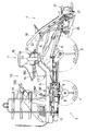
そして、図7に示すように、前記ブレーキ操作軸100は、前記主クラッチ・ブレーキペダルCBPの踏み込み操作に伴いブレーキ解除位相からブレーキ作動位相にまで回動するように主クラッチ・ブレーキペダルCBPに前後向き姿勢のロッド110を介して連動連結されている。なお、主クラッチ・ブレーキペダルCBPの操作域の途中までの第1段踏み込み操作動により前記主クラッチ50が可逆的に切り作動し、かつ、主クラッチ・ブレーキペダルCBPの引き続く操作域の終端までの第2段踏み込み操作動により走行ブレーキ99が可逆的に制動作動するように、主クラッチ・ブレーキペダルCBPを主クラッチ50及び走行ブレーキ99に連動連結してある。つまり、主クラッチ・ブレーキペダルCBPは、操作域の途中まで第1段踏み込み操作されることにより主クラッチ50を可逆的に切り作動させるとともに、操作域の終端まで第2段踏み込み操作されることにより走行ブレーキ99を制動作動させるペダルである。
【0048】
他方、前記操向クラッチ96の操作機構として、前記駆動前輪1の直進状態から設定角以上の操向作動に伴い旋回内側の操向クラッチ96を可逆的に切り作動させる操向クラッチ操作機構Zを設けてある。
【0049】
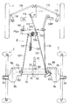
前記操向クラッチ操作機構Zは、図7、図10に示すように、前記トルクジェネレータ43で左右に揺動駆動されて駆動前輪1を操向作動させるように駆動前輪1それぞれのナックルアーム118に左右のドラグリンク119を介して連動連結するピットマンアーム111の操向作動(左右揺動)に伴い縦向き軸芯Y周りに揺動するようにピットマンアーム111に押し引きロッド112を介して連動連結する中継リンク113を設け、前記ピットマンアーム111の左側への操向に伴う中継リンク113の一方向への揺動に伴って前記縦向き軸芯Y周り一方向に揺動することにより左側のクラッチ操作軸104をロッド127を介してクラッチ入り位相からクラッチ切り位相にまで引っ張り回動させるとともに、ピットマンアーム111の右側への操向に伴う中継リンク113の反対方向への揺動に伴って前記縦向き軸芯Y周り反対方向に揺動することにより右側のクラッチ操作軸104をロッド127を介してクラッチ入り位相からクラッチ切り位相にまで回動させるように前記中継リンク113に連動する振り分けリンク114を設け、前記ピットマンアーム111の押し引きロッド112とのピン枢支連結孔115を、前記ピットマンアーム111が直進姿勢から設定角以上に揺動したときのみにピットマンアーム111の揺動を押し引きロッド112に伝達するが設定角未満の揺動は伝達しない長孔に形成して構成されている。
【0050】
前記振り分けリンク114は、図11〜図13にも示すように、前記中継リンク113を支持する軸125を介してその中継リンク113と一体揺動する連動レバー126に対して軸芯方向で遠近移動自在なものであって、接近位置することにより連動レバー126に係合連動して連動状態となり、離隔位置することにより連動レバー126から離脱して解除状態となるものである。つまり、操向クラッチ操作機構Zは、振り分けリンク113が連動状態となることにより駆動前輪1の設定角以上の操向作動に伴って旋回内側の操向クラッチ96を切り操作する作用状態に切り換わり、振り分けリンク113が解除状態となることにより駆動前輪1が設定角以上に操向作動しても操向クラッチ96を切り操作しない非作用状態に切り換わるものである。
【0051】
田植機の操作装置のうち、前記操向クラッチ操作機構Zを作用状態と非作用状態とに切り換え操作する切り換え操作手段、つまり、振り分けリンク114を接近連動位置a1と離隔解除位置a2とに変更操作するための操作手段は、図7、図10、図12、図13に示すように、横向き第1軸芯x1周りでの上下揺動により連動位置A1と解除位置A2とに変更する状態切り換え操作レバー117を前記座席15の下方に配置し、前記振り分けリンク114を接近連動位置a1に移動付勢するバネ120を設け、横向き第2軸芯x2周りでの一方向への揺動により振り分けリンク114を付勢力に抗して接近連動位置a1から離隔解除位置a2に可逆的に押圧移動させるカム121を設け、状態切り換え操作レバー117を解除位置A2に操作したときにカム121が振り分けリンク114を離隔解除位置a2に位置させる解除姿勢に揺動位置するとともに、状態切り換え操作レバー117を連動位置A1に操作したときカム121が振り分けリンク114を接近連動位置a1に位置させる連動姿勢に揺動位置するように状態切り換え操作レバー117とカム121とを連動連結させる押し引きロッド122を設けて構成されている。
【0052】
前記カム121は、振り分けリンク114に対する押圧点を含む押圧方向に沿った直線上に横向き第2軸芯x2を配置することで、振り分けリンク114を押圧する状態で解除姿勢に自己保持できるように構成されている。
【0053】
従って、この田植機では、搭乗運転部13の足元部に設置されるペダルが主クラッチ・ブレーキペダルCBPとデフロックペダルDPとの二つになって、足元部がすっきりしたものとなり、ペダル操作性及び歩行作業性などを向上できるのである。
【0054】
[第2実施形態]
上記第1実施形態において、操向クラッチ操作機構Zの切り換え操作手段として、状態切り換え操作レバー117の操作で操向クラッチ操作機構Zを切り換える手段を設けるのではなく、図14に示すように、解除ペダルAPの踏み込み操作で操向クラッチ操作機構Zを可逆的に非作用状態に切り換える手段を設け、搭乗運転部13の足元部に、前記解除ペダルAPと主クラッチ・ブレーキペダルCBPとを左右に振り分けた状態で配置する。左右一方の片足で解除ペダルAPを踏み込み操作すると同時に、左右他方の片足で主クラッチ・ブレーキペダルCBPを踏み込み操作することができるように構成されている。
【0055】
[第3実施形態]
上記第1実施形態において、操向クラッチ操作機構Zの切り換え操作手段として、状態切り換え操作レバー117の操作で操向クラッチ操作機構Zを切り換える手段を設けるのではなく、図15に示すように、解除ペダルAPの踏み込み操作で操向クラッチ操作機構Zを可逆的に非作用状態に切り換える手段を設け、搭乗運転部13の足元部に、前記解除ペダルAPとデフロックペダルDPとを、各別に踏み込み操作可能でかつ片足Fで同時踏み込み操作可能なように近づけて配置する。
【0056】
[第4実施形態]
上記第1実施形態において、操向クラッチ操作機構Zの切り換え操作手段として、状態切り換え操作レバー117の操作で操向クラッチ操作機構Zを切り換える手段を設けるのではなく、図16に示すように、解除ペダルAPの踏み込み操作で操向クラッチ操作機構Zを可逆的に非作用状態に切り換える手段を設け、搭乗運転部13の足元部に、前記解除ペダルAPと主クラッチ・ブレーキペダルCBPとを、各別に踏み込み操作可能でかつ片足Fで同時踏み込み操作可能なように近づけて配置する。
【0057】
[第5実施形態]
上記第1〜4実施形態のそれぞれにおいて、主クラッチ・ブレーキペダルCBPの操作域の途中までの第1段踏み込み操作動により主クラッチ50を可逆的に切り作動させ、かつ、主クラッチ・ブレーキペダルCBPの引き続く操作域の終端までの第2段踏み込み操作動により走行ブレーキ99を可逆的に制動作動させるようにするのではなく、主クラッチ・ブレーキペダルCBPの操作域の途中までの第1段踏み込み操作動により走行ブレーキ99を可逆的に制動作動させ、かつ、主クラッチ・ブレーキペダルCBPの引き続く操作域の終端までの第2段踏み込み操作動により主クラッチ50を可逆的に切り作動させるように構成する。この場合、主クラッチ・ブレーキペダルCBPを第1段踏み込み操作することにより、走行ブレーキ99を制動作動させて自走機体3を停止保持した状態で苗植付装置4を作動させることができる。
【0058】
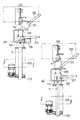
[第6実施形態]
上記第1〜5実施形態のそれぞれにおいて、振り分け伝動軸92の右側に偏った部分に対して制動作用するように走行ブレーキ99を設けるのではなく、図17に示すように、プロペラシャフト77に対して制動作用するように走行ブレーキ99を設ける。この走行ブレーキ99は内拡式のドラムブレーキであり、主クラッチ・ブレーキペダルCBPと走行ブレーキ99とを連動連結する連動連結手段は、ベルクランク200を設け、このベルクランク200を主クラッチ・ブレーキペダルCBPに連動させる長さ調整自在なターンバックル利用のロッド201と、ベルクランク200を走行ブレーキ99の作動アーム99aに連動させるロッド202とを設けて構成されている。
【0059】
[第7実施形態]
上記第1〜5実施形態のそれぞれにおいて、振り分け伝動軸92の右側に偏った部分に対して制動作用するように走行ブレーキ99を設けるのではなく、振り分け伝動軸92の左側に偏った部分に対して制動作用するように走行ブレーキ99を設ける。
【0060】
[別実施の形態]
上記実施の形態では、状態切り換え操作レバー117や解除ペダルAPからの操作力で操向クラッチ操作機構Zを切り換えるようにしたが、状態切り換え操作レバー117や解除ペダルAPの操作に伴い作動する油圧式や電動式のアクチュエータで操向クラッチ操作機構Zを切り換えるようにしても良い。
【図面の簡単な説明】
【図1】 側面図
【図2】 平面図
【図3】 要部の側面図
【図4】 要部の平面図
【図5】 ミッションケース内伝動機構の断面図
【図6】 ミッションケース内伝動機構の断面図
【図7】 操作系統図
【図8】 後車軸ケース要部(右側部)の縦断背面図
【図9】 後車軸ケース要部(左側部)の縦断背面図
【図10】 要部の側面図
【図11】 操向クラッチ操作機構要部の平面図
【図12】 操向クラッチ操作機構要部の正面図
【図13】 操向クラッチ操作機構の各状態を示す要部の側面図
【図14】 第2実施形態のペダル配置を示す概略平面図
【図15】 第3実施形態のペダル配置を示す概略平面図
【図16】 第4実施形態のペダル配置を示す概略平面図
【図17】 第6実施形態の走行ブレーキ操作系統図
【符号の説明】
1 駆動前輪
2 駆動後輪
4 水田作業装置
14 ステアリングハンドル
15 座席
50 主クラッチ
52 デフ機構
96 操向クラッチ
99 走行ブレーキ
117 状態切り換え操作レバー
CBP 主クラッチ・ブレーキペダル
AP 解除ペダル
Z 操向クラッチ操作機構[0001]
BACKGROUND OF THE INVENTION
The present invention is a paddy field work machine such as a rice transplanter, and more specifically, the transmission to each of the left and right driving rear wheels in accordance with the steering operation beyond the set angle from the straight traveling state of the left and right driving front wheels for steering. The present invention relates to a steering clutch operating mechanism that reversibly cuts and operates the left and right steering clutches that are separately turned on and off.
[0002]
[Prior art]
With this type of paddy field machine, just by steering the front wheels, the steering clutch inside the turn is disengaged and the driven rear wheels inside the turn follow and rotate. You can turn with good operability.
[0003]
As such a paddy field work machine, what is seen in Japanese Utility Model Publication No. 17-17930 is conventionally known.
That is, as the steering clutch operating mechanism, there is provided a mechanism that always operates to disengage the steering clutch inside the turning when the driving front wheel is steered beyond the set angle.
[0004]
[Problems to be solved by the invention]
However, according to the above-mentioned conventional technology, the steering clutch on the inner side of the turning is always turned off and the driving rear wheel on the inner side of the turning is not driven at the time of the small turning with the driving front wheel steering beyond the set angle. In this state, the left and right driving front wheels and the rear driving wheel on the outside of the turn will be three-wheel drive. There was a risk of getting stuck.
[0005]
An object of the present invention is to improve the traveling performance when the traveling resistance increases during a small turn when the front wheels are steered beyond a set angle.
[0006]
[Means for Solving the Problems]
The features / actions / effects of the present invention according to
[0007]
[Features] (Claim 1)
The left and right driving front wheels move straight from the straight drive state to the left and right driving rear wheels as the steering operation exceeds the set angle.Friction typeA steering clutch operating mechanism that reversibly cuts and operates one of the steering clutches inside the turning is provided.Switching operation means for switching the steering clutch operating mechanism between an operating state in which the steering clutch is operated and a non-operating state in which the steering clutch is not operated is provided.By depressing, the main clutch that turns on and off the transmission to the traveling unit and the paddy field work device is reversibly turned off and the traveling brake is reversibly braked.OneMain clutch / brake pedalIs provided on the side of the steering handle for steering the front wheels. Switch operation means below the seat behind the steering wheelIt is in the point provided.
[Features] (Claim 2)
In the present invention according to
[0008]
[Action]
Since the steering clutch operating mechanism is configured to be freely switchable between an operating state in which the steering clutch inside the turn is operated to be turned off and a non-operating state in which the steering wheel is not turned off in accordance with the steering operation over the set angle of the driving front wheel, By switching the steering clutch operating mechanism to the active state, the steering clutch can be operated while the steering clutch on the inner side of the turn can be cut and operated by simply turning the front drive wheel. By switching the mechanism to the non-operating state, it is possible to guarantee the transmission of the driving force to the left and right driving rear wheels without disengaging the steering clutch inside the turn even when the front wheels are steered beyond the set angle. .
As a result, when the running resistance increases due to an increase in the tiller depth during a small turn, the differential mechanism is switched to the non-differential state and the steering clutch operating mechanism is deactivated. By switching, sufficient thrust can be obtained by driving all of the left and right driving front wheels and the left and right driving rear wheels.
OneBy depressing the main clutch / brake pedal, the travel brake is braked and the main clutch is disengaged, so that the travel brake can be performed without overloading the engine.
[0009]
[effect]
Therefore, the steering wheel can be steered beyond the set angle while the steering wheel on the inside of the turn can be turned and operated in a small turn with good operability simply by steering the driving wheel beyond the set angle. When the running resistance is increased during the small turn, the running performance can be improved.
[0010]
The features of the present invention according to
[0011]
[Characteristic]
In the present invention according to
[0012]
[0013]
[0014]
The features of the present invention according to
[0015]
[Characteristic]
In the present invention according to
[0016]
[0017]
[0018]
[0019]
[0020]
[0021]
[0022]
[0023]
[0024]
[0025]
[0026]
DETAILED DESCRIPTION OF THE INVENTION
[First Embodiment]
As shown in FIGS. 1 and 2, a rice transplanter, which is an example of a paddy field work machine, is a riding type self-propelled
[0027]
As shown in FIGS. 3 and 4, the self-propelled
[0028]
The
[0029]
The
[0030]
The
[0031]
As shown in FIGS. 3 and 4, the
[0032]
The winding
[0033]
An
[0034]
Further, as shown in FIG. 4, a
[0035]
The hydraulic system will be described in detail. The
[0036]
In the
[0037]
The main clutch 50 is a wet multi-plate clutch, and a
The operation means for turning on and off the main clutch 50 is provided with a main clutch / brake pedal CBP that can be stepped on at the right side of the foot portion of the
[0038]
The
A small-diameter output gear 71, which meshes with the large-
[0039]
The
In the
[0040]
The one-way clutch 53 is provided so as to transmit only forward rotation of the rotation of the
[0041]
The planting
[0042]
The
[0043]
As shown in FIGS. 7 to 9, the
[0044]
A transmission system for the driving
[0045]
Of the transmission system to the driving
[0046]
100 is a brake operation shaft that reversibly press-moves the
[0047]
As shown in FIG. 7, the
[0048]
On the other hand, as the operation mechanism of the steering
[0049]
As shown in FIGS. 7 and 10, the steering clutch operating mechanism Z is moved to the
[0050]
As shown in FIGS. 11 to 13, the
[0051]
Of the operation device of the rice transplanter, switching operation means for switching the steering clutch operating mechanism Z between the operating state and the non-operating state, that is, the
[0052]
The
[0053]
Therefore, in this rice transplanter, the pedals installed at the foot portion of the
[0054]
[Second Embodiment]
In the first embodiment, as a switching operation means for the steering clutch operation mechanism Z, a means for switching the steering clutch operation mechanism Z by operating the state
[0055]
[Third Embodiment]
In the first embodiment, as a switching operation means for the steering clutch operation mechanism Z, a means for switching the steering clutch operation mechanism Z by operating the state
[0056]
[Fourth Embodiment]
In the first embodiment, as a switching operation means for the steering clutch operation mechanism Z, a means for switching the steering clutch operation mechanism Z by operating the state
[0057]
[Fifth Embodiment]
In each of the first to fourth embodiments, the main clutch 50 is reversibly disengaged by the first-step depression operation until the middle of the operation range of the main clutch / brake pedal CBP, and the main clutch / brake pedal CBP is operated. The
[0058]
[Sixth Embodiment]
In each of the first to fifth embodiments, the traveling
[0059]
[Seventh Embodiment]
In each of the first to fifth embodiments, the
[0060]
[Another embodiment]
In the above embodiment, the steering clutch operating mechanism Z is switched by the operating force from the state
[Brief description of the drawings]
[Figure 1] Side view
[Fig. 2] Plan view
[Figure 3] Side view of the main part
[Fig. 4] Plan view of the main part
[Fig. 5] Cross-sectional view of the transmission mechanism in the mission case
[Fig. 6] Cross-sectional view of the transmission mechanism in the mission case
[Figure 7] Operation system diagram
FIG. 8 is a longitudinal rear view of the main part (right side) of the rear axle case.
FIG. 9 is a vertical rear view of the main part (left side) of the rear axle case.
FIG. 10 is a side view of the main part.
FIG. 11 is a plan view of the main part of the steering clutch operating mechanism.
FIG. 12 is a front view of the main part of the steering clutch operating mechanism.
FIG. 13 is a side view of the main part showing each state of the steering clutch operating mechanism.
FIG. 14 is a schematic plan view showing the pedal arrangement of the second embodiment.
FIG. 15 is a schematic plan view showing the pedal arrangement of the third embodiment.
FIG. 16 is a schematic plan view showing the pedal arrangement of the fourth embodiment.
FIG. 17 is a travel brake operation system diagram of the sixth embodiment.
[Explanation of symbols]
1 Driving front wheel
2 Drive rear wheel
4 Paddy field equipment
14 Steering handle
15 seats
50 Main clutch
52 Differential mechanism
96 Steering clutch
99 Traveling brake
117 State switching operation lever
CBP Main clutch / brake pedal
AP release pedal
Z steering clutch operating mechanism
Claims (4)
前記操向クラッチを操作する作用状態と操作しない非作用状態とに操向クラッチ操作機構を切り換え操作する切り換え操作手段を設け、
踏み込み操作されることにより、走行部及び水田作業装置への伝動を入り切りする主クラッチを可逆的に切り作動させるとともに走行ブレーキを可逆的に制動作動させる一つの主クラッチ・ブレーキペダルを、前記駆動前輪を操向操作するためのステアリングハンドルの横側に設け、
前記切り換え操作手段をステアリングハンドルの後側の座席の下方に設けてある水田作業機。The left and right friction type steering clutches that turn the transmission to the left and right driving wheels separately according to the steering operation beyond the set angle from the straight drive state of the left and right driving front wheels for steering. Provide a steering clutch operating mechanism that reversibly cuts and operates
A switching operation means for switching the steering clutch operating mechanism between an operating state for operating the steering clutch and a non-operating state for not operating the steering clutch;
One main clutch / brake pedal that reversibly engages and disengages the main clutch that engages and disengages transmission to the traveling unit and the paddy field work device when the stepping operation is performed, Provided on the side of the steering handle for steering
A paddy field work machine in which the switching operation means is provided below the seat behind the steering wheel .
Priority Applications (1)
| Application Number | Priority Date | Filing Date | Title |
|---|---|---|---|
| JP16411599A JP4086416B2 (en) | 1999-06-10 | 1999-06-10 | Paddy field machine |
Applications Claiming Priority (1)
| Application Number | Priority Date | Filing Date | Title |
|---|---|---|---|
| JP16411599A JP4086416B2 (en) | 1999-06-10 | 1999-06-10 | Paddy field machine |
Publications (3)
| Publication Number | Publication Date |
|---|---|
| JP2000351386A JP2000351386A (en) | 2000-12-19 |
| JP2000351386A5 JP2000351386A5 (en) | 2006-08-10 |
| JP4086416B2 true JP4086416B2 (en) | 2008-05-14 |
Family
ID=15787046
Family Applications (1)
| Application Number | Title | Priority Date | Filing Date |
|---|---|---|---|
| JP16411599A Expired - Fee Related JP4086416B2 (en) | 1999-06-10 | 1999-06-10 | Paddy field machine |
Country Status (1)
| Country | Link |
|---|---|
| JP (1) | JP4086416B2 (en) |
Families Citing this family (6)
| Publication number | Priority date | Publication date | Assignee | Title |
|---|---|---|---|---|
| JP4141306B2 (en) * | 2003-03-28 | 2008-08-27 | 株式会社クボタ | Riding work machine |
| JP4511289B2 (en) * | 2004-09-03 | 2010-07-28 | 三菱農機株式会社 | Working vehicle |
| JP4926899B2 (en) * | 2007-09-20 | 2012-05-09 | 株式会社オーレック | Ride-type field cultivator |
| KR101121872B1 (en) | 2009-03-25 | 2012-03-19 | 국제종합기계 주식회사 | Rice-transplanter |
| CN102826118A (en) * | 2012-08-21 | 2012-12-19 | 厦工(三明)重型机器有限公司 | Front wheel steering hydraulic system for land scraper with composite operation and land scraper |
| KR101706706B1 (en) * | 2014-09-18 | 2017-02-15 | 주식회사 아세아텍 | Power transmission device of harrow for agricultural machine |
-
1999
- 1999-06-10 JP JP16411599A patent/JP4086416B2/en not_active Expired - Fee Related
Also Published As
| Publication number | Publication date |
|---|---|
| JP2000351386A (en) | 2000-12-19 |
Similar Documents
| Publication | Publication Date | Title |
|---|---|---|
| KR100349259B1 (en) | A riding-type paddy field working apparatus | |
| JP4629881B2 (en) | Ride type paddy field work machine | |
| JP4086416B2 (en) | Paddy field machine | |
| JP4083001B2 (en) | Paddy field machine | |
| JP4107536B2 (en) | Paddy field machine operation device | |
| JP4107537B2 (en) | Paddy field machine operation device | |
| JP2000351386A5 (en) | ||
| JP3960879B2 (en) | Paddy field machine | |
| JP2000350506A5 (en) | ||
| JP4297589B2 (en) | Ride type rice transplanter | |
| JP3687730B2 (en) | Rice transplanter | |
| JP2000350507A5 (en) | ||
| JP4454141B2 (en) | Work vehicle | |
| JP4297572B2 (en) | Ride type rice transplanter | |
| JP2000272359A (en) | Transmission device for paddy field working vehicle | |
| JP2001278102A (en) | Riding-type paddy field working machine | |
| JP2004067019A5 (en) | ||
| JP4115072B2 (en) | Ride type paddy field work machine | |
| JP4297571B2 (en) | Ride type rice transplanter | |
| JP4434463B2 (en) | Ride type paddy field work machine | |
| JP2001088731A (en) | Rice paddy field working machine of riding type | |
| JP2001278101A (en) | Riding-type paddy field working machine | |
| JP2001278096A (en) | Riding paddy field working machine | |
| JP4662296B2 (en) | Agricultural machine | |
| JP2005104299A (en) | Agricultural working machine |
Legal Events
| Date | Code | Title | Description |
|---|---|---|---|
| A621 | Written request for application examination |
Free format text: JAPANESE INTERMEDIATE CODE: A621 Effective date: 20060606 |
|
| A521 | Written amendment |
Free format text: JAPANESE INTERMEDIATE CODE: A523 Effective date: 20060628 |
|
| A977 | Report on retrieval |
Free format text: JAPANESE INTERMEDIATE CODE: A971007 Effective date: 20070711 |
|
| A131 | Notification of reasons for refusal |
Free format text: JAPANESE INTERMEDIATE CODE: A131 Effective date: 20070927 |
|
| A521 | Written amendment |
Free format text: JAPANESE INTERMEDIATE CODE: A523 Effective date: 20071115 |
|
| TRDD | Decision of grant or rejection written | ||
| A01 | Written decision to grant a patent or to grant a registration (utility model) |
Free format text: JAPANESE INTERMEDIATE CODE: A01 Effective date: 20080207 |
|
| A61 | First payment of annual fees (during grant procedure) |
Free format text: JAPANESE INTERMEDIATE CODE: A61 Effective date: 20080219 |
|
| FPAY | Renewal fee payment (event date is renewal date of database) |
Free format text: PAYMENT UNTIL: 20110228 Year of fee payment: 3 |
|
| R150 | Certificate of patent or registration of utility model |
Ref document number: 4086416 Country of ref document: JP Free format text: JAPANESE INTERMEDIATE CODE: R150 Free format text: JAPANESE INTERMEDIATE CODE: R150 |
|
| FPAY | Renewal fee payment (event date is renewal date of database) |
Free format text: PAYMENT UNTIL: 20120229 Year of fee payment: 4 |
|
| FPAY | Renewal fee payment (event date is renewal date of database) |
Free format text: PAYMENT UNTIL: 20130228 Year of fee payment: 5 |
|
| FPAY | Renewal fee payment (event date is renewal date of database) |
Free format text: PAYMENT UNTIL: 20140228 Year of fee payment: 6 |
|
| LAPS | Cancellation because of no payment of annual fees |