JP4086397B2 - Wheel dynamic load characteristic measurement device - Google Patents
Wheel dynamic load characteristic measurement device Download PDFInfo
- Publication number
- JP4086397B2 JP4086397B2 JP01454199A JP1454199A JP4086397B2 JP 4086397 B2 JP4086397 B2 JP 4086397B2 JP 01454199 A JP01454199 A JP 01454199A JP 1454199 A JP1454199 A JP 1454199A JP 4086397 B2 JP4086397 B2 JP 4086397B2
- Authority
- JP
- Japan
- Prior art keywords
- washer
- type strain
- vehicle
- strain sensor
- sensor
- Prior art date
- Legal status (The legal status is an assumption and is not a legal conclusion. Google has not performed a legal analysis and makes no representation as to the accuracy of the status listed.)
- Expired - Fee Related
Links
Images


Classifications
-
- G—PHYSICS
- G01—MEASURING; TESTING
- G01M—TESTING STATIC OR DYNAMIC BALANCE OF MACHINES OR STRUCTURES; TESTING OF STRUCTURES OR APPARATUS, NOT OTHERWISE PROVIDED FOR
- G01M17/00—Testing of vehicles
- G01M17/007—Wheeled or endless-tracked vehicles
- G01M17/06—Steering behaviour; Rolling behaviour
-
- B—PERFORMING OPERATIONS; TRANSPORTING
- B60—VEHICLES IN GENERAL
- B60G—VEHICLE SUSPENSION ARRANGEMENTS
- B60G17/00—Resilient suspensions having means for adjusting the spring or vibration-damper characteristics, for regulating the distance between a supporting surface and a sprung part of vehicle or for locking suspension during use to meet varying vehicular or surface conditions, e.g. due to speed or load
- B60G17/015—Resilient suspensions having means for adjusting the spring or vibration-damper characteristics, for regulating the distance between a supporting surface and a sprung part of vehicle or for locking suspension during use to meet varying vehicular or surface conditions, e.g. due to speed or load the regulating means comprising electric or electronic elements
- B60G17/019—Resilient suspensions having means for adjusting the spring or vibration-damper characteristics, for regulating the distance between a supporting surface and a sprung part of vehicle or for locking suspension during use to meet varying vehicular or surface conditions, e.g. due to speed or load the regulating means comprising electric or electronic elements characterised by the type of sensor or the arrangement thereof
-
- B—PERFORMING OPERATIONS; TRANSPORTING
- B60—VEHICLES IN GENERAL
- B60G—VEHICLE SUSPENSION ARRANGEMENTS
- B60G17/00—Resilient suspensions having means for adjusting the spring or vibration-damper characteristics, for regulating the distance between a supporting surface and a sprung part of vehicle or for locking suspension during use to meet varying vehicular or surface conditions, e.g. due to speed or load
- B60G17/015—Resilient suspensions having means for adjusting the spring or vibration-damper characteristics, for regulating the distance between a supporting surface and a sprung part of vehicle or for locking suspension during use to meet varying vehicular or surface conditions, e.g. due to speed or load the regulating means comprising electric or electronic elements
- B60G17/0195—Resilient suspensions having means for adjusting the spring or vibration-damper characteristics, for regulating the distance between a supporting surface and a sprung part of vehicle or for locking suspension during use to meet varying vehicular or surface conditions, e.g. due to speed or load the regulating means comprising electric or electronic elements characterised by the regulation being combined with other vehicle control systems
-
- B—PERFORMING OPERATIONS; TRANSPORTING
- B60—VEHICLES IN GENERAL
- B60G—VEHICLE SUSPENSION ARRANGEMENTS
- B60G7/00—Pivoted suspension arms; Accessories thereof
- B60G7/04—Buffer means for limiting movement of arms
-
- B—PERFORMING OPERATIONS; TRANSPORTING
- B60—VEHICLES IN GENERAL
- B60G—VEHICLE SUSPENSION ARRANGEMENTS
- B60G2200/00—Indexing codes relating to suspension types
- B60G2200/10—Independent suspensions
- B60G2200/14—Independent suspensions with lateral arms
- B60G2200/144—Independent suspensions with lateral arms with two lateral arms forming a parallelogram
-
- B—PERFORMING OPERATIONS; TRANSPORTING
- B60—VEHICLES IN GENERAL
- B60G—VEHICLE SUSPENSION ARRANGEMENTS
- B60G2202/00—Indexing codes relating to the type of spring, damper or actuator
- B60G2202/30—Spring/Damper and/or actuator Units
- B60G2202/31—Spring/Damper and/or actuator Units with the spring arranged around the damper, e.g. MacPherson strut
- B60G2202/312—The spring being a wound spring
-
- B—PERFORMING OPERATIONS; TRANSPORTING
- B60—VEHICLES IN GENERAL
- B60G—VEHICLE SUSPENSION ARRANGEMENTS
- B60G2204/00—Indexing codes related to suspensions per se or to auxiliary parts
- B60G2204/10—Mounting of suspension elements
- B60G2204/11—Mounting of sensors thereon
- B60G2204/112—Mounting of sensors thereon on dampers, e.g. fluid dampers
-
- B—PERFORMING OPERATIONS; TRANSPORTING
- B60—VEHICLES IN GENERAL
- B60G—VEHICLE SUSPENSION ARRANGEMENTS
- B60G2204/00—Indexing codes related to suspensions per se or to auxiliary parts
- B60G2204/40—Auxiliary suspension parts; Adjustment of suspensions
- B60G2204/45—Stops limiting travel
- B60G2204/4502—Stops limiting travel using resilient buffer
-
- B—PERFORMING OPERATIONS; TRANSPORTING
- B60—VEHICLES IN GENERAL
- B60G—VEHICLE SUSPENSION ARRANGEMENTS
- B60G2400/00—Indexing codes relating to detected, measured or calculated conditions or factors
- B60G2400/05—Attitude
- B60G2400/051—Angle
- B60G2400/0513—Yaw angle
-
- B—PERFORMING OPERATIONS; TRANSPORTING
- B60—VEHICLES IN GENERAL
- B60G—VEHICLE SUSPENSION ARRANGEMENTS
- B60G2400/00—Indexing codes relating to detected, measured or calculated conditions or factors
- B60G2400/10—Acceleration; Deceleration
- B60G2400/104—Acceleration; Deceleration lateral or transversal with regard to vehicle
-
- B—PERFORMING OPERATIONS; TRANSPORTING
- B60—VEHICLES IN GENERAL
- B60G—VEHICLE SUSPENSION ARRANGEMENTS
- B60G2400/00—Indexing codes relating to detected, measured or calculated conditions or factors
- B60G2400/10—Acceleration; Deceleration
- B60G2400/106—Acceleration; Deceleration longitudinal with regard to vehicle, e.g. braking
-
- B—PERFORMING OPERATIONS; TRANSPORTING
- B60—VEHICLES IN GENERAL
- B60G—VEHICLE SUSPENSION ARRANGEMENTS
- B60G2400/00—Indexing codes relating to detected, measured or calculated conditions or factors
- B60G2400/20—Speed
- B60G2400/204—Vehicle speed
-
- B—PERFORMING OPERATIONS; TRANSPORTING
- B60—VEHICLES IN GENERAL
- B60G—VEHICLE SUSPENSION ARRANGEMENTS
- B60G2400/00—Indexing codes relating to detected, measured or calculated conditions or factors
- B60G2400/25—Stroke; Height; Displacement
- B60G2400/252—Stroke; Height; Displacement vertical
-
- B—PERFORMING OPERATIONS; TRANSPORTING
- B60—VEHICLES IN GENERAL
- B60G—VEHICLE SUSPENSION ARRANGEMENTS
- B60G2400/00—Indexing codes relating to detected, measured or calculated conditions or factors
- B60G2400/40—Steering conditions
- B60G2400/41—Steering angle
-
- B—PERFORMING OPERATIONS; TRANSPORTING
- B60—VEHICLES IN GENERAL
- B60G—VEHICLE SUSPENSION ARRANGEMENTS
- B60G2400/00—Indexing codes relating to detected, measured or calculated conditions or factors
- B60G2400/60—Load
- B60G2400/61—Load distribution
-
- B—PERFORMING OPERATIONS; TRANSPORTING
- B60—VEHICLES IN GENERAL
- B60G—VEHICLE SUSPENSION ARRANGEMENTS
- B60G2400/00—Indexing codes relating to detected, measured or calculated conditions or factors
- B60G2400/80—Exterior conditions
- B60G2400/82—Ground surface
- B60G2400/822—Road friction coefficient determination affecting wheel traction
-
- B—PERFORMING OPERATIONS; TRANSPORTING
- B60—VEHICLES IN GENERAL
- B60G—VEHICLE SUSPENSION ARRANGEMENTS
- B60G2401/00—Indexing codes relating to the type of sensors based on the principle of their operation
- B60G2401/12—Strain gauge
-
- B—PERFORMING OPERATIONS; TRANSPORTING
- B60—VEHICLES IN GENERAL
- B60G—VEHICLE SUSPENSION ARRANGEMENTS
- B60G2800/00—Indexing codes relating to the type of movement or to the condition of the vehicle and to the end result to be achieved by the control action
- B60G2800/21—Traction, slip, skid or slide control
- B60G2800/212—Transversal; Side-slip during cornering
-
- B—PERFORMING OPERATIONS; TRANSPORTING
- B60—VEHICLES IN GENERAL
- B60G—VEHICLE SUSPENSION ARRANGEMENTS
- B60G2800/00—Indexing codes relating to the type of movement or to the condition of the vehicle and to the end result to be achieved by the control action
- B60G2800/21—Traction, slip, skid or slide control
- B60G2800/214—Traction, slip, skid or slide control by varying the load distribution
-
- B—PERFORMING OPERATIONS; TRANSPORTING
- B60—VEHICLES IN GENERAL
- B60G—VEHICLE SUSPENSION ARRANGEMENTS
- B60G2800/00—Indexing codes relating to the type of movement or to the condition of the vehicle and to the end result to be achieved by the control action
- B60G2800/22—Braking, stopping
-
- B—PERFORMING OPERATIONS; TRANSPORTING
- B60—VEHICLES IN GENERAL
- B60G—VEHICLE SUSPENSION ARRANGEMENTS
- B60G2800/00—Indexing codes relating to the type of movement or to the condition of the vehicle and to the end result to be achieved by the control action
- B60G2800/24—Steering, cornering
-
- B—PERFORMING OPERATIONS; TRANSPORTING
- B60—VEHICLES IN GENERAL
- B60G—VEHICLE SUSPENSION ARRANGEMENTS
- B60G2800/00—Indexing codes relating to the type of movement or to the condition of the vehicle and to the end result to be achieved by the control action
- B60G2800/70—Estimating or calculating vehicle parameters or state variables
-
- B—PERFORMING OPERATIONS; TRANSPORTING
- B60—VEHICLES IN GENERAL
- B60G—VEHICLE SUSPENSION ARRANGEMENTS
- B60G2800/00—Indexing codes relating to the type of movement or to the condition of the vehicle and to the end result to be achieved by the control action
- B60G2800/90—System Controller type
- B60G2800/91—Suspension Control
-
- B—PERFORMING OPERATIONS; TRANSPORTING
- B60—VEHICLES IN GENERAL
- B60G—VEHICLE SUSPENSION ARRANGEMENTS
- B60G2800/00—Indexing codes relating to the type of movement or to the condition of the vehicle and to the end result to be achieved by the control action
- B60G2800/90—System Controller type
- B60G2800/93—Skid or slide control [ASR]
Landscapes
- Engineering & Computer Science (AREA)
- Mechanical Engineering (AREA)
- Automation & Control Theory (AREA)
- Physics & Mathematics (AREA)
- General Physics & Mathematics (AREA)
- Vehicle Body Suspensions (AREA)
- Force Measurement Appropriate To Specific Purposes (AREA)
Description
【0001】
【発明の属する技術分野】
本発明は自動車の車輪(タイヤ)の動荷重特性計測装置、特に、走行中の自動車の車輪にかかる荷重(動荷重)を計測する動荷重特性計測装置に関する。
【0002】
【従来の技術】
従来、走行中の自動車の4輪にかかる荷重、即ち動荷重の計測が困難であった為、タイヤにどの程度の負荷がかかっているのかを簡便に且つ十分に把握することができず、一般には、走行後のタイヤの磨耗の程度やタイヤトレッドの表面温度等を測定することにより、これらの測定値からタイヤの動荷重を推測するしか方法がなかった。
【0003】
また、車両の運動特性に大きな影響を与えているとされている、左右車輪の動荷重移動量によるロール変化率、動荷重ごとのタイヤ実車コーナリング特性、或いはタイヤと路面との限界摩擦係数等を、定量的に把握することは困難であった。
近年のますます高度化した自動車の旋回特性、制動特性、WET性能を要求されるレース用タイヤの開発にあたっては、上記のような実車の動的荷重特性を定量的に把握することが重要であり、必然的に4輪の動荷重計測が不可欠となってきている。
【0004】
特開平6−227225号公報では、車両の懸架装置又は支持装置に、力を加えると電荷を発生する水晶圧電素子を組み込み、この水晶圧電素子で計測した負荷の大きさと方向により、路面又は軌条等の凹凸を検知すると共に、その検知した情報に基づいてサーボ機構で油圧又は空圧機構を制御して、路面又は軌条等の凹凸による車体の揺れを抑制することが開示されている。
【0005】
【発明が解決しようとする課題】
しかしながら、特開平6−227225号公報に開示されているような水晶圧電素子を用いることは高価であり、車両の適当な部位への取付けが困難であり、また水晶圧電素子の設置場所によっては、走行中の車輪の動荷重特性を十分正確に把握することが困難となっていた。
【0006】
上記のような事情に鑑み、本発明では、車両本体と車輪との間で路面からの力を受ける部位への設置が比較的容易であり、且つ安価で十分正確に走行中の車輪の動荷重特性を把握することが可能な、車輪の動荷重特性計測装置を提供することを目的とする。
【0007】
【課題を解決するための手段】
上記の課題を達成するために、本発明によれば、車両本体と車輪との間で、路面からの力を受ける部位に組み込まれた、車輪の動荷重を検出するワッシャー型歪みセンサと、車速を検出するセンサと、操舵角を検出するセンサと、横方向の重力加速度(G)及び縦方向の重力加速度(G)を検出するセンサと、車輪のヨー角を検出するセンサと、ダンパーストロークを検出するセンサと、これらのセンサからの信号を入力し、これらのデータにより、車両が限界横Gで走行していると仮定した場合の、接地面におけるタイヤの進行方向と直交の方向に発生している力としてのタイヤコーナリングフォース、車両が旋回中に発生するタイヤと路面と摩擦係数、及び車体重心の真横を中心として定常円旋回した場合のタイヤスリンプ角を求め、タイヤ実車コーナリング特性を出力するデータロガーと、を具備することを特徴とする車輪の動荷重特性計測装置が提供される。ワッシャー型歪みセンサは、車輪が路面から受ける動荷重に応じて歪み、その歪みに対応した電圧を発生する。
【0008】
本発明において、ワッシャー型歪みセンサは、車両の懸架装置のショックアブソーバの本体側取付部に組み込まれていることを特徴とする。この場合において、ワッシャー型歪みセンサは、車両の懸架装置のショックアブソーバの本体側と、下端が車輪側ロアーシートに接するスプリングとの間に取り付けられている。また、ワッシャー型歪みセンサは、前記ショックアブソーバの本体側との間に第1アタッチメントを挟み、かつスプリングとの間に第2アタッチメントを挟むように保持されている。これにより、ワッシャー型歪みセンサには、路面から受ける動荷重、即ちスプリングが受ける荷重を直接受けることができる。
【0009】
第1アタッチメントのワッシャー型歪みセンサと接する面には、該ワッシャー型歪みセンサと接する外周部分の除き、窪み部が形成されている。これと対応して、ワッシャー型歪みセンサの第1アタッチメントの接する面には、該ワッシャー型歪みセンサと接する外周部分の除き、窪み部が形成されている。これにより、車輪の等荷重によりワッシャー型歪みセンサが歪みを生じても、このワッシャー型歪みセンサの歪みにより変形しても、それ自体が第1アタッチメントと干渉することが避けられる。
【0010】
ワッシャー型歪みセンサの第2アタッチメントと接する面は、外周部分の除き突起した面を有し、該突起した面が第2アタッチメントと接する。これにより、ワッシャー型歪みセンサはスプリングからの荷重をこの突出した面で直接受けることができる。
【0011】
【発明の実施の形態】
以下、添付図面を参照して本発明の実施の形態について詳細に説明する。
まず、図1及び図2において、本発明の車輪の動荷重特性計測装置を組み込む、自動車の懸架装置のショックアブソーバについて説明する。
図1は一般に使用されている自動車のショックアブソーバ10を示すもので、その上側は自動車の本体フレーム(クロスメンバ)12に固定され、下側はフレーム12に枢着されたロア・アーム14を介してアクスル(車軸)16に固定されている。
【0012】
ショックアブソーバ10はよく知られているように、スプリング18が衝撃などにより圧縮される際は圧縮を和らげるように作用し、スプリングが延びるときはスプリングの跳ね返りを抑えるように作用して、スプリングの延び縮みによるばねのはね返りを取り除き、減衰力を働かせて車体を安定に保つ作用をする。スプリング18は、図2に示すように、通常、ショックアブソーバ10の本体側アッバーシート20と車輪側ロアーシート22との間に設けられている。
【0013】
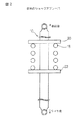
本発明では、ワッシャー型歪みセンサ24(ロードセル)が動荷重を計測する自動車の前後4輪の各車輪の路面からの力を受ける部位に組み込まれる。例えば、図3においては、ワッシャー型歪みセンサ24を、ショックアブソーバのスプリング18を受けるアッパーシート20の部分に挾み込まれている状態を示す。即ち、ワッシャー型歪みセンサ24は、ショックアブソーバの本体側に固定された第1アタッチメント26とスプリング18に接する第2アタッチメント28との間に挟まれるように保持される。このようなワッシャー型歪みセンサ24は自動車の4輪の各々に取付けられる。
【0014】
第1アタッチメント26は、ワッシャー型歪みセンサ24が路面からの応力によって歪む際に、ワッシャー型歪みセンサ24自体の変位に干渉することのないようにされる。このため、例えば、第1アタッチメント26のワッシャー型歪みセンサ24の取付側は、外周部26aのみを残し他の部分は窪んだ凹形状26bとされており、一方、ワッシャー型歪みセンサ24の第1アタッチメント26側はその外周部24aのみを残し他の部分は窪んだ凹形状24bとされている。これにより、例えばワッシャー型歪みセンサ24が路面からの応力により上下方向に撓んでとしても歪みセンサ24自体がその変位により第1アタッチメント26の凹状部26bの内側面に干渉して、計測誤差を生ずることがなくなる。
【0015】
また、スプリング18側の第2アタッチメント28は、路面からの応力をワッシャー型歪みセンサ24に伝達するべく、平面状に形成されており、一方、ワッシャー型歪みセンサ24の第2アタッチメント28側はその外周部24cのみを残し他の部分は突出した凸形状の面24dとされている。これにより、路面からタイヤに伝わる応力は第2アタッチメント28より、ワッシャー型歪みセンサ24の凸形状の面24d(荷重入力面)を介して直接伝達される。
【0016】
図4は、図3と同様、ワッシャー型歪みセンサ(ロードセル)24をショックアブソーバ10のスプリング18を受けるアッバーシート20の部分に組み込むと共に、同じショックアブソーバ10にダンパーストロークセンサ30をも組み込んだ状態を示す。
ダンパーストロークセンサ30は、ショックアブソーバ10の車体側のアッパーシート20と、スプリング18を受ける車輪側のロアシートとの間に組み込まれ、自動車の走行中のショックアブソーバ10のストロークの変化を検出する。
【0017】
図5(a)及び(b)は本実施形態で使用するワッシャー型歪みセンサ24を示す。
このワッシャー型歪みセンサ24は略リング状であって、リング状の部分がセンサ部で、軸方向の一方の面(図5(a)の下面)はその外周部24aのみを残し内側部分が軸方向に窪んだ凹形状24bとされ、他方の面(図5(a)の上面)はその外周部24cのみを残し他の部分が突出した凸形状24dとされている。リング状の部分がセンサ部であって、ケーブル24fが接続されていて、歪みによる電気的な検出信号が取り出される。
【0018】
図6は車輪の動荷重移動量によるロール変化率、動荷重毎のタイヤ実車コーナリング特性、タイヤと路面との限界摩擦係数、等を計測するためのシステム構成を示す図である。車速を検出するための車速トリガセンサ32、操舵角を検出するための操舵角センサ34、車両の横方向の重力加速度(G)及び前後方向の重力加速度(G)を検出する横G・前後Gセンサ36、車輪のヨー角速度を検出するヨー角速度センサ38、並びに図4に示したワッシャー型歪みセンサ24及びダンパーストロークセンサ30が設けられ、各センサの出力はアンプ40を介してデータロガー42に入力され、上記の実車データが得られる。
【0019】
【実施例】
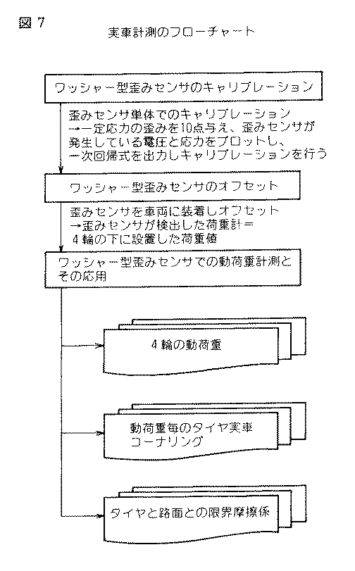
図7は実車計測の手順をフローチャートで示す。
まず、ワッシャー型歪みセンサ24として、株式会社共和電業製のLCW−CS(ワッシャー型ロードセル)(2トン用)を使用し、次の手順によりキャリブレーションを行った。ワッシャー型歪みセンサ24を単体でブレス機(図示せず)に挟み一定応力を加え、その時に発生している歪みを電圧で検出した。プレス機での応力検出は10点で行い、ワッシャー型歪みセンサ24で発生している歪み(電圧)を一次式でプロットしワッシャー型歪みセンサ24のキャリブレーションを行った。
【0020】
次に、ワッシャー型歪みセンサ24のオフセットを行った。ワッシャー型歪みセンサ24を各単体についてキャリブレーションを行った後、ワッシャー型歪みセンサ24が検出した荷重値を、車両に装着した状態で4輪の下に設置した荷重計に合わせ、ワッシャー型歪みセンサ24のオフセットを行った。
次に、上述のようなワッシャー型歪みセンサ24を車両の4輪に取付け、現場(サーキット)にて実際に計測を行い、4輪動荷重、動荷重毎のタイヤ実車コーナリング特性、タイヤと路面との限界摩擦係数を求めた。タイヤ実車コーナリング特性を図8に、タイヤと路面との限界摩擦係数を図9にそれぞれ示す。なお、実験にあたっての測定条件は次のとおりであった。
【0021】
【0022】
データロガー42は車内の空いているスペースで熱の発生のない部位に設置した。車速トリガーセンサ32は、ホイール回転を検出するトヨタTRD製のトリガーをブレーキキャリパー(図示せず)の内側に設置した。操舵角センサ34は、操舵輪(ステアリング)を回転することによって変異するステアリングストロークロッド(図示せず)に設置した。このセンサのキャリブレーションにて、ストローク変異を角度に変換する。
【0023】
横G及び前後Gセンサ36は、車両の中心線上で、できるだけ車両重心に近い位置に設置した。ダンパーストロークセンサ30は、図4に示したように、ショックアブソーバ10のアッパーシート20とロアーシート22との間に設置し、アッパーシート20とロアーシート22間の相対的変位を検出した。4輪動荷重センサ(ワッシャー型歪みセンサ)24は前述のように、ショックアブソーバ10のアッパーシートの部位で、スプリングの荷重を受ける部分に挟まれるように設置した。
【0024】
上記の「Piシステム」にて採取した実車データは、テキストファイルへダウンロードした後、所定のプログラムにて「タイヤ実車コーナリング特性」を出力した。
車両の「タイヤ実車コーナリング特性」に関する関係式は次のとおりである。
(1) タイヤコーナリングフォース(横力、CF特性)
車両が限界横Gで走行していると仮定し、タイヤの接地面におけるタイヤの進行方向と直角の方向に発生している力
(2) 車両が旋回中に発生するタイヤと路面との摩擦係数μ(横力係数)
μ=横力/動荷重(計測値)
=横G×静荷重/動荷重
(3) タイヤスリップ角(車体が重心真横を中心として定常円旋回、即ち一定半径の円周上を同一速度で回転していると仮定)
タイヤの向きと車両の進行方向との角度:
フロントスリップ角: βf=−γ×Lf/v+θ/N
リヤースリップ角: βr=γ×Lr/v
ここで、Vは車速、γはヨーレート(旋回角速度[ deg/sec ])、θは舵角(ステアリング・ハンドルを切った角度)、Lfはフロント車軸とヨーレートとの間の距離、Lrはヨーレートとリヤー車軸との距離、Nはステアリングギア比(ステアリングを切ることによって生ずる実際の車軸に加わる角度変化の比)である。
【0025】
図8及び図9において、横軸はフロントスリップ角(°)であり、縦軸は摩擦係数(μ)である。図8は鈴鹿サーキットでの結果であり、動荷重毎のタイヤ実車コーナリング特性を示す。図9における(a)は鈴鹿、(b)は富士、(c)は十勝の各鈴鹿サーキットでの結果であり、タイヤと路面との限界摩擦係数を示す。
【0026】
以上、添付図面を参照して本発明の実施形態及び実施例について詳細に説明したが、本発明は上記の実施形態や実施例に限定されるものではなく、本発明の精神ないし範囲内において種々の形態、変形、修正等が可能であることに留意すべきである。
【0027】
【発明の効果】
以上に説明したように、本発明によれば、車両の走行中の4輪動荷重を正確に計測することが可能となり、タイヤへの負荷、動荷重毎のタイヤ実車コーナリング特性、タイヤと路面との限界摩擦係数を数値にて把握することができ、より高度化した旋回特性、制動特性、WET性能等についてタイヤ仕様間での定量評価を行うことが可能になった。
【図面の簡単な説明】
【図1】一般に使用されている自動車のショックアブソーバを示す図である。
【図2】従来のショックアブソーバの概略図である。
【図3】ワッシャー型歪みセンサを組み込んだ本発明に係るショックアブソーバの概略図である。
【図4】ワッシャー型歪みセンサ及びダンパーストロークセンサを有する組み込んだ本発明に係るショックアブソーバの概略図である。
【図5】ワッシャー型歪みセンサの側面図(a)及び平面図(b)である。
【図6】車輪の動荷重特性を計測するためのシステム構成を示す図である。
【図7】実車計測のフローチャートである。
【図8】動荷重毎のタイヤ実車コーナリング特性の測定結果を示す図である。
【図9】タイヤと路面との限界摩擦係数の測定結果を示す図である。
【符号の説明】
10…ショックアブソーバ
12…車体フレーム
14…ロアアーム
16…アクスル
18…スプリング
20…アッパーシート
22…ロアーシート
24…ワッシャー型歪みセンサ
26…第1アタッチメント
28…第2アタッチメント
30…ダンパーストロークセンサ[0001]
BACKGROUND OF THE INVENTION
The present invention relates to a dynamic load characteristic measuring device for a vehicle wheel (tire), and more particularly to a dynamic load characteristic measuring device for measuring a load (dynamic load) applied to a wheel of a running vehicle.
[0002]
[Prior art]
Conventionally, since it has been difficult to measure the load applied to the four wheels of a running car, that is, the dynamic load, it is not possible to easily and sufficiently grasp how much load is applied to the tire. The only way to estimate the dynamic load of a tire from these measured values is by measuring the degree of wear of the tire after running, the surface temperature of the tire tread, and the like.
[0003]
In addition, the rate of change of roll due to the amount of movement of the dynamic load of the left and right wheels, the tire cornering characteristics for each dynamic load, or the critical friction coefficient between the tire and the road surface, which is said to have a great influence on the vehicle's motion characteristics, etc. It was difficult to grasp quantitatively.
It is important to quantitatively grasp the dynamic load characteristics of actual vehicles as described above in the development of racing tires that require increasingly sophisticated turning characteristics, braking characteristics, and WET performance of automobiles in recent years. Inevitably, measuring the dynamic load of four wheels has become indispensable.
[0004]
In Japanese Patent Laid-Open No. 6-227225, a quartz piezoelectric element that generates an electric charge when a force is applied is incorporated in a suspension or support device of a vehicle, and depending on the magnitude and direction of a load measured by the quartz piezoelectric element, a road surface or a rail or the like It is disclosed that the unevenness of the vehicle body is detected, and the hydraulic or pneumatic mechanism is controlled by the servo mechanism based on the detected information to suppress the shaking of the vehicle body due to the unevenness on the road surface or rails.
[0005]
[Problems to be solved by the invention]
However, it is expensive to use a crystal piezoelectric element as disclosed in JP-A-6-227225, and it is difficult to attach it to an appropriate part of the vehicle. It has been difficult to grasp the dynamic load characteristics of the running wheel sufficiently accurately.
[0006]
In view of the circumstances as described above, in the present invention, it is relatively easy to install on a portion that receives a force from the road surface between the vehicle main body and the wheel, and the dynamic load of the traveling wheel is sufficiently accurate at low cost. An object of the present invention is to provide a dynamic load characteristic measuring device for wheels capable of grasping characteristics.
[0007]
[Means for Solving the Problems]
To achieve the above object, according to the present invention, between the vehicle body and the wheels, integrated into the site to receive a force from the road surface, and a washer-type strain sensors for detecting the dynamic load of the wheel, vehicle speed A sensor for detecting the steering angle, a sensor for detecting the lateral gravitational acceleration (G) and the vertical gravitational acceleration (G), a sensor for detecting the yaw angle of the wheel, and a damper stroke. Sensors to be detected and signals from these sensors are input, and these data are generated in a direction perpendicular to the tire traveling direction on the contact surface when it is assumed that the vehicle is running at the limit lateral G. Tire cornering force as the driving force, tire and road surface and friction coefficient generated while the vehicle is turning, and tire slip angle when the vehicle is turning in a steady circle around the side of the center of gravity of the vehicle. The dynamic load characteristic measuring apparatus of the wheels, characterized is provided that includes a data logger that outputs Ya vehicle cornering characteristics, a. The washer-type strain sensor is distorted according to the dynamic load that the wheel receives from the road surface, and generates a voltage corresponding to the strain.
[0008]
In the present invention, the washer-type strain sensor is incorporated in a body-side mounting portion of a shock absorber of a vehicle suspension device. In this case, the washer-type strain sensor is attached between the body side of the shock absorber of the vehicle suspension system and a spring whose lower end is in contact with the wheel side lower seat. The washer-type strain sensor is held such that the first attachment is sandwiched between the shock absorber and the second attachment between the shock absorber and the spring. Thereby, the washer-type strain sensor can directly receive a dynamic load received from the road surface, that is, a load received by the spring.
[0009]
On the surface of the first attachment that contacts the washer-type strain sensor, a recess is formed except for the outer peripheral portion that contacts the washer-type strain sensor. Correspondingly, a recess is formed on the surface of the washer-type strain sensor in contact with the first attachment except for the outer peripheral portion in contact with the washer-type strain sensor. Thus, even if the washer-type strain sensor is distorted by the equal load of the wheel or is deformed by the strain of the washer-type strain sensor, it can be avoided that it itself interferes with the first attachment.
[0010]
The surface in contact with the second attachment of the washer-type strain sensor has a protruding surface except for the outer peripheral portion, and the protruding surface is in contact with the second attachment. Thus, washer-type strain sensors Ru can receive directly a plane that the projecting load from the spring.
[0011]
DETAILED DESCRIPTION OF THE INVENTION
Hereinafter, embodiments of the present invention will be described in detail with reference to the accompanying drawings.
First, in FIG. 1 and FIG. 2, a shock absorber for a suspension system of an automobile incorporating the dynamic load characteristic measuring device for wheels of the present invention will be described.
FIG. 1 shows a commonly used
[0012]
As is well known, the shock absorber 10 acts to soften the compression when the
[0013]
In the present invention, a washer-type strain sensor 24 (load cell) is incorporated in a portion that receives a force from the road surface of each of the four front and rear wheels of the automobile for measuring the dynamic load. For example, FIG. 3 shows a state in which the washer-
[0014]
The
[0015]
Further, the
[0016]
4, as in FIG. 3, the washer-type strain sensor (load cell) 24 is incorporated in the portion of the
The
[0017]
5A and 5B show a washer-
This washer-
[0018]
FIG. 6 is a diagram showing a system configuration for measuring a roll change rate according to a dynamic load movement amount of a wheel, a tire actual vehicle cornering characteristic for each dynamic load, a critical friction coefficient between a tire and a road surface, and the like. A vehicle
[0019]
【Example】
FIG. 7 is a flowchart showing the procedure of actual vehicle measurement.
First, as a washer
[0020]
Next, the washer-
Next, the washer-
[0021]
[0022]
The
[0023]
The lateral G and front / rear G sensors 36 are installed as close to the vehicle center of gravity as possible on the center line of the vehicle. As shown in FIG. 4, the
[0024]
The actual vehicle data collected by the above “Pi system” was downloaded to a text file and then “tire actual vehicle cornering characteristics” was output by a predetermined program.
The relational expression regarding the “tire tire cornering characteristics” of the vehicle is as follows.
(1) Tire cornering force (lateral force, CF characteristics)
Assuming that the vehicle is traveling at the limit lateral G, the force generated in the direction perpendicular to the tire traveling direction on the tire contact surface
(2) Coefficient of friction μ (lateral force coefficient) between the tire and the road surface generated while the vehicle is turning
μ = lateral force / dynamic load (measured value)
= Lateral G x Static load / Dynamic load
(3) Tire slip angle (assuming that the vehicle body is turning in a steady circle around the right side of the center of gravity, that is, rotating on the circumference of a certain radius at the same speed)
Angle between tire direction and vehicle direction:
Front slip angle: βf = −γ × Lf / v + θ / N
Rear slip angle: βr = γ × Lr / v
Where V is the vehicle speed, γ is the yaw rate (turning angular velocity [deg / sec]), θ is the rudder angle (the angle at which the steering wheel is turned), Lf is the distance between the front axle and the yaw rate, and Lr is the yaw rate. The distance from the rear axle, N is the steering gear ratio (the ratio of the change in angle applied to the actual axle caused by turning off the steering).
[0025]
8 and 9, the horizontal axis represents the front slip angle (°), and the vertical axis represents the friction coefficient (μ). FIG. 8 shows the results at the Suzuka Circuit, and shows the actual tire cornering characteristics for each dynamic load. In FIG. 9, (a) is the result at Suzuka, (b) is the result at Fuji, and (c) is the result at each Suzuka circuit in Tokachi, and shows the friction coefficient between the tire and the road surface.
[0026]
Although the embodiments and examples of the present invention have been described in detail with reference to the accompanying drawings, the present invention is not limited to the above-described embodiments and examples, and various modifications can be made within the spirit and scope of the present invention. It should be noted that the present invention can be modified, modified, etc.
[0027]
【The invention's effect】
As described above, according to the present invention, it is possible to accurately measure the four-wheel dynamic load while the vehicle is running, the load on the tire, the tire actual vehicle cornering characteristics for each dynamic load, the tire and the road surface. This makes it possible to quantitatively evaluate tire specifications for more advanced turning characteristics, braking characteristics, WET performance, and the like.
[Brief description of the drawings]
FIG. 1 is a view showing a shock absorber of a generally used automobile.
FIG. 2 is a schematic view of a conventional shock absorber.
FIG. 3 is a schematic view of a shock absorber according to the present invention incorporating a washer-type strain sensor.
FIG. 4 is a schematic view of a shock absorber according to the present invention having a washer-type strain sensor and a damper stroke sensor.
FIGS. 5A and 5B are a side view and a plan view of a washer-type strain sensor. FIGS.
FIG. 6 is a diagram showing a system configuration for measuring dynamic load characteristics of wheels.
FIG. 7 is a flowchart of actual vehicle measurement.
FIG. 8 is a diagram showing measurement results of tire actual vehicle cornering characteristics for each dynamic load.
FIG. 9 is a diagram showing a measurement result of a limit friction coefficient between a tire and a road surface.
[Explanation of symbols]
DESCRIPTION OF
Claims (7)
Priority Applications (4)
| Application Number | Priority Date | Filing Date | Title |
|---|---|---|---|
| JP01454199A JP4086397B2 (en) | 1999-01-22 | 1999-01-22 | Wheel dynamic load characteristic measurement device |
| GB0001454A GB2346218B (en) | 1999-01-22 | 2000-01-21 | Apparatus for measuring dynamic load characteristics of wheels |
| US09/488,558 US6516657B2 (en) | 1999-01-22 | 2000-01-21 | Apparatus for measuring dynamic load characteristics of wheels |
| US09/908,818 US6658924B2 (en) | 1999-01-22 | 2001-07-20 | Method for measuring dynamic characteristics of wheel of vehicle |
Applications Claiming Priority (1)
| Application Number | Priority Date | Filing Date | Title |
|---|---|---|---|
| JP01454199A JP4086397B2 (en) | 1999-01-22 | 1999-01-22 | Wheel dynamic load characteristic measurement device |
Publications (2)
| Publication Number | Publication Date |
|---|---|
| JP2000214012A JP2000214012A (en) | 2000-08-04 |
| JP4086397B2 true JP4086397B2 (en) | 2008-05-14 |
Family
ID=11864023
Family Applications (1)
| Application Number | Title | Priority Date | Filing Date |
|---|---|---|---|
| JP01454199A Expired - Fee Related JP4086397B2 (en) | 1999-01-22 | 1999-01-22 | Wheel dynamic load characteristic measurement device |
Country Status (3)
| Country | Link |
|---|---|
| US (1) | US6516657B2 (en) |
| JP (1) | JP4086397B2 (en) |
| GB (1) | GB2346218B (en) |
Families Citing this family (35)
| Publication number | Priority date | Publication date | Assignee | Title |
|---|---|---|---|---|
| US6532811B2 (en) * | 2001-01-26 | 2003-03-18 | Bridgestone/Firestone North American Tire, Llc | Method of wear testing a tire |
| US20030058118A1 (en) * | 2001-05-15 | 2003-03-27 | Wilson Kitchener C. | Vehicle and vehicle tire monitoring system, apparatus and method |
| US20040159515A1 (en) * | 2003-02-19 | 2004-08-19 | Bell Stephen H. | Coil over shock absorber with spring seat load adjusted damping |
| DE102004001250B4 (en) * | 2004-01-07 | 2005-11-24 | Siemens Ag | Device and method for determining the lateral position of wheels |
| US20070017758A1 (en) * | 2005-07-20 | 2007-01-25 | Or Siu W | Magnetorheological damper and use thereof |
| US8056392B2 (en) * | 2007-12-31 | 2011-11-15 | Jri Development Group, Llc | Method, system, and device for optimizing a vehicle's suspension |
| US9452654B2 (en) | 2009-01-07 | 2016-09-27 | Fox Factory, Inc. | Method and apparatus for an adjustable damper |
| US11306798B2 (en) | 2008-05-09 | 2022-04-19 | Fox Factory, Inc. | Position sensitive suspension damping with an active valve |
| US10047817B2 (en) * | 2009-01-07 | 2018-08-14 | Fox Factory, Inc. | Method and apparatus for an adjustable damper |
| US8627932B2 (en) | 2009-01-07 | 2014-01-14 | Fox Factory, Inc. | Bypass for a suspension damper |
| US10060499B2 (en) | 2009-01-07 | 2018-08-28 | Fox Factory, Inc. | Method and apparatus for an adjustable damper |
| US20100170760A1 (en) | 2009-01-07 | 2010-07-08 | John Marking | Remotely Operated Bypass for a Suspension Damper |
| US8393446B2 (en) | 2008-08-25 | 2013-03-12 | David M Haugen | Methods and apparatus for suspension lock out and signal generation |
| US10036443B2 (en) | 2009-03-19 | 2018-07-31 | Fox Factory, Inc. | Methods and apparatus for suspension adjustment |
| US9422018B2 (en) | 2008-11-25 | 2016-08-23 | Fox Factory, Inc. | Seat post |
| US9038791B2 (en) | 2009-01-07 | 2015-05-26 | Fox Factory, Inc. | Compression isolator for a suspension damper |
| US11299233B2 (en) | 2009-01-07 | 2022-04-12 | Fox Factory, Inc. | Method and apparatus for an adjustable damper |
| EP2312180B1 (en) | 2009-10-13 | 2019-09-18 | Fox Factory, Inc. | Apparatus for controlling a fluid damper |
| JP2011085514A (en) * | 2009-10-16 | 2011-04-28 | Hitachi Cable Ltd | Load measuring sensor for rod-shaped body, and load measuring system |
| US10697514B2 (en) | 2010-01-20 | 2020-06-30 | Fox Factory, Inc. | Remotely operated bypass for a suspension damper |
| EP3636953B1 (en) | 2011-05-31 | 2023-09-27 | Fox Factory, Inc. | Apparatus for position sensitive and/or adjustable suspension damping |
| US8701462B2 (en) * | 2011-09-09 | 2014-04-22 | Renton Coil Spring Company | Shim stack testing apparatus and method |
| EP2567839B1 (en) | 2011-09-12 | 2019-03-13 | Fox Factory, Inc. | Methods and apparatus for suspension set up |
| US11279199B2 (en) | 2012-01-25 | 2022-03-22 | Fox Factory, Inc. | Suspension damper with by-pass valves |
| CN202735226U (en) * | 2012-03-29 | 2013-02-13 | 青岛双凌科技电气有限公司 | Intelligent roller friction testing machine for conveyer belts |
| US10330171B2 (en) | 2012-05-10 | 2019-06-25 | Fox Factory, Inc. | Method and apparatus for an adjustable damper |
| US9004499B2 (en) * | 2013-06-17 | 2015-04-14 | GM Global Technology Operations LLC | Passively controlled adjustable ride height suspension |
| DE102013106703A1 (en) * | 2013-06-26 | 2014-12-31 | Knorr-Bremse Systeme für Nutzfahrzeuge GmbH | Air spring with integrated level measuring device in the bellows |
| CN105181201A (en) * | 2015-07-18 | 2015-12-23 | 广西大学 | Test method of pressure between vehicle and ground in driving |
| US10737546B2 (en) | 2016-04-08 | 2020-08-11 | Fox Factory, Inc. | Electronic compression and rebound control |
| CN107782538A (en) * | 2016-08-24 | 2018-03-09 | 长城汽车股份有限公司 | The method of testing of absorber damping force |
| CN106840338B (en) * | 2017-03-02 | 2019-05-07 | 重庆长安汽车股份有限公司 | A kind of dynamic load acquisition methods of twist-beam suspension core wheel |
| US20190170567A1 (en) * | 2017-12-01 | 2019-06-06 | Ford Global Technologies, Llc | Methods and apparatus to detect load applied to a vehicle suspension |
| CN112525310A (en) * | 2019-09-17 | 2021-03-19 | 北汽福田汽车股份有限公司 | Wheel load testing system, method and device |
| CN113567154B (en) * | 2021-09-26 | 2021-12-17 | 山东天河科技股份有限公司 | A testing arrangement for vehicle wheel |
Family Cites Families (11)
| Publication number | Priority date | Publication date | Assignee | Title |
|---|---|---|---|---|
| GB236947A (en) * | 1924-07-08 | 1925-12-17 | Henri Remy | |
| SE7903900L (en) * | 1979-05-04 | 1980-11-05 | Asea Ab | ANNUAL LOAD CELL |
| US4536554A (en) * | 1984-02-22 | 1985-08-20 | Barnes-Hind, Inc. | Hydrophilic polymers and contact lenses made therefrom |
| US4761022A (en) | 1986-03-08 | 1988-08-02 | Toyota Jidosha Kabushiki Kaisha | Suspension controller for improved turning |
| JPS62286816A (en) * | 1986-06-03 | 1987-12-12 | Nissan Motor Co Ltd | Suspension load detecting device |
| FR2611628B1 (en) * | 1987-02-26 | 1990-11-30 | Bendix France | BRAKE CORRECTOR SERVO-LOADED BY A VEHICLE |
| DE3726146A1 (en) * | 1987-08-06 | 1988-11-17 | Bosch Gmbh Robert | Device for determining the forces acting on a vehicle |
| US5127277A (en) * | 1989-07-26 | 1992-07-07 | Lucas Industries Public Limited Co. | Measuring loads on vehicle wheels |
| FR2653880B1 (en) * | 1989-10-31 | 1992-01-17 | Bendix France | INSTANT LOAD SENSOR OF A MOTOR VEHICLE. |
| JPH04169827A (en) * | 1990-11-01 | 1992-06-17 | Matsushita Electric Ind Co Ltd | Load detecting apparatus and vehicle suspension using this load detecting apparatus |
| JPH06227225A (en) * | 1992-11-30 | 1994-08-16 | Ee Ii Syst Kk | Structure of suspension device using quartz piezoelectric element |
-
1999
- 1999-01-22 JP JP01454199A patent/JP4086397B2/en not_active Expired - Fee Related
-
2000
- 2000-01-21 US US09/488,558 patent/US6516657B2/en not_active Expired - Fee Related
- 2000-01-21 GB GB0001454A patent/GB2346218B/en not_active Expired - Fee Related
Also Published As
| Publication number | Publication date |
|---|---|
| US20020095979A1 (en) | 2002-07-25 |
| US6516657B2 (en) | 2003-02-11 |
| GB0001454D0 (en) | 2000-03-08 |
| GB2346218B (en) | 2003-07-23 |
| GB2346218A (en) | 2000-08-02 |
| JP2000214012A (en) | 2000-08-04 |
Similar Documents
| Publication | Publication Date | Title |
|---|---|---|
| JP4086397B2 (en) | Wheel dynamic load characteristic measurement device | |
| KR940001480B1 (en) | Elastic connection between at least two rigid parts | |
| US7178818B2 (en) | Vibration damping device for use in automotive suspension system and suspension system using the same | |
| US20110035091A1 (en) | Sensor system for motion control of a moving unit and a method of installing a sensor system for motion control of a moving unit | |
| US7766354B2 (en) | Wheel suspension for a vehicle | |
| CN102216635B (en) | With the wheel bearing of sensor | |
| JP5514294B2 (en) | Method of obtaining wheel grip coefficient by simultaneous clamping | |
| US7192041B2 (en) | Suspension stop instrumented under deformation in order to measure forces | |
| JP2003336653A (en) | Hub unit with sensor | |
| US20100063678A1 (en) | Motion control sensor system for a moving unit and motion control system | |
| WO2008067392A2 (en) | Load sensor and method of sensing a load | |
| US20060290200A1 (en) | Wheel-end mounted multipurpose acceleration sensing device | |
| JP2004517337A (en) | A device for detecting physical measurands, in particular arranged on the wheel bearings of a motor vehicle | |
| US5801301A (en) | Operating condition detecting system for automotive vehicle | |
| JP2009504483A (en) | Load sensing wheel support knuckle assembly and usage | |
| US6658924B2 (en) | Method for measuring dynamic characteristics of wheel of vehicle | |
| JP4375888B2 (en) | Method for measuring dynamic characteristics of vehicle wheels | |
| JPH01503258A (en) | Device for monitoring vehicle vibration while driving | |
| US6546790B1 (en) | Method and apparatus for direct measurement of axial axle loads | |
| EP4110630B1 (en) | A wheel suspension control system for a vehicle and a method of controlling a suspension device | |
| Cho | Steering pull and drift considering road wheel alignment tolerance during high-speed driving | |
| JP2002005657A (en) | Detection method for angle of inclination of vehicle body | |
| JPH0522823Y2 (en) | ||
| JPH0252974B2 (en) | ||
| CN114801627A (en) | Lateral anti-tilting control method for vehicle |
Legal Events
| Date | Code | Title | Description |
|---|---|---|---|
| A621 | Written request for application examination |
Free format text: JAPANESE INTERMEDIATE CODE: A621 Effective date: 20050415 |
|
| A977 | Report on retrieval |
Free format text: JAPANESE INTERMEDIATE CODE: A971007 Effective date: 20070402 |
|
| A131 | Notification of reasons for refusal |
Free format text: JAPANESE INTERMEDIATE CODE: A131 Effective date: 20071023 |
|
| A521 | Written amendment |
Free format text: JAPANESE INTERMEDIATE CODE: A523 Effective date: 20071225 |
|
| TRDD | Decision of grant or rejection written | ||
| A01 | Written decision to grant a patent or to grant a registration (utility model) |
Free format text: JAPANESE INTERMEDIATE CODE: A01 Effective date: 20080122 |
|
| A61 | First payment of annual fees (during grant procedure) |
Free format text: JAPANESE INTERMEDIATE CODE: A61 Effective date: 20080219 |
|
| FPAY | Renewal fee payment (event date is renewal date of database) |
Free format text: PAYMENT UNTIL: 20110228 Year of fee payment: 3 |
|
| R150 | Certificate of patent or registration of utility model |
Free format text: JAPANESE INTERMEDIATE CODE: R150 |
|
| LAPS | Cancellation because of no payment of annual fees |