JP4084008B2 - Thin film magnetic head, method of manufacturing the same, and magnetic disk device - Google Patents
Thin film magnetic head, method of manufacturing the same, and magnetic disk device Download PDFInfo
- Publication number
- JP4084008B2 JP4084008B2 JP2001235835A JP2001235835A JP4084008B2 JP 4084008 B2 JP4084008 B2 JP 4084008B2 JP 2001235835 A JP2001235835 A JP 2001235835A JP 2001235835 A JP2001235835 A JP 2001235835A JP 4084008 B2 JP4084008 B2 JP 4084008B2
- Authority
- JP
- Japan
- Prior art keywords
- magnetic
- head
- magnetic field
- facing surface
- pole
- Prior art date
- Legal status (The legal status is an assumption and is not a legal conclusion. Google has not performed a legal analysis and makes no representation as to the accuracy of the status listed.)
- Expired - Fee Related
Links
Images


Classifications
-
- G—PHYSICS
- G11—INFORMATION STORAGE
- G11B—INFORMATION STORAGE BASED ON RELATIVE MOVEMENT BETWEEN RECORD CARRIER AND TRANSDUCER
- G11B5/00—Recording by magnetisation or demagnetisation of a record carrier; Reproducing by magnetic means; Record carriers therefor
- G11B5/127—Structure or manufacture of heads, e.g. inductive
- G11B5/1278—Structure or manufacture of heads, e.g. inductive specially adapted for magnetisations perpendicular to the surface of the record carrier
-
- G—PHYSICS
- G11—INFORMATION STORAGE
- G11B—INFORMATION STORAGE BASED ON RELATIVE MOVEMENT BETWEEN RECORD CARRIER AND TRANSDUCER
- G11B5/00—Recording by magnetisation or demagnetisation of a record carrier; Reproducing by magnetic means; Record carriers therefor
- G11B2005/0002—Special dispositions or recording techniques
- G11B2005/0026—Pulse recording
- G11B2005/0029—Pulse recording using magnetisation components of the recording layer disposed mainly perpendicularly to the record carrier surface
-
- G—PHYSICS
- G11—INFORMATION STORAGE
- G11B—INFORMATION STORAGE BASED ON RELATIVE MOVEMENT BETWEEN RECORD CARRIER AND TRANSDUCER
- G11B5/00—Recording by magnetisation or demagnetisation of a record carrier; Reproducing by magnetic means; Record carriers therefor
- G11B5/012—Recording on, or reproducing or erasing from, magnetic disks
-
- G—PHYSICS
- G11—INFORMATION STORAGE
- G11B—INFORMATION STORAGE BASED ON RELATIVE MOVEMENT BETWEEN RECORD CARRIER AND TRANSDUCER
- G11B5/00—Recording by magnetisation or demagnetisation of a record carrier; Reproducing by magnetic means; Record carriers therefor
- G11B5/127—Structure or manufacture of heads, e.g. inductive
- G11B5/33—Structure or manufacture of flux-sensitive heads, i.e. for reproduction only; Combination of such heads with means for recording or erasing only
- G11B5/39—Structure or manufacture of flux-sensitive heads, i.e. for reproduction only; Combination of such heads with means for recording or erasing only using magneto-resistive devices or effects
- G11B5/3903—Structure or manufacture of flux-sensitive heads, i.e. for reproduction only; Combination of such heads with means for recording or erasing only using magneto-resistive devices or effects using magnetic thin film layers or their effects, the films being part of integrated structures
- G11B5/3967—Composite structural arrangements of transducers, e.g. inductive write and magnetoresistive read
-
- Y—GENERAL TAGGING OF NEW TECHNOLOGICAL DEVELOPMENTS; GENERAL TAGGING OF CROSS-SECTIONAL TECHNOLOGIES SPANNING OVER SEVERAL SECTIONS OF THE IPC; TECHNICAL SUBJECTS COVERED BY FORMER USPC CROSS-REFERENCE ART COLLECTIONS [XRACs] AND DIGESTS
- Y10—TECHNICAL SUBJECTS COVERED BY FORMER USPC
- Y10T—TECHNICAL SUBJECTS COVERED BY FORMER US CLASSIFICATION
- Y10T29/00—Metal working
- Y10T29/49—Method of mechanical manufacture
- Y10T29/49002—Electrical device making
- Y10T29/4902—Electromagnet, transformer or inductor
- Y10T29/49021—Magnetic recording reproducing transducer [e.g., tape head, core, etc.]
- Y10T29/49032—Fabricating head structure or component thereof
- Y10T29/49034—Treating to affect magnetic properties
-
- Y—GENERAL TAGGING OF NEW TECHNOLOGICAL DEVELOPMENTS; GENERAL TAGGING OF CROSS-SECTIONAL TECHNOLOGIES SPANNING OVER SEVERAL SECTIONS OF THE IPC; TECHNICAL SUBJECTS COVERED BY FORMER USPC CROSS-REFERENCE ART COLLECTIONS [XRACs] AND DIGESTS
- Y10—TECHNICAL SUBJECTS COVERED BY FORMER USPC
- Y10T—TECHNICAL SUBJECTS COVERED BY FORMER US CLASSIFICATION
- Y10T29/00—Metal working
- Y10T29/49—Method of mechanical manufacture
- Y10T29/49002—Electrical device making
- Y10T29/4902—Electromagnet, transformer or inductor
- Y10T29/49021—Magnetic recording reproducing transducer [e.g., tape head, core, etc.]
- Y10T29/49032—Fabricating head structure or component thereof
- Y10T29/49036—Fabricating head structure or component thereof including measuring or testing
- Y10T29/49037—Using reference point/surface to facilitate measuring
-
- Y—GENERAL TAGGING OF NEW TECHNOLOGICAL DEVELOPMENTS; GENERAL TAGGING OF CROSS-SECTIONAL TECHNOLOGIES SPANNING OVER SEVERAL SECTIONS OF THE IPC; TECHNICAL SUBJECTS COVERED BY FORMER USPC CROSS-REFERENCE ART COLLECTIONS [XRACs] AND DIGESTS
- Y10—TECHNICAL SUBJECTS COVERED BY FORMER USPC
- Y10T—TECHNICAL SUBJECTS COVERED BY FORMER US CLASSIFICATION
- Y10T29/00—Metal working
- Y10T29/49—Method of mechanical manufacture
- Y10T29/49002—Electrical device making
- Y10T29/4902—Electromagnet, transformer or inductor
- Y10T29/49021—Magnetic recording reproducing transducer [e.g., tape head, core, etc.]
- Y10T29/49032—Fabricating head structure or component thereof
- Y10T29/49036—Fabricating head structure or component thereof including measuring or testing
- Y10T29/49043—Depositing magnetic layer or coating
- Y10T29/49044—Plural magnetic deposition layers
Landscapes
- Engineering & Computer Science (AREA)
- Manufacturing & Machinery (AREA)
- Magnetic Heads (AREA)
Description
【0001】
【発明の属する技術分野】
本発明は、磁気ディスク装置等の記録・再生に用いられる薄膜磁気ヘッド及びそれを搭載した磁気ディスク装置に関するものである。
【0002】
【従来の技術】
磁気ディスク装置では、記録媒体上のデ−タは薄膜磁気ヘッドによって読み書きされる。磁気ディスクの単位面積当たりの記録容量を多くするためには、面記録密度を高密度化する必要がある。しかしながら、現状の面内記録方式では、記録されるビット長が小さくなると、媒体の磁化の熱揺らぎのために面記録密度があげられない問題がある。
【0003】
この問題の解決のために、媒体に垂直な方向に磁化信号を記録する垂直記録方式がある。垂直記録方式においても、再生には、磁気抵抗効果型ヘッド(MRヘッド)及び、さらに再生出力が大きい巨大磁気抵抗効果型ヘッド(GMRヘッド)を用いることができる。一方、記録には、単磁極ヘッドを用いる必要がある。垂直記録においても、記録密度の向上のためには、トラック密度と線記録密度を向上する必要がある。このうちトラック密度向上のためには、磁気ヘッドのトラック幅を微細、高精度化する必要がある。
【0004】
さらに垂直記録では、外部磁界等により、ノイズが発生する問題がある。例えば、「特開平7-225901号公報」には、外部磁界からによるスパイクノイズに関する記載がある。ノイズを検出後、それをキャンセルする。また、記録後のノイズの問題は、主磁極の磁区が不安定で、磁区が動くことにものによるとも考えられている。「第24回日本応用磁気学会学術講演会概要集(P161)」に、外部磁界耐性のためのシールドを有する単磁極ヘッドについての記載がある。
【0005】
【発明が解決しようとする課題】
「特開平7-225901号公報」の提案では、スパイクノイズを検出し、エラーを回避する手段が開示されており、磁気ヘッドでのノイズの低減に関しては記述がない。また、外部磁界により主磁極が励磁され磁界を媒体に漏洩し、媒体上の磁化信号を消去するという課題を有する。
【0006】
この対策として、「第24回日本応用磁気学会学術講演会概要集(P161)」において、単磁極ヘッドに外部磁界用シールドを設ける構造が開示されている。この構造では、外部磁界用シールドは、媒体対向面に露出した構造となっている。このため、外部磁界を主磁極に入らないようにする効果は大きいものの、外部磁界用シールドが外部磁界を集め、媒体対向面から媒体に漏洩し、媒体の磁化信号を消去したり、信号を書き込んだりする問題が発生する。また、記録時の磁界が主磁極から漏洩し、外部磁界用シールドを介して媒体に漏洩するという課題も有する。
【0007】
そこで、本発明は、外部磁界によるノイズが無く、且つそれを防止するシールドが媒体に磁界を漏洩しない垂直記録用磁気ヘッドを備えた薄膜磁気ヘッド及びその製造方法、並びにその垂直記録用磁気ヘッドを搭載した安定性の高い磁気ディスク装置を提供することを目的とする。
【0008】
【課題を解決するための手段】
上記目的を達成するために、本発明による薄膜磁気ヘッドは、補助磁極と、主磁極と、外部磁界用シールドとを有し、かつ、外部磁界用シールドの端部が、媒体対抗面に対して少なくとも主磁極の端部よりも後退した位置に設けられた単磁極型垂直記録ヘッドを具備することを特徴とする。
【0009】
また、本発明は、磁気抵抗効果を用いた再生ヘッドと、単磁極型垂直記録ヘッドとを有する薄膜磁気ヘッドにおいて、前記垂直記録ヘッドは、補助磁極と、主磁極と、外部磁界用シールドと、前記補助磁極と前記主磁極との間に形成された第1のギャップ膜と、前記主磁極と前記外部磁界用シールドとの間に形成された第2のギャップ膜とを有し、前記第1のギャップ膜に対向する前記補助磁極の幅は前記第1のギャップ膜と対向する前記主磁極の幅よりも大きく、かつ、前記外部磁界用シールドの端部が、媒体対向面に対して少なくとも前記主磁極の端部よりも後退した位置に設けられていることを特徴とする。
【0010】
また、本発明は、前記構成において、前記外部磁界用シールドの端部の媒体対向面からの後退量が、前記主磁極に対向する部分で0.5〜3μmであり、また、前記主磁極と前記外部磁界用シールドとの間に形成されたギャップの間隔が0.5〜3μmであり、また、前記外部磁界用シールドの媒体対向面から離れた方向での端部位置が、前記主磁極の媒体対向面から離れた方向での端部位置より1〜10μm離れたところにあることを特徴とする。
【0011】
さらに、本発明は、補助磁極と、主磁極と、外部磁界用シールドとを備えた垂直記録ヘッドを有する薄膜磁気ヘッドの製造方法において、前記外部磁界用シールドをフレームめっき法を用いて形成し、かつ、前記外部磁界用シールドの端部を媒体対向面に対して少なくとも前記主磁極の端部より後退した位置にあるよう形成する工程を有することを特徴とする薄膜磁気ヘッドの製造方法を提供する。
【0012】
さらにまた、本発明は、磁気ディスク上に、薄膜磁気ヘッドによって記録再生を行うように構成した磁気ディスク装置において、前記薄膜磁気ヘッドが、補助磁極と、主磁極と、外部磁界用シールドとを有し、かつ、前記外部磁界用シールドの端部が、媒体対抗面に対して少なくとも主磁極の端部よりも後退した位置に設けられた単磁極型垂直記録ヘッドを有することを特徴とする磁気ディスク装置を提供する。
【0013】
【発明の実施の形態】
以下、本発明の実施例を、図面を用いて説明する。
【0014】
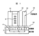
まず、図1に、従来構造の場合の概略図を示す。従来構造では、媒体対向面14までシールド13が露出しているので、その端部から磁界が漏洩する。そのため、媒体(磁気ディスク)1上の磁化信号4を消去する問題が発生する。このように、垂直記録法で用いる単磁極ヘッドでは、外部磁界16等によりノイズが発生したり、外部磁界16により主磁極12が励磁され磁界を媒体1に漏洩し信号を消去したりする問題がある。その解決方法としては、外部磁界用のシールドを設ければよいが、従来の技術では、この外部磁界用シールド13が外部磁界16を集めて媒体の磁化信号4を消去する問題や記録磁界がこのシールドに入り媒体に漏洩する問題がある。
【0015】
そこで、これらの問題の解決のためには、外部磁界用シールドを浮上面に露出させない構造をとればよいことを見出した。
【0016】
図2は、本発明による薄膜磁気ヘッドの基本的構成を示す概念図である。
【0017】
本発明の場合、媒体対向面14から外部磁界用シールド15が後退しているため、媒体1への磁界の漏洩がない。その際、主磁極12と外部磁界用シールド15のギャップ間隔(L)と媒体対向面14から外部磁界用シールド15が後退する量(T)を最適化することが、外部磁界のシールド効果と媒体への漏洩磁界の低減には重要であることが分かった。
【0018】
主磁極12と外部磁界用シールド15のギャップ間隔(L)は、0.5〜3μmが良く、媒体対向面14から外部磁界用シールド15が後退する量(T)は、0.5〜3μmが良いことが分かった。
【0019】
また、外部磁界用シールド15の大きさは、主磁極12よりも大きく、特に媒体対向面14から離れた方向での端部位置については、主磁極12の媒体対抗面14から離れた端部位置より1〜10μm(=t)大きい方がよい。大きすぎると外部磁界を集めてしまう効果が現れるためである。
【0020】
外部磁界用シールド15の材料は、例えば、NiFe、FeNi、CoNiFe等の軟磁性材料が使用できる。製造方法は、後述するように、例えば、フレームめっき法が適用できる。もちろん、スパッタ法で磁性膜を形成してからエッチングによりパターンを形成しても良い。フレームめっき法の方が、従来の磁気コア形成技術を用いて形成できるため、精度が向上する。
【0021】
図3は、本発明による薄膜磁気ヘッドを搭載する場合の磁気ディスク装置の概念を示す概略図である(ただし、図の拡大倍率は均一では無い)。磁気ディスク装置は、磁気ディスク1上に、支持体2の先端に固定された磁気ヘッド3によって磁化信号4を記録再生する。
【0022】
図4に、従来の面内記録用の記録再生分離型薄膜磁気ヘッドの概略図(ただし、図の拡大倍率は均一では無い)を示す。磁気抵抗効果膜5を利用した再生ヘッドの上に記録ヘッドが積層された構造となっている。
【0023】
図5に、従来の垂直記録用の記録再生分離型垂直記録用薄膜磁気ヘッドの概略図(ただし、図の拡大倍率は均一では無い)を示す。磁気抵抗効果膜5を利用した再生ヘッドの上に単磁極型記録ヘッドが積層された構造となっている。上述の面内記録用の磁気ヘッドとの大きな違いは、従来のヘッドの上部磁気コア7と、下部磁気コアを兼用する再生ヘッドの上部シールド11との間には、媒体対向面において、薄い(例えば、0.2μm)のギャップ膜19があったのに対し、垂直記録用磁気ヘッドでは、主磁極12と上部シールド(補助磁極)11の間のギャップ間隔20は、大きく(例えば、5〜10μm)開いていることである。
【0024】
図6に、垂直記録法の原理の概略図(ただし、図の拡大倍率は均一では無い)を示す。主磁極12からでた磁界は、記録層、裏打ち層を通り、補助磁極である上部シールド11に入る磁気回路を形成し、記録層に磁化パターン4を記録する。
【0025】
図7に、本発明の実施の形態における外部磁界用シールドを設けた垂直記録用磁気ヘッドを示す概略図(ただし、図の拡大倍率は均一ではない。)を示す。本発明における垂直記録用磁気ヘッドの基本的構成については、図2で示した通りであり、媒体対向面から後退した外部磁界用シールド15が主磁極12の上にギャップ膜(図には示していない)を介して配置されている。
【0026】
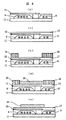
図8に、本発明による垂直記録用磁気ヘッドの製造方法の断面図を示す(ただし、図の拡大倍率は均一ではなく、再生ヘッドは省略してある)。
【0027】
(a)に、補助磁極である上部シールド11、コイル9及び主磁極12を形成したところを示す。主磁極12の材料には、CoNiFeを用いた。
【0028】
(b)に、主磁極12の上にギャップ膜17を形成したところを示す。ギャップ膜の材料にはアルミナを用い、スパッタ法で形成した。膜厚は1μmとした。
【0029】
(c)に、ギャップ膜17の上にめっき下地膜(図には示していない)を形成後、レジストフレーム18を形成したところを示す。レジストフレームには、市販のポジ型レジスト、ネガ型レジストが充分使用可能である。
【0030】
(d)に、外部磁界用シールドをめっきしたところを示す。材料は、NiFeを用い、膜厚は3μmとした。媒体対向面からの後退量(T)は1μmとした。シールドの媒体対向面から離れる方向での端部位置は、主磁極の端部位置より5μm離れた位置とした。もちろん、材料としてFeNi、CoNiFe等の他の軟磁性膜を用いても良い。
【0031】
(e)に、レジストフレームを除去して、外部磁界用シールド15を形成し、垂直記録用磁気ヘッドを完成したところを示す。今回はフレームめっき法を用いたが、磁性膜をスパッタで形成後、イオンミリングでパターン形成する方法を用いても良い。
【0032】
この垂直記録用磁気ヘッドを搭載することにより、外部磁界によるノイズ、磁化信号の消去が無く、安定性の高い垂直記録方式の磁気ディスク装置を作製できた。
【0033】
【発明の効果】
本発明によれば、媒体対向面から後退した外部磁界用のシールドを設けることにより、外部磁界によるノイズがなく、かつ、それを防止するシールドが媒体に磁界を漏洩しない垂直記録用磁気ヘッドを備えた薄膜磁気ヘッドとその作製方法を実現し、また、それを搭載した、安定性の高い磁気ディスク装置を得る。
【図面の簡単な説明】
【図1】従来の外部磁界用シールド付き垂直記録用磁気ヘッドを示す概略図。
【図2】本発明による薄膜磁気ヘッドの基本的構成を示す概念図。
【図3】本発明による薄膜磁気ヘッドを搭載する場合の磁気ディスク装置の概念を示す概略図。
【図4】従来の面内記録用磁気ヘッドを示す概略図。
【図5】従来の垂直記録用磁気ヘッドを示す概略図。
【図6】垂直記録法の原理を示す概略図。
【図7】本発明の実施の形態における外部磁界用シールド付き垂直記録用磁気ヘッドを示す概略図。
【図8】本発明における垂直記録用磁気ヘッドの製造方法の概略図。
【符号の説明】
1…媒体、2…支持体、3…磁気ヘッド、4…磁化信号、5…巨大磁気抵抗効果膜、6…電極、7…磁気コア、8…絶縁膜、9…導体コイル、10…下部シ−ルド、11…上部シ−ルド、12…主磁極、13…外部磁界用シールド、14…媒体対向面、15…外部磁界用シールド、16…外部磁界、17…ギャップ膜、18…レジストフレーム、19…ギャップ膜、20…ギャップ間隔。[0001]
BACKGROUND OF THE INVENTION
The present invention relates to a thin film magnetic head used for recording / reproduction of a magnetic disk device or the like and a magnetic disk device equipped with the same.
[0002]
[Prior art]
In a magnetic disk device, data on a recording medium is read and written by a thin film magnetic head. In order to increase the recording capacity per unit area of the magnetic disk, it is necessary to increase the surface recording density. However, the current in-plane recording method has a problem that if the recorded bit length is small, the surface recording density cannot be increased due to thermal fluctuation of the magnetization of the medium.
[0003]
In order to solve this problem, there is a perpendicular recording method in which a magnetization signal is recorded in a direction perpendicular to the medium. Also in the perpendicular recording method, a magnetoresistive head (MR head) and a giant magnetoresistive head (GMR head) having a larger reproduction output can be used for reproduction. On the other hand, it is necessary to use a single pole head for recording. Also in perpendicular recording, in order to improve recording density, it is necessary to improve track density and linear recording density. Among these, in order to improve the track density, it is necessary to make the track width of the magnetic head fine and highly accurate.
[0004]
Further, in perpendicular recording, there is a problem that noise is generated due to an external magnetic field or the like. For example, “JP-A-7-225901” describes a spike noise caused by an external magnetic field. After detecting the noise, cancel it. The problem of noise after recording is thought to be due to the fact that the magnetic domain of the main pole is unstable and the magnetic domain moves. “Outline of the 24th Annual Meeting of the Japan Society of Applied Magnetics (P161)” describes a single pole head having a shield for external magnetic field resistance.
[0005]
[Problems to be solved by the invention]
In the proposal of “Japanese Patent Laid-Open No. 7-225901”, means for detecting spike noise and avoiding errors is disclosed, and there is no description regarding noise reduction in a magnetic head. Another problem is that the main magnetic pole is excited by an external magnetic field, the magnetic field leaks to the medium, and the magnetization signal on the medium is erased.
[0006]
As a countermeasure, “24th Annual Meeting of the Japan Society of Applied Magnetics (P161)” discloses a structure in which a single magnetic pole head is provided with a shield for an external magnetic field. In this structure, the external magnetic field shield is exposed to the medium facing surface. For this reason, although the effect of preventing the external magnetic field from entering the main magnetic pole is great, the external magnetic field shield collects the external magnetic field and leaks from the medium facing surface to the medium, erasing the magnetization signal of the medium or writing the signal A problem arises. Another problem is that the magnetic field during recording leaks from the main pole and leaks to the medium via the external magnetic field shield.
[0007]
Accordingly, the present invention provides a thin-film magnetic head including a perpendicular recording magnetic head that is free from noise due to an external magnetic field and has a shield that prevents leakage of the magnetic field to a medium, a manufacturing method thereof, and a perpendicular recording magnetic head. An object of the present invention is to provide a highly stable magnetic disk device.
[0008]
[Means for Solving the Problems]
To achieve the above object, a thin film magnetic head according to the present invention has an auxiliary magnetic pole, a main magnetic pole, and an external magnetic field shield, and the end of the external magnetic field shield is against the medium facing surface. It comprises a single magnetic pole type perpendicular recording head provided at a position retracted at least from the end of the main magnetic pole.
[0009]
Further, the present invention provides a thin film magnetic head having a reproducing head using a magnetoresistive effect and a single magnetic pole type perpendicular recording head, wherein the perpendicular recording head includes an auxiliary magnetic pole, a main magnetic pole, an external magnetic field shield, A first gap film formed between the auxiliary magnetic pole and the main magnetic pole, and a second gap film formed between the main magnetic pole and the external magnetic field shield. A width of the auxiliary magnetic pole facing the gap film is larger than a width of the main magnetic pole facing the first gap film, and the end of the external magnetic field shield is at least the medium facing surface It is characterized by being provided at a position retracted from the end of the main pole.
[0010]
Further, in the above-mentioned configuration, the present invention is such that, in the above configuration, the retraction amount from the medium facing surface of the end portion of the external magnetic field shield is 0.5 to 3 μm at the portion facing the main magnetic pole, The gap formed between the external magnetic field shield and the external magnetic field shield is 0.5 to 3 μm, and the end position of the external magnetic field shield in the direction away from the medium facing surface is It is characterized by being located 1 to 10 μm away from the end position in the direction away from the medium facing surface.
[0011]
Furthermore, the present invention provides a method of manufacturing a thin film magnetic head having a perpendicular recording head comprising an auxiliary magnetic pole, a main magnetic pole, and an external magnetic field shield, wherein the external magnetic field shield is formed using a frame plating method, And providing a method of manufacturing a thin film magnetic head, comprising the step of forming the end of the external magnetic field shield so as to be at least a position retracted from the end of the main pole with respect to the medium facing surface. .
[0012]
Furthermore, according to the present invention, in a magnetic disk device configured to perform recording / reproduction on a magnetic disk by a thin film magnetic head, the thin film magnetic head has an auxiliary magnetic pole, a main magnetic pole, and an external magnetic field shield. And a magnetic pole having a single magnetic pole type perpendicular recording head, wherein the end of the shield for external magnetic field is provided at a position retracted from at least the end of the main pole with respect to the medium facing surface. Providing equipment.
[0013]
DETAILED DESCRIPTION OF THE INVENTION
Embodiments of the present invention will be described below with reference to the drawings.
[0014]
First, FIG. 1 shows a schematic diagram in the case of a conventional structure. In the conventional structure, since the
[0015]
In order to solve these problems, the present inventors have found that a structure in which the external magnetic field shield is not exposed on the air bearing surface may be employed.
[0016]
FIG. 2 is a conceptual diagram showing a basic configuration of a thin film magnetic head according to the present invention.
[0017]
In the case of the present invention, since the external
[0018]
The gap interval (L) between the main
[0019]
Further, the size of the external
[0020]
As the material of the external
[0021]
FIG. 3 is a schematic view showing the concept of a magnetic disk device when the thin film magnetic head according to the present invention is mounted (however, the magnification of the drawing is not uniform). The magnetic disk device records and reproduces the
[0022]
FIG. 4 is a schematic diagram of a conventional recording / reproducing separated type thin film magnetic head for in-plane recording (however, the magnification of the drawing is not uniform). The recording head is laminated on the reproducing head using the
[0023]
FIG. 5 is a schematic view of a conventional recording / reproducing separated type perpendicular recording thin film magnetic head for perpendicular recording (however, the magnification of the figure is not uniform). A single magnetic pole type recording head is laminated on a reproducing head using the
[0024]
FIG. 6 shows a schematic diagram of the principle of the perpendicular recording method (however, the magnification of the drawing is not uniform). The magnetic field from the main
[0025]
FIG. 7 is a schematic diagram showing a perpendicular recording magnetic head provided with an external magnetic field shield according to an embodiment of the present invention (however, the magnification of the drawing is not uniform). The basic configuration of the magnetic head for perpendicular recording in the present invention is as shown in FIG. 2, and an external
[0026]
FIG. 8 shows a cross-sectional view of a method of manufacturing a magnetic head for perpendicular recording according to the present invention (however, the magnification of the drawing is not uniform and the reproducing head is omitted).
[0027]
(A) shows a state where the
[0028]
FIG. 4B shows the
[0029]
(C) shows a state where a resist
[0030]
(D) shows the plating of the external magnetic field shield. The material was NiFe and the film thickness was 3 μm. The retraction amount (T) from the medium facing surface was 1 μm. The position of the end of the shield in the direction away from the medium facing surface was a
[0031]
(E) shows a state in which the resist frame is removed, the external
[0032]
By mounting this magnetic head for perpendicular recording, a highly stable perpendicular recording type magnetic disk apparatus without noise and erasure of magnetization signals due to an external magnetic field could be produced.
[0033]
【The invention's effect】
According to the present invention, by providing a shield for an external magnetic field receding from the medium facing surface, there is no noise due to the external magnetic field, and the shield for preventing it includes the perpendicular recording magnetic head that does not leak the magnetic field to the medium. In addition, a thin-film magnetic head and a method for manufacturing the same are realized, and a highly stable magnetic disk drive equipped with the thin-film magnetic head is obtained.
[Brief description of the drawings]
FIG. 1 is a schematic view showing a conventional perpendicular recording magnetic head with a shield for external magnetic field.
FIG. 2 is a conceptual diagram showing a basic configuration of a thin film magnetic head according to the present invention.
FIG. 3 is a schematic view showing the concept of a magnetic disk device when a thin film magnetic head according to the present invention is mounted.
FIG. 4 is a schematic view showing a conventional magnetic head for in-plane recording.
FIG. 5 is a schematic diagram showing a conventional magnetic head for perpendicular recording.
FIG. 6 is a schematic diagram showing the principle of a perpendicular recording method.
FIG. 7 is a schematic view showing a perpendicular recording magnetic head with an external magnetic field shield according to an embodiment of the present invention.
FIG. 8 is a schematic view of a method for manufacturing a magnetic head for perpendicular recording in the present invention.
[Explanation of symbols]
DESCRIPTION OF
Claims (7)
主磁極と、
前記補助磁極および前記主磁極からギャップ膜を介して全体が離間されて形成された外部磁界用シールドとを有し、
前記外部磁界用シールドの媒体対向面側の端部が、前記主磁極の媒体対向面側の端部よりも後退した位置に設けられた単磁極型垂直記録ヘッドを具備することを特徴とする薄膜磁気ヘッド。An auxiliary pole,
The main pole,
An external magnetic field shield formed entirely separated from the auxiliary magnetic pole and the main magnetic pole through a gap film ;
A thin film comprising a single magnetic pole type perpendicular recording head, wherein an end of the external magnetic field shield on the medium facing surface side is provided at a position retracted from an end of the main magnetic pole on the medium facing surface side. Magnetic head.
前記外部磁界用シールドの媒体対向面とは逆側の端部の位置が、前記主磁極の媒体対向面とは逆側の端部の位置よりも高いことを特徴とする磁気ヘッド。The magnetic head according to claim 1,
The magnetic head according to claim 1, wherein the position of the end of the external magnetic field shield opposite to the medium facing surface is higher than the position of the end of the main magnetic pole opposite to the medium facing surface.
前記補助磁極および前記主磁極からギャップ膜を介して全体が離間されて形成された外部磁界用シールドと、
前記再生ヘッドと前記外部磁界用シールドとの間に形成された単磁極型垂直記録ヘッドとを有し、
前記外部磁界用シールドの媒体対向面側の端部が、前記主磁極の媒体対向面側の端部よりも後退した位置に設けられていることを特徴とする薄膜磁気ヘッド。A reproducing head using a magnetoresistive effect;
An external magnetic field shield formed entirely separated from the auxiliary magnetic pole and the main magnetic pole through a gap film;
A single pole type perpendicular recording head formed between the read head and the external magnetic field shield;
A thin film magnetic head, wherein an end of the external magnetic field shield on the medium facing surface side is provided at a position retracted from an end of the main magnetic pole on the medium facing surface side.
前記外部磁界用シールドの媒体対向面とは逆側の端部の位置が、前記主磁極の媒体対向面とは逆側の端部の位置よりも高いことを特徴とする薄膜磁気ヘッド。The thin film magnetic head according to claim 3.
A thin film magnetic head, wherein the position of the end of the external magnetic field shield opposite to the medium facing surface is higher than the position of the end of the main magnetic pole opposite to the medium facing surface.
前記薄膜磁気ヘッドが、補助磁極と、主磁極と、前記補助磁極および主磁極からギャップ膜を介して全体が離間されて形成された外部磁界用シールドとを有し、
前記外部磁界用シールドの媒体対向面側の端部が、主磁極の媒体対向面側の端部よりも後退した位置に設けられた単磁極型垂直記録ヘッドを具備することを特徴とする磁気ディスク装置。In a magnetic disk device configured to perform recording / reproduction on a magnetic disk with a thin film magnetic head,
The thin film magnetic head has an auxiliary magnetic pole, a main magnetic pole, and an external magnetic field shield formed entirely separated from the auxiliary magnetic pole and the main magnetic pole through a gap film,
A magnetic disk comprising a single magnetic pole type perpendicular recording head, wherein an end of the external magnetic field shield on the medium facing surface side is provided at a position retracted from an end of the main magnetic pole on the medium facing surface side. apparatus.
前記外部磁界用シールドの媒体対向面とは逆側の端部の位置が、前記主磁極の媒体対向面とは逆側の端部の位置よりも高いことを特徴とする磁気ディスク装置。6. The magnetic disk device according to claim 5, wherein
2. A magnetic disk drive according to claim 1, wherein the position of the end of the external magnetic field shield opposite to the medium facing surface is higher than the position of the end of the main magnetic pole opposite to the medium facing surface.
再生に磁気抵抗効果を用いた再生ヘッドを具備してなることを特徴とする磁気ディスク装置。6. The magnetic disk device according to claim 5, wherein
A magnetic disk apparatus comprising a reproducing head using a magnetoresistive effect for reproduction.
Priority Applications (3)
| Application Number | Priority Date | Filing Date | Title |
|---|---|---|---|
| JP2001235835A JP4084008B2 (en) | 2001-08-03 | 2001-08-03 | Thin film magnetic head, method of manufacturing the same, and magnetic disk device |
| US10/068,986 US6785097B2 (en) | 2001-08-03 | 2002-02-11 | Thin film magnetic recording head, method of fabricating the thin film magnetic recording head and magnetic disk drive |
| US10/924,814 US7086140B2 (en) | 2001-08-03 | 2004-08-25 | Method of fabricating a thin film magnetic recording head |
Applications Claiming Priority (1)
| Application Number | Priority Date | Filing Date | Title |
|---|---|---|---|
| JP2001235835A JP4084008B2 (en) | 2001-08-03 | 2001-08-03 | Thin film magnetic head, method of manufacturing the same, and magnetic disk device |
Related Child Applications (1)
| Application Number | Title | Priority Date | Filing Date |
|---|---|---|---|
| JP2004227618A Division JP2004348962A (en) | 2004-08-04 | 2004-08-04 | Thin-film magnetic head and manufacturing method thereof, and magnetic disk device |
Publications (3)
| Publication Number | Publication Date |
|---|---|
| JP2003045008A JP2003045008A (en) | 2003-02-14 |
| JP2003045008A5 JP2003045008A5 (en) | 2005-05-26 |
| JP4084008B2 true JP4084008B2 (en) | 2008-04-30 |
Family
ID=19067216
Family Applications (1)
| Application Number | Title | Priority Date | Filing Date |
|---|---|---|---|
| JP2001235835A Expired - Fee Related JP4084008B2 (en) | 2001-08-03 | 2001-08-03 | Thin film magnetic head, method of manufacturing the same, and magnetic disk device |
Country Status (2)
| Country | Link |
|---|---|
| US (2) | US6785097B2 (en) |
| JP (1) | JP4084008B2 (en) |
Families Citing this family (15)
| Publication number | Priority date | Publication date | Assignee | Title |
|---|---|---|---|---|
| JP4160784B2 (en) * | 2002-05-31 | 2008-10-08 | 株式会社日立グローバルストレージテクノロジーズ | Perpendicular magnetic head and perpendicular magnetic recording / reproducing apparatus |
| JP2004022004A (en) * | 2002-06-12 | 2004-01-22 | Tdk Corp | Thin film magnetic head |
| JP3774446B2 (en) * | 2003-04-28 | 2006-05-17 | 株式会社東芝 | Perpendicular magnetic recording head and magnetic disk apparatus |
| US7554765B2 (en) * | 2003-06-11 | 2009-06-30 | Seagate Technology Llc | Magnetic head for perpendicular recording with suppressed side writing and erasing |
| JP2005018851A (en) * | 2003-06-24 | 2005-01-20 | Tdk Corp | Thin film magnetic head and magnetic recording device |
| JP2005243124A (en) | 2004-02-25 | 2005-09-08 | Hitachi Global Storage Technologies Netherlands Bv | Magnetic head, and magnetic recording/reproducing device mounting the same |
| JP2006018876A (en) * | 2004-06-30 | 2006-01-19 | Toshiba Corp | Perpendicular magnetic recording apparatus |
| JP2006018927A (en) | 2004-07-01 | 2006-01-19 | Hitachi Global Storage Technologies Netherlands Bv | Magnetic head and magnetic recording and reproducing device mounting same |
| JP4390677B2 (en) | 2004-10-15 | 2009-12-24 | ヒタチグローバルストレージテクノロジーズネザーランドビーブイ | Magnetic head and magnetic recording / reproducing apparatus equipped with the same |
| JP2006127627A (en) | 2004-10-28 | 2006-05-18 | Hitachi Global Storage Technologies Netherlands Bv | Magnetic recording and reproducing device |
| JP2006209927A (en) * | 2005-01-31 | 2006-08-10 | Toshiba Corp | Vertical magnetic head and vertical magnetic disk device |
| US7599152B2 (en) | 2005-04-28 | 2009-10-06 | Headway Technologies, Inc. | Magnetic read-write head shield that prevents flux concentration at edges close to the ABS |
| US20060245113A1 (en) * | 2005-04-28 | 2006-11-02 | Headway Technologies, Inc. | Method to reduce sensitivity of a perpendicular recording head to external fields |
| US7561379B2 (en) * | 2005-10-28 | 2009-07-14 | Seagate Technology Llc | Laminated return pole for suppressing side track erasure |
| US8385020B2 (en) | 2010-11-24 | 2013-02-26 | Headway Technologies, Inc. | Modified shield design to eliminate the far-field WATE problem |
Family Cites Families (11)
| Publication number | Priority date | Publication date | Assignee | Title |
|---|---|---|---|---|
| JPS5819717A (en) * | 1981-07-30 | 1983-02-04 | Fujitsu Ltd | Vertical magnetizing recording/reproducing head |
| DE3586827T2 (en) * | 1984-12-03 | 1993-03-25 | Olympus Optical Co | Vertical magnet head. |
| JPH0395717A (en) * | 1989-09-08 | 1991-04-22 | Fujitsu Ltd | Magnetic head |
| US5073836A (en) * | 1989-10-05 | 1991-12-17 | Hewlett-Packard Company | Single pole write and a differential magneto-resistive read for perpendicular recording |
| JPH07225901A (en) | 1994-02-10 | 1995-08-22 | Fujitsu Ltd | Vertical magnetic disk device |
| EP0935249B1 (en) * | 1996-04-12 | 2006-05-24 | Matsushita Electric Industrial Co., Ltd. | Multimedia optical disc storing both video titles provided with AV functions and video titles with no such functions which can instantly distinguish between such kinds of titles, and a reproduction apparatus and reproduction method for such disc |
| JP4297585B2 (en) * | 2000-02-28 | 2009-07-15 | 株式会社日立グローバルストレージテクノロジーズ | Magnetic recording / reproducing device |
| JP2001256608A (en) * | 2000-03-14 | 2001-09-21 | Toshiba Corp | Magnetic head, and magnetic storing/reproducing device |
| US6798615B1 (en) * | 2000-03-24 | 2004-09-28 | Seagate Technology Llc | Perpendicular recording head with return poles which reduce flux antenna effect |
| JP4102013B2 (en) * | 2000-09-22 | 2008-06-18 | 株式会社東芝 | Perpendicular recording head and perpendicular magnetic recording apparatus |
| JP2002208115A (en) * | 2000-11-10 | 2002-07-26 | Tdk Corp | Manufacturing method for thin film magnetic head |
-
2001
- 2001-08-03 JP JP2001235835A patent/JP4084008B2/en not_active Expired - Fee Related
-
2002
- 2002-02-11 US US10/068,986 patent/US6785097B2/en not_active Expired - Fee Related
-
2004
- 2004-08-25 US US10/924,814 patent/US7086140B2/en not_active Expired - Fee Related
Also Published As
| Publication number | Publication date |
|---|---|
| US20030026039A1 (en) | 2003-02-06 |
| US6785097B2 (en) | 2004-08-31 |
| US20050018346A1 (en) | 2005-01-27 |
| JP2003045008A (en) | 2003-02-14 |
| US7086140B2 (en) | 2006-08-08 |
Similar Documents
| Publication | Publication Date | Title |
|---|---|---|
| JP4102013B2 (en) | Perpendicular recording head and perpendicular magnetic recording apparatus | |
| JP4673508B2 (en) | Magnetic head and magnetic disk device | |
| JP4084008B2 (en) | Thin film magnetic head, method of manufacturing the same, and magnetic disk device | |
| KR100427731B1 (en) | Magnetic head and magnetic recording and reproducing system | |
| JP2004127480A (en) | Recording head for high density perpendicular magnetic recording | |
| JP2005038535A (en) | Perpendicular magnetic recording element, magnetic head, magnetic head device and magnetic recording and reproducing device | |
| JP2006018927A (en) | Magnetic head and magnetic recording and reproducing device mounting same | |
| US7170723B2 (en) | Magnetic disk apparatus using magnetic head having magnetoresistive film | |
| JP4160784B2 (en) | Perpendicular magnetic head and perpendicular magnetic recording / reproducing apparatus | |
| US6487042B2 (en) | Thin-film magnetic head and magnetic storage apparatus using the same | |
| JP3367877B2 (en) | Thin film magnetic head and method of manufacturing the same | |
| JP3828777B2 (en) | Magnetoresistive head | |
| JP2003045001A (en) | Magnetic recording device and magnetic head | |
| JP2004334995A (en) | Thin film magnetic head | |
| JP2005174449A (en) | Vertical magnetic recording element, thin film magnetic head, magnetic head device, and magnetic recording/reproducing device | |
| US7312957B2 (en) | Current-perpendicular-to-the-plane structure magnetoresistive element having sufficient sensitivity | |
| JP2003263705A (en) | Perpendicular recording magnetic head and magnetic disk drive on which head is mounted | |
| JPH117609A (en) | Thin film magnetic head, and recording and reproducing separation type head, and magnetic storing and reproducing device using it | |
| JP2004348962A (en) | Thin-film magnetic head and manufacturing method thereof, and magnetic disk device | |
| JP3443971B2 (en) | Magnetic recording signal reproduction method | |
| JP3573620B2 (en) | Thin film magnetic head and magnetic storage device | |
| JP2002008209A (en) | Composite thin film magnetic head | |
| JP2007115296A (en) | Magnetic head and magnetic disk apparatus | |
| JPH08180329A (en) | Magnetic head | |
| JPH1011718A (en) | Magneto-resistive head |
Legal Events
| Date | Code | Title | Description |
|---|---|---|---|
| A521 | Written amendment |
Free format text: JAPANESE INTERMEDIATE CODE: A523 Effective date: 20040804 |
|
| A621 | Written request for application examination |
Free format text: JAPANESE INTERMEDIATE CODE: A621 Effective date: 20040804 |
|
| A711 | Notification of change in applicant |
Free format text: JAPANESE INTERMEDIATE CODE: A711 Effective date: 20070125 |
|
| A977 | Report on retrieval |
Free format text: JAPANESE INTERMEDIATE CODE: A971007 Effective date: 20070222 |
|
| A131 | Notification of reasons for refusal |
Free format text: JAPANESE INTERMEDIATE CODE: A131 Effective date: 20070313 |
|
| A521 | Written amendment |
Free format text: JAPANESE INTERMEDIATE CODE: A523 Effective date: 20070511 |
|
| TRDD | Decision of grant or rejection written | ||
| A01 | Written decision to grant a patent or to grant a registration (utility model) |
Free format text: JAPANESE INTERMEDIATE CODE: A01 Effective date: 20080122 |
|
| A61 | First payment of annual fees (during grant procedure) |
Free format text: JAPANESE INTERMEDIATE CODE: A61 Effective date: 20080214 |
|
| R150 | Certificate of patent or registration of utility model |
Free format text: JAPANESE INTERMEDIATE CODE: R150 |
|
| FPAY | Renewal fee payment (event date is renewal date of database) |
Free format text: PAYMENT UNTIL: 20110222 Year of fee payment: 3 |
|
| FPAY | Renewal fee payment (event date is renewal date of database) |
Free format text: PAYMENT UNTIL: 20120222 Year of fee payment: 4 |
|
| FPAY | Renewal fee payment (event date is renewal date of database) |
Free format text: PAYMENT UNTIL: 20120222 Year of fee payment: 4 |
|
| FPAY | Renewal fee payment (event date is renewal date of database) |
Free format text: PAYMENT UNTIL: 20130222 Year of fee payment: 5 |
|
| S533 | Written request for registration of change of name |
Free format text: JAPANESE INTERMEDIATE CODE: R313533 |
|
| FPAY | Renewal fee payment (event date is renewal date of database) |
Free format text: PAYMENT UNTIL: 20130222 Year of fee payment: 5 |
|
| R350 | Written notification of registration of transfer |
Free format text: JAPANESE INTERMEDIATE CODE: R350 |
|
| FPAY | Renewal fee payment (event date is renewal date of database) |
Free format text: PAYMENT UNTIL: 20140222 Year of fee payment: 6 |
|
| R250 | Receipt of annual fees |
Free format text: JAPANESE INTERMEDIATE CODE: R250 |
|
| LAPS | Cancellation because of no payment of annual fees |