JP4083530B2 - Bent waveguide element and transmission device containing the bent waveguide element - Google Patents
Bent waveguide element and transmission device containing the bent waveguide element Download PDFInfo
- Publication number
- JP4083530B2 JP4083530B2 JP2002303111A JP2002303111A JP4083530B2 JP 4083530 B2 JP4083530 B2 JP 4083530B2 JP 2002303111 A JP2002303111 A JP 2002303111A JP 2002303111 A JP2002303111 A JP 2002303111A JP 4083530 B2 JP4083530 B2 JP 4083530B2
- Authority
- JP
- Japan
- Prior art keywords
- section
- waveguide
- cross
- bent
- change
- Prior art date
- Legal status (The legal status is an assumption and is not a legal conclusion. Google has not performed a legal analysis and makes no representation as to the accuracy of the status listed.)
- Expired - Lifetime
Links
Images

Classifications
-
- H—ELECTRICITY
- H01—ELECTRIC ELEMENTS
- H01P—WAVEGUIDES; RESONATORS, LINES, OR OTHER DEVICES OF THE WAVEGUIDE TYPE
- H01P1/00—Auxiliary devices
- H01P1/02—Bends; Corners; Twists
- H01P1/022—Bends; Corners; Twists in waveguides of polygonal cross-section
-
- H—ELECTRICITY
- H01—ELECTRIC ELEMENTS
- H01P—WAVEGUIDES; RESONATORS, LINES, OR OTHER DEVICES OF THE WAVEGUIDE TYPE
- H01P1/00—Auxiliary devices
- H01P1/20—Frequency-selective devices, e.g. filters
- H01P1/207—Hollow waveguide filters
-
- H—ELECTRICITY
- H01—ELECTRIC ELEMENTS
- H01P—WAVEGUIDES; RESONATORS, LINES, OR OTHER DEVICES OF THE WAVEGUIDE TYPE
- H01P1/00—Auxiliary devices
- H01P1/20—Frequency-selective devices, e.g. filters
- H01P1/213—Frequency-selective devices, e.g. filters combining or separating two or more different frequencies
-
- H—ELECTRICITY
- H01—ELECTRIC ELEMENTS
- H01P—WAVEGUIDES; RESONATORS, LINES, OR OTHER DEVICES OF THE WAVEGUIDE TYPE
- H01P3/00—Waveguides; Transmission lines of the waveguide type
Landscapes
- Control Of Motors That Do Not Use Commutators (AREA)
- Lubricants (AREA)
- Piezo-Electric Or Mechanical Vibrators, Or Delay Or Filter Circuits (AREA)
- Surgical Instruments (AREA)
Abstract
Description
【0001】
【発明の属する技術分野】
本発明は、曲がった導波管要素に関し、より詳細には前述の曲がった導波管要素を含有する伝達装置に関する。
【0002】
【従来の技術】
伝達装置は、10ギガヘルツ若しくはそれ以上のオーダーの高周波数を使用する。これは、例えば、周波数帯域が10ギガヘルツ若しくはより高い周波数の帯域である、衛星による伝達などの高率ラジオシステムの事例である。それらの非常に高い周波数において、信号を受信し、かかる信号の第一分離をもたらすために導波管要素を使用することは周知である。
【0003】
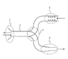
図1は周知の型の発信機/受信機装置の導波管回路を示す。ここでのアンテナは、例えば、正方形断面の導波管2へ反射波を集中させる、放物型反射器に面して置かれたホーン1である。導波管2自体は、所望のバンド幅を選択する高域フィルター機能を提供する。出力分配器3は、導波管2を、一方が受信周波数バンドでもう一方が発信周波数バンドを分離するように意図している、二つのフィルター4及び5が位置する、正方形断面の二つの導波管に分配する。フィルター4及び5の開口端部に位置するものは、マイクロストリップ技術で製造された、同軸ケーブルに電気的信号を伝えるために中間周波数バンドへ信号を転換する電子カードである。装置を簡単に製造するために、電子カードは同一面に位置される。フィルター4は導波管断面の変化の支援で単に製造される高域フィルターである。フィルター5は、例えば絞りを備えて製造された低域フィルターである。
【0004】
かかる装置は比較的規模が大きく、大量の高価な物質の使用を必要とする。これは、フィルター4が比較的長いためである。断面の変化は幾つかの段階をなし、各段階は導管の断面に関する波長の少なくとも4分の1に等しい長さを有している。加えて、断面の変化のいずれの側面においても、不連続に励起される即時消退性のモードを回避するように、導波管は導管断面と関連する波長に等しい長さを有するべきである。したがって、簡素で効果的であるが、フィルター4は一般的にフィルター5よりも長く、フィルター5をサポートする導波管が拡張されることを必要としている。
【0005】
【発明が解決しようとする課題】
本発明は導波管回路の大きさを縮減することを目的とする。曲がった部分で一定の導波管断面を維持することが必要な当業者の先入観に反して、本発明は曲がった部分で断面が変化することを提案する。したがって、本システムは、曲がった要素及び断面の変化を有する曲がった要素からなるシステムは、曲がった要素になる。
【0006】
【課題を解決するための手段】
本発明は、第一方向に沿った第一波の入力/出力及び第二方向に沿った第二波入力/出力を含有する電磁気導波管要素であり、第一方向は第二方向を切断する面内に位置し、第一及び第二入力/出力は少なくとも一つの曲がった部分で接続している。曲がった部分は、二つの端によって制限されている一定の断面の少なくとも一つの曲がった部分を含んでおり、少なくとも一つの端は導管の断面の変化に対応する。
【0007】
前述の少なくとも一つの曲がった部分の2つの端が導管の断面の変化に対応する場合、その部分の導管の中央軸の曲がった長さは、その部分の導管の断面に関連する波長の4分の1の奇数の倍数に等しい。
【0008】
非常に簡潔な実施態様によると、導管の中央軸の曲がりは、断面の変化に対応する前述の少なくとも一つの曲がった部分の端で少なくとも一つの不連続を有する。
【0009】
好ましくは、断面の変化に対応する前述の端は二つの曲がった部分間に位置している。
【0010】
本発明はまた、導波管要素を含有する伝達装置であり、その導波管要素のうちの少なくとも一つの曲がった要素は曲がった部分での導波管の断面の変化を含んでいる。
【0011】
本発明はより明かに理解され、添付図に言及する下記の記載を読み込むことでさらなる特質と利点が明かになるであろう。
【0012】
【発明の実施の形態】
図2は図1の導波管回路と同等な装置を示す。図2の回路は、フィルター4´の断面の変化が導波管の曲がった部分に移動する際に異なる。かかる変化は単純なように見えるが、しかしながら、導波管に関する数多のパラメーターを考慮しなければならない。
【0013】
導波管の断面の変化は、導波管のインピーダンスの変化に対応する。インピーダンスのこの変化は、ガイドされた波を乱すであろう波の反射を生成する。導波管の断面の著しい変化による乱れを減少するために、断面の連続した変化を活用することが周知である。連続する変化による乱れを制限するために、断面の二つの変化間に位置する導管の長さは、導管の断面に関する波長の4分の1のk倍と等しくすべきである。しかしながら、曲がった部分において、導波管の長さは、導波管の断面での波の位置に依存して、同一ではない。
【0014】
さらに、曲がった領域での波の伝播は相同ではない。任意の伝播の欠陥を回避するために、正確な伝播を保証するように曲がった部分の全体の長さに渡って一定の導波管の断面を維持することが周知である。
【0015】
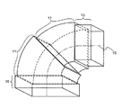
図3及び4は、本発明による曲がった導波管要素の特定の実施態様を示す。これら二つの実施態様において、この形状は発明とは関係しないので、図を乱雑にしないために外部の形状は示されずに、導波管の概略のみが斜視図で示される。例えば、かかる二つの要素は成形によって製造される二つの半要素を溶接することによって製造される。両実施態様において、導波管断面での3回の変化が使用される。
【0016】
図3の要素は、4つの導波管部分10乃至13から構成される。部分10及び13は、他の導波管要素に接合するために意図された真っ直ぐな部分である。部分11及び12は曲がった部分を形成する。部分11及び12の湾曲は、定曲率半径に対応する。各導波管部分10乃至13は一定の断面を有する。部分10の断面と部分13の断面との間で断面の緩やかな変化を作り出すように、各部分の断面は異なる。例えば、各曲がった部分11若しくは12の端は隣接する部分に関する断面の変化に対応する。部分10乃至13は端で他のものに関して中心を置かれたものである。したがって、導波管の中心を通過する曲線に対応する軸15は連続する曲線である。
【0017】
断面の変化による乱れを回避するために、断面での二つの変化の間に位置する曲がった部分は、その曲がった部分での軸15の曲がった長さが、その曲がった部分の導波管断面に関する波長に対する4分の1のk倍に等しいような規模を有し、kは奇数の整数である。
【0018】
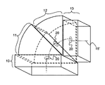
図4は、部分10乃至13が単一の端にここに縮小された共通の側を使用するためにさらにより簡素な解決策を示す。導波管の中心を通過する曲線に対応する軸15´は、導波管の断面の各変化で不連続20である。かかる不連続は主要な乱れを引き起こさないが、しかし曲がった要素のサイズを縮小することを可能にしない。
【0019】
記載されている要素でなされた測定は、乱れが曲がった部分で起こるが、しかし、かかる乱れは曲がった部分から遠隔な点では無視できることが示される。導波管に関する波長と等しい長さを有する導波管の使用は、即時消退性のモードによる乱れを除外する。得られる結果は、真っ直ぐな部分での断面の変化で得られる結果とかなり同様である。
【0020】
本発明の非常に多くの代替となる実施態様が可能である。断面での多くの変化は一様でなく、望ましくもたらされる断面でのすべての変化に依存する。例えば、断面での単一の変化がなされた場合、これは曲がった部分の境界若しくは二つの曲がった部分の間のいずれかにおいてなされるであろう。再度、断面での単一の変化がなされた場合、曲がった部分の中央軸の長さが、曲がった部分の導波管の断面と関する波長の4分の1の倍数と等しい曲がった部分を有する必要性はない。
【0021】
実際的な構造理由のために、本発明は定曲率半径を有する曲がった部分を備える長方形断面の導波管を製造する。円形若しくは楕円形断面の導波管はまた、使用される。さらに、曲がった部分で連続して変化する曲率半径を有することが可能である。
【図面の簡単な説明】
【図1】従来技術による伝達装置の導波管回路を示す。
【図2】本発明による伝達装置の導波管回路を示す。
【図3】本発明による導波管要素の実施態様を示す。
【図4】本発明による導波管要素の実施態様を示す。
【符号の説明】
1 ホーン
2 正方形断面の導波管
3 出力分配器
4 フィルター
4´ フィルター
5 フィルター
10 導波管部分
11 導波管部分
12 導波管部分
13 導波管部分
15 導波管の中心を通過する曲線に対応する軸
15´ 導波管の中心を通過する曲線に対応する軸
20 不連続[0001]
BACKGROUND OF THE INVENTION
The present invention relates to a bent waveguide element, and more particularly to a transmission device containing such a bent waveguide element.
[0002]
[Prior art]
The transmission device uses high frequencies on the order of 10 GHz or higher. This is the case for high rate radio systems such as satellite transmissions, for example, where the frequency band is 10 GHz or higher. It is well known to use waveguide elements to receive signals at these very high frequencies and provide a first separation of such signals.
[0003]
FIG. 1 shows a waveguide circuit of a known type of transmitter / receiver device. The antenna here is, for example, a horn 1 placed facing a parabolic reflector that concentrates the reflected wave onto a square-section waveguide 2. The waveguide 2 itself provides a high pass filter function for selecting a desired bandwidth. The output distributor 3 consists of two waveguides of square cross-section in which two
[0004]
Such devices are relatively large and require the use of large amounts of expensive materials. This is because the filter 4 is relatively long. The change in cross section comprises several stages, each stage having a length equal to at least one quarter of the wavelength for the cross section of the conduit. In addition, on either side of the cross-section change, the waveguide should have a length equal to the wavelength associated with the conduit cross-section to avoid discontinuously excited immediate extinguishing modes. Thus, while simple and effective, the filter 4 is generally longer than the
[0005]
[Problems to be solved by the invention]
An object of the present invention is to reduce the size of a waveguide circuit. Contrary to the prejudice of those skilled in the art who need to maintain a constant waveguide cross-section at the bend, the present invention proposes that the cross-section changes at the bend. Thus, the system is a bent element with a bent element having a bent element and a cross-sectional change.
[0006]
[Means for Solving the Problems]
The present invention is an electromagnetic waveguide element containing a first wave input / output along a first direction and a second wave input / output along a second direction, the first direction cutting the second direction. The first and second inputs / outputs are connected by at least one bent portion. The bent portion includes at least one bent portion of a constant cross section limited by two ends, at least one end corresponding to a change in the cross section of the conduit.
[0007]
If the two ends of the at least one bent portion correspond to a change in the cross section of the conduit, the bent length of the central axis of that portion of the conduit is a quarter of the wavelength associated with the cross section of the portion of the conduit. Is equal to an odd multiple of 1.
[0008]
According to a very simple embodiment, the bending of the central axis of the conduit has at least one discontinuity at the end of said at least one bent portion corresponding to a change in cross section.
[0009]
Preferably, said end corresponding to a change in cross section is located between the two bent portions.
[0010]
The present invention is also a transmission device containing a waveguide element, wherein at least one bent element of the waveguide element includes a change in the cross-section of the waveguide at the bent portion.
[0011]
The invention will be more clearly understood and further features and advantages will become apparent upon reading the following description which refers to the accompanying drawings.
[0012]
DETAILED DESCRIPTION OF THE INVENTION
FIG. 2 shows an apparatus equivalent to the waveguide circuit of FIG. The circuit of FIG. 2 differs when the cross-sectional change of the filter 4 'moves to a bent portion of the waveguide. Such changes seem simple, however, a number of parameters related to the waveguide must be considered.
[0013]
A change in the cross section of the waveguide corresponds to a change in the impedance of the waveguide. This change in impedance creates a wave reflection that would disturb the guided wave. It is well known to take advantage of continuous changes in cross-section to reduce disturbances due to significant changes in the cross-section of the waveguide. In order to limit perturbations due to successive changes, the length of the conduit located between two changes in cross section should be equal to k times one quarter of the wavelength for the cross section of the conduit. However, at the bend, the length of the waveguide is not the same, depending on the position of the wave in the cross section of the waveguide.
[0014]
Furthermore, the propagation of waves in a curved area is not homologous. In order to avoid any propagation defects, it is well known to maintain a constant waveguide cross-section over the entire length of the bend to ensure accurate propagation.
[0015]
3 and 4 show a specific embodiment of a bent waveguide element according to the invention. In these two embodiments, this shape is not relevant to the invention, so only the outline of the waveguide is shown in perspective, without the external shape being shown in order not to clutter the figure. For example, such two elements are manufactured by welding two half elements that are manufactured by molding. In both embodiments, three changes in waveguide cross section are used.
[0016]
The element of FIG. 3 is composed of four waveguide sections 10-13.
[0017]
In order to avoid turbulence due to changes in the cross section, the bent portion located between the two changes in the cross section is such that the bent length of the
[0018]
FIG. 4 shows an even simpler solution for using a common side where
[0019]
Measurements made with the elements described show that the turbulence occurs at the bend, but such turbulence is negligible at points remote from the bend. The use of a waveguide having a length equal to the wavelength for the waveguide excludes disturbances due to immediate extinguishing modes. The result obtained is quite similar to the result obtained with a cross-sectional change in the straight part.
[0020]
Numerous alternative embodiments of the present invention are possible. Many changes in cross-section are not uniform and depend on all changes in cross-section that are desirable. For example, if a single change in cross-section is made, this will be done either at the boundary of the bent part or between the two bent parts. Again, if a single change in cross-section is made, the bent portion has a central axis length equal to a quarter of the wavelength associated with the bent section of the waveguide. There is no need to have.
[0021]
For practical structural reasons, the present invention produces a rectangular cross-section waveguide with a curved portion having a constant radius of curvature. Circular or elliptical cross-section waveguides are also used. Furthermore, it is possible to have a radius of curvature that continuously changes in the bent part.
[Brief description of the drawings]
FIG. 1 shows a waveguide circuit of a transmission device according to the prior art.
FIG. 2 shows a waveguide circuit of a transmission device according to the invention.
FIG. 3 shows an embodiment of a waveguide element according to the invention.
FIG. 4 shows an embodiment of a waveguide element according to the invention.
[Explanation of symbols]
DESCRIPTION OF SYMBOLS 1 Horn 2 Waveguide 3 of square cross section 3 Output divider | distributor 4 Filter 4 '
Claims (3)
Applications Claiming Priority (2)
| Application Number | Priority Date | Filing Date | Title |
|---|---|---|---|
| FR0114251A FR2831716A1 (en) | 2001-10-30 | 2001-10-30 | BENDING GUIDE ELEMENT AND TRANSMISSION DEVICE COMPRISING SAID ELEMENT |
| FR0114251 | 2001-10-30 |
Publications (3)
| Publication Number | Publication Date |
|---|---|
| JP2003163501A JP2003163501A (en) | 2003-06-06 |
| JP2003163501A5 JP2003163501A5 (en) | 2005-11-24 |
| JP4083530B2 true JP4083530B2 (en) | 2008-04-30 |
Family
ID=8869048
Family Applications (1)
| Application Number | Title | Priority Date | Filing Date |
|---|---|---|---|
| JP2002303111A Expired - Lifetime JP4083530B2 (en) | 2001-10-30 | 2002-10-17 | Bent waveguide element and transmission device containing the bent waveguide element |
Country Status (9)
| Country | Link |
|---|---|
| US (1) | US6794962B2 (en) |
| EP (1) | EP1309030B1 (en) |
| JP (1) | JP4083530B2 (en) |
| KR (1) | KR20030035905A (en) |
| CN (1) | CN100413143C (en) |
| AT (1) | ATE472832T1 (en) |
| DE (1) | DE60236837D1 (en) |
| FR (1) | FR2831716A1 (en) |
| MX (1) | MXPA02010457A (en) |
Families Citing this family (9)
| Publication number | Priority date | Publication date | Assignee | Title |
|---|---|---|---|---|
| JP3879548B2 (en) * | 2002-03-20 | 2007-02-14 | 三菱電機株式会社 | Waveguide type demultiplexer |
| JP2004164904A (en) * | 2002-11-11 | 2004-06-10 | Nec Micro Hakan Kk | Electron tube for communication |
| JP4178265B2 (en) * | 2005-01-31 | 2008-11-12 | 株式会社村田製作所 | Waveguide horn antenna, antenna device, and radar device |
| ITTO20111108A1 (en) * | 2010-12-22 | 2012-06-23 | Selex Sistemi Integrati Spa | CALIBRATION OF ACTIVE TOWEL ANTENNAS WITH BEAM ELECTRONIC SCANNING |
| CN102832431A (en) * | 2012-08-14 | 2012-12-19 | 东南大学 | Graphene-based S-shaped waveguide |
| US9281550B2 (en) | 2013-07-16 | 2016-03-08 | L&J Engineering, Inc. | Wave mode converter |
| CN104051820B (en) * | 2014-06-30 | 2016-08-24 | 成都赛纳赛德科技有限公司 | Twist and warping waveguide |
| US9500446B2 (en) * | 2014-10-15 | 2016-11-22 | Raytheon Company | Multisegmented toroidal magnetic field projector |
| RU2718403C1 (en) * | 2019-08-15 | 2020-04-02 | Акционерное общество "Научно-производственное предприятие "Пульсар" | Angular bend of waveguide channel |
Family Cites Families (11)
| Publication number | Priority date | Publication date | Assignee | Title |
|---|---|---|---|---|
| US2673962A (en) * | 1949-01-18 | 1954-03-30 | Bell Telephone Labor Inc | Mode suppression in curved waveguide bends |
| US2649578A (en) * | 1949-12-02 | 1953-08-18 | Bell Telephone Labor Inc | Wave-guide elbow |
| US2810111A (en) * | 1950-11-25 | 1957-10-15 | Sperry Rand Corp | Wave guide corner |
| US2774945A (en) * | 1951-11-10 | 1956-12-18 | Bell Telephone Labor Inc | Methods and apparatus for transmitting circular electric waves in wave guides |
| DE2542188C3 (en) * | 1975-09-22 | 1979-04-19 | Siemens Ag, 1000 Berlin Und 8000 Muenchen | Waveguide elbow |
| DE2842577C2 (en) * | 1978-09-29 | 1984-10-04 | Siemens AG, 1000 Berlin und 8000 München | Rectangular waveguide angle piece nodulated over the broad side of the waveguide |
| DE3032644C2 (en) * | 1980-08-29 | 1982-11-25 | Georg Dipl.-Ing. Dr.-Ing. 8152 Feldkirchen-Westerham Spinner | Process for the production of rectangular waveguide bends for electromagnetic waves |
| US4564826A (en) * | 1984-04-06 | 1986-01-14 | Andrew Corporation | Multiple mitered circular waveguide bend |
| NL8501233A (en) * | 1985-05-01 | 1986-12-01 | Hollandse Signaalapparaten Bv | VERSATILE MOVABLE WAVE PIPE CONNECTION, DRIVABLE WAVE PIPE COUPLING AND ARRANGEMENT RADAR ANTENNA ARRANGEMENT. |
| IT1238534B (en) * | 1989-11-14 | 1993-08-18 | Cselt Centro Studi Lab Telecom | RIGHT ANGLE JOINT FOR RECTANGULAR WAVE GUIDES |
| EP0959516A1 (en) * | 1998-05-20 | 1999-11-24 | TRT Lucent Technologies (SA) | Methods for the manufacture of elbows for microwave guides and elbows obtained according to the method |
-
2001
- 2001-10-30 FR FR0114251A patent/FR2831716A1/en active Pending
-
2002
- 2002-10-15 KR KR1020020062799A patent/KR20030035905A/en not_active Application Discontinuation
- 2002-10-16 DE DE60236837T patent/DE60236837D1/en not_active Expired - Lifetime
- 2002-10-16 AT AT02023193T patent/ATE472832T1/en not_active IP Right Cessation
- 2002-10-16 EP EP02023193A patent/EP1309030B1/en not_active Expired - Lifetime
- 2002-10-17 JP JP2002303111A patent/JP4083530B2/en not_active Expired - Lifetime
- 2002-10-23 MX MXPA02010457A patent/MXPA02010457A/en active IP Right Grant
- 2002-10-24 CN CNB021480699A patent/CN100413143C/en not_active Expired - Lifetime
- 2002-10-30 US US10/284,840 patent/US6794962B2/en not_active Expired - Lifetime
Also Published As
| Publication number | Publication date |
|---|---|
| CN1417884A (en) | 2003-05-14 |
| ATE472832T1 (en) | 2010-07-15 |
| DE60236837D1 (en) | 2010-08-12 |
| EP1309030B1 (en) | 2010-06-30 |
| US6794962B2 (en) | 2004-09-21 |
| EP1309030A1 (en) | 2003-05-07 |
| MXPA02010457A (en) | 2003-05-07 |
| US20030080828A1 (en) | 2003-05-01 |
| FR2831716A1 (en) | 2003-05-02 |
| JP2003163501A (en) | 2003-06-06 |
| KR20030035905A (en) | 2003-05-09 |
| CN100413143C (en) | 2008-08-20 |
Similar Documents
| Publication | Publication Date | Title |
|---|---|---|
| US6906676B2 (en) | FSS feeding network for a multi-band compact horn | |
| JP2800636B2 (en) | Flexible waveguide | |
| US6166699A (en) | Antenna source for transmitting and receiving microwaves | |
| JP4083530B2 (en) | Bent waveguide element and transmission device containing the bent waveguide element | |
| US4380014A (en) | Feed horn for reflector antennae | |
| JPS58172002A (en) | 2-frequency, 2-polarized wave radio signal isolating waveguide tube | |
| JP4257225B2 (en) | Transition between microstrip and waveguide and external transmission / reception unit incorporating this transition | |
| US3560976A (en) | Feed system | |
| JP2013138401A (en) | Millimeter wave band filter | |
| US4630059A (en) | Four-port network coupling arrangement for microwave antennas employing monopulse tracking | |
| WO2004091034A1 (en) | Waveguide branching filter/polarizer | |
| US3380057A (en) | Dual band ridged feed horn | |
| EP0014692A2 (en) | Mode coupler in an automatic angle tracking system | |
| KR100852377B1 (en) | Nrd guide mode suppressor | |
| US2938179A (en) | Variable tapered waveguide transition section | |
| JPH06132710A (en) | Directional coupler | |
| US6518853B1 (en) | Wideband compact large step circular waveguide transition apparatus | |
| JP6219324B2 (en) | Planar transmission line waveguide converter | |
| US3646589A (en) | Multimode tracking system utilizing a circular waveguide having slots angularly oriented with respect to the waveguide axis | |
| GB2130444A (en) | Polarisation filter for hollow electromagnetic waveguides | |
| JP3872200B2 (en) | Non-radiative dielectric line coupler | |
| JPS6340487B2 (en) | ||
| JPH09186506A (en) | Branching filter | |
| KR101874741B1 (en) | Feed horn assembly of small parabolic antenna for multimode monopulse using tm01 mode coupler | |
| JPS6311801B2 (en) |
Legal Events
| Date | Code | Title | Description |
|---|---|---|---|
| A521 | Request for written amendment filed |
Free format text: JAPANESE INTERMEDIATE CODE: A523 Effective date: 20051012 |
|
| A621 | Written request for application examination |
Free format text: JAPANESE INTERMEDIATE CODE: A621 Effective date: 20051012 |
|
| A977 | Report on retrieval |
Free format text: JAPANESE INTERMEDIATE CODE: A971007 Effective date: 20060809 |
|
| A131 | Notification of reasons for refusal |
Free format text: JAPANESE INTERMEDIATE CODE: A131 Effective date: 20060815 |
|
| A521 | Request for written amendment filed |
Free format text: JAPANESE INTERMEDIATE CODE: A523 Effective date: 20061114 |
|
| A131 | Notification of reasons for refusal |
Free format text: JAPANESE INTERMEDIATE CODE: A131 Effective date: 20070213 |
|
| A521 | Request for written amendment filed |
Free format text: JAPANESE INTERMEDIATE CODE: A523 Effective date: 20070509 |
|
| A131 | Notification of reasons for refusal |
Free format text: JAPANESE INTERMEDIATE CODE: A131 Effective date: 20070717 |
|
| A521 | Request for written amendment filed |
Free format text: JAPANESE INTERMEDIATE CODE: A523 Effective date: 20071015 |
|
| TRDD | Decision of grant or rejection written | ||
| A01 | Written decision to grant a patent or to grant a registration (utility model) |
Free format text: JAPANESE INTERMEDIATE CODE: A01 Effective date: 20080122 |
|
| A61 | First payment of annual fees (during grant procedure) |
Free format text: JAPANESE INTERMEDIATE CODE: A61 Effective date: 20080213 |
|
| R150 | Certificate of patent or registration of utility model |
Free format text: JAPANESE INTERMEDIATE CODE: R150 Ref document number: 4083530 Country of ref document: JP Free format text: JAPANESE INTERMEDIATE CODE: R150 |
|
| FPAY | Renewal fee payment (event date is renewal date of database) |
Free format text: PAYMENT UNTIL: 20110222 Year of fee payment: 3 |
|
| FPAY | Renewal fee payment (event date is renewal date of database) |
Free format text: PAYMENT UNTIL: 20120222 Year of fee payment: 4 |
|
| FPAY | Renewal fee payment (event date is renewal date of database) |
Free format text: PAYMENT UNTIL: 20130222 Year of fee payment: 5 |
|
| FPAY | Renewal fee payment (event date is renewal date of database) |
Free format text: PAYMENT UNTIL: 20130222 Year of fee payment: 5 |
|
| FPAY | Renewal fee payment (event date is renewal date of database) |
Free format text: PAYMENT UNTIL: 20140222 Year of fee payment: 6 |
|
| R250 | Receipt of annual fees |
Free format text: JAPANESE INTERMEDIATE CODE: R250 |
|
| S111 | Request for change of ownership or part of ownership |
Free format text: JAPANESE INTERMEDIATE CODE: R313113 |
|
| S531 | Written request for registration of change of domicile |
Free format text: JAPANESE INTERMEDIATE CODE: R313531 |
|
| R371 | Transfer withdrawn |
Free format text: JAPANESE INTERMEDIATE CODE: R371 |
|
| R371 | Transfer withdrawn |
Free format text: JAPANESE INTERMEDIATE CODE: R371 |
|
| S531 | Written request for registration of change of domicile |
Free format text: JAPANESE INTERMEDIATE CODE: R313531 |
|
| R350 | Written notification of registration of transfer |
Free format text: JAPANESE INTERMEDIATE CODE: R350 |
|
| S111 | Request for change of ownership or part of ownership |
Free format text: JAPANESE INTERMEDIATE CODE: R313113 |
|
| R350 | Written notification of registration of transfer |
Free format text: JAPANESE INTERMEDIATE CODE: R350 |
|
| R250 | Receipt of annual fees |
Free format text: JAPANESE INTERMEDIATE CODE: R250 |
|
| R250 | Receipt of annual fees |
Free format text: JAPANESE INTERMEDIATE CODE: R250 |
|
| R250 | Receipt of annual fees |
Free format text: JAPANESE INTERMEDIATE CODE: R250 |
|
| EXPY | Cancellation because of completion of term |