JP4082009B2 - Turbo compressor - Google Patents
Turbo compressor Download PDFInfo
- Publication number
- JP4082009B2 JP4082009B2 JP2001290525A JP2001290525A JP4082009B2 JP 4082009 B2 JP4082009 B2 JP 4082009B2 JP 2001290525 A JP2001290525 A JP 2001290525A JP 2001290525 A JP2001290525 A JP 2001290525A JP 4082009 B2 JP4082009 B2 JP 4082009B2
- Authority
- JP
- Japan
- Prior art keywords
- stage
- impeller
- cooler
- casing
- working gas
- Prior art date
- Legal status (The legal status is an assumption and is not a legal conclusion. Google has not performed a legal analysis and makes no representation as to the accuracy of the status listed.)
- Expired - Fee Related
Links
- 238000001816 cooling Methods 0.000 claims description 62
- 239000012530 fluid Substances 0.000 claims description 16
- 239000012809 cooling fluid Substances 0.000 claims description 12
- 229910000838 Al alloy Inorganic materials 0.000 claims description 4
- 238000005266 casting Methods 0.000 claims description 4
- 238000010030 laminating Methods 0.000 claims description 4
- 210000003027 ear inner Anatomy 0.000 description 15
- 239000000498 cooling water Substances 0.000 description 13
- 239000003921 oil Substances 0.000 description 10
- 230000009467 reduction Effects 0.000 description 4
- 238000000926 separation method Methods 0.000 description 3
- 230000004323 axial length Effects 0.000 description 2
- 230000001050 lubricating effect Effects 0.000 description 2
- 238000012423 maintenance Methods 0.000 description 2
- 238000005192 partition Methods 0.000 description 2
- 238000011144 upstream manufacturing Methods 0.000 description 2
- 230000005856 abnormality Effects 0.000 description 1
- 230000008859 change Effects 0.000 description 1
- 238000010276 construction Methods 0.000 description 1
- 230000008878 coupling Effects 0.000 description 1
- 238000010168 coupling process Methods 0.000 description 1
- 238000005859 coupling reaction Methods 0.000 description 1
- 230000000694 effects Effects 0.000 description 1
- 230000006872 improvement Effects 0.000 description 1
- 238000009434 installation Methods 0.000 description 1
- 239000003562 lightweight material Substances 0.000 description 1
- 239000010687 lubricating oil Substances 0.000 description 1
- 239000000463 material Substances 0.000 description 1
- 238000000034 method Methods 0.000 description 1
- 238000004881 precipitation hardening Methods 0.000 description 1
- 230000008569 process Effects 0.000 description 1
- 239000010935 stainless steel Substances 0.000 description 1
- 229910001220 stainless steel Inorganic materials 0.000 description 1
- XLYOFNOQVPJJNP-UHFFFAOYSA-N water Substances O XLYOFNOQVPJJNP-UHFFFAOYSA-N 0.000 description 1
Images


Classifications
-
- F—MECHANICAL ENGINEERING; LIGHTING; HEATING; WEAPONS; BLASTING
- F04—POSITIVE - DISPLACEMENT MACHINES FOR LIQUIDS; PUMPS FOR LIQUIDS OR ELASTIC FLUIDS
- F04D—NON-POSITIVE-DISPLACEMENT PUMPS
- F04D25/00—Pumping installations or systems
- F04D25/16—Combinations of two or more pumps ; Producing two or more separate gas flows
- F04D25/163—Combinations of two or more pumps ; Producing two or more separate gas flows driven by a common gearing arrangement
-
- F—MECHANICAL ENGINEERING; LIGHTING; HEATING; WEAPONS; BLASTING
- F04—POSITIVE - DISPLACEMENT MACHINES FOR LIQUIDS; PUMPS FOR LIQUIDS OR ELASTIC FLUIDS
- F04D—NON-POSITIVE-DISPLACEMENT PUMPS
- F04D17/00—Radial-flow pumps, e.g. centrifugal pumps; Helico-centrifugal pumps
- F04D17/08—Centrifugal pumps
- F04D17/10—Centrifugal pumps for compressing or evacuating
- F04D17/12—Multi-stage pumps
-
- F—MECHANICAL ENGINEERING; LIGHTING; HEATING; WEAPONS; BLASTING
- F04—POSITIVE - DISPLACEMENT MACHINES FOR LIQUIDS; PUMPS FOR LIQUIDS OR ELASTIC FLUIDS
- F04D—NON-POSITIVE-DISPLACEMENT PUMPS
- F04D29/00—Details, component parts, or accessories
- F04D29/58—Cooling; Heating; Diminishing heat transfer
- F04D29/582—Cooling; Heating; Diminishing heat transfer specially adapted for elastic fluid pumps
- F04D29/5826—Cooling at least part of the working fluid in a heat exchanger
Description
【0001】
【発明の属する技術分野】
本発明は、工場の動力空気源やプロセスに使用されるターボ圧縮機に関し、特に3段に構成されたものに好適なターボ圧縮機に関する。
【0002】
【従来の技術】
一般産業分野で使用される汎用空気圧縮機では、価格低減や建屋コストの削減および保守の容易性等の要求からターボ圧縮機を小型化することが強く望まれている。圧縮機の流体性能の要求は、所定の吸込み流量において所定の吐出し圧力を達成することである。この要求を満足するためには、動力損失を低減して内部流体の流速を所定速度以下に抑える必要がある。圧縮機の他の要求として、インタークーラで発生したドレンがインタクーラの出口側から次段の圧縮機へ吸込まれるのを防止することがある。この要求を満足するためには、インタークーラ出口流速を所定速度以下に抑える必要がある。このような要求は圧縮機の大型化に結びつく。
【0003】
このような圧縮機の小型化に反する要求の下で圧縮機を小型化するために、従来のターボ圧縮機では例えば特開平8-93685号公報に記載のように、ターボ圧縮機の各構成要素の配置を工夫してターボ圧縮機をコンパクト化している。この公報に記載のものは、駆動モータの出力軸に歯車装置を介して回転軸を平行に配置している。そして、回転軸の両側に第1段圧縮機と第2段圧縮機とを連結している。さらに駆動モータ側に第1段圧縮機を、その反対側に第2段圧縮機を配置し、駆動モータの側方に第1段圧縮機の吸入管及び吸入フィルタを配置している。
【0004】
【発明が解決しようとする課題】
上記従来技術の項で述べた特開平8-93685号公報に記載のものは、確かにコンパクト化されているものの2段機であり、高圧力が望まれるまたはより高効率が期待できる3段機を採用したときに圧縮機をいかに小型化するかについては考慮されていない。したがって、多段圧縮機を3段機で構成したときの圧縮機の組み立てや分解の容易さ、作業性の向上については全く考慮されていない。
【0005】
本発明は上記従来技術の不具合に鑑みなされたものでありその目的は、3段に構成されたターボ圧縮機をコンパクト化するととともに、組立てや分解を容易にすることにある。
【0006】
【課題を解決するための手段】
上記目的を達成するための本発明の特徴は、駆動モータの出力軸に接続され第1の歯車手段を有する回転軸(15s)と、この回転軸に平行に配置され前記歯車手段と噛み合う第2および第3の歯車手段を有する第1および第2の回転軸とを有し、第1の回転軸の反モータ側にアルミニウム合金製の第1段羽根車を、モータ側に第2段羽根車を取付け、第2の回転軸の反モータ側に第3段羽根車を取付け、作動ガスを第1段羽根車から第2段羽根車、次いで第3段羽根車へと導く3段形のターボ圧縮機において、前記第1段羽根車で圧縮された作動ガスを冷却する第1のクーラと、前記第2の羽根車で圧縮された作動ガスを冷却する第2のクーラと、前記第3の羽根車で圧縮された作動ガスを冷却する第3のクーラと、この第1ないし第3のクーラを収容するとともに前記第1段ないし第3段の羽根車を収容する一体ケーシングとを備え、この一体ケーシングに前記第1段ないし第3段羽根車で圧縮された作動ガスを前記第1ないし第3のクーラに直接導く流路を形成し、この第1ないし第3のクーラは、この一体ケーシングに区画された各冷却室に収容されて前記回転軸(15s)と略直角方向に順に並べられたコルゲートフィン型のクーラであって、前記第1段ないし第3段羽根車の下方に配置されており、前記一体ケーシングは前記第1段ないし第3段羽根車と、前記回転軸(15s)、第1および第2の回転軸とを収容しており、前記各クーラにおける流れは、前記各冷却室内のクーラの一方の側面部から流入し他方の側面部から流出する横方向の流れとしたものである。
【0007】
そしてこの特徴において、第1の回転軸にスラストカラーを装着し、ケーシングに軸受とステージラビリンスと油切ラビリンスとを設け、スラストカラーの外径よりも、軸受のハウジングの外径とステージラビリンスのインロー径と油切ラビリンスのインロー径を大きくし、第1の回転軸を一体ケーシングに保持したまま第1段羽根車は取り外し可能であり、さらに第1の回転軸に第2段羽根車を取付けたまま第1の回転軸を一体ケーシングから取り外し可能にするのがよく、各クーラは、冷却流体と被冷却流体とが流れる層を交互に積層したものであり、各層を流れる冷却流体と被冷却流体の流れ方向は略直交しており、積層方向の端部の層は冷却流体が流れる層であるのがよい。また、冷却流体と被冷却流体の流れ方向をほぼ水平方向にし、冷却室を形成する一体ケーシングの各クーラに対向する面にシールゴムを保持する溝を設け、各クーラの上面または下面と一体ケーシングとの間をシールゴムでシールするのがよく、一体ケーシングを鋳物で形成するのがよい。
【0008】
また好ましくは、前記各クーラは、冷却流体と被冷却流体とが流れる層を交互に積層したものであり、各層を流れる冷却流体と被冷却流体の流れ方向は略直交しており、積層方向の端部の層は冷却流体が流れる層であり、冷却流体と被冷却流体の流れ方向をほぼ水平方向にし、冷却室を形成する前記一体ケーシングの各クーラに対向する面にシールゴムを保持する溝を設け、前記各クーラの上面または下面と前記一体ケーシングとの間をシールゴムでシールするようにしてもよい。さらに、前記第1段羽根車の吸込み側にインレットガイドベーン装置を取付けてもよく、前記一体ケーシングを鋳物で形成するのがよい。
【0010】
上記目的を達成するための本発明の他の特徴は、モータ軸に接続された回転軸(15s)と、第1段羽根車と第2段羽根車を両端部に取付けた第1の回転軸と、第3段羽根車を一方端に取付けた第2の回転軸とを平行に配置し作動ガスを第1段羽根車から第2段羽根車、次いで第3段羽根車へと導く3段形のターボ圧縮機において、前記各段の羽根車及び各回転軸を収容する一体ケーシングを有し、この一体ケーシングの各段の羽根車部において第1、第2の回転軸の軸方向に円形のフランジ開口部を有し、該開口部から各段の羽根車を取り外し可能にし、前記各段の羽根車を収容する一体ケーシングはその下部に各段の羽根車で圧縮された作動ガスを冷却するコルゲートフィン型のクーラを収容するとともに、この一体ケーシングに前記第1段ないし第3段羽根車で圧縮された作動ガスを前記クーラに直接導く流路を形成し、各クーラにおける作動ガスの流れ方向が、クーラの一方の側面部から流入し他方の側面部から流出する横方向の流れとなるように、各クーラを一体ケーシングの区画された各冷却室に収容し、ケーシングの前記クーラを収容した部分の軸直角方向長さ以内に圧縮機の各部を収容したものである。
【0012】
【発明の実施の形態】
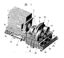
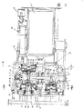
本発明の一実施例を、図面を用いて説明する。図1は、本発明に係るターボ圧縮機の全体斜視図であり、図2は図1に示したターボ圧縮機の平面図、図3は図2のA−A断面図、図4は図2のB−B断面図でありそれぞれ矢印側から見た図、図5は図3のC−C断面図である。本発明に係るターボ圧縮機は、3段の圧縮機段を有している。
【0013】
モータベース71の上には、このモータベース71と略同じ幅を有するモータ1が載置されている。モータベース71は油タンクを兼用しており、後述する各圧縮機段の潤滑部や増速歯車段を潤滑するための潤滑油を収容している。モータ1の一方側にはモータ軸2が延在しており、圧縮機本体100がカップリング2aにより接続されている。圧縮機本体100は、第1段圧縮機6、第2段圧縮機7および第3段圧縮機8を有している。各段の圧縮機のケーシングは、第1のインタークーラ30xと第2のインタークーラ40xとアフタークーラ50xとを形成する箱体状の冷却室25のケーシングと一体化されている。
【0014】
図2に示したように、駆動モータ1の出力軸2は歯車装置3の回転軸15sに接続されている。歯車装置3は、中央部に大歯車15が形成された回転軸15sと、この大歯車15に噛み合う小歯車4、5が形成された第1、第2の回転軸4s、5sとを有している。第1の回転軸4sは、小歯車4の両側を軸受10で支承されており、第2の回転軸5sは小歯車5の両側を軸受11で支承されている。第1及び第2の回転軸4s、5sは、それぞれ回転軸15sに平行に配置されている。
【0015】
第1の回転軸4sの両端部には、第1段圧縮機6の羽根車と第2段圧縮機7の羽根車とが取付けられている。第1段圧縮機6は反駆動モータ1側であり、第2段圧縮機7は駆動モータ1側である。第2の回転軸の一方端には第3段圧縮機8の羽根車が取付けられている。作動ガスの配管経路を簡素化するために、本実施例では第3段圧縮機を反駆動モータ1側に配置している。
【0016】
第1段圧縮機は、第1の回転軸に取付けた羽根車6b、静止流路の羽根チップ側を形成するダイアフラム6c、およびこのダイヤフラム6cとともに静止流路の羽根心板側を形成するスクロールケーシング6aを有している。ダイヤフラム6cと羽根車6bとは、スクロールケーシング6aに内蔵されている。第1段圧縮機の羽根車6bよりも上流側には、インレットガイドベーン装置9が配置されている。
【0017】
第2段圧縮機は、羽根車7bと、静止流路の羽根チップ側を形成するダイアフラム7cと、これら羽根車7bとダイアフラム7cとを収容し、静止流路の羽根心板側を形成するスクロールケーシング7aと、吸込み側静止流路を形成するエンドプレート7eとを有している。同様に、第3段圧縮機は、羽根車8bと、静止流路の羽根チップ側を形成するダイアフラム8cと、これら羽根車8bとダイアフラム8cとを収容し、静止流路の羽根心板側を形成するスクロールケーシング8aと、吸込み側静止流路を形成するエンドプレート8eとを有している。各段の圧縮機内を流れる作動流体は、各段羽根車の心板の背面側に設けられたステージラビリンス6d、7d、8dにより減速機3側へ漏れて流入するのを防止されている。なお、各段圧縮機のスクロールケーシング6a、7a、8aは、ギアケーシング3aと一体の鋳物で構成されている。
【0018】
このように構成した本実施例では、以下のように各段の圧縮機を組み立てる。一端側が開放されたスクロールケーシング6a、7a、8aを、減速装置3部のケーシングに取付ける。次に、第1の回転軸4sの両端部に羽根車6b、7bを取付ける。この際、第1段圧縮機で詳細を示すように、第1の回転軸4sに締結ボルト4bを埋め込み、羽根車6bを第1の回転軸4sに嵌合した後、締結ボルト4bにナット4cを締結し、所定のトルクで締める。なお、第1の回転軸4sは、軸端部に締付けボルト部とインロー部とが形成されている。一方、羽根車6bの中心部には、軸方向に延びるインロー部(穴)が形成されている。羽根車6bのインロー部の軸方向長さは、これに嵌合する第1の回転軸4sの外半径相当である。そして、第1段羽根車をアルミニウム合金製として、第1の回転軸への着脱を容易にしている。第2段圧縮機も同様の構成としている。第3段圧縮機については、第2の回転軸5sの一方端部に羽根車8bを図示しないボルト及びナットを用いて取付ける。
【0019】
次に、各段のダイアフラム6c、7c、8cを、それぞれのスクロールケーシング6a、7a、8aの開放端側から、軸方向に嵌合する。第1段圧縮機の場合には、この状態で、ダイアフラム6cの外径端側に形成したフランジ部をボルト締結する。第2段圧縮機及び第3段圧縮機では、さらにエンドプレート7e、8eをダイアフラム7c、8cの開放端側から嵌合し、エンドプレート7e、8eの外径端部に形成したフランジ部をボルト締結する。ここで、第1の回転軸に装着され小歯車4の両側に配置されたスラストカラー4aの外径よりも、第1の回転軸を支承する軸受10のハウジング外径、羽根車の心板背面側に配置したステージラビリンス6dのスクロールケーシング6aへの取付け部外径(インロー径)、および軸受10とステージラビリンス6dとの軸方向中間部に設けられた油切ラビリンス12の外径(インロー径)の方を大きくしている。これらの径の大小関係は、第2段圧縮機および第3段圧縮機についても同様である。
【0020】
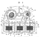
図3に、第1段圧縮機と第3段圧縮機及び各クーラへの作動ガス流路を横断面図で示す。同様に、図4に第2段圧縮機と各クーラへの作動ガス流路を横断面図で示す。第1段圧縮機、第2段圧縮機、第3段圧縮機及び歯車装置の下方に、内部が駆動モータ1の幅方向に3つに仕切られた略直方体の箱体5を設けている。各仕切り部は、冷却室を形成する。図3で最も左側の冷却室25aには、第1段圧縮機から吐出された作動ガスを冷却して第2段圧縮機へ導くインタークーラ30が収容されている。この冷却室25aの右隣の冷却室25bには、第2段圧縮機から吐出された作動ガスを冷却して第3段圧縮機へ導くインタークーラ40が収容されている。さらに隣の冷却室25cには、第3段圧縮機から吐出された作動ガスを冷却して排気するアフタークーラ50が収容されている。
【0021】
この図3において、第1段羽根車6bに吸込まれた流体は圧縮されて、ダイアフラム6cとスクロールケーシング6aで形成された静止流路を流れ、略最左側に配置された吐出ノズル20から最も左側の冷却室25aに導かれる。そして冷却室25a内に配置されたクーラ30の側面部(図3の左側の面)からクーラ30に流入し、クーラ30の右側面部から流出する。クーラ30を出た作動ガスは図3の背面側でまとめられ、図4に詳細を示すように、冷却室25aに接続された第2段吸込みノズル21から第2段羽根車7bに吸込まれる。
【0022】
ここで、図4中の第2段圧縮機の断面は、右半分が吸込みダイアフラム部であり、左半分が吐出スクロール部断面である。第2段圧縮機の吸込みノズル21から吸込まれた作動ガスは、第2段圧縮機の羽根車7bで圧縮された後、ダイアフラム7cとスクロールケーシング7aで形成された静止流路を流れ、吐出ノズル22から中央の冷却室25bに導かれる。そして冷却室25b内に配置されたクーラ40の右側面部からクーラ40に流入し、クーラ40の左側面部から流出する。クーラ40を出た作動ガスは図4の背面側でまとめられ、図3に詳細を示すように、冷却室25bに接続された第3段吸込みノズル23から第3段羽根車8bに吸込まれる。
【0023】
図3中の第3段圧縮機の断面は、右半分が吸込みダイアフラム部であり、左半分が吐出スクロール部断面である。第3段圧縮機の羽根車8bで圧縮された作動ガスは、ダイアフラム8cとスクロールケーシング8aで形成された静止流路を流れ、吐出ノズル24から右側の冷却室25cに導かれる。そして冷却室25c内に配置されたクーラ50の左側面部からクーラ50に流入し、クーラ50の右側面部から流出する。クーラ50を出た作動ガスは図3の背面側でまとめられ、冷却室25cの上面に設けられたガス排出孔61(図2参照)から需要元へ送られる。したがって、第1段圧縮機の吸込み部分を除き、各段の吸込み流れおよび吐出流れはいずれも半径方向流れとなっている。なお、図3及び図4では作動ガスの流れを矢印で示しいてる。
【0024】
図5に冷却室を形成する箱体25と各ノズル及びクーラの位置関係を示す。この図5は図3のC−C断面矢視図である。第1段圧縮機で圧縮された作動ガスは、上述したように、吐出ノズル20から第1の冷却室25aに入る。その際、冷却室25aの前部(反モータ側)に設けた孔20aから冷却室25aに入る。第1のクーラ(インタークーラ)30で冷却された後、冷却室25aの後部(モータ側)に設けられた孔21aから流出する。第2段圧縮機で圧縮された作動ガスは、第2の冷却室25bの後部(モータ側)に設けられた孔22aから冷却室25bに流入する。第2のクーラ(インタークーラ)40で冷却された作動ガスは、冷却室25bの前部(反モータ側)に設けた孔23aから流出する。
【0025】
第3段圧縮機で圧縮された作動ガスは、第3の冷却室25c前部(反モータ側)に設けられた孔24aから冷却室に流入する。そして、第3のクーラ(アフタークーラ)50で冷却された後、冷却室25cの後部(モータ側)に設けた孔60から流出する。このような流れとするために、各段の吸込み部及び吐出部との接続部は、全て冷却室の上面に設けている。したがって、各段の吸込みノズル、吐出ノズルおよび略箱体の冷却室は、圧縮機スクロールケーシング及びギアケーシングと一体化できる。
【0026】
図3に示すように、略直方体の冷却室の上面側および下面側には、シール溝25d〜25iが形成されている。このシール溝25d〜25iに、各クーラ側のシール部品31、32、41、42、51、52を係合させて、圧縮された高温の作動ガスが下流側へ流入するのを防止している。各クーラ30、40、50の背面側には、冷却水リターンヘッダ33、43、53が形成されている。冷却水リターンヘッダ33、43、53と各クーラ30、40、50との間にはシール部品34、44、54が装着されている。なお、シール部品としてはゴム材が好適である。
【0027】
各クーラ30、40、50には冷却水が通水しており、各段の羽根車6b、7b、8bで圧縮された作動ガスと熱交換して冷却する。冷却水の流れは、作動ガスの流れに略直交しており、図5の下側から各クーラ30、40、50に冷却水が導かれ、冷却水リターンヘッダ33、43、53で180度向きを変えて再び各クーラ30、40、50に流入する。そして、図5の下側へ排出される。これら各クーラへ流れる冷却水は、冷却水集合配管81から供給され、冷却水供給配管82でまとめられて図示しない冷却塔へと導かれる(図1参照)。なお、各クーラをコルゲートフィン型熱交換器とすると、クーラ全体の小型化が可能になる。
【0028】
冷却水リターンヘッダ33、43、53には、各クーラの下面から僅かに突出してローラ35、45が設けられている。これにより、各クーラを組込むときや各クーラを抜出す時に、各クーラが冷却室に接触するのを防止でき、またシール部品の溝への保持を適正にしている。なお、図3や図4に示したように各冷却室25a〜25cはクーラを保持する冷却室の上面側及び下面側に設けたシール溝が形成されたステー部とクーラによって左右の2つの部分に分けられる。そこでこのステー部の位置を、次のように設定する。図3で各冷却室の左側部分に当たる入口側の部分が、その右側に当たる出口側の部分以上の軸直角断面積を有するようにする。このときクーラの部分は冷却室の断面積から省く。また、圧縮機全体をコンパクトにするため、出口側と入口側の軸直角断面積比を、第3の冷却室25c、第2の冷却室25b、第1の冷却室25aの順に大きくする。
【0029】
本実施例によれば、1)第1段羽根車を回転軸に装着したままケーシングに着脱可能となる。そして第1段羽根車を反モータ側に配置したので、第1段の大径のスクロールとモータの駆動軸との干渉を防止できる。また、第2段のスクロール径は第1段のスクロール径より小さくできるから、圧縮機全体を小型化できる。さらに、モータの無い側に第1段圧縮機を設けたので、第1段羽根車の上流側に配置されるインレットガイドベーンの取付けが容易なるとともに、第1段羽根車の着脱が容易になる。
【0030】
2)回転軸に装着されたスラストカラーの外径よりも、軸受のハウジング外径とステージラビリンスのインロー径と油切ラビリンスのインロー径を大きくしたので、第1段羽根車を取外した後に、第1の回転軸も軸方向に抜出し可能となった。
【0031】
3)第1段の吸込み部を除いて、各段の吸込み部及び吐出部が半径方向を向くようにしたので、半径方向ノズルの開口部を冷却室の上面に容易に接続できる。その結果、各クーラと各段の圧縮機とを結ぶ流路の長さを低減でき、流体損失を低減できる。
【0032】
4)各冷却室の出口側と入口側の軸直角断面積比を1以上にしたので、クーラ出口側のガス流速を低下させ、凝縮したドレンを自由落下により分でき、分離離効率が向上する。また面積比を第3、第2、第1冷却室の順に大きくしたので、冷却室の大きさをコンパクトにできる。さらに、第1段圧縮機の流速を第3段圧縮機並みに低減することができ、ドレン分離効率を向上できる。
【0033】
5)両端部に羽根車を装着した回転軸の羽根車間に、増速歯車装置と軸受と軸封装置のみが必須であるから、羽根車間距離をクーラの長さより短くでき、クーラ上に羽根車を配置する構造が可能になる。逆にいえば、クーラを両羽根車間距離程度まで小形化でき、クーラケースと圧縮機ケーシングを繋ぐ流路の形成を容易にできる。
【0034】
6)クーラの両端部を冷却水ヘッダまたは冷却水室としたので、高温の作動ガスの漏れ防止にゴムシールを用いることが可能になった。
【0035】
7)第1の回転軸を圧縮機に取付けたまま第1段羽根車を取外せるので、第1の回転軸に第2段羽根車を取付けたまま第1の回転軸をモータ側に抜出すことが可能になった。また、第2の回転軸に第3段圧縮機の羽根車を取付けたまま、反モータ側に第2の回転軸を抜出せるので、組立て分解が容易になる。
【0036】
8)羽根車背面にステージラビリンスを設け、ラビリンスのインロー部の径を回転軸のスラストカラー外径より大きくし、ギアケーシングと上ケーシング部にはラビリンスの軸方向長さより長い空間部を設けたので、ラビリンスを歯車装置側から圧縮機スクロールケーシングに装着または着脱が可能になった。
【0037】
9)冷却室に装着するクーラの構造を以下のようにする。すなわち、冷却側と被冷却側の2つの作動流体が仕切板を隔てて直交する。その際、冷却側の流体が流れる層と被冷却側の流体が流れる層を交互に複数層積層し、積層方向の両側端は冷却側となるように構成する。ぞして各クーラは全体としてコルゲートフィン型熱交換器となっている。これにより、プレート形熱交換器よりも2倍程度の高性能となり、コンパクトで高効率な熱交換器をターボ圧縮機に採用できる。
【0038】
なお、上記実施例において、各クーラを共通化することも可能である。その場合、異常が発生したときのための予備の部品数を低減できる。また、第1段圧縮機の羽根車は他の段の羽根車に比べて大径になるので、羽根車によるオーバーハング量を低減するために軽量材料とすることが望ましい。そのため本実施例ではアルミ合金を用いている。第2段目以降の羽根車には、クーラで冷却されて水分が凝縮した作動ガスが流入するので、析出硬化型ステンレス鋼を用いるのが望ましい。
【0039】
【発明の効果】
以上述べたように本発明によれば、第1段圧縮機と第2段圧縮機と第3段圧縮機とを歯車装置やクーラを収容する冷却室までをも含めて一体ケーシング化し羽根車を軸方向に取り外し可能にしたので、3段のターボ圧縮機を装置全体をコンパクトにできる。また、ターボ圧縮機を小型化したので、据付面積も低減できる。さらにケーシングの一体化により、建設工事やメンテナンスが容易になる。
【図面の簡単な説明】
【図1】本発明に係るターボ圧縮機の一実施例の斜視図。
【図2】図1に示したターボ圧縮機の正面図。
【図3】図2のA−A断面図。
【図4】図2のB−B断面図。
【図5】図3のC−C断面図。
【符号の説明】
1・・・駆動モータ、2・・・駆動軸、3・・・歯車増速、4・・・第1の回転軸、4a、5a・・・スラストカラー、5・・・第2の回転軸、6・・・第1段圧縮機、7・・・第2段圧縮機、8・・・第3段圧縮機、6a、7a、8a・・・圧縮機ケーシング、6b、7b、8b・・・羽根車、6c、7c、8c・・・ダイアフラム、6d、7d、8d・・・ステージラビリンス、9・・・インレットガイドベーン装置、10・・・軸受、11・・・軸受、12、13、14・・・油切ラビリンス、20・・・第1段吐出ノズル、20a、21a、22a、23a、24a・・・ノズル開口部、21・・・第2段吸込みノズル、22・・・第2段吐出ノズル、23・・・第3段吸込みノズル、24・・・第3段吐出ノズル、25・・・冷却室、25a・・・第1の冷却室、25b・・・第2の冷却室、25c・・・第3の冷却室、25d〜25i・・・冷却室上面下面のシール溝、30・・・インタークーラ、30x・・・第1のクーラ、30a・・・ガス室、30b・・・冷却水室、31、32・・・シール部品、33・・・冷却水リターンヘッダ、34・・・シール部品、35・・・ローラ、39・・・ドレン排出孔、40x・・・第2のクーラ、49・・・ドレン排出孔、50x・・・第3のクーラ、59・・・ドレン排出孔、60・・・ガス排出孔、71・・・オイルタンク兼モータベース、72・・・主オイルポンプ、73・・・起動ポンプ、74・・・オイルクーラ、75・・・給油温度調節弁、76・・・オイルフィルタ。[0001]
BACKGROUND OF THE INVENTION
The present invention relates to a turbo compressor used in a factory power air source and process, and more particularly to a turbo compressor suitable for a three-stage configuration.
[0002]
[Prior art]
In general-purpose air compressors used in the general industrial field, it is strongly desired to reduce the size of turbo compressors because of demands such as price reduction, building cost reduction, and ease of maintenance. The compressor fluid performance requirement is to achieve a given discharge pressure at a given suction flow rate. In order to satisfy this requirement, it is necessary to reduce the power loss and keep the flow rate of the internal fluid below a predetermined speed. Another requirement of the compressor is to prevent the drain generated in the intercooler from being sucked into the next stage compressor from the outlet side of the intercooler. In order to satisfy this requirement, it is necessary to keep the intercooler outlet flow velocity below a predetermined speed. Such a requirement leads to an increase in the size of the compressor.
[0003]
In order to reduce the size of the compressor under demands contrary to the downsizing of the compressor, in the conventional turbo compressor, for example, as described in JP-A-8-93685, each component of the turbo compressor The turbo compressor is made compact by devising the arrangement of In the device described in this publication, the rotation shaft is arranged in parallel to the output shaft of the drive motor via a gear device. And the 1st stage compressor and the 2nd stage compressor are connected with the both sides of the rotating shaft. Further, the first stage compressor is disposed on the drive motor side, the second stage compressor is disposed on the opposite side, and the suction pipe and the suction filter of the first stage compressor are disposed on the side of the drive motor.
[0004]
[Problems to be solved by the invention]
The one described in Japanese Patent Application Laid-Open No. 8-93685 described in the section of the above-mentioned prior art is a two-stage machine that is surely made compact, but a three-stage machine where high pressure is desired or higher efficiency can be expected. It is not considered how to reduce the size of the compressor when adopting. Accordingly, no consideration is given to the ease of assembly and disassembly of the compressor and the improvement of workability when the multi-stage compressor is composed of three stages.
[0005]
The present invention has been made in view of the above problems of the prior art, and an object of the present invention is to make a turbo compressor configured in three stages compact and to facilitate assembly and disassembly.
[0006]
[Means for Solving the Problems]
In order to achieve the above object, the present invention is characterized in that a rotary shaft (15s) connected to the output shaft of the drive motor and having a first gear means, and a second gear which is arranged in parallel to the rotary shaft and meshes with the gear means. And first and second rotating shafts having third gear means, a first stage impeller made of aluminum alloy on the side opposite to the motor of the first rotating shaft, and a second stage impeller on the motor side. A third stage impeller mounted on the side opposite to the motor of the second rotating shaft, and a three-stage turbo that guides working gas from the first stage impeller to the second stage impeller and then to the third stage impeller In the compressor, a first cooler that cools the working gas compressed by the first impeller, a second cooler that cools the working gas compressed by the second impeller, and the third cooler A third cooler for cooling the working gas compressed by the impeller, and the first to third coolers; And an integral casing for accommodating the first to third stage impellers, and the working gas compressed by the first to third stage impellers in the integral casing. A flow path that directly leads to the third cooler is formed, and the first to third coolers are housed in the respective cooling chambers partitioned by the integral casing, and are sequentially in a direction substantially perpendicular to the rotation shaft (15s). Arranged corrugated fin type coolers, which are arranged below the first to third stage impellers, and the integral casing includes the first to third stage impellers and the rotating shaft ( 15s), the first and second rotating shafts are accommodated, and the flow in each cooler flows in the lateral direction from one side surface of the cooler in each cooling chamber and out from the other side surface. It is what.
[0007]
In this feature, a thrust collar is mounted on the first rotating shaft, a bearing, a stage labyrinth, and an oil drain labyrinth are provided on the casing. The outer diameter of the bearing housing and the inlay of the stage labyrinth are larger than the outer diameter of the thrust collar. The first stage impeller can be removed while the first rotary shaft is held in the integrated casing, and the second stage impeller is attached to the first rotary shaft. It is preferable that the first rotating shaft can be removed from the integral casing without any change, and each cooler is formed by alternately laminating layers through which the cooling fluid and the fluid to be cooled flow, and the cooling fluid and the fluid to be cooled flowing through each layer. The flow directions are substantially orthogonal, and the layer at the end in the stacking direction is preferably a layer through which the cooling fluid flows. In addition, the flow direction of the cooling fluid and the fluid to be cooled is substantially horizontal, and a groove for holding the seal rubber is provided on the surface facing each cooler of the integrated casing forming the cooling chamber, and the upper or lower surface of each cooler and the integrated casing A gap between the gaps is preferably sealed with a seal rubber, and an integral casing is preferably formed with a casting.
[0008]
Preferably, each of the coolers is formed by alternately laminating layers through which the cooling fluid and the fluid to be cooled flow, and the flow directions of the cooling fluid and the fluid to be cooled flowing through the layers are substantially orthogonal to each other. The end layer is a layer through which a cooling fluid flows, and the flow direction of the cooling fluid and the fluid to be cooled is substantially horizontal, and a groove for holding a seal rubber is formed on the surface of each of the integrated casings that forms the cooling chamber. It is also possible to provide a seal rubber between the upper or lower surface of each cooler and the integral casing. Furthermore, an inlet guide vane device may be attached to the suction side of the first stage impeller, and the integral casing may be formed of a casting.
[0010]
The other features of the present invention for achieving the above object are as follows: a rotating shaft (15s) connected to a motor shaft, and a first rotating shaft in which a first stage impeller and a second stage impeller are attached to both ends. A third stage impeller mounted on one end and arranged in parallel to guide the working gas from the first stage impeller to the second stage impeller and then to the third stage impeller A turbo compressor having an integral casing that accommodates each stage of the impeller and each rotation shaft, and the impeller portion of each stage of the integral casing is circular in the axial direction of the first and second rotation axes. The integrated casing that accommodates each stage impeller cools the working gas compressed by each stage impeller at the bottom. A corrugated fin-type cooler to be stored in the integrated casing. A flow path that directly guides the working gas compressed by the stage to the third stage impeller to the cooler is formed, and the flow direction of the working gas in each cooler flows from one side of the cooler and flows out from the other side. Each cooler is accommodated in each cooling chamber defined by an integral casing so that the flow is in a lateral direction, and each part of the compressor is accommodated within the length perpendicular to the axis of the portion accommodating the cooler of the casing. It is.
[0012]
DETAILED DESCRIPTION OF THE INVENTION
An embodiment of the present invention will be described with reference to the drawings. 1 is an overall perspective view of a turbo compressor according to the present invention, FIG. 2 is a plan view of the turbo compressor shown in FIG. 1, FIG. 3 is a cross-sectional view taken along the line AA in FIG. FIG. 5 is a cross-sectional view taken along the line B-B of FIG. The turbo compressor according to the present invention has three compressor stages.
[0013]
On the motor base 71, the
[0014]
As shown in FIG. 2, the
[0015]
An impeller of the
[0016]
The first stage compressor includes an impeller 6b attached to a first rotating shaft, a diaphragm 6c that forms a blade tip side of a stationary flow path, and a scroll casing that forms a blade center plate side of the stationary flow path together with the diaphragm 6c. 6a. The diaphragm 6c and the impeller 6b are built in the scroll casing 6a. An inlet guide vane device 9 is disposed upstream of the impeller 6b of the first stage compressor.
[0017]
The second stage compressor accommodates the impeller 7b, the diaphragm 7c that forms the blade tip side of the stationary flow path, and the scroll that forms the blade core plate side of the stationary flow path that houses the impeller 7b and the diaphragm 7c. It has a casing 7a and an end plate 7e that forms a suction side stationary flow path. Similarly, the third stage compressor accommodates the impeller 8b, the
[0018]
In this embodiment configured as described above, the compressors of the respective stages are assembled as follows. The scroll casings 6a, 7a, 8a, which are open at one end, are attached to the casing of the reduction gear 3 part. Next, the impellers 6b and 7b are attached to both ends of the first rotating shaft 4s. At this time, as shown in detail in the first stage compressor, the fastening bolt 4b is embedded in the first rotating shaft 4s, the impeller 6b is fitted to the first rotating shaft 4s, and then the nut 4c is attached to the fastening bolt 4b. And tighten with a predetermined torque. The first rotating shaft 4s has a tightening bolt portion and an inlay portion formed at the shaft end portion. On the other hand, an inlay portion (hole) extending in the axial direction is formed at the center of the impeller 6b. The axial length of the spigot part of the impeller 6b is equivalent to the outer radius of the first rotating shaft 4s fitted therein. And the 1st stage impeller is made from aluminum alloy, and the attachment or detachment to the 1st rotating shaft is made easy. The second stage compressor has the same configuration. For the third stage compressor, the impeller 8b is attached to one end of the second rotating shaft 5s using bolts and nuts (not shown).
[0019]
Next, the
[0020]
FIG. 3 is a cross-sectional view showing working gas flow paths to the first stage compressor, the third stage compressor, and each cooler. Similarly, FIG. 4 shows a cross-sectional view of the working gas flow path to the second stage compressor and each cooler. Below the first stage compressor, the second stage compressor, the third stage compressor, and the gear unit, there is provided a substantially
[0021]
In FIG. 3, the fluid sucked into the first stage impeller 6b is compressed and flows through the stationary flow path formed by the diaphragm 6c and the scroll casing 6a, and is leftmost from the
[0022]
Here, in the cross section of the second stage compressor in FIG. 4, the right half is the suction diaphragm section, and the left half is the discharge scroll section. The working gas sucked from the
[0023]
In the cross section of the third stage compressor in FIG. 3, the right half is the suction diaphragm section, and the left half is the discharge scroll section. The working gas compressed by the impeller 8b of the third stage compressor flows through a stationary flow path formed by the
[0024]
FIG. 5 shows the positional relationship between the
[0025]
The working gas compressed by the third stage compressor flows into the cooling chamber from the hole 24a provided in the front portion (on the non-motor side) of the third cooling chamber 25c. And after cooling with the 3rd cooler (aftercooler) 50, it flows out from the
[0026]
As shown in FIG. 3, seal grooves 25d to 25i are formed on the upper surface side and the lower surface side of the substantially rectangular parallelepiped cooling chamber. The
[0027]
Cooling water is passed through each of the
[0028]
The cooling
[0029]
According to this embodiment, 1) the first stage impeller can be attached to and detached from the casing while being attached to the rotating shaft. Since the first stage impeller is arranged on the side opposite to the motor, it is possible to prevent interference between the first stage large-diameter scroll and the drive shaft of the motor. Moreover, since the scroll diameter of the second stage can be made smaller than the scroll diameter of the first stage, the entire compressor can be reduced in size. Further, since the first stage compressor is provided on the side without the motor, it is easy to attach the inlet guide vane arranged on the upstream side of the first stage impeller, and the first stage impeller is easily attached and detached. .
[0030]
2) Since the outer diameter of the bearing housing, the inlay diameter of the stage labyrinth, and the inlay diameter of the oil drain labyrinth are made larger than the outer diameter of the thrust collar mounted on the rotary shaft, The
[0031]
3) Except for the first stage suction section, the suction section and the discharge section of each stage are oriented in the radial direction, so that the opening of the radial nozzle can be easily connected to the upper surface of the cooling chamber. As a result, the length of the flow path connecting each cooler and each stage compressor can be reduced, and fluid loss can be reduced.
[0032]
4) The ratio of the cross-sectional area perpendicular to the outlet side and inlet side of each cooling chamber is set to 1 or more, so the gas flow rate at the cooler outlet side can be reduced, and condensed drain can be separated by free fall, improving the separation and separation efficiency. . Further, since the area ratio is increased in the order of the third, second, and first cooling chambers, the size of the cooling chamber can be made compact. Furthermore, the flow rate of the first stage compressor can be reduced to the same level as the third stage compressor, and drain separation efficiency can be improved.
[0033]
5) Since only the speed increasing gear device, the bearing and the shaft seal device are essential between the impellers of the rotating shaft with the impellers installed at both ends, the distance between the impellers can be made shorter than the length of the cooler, and the impellers are placed on the cooler. The structure which arranges is enabled. In other words, the cooler can be reduced in size to the distance between the two impellers, and the flow path connecting the cooler case and the compressor casing can be easily formed.
[0034]
6) Since both ends of the cooler are cooling water headers or cooling water chambers, rubber seals can be used to prevent leakage of hot working gas.
[0035]
7) Since the first stage impeller can be removed with the first rotating shaft attached to the compressor, the first rotating shaft is pulled out to the motor side while the second stage impeller is attached to the first rotating shaft. It became possible. Further, since the second rotary shaft can be pulled out to the non-motor side while the impeller of the third stage compressor is attached to the second rotary shaft, assembly and disassembly are facilitated.
[0036]
8) Because the stage labyrinth is provided on the back of the impeller, the diameter of the labyrinth inlay part is larger than the outer diameter of the thrust collar of the rotating shaft, and the space part longer than the axial length of the labyrinth is provided in the gear casing and the upper casing part The labyrinth can be attached to or detached from the compressor scroll casing from the gear unit side.
[0037]
9) The structure of the cooler mounted in the cooling chamber is as follows. That is, the two working fluids on the cooling side and the cooled side are orthogonal to each other across the partition plate. In this case, a plurality of layers in which a cooling-side fluid flows and a cooled-side fluid flow layer are alternately stacked, and both side ends in the stacking direction are on the cooling side. Therefore, each cooler is a corrugated fin type heat exchanger as a whole. As a result, the performance is about twice as high as that of the plate heat exchanger, and a compact and highly efficient heat exchanger can be adopted for the turbo compressor.
[0038]
In the above embodiment, each cooler can be shared. In that case, the number of spare parts for when an abnormality occurs can be reduced. In addition, since the impeller of the first stage compressor has a larger diameter than the impellers of the other stages, it is desirable to use a lightweight material in order to reduce the amount of overhang caused by the impeller. Therefore, an aluminum alloy is used in this embodiment. Since the working gas cooled by a cooler and condensed with water flows into the second and subsequent impellers, it is desirable to use precipitation hardening stainless steel.
[0039]
【The invention's effect】
As described above, according to the present invention, the first stage compressor, the second stage compressor, and the third stage compressor are integrated into a casing including the gear unit and the cooling chamber that houses the cooler. Since it can be removed in the axial direction, the entire system of a three-stage turbo compressor can be made compact. In addition, since the turbo compressor is downsized, the installation area can be reduced. Furthermore, construction work and maintenance are facilitated by integrating the casing.
[Brief description of the drawings]
FIG. 1 is a perspective view of an embodiment of a turbo compressor according to the present invention.
FIG. 2 is a front view of the turbo compressor shown in FIG.
3 is a cross-sectional view taken along line AA in FIG.
4 is a cross-sectional view taken along line BB in FIG.
5 is a cross-sectional view taken along the line CC in FIG. 3;
[Explanation of symbols]
DESCRIPTION OF
Claims (6)
Priority Applications (3)
| Application Number | Priority Date | Filing Date | Title |
|---|---|---|---|
| JP2001290525A JP4082009B2 (en) | 2001-09-25 | 2001-09-25 | Turbo compressor |
| KR10-2002-0013754A KR100487591B1 (en) | 2001-09-25 | 2002-03-14 | Turbo compressor |
| US10/097,611 US6692224B2 (en) | 2001-09-25 | 2002-03-15 | Turbo compressor |
Applications Claiming Priority (1)
| Application Number | Priority Date | Filing Date | Title |
|---|---|---|---|
| JP2001290525A JP4082009B2 (en) | 2001-09-25 | 2001-09-25 | Turbo compressor |
Publications (2)
| Publication Number | Publication Date |
|---|---|
| JP2003097489A JP2003097489A (en) | 2003-04-03 |
| JP4082009B2 true JP4082009B2 (en) | 2008-04-30 |
Family
ID=19112824
Family Applications (1)
| Application Number | Title | Priority Date | Filing Date |
|---|---|---|---|
| JP2001290525A Expired - Fee Related JP4082009B2 (en) | 2001-09-25 | 2001-09-25 | Turbo compressor |
Country Status (3)
| Country | Link |
|---|---|
| US (1) | US6692224B2 (en) |
| JP (1) | JP4082009B2 (en) |
| KR (1) | KR100487591B1 (en) |
Families Citing this family (29)
| Publication number | Priority date | Publication date | Assignee | Title |
|---|---|---|---|---|
| JP2005248832A (en) * | 2004-03-04 | 2005-09-15 | Ishikawajima Harima Heavy Ind Co Ltd | Turbo compressor |
| DE102005002702A1 (en) * | 2005-01-19 | 2006-07-27 | Man Turbo Ag | Multi-stage turbocompressor |
| US8979506B2 (en) * | 2006-01-17 | 2015-03-17 | Ingersoll-Rand Company | Reverse rotation prevention device |
| DE102006049516B3 (en) * | 2006-10-20 | 2008-01-03 | Atlas Copco Energas Gmbh | Turbo-engine, e.g. for operating as turbo-compressor, has a rotor with radial and axial bearings in a casing with a shaft and a rotor disk fastened on the shaft |
| JP4876868B2 (en) * | 2006-11-27 | 2012-02-15 | 株式会社Ihi | Turbo compressor |
| KR100873043B1 (en) * | 2007-03-30 | 2008-12-09 | 삼성테크윈 주식회사 | Gear case assembly |
| WO2009154880A1 (en) * | 2008-06-20 | 2009-12-23 | Cameron International Corporation | Gas compressor magnetic coupler |
| DE102008048366A1 (en) * | 2008-09-22 | 2010-04-08 | Knorr-Bremse Systeme für Nutzfahrzeuge GmbH | Arrangement for supplying fresh gas to a turbocharged internal combustion engine and method for controlling the arrangement |
| KR101013124B1 (en) * | 2008-12-30 | 2011-02-14 | 주식회사 세아 이앤티 | Structure for leak prevention Turbo Compressor |
| JP5204016B2 (en) * | 2009-03-17 | 2013-06-05 | 株式会社神戸製鋼所 | Turbo compressor |
| IT1399171B1 (en) * | 2009-07-10 | 2013-04-11 | Nuovo Pignone Spa | HIGH PRESSURE COMPRESSION UNIT FOR INDUSTRIAL PLANT PROCESS FLUIDS AND RELATED OPERATING METHOD |
| IT1398142B1 (en) * | 2010-02-17 | 2013-02-14 | Nuovo Pignone Spa | SINGLE SYSTEM WITH COMPRESSOR AND INTEGRATED PUMP AND METHOD. |
| JP5668371B2 (en) * | 2010-08-31 | 2015-02-12 | 株式会社Ihi | Turbo compressor |
| JP5492045B2 (en) * | 2010-10-07 | 2014-05-14 | 株式会社日立製作所 | Multistage centrifugal compressor |
| JP5672171B2 (en) * | 2011-06-28 | 2015-02-18 | 株式会社Ihi | Turbo compressor |
| WO2013002237A1 (en) * | 2011-06-28 | 2013-01-03 | 株式会社Ihi | Compressor with cooling function |
| JP5616866B2 (en) * | 2011-09-13 | 2014-10-29 | 株式会社神戸製鋼所 | Turbo compressor |
| CN103047189A (en) * | 2011-10-17 | 2013-04-17 | 复盛易利达(上海)压缩机有限公司 | Centrifugal compressor for integrating rear cooler |
| KR101318800B1 (en) * | 2012-05-25 | 2013-10-17 | 한국터보기계(주) | Turbo compressor of three step type |
| JP6002485B2 (en) * | 2012-07-13 | 2016-10-05 | 株式会社日立製作所 | Multistage centrifugal compressor |
| US9222404B2 (en) | 2013-04-25 | 2015-12-29 | Electro-Motive Diesel, Inc. | Cooling assembly having multiple coolers |
| US9228485B2 (en) | 2013-04-25 | 2016-01-05 | Electro-Motive Diesel, Inc. | Air handling system having cooling assembly |
| US10047766B2 (en) * | 2014-05-14 | 2018-08-14 | Ingersoll-Rand Company | Air compressor system |
| DE102015214788A1 (en) * | 2015-08-03 | 2017-02-09 | Magna Powertrain Bad Homburg GmbH | Electric compressor and method of making an electric compressor |
| JP6722022B2 (en) * | 2016-03-31 | 2020-07-15 | 株式会社神戸製鋼所 | Screw compressor |
| DE102016112453A1 (en) | 2016-07-07 | 2018-01-11 | Man Diesel & Turbo Se | Geared turbine machine |
| DE102018104962A1 (en) * | 2018-03-05 | 2019-09-05 | Ihi Charging Systems International Gmbh | Radial compressor housing and method for producing such a radial compressor housing |
| US20220268526A1 (en) * | 2021-02-25 | 2022-08-25 | Mitsubishi Heavy Industries Compressor Corporation | Compressor module and compressor module designing method |
| US11851202B1 (en) * | 2022-06-23 | 2023-12-26 | Pratt & Whitney Canada Corp. | Aircraft engine, gas turbine intake therefore, and method of guiding exhaust gasses |
Family Cites Families (6)
| Publication number | Priority date | Publication date | Assignee | Title |
|---|---|---|---|---|
| US3001692A (en) * | 1949-07-26 | 1961-09-26 | Schierl Otto | Multistage compressors |
| US3355096A (en) * | 1966-02-15 | 1967-11-28 | Ingersoll Rand Co | Multi-stage intercooled compressor |
| US3476485A (en) * | 1967-09-18 | 1969-11-04 | Dresser Ind | Multistage centrifugal compressor |
| JPS5817358B2 (en) * | 1978-03-07 | 1983-04-06 | 川崎重工業株式会社 | Multi-stage turbo compressor |
| JP3470410B2 (en) | 1994-09-28 | 2003-11-25 | 石川島播磨重工業株式会社 | Turbo compressor |
| US6488467B2 (en) * | 2001-03-27 | 2002-12-03 | Cooper Cameron Corporation | Integrally cast volute style scroll and gearbox |
-
2001
- 2001-09-25 JP JP2001290525A patent/JP4082009B2/en not_active Expired - Fee Related
-
2002
- 2002-03-14 KR KR10-2002-0013754A patent/KR100487591B1/en not_active IP Right Cessation
- 2002-03-15 US US10/097,611 patent/US6692224B2/en not_active Expired - Lifetime
Also Published As
| Publication number | Publication date |
|---|---|
| KR20030026202A (en) | 2003-03-31 |
| KR100487591B1 (en) | 2005-05-03 |
| JP2003097489A (en) | 2003-04-03 |
| US6692224B2 (en) | 2004-02-17 |
| US20030059299A1 (en) | 2003-03-27 |
Similar Documents
| Publication | Publication Date | Title |
|---|---|---|
| JP4082009B2 (en) | Turbo compressor | |
| US7942628B2 (en) | Turbo compressor | |
| JP5863320B2 (en) | Centrifugal compressor | |
| JP2002021759A (en) | Screw compressor | |
| US7967551B2 (en) | Suction filter, turbocompressor, and method for compact assembling of the same | |
| JP2010275939A (en) | Water-cooled oil-free air compressor | |
| JP2007332826A (en) | Centrifugal compressor | |
| JP4876868B2 (en) | Turbo compressor | |
| JP5616866B2 (en) | Turbo compressor | |
| JP4048078B2 (en) | Turbo compressor | |
| JP4685474B2 (en) | Oil-free screw air compressor | |
| JP3470410B2 (en) | Turbo compressor | |
| JPS59115489A (en) | Counter-flow cooling system multistage root type vacuum pump | |
| JP5614050B2 (en) | Turbo compressor and turbo refrigerator | |
| JP6607960B2 (en) | Gas compressor | |
| JP2012077639A (en) | Multistage centrifugal compressor and maintenance method of the same | |
| JP6002485B2 (en) | Multistage centrifugal compressor | |
| US20110171015A1 (en) | Centrifugal compressor and fabricating method thereof | |
| JP7267798B2 (en) | Compressor and shell-and-tube heat exchanger | |
| RU2673650C1 (en) | Centrifugal compressor diaphragm | |
| JP5392163B2 (en) | Casing structure | |
| US3932064A (en) | Rotary bladed fluid flow machine | |
| JP6481512B2 (en) | Turbocharger | |
| CN212875549U (en) | Refrigeration cycle system | |
| JP5160609B2 (en) | Compressor unit |
Legal Events
| Date | Code | Title | Description |
|---|---|---|---|
| A621 | Written request for application examination |
Free format text: JAPANESE INTERMEDIATE CODE: A621 Effective date: 20040121 |
|
| RD01 | Notification of change of attorney |
Free format text: JAPANESE INTERMEDIATE CODE: A7421 Effective date: 20060419 |
|
| A711 | Notification of change in applicant |
Free format text: JAPANESE INTERMEDIATE CODE: A712 Effective date: 20060823 |
|
| RD02 | Notification of acceptance of power of attorney |
Free format text: JAPANESE INTERMEDIATE CODE: A7422 Effective date: 20070222 |
|
| A977 | Report on retrieval |
Free format text: JAPANESE INTERMEDIATE CODE: A971007 Effective date: 20070313 |
|
| A131 | Notification of reasons for refusal |
Free format text: JAPANESE INTERMEDIATE CODE: A131 Effective date: 20070417 |
|
| A521 | Request for written amendment filed |
Free format text: JAPANESE INTERMEDIATE CODE: A523 Effective date: 20070611 |
|
| A02 | Decision of refusal |
Free format text: JAPANESE INTERMEDIATE CODE: A02 Effective date: 20070703 |
|
| RD04 | Notification of resignation of power of attorney |
Free format text: JAPANESE INTERMEDIATE CODE: A7424 Effective date: 20070820 |
|
| A521 | Request for written amendment filed |
Free format text: JAPANESE INTERMEDIATE CODE: A523 Effective date: 20070827 |
|
| A911 | Transfer to examiner for re-examination before appeal (zenchi) |
Free format text: JAPANESE INTERMEDIATE CODE: A911 Effective date: 20070907 |
|
| A131 | Notification of reasons for refusal |
Free format text: JAPANESE INTERMEDIATE CODE: A131 Effective date: 20071030 |
|
| A521 | Request for written amendment filed |
Free format text: JAPANESE INTERMEDIATE CODE: A523 Effective date: 20071225 |
|
| TRDD | Decision of grant or rejection written | ||
| A01 | Written decision to grant a patent or to grant a registration (utility model) |
Free format text: JAPANESE INTERMEDIATE CODE: A01 Effective date: 20080122 |
|
| A61 | First payment of annual fees (during grant procedure) |
Free format text: JAPANESE INTERMEDIATE CODE: A61 Effective date: 20080204 |
|
| R150 | Certificate of patent or registration of utility model |
Free format text: JAPANESE INTERMEDIATE CODE: R150 |
|
| FPAY | Renewal fee payment (event date is renewal date of database) |
Free format text: PAYMENT UNTIL: 20110222 Year of fee payment: 3 |
|
| FPAY | Renewal fee payment (event date is renewal date of database) |
Free format text: PAYMENT UNTIL: 20110222 Year of fee payment: 3 |
|
| FPAY | Renewal fee payment (event date is renewal date of database) |
Free format text: PAYMENT UNTIL: 20120222 Year of fee payment: 4 |
|
| FPAY | Renewal fee payment (event date is renewal date of database) |
Free format text: PAYMENT UNTIL: 20130222 Year of fee payment: 5 |
|
| FPAY | Renewal fee payment (event date is renewal date of database) |
Free format text: PAYMENT UNTIL: 20140222 Year of fee payment: 6 |
|
| S111 | Request for change of ownership or part of ownership |
Free format text: JAPANESE INTERMEDIATE CODE: R313111 |
|
| R350 | Written notification of registration of transfer |
Free format text: JAPANESE INTERMEDIATE CODE: R350 |
|
| S111 | Request for change of ownership or part of ownership |
Free format text: JAPANESE INTERMEDIATE CODE: R313111 |
|
| R350 | Written notification of registration of transfer |
Free format text: JAPANESE INTERMEDIATE CODE: R350 |
|
| LAPS | Cancellation because of no payment of annual fees |