JP4079286B2 - Sewing thread tension control device - Google Patents
Sewing thread tension control device Download PDFInfo
- Publication number
- JP4079286B2 JP4079286B2 JP22553496A JP22553496A JP4079286B2 JP 4079286 B2 JP4079286 B2 JP 4079286B2 JP 22553496 A JP22553496 A JP 22553496A JP 22553496 A JP22553496 A JP 22553496A JP 4079286 B2 JP4079286 B2 JP 4079286B2
- Authority
- JP
- Japan
- Prior art keywords
- thread
- thread tension
- sewing machine
- sewing
- tension
- Prior art date
- Legal status (The legal status is an assumption and is not a legal conclusion. Google has not performed a legal analysis and makes no representation as to the accuracy of the status listed.)
- Expired - Fee Related
Links
Images


Landscapes
- Sewing Machines And Sewing (AREA)
Description
【0001】
【発明の属する技術分野】
本発明は、ヒステリシスブレーキに代表される電磁ブレーキを利用したミシンの糸張力制御装置と、ボイスコイルモータに代表される低イナーシャモータを利用したミシンの糸張力制御装置に関するものである。
【0002】
【従来の技術】
ミシンにおける電磁的糸張力付与装置として、特公平4−11238号公報により公知のものがある。
この従来の電磁的糸張力付与装置の制動部は、その公報中の第3図に示されるように、界磁鉄心は複数の極(8極)からなり、その各極のそれぞれに電気コイルが巻かれており、固定子と回転子には複数の歯がそれぞれ設けられている。その各々の歯は対称の極の歯以外は互いにずれるようになっている。
【0003】
このような従来の電磁的糸張力付与装置は、固定子と回転子の歯が互いに一致した回転位置になったときに磁束が最大となり、回転する回転子はこの回転位置に引き込まれて安定状態となり、この位置から脱出するときには制動力として働く動作となっていた。
なお、以上の従来の電磁的糸張力付与装置の制動部として、さらに、その公報中の第5図に示されるように、パーマネントマグネット型パルスモータと同一構造のものもある。
【0004】
その他、特開昭53−42963号公報により、ソレノイドのアーマチュアで直に糸調子皿を引くようにしたミシンの糸調子制御装置が公知であり、特開昭60−83696号公報により、直流モータをギアで減速し、溝カムで糸調子皿を押し引きするようにしたミシンの上糸張力自動設定装置が公知であり、特開平1−317477号公報により、エアシリンダで糸調子棒(中心の棒)を押すようにした自動ミシンの上糸張力調節装置が公知であり、特開平2−49688号公報により、ステッピングモータで糸調子スリーブを出し入れするようにしたミシンの糸張力調節装置が公知であり、特開平6−170074号公報により、ステッピングモータで糸調子皿を押し引きするようにした刺繍ミシンの上糸テンション制御装置が公知となっている。
【0005】
【発明が解決しようとする課題】
しかしながら、前述したような従来の電磁的糸張力付与装置では、以下に列挙するような問題点があった。
(1)低速では問題ないが、中実部材による回転子の慣性が大きく、高速(特に、ミシンの主軸回転が1,000rpm以上)での糸車の追従性が悪い。
(2)歯状になった移動する極の吸引力を利用するために、回転位置がずれるごとに吸引する極が変わり、制動力が変動する。
(3)停止時の制動力と回転時の制動力の差が大きく、電気的に糸張力を均一化する場合、電気制御系の負担が非常に大きい。
【0006】
また、前述した如く従来の糸張力制御装置は数多く提案されているが、何れも高速のミシンでは、上糸供給を除いて実用化されるに至っていない。
そして、前記特開昭53−42963号公報のミシンの糸調子制御装置では、ソレノイドを使った方式が提案されているが、ソレノイドには次のような欠点がある。
(1)インダクタンスが大きく、応答が遅い。
(2)移動体(アーマチュア)が磁性体のために慣性が大きく、応答が遅い。
(3)吸引力(推力)が距離の二乗で変化する性質を持つ。即ち、糸の太さが変化するスパン糸や毛糸の場合に張力が変化するものであり、糸を交換すると、太糸では張力が極端に下がり、細糸では極端に上がってしまい、ミシン本来として要求される特性とは逆となってしまう問題がある。また、リンク等を介在する場合、組み付け位置の僅かなズレが二乗で増幅されるために、極端な張力のズレとなって現れてしまう問題がある。
つまり、ソレノイドは、高速では使用できず、さらに、張力を決定するパラメータとして電流値以外にソレノイドのギャップが加わり、非常に直進性が悪いといった欠点があった。
【0007】
そして、前記特開昭60−83696号公報のミシンの上糸張力自動設定装置、前記特開平2−49688号公報のミシンの糸張力調節装置、前記特開平6−170074号公報の刺繍ミシンの上糸テンション制御装置で、直流モータやステッピングモータを使った方式が提案されているが、これらのモータには次のような欠点がある。
(1)構造が複雑である。
(2)回転運動を直線運動に変換しているので、高速追従性が悪い。
(3)駆動部や機構の慣性が大きく高速追従できない。
(4)アクチュエータ自身に位置や圧力を検出する能力がないので、電源投入時にセンサ等を用いた別の手段で位置や圧力情報を読み込むか、原点復帰動作をしなくてはならない。
つまり、前記モータは、高速では使用できず、電源の投入時に別の手段で位置や圧力を検出しなくてはならず、装置が複雑化する欠点があった。
【0008】
さらに、前記特開平1−317477号公報の自動ミシンの上糸張力調節装置で、エアシリンダを使った方式が提案されているが、エアシリンダ系には次のような欠点がある。
(1)エア圧を変化させても、ピストンが移動し終わるまでに時間がかかり、追従性が悪い。
(2)エアシリンダもバネも圧縮性のために、過渡的に圧を変化させた場合、ハンチングが発生し、収まるまでに時間がかかる。
つまり、エアシリンダは、高速では使用できず、さらに、ハンチングを誘発する恐れが大きいという欠点があった。
【0009】
そこで、本発明の目的は、縫糸に対する張力の付加を可能とするための制動部における回転子の慣性を小さくして高速での糸車の追従性を良くし、制動力についても軸回転角に対するトルク変動がなく、軸回転数の変化に対しても制動トルクを安定させられるようにしたミシンの糸張力制御装置を提供することにある。
また、本発明は、縫糸に対する張力の付加を可能とするための駆動系において、インダクタンス及び慣性が小さく応答を早くして高速での糸調子皿や糸車の追従性を良くし、しかも、糸に対して安定した把持力(張力)が得られ、特に、糸の太さが変化しても安定した把持力(張力)が得られるようにし、また、構造が簡単で、電源投入時の原点復帰(イニシャライズ)も不要とするようにしたミシンの糸張力制御装置を提供することも目的としている。
【0010】
【課題を解決するための手段】
以上の課題を解決すべく請求項1記載の発明は、
ミシンの糸張力制御装置であって、
ボイスコイルモータを含むリニアモータあるいは回転運動を直線運動に変換して運動を動作軸に伝達する運動変換手段を有するコアレスモータによる低イナーシャモータの駆動により軸線方向に動作する動作軸に、この動作軸の軸線方向動作に応じた対をなす皿間の間隔の変化によって縫糸といわれる上糸あるいは下糸あるいはルーパー糸に対する把持力の変化に対応した糸張力の付加を可能とする糸調子皿を設け、
前記低イナーシャモータ(ボイスコイルモータ等)に前記動作軸の軸線方向動作力の調整用の制御電流を供給する制御電流供給回路を設けて、前記把持力を可変制御するようにした。
【0011】
このように、対をなす皿間の間隔の変化により縫糸に対する把持力の変化に対応した糸張力付加用の糸調子皿を、ボイスコイルモータを含むリニアモータまたは運動変換手段を有するコアレスモータによる低イナーシャモータの駆動により軸線方向に動作する動作軸に設け、低イナーシャモータに動作軸の軸線方向動作力調整用の制御電流を供給して、糸調子皿による縫糸に対する把持力を可変制御する制御電流供給回路を設けてなるミシンの糸張力制御装置なので、糸張力付加用の駆動源として、ボイスコイルモータを含むリニアモータまたはコアレスモータによる低イナーシャモータは、インダクタンスが小さく、慣性も小さく、しかも、駆動力が距離に関係なく一定で、電流値に比例した駆動力が得られ、また、構造が簡単で、電源投入時の原点復帰(イニシャライズ)も不要である。
そして、インダクタンス及び慣性が小さいので、応答が早く、高速での糸調子皿の追従性が良く、高速でも安定した縫目が得られ、また、駆動力が距離に関係なく一定で電流値に比例するので、糸調子皿による安定した糸把持力(糸張力)が得られ、これにより安定した縫製が行え、しかも、電源投入時の原点復帰(イニシャライズ)も不要なことから、電気的に糸張力を制御する場合にもその電気制御系を簡単にできる。
【0012】
また、請求項2記載の発明は、
ミシンの糸張力制御装置であって、
ボイスコイルモータを含むリニアモータあるいは運動変換手段を有するコアレスモータによる低イナーシャモータの駆動により軸線方向に動作する動作軸に、制動力の付加により縫糸といわれる上糸あるいは下糸あるいはルーパー糸に対する張力の付加を可能とする回転体を挟むように配置され、前記動作軸の軸線方向動作に応じた対をなす制動部材間の間隔の変化によって前記回転体に対する前記制動力の付加を可能とする摩擦体押さえ板等の回転体制動部材を設け、
前記低イナーシャモータ(ボイスコイルモータ等)に前記動作軸の軸線方向動作力の調整用の制御電流を供給する制御電流供給回路を設けて、前記制動力のトルクを可変制御するようにした。
【0013】
このように、対をなす制動部材間の間隔の変化による制動力の変化に対応した糸張力付加用の回転体に対する回転体制動部材を、ボイスコイルモータを含むリニアモータまたは運動変換手段を有するコアレスモータによる低イナーシャモータの駆動により軸線方向に動作する動作軸に設け、低イナーシャモータに動作軸の軸線方向動作力調整用の制御電流を供給して、回転体制動部材による回転体に対する制動力のトルクを可変制御する制御電流供給回路を設けてなるミシンの糸張力制御装置なので、糸張力付加用の駆動源として、ボイスコイルモータを含むリニアモータまたはコアレスモータによる低イナーシャモータは、インダクタンスが小さく、慣性も小さく、しかも、駆動力が距離に関係なく一定で、電流値に比例した駆動力が得られ、また、構造が簡単で、電源投入時の原点復帰(イニシャライズ)も不要である。
そして、インダクタンス及び慣性が小さいので、応答が早く、高速での回転体(糸車)の追従性が良く、高速でも安定した縫目が得られ、また、駆動力が距離に関係なく一定で電流値に比例するので、回転体(糸車)による安定した糸張力が得られ、これにより安定した縫製が行え、しかも、電源投入時の原点復帰(イニシャライズ)も不要なことから、電気的に糸張力を制御する場合にもその電気制御系を簡単にできる。
【0018】
特に、請求項1、2記載の発明は、
前記低イナーシャモータ(ボイスコイルモータ等)は、前記糸調子皿とミシンアームを挟んで反対側の裏面側に突出して配置されるとともに、前記低イナーシャモータ(ボイスコイルモータ等)と前記糸調子皿とは、ミシンアームの内部に収容された駆動力伝達機構を介して連結されている構成を特徴としている。
【0019】
このように、糸張力制御装置の低イナーシャモータをミシンアームの裏面側に設けたので、糸張力制御装置の駆動源としての低イナーシャモータが、縫製作業の邪魔にならない。
【0020】
【発明の実施の形態】
以下に、本発明に係るミシンの糸張力制御装置の実施の各形態例について、先ず、図1から図29に基づいて説明した後、次に、図33から図77に基づいて説明する。
【0021】
<第1の実施の形態例>
先ず、図1は、ミシンの縫糸に対する張力の付加を可能とする回転体である糸車を回転子の軸に設けた電磁ブレーキとしてのヒステリシスブレーキによる糸張力付与装置の要部を示した半截側面図であり、図2はそのヒステリシスブレーキの内部構成を示す半截正面図である。
これらの図1及び図2において、1は回転体(糸車)、2a,2bは糸車半体、3a,3bはスポーク部、4は噛み合い部、11は電磁ブレーキ(ヒステリシスブレーキ)、12はステータ、12aは外側磁極、12bは内側磁極、13は出力軸、14は励磁コイル、15は回転子(カップ状の永久磁石)である。
【0022】
図1に示すように、回転体である糸車1は、各々の糸車半体2a,2bにそれぞれ輻射状に設けられた弧状のスポーク部3a,3bが互いに噛み合わされていて、その噛み合い部4には、図3に示すように、上糸5が1回巻き付けられる。
以上の糸車1は、電磁ブレーキであるヒステリシスブレーキ11に固着されている。
このヒステリシスブレーキ11は、図1及び図2に示したように、ステータ12、外側磁極12a、内側磁極12b、出力軸13、励磁コイル14および回転子である永久磁石15から構成されている。
【0023】
即ち、ヒステリシスブレーキ11においては、図示のように、ステータ12の内部には、出力軸13と同心円上に励磁コイル14が配置されており、この励磁コイル14への制御電流の供給により発生した磁力は、ステータ12に出力軸13と同心円上に設けた外側磁極12a及び内側磁極12bにそれぞれ導かれる。
これら外側磁極12a及び内側磁極12bの間には、回転子であるカップ状の着磁されていない永久磁石15が入っている。
なお、外側磁極12a及び内側磁極12bは、図2に示した例では各々12極ずつ有している。
【0024】
図4は以上のようなヒステリシスブレーキ11を用いた糸張力付与装置をミシンに装着した状態の糸系統図であり、図示のように、縫糸である上糸5の糸巻6と天秤9との間の糸経路に、制動装置であるヒステリシスブレーキ11の出力軸13に設けた糸車1を配置している。
具体的には、図示の通り、上糸5が糸巻6から繰り出されて糸取りばね7に至る経路において、糸車1による上糸5の繰り出し量をヒステリシスブレーキ11で規制するものである。
ここで、図3に示すように、糸車1に上糸5を1回巻き付け、矢印A方向に上糸5を引くことにより、糸車1が矢印R方向に回転して、ヒステリシスブレーキ11の制動トルクが上糸5の引き出し方向に対する張力を与えるようになっている。
【0025】
そして、図3、4に示したように、針8が図示しない布に刺し通されて、天秤9の動作により上糸5が糸車1を通過すると、その移動量に応じて糸車1が回転するようになっている。
また、ヒステリシスブレーキ11の制御電流は制御電流供給回路(CC)10により供給される。
この制御電流供給回路(CC)10からの制御電流の供給によりヒステリシスブレーキ11の励磁コイル14に通電すると、この励磁コイル14で発生した磁力が、ステータ12に出力軸13と同心円上に設けた外側磁極12a及び内側磁極12bにそれぞれ導かれてその間の空隙に磁場が発生し、これら外側磁極12a及び内側磁極12bの間の空隙に置かれた回転子である着磁されていない永久磁石15も磁化される。
【0026】
この状態で糸車1を回そうとすると、永久磁石15にはヒステリシス特性があり、その極性の変化は回転子である永久磁石15の回転よりも遅れ、その結果、制動力が発生する。
この制動力は磁石の極性の連続的な変化により発生するので、図5及び図6に示すように、制動力に変化が生じず、また、停止から動き出す時のトルクと高回転時のトルクにも差がない。
図7は励磁コイル14の励磁電流Iに対する制動トルクTを示したものであり、図示のように、制動トルクTは励磁電流Iの増大につれて非線形的に増大する。
【0027】
次に、図8は以上の糸張力付与装置を制御する制御装置の構成及びその入出力信号を示すもので、この制御装置21は、外部から各種信号(糸切り信号、ミシン回転数、ミシン位相信号、押え高さ信号、押え上げ信号、針上下左右位置信号、バック信号、片針停止信号、布有無信号等)や設定条件(縫製条件としての針、糸種類、糸番手、糸メーカー、布厚、布種類、張力等)を入力する。
そして、内部のCPU(Central Processing Unit:中央処理装置)によりROM(Read Only Memory)やRAM(Random Access Memory)に設定されているデータと比較演算し、最適な縫目が得られるようにヒステリシスブレーキ11に流す電流を制御すると共に、サーボモータ22には縫目が適した回転数になるよう制御信号出力し、また、オペレータにはメッセージを表示23する。
なお、縫製で得られた制御信号データは、ROMやRAMにデータベースとして貯えられ、カード等のリムーバブル記憶装置24で入れ替えができ、また、LAN(Local Area Network)またはコンピュータネットワークを用いてホストコンピュータ25(或いはサーバ)等にデータを貯えることもできる。
このような制御を行うことにより、次の縫製時に一番近いデータを導き出せるので、段取り替え時間縮される。
【0028】
図9は以上の制御装置21による処理の一例としてのフローチャートを示したものである。
即ち、縫製条件が入力されると、前記データベースからのデータに基づいて前記サーボモータ22に最大回転数の制御信号が出力されるが、データベースにデータがない場合は、先ず、ステップS1で糸張力を入力する。
その後、回転数の検出と演算処理(ステップS2)、位相の検出と演算処理(ステップS3)、布押え高さの検出と演算処理(ステップS4)、バック縫いの検出と演算処理(ステップS5)、針左右位置の検出と演算処理(ステップS6)、布押え上げ位置の検出と演算処理(ステップS7)、糸切りの検出と演算処理(ステップS8)、布有無の検出と演算処理(ステップS9)、片針停止の検出と演算処理(ステップS10)等の各種検出・演算処理を行う。
そして、ステップS11において、前記ステップS1で入力した糸張力に基づいて現在の糸張力を減少させるか否かが判断され、減少させない場合はそのまま、また、減少させる場合には、ステップS12でヒステリシスブレーキ11に逆電圧を少しの時間かけてから、前記制御電流供給回路10に前記ヒステリシスブレーキ11の前記励磁コイル14へ供給する制御電流を出力する。
以上のような処理は、糸張力の入力に応じたループ処理により行う。
【0029】
以上の通り、第1の実施の形態例に係るミシンの糸張力制御装置によれば、次に列挙する作用効果が得られる。
(1)回転子(永久磁石)15の慣性が小さいので、高速での糸車1の追従性が良く、高速でも安定した縫目が得られる。
(2)制動力は軸回転角に対してトルク変動がなく、安定した縫製をすることができる。
(3)軸回転数の変化に対しても制動トルクが安定しているために、電気的に糸張力を制御する場合にも、電気制御系を簡単にすることができる。
【0030】
さらに、一般的に糸張力を電気制御することによって、以下の作用効果が得られる。
(4)糸張力は電流値で決まってくるので、糸張力を数字で表現できる。これにより、糸張力を数値で管理できるので、縫製物の不良を減らすことができる。
(5)糸張力は電流値で決まってくるので、糸張力を変えた後でも、電流値を元に戻すことにより、糸張力を容易に再現することができ、即ち、データベース利用により縫製の段取り時間を短縮することができる。
(6)高速で縫い始めの数針分、針糸張力を下げると、針糸のスッポ抜けが防止できるので、1針目から高速で縫製ができ、縫製効率が上がる。
【0031】
(7)縫い始めの上糸張力を変えることにより、布上の糸残り長さを変えることができるので、縫製物の品質が上がる。
(8)制動トルクを大きくすると、上糸を出さなくできるので、2本針本縫いミシン等で片針上がり(片針停止)で角縫いをする時に、その角縫い時における縫製物の締り不良がなくなる(図18参照)。
(9)制動トルクを0(ゼロ)にすると、糸張力も0になるので、従来の糸調子のような皿浮かし機構が不要になり、機構の簡略化が図れる。このように、制動トルクを0にして糸張力を0にすることで、糸切り時に有効となり、また、布の引き出しも容易に行える。
【0032】
(10)従来のように、1本の糸に複数の糸調子があり、縫製箇所(例えば、穴かがり縫いの閂止め部、平行部等)で切り替えて使用している場合(図30参照)に比べて、1個の糸張力付与装置の調整で済むようになり、機構の簡略化が図れる(図20参照)。
(11)コンピュータ等の制御装置と組み合わせることにより、色々な諸条件が変わっても、常に最適な縫目が得られるように自動制御できる。
(12)ロータリーテンション(糸車)自身の回転による慣性が相殺され、ロータリーテンションの回転慣性による縫いムラが発生しない。
【0033】
<第2の実施の形態例>
この第2の実施の形態例は、ミシンの主軸の回転数の変化に応じて糸張力付与装置としての前記ヒステリシスブレーキ11の制動トルクの変化がなされるように構成したものである。
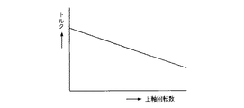
即ち、例えば、ミシン回転が高速になる程に糸が締まる場合は、図10の主軸(上軸)回転数−制動トルク特性図に示したように、ミシンの主軸である上軸の回転が高速になる程、前記ヒステリシスブレーキ11の制動トルクを下げる。
このような制御を行うことによって、ミシンの回転数の変化がなされても、同じ縫目が得られる。
【0034】
<第3の実施の形態例>
この第3の実施の形態例は、ミシンの主軸の1回転のなかで前記ヒステリシスブレーキ11の制動トルクの変化がなされるように構成したものである。
即ち、例えば、図11の主軸(上軸)回転角−制動トルク特性図に示したように、ミシンの上軸の1回転において、糸締め範囲以外は前記ヒステリシスブレーキ11の制動トルクを下げる。
このような制御を行うことによって、柔らかい縫目が得られる。
【0035】
<第4の実施の形態例>
この第4の実施の形態例は、ミシンに備えられる図示しない布押え上げ装置の動作と連動して前記ヒステリシスブレーキ11の制動トルクの変化がなされるように構成したものである。
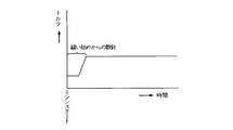
即ち、例えば、図12の時間−押え上げ信号/制動トルク特性図に示したように、ミシンに備えられる図示しない布押えが上がっている状態では、前記ヒステリシスブレーキ11の制動トルクを下げる。
このような制御を行うことによって、図示しない布が引き出し易くなる。
【0036】
<第5の実施の形態例>
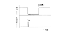
この第5の実施の形態例は、ミシンに備えられる図示しない糸切り装置による糸切り時に前記ヒステリシスブレーキ11の制動トルクの変化がなされるように構成したものである。
即ち、例えば、図13の時間−糸切り信号/制動トルク特性図に示したように、糸切り信号がONすると、糸切り終了まで前記ヒステリシスブレーキ11の制動トルクを下げる。また、糸切り条件によっては、糸切り開始前後及び終了時、前後のヒステリシスブレーキ11の制動トルクコントロールのタイミングを任意に変えて適切な糸張力を得られるようにすることも考えられる。
このような制御を行うことによって、適切な糸切りが可能であると同時に、糸切りの際はその糸切り終了まで糸張力付与装置側から上糸が繰り出せるため、切断した糸が針から抜けず、糸切り時の上糸抜けがない。
また、糸切り後の上糸長さは、ミシンに備えられる図示しないプリテンション装置により調節されるが、糸張力付与装置(ヒステリシスブレーキ11)の制動トルクの大きさによっても調節できるため、安定した上糸残り量になる。
【0037】
<第6の実施の形態例>
この第6の実施の形態例は、バック縫いの際は前記ヒステリシスブレーキ11の制動トルクの変化がなされるように構成したものである。
即ち、例えば、バック縫いの際には一般的にヒッチステッチになることから糸が締まらない場合、図14の時間−バック信号/制動トルク特性図に示したように、バック信号がONの時に前記ヒステリシスブレーキ11の制動トルクを上げる。
このような制御を行うことによって、バック縫いでも同じ縫目が得られる。
【0038】
<第7の実施の形態例>
この第7の実施の形態例は、縫製開始の際に前記ヒステリシスブレーキ11の制動トルクの変化がなされるように構成したものである。
即ち、例えば、図15の縫製開始からの時間−制動トルク特性図に示したように、縫い始めの際には、ミシンスタートから数針分だけ前記ヒステリシスブレーキ11の制動トルクを下げる。
このような制御を行うことによって、縫い始めの際に糸張力付与装置(ヒステリシスブレーキ11)側から上糸を充分に繰り出させるため、上糸端は引き込まれず、縫い始めの目飛びがない。
また、縫い始めは糸がほつれ易いことから、例えば、縫い始めに前記ヒステリシスブレーキ11の制動トルクを上げることで、糸締めを行って、縫い始めから糸をほつれ難くすることもできる。
【0039】
<第8の実施の形態例>
この第8の実施の形態例は、布の段部検知により前記ヒステリシスブレーキ11の制動トルクの変化がなされるように構成したものである。
即ち、例えば、布の厚くなった段部への縫製により糸が締まらない場合、図16の時間−段部検知信号/制動トルク特性図に示したように、図示しない布段部検知装置が段部を検知すると、前記ヒステリシスブレーキ11の制動トルクを上げる。
このような制御を行うことによって、布が厚くなった段部への縫製でも糸の締りが安定している縫目が得られる。
【0040】
<第9の実施の形態例>
この第9の実施の形態例は、2本針本縫いミシンにおいて、左右独立した糸張力付与装置(ヒステリシスブレーキ11)を使用し、それぞれの制動トルクを個別に可変制御するように構成したものである。
即ち、例えば、図17の2本針ミシンの要部斜視図に示したように、ミシン頭部に、右針8Rへの上糸5Rに対する糸車1R及びヒステリシスブレーキ11Rと、左針8Lへの上糸5Lに対する糸車1L及びヒステリシスブレーキ11Lとを備えて、例えば、左針8L側での糸締りに対し右針8R側での糸締りが締まる場合には、右針8R側のヒステリシスブレーキ11Rの制動トルクを下げる。
このような制御を行うことによって、左右共に同じ縫目が得られる。
【0041】
<第10の実施の形態例>
この第10の実施の形態例は、2本針本縫いミシンにおいて、左右独立した糸張力付与装置(ヒステリシスブレーキ11)を使用し(前記図17参照)、片針停止時にはその停止した方のヒステリシスブレーキ11の制動トルクの変化がなされるように構成したものである。
即ち、例えば、図18の2本針ミシンによる片針停止を伴う縫製例に示したように、右曲がりの角縫い縫製の場合には、角部の数針は左針のみによる縫製になり、右針は縫製しないが、布は送られるため、その上糸が繰り出されてしまう。
そこで、左針のみの縫製時は、右針側の糸張力付与装置(図17のヒステリシスブレーキ11R参照)の制動トルクを上げる。
このような制御を行うことによって、右針側の上糸を繰り出させなくして、再度縫製が始まっても左右共に同じ縫目が得られる。
【0042】
<第11の実施の形態例>
この第11の実施の形態例は、千鳥縫いミシンにおいて、右針落ちと左針落ちで前記ヒステリシスブレーキ11の制動トルクの変化がなされるように構成したものである。
即ち、例えば、図19の千鳥縫いミシンによる千鳥縫い例に示したように、右針落ちで糸が締まり、左針落ちで糸が締まらない場合は、右針落ちの時に前記ヒステリシスブレーキ11の制動トルクを下げ、左針落ちの時に制動トルクを上げる。
このような制御を行うことによって、左右の針落ちで同じ縫目が得られる。
【0043】
<第12の実施の形態例>
この第12の実施の形態例は、穴かがりミシンにおいて、平行部の縫製と閂止め部の縫製とで前記ヒステリシスブレーキ11の制動トルクの変化がなされるように構成したものである。
即ち、例えば、図30に示すように、従来の穴かがりミシンは、そのミシン頭部に3個の糸張力付与装置91,92,92を備え、平行部の縫製を1個の糸張力付与装置91で調整し、閂止め部の縫製を2個の糸張力付与装置92,92で調整するよう切り替えていたが、この実施の形態例では、例えば、図20の穴かがりミシンの要部斜視図に示したように、1個の糸張力付与装置(ヒステリシスブレーキ11)31を備えて、その制動トルクを平行部の縫製と閂止め部の縫製とで変化させる。
このような制御を行うことによって、従来と同様に備えられるプリテンション装置32と併せて2個の糸張力付与装置により、例えば、図21に示したように、閂止め部33,33と平行部34,34の縫目調整が得られる。
【0044】
<第13の実施の形態例>
この第13の実施の形態例は、家庭用ミシン、閂止め縫いミシンまたは自動機ミシンにおいて、パターン縫いにおける前記ヒステリシスブレーキ11の制動トルクの変化がなされるように構成したものである。
即ち、家庭用ミシン、閂止め縫いミシンまたは自動機ミシンによるパターン縫いは、周知の如くカム式とX−Y駆動式とがあり、各々の運針に対し前記ヒステリシスブレーキ11の制動トルクを設定する。例えば、直線縫いの時に糸をしっかり締めて、刺繍部では糸を柔らかく締めたい場合には、前記ヒステリシスブレーキ11の制動トルクを、直線縫いの時に比べ刺繍部で下げる。
このような制御を行うことによって、縫製する部分により縫目を変えられる。
また、例えば、図22のパターン縫いによるパーフェクトステッチとヒッチステッチが混在した縫製例に示すように、前記ヒステリシスブレーキ11の制動トルクを適切に変える制御を行うことで、同じ糸締りの縫目が得られるようになる。
【0045】
<第14の実施の形態例>
この第14の実施の形態例は、ロックミシンにおいて、前記ヒステリシスブレーキ11の制動トルクの設定により縫目の変化がなされるように構成したものである。
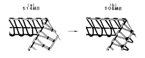
即ち、例えば、図23の縫目形式の変化例(a)から(b)に示すように、図23(a)に示した縫目形式514の縫目で左針側の前記ヒステリシスブレーキ11の制動トルクを上げて縫糸となる上糸張力を下げ、縫糸となる下ルーパー糸張力を上げると、図23(b)に示した通り、縫目形式506の縫目に変わる。
また、図24の縫目形式の変化例(a)から(b)に示すように、図24(a)に示した縫目形式504の縫目で前記ヒステリシスブレーキ11の制動トルクを上げて縫糸となる上糸張力を下げ、縫糸となる下ルーパー糸張力を上げると、図24(b)に示した通り、縫目形式505の縫目に変わる。
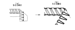
同様に、図25の縫目形式の変化例(a)から(b)に示すように、図25(a)に示した縫目形式502の縫目で前記ヒステリシスブレーキ11の制動トルクを上げて縫糸となる上糸張力を下げ、縫い糸となるルーパー糸張力を上げると、図25(b)に示した通り、縫目形式503の縫目に変わる。
【0046】
<第15の実施の形態例>
この第15の実施の形態例は、ロックミシンにおいて、空環巻き込み時に前記ヒステリシスブレーキ11の制動トルクの設定により縫目の変化がなされるように構成したものである。
即ち、例えば、図31に示すように、従来のロックミシンは、上下2段で計4〜8個の糸張力付与装置93(図示例では上下段とも3個ずつの糸張力付与装置94,95)を備え、空環巻き込み時にソフトチェーンにするために、マグネットで上段の糸張力付与装置94と下段の糸張力付与装置95に切り替えていたが、この実施の形態例では、例えば、図26のロックミシンの斜視図に示したように、1段で3個の糸張力付与装置(ヒステリシスブレーキ11)41を備えて、その制動トルクを適切に変化させる。
このような制御を行うことによって、1段の糸張力付与装置41によりソフトチェーンが得られる。
【0047】
<第16の実施の形態例>
この第16の実施の形態例は、縫製条件によって前記ヒステリシスブレーキ11の制動トルクを設定がなされるように構成したものである。
即ち、例えば、縫製条件とは、前記図8の制御装置の構成及びその入出力信号に示したように、布や糸の材質、糸の種類や番手等であり、例えば、ブラウス等の薄物の場合には、パッカリング等の問題が発生するため、前記ヒステリシスブレーキ11の制動トルクを低トルク域に設定し、逆に、ジーンズ等の厚物の場合には、前記ヒステリシスブレーキ11の制動トルクを高トルク域に設定することで、しっかりと糸が締められるなど、簡単に制動トルクの設定の切り替えができ
る。
【0048】
<第17の実施の形態例>
この第17の実施の形態例は、ミシンの適所に、前記ヒステリシスブレーキ11の制動トルクによる糸張力表示部を設けたものである。
即ち、例えば、図27の縫製装置の一例に示すように、ミシンのテーブル上に設置される制御盤50に、前記ヒステリシスブレーキ11の制動トルクが表示される制動トルク表示部51を設ける。
このように、制動トルク表示部51を設けると、そのトルクは縫糸張力であり、つまり、縫糸張力が表示されるので、その糸張力の表示に基づいて同じ糸張力の再現が容易にできる。
なお、糸張力表示部(制動トルク表示部)51は、制御盤50に限らず、ミシン頭部やテーブル下などに配置してもよい。
【0049】
<第18の実施の形態例>
この第18の実施の形態例は、ミシンの適所に、前記ヒステリシスブレーキ11の制動トルクによる糸張力設定部を設けたものである。
即ち、例えば、前記図27の縫製装置の一例に示したように、ミシンのテーブル上に設置される制御盤50に、前記ヒステリシスブレーキ11の制動トルクの設定が行える設定ボリュームや設定値入力装置による糸張力設定部52を設ける。
このように、糸張力設定部52を設けると、その設定ボリュームや設定値入力装置を操作して、容易に適切な制動トルクに変えられる。
なお、糸張力設定部(設定ボリュームや設定値入力装置)52は、制御盤50に限らず、ミシン頭部やテーブル下などに配置してもよい。
【0050】
<第19の実施の形態例>
この第19の実施の形態例は、ミシンアームに前記ヒステリシスブレーキ11を内蔵したものである。
即ち、例えば、図32に示したような従来の糸調子96(97は糸車、98は糸調子本体)の代わりに、図28のミシンの要部の一例に示すように、糸車1を備えた前記ヒステリシスブレーキ11と同様の構成による糸張力付与装置61をミシンアームに内蔵している。
このように、従来の糸調子本体98の代わりに、前記ヒステリシスブレーキ11と同様の構成による糸張力付与装置61をミシンアームに内蔵して備えられる。
【0051】
<第20の実施の形態例>
この第20の実施の形態例は、ミシンアームに対して前記ヒステリシスブレーキ11をオプション化したものである。
即ち、例えば、前記図32に示したような通常備えられる従来の前記糸調子96の代わりに交換できるよう、前記図28のミシンの要部の一例に示したように、糸車1を備えた前記ヒステリシスブレーキ11と同様の構成による糸張力付与装置61をオプションとしてミシンアームに内蔵して備えら得るようにしている。
このように、必要に応じて、通常備えられる前記糸調子96の代わりに交換して前記ヒステリシスブレーキ11と同様の構成による糸張力付与装置61をミシンに備えられる。
【0052】
<第21の実施の形態例>
この第21の実施の形態例は、前述した第1の実施の形態例における糸張力付与装置の変形例に関するもので、その概略構成を示した図29において、71は電磁ブレーキ(ヒステリシスブレーキ)、72は出力軸、73は回転体(ローラ)、74は押し付けローラ、75は縫糸、76はローラホルダ、77は押し付けばねである。
即ち、図29に示すように、電磁ブレーキであるヒステリシスブレーキ71は、その出力軸72上に回転体であるローラ73を固着して備えており、このローラ73と押し付けローラ74との間に縫糸75が挟み込まれている。
つまり、押し付けローラ74はローラホルダ76に支持されており、このローラホルダ76に押し付けばね77を接続することによって、押し付けローラ74が縫糸75を挟んでローラ74に押し付けられている。
【0053】
このように、ミシンの糸張力付与装置において、高張力の場合におけるスリップ防止のために縫糸75を両ローラ73,74で挟むようにしてもよい。
なお、この第21の実施の形態例におけるヒステリシスブレーキ71によっても、前述した第1の実施の形態例におけるヒステリシスブレーキ11と同様の機能が得られることは勿論である。
また、この第21の実施の形態例におけるヒステリシスブレーキ71も、前述した第1の実施の形態例におけるヒステリシスブレーキ11と同じく、前述した第2の実施の形態例から第20の実施の形態例にも同様に適用可能である。
【0054】
なお、以上の実施の各形態例においては、ミシンの糸張力制御装置に用いる電磁ブレーキとしてヒステリシスブレーキとしたが、これに限定されるものではなく、同じ電磁ブレーキであるパウダブレーキを用いても同等の効果が得られる。
さらに、その他、ミシンの具体的な制御方法や具体的な細部構造等についても適宜に変更可能であることは勿論である。
【0055】
ここで、パウダブレーキについて簡単に説明する。
パウダブレーキは、図示しないが公知のように、固定軸と回転軸を同心円筒上にパウダギャップを隔てて配置し、そのパウダギャップに透磁率の高いパウダ(磁性鉄粉)を入れて、そのパウダに磁束を流すようステータ外周に励磁コイルを配置したものである。
このような構成のパウダブレーキは、無励磁で回転軸が回転していれば、パウダは遠心力により回転軸動作面に押し付けられ、回転軸と固定軸とは何ら連結状態にないが、コイルを励磁すると、発生した磁束に沿ってパウダが鎖状に連結し、そのパウダ間の連結力及びパウダと動作面との摩擦力により回転軸に制動力が働くものである。
以上のようなパウダブレーキは、以下に列挙する特長を有する。
(1)広範囲の制御が容易である。即ち、励磁電流と制動トルクの関係がほぼ比例的であり、制動トルクを広範囲にわたって簡単に制御できる。
(2)連続スリップ運転が可能である。即ち、パウダを使用するため、動作面は連続スリップが可能であり、また、スリップ回転速度に関係なく常に安定したスリップトルクが得られる。
(3)安定したトルクが得られる。即ち、動作面形状、ラビリンス形状等により常にパウダは正常に働くため、電流の0N/0FFを繰り返しても極めて安定したトルクが再現できる。
(4)鳴き音がない。即ち、摩擦板方式に見られる動作面のスティックスリップがなく、また、停止音も発生しないため、静粛運転できる。
(5)熱容量が大きい。即ち、耐熱性に優れたパウダを使用し、理想的な冷却方法の採用により、過酷な連続運転でも安心して使用できる。
(6)スムーズな停止・駆動が可能である。即ち、静摩擦係数と動摩擦係数はほぼ等しいため、完全停止時のショックもなく、負荷に応じた加減速度が得られる。
【0056】
以上の実施の形態例では、ヒステリシスブレーキに代表される電磁ブレーキを用いた糸張力制御装置について説明したが、以降の実施の形態例からは、ボイスコイルモータに代表されるリニアモータを含む低イナーシャモータを用いた糸張力制御装置について説明する。
【0057】
<第22の実施の形態例>
この第22の実施の形態例は、請求項1、2記載の発明の具体例に相当するものである。
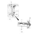
即ち、図33は請求項1、2記載の発明の具体例に相当する第22の実施の形態例を示すもので、軸線方向に動作する動作軸に糸調子皿を設けた低イナーシャモータとしてのボイスコイルモータによる糸張力付与装置の要部を示した縦断側面図である。
この図33において、100はミシンアームブロック、101は糸調子皿、102は外皿(固定皿)、103は内皿(可動皿)、104は中空軸、105は動作軸、106は当接片、107は軸受ケース、108はコイルバネ、109は糸掛け棒、111は低イナーシャモータ(ボイスコイルモータ)、112は磁気回路、113は円筒型ヨーク、114は永久磁石(外極)、115は鉄心(中央極)、116は可動コイル、117は補償銅管、118はコイル、119はコイルヘッドである。
【0058】
図33に示すように、ミシンアームブロック100に備えられる糸調子皿101は、対をなす外皿102及び内皿103からなるもので、この実施の形態例では、中空軸104上に、その先端部のフランジ側に外皿による固定皿102を組み付けて、この固定皿102と対向する内皿である可動皿103をスライド自在に組み付けている。
そして、中空軸104の内部には、動作軸105がスライド自在に挿入されていて、この動作軸105の先端部による押される当接片106が設けられており、この当接片106は、可動皿103と一体のものである。
なお、この実施の形態例とは逆に、内皿103を固定皿として、外皿102を可動皿としてもよく、その場合には、当接片106を可動皿となる外皿102と一体に設けて、その当接片106に動作軸105の先端部を係合等により接続することで、動作軸105により当接片106が引かれるようにしておく。
以上の糸調子皿101の中空軸104は、軸受ケース107に回転自在に軸受されており、軸受ケース107はミシンアームブロック100の組み込み穴に填め込んで固定されている。
また、軸受ケース107内にコイルバネ108が介装されており、このコイルバネ108の先端部には、糸調子皿101の外周に臨む糸掛け棒109が一体に形成されている。
【0059】
そして、糸調子皿101の中空軸104に内部に挿入される動作軸105は、低イナーシャモータであるリニア直流モータとしてのボイスコイルモータ111により駆動される。
このボイスコイルモータ111は、磁気回路112を構成する円筒型ヨーク113、その端部内周に設けた永久磁石による外極114、前記円筒形ヨーク113の中心部に一体的に設けた鉄心による中央極115と、この中央極115と外極114との間に配設される円筒状の可動コイル116とからなるものである。
また、可動コイル116は、補償銅管117の外周にコイル118を設けたもので、その先端部のコイルヘッド119の中央部に前記動作軸105を一体的に備えている。
以上のボイスコイルモータ111は、磁気回路112の中央極(鉄心)115の外周におかれた外極(永久磁石)114から可動コイル116に磁界が作用しており、この磁界中にある可動コイル(コイル118)116に制御電流供給回路(CC)110(図36参照)から供給される制御電流によって、可動コイル116に推力(または吸引力)が生じ、コイルヘッド119に備えた動作軸105が中空軸104内を前進(または後退)する。
【0060】
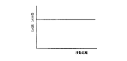
以上のボイスコイルモータ111の移動距離−吸引力(推力)特性を図34に示しており、同じく電流−吸引力(推力)特性を図35に示している。
即ち、ボイスコイルモータ111は、インダクタンスが小さくて応答が早いという特性、移動体が可動コイル116だけなので、慣性が小さくて応答が早いという特性を具備する他、図34に示すように、可動コイル116の吸引力(推力)が距離に関係なく一定で、さらに、図35に示すように、電流に比例した線形の吸引力(推力)が取り出せるといった特性を具備するものである。
このような特性を具備するボイスコイルモータ111なので、その可動コイル116と一体の動作軸105による中空軸104内の前進(または後退)動作によって、当接片106を介して可動皿103が軸線方向に移動して、固定皿102との間の隙間を変えて、糸調子皿101を通す糸に対する把持力を変えることができる。
【0061】
図36は以上のようなボイスコイルモータ111を用いた糸張力付与装置をミシンに装着した状態の糸系統図であり、図示のように、縫糸である上糸5の糸巻6と天秤9との間の糸経路に、ボイスコイルモータ111による動作軸105上に設けた糸調子皿101を配置している。
具体的には、図示の通り、上糸5が糸巻6から繰り出されて糸取りバネ7に至る経路において、糸調子皿101による上糸5の繰り出し量をボイスコイルモータ111で規制するものである。
また、ボイスコイルモータ111の制御電流は制御電流供給回路(CC)110により供給される。
【0062】
次に、図38は以上の糸張力付与装置を制御する制御装置の構成及びその入出力信号を示すもので、この制御装置21は、外部から各種信号(糸切り信号、ミシン回転数、ミシン位相信号、押え高さ信号、押え上げ信号、針上下左右位置信号、バック信号、片針停止信号、布有無信号等)や設定条件(縫製条件としての針、糸種類、糸番手、糸メーカー、布厚、布種類、張力等)を入力する。
そして、内部のCPUによりROMやRAMに設定されているデータと比較演算し、最適な縫目が得られるようにボイスコイルモータ111に流す電流を制御すると共に、サーボモータ22には縫目が適した回転数になるよう制御信号出力し、また、オペレータにはメッセージを表示23する。
なお、縫製で得られた制御信号データは、ROMやRAMにデータベースとして貯えられ、カード等のリムーバブル記憶装置24で入れ替えができ、また、LANまたはコンピュータネットワークを用いてホストコンピュータ25(或いはサーバ)等にデータを貯えることもできる。
このような制御を行うことにより、次の縫製時に一番近いデータを導き出せるので、段取り替え時間が短縮される。
【0063】
図39は以上の制御装置21による処理の一例としてのフローチャートを示したものである。
即ち、縫製条件が入力されると、前記データベースからのデータに基づいて前記サーボモータ22に最大回転数の制御信号が出力されるが、データベースにデータがない場合は、先ず、ステップS1で糸張力を入力する。
その後、回転数の検出と演算処理(ステップS2)、位相の検出と演算処理(ステップS3)、布押え高さの検出と演算処理(ステップS4)、バック縫いの検出と演算処理(ステップS5)、針左右位置の検出と演算処理(ステップS6)、布押え上げ位置の検出と演算処理(ステップS7)、糸切りの検出と演算処理(ステップS8)、布有無の検出と演算処理(ステップS9)、片針停止の検出と演算処理(ステップS10)等の各種検出・演算処理を行ってから、前記制御電流供給回路110に前記ボイスコイルモータ111の前記可動コイル116へ供給する制御電流を出力する。
以上のような処理は、糸張力の入力後は縫製中繰り返し行う。
【0064】
以上の実施の形態例に係るボイスコイルモータ111により把持力を制御する糸調子器(糸調子皿101)を用いたミシンの糸張力制御装置によれば、以下に列挙する作用効果が得られる。
(1)インダクタンスが小さく、応答が早い。
(2)移動体が可動コイル116だけなので、慣性が小さく、応答が早い。
【0065】
(3)可動コイル116の吸引力(推力)が距離に関係なく一定であり、電流に比例した吸引力(推力)、即ち、圧力が得られる。
従って、次の利点が得られる。
[1]糸の太さが変化するようなスパン糸や毛糸の場合でも張力が変化しない。
[2]太さの違う糸に交換しても、張力が大きく変化しない。
[3]リンク等の駆動力伝達機構が介在する場合でも、組付位置のずれがあっても張力にバラツキが発生しない。
【0066】
(4)電流値と張力の直進性が良い。即ち、流す電流値によって張力は一義的に決まってしまう。
(5)電源投入時に原点復帰(イニシャライズ)する必要がない。
(6)ストロークが大きく取れ、リンク等の駆動力伝達機構で吸引力(推力)を増やすのに適している。
【0067】
なお、以上の如く列挙した利点は、ボイスコイルモータ111の吸引力(推力)による圧力をトルクに置き換えた、後述するコアレスモータによっても同様に得られる。
【0068】
<第23の実施の形態例>
図37は、図33の糸張力付与装置に圧力センサを設けた状態を示した縦断側面図である。
図37において、121は圧力センサ(圧力検出手段)であり、この圧力センサ121を、糸調子皿101の固定皿102と中空軸104の端部フランジとの間に設けている。
このような圧力センサ121によって、ボイスコイルモータ111による動作軸105の軸方向動作力により可動皿103から固定皿102に作用する圧力を検出でき、その検出した圧力をフィードバックして糸調子皿101による糸把持力を制御するように構成する。
これにより、ボイスコイルモータ111により糸調子皿101に作用する圧力を監視しながら糸張力を適切に制御できるものとなる。
【0069】
<第24の実施の形態例>
この第24の実施の形態例は、図示しないが、糸張力を検出する糸張力センサ(糸張力検出手段)を設けている。
このような糸張力センサによって、ボイスコイルモータ111により糸調子皿101で糸に付与される張力を検出でき、その検出した糸張力をフィードバックして糸調子皿101による糸把持力を制御するように構成する。
これにより、ボイスコイルモータ111による糸調子皿101の把持による糸張力を監視しながら糸張力を適切に制御できるものとなる。
【0070】
<第25の実施の形態例>
この第25の実施の形態例は、ミシンの主軸の回転数の変化に応じて糸張力付与装置としての前記ボイスコイルモータ111による糸調子皿101の糸把持力の変化がなされるように構成したものである。
即ち、図40は第25の実施の形態例を示すもので、主軸(上軸)回転数−把持力(張力)特性図である。
例えば、ミシン回転が高速になる程に糸が締まる場合は、図40に示したように、ミシンの主軸である上軸の回転が高速になる程、前記ボイスコイルモータ111による糸調子皿101の糸把持力を下げるものとする。
このような制御を行うことによって、ミシンの回転数の変化がなされても、同じ縫目が得られる。
【0071】
なお、ミシンの主軸の1回転のなかで前記ボイスコイルモータ111による糸調子皿101の糸把持力の変化がなされるようにしてもよい。
即ち、図41は糸締め範囲を併せて示した主軸(上軸)回転数−把持力(張力)特性図である。
例えば、図41に示したように、ミシンの上軸の1回転において、糸締め範囲以外は前記ボイスコイルモータ111による糸調子皿101の糸把持力を下げるものとする。
このような制御を行うと、柔らかい縫目が得られる。
【0072】
<第26の実施の形態例>
この第26の実施の形態例は、ミシンに備えられる図示しない布押え上げ装置の動作と連動して前記ボイスコイルモータ111による糸調子皿101の糸把持力の変化がなされるように構成したものである。
即ち、図42は第26の実施の形態例を示すもので、時間−押さえ上げ信号/把持力(張力)特性図である。
例えば、図42に示したように、ミシンに備えられる図示しない布押えが上がっている状態では、前記ボイスコイルモータ111による糸調子皿101の糸把持力を下げるものとする。
このような制御を行うことによって、図示しない布が引き出し易くなる。
【0073】
<第27の実施の形態例>
この第27の実施の形態例は、ミシンに備えられる図示しない糸切り装置による糸切り時に前記ボイスコイルモータ111による糸調子皿101の糸把持力の変化がなされるように構成したものである。
即ち、図43は第27の実施の形態例を示すもので、時間−糸切り信号/把持力(張力)特性図である。
例えば、図43に示したように、糸切り信号がONすると、糸切り終了まで前記ボイスコイルモータ111による糸調子皿101の糸把持力を下げるものとする。
なお、糸切り条件によっては、糸切り開始前後及び終了時、前後のボイスコイルモータ111による糸調子皿101の糸把持タイミングを任意に変えて適切な糸張力を得られるようにすることも考えられる。
このような制御を行うことによって、適切な糸切りが可能であると同時に、糸切りの際はその糸切り終了まで糸張力付与装置側から上糸が繰り出せるため、切断した糸が針から抜けず、糸切り時の上糸抜けがない。
また、糸切り後の上糸長さは、ミシンに備えられる図示しないプリテンション装置により調節されるが、糸張力付与装置(ボイスコイルモータ111の駆動による糸調子皿101)の糸把持力の大きさによっても調節できるため、安定した上糸残り量になる。
【0074】
<第28の実施の形態例>
この第28の実施の形態例は、バック縫いの際は前記ボイスコイルモータ111による糸調子皿101の糸把持力の変化がなされるように構成したものである。
即ち、図44は第28の実施の形態例を示すもので、時間−バック信号/把持力(張力)特性図である。
例えば、バック縫いの際には一般的にヒッチステッチになることから糸が締まらない場合、図44に示したように、バック信号がONの時に前記ボイスコイルモータ111による糸調子皿101の糸把持力を上げるものとする。
このような制御を行うことによって、バック縫いでも同じ縫目が得られる。
【0075】
<第29の実施の形態例>
この第29の実施の形態例は、縫製開始の際に前記ボイスコイルモータ111による糸調子皿101の糸把持力の変化がなされるように構成したものである。
即ち、図45は第29の実施の形態例を示すもので、時間−把持力(張力)特性図である。
例えば、図45に示したように、縫い始めの際には、ミシンスタートから数針分だけ前記ボイスコイルモータ111による糸調子皿101の糸把持力を下げるものとする。
このような制御を行うことによって、縫い始めの際に糸張力付与装置(ボイスコイルモータ111の駆動による糸調子皿101)側から上糸を充分に繰り出させるため、上糸端は引き込まれず、縫い始めの目飛びがない。
また、縫い始めは糸がほつれ易いことから、例えば、縫い始めに前記ボイスコイルモータ111による糸調子皿101の糸把持力を上げることで、糸締めを行って、縫い始めから糸をほつれ難くすることもできる。
【0076】
<第30の実施の形態例>
この第30の実施の形態例は、布の段部検知により前記ボイスコイルモータ111による糸調子皿101の糸把持力の変化がなされるように構成したものである。
即ち、図46は第30の実施の形態例を示すもので、時間−段部検知信号/把持力(張力)特性図である。
例えば、布の厚くなった段部への縫製により糸が締まらない場合、図46に示したように、図示しない布段部検知装置が段部を検知すると、前記ボイスコイルモータ111による糸調子皿101の糸把持力を上げるものとする。
このような制御を行うことによって、布が厚くなった段部への縫製でも糸の締りが安定している縫目が得られる。
【0077】
<第31の実施の形態例>
この第31の実施の形態例は、2本針本縫いミシンにおいて、左右独立した糸張力付与装置(ボイスコイルモータ111の駆動による糸調子皿101)を使用し、それぞれの糸把持力を個別に可変制御するように構成したものである。
即ち、図47は第31の実施の形態例を示すもので、2本針ミシンの要部斜視図である。
例えば、図47に示したように、ミシン頭部に、右針8Rへの上糸5Rに対する糸調子皿101R及びボイスコイルモータ111Rと、左針8Lへの上糸5Lに対する糸調子皿101L及びボイスコイルモータ111Lとを備えて、例えば、左針8L側での糸締りに対し右針8R側での糸締りが締まる場合には、右針8R側のボイスコイルモータ111Rによる糸調子皿101Rの把持力を下げるものとする。
このような制御を行うことによって、左右共に同じ縫目が得られる。
【0078】
<第32の実施の形態例>
図48は第32の実施の形態例を示すもので、回転数−把持力(張力)特性図である。
この実施の形態例では、前記糸張力付与装置(ボイスコイルモータ111の駆動による糸調子皿101)よりも糸供給側(糸巻側)に、プリテンション用の図示しない第1糸調子器を設けておいて、その第1糸調子器により付与される糸張力を超える変化分だけ、前記ボイスコイルモータ111による糸調子皿101の糸把持力により糸張力を制御するものとする。
こうすれば、図48に示したように、糸張力に変化を必要としない領域において、従来と同様の第1糸調子器で持たせながら、その第1糸調子器による糸張力を超えて糸張力の変化を必要とする領域においては、ボイスコイルモータ(VCM)111による糸調子皿101の糸把持力により持たせることによって、高張力にも対応できるものとなる。
【0079】
<第33の実施の形態例>
この第33の実施の形態例は、2本針本縫いミシンにおいて、左右独立した糸張力付与装置(ボイスコイルモータ111の駆動による糸調子皿101)を使用し(前記図47参照)、片針停止時にはその停止した方のボイスコイルモータ111による糸調子皿101の糸把持力の変化がなされるように構成したものである。
即ち、図49は第33の実施の形態例を示すもので、2本針ミシンによる片針停止を伴う縫製例を示した平面図である。
例えば、図49に示したように、右曲がりの角縫い縫製の場合には、角部の数針は左針のみによる縫製になり、右針は縫製しないが、布は送られるため、その上糸が繰り出されてしまう。
そこで、左針のみの縫製時は、右針側の糸張力付与装置(図47のボイスコイルモータ111Rによる糸調子皿101R参照)の糸把持力を上げるものとする。
このような制御を行うことによって、右針側の上糸を繰り出させなくして、再度縫製が始まっても左右共に同じ縫目が得られる。
【0080】
<第34の実施の形態例>
この第34の実施の形態例は、千鳥縫いミシンにおいて、右針落ちと左針落ちで前記ボイスコイルモータ111による糸調子皿101の糸把持力の変化がなされるように構成したものである。
即ち、図50は第34の実施の形態例を示すもので、千鳥縫いミシンによる千鳥縫いを例示した平面図である。
例えば、図50の千鳥縫い例に示したように、右針落ちで糸が締まり、左針落ちで糸が締まらない場合は、右針落ちの時に前記ボイスコイルモータ111による糸調子皿101の糸把持力を下げ、左針落ちの時に把持力を上げるものとする。
このような制御を行うことによって、左右の針落ちで同じ縫目が得られる。
【0081】
<第35の実施の形態例>
この第35の実施の形態例は、穴かがりミシンにおいて、平行部の縫製と閂止め部の縫製とで前記ボイスコイルモータ111による糸調子皿101の糸把持力の変化がなされるように構成したものである。
即ち、図51は第35の実施の形態例を示すもので、穴かがりミシンを示した要部斜視図であり、図52その穴かがりミシンによる縫製例を示した平面図である。
この実施の形態例では、例えば、図51に示したように、1個の糸張力付与装置(ボイスコイルモータ111の駆動による糸調子皿101)131を備えて、その糸把持力を平行部の縫製と閂止め部の縫製とで変化させるものとする。
このような制御を行うことによって、従来と同様に備えられるプリテンション装置32と併せて2個の糸張力付与装置により、例えば、図52に示したように、閂止め部33,33と平行部34,34の縫目調整が得られる。
【0082】
<第36の実施の形態例>
この第36の実施の形態例は、家庭用ミシン、閂止め縫いミシンまたは自動機ミシンにおいて、パターン縫いにおける前記ボイスコイルモータ111による糸調子皿101の糸把持力の変化がなされるように構成したものである。
即ち、図53は第36の実施の形態例を示すもので、パターン縫いによるパーフェクトステッチとヒッチステッチが混在する縫製例を示した平面図である。
ところで、家庭用ミシン、閂止め縫いミシンまたは自動機ミシンによるパターン縫いは、周知の如くカム式とX−Y駆動式とがあり、各々の運針に対し前記ボイスコイルモータ111による糸調子皿101の糸把持力を設定する。例えば、直線縫いの時に糸をしっかり締めて、刺繍部では糸を柔らかく締めたい場合には、前記ボイスコイルモータ111による糸調子皿101の糸把持力を、直線縫いの時に比べ刺繍部で下げるものとする。
このような制御を行うことによって、縫製する部分により縫目を変えられる。
また、例えば、図53のパターン縫いによるパーフェクトステッチとヒッチステッチが混在した縫製例に示すように、前記ボイスコイルモータ111による糸調子皿101の糸把持力を適切に変える制御を行うことで、同じ糸締りの縫目が得られるようになる。
【0083】
<第37の実施の形態例>
この第37の実施の形態例は、ロックミシンにおいて、前記ボイスコイルモータ111による糸調子皿101の糸把持力の設定により縫目の変化がなされるように構成したものである。
即ち、図54から図56は第37の実施の形態例を示すもので、図54(a)は縫い目形式514の縫い目を例示した斜視図、図54(b)は縫い目形式506の縫い目を例示した斜視図であり、図55(a)は縫い目形式504の縫い目を例示した斜視図、図55(b)は縫い目形式505の縫い目を例示した斜視図、図56(a)は縫い目形式504の縫い目を例示した斜視図、図56(b)は縫い目形式503の縫い目を例示した斜視図である。
例えば、図54の縫目形式の変化例(a)から(b)に示すように、図54(a)に示した縫目形式514の縫目で左針側の前記ボイスコイルモータ111による糸調子皿101の糸把持力を上げて縫糸となる上糸張力を下げ、縫糸となる下ルーパー糸張力を上げると、図54(b)に示した通り、縫目形式506の縫目に変わる。
また、図55の縫目形式の変化例(a)から(b)に示すように、図55(a)に示した縫目形式504の縫目で前記ボイスコイルモータ111による糸調子皿101の糸把持力を上げて縫糸となる上糸張力を下げ、縫糸となる下ルーパー糸張力を上げると、図55(b)に示した通り、縫目形式505の縫目に変わる。
同様に、図56の縫目形式の変化例(a)から(b)に示すように、図56(a)に示した縫目形式502の縫目で前記ボイスコイルモータ111による糸調子皿101の糸把持力を上げて縫糸となる上糸張力を下げ、縫い糸となるルーパー糸張力を上げると、図56(b)に示した通り、縫目形式503の縫目に変わる。
【0084】
<第38の実施の形態例>
この第38の実施の形態例は、ロックミシンにおいて、空環巻き込み時に前記ボイスコイルモータ111による糸調子皿101の糸把持力の設定により縫目の変化がなされるように構成したものである。
即ち、図57は第38の実施の形態例を示すもので、ロックミシンを示した要部斜視図である。
この実施の形態例では、例えば、図57に示したように、1段で3個の糸張力付与装置(ボイスコイルモータ111の駆動による糸調子皿101)141を備えて、その糸把持力を適切に変化させる。
このような制御を行うことによって、1段の糸張力付与装置141によりソフトチェーンが得られる。
【0085】
<第39の実施の形態例>
図58は第39の実施の形態例を示すもので、(a)は縫製装置の一例を示した要部斜視図、(b)は糸張力付与装置の半部破断側面図である。
例えば、図58に示すように、糸調子皿101を備えた前記ボイスコイルモータ111と同様の構成による糸張力付与装置151をミシンアームに内蔵している。
このように、従来の糸調子本体の代わりに、前記ボイスコイルモータ111の駆動による糸調子皿101と同様の構成による糸張力付与装置151をミシンアームに内蔵して備えられる。
また、このようなボイスコイルモータ111の駆動による糸調子皿101と同様の構成による糸張力付与装置151を、オプションとして備えたり、あるいは、通常備えられる糸調子と交換して備えることもできる。
【0086】
<第40の実施の形態例>
この第40の実施の形態例は、請求項1、2及び3記載の発明の具体例に相当するものである。
即ち、図59は請求項1、2及び3記載の発明の具体例に相当する第40の実施の形態例を示すもので、ボイスコイルモータから糸調子皿までの駆動機構を示した斜視図であり、図60はその糸張力付与装置をミシンに組み込んだ状態の一例を示した概略側面図である。
この実施の形態例では、図59に示すように、糸調子皿101の動作軸105とボイスコイルモータ111との間に駆動力伝達装置としてのリンク機構171を介設することで、糸張力付与装置160を構成している。
そして、ボイスコイルモータ111は、ブラケット161を用いて、図60に示すように、ミシンアームに対して糸調子皿101とは反対の裏面側に配置して固定している。
【0087】
リンク機構171は、図59に示したように、ボイスコイルモータ111の可動コイル116のコイルヘッド119の中央部に連結したロッド172と、このロッド172に継手173を介して一端部を連結し、他端側寄り部で支軸175を介してブラケット176に支持されたアーム174と、このアーム174の他端部に継手を介して連結したロッド177とから構成されている。
そして、このロッド177に前記動作軸105が連結されている。
また、ロッド177の先端部に設けたフランジ178と、糸調子皿101の中空軸104(あるいは軸受ケース107)の端面との間には、リンク機構171が有する摩擦力の分だけ動作軸105を戻すための圧縮コイルバネ179が介設されている。
以上のリンク機構171は、ミシンアームの内部に収容される。
【0088】
以上の通り、先ず、ボイスコイルモータ111は、ミシンアームに対して糸調子皿101とは反対の裏面側に配置されているので、縫製作業の邪魔にならないものとなっている。
そして、ボイスコイルモータ111からリンク機構171により動作軸105に駆動力が伝達され、そのリンク機構171によって、可動コイル116の推力(吸引力)が拡大されて動作軸105に入力されるため、ボイスコイルモータ111の駆動力に対して動作軸105のストロークを稼ぐことができ、従って、糸調子皿101による糸に対する高張力を得ることができるものとなる。
また、例えば、弱い糸張力の時にボイスコイルモータ111の制御電流を下げても、リンク機構171の摩擦力でボイスコイルモータ111にかかる圧力が開放されずに、糸張力がそのまま残ってしまうようなことが考えられるが、圧縮コイルバネ179の付勢力によって、ロッド177と共に動作軸105を迅速に戻せるため、ボイスコイルモータ111の制御電流を0にすると、糸張力も直ぐに0になるよう糸調子皿101を戻すことができる。
なお、駆動力伝達機構として、この実施の形態例では、回転方式によるリンク機構171を採用したが、他に、往復運動機構や、フレキシブルワイヤを用いたものでもよく、その構成は任意である。
【0089】
<第41の実施の形態例>
この第41の実施の形態例は、図示しないが、前述した第40の実施の形態例において、圧縮コイルバネ179に代えて、ボイスコイルモータ111に逆電流をかけることで、リンク機構171の摩擦力の分だけ可動コイル116を迅速に戻すように制御する。
従って、可動コイル116の戻りによりリンク機構171を介して動作軸105も迅速に戻るため、前述した第40の実施の形態例と同様に、ボイスコイルモータ111の制御電流を0にすると、糸張力も直ぐに0になるよう糸調子皿101を戻すことができる。
【0090】
<第42の実施の形態例>
図61は第42の実施の形態例を示すもので、図33と同様の糸張力付与装置に糸調子皿の隙間調節手段を設けた例を示した縦断側面図である。
この実施の形態例では、中空軸104の先端部外周に雄ねじ部181を形成して、この雄ねじ部181に、固定皿102と可動皿103からなる糸調子皿101の隙間調節手段としてのナット182をねじ込んでいる。つまり、このナット182の位置調節により固定皿102の位置が調節される。
先ず、前述した図33の糸張力付与装置と同様に、ボイスコイルモータ111により把持力を可変とされる糸調子皿101の一方のみを可動皿103としたことで、慣性を極力小さくして、高速での糸張力付加の追従性を上げることができる。
また、ナット182の位置調節応じて固定皿103の位置が変わり、初期設定のための糸調子皿101の隙間調節が適切に行えることから、例えば、隙間が大きくて糸張力0からの立ち上がりに時間がかかったり、隙間が狭くて糸を結んだコブ部分が引っかかるといった問題を解消することができる。
【0091】
<第43の実施の形態例>
図62は第43の実施の形態例を示すもので、主軸(上軸)回転角−送り歯高さ特性図である。
この実施の形態例では、図62に示すように、図示しない布押えの高さによる布厚の読込みを、図示しない送り歯の沈下時の位相状態で行い、その読込まれた布厚に対応して、前記ボイスコイルモータ111の駆動による糸調子皿101の糸把持力を変化させるものとする。
これにより、送り歯が沈んで布押えが布厚の分だけ浮いている状態で正確に布厚を検知して、布厚に応じた適切な糸張力の制御が行えるものとなる。
【0092】
<第44の実施の形態例>
この第44の実施の形態例は、図示しないが、布、糸、送りピッチ等の入力または選択に基づく縫製条件によって前記ボイスコイルモータ111の駆動による糸調子皿101の糸把持力の設定がなされるように構成するものである。
即ち、例えば、縫製条件とは、前記図38の制御装置の構成及びその入出力信号に示したように、布や糸の材質、糸の種類や番手等であり、例えば、ブラウス等の薄物の場合には、パッカリング等の問題が発生するため、前記ボイスコイルモータ111の駆動による糸調子皿101の糸把持力を低把持力域に設定し、逆に、ジーンズ等の厚物の場合には、前記ボイスコイルモータ111の駆動による糸調子皿101の糸把持力を高把持力域に設定することで、しっかりと糸が締められるなど、簡単に糸把持力の設定の切り替えができるものとなる。
【0093】
<第45の実施の形態例>
図63は第45の実施の形態例を示すもので、(a)は回転数−布枚数に対応する係数のデータカードの一例を示した正面図、(b)は回転数−主軸位相に対応する布枚数に応じたデータカードの一例を示した分解斜視図である。
この実施の形態例では、布厚を基準として、図63(a)に示すように、回転数及び布枚数に応じた係数を予め決めておいて、その布枚数に対応させて、図63(b)に示すように、回転数及び主軸位相の各データが決められたデータマップを、ミシンの制御装置のR0Mに入力しておくものとする。
これにより、データマップに従って布厚を基準とした、前記ボイスコイルモータ111の駆動による糸調子皿101の糸把持力に適切に制御することができる。
また、図示しない入力設定部における布、糸、送りピッチ等の入力または選択に基づく設定条件と、前記データマップとに従って、前記ボイスコイルモータ111の制御電流を決定するように構成してもよい。
このように、入力設定に基づく縫製条件とデータマップとによりボイスコイルモータ111の制御電流を決定しても、糸調子皿101による把持力を適切に制御することができる。
【0094】
<第46の実施の形態例>
図64は第46の実施の形態例を示すもので、糸張力付与装置の半部を破断して示した要部側面図である。
この実施の形態例では、図64に示すように、ミシンアームブロック100に内蔵したボイスコイルモータ111により駆動される糸調子皿101の手前側で、かつ、同軸上に位置する調節つまみ191をミシンアームブロック100に取り付けたブラケット192を介して設けて、この調節つまみ191の操作により、糸調子皿101の把持力による糸張力を微量調節可能とするよう制御装置を構成する。
これにより、通常備えられる糸調子皿の糸張力設定つまみと同じ位置に、ボイスコイルモータ111により駆動される糸調子皿101に対する糸張力微量調節可能な調節つまみ191があるので、違和感を与えることがないものとなる。
【0095】
<第47の実施の形態例>
図65は第47の実施の形態例を示すもので、主軸(上軸)回転角−上糸張力/上糸量/ボイスコイルモータ(VCM)電流特性図である。
この実施の形態例は、1台のミシンで、天秤締めと釜締めとを切り換えることにより、薄物から厚物までカバーできるようにしたものである。
ここで、一般に、薄物では天秤締め、厚物では釜締めが良いとされている。
このため、前記ボイスコイルモータ111の駆動による糸調子皿101の糸把持力を、図示しない天秤の引き上げ時と縫糸の釜越え時とでボイスコイルモータ(VCM)電流を切換可能としている。
これにより、1台のミシンで、天秤締めと釜締めとでボイスコイルモータ(VCM)電流を切り換えて、薄物から厚物までカバーできるものとなる。
【0096】
<第48の実施の形態例>
この第48の実施の形態例は、図示しないが、前記ボイスコイルモータ111の駆動による糸調子皿101の糸把持力を、例えば、膝スイッチ、手元スイッチ、押え上げスイッチ等の操作に基づくパターン切り換えに対応して変化させるものとする。
このように、ボイスコイルモータ111の駆動による糸調子皿101の糸把持力をパターン切り換えに対応して変化させるので、予め与えられたデータマップに切り換えて、糸張力を変えることができ、従って、色々な縫目が得られるようになる。
【0097】
<第49の実施の形態例>
この第49の実施の形態例は、ミシンの適所に、前記ボイスコイルモータ111の駆動による糸調子皿101の糸把持力による糸張力表示部を設けたものである。
即ち、図66は第49の実施の形態例を示すもので、縫製装置の一例を示した概略正面図である。
例えば、図66に示すように、ミシンのテーブル上に設置される制御盤200に、前記ボイスコイルモータ111の駆動による糸調子皿101の糸把持力が表示される糸把持力表示部201を設ける。
このように、糸把持力表示201を設けると、その糸把持力は縫糸張力であり、つまり、縫糸張力が表示されるので、その糸張力の表示に基づいて同じ糸張力の再現が容易にできる。
なお、糸張力表示部(糸把持力表示部)201は、制御盤200に限らず、ミシン頭部やテーブル下などに配置してもよい。
また、図66の例では、制御盤200に、前記ボイスコイルモータ111の駆動による糸調子皿101の糸把持力の設定が行える設定ボリュームや設定値入力装置による糸張力設定部202を設けている。
このように、糸張力設定部202を設けると、その設定ボリュームや設定値入力装置を操作して、容易に適切な制動トルクに変えられる。
なお、この糸張力設定部(設定ボリュームや設定値入力装置)202も、制御盤200に限らず、ミシン頭部やテーブル下などに配置してもよい。
【0098】
<第50の実施の形態例>
この第50の実施の形態例は、前述した図38に示すように、前記ボイスコイルモータ111の駆動による糸調子皿101の糸把持力が縫製条件に対応して適切に設定されたデータマップを、LANやコンピュータネットワーク等の通信手段、または、カードやリムーバブル記憶装置24等のメディア等の外部装置により、制御装置21に入力可能としたものである。
これにより、ボイスコイルモータ111を含む各種機能部を制御する制御装置21に対して、縫製条件に対応して適切に設定されたデータマップを外部装置を用いて入力することができる。
【0099】
<第51の実施の形態例>
図67は第51の実施の形態例を示すもので、左針落ち用と右針落ち用の布枚数(布厚)に応じたデータカードの一例を示した分解斜視図である。
この実施の形態例では、千鳥縫いミシンにおいて、図67に示すように、その右針落ちと左針落ちとに分けて設定された、前記ボイスコイルモータ111の駆動による糸調子皿101の糸把持力のデータマップに従って制御するものである。
これにより、例えば、右針落ちが締まって左針落ちが締まらない場合に、左針落ち時に上げる等の把持力の制御を行うことで、左右針落ちで同じ縫目が得られるものとなる。
【0100】
<第52の実施の形態例>
図68は第52の実施の形態例を示すもので、(a)はウィップ縫いの縫い目を示した平面図、(b)はパール縫いの縫い目を示した平面図である。
この実施の形態例では、穴かがりミシンおいて、前記ボイスコイルモータ111の駆動による糸調子皿101の糸把持力を変化させることで、パール縫いとウィップ縫いを切換可能としている。
つまり、ボイスコイルモータ111の制御電流値を切り換えるだけで、図68(a)に示したウィップ縫いの縫い目と、図68(b)に示したパール縫いの縫い目とに切り換えることができる。
また、そのようなウィップ縫いとパール縫いの糸張力を記憶設定しておくことで、縫いに対応したスイッチ操作や針数、送り長さ、送り方向等により切り換えることもできる。
【0101】
<第53の実施の形態例>
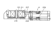
図69は第53の実施の形態例を示すもので、下糸残量検知装置と釜内に収容されているボビンケースとの関係を示した概略断面図である。
この実施の形態例では、リニアアクチュエータを用いた下糸残量検知装置(本出願人の提案に係る特願平7−216143号参照)による下糸残量に対応して、前記ボイスコイルモータ111の駆動による糸調子皿101の糸把持力を変化させる。
図69に示すように、下糸残量検知装置Aは、釜214内のボビン212に巻かれた下糸211に対して、リニアモータの可動部であるコイル組立体205と一体に移動する検知棒207が当接して、下糸211の残量を検知するものであり、208はセンサである。
このようなリニアアクチュエータを用いた下糸残量検知装置Aにより検出される下糸残量に対応して、前記ボイスコイルモータ111の駆動による糸調子皿101の糸把持力を変化させることで、下糸残量が少なくなった時に下糸張力が上がって下調子になるのを防ぐことができる。
【0102】
<第54の実施の形態例>
この第54の実施の形態例は、図示しないが、ミシン主軸の1回転の過程において、前記ボイスコイルモータ111の駆動による糸調子皿101の糸把持力を、例えば、糸締め以外は下げるように変化させ、かつ、その変化タイミングも変える。
このように、ミシン主軸の1回転の過程で、糸締め以外は前記糸調子皿101の糸把持力を下げることによって、柔らかい縫い目が得られ、しかも、前記ボイスコイルモータ111の使用によって糸調子皿101の糸把持力の変化タイミングも変えることができる。
【0103】
<第55の実施の形態例>
図70は第55の実施の形態例を示すもので、環縫いボタン付ミシンによる糸締めを示した要部破断の側面図である。
この実施の形態例では、環縫いボタン付ミシンにおいて、いわゆるアクティブテンション方式のもの(本出願人の提案に係る特願平8−212839号参照)に適用しており、図70中、220は布、221はボタン、222はルーパー、223は針、224は天秤、225は糸張力付与装置、226は糸繰り出し装置、227は上糸、228,229は糸ループである。
【0104】
これによれば、天秤224から針223の間に設けた糸張力付与装置225により上糸227を押さえて、天秤224による上糸227の引き下げ量を制御し、かつ、天秤224により上糸227を引き上げきる前に、糸繰り出し装置226により上糸227を針223側に繰り出すことによって、糸ループ228と布220との隙間lを確保することができる。
従って、次に形成される糸ループ229を従来より大きく形成することができるものである。
以上のようなアクティブテンション方式の環縫いボタン付ミシンにおいて、糸張力付与装置225は、前記ボイスコイルモータ111の駆動による糸調子皿101により構成されて、その糸調子皿101の糸把持力が可変制御されるものとなっている。
【0105】
<第56の実施の形態例>
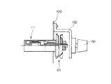
図71は第56の実施の形態例を示すもので、軸線方向に動作する動作軸に糸調子皿を設けた低イナーシャモータとしてのコアレスモータによる糸張力付与装置の要部を示した縦断側面図である。
この図71において、300はミシンアームブロック、301は低イナーシャモータ(コアレスモータ)、302は出力軸、303はリンク、304は継手である。
この実施の形態例では、低イナーシャモータとして前記ボイスコイルモータに代えて、図示のように、コアレスモータ301を用いて、糸調子皿101の糸把持力を可変制御するようにしている。
【0106】
コアレスモータ301は、その内部構造を省略するが、固定の永久磁石と、この永久磁石に対応して設けられ、鉄心を持たないで前記制御電流が供給される回転自在な電機子をケーシングに内蔵して、その電機子の中心部に出力軸302を一体的に備えたものである。
このようなコアレスモータ301は、前述したボイスコイルモータ(VCM)と非常に良く似た特性を有するものであり、その出力軸302の回転運動を直線運動に変換して前記動作軸105に伝えることによって、前記ボイスコイルモータ(VCM)による場合と同様に、コアレスモータ301の駆動による糸調子皿101の糸把持力の前述したような各種制御を行うことができる。
この実施の形態例では、ミシンアームブロック300内に取り付けたコアレスモータ301の出力軸302にリンク303を一体的に備え、このリンク303の先端部に継手304を介して前記動作軸105を連結した構成としている。
ここで、コアレスモータ301の出力軸302から糸調子皿101の動作軸105までの動力伝達機構について、実施の形態例のリンク303及び継手304に代えて、プーリ等の他の機構を用いて回転運動を直線運動に変換するよう構成してもよい。
【0107】
なお、前述したヒステリシスブレーキまたはパウダブレーキによる電磁ブレーキを用いた糸張力制御装置においても、以上のボイスコイルモータまたは運動変換手段を有するコアレスモータによる低イナーシャモータを用いた糸張力制御装置と同様に構成できるものであり、その具体例及び作用効果の説明を省略した。
さらに、以上の実施の各形態例では、制御電流という表現をとっているが、制御電圧に置き換えても同様のことが言える。
【0108】
<第57の実施の形態例>
この第57の実施の形態例は、請求項2記載の発明の具体例に相当するものである。
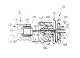
即ち、図72は請求項2記載の発明の具体例に相当する第57の実施の形態例を示すもので、軸線方向に動作する動作軸に回転体制動部材を設けた低イナーシャモータとしてのボイスコイルモータによる糸張力付与装置の要部を示した縦断側面図である。
この図72において、前述した第22の実施の形態例(図33参照)と同様に、100はミシンアームブロック、104は中空軸、105は動作軸、107は軸受ケース、108はコイルバネ、109は糸掛け棒、111は低イナーシャモータ(ボイスコイルモータ)、112は磁気回路、113は円筒型ヨーク、114は永久磁石(外極)、115は鉄心(中央極)、116は可動コイル、117は補償銅管、118はコイル、119はコイルヘッドであり、401は回転体(糸車)、402,403は摩擦体(摩擦板)、404,405は回転体制動部材(押さえ板)、406は当接片である。
【0109】
図72に示すように、前記ボイスコイルモータ111の前記動作軸105が挿入される前記中空軸104上には、回転体である糸車401が回転自在に装着されると共に、この糸車401の両側に摩擦体としての摩擦板402,403がそれぞれ配設されており、さらに、これらの摩擦板402、403の両側には、回転体制動部材である対をなす押さえ板404,405がそれぞれ配設されている。
この回転体制動部材については、中空軸104上に、その先端部のフランジ側に固定の押さえ板404を組み付けて、前記軸受ケース107側に可動の押さえ板405をスライド自在に組み付けている。
そして、中空軸104の内部に設けられて、動作軸105の先端部により押される当接片406は、可動の押さえ板405と一体のものである。
なお、この実施の形態例とは逆に、内側の押さえ板405を固定として、外側の押さえ板404を可動としてもよく、その場合には、当接片406を可動となる外側の押さえ板404と一体に設けて、その当接片406に動作軸105の先端部を係合等により接続することで、動作軸105により当接片406が引かれるようにしておく。
【0110】
以上のような構成の糸張力付与装置によれば、ボイスコイルモータ111の前記可動コイルと116と一体の動作軸105による中空軸104内の前進(または後退)動作によって、当接片406を介して可動の押さえ板405が軸線方向に移動して、固定の押さえ板404との間の隙間を変えて、その間の両側の摩擦板402,403を介して糸車401に対する制動力を変えることができる。
従って、糸車401に巻き付けられる糸に対する張力を変えることができる。
【0111】
なお、このようなボイスコイルモータ111の作動により制動力が付与される糸車401によっても、ボイスコイルモータによる前述した糸調子皿の場合と同様に、前述したような各種制御を行うことができる。
また、このような糸車401において、前述したコアレスモータにより制動力をかけるように構成してもよい。
【0112】
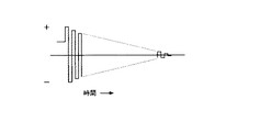
ところで、図73は前記電磁ブレーキ(ヒステリシスブレーキ)を消磁させるための交番磁界のかけ方の一例を示した時間−交番磁界線図である。
即ち、ヒステリシスブレーキは、流す電流を急に変化させると、残留磁気が残り、1回転中にトルク変動が発生する。
そのトルク変動を消すためには、消磁が必要になる。
その消磁には、例として図73に示すように、交番磁界をかけて消磁するが、この時にヒステリシスブレーキが回転してしまう。
この場合、その回転する方向が決まっていないので、糸をゆるめる方向に回転した場合には、糸がゆるんで糸車に巻き付いてしまう。
そこで、消磁するときは、軸が回らないように、機械的もしくは電気的に軸を固定する必要がある。
そのような対策例が、後述するような第58から第60の実施の各形態例である。
【0113】
<第58の実施の形態例>
図74は第58の実施の形態例を示すもので、糸車の軸に軸固定手段を設けた電磁ブレーキとしてのヒステリシスブレーキによる糸張力付与装置の要部を示した部分的破断の斜視図である。
この図74において、前述した第1の実施の形態例(図1参照)と同様に、1は回転体(糸車)、11は電磁ブレーキ(ヒステリシスブレーキ)、12はステータ、12aは外側磁極、12bは内側磁極、13は出力軸、14は励磁コイル、15は回転子(カップ状の永久磁石)であり、500はミシンブロック、501は軸固定手段(電磁ブレーキ)である。
【0114】
図74に示すように、前記糸車1を備える前記ヒステリシスブレーキ11の前記出力軸13に、この出力軸13を一時的に固定可能とする軸固定手段、例えば、出力軸13を制動力により一時的に固定する適宜の電磁ブレーキ501を設けている。
従って、ヒステリシスブレーキ11の前記励磁コイル14を消磁させた場合において、電磁ブレーキ501の作動により出力軸13に制動力をかけて一時的に固定することができる。
【0115】
なお、この実施の形態例では、軸固定手段として電磁ブレーキ501を使用したが、これに限らず、例えば、エア圧によるブレーキや油圧によるブレーキを採用してもよく、他の機械的な軸固定手段を採用してもよい。
また、このような機械的に軸を固定する方法の他、電気的な制御により軸を固定するようにしてもよい。
【0116】
<第59の実施の形態例>
図75は第59の実施の形態例を示すもので、糸車の軸に軸回転方向規制手段を設けた電磁ブレーキとしてのヒステリシスブレーキによる糸張力付与装置の要部を示した部分的破断の斜視図である。
この図75において、前述した第58の実施の形態例(図74参照)と同様に、1は回転体(糸車)、11は電磁ブレーキ(ヒステリシスブレーキ)、12はステータ、12aは外側磁極、12bは内側磁極、13は出力軸、14は励磁コイル、15は回転子(カップ状の永久磁石)、500はミシンブロックであり、502は軸回転方向規制手段(ワンウェイクラッチ)である。
【0117】
図75に示すように、糸車1を備えるヒステリシスブレーキ11の出力軸13の途中に、この出力軸13の図示矢印方向の回転を許容して反対方向、即ち、糸をゆるめる方向の回転を規制する軸回転方向規制手段、例えば、ワンウェイクラッチ502を設けている。
従って、ヒステリシスブレーキ11の励磁コイル14を消磁させた場合において、ワンウェイクラッチ502により出力軸13の図示矢印方向と反対方向(糸をゆるめる方向)の回転を規制することができる。
【0118】
なお、この実施の形態例では、軸回転方向規制手段としてワンウェイクラッチ502を使用したが、これに限らず、例えば、ラチェットを採用してもよく、他の機械的な軸回転方向規制手段を採用してもよい。
【0119】
<第60の実施の形態例>
図76は第60の実施の形態例を示すもので、糸車の軸に軸回転伝達フリー手段を設けた電磁ブレーキとしてのヒステリシスブレーキによる糸張力付与装置の要部を示した部分的破断の斜視図である。
この図76において、前述した第58の実施の形態例(図74参照)と同様に、1は回転体(糸車)、11は電磁ブレーキ(ヒステリシスブレーキ)、12はステータ、12aは外側磁極、12bは内側磁極、13は出力軸、14は励磁コイル、15は回転子(カップ状の永久磁石)、500はミシンブロックであり、503は軸回転伝達フリー手段(電磁クラッチ)である。
【0120】
図76に示すように、糸車1を備えるヒステリシスブレーキ11の出力軸13の途中に、この出力軸13の回転の伝達をフリーにする軸回転伝達フリー手段、例えば、出力軸13の回転の伝達・遮断を可能とする適宜の電磁クラッチ503を設けている。
従って、ヒステリシスブレーキ11の励磁コイル14を消磁させた場合において、電磁クラッチ503の遮断動作によって、出力軸13の回転の伝達をフリーにすることができる。
【0121】
なお、この実施の形態例では、軸回転伝達フリー手段として電磁クラッチ503を使用したが、これに限らず、例えば、ツースクラッチを採用したり、エア圧によるクラッチや油圧によるクラッチを採用してもよく、他の機械的な軸回転伝達フリー手段を採用してもよい。
【0122】
<第61の実施の形態例>
図77は第61の実施の形態例を示すもので、制御処理の一例を示したフローチャートである。
この実施の形態例では、図77のフローチャートに示されるように、前述した第1の実施の形態例での制御処理の一例(図9参照)において、布押え上げ位置の検出と演算処理(ステップS7)に続いて、前記ヒステリシスブレーキ11の前記励磁コイル14を消磁させる(ステップS71)。
そして、次の糸切りの検出と演算処理(ステップS8)に続いても、ヒステリシスブレーキ11の励磁コイル14を消磁させる(ステップS81)。
【0123】
具体的には、ステップS7において、布押え上げ位置が上端に達した時点で、ヒステリシスブレーキ11の励磁コイル14を消磁させるようにする。
なお、その消磁の仕方としては、例えば、ミシンの布押え上げ装置の押え上げ動作に直接連動させたり、または、手元スイッチや押え上げスイッチの押え上げ操作に連動させたり、あるいは、押え上げ動作を行わせるべく膝スイッチの0N動作のための膝上げ操作に連動させるようにすればよい。
従って、布押え上げ動作時におけるヒステリシスブレーキ11のトルク変動を防止できる。
さらに、次のステップS8において、糸切り信号がONになった時点で、ヒステリシスブレーキ11の励磁コイル14を消磁させるようにする。
従って、糸切り動作時におけるヒステリシスブレーキ11のトルク変動を防止できる。
【0124】
<第62の実施の形態例>
図示しないが、この第62の実施の形態例では、ミシンの停止時に、ヒステリシスブレーキ11の励磁コイル14を消磁させる。
具体的には、縫製が終わってミシンが停止した時点で、ヒステリシスブレーキ11の励磁コイル14を消磁させるようにする。
従って、ミシン停止時におけるヒステリシスブレーキ11のトルク変動を防止できる。
【0125】
なお、以上の第58から第62の実施の各形態例では、ヒステリシスブレーキについて説明したが、前述したパウダブレーキの場合でも同様のことが言える。
また、以上に説明した実施の各形態例の他、具体的構成や細部構造等については適宜の変更が許容されるものであることは勿論である。
【0126】
【発明の効果】
以上のように、請求項1記載の発明に係るミシンの糸張力制御装置によれば、縫糸に対する張力付加用の糸調子皿を、低イナーシャモータの駆動により軸線方向に動作する動作軸に設け、低イナーシャモータに動作軸の軸線方向動作力調整用の制御電流を供給して、糸調子皿による縫糸に対する把持力を可変制御する制御電流供給回路を設けてなる構成のため、糸張力付加用の駆動源として、インダクタンスが小さく、慣性も小さく、しかも、駆動力が距離に関係なく一定で、電流値に比例した駆動力が得られ、また、構造が簡単で、電源投入時の原点復帰(イニシャライズ)も不要であるといった利点を得ることができる。
従って、インダクタンス及び慣性が小さいため、応答が早く、高速での糸調子皿の追従性を良くして、高速でも安定した縫目を得ることができ、また、駆動力は距離に関係なく一定で電流値に比例するため、糸調子皿による安定した糸把持力(糸張力)を得て、安定した縫製をすることができ、しかも、電源投入時の原点復帰(イニシャライズ)も不要なため、電気的に糸張力を制御する場合にもその電気制御系を簡単にすることができる。
【0127】
また、請求項2記載の発明に係るミシンの糸張力制御装置によれば、糸張力付加用の回転体に対する回転体制動部材を、低イナーシャモータの駆動により軸線方向に動作する動作軸に設け、低イナーシャモータに動作軸の軸線方向動作力調整用の制御電流を供給して、回転体制動部材による回転体に対する制動力のトルクを可変制御する制御電流供給回路を設けてなる構成のため、糸張力付加用の駆動源として、インダクタンスが小さく、慣性も小さく、しかも、駆動力が距離に関係なく一定で、電流値に比例した駆動力が得られ、また、構造が簡単で、電源投入時の原点復帰(イニシャライズ)も不要であるといった利点を得ることができる。
従って、インダクタンス及び慣性が小さいため、応答が早く、高速での回転体(糸車)の追従性を良くして、高速でも安定した縫目を得ることができ、また、駆動力は距離に関係なく一定で電流値に比例するため、回転体(糸車)による安定した糸張力を得て、安定した縫製をすることができ、しかも、電源投入時の原点復帰(イニシャライズ)も不要なため、電気的に糸張力を制御する場合にもその電気制御系を簡単にすることができる。
【0130】
特に、請求項1、2記載の発明に係るミシンの糸張力制御装置によれば、低イナーシャモータをミシンアームの裏面側に設けたため、糸張力制御装置の駆動源としての低イナーシャモータが、縫製作業の邪魔にならないといった利点を得ることができる。
【図面の簡単な説明】
【図1】 第1の実施の形態例を示すもので、ミシンの縫糸に対する張力の付加を可能とする回転体である糸車を回転子の軸に設けた電磁ブレーキとしてのヒステリシスブレーキによる糸張力付与装置の要部を示した半截側面図である。
【図2】 図1のヒステリシスブレーキの内部構成を示す半截正面図である。
【図3】 図1の糸車に縫糸を巻き付けた状態を示す斜視図である。
【図4】 図1の糸張力付与装置をミシンに装着した状態の糸系統図である。
【図5】 図1の糸張力付与装置による軸回転数−制動トルク特性図である。
【図6】 図1の糸張力付与装置による軸回転角−制動トルク特性図である。
【図7】 図1の糸張力付与装置による励磁電流−制動トルク特性図である。
【図8】 図1の糸張力付与装置を制御する制御装置の構成及びその入出力信号を示すもので、第16の実施の形態例も併せて示した構成図である。
【図9】 図8の制御装置による処理の一例を示したフローチャートである。
【図10】 第2の実施の形態例を示すもので、主軸(上軸)回転数−制動トルク特性図である。
【図11】 第3の実施の形態例を示すもので、主軸(上軸)回転角−制動トルク特性図である。
【図12】 第4の実施の形態例を示すもので、時間−押え上げ信号/制動トルク特性図である。
【図13】 第5の実施の形態例を示すもので、時間−糸切り信号/制動トルク特性図である。
【図14】 第6の実施の形態例を示すもので、時間−バック信号/制動トルク特性図である。
【図15】 第7の実施の形態例を示すもので、縫製開始からの時間−制動トルク特性図である。
【図16】 第8の実施の形態例を示すもので、時間−段部検知信号/制動トルク特性図である。
【図17】 第9の実施の形態例を示すもので、2本針ミシンの要部斜視図である。
【図18】 第10の実施の形態例を示すもので、2本針ミシンによる片針停止を伴う縫製例を示す平面図である。
【図19】 第11の実施の形態例を示すもので、千鳥縫いミシンによる千鳥縫いを例示した平面図である。
【図20】 第12の実施の形態例を示すもので、穴かがりミシンの要部斜視図である。
【図21】 穴かがりミシンによる縫製例を示す平面図である。
【図22】 第13の実施の形態例を示すもので、パターン縫いによるパーフェクトステッチとヒッチステッチが混在した縫製例を示す平面図である。
【図23】 第14の実施の形態例を示すもので、(a)は縫目形式514の縫目を例示した斜視図、(b)は縫目形式506の縫目を例示した斜視図である。
【図24】 図23に続いて第14の実施の形態例を示すもので、(a)は縫目形式504の縫目を例示した斜視図、(b)は縫目形式505の縫目を例示した斜視図である。
【図25】 図24に続いて第14の実施の形態例を示すもので、(a)は縫目形式502の縫目を例示した斜視図、(b)は縫目形式503の縫目を例示した斜視図である。
【図26】 第15の実施の形態例を示すもので、ロックミシンの斜視図である。
【図27】 第17の実施の形態例と第18の実施の形態例とを共に示すもので、縫製装置の一例を示した概略正面図である。
【図28】 第19の実施の形態例と第20の実施の形態例とを共に示すもので、ミシンの要部の一例を示した斜視図である。
【図29】 第1の実施の形態例の変形例である第21の実施の形態例の糸張力付与装置を示す概略構成図である。
【図30】 従来の穴かがりミシンの糸張力付与装置部分を示した要部斜視図である。
【図31】 従来のロックミシンを示した斜視図である。
【図32】 従来の糸調子を示した斜視図である。
【図33】 請求項1、2記載の発明の具体例に相当する第22の実施の形態例を示すもので、軸線方向に動作する動作軸に糸調子皿を設けた低イナーシャモータとしてのボイスコイルモータによる糸張力付与装置の要部を示した縦断側面図である。
【図34】 図33のボイスコイルモータの移動距離−吸引力(推力)特性図である。
【図35】 図33のボイスコイルモータの電流−吸引力(推力)特性図である。
【図36】 図33の糸張力付与装置をミシンに装着した状態の糸系統図である。
【図37】 第23の実施の形態例を示すもので、図33の糸張力付与装置に圧力センサを設けた状態を示した縦断側面図である。
【図38】 図33の糸張力付与装置を制御する制御装置の構成及びその入出力信号を示すもので、第50の実施の形態例も併せて示した構成図である。
【図39】 図38の制御装置による処理の一例を示したフローチャートである。
【図40】 第25の実施の形態例を示すもので、主軸(上軸)回転数−把持力(張力)特性図である。
【図41】 糸締め範囲を併せて示した主軸(上軸)回転数−把持力(張力)特性図である。
【図42】 第26の実施の形態例を示すもので、時間−押さえ上げ信号/把持力(張力)特性図である。
【図43】 第27の実施の形態例を示すもので、時間−糸切り信号/把持力(張力)特性図である。
【図44】 第28の実施の形態例を示すもので、時間−バック信号/把持力(張力)特性図である。
【図45】 第29の実施の形態例を示すもので、時間−把持力(張力)特性図である。
【図46】 第30の実施の形態例を示すもので、時間−段部検知信号/把持力(張力)特性図である。
【図47】 第31の実施の形態例を示すもので、2本針ミシンの要部斜視図である。
【図48】 第32の実施の形態例を示すもので、回転数−把持力(張力)特性図である。
【図49】 第33の実施の形態例を示すもので、2本針ミシンによる片針停止を伴う縫製例を示した平面図である。
【図50】 第34の実施の形態例を示すもので、千鳥縫いミシンによる千鳥縫いを例示した平面図である。
【図51】 第35の実施の形態例を示すもので、穴かがりミシンを示した要部斜視図である。
【図52】 穴かがりミシンによる縫製例を示した平面図である。
【図53】 第36の実施の形態例を示すもので、パターン縫いによるパーフェクトステッチとヒッチステッチが混在する縫製例を示した平面図である。
【図54】 第37の実施の形態例を示すもので、(a)は縫い目形式514の縫い目を例示した斜視図、(b)は縫い目形式506の縫い目を例示した斜視図である。
【図55】 図54に続いて第37の実施の形態例を示すもので、(a)は縫い目形式504の縫い目を例示した斜視図、(b)は縫い目形式505の縫い目を例示した斜視図である。
【図56】 図55に続いて第37の実施の形態例を示すもので、(a)は縫い目形式504の縫い目を例示した斜視図、(b)は縫い目形式503の縫い目を例示した斜視図である。
【図57】 第38の実施の形態例を示すもので、ロックミシンを示した要部斜視図である。
【図58】 第39の実施の形態例を示すもので、(a)は縫製装置の一例を示した要部斜視図、(b)は糸張力付与装置の半部破断側面図である。
【図59】 請求項1、2及び3記載の発明の具体例に相当する第40の実施の形態例を示すもので、ボイスコイルモータから糸調子皿までの駆動機構を示した斜視図である。
【図60】 図59の糸張力付与装置をミシンに組み込んだ状態の一例を示した概略側面図である。
【図61】 第42の実施の形態例を示すもので、図33と同様の糸張力付与装置に糸調子皿の隙間調節手段を設けた例を示した縦断側面図である。
【図62】 第43の実施の形態例を示すもので、主軸(上軸)回転角−送り歯高さ特性図である。
【図63】 第45の実施の形態例を示すもので、(a)は回転数−布枚数に対応する係数のデータカードの一例を示した正面図、(b)は回転数−主軸位相に対応する布枚数に応じたデータカードの一例を示した分解斜視図である。
【図64】 第46の実施の形態例を示すもので、糸張力付与装置の半部を破断して示した要部側面図である。
【図65】 第47の実施の形態例を示すもので、主軸(上軸)回転角−上糸張力/上糸量/ボイスコイルモータ電流特性図である。
【図66】 第49の実施の形態例を示すもので、縫製装置の一例を示した概略正面図である。
【図67】 第51の実施の形態例を示すもので、左針落ち用と右針落ち用の布枚数(布厚)に応じたデータカードの一例を示した分解斜視図である。
【図68】 第52の実施の形態例を示すもので、(a)はウィップ縫いの縫い目を示した平面図、(b)はパール縫いの縫い目を示した平面図である。
【図69】 第53の実施の形態例を示すもので、下糸残量検知装置と釜内に収容されているボビンケースとの関係を示した概略断面図である。
【図70】 第55の実施の形態例を示すもので、環縫いボタン付ミシンによる糸締めを示した要部破断の側面図である。
【図71】 第56の実施の形態例を示すもので、軸線方向に動作する動作軸に糸調子皿を設けた低イナーシャモータとしてのコアレスモータによる糸張力付与装置の要部を示した縦断側面図である。
【図72】 第57の実施の形態例を示すもので、軸線方向に動作する動作軸に回転体制動部材を設けた低イナーシャモータとしてのボイスコイルモータによる糸張力付与装置の要部を示した縦断側面図である。
【図73】 電磁ブレーキ(ヒステリシスブレーキ)を消磁させるための交番磁界のかけ方の一例を示した時間−交番磁界線図である。
【図74】 第58の実施の形態例を示すもので、糸車の軸に軸固定手段を設けた電磁ブレーキとしてのヒステリシスブレーキによる糸張力付与装置の要部を示した部分的破断の斜視図である。
【図75】 第59の実施の形態例を示すもので、糸車の軸に軸回転方向規制手段を設けた電磁ブレーキとしてのヒステリシスブレーキによる糸張力付与装置の要部を示した部分的破断の斜視図である。
【図76】 第60の実施の形態例を示すもので、糸車の軸に軸回転伝達フリー手段を設けた電磁ブレーキとしてのヒステリシスブレーキによる糸張力付与装置の要部を示した部分的破断の斜視図である。
【図77】 第61の実施の形態例を示すもので、制御処理の一例を示したフローチャートである。
【符号の説明】
1 回転体(糸車)
5 上糸
6 糸巻
7 糸取りばね
8 針
9 天秤
10 制御電流供給回路
11 電磁ブレーキ(ヒステリシスブレーキ)
12 ステータ
12a 外側磁極
12b 内側磁極
13 出力軸
14 励磁コイル
15 回転子(カップ状の永久磁石)
21 制御装置
22 サーボモータ
23 表示部
24 記憶装置
51 糸張力表示部(制動トルク表示部)
52 糸張力設定部(設定ボリューム、設定値入力装置)
71 電磁ブレーキ(ヒステリシスブレーキ)
72 出力軸
73 回転体(ローラ)
74 押し付けローラ
75 縫糸
76 ローラホルダ
77 押し付けばね
101 糸調子皿
102 固定皿
103 可動皿
104 中空軸
105 動作軸
106 当接片
110 制御電流供給回路
111 低イナーシャモータ(ボイスコイルモータ)
112 磁気回路
113 円筒型ヨーク
114 永久磁石(外極)
115 鉄心(中央極)
116 可動コイル
119 コイルヘッド
121 圧力検出手段
171 駆動力伝達機構
179 バネ
182 位置調節手段
191 糸張力微量調節用の調節つまみ
201 糸張力表示部(糸把持力表示部)
301 低イナーシャモータ(コアレスモータ)
302 出力軸
303 リンク
401 回転体(糸車)
402,403 摩擦体(摩擦板)
404,405 回転体制動部材(押さえ板)
406 当接片
501 軸固定手段
502 軸回転方向規制手段
503 軸回転伝達フリー手段[0001]
BACKGROUND OF THE INVENTION
The present invention relates to a thread tension control device for a sewing machine using an electromagnetic brake typified by a hysteresis brake and a thread tension control device for a sewing machine using a low inertia motor typified by a voice coil motor.
[0002]
[Prior art]
As an electromagnetic yarn tension applying device in a sewing machine, there is one known from Japanese Patent Publication No. 4-11238.
As shown in FIG. 3 of the publication, the braking portion of this conventional electromagnetic yarn tension applying device is composed of a plurality of poles (eight poles), and an electric coil is provided for each pole. The stator and the rotor are each provided with a plurality of teeth. The teeth are offset from each other except for symmetrical pole teeth.
[0003]
In such a conventional electromagnetic yarn tension applying device, the magnetic flux is maximized when the stator and rotor teeth are in a rotational position where the stator teeth coincide with each other, and the rotating rotor is drawn into this rotational position and is in a stable state. Thus, when the vehicle escapes from this position, it acts as a braking force.
In addition, as shown in FIG. 5 of the publication, there is also a thing with the same structure as a permanent magnet type pulse motor as a braking part of the above conventional electromagnetic yarn tension applying device.
[0004]
In addition, according to Japanese Patent Laid-Open No. 53-42963, there is known a thread tension control device for a sewing machine in which a thread tension plate is directly pulled by a solenoid armature, and Japanese Patent Laid-Open No. 60-83696 discloses a DC motor. An automatic upper thread tension setting device that is decelerated by a gear and that pushes and pulls a thread tension plate by a groove cam is known. According to Japanese Patent Laid-Open No. 1-317477, a thread tension rod (center rod) is operated by an air cylinder. ) Is known, and an automatic thread tension adjusting device for a sewing machine in which a thread tension sleeve is taken in and out by a stepping motor is known from JP-A-2-49688. JP-A-6-170074 discloses an upper thread tension control device for an embroidery sewing machine in which a thread tension plate is pushed and pulled by a stepping motor. To have.
[0005]
[Problems to be solved by the invention]
However, the conventional electromagnetic yarn tension applying device as described above has the following problems.
(1) Although there is no problem at low speed, the inertia of the rotor by the solid member is large, and the follow-up performance of the spinning wheel at high speed (especially, the main shaft rotation of the sewing machine is 1,000 rpm or more) is poor.
(2) In order to use the attracting force of the moving pole that has become a tooth shape, the attracting pole changes each time the rotational position shifts, and the braking force varies.
(3) The difference between the braking force at the time of stopping and the braking force at the time of rotation is large, and when the yarn tension is electrically equalized, the load on the electric control system is very large.
[0006]
As described above, many conventional yarn tension control devices have been proposed, but none of them has been put into practical use except for the upper yarn supply in a high-speed sewing machine.
In the sewing thread tension control device disclosed in Japanese Patent Laid-Open No. 53-42963, a method using a solenoid has been proposed, but the solenoid has the following drawbacks.
(1) Large inductance and slow response.
(2) Since the moving body (armature) is a magnetic body, the inertia is large and the response is slow.
(3) The attraction force (thrust) has the property of changing with the square of the distance. In other words, the tension changes in the case of a spun yarn or wool yarn whose thickness changes, and when the yarn is replaced, the tension decreases extremely for the thick yarn and increases extremely for the thin yarn. There is a problem that it is contrary to the required characteristics. Further, when a link or the like is interposed, there is a problem that a slight deviation in the assembly position is amplified by the square, and thus appears as an extreme tension deviation.
That is, the solenoid cannot be used at a high speed, and further, a gap of the solenoid is added in addition to the current value as a parameter for determining the tension.
[0007]
Further, an upper thread tension automatic setting device of the sewing machine disclosed in Japanese Patent Laid-Open No. 60-83696, a thread tension adjusting device of the sewing machine disclosed in Japanese Patent Laid-Open No. 2-49688, and an embroidery sewing machine disclosed in Japanese Patent Laid-Open No. 6-170074. A method using a DC motor or a stepping motor has been proposed as a yarn tension control device, but these motors have the following drawbacks.
(1) The structure is complicated.
(2) Since the rotational motion is converted into a linear motion, the high-speed followability is poor.
(3) The inertia of the drive unit and mechanism is large and cannot follow at high speed.
(4) Since the actuator itself does not have the ability to detect the position and pressure, the position and pressure information must be read by another means using a sensor or the like when the power is turned on, or the origin return operation must be performed.
That is, the motor cannot be used at a high speed, and the position and pressure must be detected by another means when the power is turned on.
[0008]
Further, a system using an air cylinder has been proposed in the upper thread tension adjusting device of the automatic sewing machine disclosed in JP-A-1-317477. However, the air cylinder system has the following drawbacks.
(1) Even if the air pressure is changed, it takes time until the piston finishes moving, and the followability is poor.
(2) Because both the air cylinder and the spring are compressible, when the pressure is changed transiently, hunting occurs and it takes time to settle.
That is, the air cylinder cannot be used at a high speed, and further has a drawback that it has a high risk of inducing hunting.
[0009]
Accordingly, an object of the present invention is to reduce the inertia of the rotor in the braking portion for enabling the tension to be applied to the sewing thread to improve the follow-up performance of the spinning wheel at high speed, and the braking force is also a torque with respect to the shaft rotation angle. It is an object of the present invention to provide a thread tension control device for a sewing machine that can stabilize a braking torque against a change in shaft rotational speed without fluctuation.
Further, the present invention provides a drive system for allowing tension to be applied to the sewing thread, which has a small inductance and inertia, speeds up the response, improves the follow-up performance of the thread tension plate and the spinning wheel at high speed, Stable gripping force (tension) can be obtained, and in particular, stable gripping force (tension) can be obtained even if the thread thickness changes, and the structure is simple and the origin is restored when the power is turned on. Another object of the present invention is to provide a thread tension control device for a sewing machine that does not require (initialization).
[0010]
[Means for Solving the Problems]
Claims to solve the
A thread tension control device for a sewing machine,
This operating axis is a linear motor including a voice coil motor or an operating axis that operates in the axial direction by driving a low inertia motor by a coreless motor having a motion converting means that converts rotational motion into linear motion and transmits the motion to the operating shaft. A thread tension plate is provided that enables the addition of a thread tension corresponding to a change in gripping force on an upper thread, a lower thread, or a looper thread, which is called a sewing thread, by a change in the distance between the pair of trays corresponding to the axial movement of
A control current supply circuit for supplying a control current for adjusting the axial operation force of the operation shaft to the low inertia motor (voice coil motor or the like) is provided to variably control the gripping force.
[0011]
In this way, a thread tension tray for adding thread tension corresponding to a change in gripping force on the sewing thread due to a change in the distance between the pair of trays is reduced by a linear motor including a voice coil motor or a coreless motor having a motion conversion means. A control current that is provided on the operating shaft that operates in the axial direction by driving the inertia motor, and that supplies a control current for adjusting the operating force in the axial direction of the operating shaft to the low inertia motor to variably control the gripping force on the sewing thread by the thread tension plate Since the thread tension control device of the sewing machine is provided with a supply circuit, a low inertia motor with a linear motor or a coreless motor including a voice coil motor as a drive source for adding a thread tension has low inductance, low inertia, and drive. The force is constant regardless of the distance, a driving force proportional to the current value is obtained, the structure is simple, and the power Homing of time (initialization) is also unnecessary.
And, since the inductance and inertia are small, the response is fast, the followability of the thread tension plate at high speed is good, and stable stitches can be obtained even at high speed, and the driving force is constant regardless of the distance and proportional to the current value Therefore, a stable thread gripping force (thread tension) is obtained by the thread tension plate, which enables stable sewing and eliminates the need for return to origin (initialization) when the power is turned on. The electric control system can be simplified when controlling the motor.
[0012]
Claims 2 The described invention
A thread tension control device for a sewing machine,
The tension of the upper thread, lower thread, or looper thread, which is called the sewing thread, is applied to the operating shaft that operates in the axial direction by driving the low inertia motor by the linear motor including the voice coil motor or the coreless motor having the motion converting means. A friction body that is arranged so as to sandwich a rotating body that can be added, and that allows the braking force to be applied to the rotating body by a change in the distance between the braking members that make a pair according to the axial movement of the operating shaft. A rotating body braking member such as a holding plate is provided,
A control current supply circuit that supplies a control current for adjusting the axial operation force of the operation shaft to the low inertia motor (voice coil motor or the like) is provided to variably control the torque of the braking force.
[0013]
As described above, the rotating body braking member for the rotating body for adding the yarn tension corresponding to the change in the braking force due to the change in the spacing between the pair of braking members, the linear motor including the voice coil motor or the coreless having the motion conversion means. It is provided on the operating shaft that operates in the axial direction by driving the low inertia motor by the motor, and a control current for adjusting the axial operating force of the operating shaft is supplied to the low inertia motor, so that the braking force on the rotating body by the rotating body braking member is reduced. Since the thread tension control device of the sewing machine is provided with a control current supply circuit that variably controls the torque, a low inertia motor using a linear motor or a coreless motor including a voice coil motor as a drive source for adding a thread tension has a small inductance, Inertia is small, and the driving force is constant regardless of the distance, and a driving force proportional to the current value is obtained. , In addition, the structure is simple, the origin return when the power is turned on (initialization) is also unnecessary.
And since the inductance and inertia are small, the response is fast, the followability of the rotating body (spindle) at high speed is good, stable stitches can be obtained even at high speed, and the driving force is constant regardless of the distance and the current value Therefore, stable thread tension from the rotating body (spindle) can be obtained, so that stable sewing can be performed and the return to origin (initialization) when power is turned on is not required. Even in the case of control, the electric control system can be simplified.
[0018]
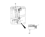
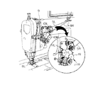
In particular, the
The low inertia motor (voice coil motor or the like) is disposed so as to protrude on the back side opposite to the thread tension plate and a sewing machine arm, and the low inertia motor (voice coil motor or the like) and the thread tension plate. Is connected via a driving force transmission mechanism housed inside the sewing machine arm. It features a configuration.
[0019]
Thus, since the low inertia motor of the yarn tension control device is provided on the back side of the sewing machine arm, the low inertia motor as the drive source of the yarn tension control device does not interfere with the sewing work.
[0020]
DETAILED DESCRIPTION OF THE INVENTION
Hereinafter, embodiments of the thread tension control device for a sewing machine according to the present invention will be described first with reference to FIGS. 1 to 29 and then with reference to FIGS. 33 to 77.
[0021]
<First Embodiment>
First, FIG. 1 is a half side view showing a main part of a yarn tension applying device using a hysteresis brake as an electromagnetic brake in which a spinning wheel which is a rotating body capable of applying tension to a sewing thread of a sewing machine is provided on a shaft of a rotor. FIG. 2 is a half-front view showing the internal configuration of the hysteresis brake.
1 and 2, 1 is a rotating body (spindle wheel), 2a and 2b are half wheel halfs, 3a and 3b are spoke parts, 4 is a meshing part, 11 is an electromagnetic brake (hysteresis brake), 12 is a stator, 12a is an outer magnetic pole, 12b is an inner magnetic pole, 13 is an output shaft, 14 is an exciting coil, and 15 is a rotor (cup-shaped permanent magnet).
[0022]
As shown in FIG. 1, a
The above-described
As shown in FIGS. 1 and 2, the
[0023]
That is, in the
Between the outer magnetic pole 12a and the inner
The outer magnetic pole 12a and the inner
[0024]
FIG. 4 is a yarn system diagram in a state in which the yarn tension applying device using the
Specifically, as shown in the drawing, in the path from which the upper thread 5 is unwound from the
Here, as shown in FIG. 3, when the upper thread 5 is wound around the
[0025]
3 and 4, when the
The control current for the
When the excitation current of the
[0026]
If the
Since this braking force is generated by a continuous change in the polarity of the magnet, the braking force does not change as shown in FIGS. There is no difference.
FIG. 7 shows the braking torque T with respect to the exciting current I of the
[0027]
Next, FIG. 8 shows the configuration of the control device for controlling the above-described yarn tension applying device and its input / output signals. This control device 21 receives various signals (thread trimming signal, sewing machine rotation speed, sewing machine phase) from the outside. Signal, presser height signal, presser lift signal, needle up / down / left / right position signal, back signal, one-needle stop signal, cloth presence / absence signal, etc.) and setting conditions (needle, thread type, thread count, thread manufacturer, cloth as sewing conditions) (Thickness, fabric type, tension, etc.)
The internal CPU (Central Processing Unit) compares the data set in ROM (Read Only Memory) and RAM (Random Access Memory) with a hysteresis brake so that an optimal stitch is obtained. 11, a control signal is output to the servo motor 22 so that the stitches have an appropriate rotation speed, and a message is displayed 23 to the operator.
The control signal data obtained by sewing is stored as a database in a ROM or RAM, and can be replaced by a removable storage device 24 such as a card. Also, a host computer 25 using a LAN (Local Area Network) or a computer network. (Or a server) can also store data.
By performing such control, the nearest data can be derived at the time of the next sewing, so that the setup change time can be shortened.
[0028]
FIG. 9 shows a flowchart as an example of processing by the control device 21 described above.
That is, when a sewing condition is input, a control signal for the maximum number of revolutions is output to the servo motor 22 based on data from the database. If there is no data in the database, first, in step S1, the thread tension is obtained. Enter.
Thereafter, rotation speed detection and calculation processing (step S2), phase detection and calculation processing (step S3), presser foot height detection and calculation processing (step S4), back stitch detection and calculation processing (step S5). , Needle left / right position detection and calculation processing (step S6), cloth presser lifting position detection and calculation processing (step S7), thread trimming detection and calculation processing (step S8), cloth presence / absence detection and calculation processing (step S9) ), Various detection / calculation processes such as one-needle stop detection and calculation process (step S10) are performed.
In step S11, it is determined whether or not to reduce the current yarn tension based on the yarn tension input in step S1. If not, the hysteresis is braked in step S12. 11, after applying a reverse voltage to the control
The above process is performed by a loop process corresponding to the input of the yarn tension.
[0029]
As described above, according to the thread tension control device for a sewing machine according to the first embodiment, the following effects can be obtained.
(1) Since the inertia of the rotor (permanent magnet) 15 is small, the followability of the
(2) The braking force has no torque fluctuation with respect to the shaft rotation angle, and stable sewing can be performed.
(3) Since the braking torque is stable even with respect to changes in the shaft rotational speed, the electric control system can be simplified even when the yarn tension is electrically controlled.
[0030]
Furthermore, the following functions and effects can be generally obtained by electrically controlling the yarn tension.
(4) Since the thread tension is determined by the current value, the thread tension can be expressed numerically. Thereby, since the thread tension can be managed numerically, it is possible to reduce defects in the sewing product.
(5) Since the thread tension is determined by the current value, even after changing the thread tension, the thread tension can be easily reproduced by returning the current value to the original value. Time can be shortened.
(6) Lowering the needle thread tension for the first few stitches at high speed can prevent the needle thread from slipping off, so sewing can be performed at high speed from the first stitch and sewing efficiency is increased.
[0031]
(7) By changing the upper thread tension at the start of sewing, the thread remaining length on the cloth can be changed, so that the quality of the sewing product is improved.
(8) When the braking torque is increased, the upper thread can be prevented from being pulled out. Therefore, when performing corner stitching with a two-needle lockstitch sewing machine or the like with one-needle up (one-needle stop), the sewing product is not tightened correctly during corner stitching. (See FIG. 18).
(9) When the braking torque is set to 0 (zero), the thread tension is also reduced to 0, so that a conventional dish lifting mechanism such as a thread tension is not required, and the mechanism can be simplified. In this way, by setting the braking torque to 0 and the thread tension to 0, it becomes effective at the time of thread trimming, and the cloth can be pulled out easily.
[0032]
(10) When there are a plurality of thread tensions in one thread as in the prior art, and the thread is switched and used at a sewing location (for example, a hooked portion or a parallel portion of a hole sewing) (see FIG. 30) Compared to the above, only one thread tension applying device needs to be adjusted, and the mechanism can be simplified (see FIG. 20).
(11) By combining with a control device such as a computer, automatic control can be performed so that an optimum stitch is always obtained even if various conditions change.
(12) Inertia due to the rotation of the rotary tension (spindle) itself is offset, and sewing unevenness due to the rotational inertia of the rotary tension does not occur.
[0033]
<Second Embodiment>
In the second embodiment, the braking torque of the
That is, for example, when the thread is tightened as the sewing machine rotates at a higher speed, as shown in the main shaft (upper shaft) rotational speed-braking torque characteristic diagram of FIG. As it becomes, the braking torque of the
By performing such control, the same stitch can be obtained even if the rotational speed of the sewing machine is changed.
[0034]
<Third Embodiment>
In the third embodiment, the braking torque of the
That is, for example, as shown in the main shaft (upper shaft) rotation angle-braking torque characteristic diagram of FIG. 11, in one rotation of the upper shaft of the sewing machine, the braking torque of the
By performing such control, a soft stitch can be obtained.
[0035]
<Fourth embodiment>
In the fourth embodiment, the braking torque of the
That is, for example, as shown in the time-presser lift signal / braking torque characteristic diagram of FIG. 12, in a state where a cloth presser (not shown) provided in the sewing machine is raised, the braking torque of the
By performing such control, a cloth (not shown) can be easily pulled out.
[0036]
<Fifth Embodiment>
In the fifth embodiment, the braking torque of the
That is, for example, as shown in the time-thread trimming signal / braking torque characteristic diagram of FIG. 13, when the thread trimming signal is turned ON, the braking torque of the
By performing such control, proper thread trimming is possible, and at the same time, when thread trimming, the upper thread can be fed out from the thread tension applying device until the end of the thread trimming, so the cut thread does not come off the needle. , There is no upper thread missing during thread trimming.
The upper thread length after thread trimming is adjusted by a pretensioning device (not shown) provided in the sewing machine, but can be adjusted by the magnitude of the braking torque of the yarn tension applying device (hysteresis brake 11). The remaining amount of upper thread is reached.
[0037]
<Sixth embodiment>
In the sixth embodiment, the braking torque of the
That is, for example, in the case of back stitching, when the thread is not tightened because it is generally a hitch stitch, when the back signal is ON as shown in the time-back signal / braking torque characteristic diagram of FIG. Increase the braking torque of the
By performing such control, the same stitch can be obtained even in back stitching.
[0038]
<Seventh embodiment>
In the seventh embodiment, the braking torque of the
That is, for example, as shown in the time-braking torque characteristic diagram from the start of sewing in FIG. 15, at the start of sewing, the braking torque of the
By performing such control, the upper thread is sufficiently pulled out from the thread tension applying device (hysteresis brake 11) side at the start of sewing, so that the upper thread end is not drawn and there is no skipping at the start of sewing.
Further, since the thread is likely to fray at the start of sewing, for example, by increasing the braking torque of the
[0039]
<Eighth Embodiment>
In the eighth embodiment, the braking torque of the
That is, for example, when the thread is not tightened by sewing on the thicker stepped portion of the cloth, as shown in the time-stepped portion detection signal / braking torque characteristic diagram of FIG. When this portion is detected, the braking torque of the
By performing such control, it is possible to obtain a seam in which the thread tightening is stable even when sewing is performed on a step portion where the cloth is thick.
[0040]
<Ninth Embodiment>
In the ninth embodiment, a two-needle lockstitch sewing machine is configured so that left and right independent thread tension applying devices (hysteresis brakes 11) are used and each braking torque is variably controlled. is there.
That is, for example, as shown in the perspective view of the main part of the two-needle sewing machine in FIG. 17, the sewing machine head has a spinning wheel 1R and a hysteresis brake 11R for the
By performing such control, the same stitch can be obtained on the left and right.
[0041]
<Tenth Embodiment>
This tenth embodiment uses a thread tension applying device (hysteresis brake 11) that is independent on the left and right sides in a two-needle lockstitch sewing machine (see FIG. 17). The braking torque of the
That is, for example, as shown in the sewing example with one-needle stop by the two-needle sewing machine in FIG. 18, in the case of right-angled corner stitch sewing, several stitches at the corner are sewn only by the left needle, Although the right needle is not sewn, the upper thread is fed out because the cloth is fed.
Therefore, when sewing only the left needle, the braking torque of the thread tension applying device on the right needle side (see hysteresis brake 11R in FIG. 17) is increased.
By performing such control, the same stitch is obtained on both the left and right sides even when sewing starts again without causing the upper thread on the right needle side to be fed out.
[0042]
<Eleventh embodiment>
In the eleventh embodiment, the staggered sewing machine is configured so that the braking torque of the
That is, for example, as shown in the zigzag stitching example by the zigzag stitching machine in FIG. 19, when the thread is tightened by the right needle drop and the thread is not tightened by the left needle drop, the
By performing such control, the same stitch can be obtained with the left and right needle drops.
[0043]
<Twelfth embodiment>
In the twelfth embodiment, in the boring machine, the braking torque of the
That is, for example, as shown in FIG. 30, the conventional boring machine has three thread
By performing such control, two thread tension applying devices together with the pretension device 32 provided in the same manner as in the past, for example, as shown in FIG. 34, 34 stitch adjustments are obtained.
[0044]
<Thirteenth embodiment>
The thirteenth embodiment is configured so that the braking torque of the
In other words, pattern sewing by a home sewing machine, a tack sewing machine, or an automatic machine sewing machine has a cam type and an XY drive type as well known, and sets the braking torque of the
By performing such control, the stitches can be changed depending on the portion to be sewn.
Further, for example, as shown in a sewing example in which perfect stitches and hitch stitches by pattern sewing in FIG. 22 are mixed, by performing control to appropriately change the braking torque of the
[0045]
<Fourteenth embodiment>
In the fourteenth embodiment, the seam is changed by setting the braking torque of the
That is, for example, as shown in examples (a) to (b) of changes in the stitch form in FIG. 23, the
Further, as shown in examples (a) to (b) of changes in the stitch format in FIG. 24, the sewing torque is increased by increasing the braking torque of the
Similarly, as shown in examples (a) to (b) of changes in the stitch form in FIG. 25, the braking torque of the
[0046]
<Fifteenth embodiment>
In the fifteenth embodiment, the lock sewing machine is configured such that the stitches are changed by setting the braking torque of the
That is, for example, as shown in FIG. 31, the conventional lock sewing machine has a total of 4 to 8 thread
By performing such control, a soft chain is obtained by the one-stage yarn
[0047]
<Sixteenth embodiment>
In the sixteenth embodiment, the braking torque of the
That is, for example, the sewing conditions are, as shown in the configuration of the control device in FIG. 8 and its input / output signals, the material of the cloth or thread, the type of thread, the count, etc. In this case, since problems such as puckering occur, the braking torque of the
The
[0048]
<Seventeenth embodiment>
In the seventeenth embodiment, a yarn tension display portion based on the braking torque of the
That is, for example, as shown in an example of the sewing apparatus of FIG. 27, a braking
Thus, when the braking
The yarn tension display section (braking torque display section) 51 is not limited to the
[0049]
<Eighteenth embodiment>
In the eighteenth embodiment, a yarn tension setting portion by the braking torque of the
That is, for example, as shown in the example of the sewing device of FIG. 27, the
As described above, when the yarn
The yarn tension setting unit (setting volume or setting value input device) 52 is not limited to the
[0050]
<Nineteenth embodiment>
In the nineteenth embodiment, the
That is, for example, instead of the
Thus, instead of the conventional thread tension
[0051]
<Twentieth embodiment>
In the twentieth embodiment, the
That is, for example, as shown in an example of the main part of the sewing machine of FIG. 28, the
In this way, if necessary, the sewing machine is provided with a thread
[0052]
<Twenty-first embodiment>
The twenty-first embodiment relates to a modification of the yarn tension applying device in the first embodiment described above. In FIG. 29 showing the schematic configuration, 71 is an electromagnetic brake (hysteresis brake),
That is, as shown in FIG. 29, the hysteresis brake 71 that is an electromagnetic brake is provided with a
That is, the pressing
[0053]
As described above, in the thread tension applying device for the sewing machine, the
Of course, the hysteresis brake 71 in the twenty-first embodiment can provide the same function as the
Further, the hysteresis brake 71 in the twenty-first embodiment is also changed from the second embodiment to the twentieth embodiment in the same manner as the
[0054]
In each of the above embodiments, the hysteresis brake is used as the electromagnetic brake used in the thread tension control device of the sewing machine. However, the present invention is not limited to this, and the same brake can be used even if a powder brake is used. The effect is obtained.
Furthermore, it is needless to say that other specific control methods and specific detailed structures of the sewing machine can be changed as appropriate.
[0055]
Here, the powder brake will be briefly described.
As is well known, a powder brake has a fixed shaft and a rotating shaft arranged on a concentric cylinder with a powder gap therebetween, and a powder (magnetic iron powder) having a high magnetic permeability is placed in the powder gap. An excitation coil is arranged on the outer periphery of the stator so that a magnetic flux flows through the stator.
In the powder brake having such a configuration, if the rotating shaft rotates without excitation, the powder is pressed against the rotating shaft operating surface by centrifugal force, and the rotating shaft and the fixed shaft are not connected at all. When excited, the powders are connected in a chain along the generated magnetic flux, and a braking force acts on the rotating shaft by the connecting force between the powders and the frictional force between the powder and the operating surface.
The powder brake as described above has the features listed below.
(1) A wide range of control is easy. That is, the relationship between the excitation current and the braking torque is almost proportional, and the braking torque can be easily controlled over a wide range.
(2) Continuous slip operation is possible. That is, since a powder is used, the operation surface can be continuously slipped, and a stable slip torque is always obtained regardless of the slip rotation speed.
(3) A stable torque can be obtained. That is, since the powder always works normally due to the shape of the operating surface, the labyrinth shape, etc., a very stable torque can be reproduced even if the current of 0N / 0FF is repeated.
(4) There is no noise. That is, there is no stick-slip on the operating surface as seen in the friction plate system, and no stop sound is generated, so that a quiet operation can be performed.
(5) Large heat capacity. That is, by using a powder having excellent heat resistance and adopting an ideal cooling method, it can be used safely even in severe continuous operation.
(6) Smooth stop / drive is possible. That is, since the static friction coefficient and the dynamic friction coefficient are substantially equal, there is no shock at the time of complete stop, and acceleration / deceleration according to the load can be obtained.
[0056]
In the above embodiment, the yarn tension control device using an electromagnetic brake typified by a hysteresis brake has been described. However, from the following embodiments, a low inertia including a linear motor typified by a voice coil motor is described. A yarn tension control device using a motor will be described.
[0057]
<Twenty-second embodiment>
The twenty-second embodiment is described in
That is, FIG. 2 A twenty-second embodiment corresponding to a specific example of the described invention is shown, and the essential point of a yarn tension applying device using a voice coil motor as a low inertia motor in which a thread tension plate is provided on an operation shaft operating in the axial direction is shown. It is the vertical side view which showed the part.
33, 100 is a sewing machine arm block, 101 is a thread tension plate, 102 is an outer plate (fixed plate), 103 is an inner plate (movable plate), 104 is a hollow shaft, 105 is an operating shaft, and 106 is a contact piece. , 107 is a bearing case, 108 is a coil spring, 109 is a thread hook, 111 is a low inertia motor (voice coil motor), 112 is a magnetic circuit, 113 is a cylindrical yoke, 114 is a permanent magnet (outer pole), and 115 is an iron core (Central pole), 116 is a movable coil, 117 is a compensating copper tube, 118 is a coil, and 119 is a coil head.
[0058]
As shown in FIG. 33, the
Inside the
Contrary to this embodiment, the
The
A
[0059]
The operating
The voice coil motor 111 includes a
The
In the voice coil motor 111 described above, a magnetic field acts on the
[0060]
FIG. 34 shows the moving distance-attraction force (thrust) characteristics of the voice coil motor 111, and FIG. 35 shows the current-attraction force (thrust) characteristics.
That is, the voice coil motor 111 has a characteristic that the inductance is small and the response is fast, and the moving body is only the
Since the voice coil motor 111 has such characteristics, the
[0061]
FIG. 36 is a thread system diagram in a state where the thread tension applying device using the voice coil motor 111 as described above is mounted on the sewing machine. As shown in the drawing, the
Specifically, as shown in the drawing, the amount of the upper thread 5 fed out by the
The control current for the voice coil motor 111 is supplied by a control current supply circuit (CC) 110.
[0062]
Next, FIG. 38 shows the configuration of the control device for controlling the above-described yarn tension applying device and its input / output signals. This control device 21 is connected to various signals (thread trimming signal, sewing machine rotation speed, sewing machine phase) from the outside. Signal, presser height signal, presser lift signal, needle up / down / left / right position signal, back signal, one-needle stop signal, cloth presence / absence signal, etc.) and setting conditions (needle, thread type, thread count, thread manufacturer, cloth as sewing conditions) (Thickness, fabric type, tension, etc.)
Then, the internal CPU compares and calculates the data set in the ROM and RAM, controls the current flowing to the voice coil motor 111 so that an optimal stitch is obtained, and the stitch is suitable for the servo motor 22. A control signal is output so that the number of rotations becomes the same, and a message is displayed 23 to the operator.
The control signal data obtained by sewing is stored as a database in ROM or RAM, and can be replaced by a removable storage device 24 such as a card, or a host computer 25 (or server) using a LAN or computer network. You can also store data.
By performing such control, the closest data can be derived at the time of the next sewing, so that the setup change time is shortened.
[0063]
FIG. 39 shows a flowchart as an example of processing by the control device 21 described above.
That is, when a sewing condition is input, a control signal for the maximum number of revolutions is output to the servo motor 22 based on data from the database. If there is no data in the database, first, in step S1, the thread tension is obtained. Enter.
Thereafter, rotation speed detection and calculation processing (step S2), phase detection and calculation processing (step S3), presser foot height detection and calculation processing (step S4), back stitch detection and calculation processing (step S5). , Needle left / right position detection and calculation processing (step S6), cloth presser lifting position detection and calculation processing (step S7), thread trimming detection and calculation processing (step S8), cloth presence / absence detection and calculation processing (step S9) ), After performing various detection / calculation processes such as detection of one-needle stop and calculation processing (step S10), a control current supplied to the
The above processing is repeated during sewing after the thread tension is input.
[0064]
According to the thread tension control device of the sewing machine using the thread tension device (thread tension plate 101) that controls the gripping force by the voice coil motor 111 according to the above embodiment, the following effects can be obtained.
(1) The inductance is small and the response is fast.
(2) Since the moving body is only the
[0065]
(3) The attractive force (thrust) of the
Accordingly, the following advantages can be obtained.
[1] The tension does not change even in the case of a spun yarn or wool yarn whose thickness changes.
[2] Even if the thread is replaced with a different thickness, the tension does not change significantly.
[3] Even when a driving force transmission mechanism such as a link is interposed, there is no variation in tension even if the assembly position is shifted.
[0066]
(4) The straightness of the current value and tension is good. That is, the tension is uniquely determined by the value of the current that flows.
(5) There is no need to return to the origin when the power is turned on.
(6) A large stroke can be taken, which is suitable for increasing a suction force (thrust) by a driving force transmission mechanism such as a link.
[0067]
The advantages listed above can also be obtained in the same way by a coreless motor, which will be described later, in which the pressure due to the attractive force (thrust) of the voice coil motor 111 is replaced with torque.
[0068]
<Twenty-third embodiment>
FIG. 37 is a longitudinal side view showing a state in which a pressure sensor is provided in the yarn tension applying device of FIG.
In FIG. 37, reference numeral 121 denotes a pressure sensor (pressure detection means), which is provided between the
By such a pressure sensor 121, the pressure acting on the fixed
Thereby, the thread tension can be appropriately controlled while monitoring the pressure acting on the
[0069]
<Twenty-fourth embodiment>
In the twenty-fourth embodiment, although not shown, a yarn tension sensor (yarn tension detecting means) for detecting the yarn tension is provided.
With such a thread tension sensor, the tension applied to the thread by the
Thereby, the yarn tension can be appropriately controlled while monitoring the yarn tension due to the gripping of the
[0070]
<Twenty-fifth embodiment>
In the twenty-fifth embodiment, the yarn gripping force of the
That is, FIG. 40 shows the twenty-fifth embodiment, and is a graph showing the main shaft (upper shaft) rotation speed-gripping force (tension) characteristics.
For example, when the thread is tightened as the sewing machine rotates faster, as shown in FIG. 40, the higher the rotational speed of the upper shaft, which is the main shaft of the sewing machine, is, the higher the speed of the
By performing such control, the same stitch can be obtained even if the rotational speed of the sewing machine is changed.
[0071]
Note that the thread gripping force of the
That is, FIG. 41 is a graph showing the main shaft (upper shaft) rotation speed-gripping force (tension) characteristics together with the thread tightening range.
For example, as shown in FIG. 41, in one rotation of the upper shaft of the sewing machine, the thread gripping force of the
When such control is performed, a soft stitch can be obtained.
[0072]
<Twenty-sixth embodiment>
In the twenty-sixth embodiment, the thread gripping force of the
That is, FIG. 42 shows a twenty-sixth embodiment and is a time-pressing signal / gripping force (tension) characteristic diagram.
For example, as shown in FIG. 42, when the presser foot (not shown) provided in the sewing machine is raised, the thread gripping force of the
By performing such control, a cloth (not shown) can be easily pulled out.
[0073]
<Twenty-seventh embodiment>
In the twenty-seventh embodiment, the thread gripping force of the
That is, FIG. 43 shows a twenty-seventh embodiment and is a time-thread trimming signal / gripping force (tension) characteristic diagram.
For example, as shown in FIG. 43, when the thread trimming signal is turned ON, the thread gripping force of the
Depending on the thread trimming conditions, it may be possible to obtain an appropriate thread tension by arbitrarily changing the thread gripping timing of the
By performing such control, proper thread trimming is possible, and at the same time, when thread trimming, the upper thread can be fed out from the thread tension applying device until the end of the thread trimming, so the cut thread does not come off the needle. , There is no upper thread missing during thread trimming.
The upper thread length after thread trimming is adjusted by a pre-tension device (not shown) provided in the sewing machine, but the thread gripping force of the thread tension applying device (
[0074]
<Twenty-eighth embodiment>
The twenty-eighth embodiment is configured such that the thread gripping force of the
That is, FIG. 44 shows a twenty-eighth embodiment and is a time-back signal / gripping force (tension) characteristic diagram.
For example, when the thread is not tightened because it is generally a hitch stitch at the time of back stitching, as shown in FIG. 44, when the back signal is ON, the voice coil motor 111 holds the thread on the
By performing such control, the same stitch can be obtained even in back stitching.
[0075]
<Twenty-ninth embodiment>
This 29th embodiment is ,Sewing The configuration is such that the thread gripping force of the
That is, FIG. Is the first 29 is a time-gripping force (tension) characteristic diagram showing 29 embodiment examples.
For example, as shown in FIG. 45, at the start of sewing, the thread gripping force of the
By performing such control, the upper thread end is not drawn and the upper thread end is not pulled in, so that the upper thread is sufficiently drawn out from the thread tension applying device (
Further, since the thread is likely to fray at the beginning of sewing, for example, by increasing the thread gripping force of the
[0076]
<Thirty Embodiment>
In the thirtieth embodiment, the yarn gripping force of the
That is, FIG. 46 shows a thirtieth embodiment and is a time-step detection signal / gripping force (tension) characteristic diagram.
For example, in the case where the thread is not tightened by sewing on the thick stepped portion of the cloth, as shown in FIG. 46, when the cloth step detecting device (not shown) detects the stepped portion, the thread tension plate by the voice coil motor 111 is used. Assume that the
By performing such control, it is possible to obtain a seam in which the thread tightening is stable even when sewing is performed on a step portion where the cloth is thick.
[0077]
<Thirty-first embodiment>
In the thirty-first embodiment, in a two-needle lockstitch sewing machine, left and right independent thread tension applying devices (
That is, FIG. 47 shows a thirty-first embodiment and is a perspective view of an essential part of a two-needle sewing machine.
For example, as shown in FIG. 47, a thread tension plate 101R and a voice coil motor 111R for the
By performing such control, the same stitch can be obtained on the left and right.
[0078]
<Thirty-second embodiment>
FIG. 48 shows the thirty-second embodiment and is a characteristic diagram of the rotational speed-gripping force (tension).
In this embodiment, a first thread tensioner (not shown) for pretensioning is provided on the thread supply side (winding side) with respect to the thread tension applying device (the
In this way, as shown in FIG. 48, in the region where the yarn tension does not need to be changed, the yarn tension is exceeded by the first yarn tensioner while being held by the first yarn tensioner similar to the conventional one. In an area where a change in tension is required, the tension of the
[0079]
<Thirty-third embodiment>
This thirty-third embodiment uses an independent thread tension applying device (
That is, FIG. 49 shows a thirty-third embodiment and is a plan view showing an example of sewing accompanied by one-needle stop by a two-needle sewing machine.
For example, as shown in FIG. 49, in the case of right-angled corner stitch sewing, several stitches at the corner are sewn only with the left needle, and the right needle is not sewn, but the cloth is fed, so The thread is fed out.
Therefore, when sewing only the left needle, the thread gripping force of the thread tension applying device on the right needle side (see the thread tension plate 101R by the voice coil motor 111R in FIG. 47) is increased.
By performing such control, the same stitch is obtained on both the left and right sides even when sewing starts again without causing the upper thread on the right needle side to be fed out.
[0080]
<Thirty-fourth embodiment>
The thirty-fourth embodiment is configured such that the thread gripping force of the
That is, FIG. 50 shows a thirty-fourth embodiment and is a plan view illustrating a staggered stitch by a staggered sewing machine.
For example, as shown in the zigzag stitching example of FIG. 50, when the thread is tightened by the right needle drop and the thread is not tightened by the left needle drop, the thread of the
By performing such control, the same stitch can be obtained with the left and right needle drops.
[0081]
<Thirty-fifth embodiment>
The thirty-fifth embodiment is constructed so that the thread gripping force of the
That is, FIG. 51 shows a thirty-fifth embodiment, and is a perspective view showing a main part of a hole sewing machine, and FIG. 52 is a plan view showing an example of sewing by the hole sewing machine.
In this embodiment, for example, as shown in FIG. 51, a single yarn tension applying device (
By performing such control, two yarn tension applying devices in combination with the pretension device 32 provided in the same manner as in the prior art, for example, as shown in FIG. 34, 34 stitch adjustments are obtained.
[0082]
<Thirty-sixth embodiment>
This 36th embodiment The home In the sewing machine for sewing, the barbed sewing machine or the automatic machine sewing machine, the thread gripping force of the
That is, FIG. Is the first 36 is a plan view showing a sewing example in which perfect stitches and hitch stitches by pattern sewing are mixed, showing 36 embodiment examples. FIG.
By the way, as is well known, there are two types of pattern sewing using a home sewing machine, a tack sewing machine, or an automatic machine sewing machine. A cam type and an XY drive type are used. Set the thread gripping force. For example, when the thread is tightly tightened at the time of straight stitching and the thread is to be tightened softly at the embroidery part, the thread gripping force of the
By performing such control, the stitches can be changed depending on the portion to be sewn.
Further, for example, as shown in a sewing example in which perfect stitches and hitch stitches by pattern sewing in FIG. 53 are mixed, by performing control to appropriately change the thread gripping force of the
[0083]
<Thirty-seventh embodiment>
The thirty-seventh embodiment is configured such that the seam is changed by setting the thread gripping force of the
54 to 56 show a thirty-seventh embodiment. FIG. 54 (a) is a perspective view illustrating a seam type 514. FIG. 54 (b) is an example of a seam type 506 seam. 55 (a) is a perspective view illustrating a seam of the seam type 504, FIG. 55 (b) is a perspective view illustrating a seam of the seam type 505, and FIG. 56 (a) is a seam type 504. A perspective view illustrating a seam, and FIG. 56B is a perspective view illustrating a seam of a
For example, as shown in changes (a) to (b) of the stitch form in FIG. 54, the thread by the voice coil motor 111 on the left needle side at the stitch form 514 shown in FIG. 54 (a). When the thread gripping force of the
Also, as shown in examples (a) to (b) of changes in the stitch format of FIG. 55, the
Similarly, as shown in examples (a) to (b) of changes in the stitch format in FIG. 56, the
[0084]
<Thirty-eighth embodiment>
The thirty-eighth embodiment is configured so that the seam is changed in the lock sewing machine by setting the thread gripping force of the
That is, FIG. 57 shows a thirty-eighth embodiment and is a perspective view of a principal part showing a lock sewing machine.
In this embodiment, for example, as shown in FIG. 57, three yarn tension applying devices (
By performing such control, a soft chain is obtained by the one-stage yarn
[0085]
<Thirty-ninth embodiment>
FIG. 58 shows a thirty-ninth embodiment, in which FIG. 58 (a) is a perspective view of an essential part showing an example of a sewing device, and FIG. 58 (b) is a side sectional view of a half portion of the yarn tension applying device.
For example, as shown in FIG. 58, a thread
Thus, instead of the conventional thread tension main body, a thread
Further, the yarn
[0086]
<40th embodiment>
The 40th embodiment is claimed in
That is, FIG. 1, 2, and 3 FIG. 60 is a perspective view showing a drive mechanism from a voice coil motor to a thread tension plate, corresponding to a specific example of the described invention, and FIG. 60 shows the thread tension applying device as a sewing machine; It is the schematic side view which showed an example of the state integrated in.
In this embodiment, as shown in FIG. 59, by providing a
And the voice coil motor 111 is arrange | positioned and fixed to the reverse side opposite to the
[0087]
As shown in FIG. 59, the
The operating
Further, between the
The
[0088]
As described above, first, the voice coil motor 111 is disposed on the back side opposite to the
Then, the driving force is transmitted from the voice coil motor 111 to the operating
Further, for example, even if the control current of the voice coil motor 111 is lowered when the yarn tension is weak, the pressure applied to the voice coil motor 111 is not released by the frictional force of the
In this embodiment, the rotation-
[0089]
<Forty-first embodiment>
Although the forty-first embodiment is not shown, the frictional force of the
Accordingly, since the operating
[0090]
<Forty-second embodiment>
FIG. 61 shows a forty-second embodiment, and is a longitudinal side view showing an example in which a gap adjusting means for a thread tension plate is provided in the same thread tension applying device as FIG.
In this embodiment, a
First, similarly to the above-described yarn tension applying device of FIG. 33, only one of the
Further, the position of the fixed
[0091]
<Forty-third embodiment>
FIG. 62 shows a forty-third embodiment, and is a main shaft (upper shaft) rotation angle-feed dog height characteristic diagram.
In this embodiment, as shown in FIG. 62, the cloth thickness is read in accordance with the height of the cloth presser (not shown) in the phase state when the feed dog (not shown) is sunk, and corresponds to the read cloth thickness. Thus, the thread gripping force of the
Accordingly, the cloth thickness is accurately detected in a state where the feed dog sinks and the cloth presser is lifted by the cloth thickness, and appropriate yarn tension control according to the cloth thickness can be performed.
[0092]
<Forty-fourth embodiment>
In the forty-fourth embodiment, although not shown, the thread gripping force of the
That is, for example, the sewing conditions are, as shown in the configuration of the control device of FIG. 38 and its input / output signals, the material of the cloth or thread, the type of thread, the count, etc., for example, a thin object such as a blouse. In this case, since problems such as puckering occur, the thread gripping force of the
[0093]
<Forty-fifth embodiment>
FIG. 63 shows a forty-fifth embodiment, in which (a) is a front view showing an example of a data card having a coefficient corresponding to the number of rotations-the number of cloths, and (b) corresponds to the number of rotations-spindle phase. It is the disassembled perspective view which showed an example of the data card according to the number of cloth to do.
In this embodiment, with reference to the cloth thickness, as shown in FIG. 63 (a), coefficients corresponding to the number of rotations and the number of cloths are determined in advance, and corresponding to the number of cloths shown in FIG. As shown in b), a data map in which the rotational speed and spindle phase data are determined is input to R0M of the control device of the sewing machine.
Thereby, it is possible to appropriately control the thread gripping force of the
Further, the control current of the voice coil motor 111 may be determined according to setting conditions based on input or selection of cloth, yarn, feed pitch, etc. in an input setting unit (not shown) and the data map.
As described above, even when the control current of the voice coil motor 111 is determined based on the sewing condition and the data map based on the input setting, the gripping force by the
[0094]
<Forty-sixth embodiment>
FIG. 64 shows a forty-sixth embodiment and is a side view of a principal part, with a half part of the yarn tension applying device broken away.
In this embodiment, as shown in FIG. 64, an
As a result, since there is an
[0095]
<Forty-seventh embodiment>
FIG. 65 shows the 47th embodiment, and is a graph of main shaft (upper shaft) rotation angle−upper thread tension / upper thread amount / voice coil motor (VCM) current characteristics.
In this embodiment, a single sewing machine can be used to cover thin objects to thick objects by switching between balance tightening and hook tightening.
Here, generally, it is said that a balance tightening is good for a thin object, and a hook fastening is good for a thick object.
For this reason, the voice coil motor (VCM) current can be switched between the thread gripping force of the
Thus, with a single sewing machine, the voice coil motor (VCM) current can be switched between the balance tightening and the hook tightening to cover from a thin object to a thick object.
[0096]
<Forty-eighth embodiment>
In the forty-eighth embodiment, although not shown in the drawings, the thread gripping force of the
Thus, since the thread gripping force of the
[0097]
<Forty-ninth embodiment>
In the forty-ninth embodiment, a thread tension display portion based on the thread gripping force of the
That is, FIG. 66 shows a forty-ninth embodiment and is a schematic front view showing an example of a sewing apparatus.
For example, as shown in FIG. 66, a
Thus, when the thread gripping
The yarn tension display unit (yarn gripping force display unit) 201 is not limited to the
In the example of FIG. 66, the
As described above, when the yarn
The yarn tension setting unit (setting volume or setting value input device) 202 is not limited to the
[0098]
<50th Embodiment>
In the 50th embodiment, as shown in FIG. 38 described above, a data map in which the thread gripping force of the
Thereby, the data map appropriately set corresponding to the sewing conditions can be input to the control device 21 that controls various functional units including the voice coil motor 111 using the external device.
[0099]
<51st embodiment>
FIG. 67 shows an example of the 51st embodiment, and is an exploded perspective view showing an example of a data card corresponding to the number of cloths (cloth thickness) for left needle drop and right needle drop.
In this embodiment, in the staggered sewing machine, as shown in FIG. 67, the thread gripping of the
Accordingly, for example, when the right needle drop is tightened and the left needle drop is not tightened, the same stitch can be obtained by the left and right needle drops by controlling the gripping force such as raising the left needle drop.
[0100]
<52nd embodiment>
68A and 68B show a fifty-second embodiment, in which FIG. 68A is a plan view showing seams of whipped stitches, and FIG. 68B is a plan view showing seams of pearl stitches.
In this embodiment, pearl stitching and whip stitching can be switched by changing the thread gripping force of the
In other words, by switching only the control current value of the voice coil motor 111, it is possible to switch between the seam of the whip stitch shown in FIG. 68 (a) and the seam of the pearl stitch shown in FIG. 68 (b).
Further, by storing and setting the thread tension of such whipping and pearl sewing, it is possible to switch according to the switch operation corresponding to the sewing, the number of stitches, the feed length, the feed direction, and the like.
[0101]
<53rd Embodiment>
FIG. 69 is a schematic sectional view showing the relationship between the lower thread remaining amount detecting device and the bobbin case housed in the hook, showing the 53rd embodiment.
In this embodiment, the voice coil motor 111 corresponds to the lower thread remaining amount by a lower thread remaining amount detection device using a linear actuator (see Japanese Patent Application No. 7-216143 according to the applicant's proposal). The thread gripping force of the
As shown in FIG. 69, the lower thread remaining amount detection device A detects that the
In response to the lower thread remaining amount detected by the lower thread remaining amount detecting device A using such a linear actuator, by changing the thread gripping force of the
[0102]
<Fifty-fourth embodiment>
In the 54th embodiment, although not shown, the thread gripping force of the
In this way, a soft seam can be obtained by lowering the thread gripping force of the
[0103]
<55th embodiment>
FIG. 70 shows a 55th embodiment, and is a side view of a main part fracture showing thread tightening by a sewing machine with a chain stitch button.
In this embodiment, the sewing machine with a chain stitch button is applied to a so-called active tension type (see Japanese Patent Application No. 8-212839 according to the applicant's proposal). In FIG. 221 is a button, 222 is a looper, 223 is a needle, 224 is a balance, 225 is a thread tension applying device, 226 is a thread feeding device, 227 is an upper thread, and 228 and 229 are thread loops.
[0104]
According to this, the
Therefore, the
In the sewing machine with an active tension type chain stitch button as described above, the thread
[0105]
<56th embodiment>
FIG. 71 shows a fifty-sixth embodiment, and is a longitudinal side view showing a main part of a yarn tension applying device using a coreless motor as a low inertia motor in which a thread tension plate is provided on an operation shaft operating in the axial direction. It is.
In FIG. 71, 300 is a sewing machine arm block, 301 is a low inertia motor (coreless motor), 302 is an output shaft, 303 is a link, and 304 is a joint.
In this embodiment, instead of the voice coil motor as a low inertia motor, a
[0106]
Although the internal structure of the
Such a
In this embodiment, a
Here, the power transmission mechanism from the
[0107]
The above-described yarn tension control device using the electromagnetic brake using the hysteresis brake or the powder brake is configured similarly to the above-described yarn tension control device using the low inertia motor using the voiceless motor or the coreless motor having the motion conversion means. The description of the specific example and an effect was abbreviate | omitted.
Furthermore, although the expression “control current” is used in each of the above embodiments, the same can be said even if it is replaced with a control voltage.
[0108]
<57th embodiment>
The 57th embodiment is claimed in claim 2 This corresponds to a specific example of the described invention.
That is, FIG. 2 A fifty-seventh embodiment corresponding to a specific example of the described invention is shown, in which a yarn tension applying device using a voice coil motor as a low inertia motor provided with a rotating body braking member on an operating shaft operating in the axial direction is shown. It is the vertical side view which showed the principal part.
In FIG. 72, as in the above-described twenty-second embodiment (see FIG. 33), 100 is a sewing machine arm block, 104 is a hollow shaft, 105 is an operating shaft, 107 is a bearing case, 108 is a coil spring, 109 is Yarn stick, 111 is a low inertia motor (voice coil motor), 112 is a magnetic circuit, 113 is a cylindrical yoke, 114 is a permanent magnet (outer pole), 115 is an iron core (center pole), 116 is a movable coil, 117 is Compensation copper pipe, 118 is a coil, 119 is a coil head, 401 is a rotating body (spindle), 402 and 403 are friction bodies (friction plates), 404 and 405 are rotating body braking members (pressing plates), and 406 is a contact It is a piece.
[0109]
As shown in FIG. 72, a
With respect to the rotating body braking member, a fixed pressing plate 404 is assembled on the
A
In contrast to this embodiment, the inner
[0110]
According to the yarn tension applying device having the above-described configuration, the moving
Therefore, the tension on the yarn wound around the
[0111]
Note that the above-described various controls can also be performed by the
Further, such a
[0112]
FIG. 73 is a time-alternating magnetic field diagram showing an example of how to apply an alternating magnetic field for demagnetizing the electromagnetic brake (hysteresis brake).
That is, in the hysteresis brake, if the current to be applied is suddenly changed, residual magnetism remains and torque fluctuation occurs during one rotation.
Degaussing is necessary to eliminate the torque fluctuation.
As an example, the demagnetization is performed by applying an alternating magnetic field as shown in FIG. 73. At this time, the hysteresis brake rotates.
In this case, since the direction of rotation is not determined, when the yarn is rotated in the loosening direction, the yarn loosens and winds around the spinning wheel.
Therefore, when demagnetizing, it is necessary to fix the shaft mechanically or electrically so that the shaft does not rotate.
Such countermeasure examples are the respective 58th to 60th embodiments as will be described later.
[0113]
<The 58th embodiment>
FIG. 74 shows a 58th embodiment, and is a partially broken perspective view showing a main part of a yarn tension applying device using a hysteresis brake as an electromagnetic brake provided with a shaft fixing means on a shaft of a spinning wheel. .
In FIG. 74, as in the first embodiment (see FIG. 1) described above, 1 is a rotating body (spindle wheel), 11 is an electromagnetic brake (hysteresis brake), 12 is a stator, 12a is an outer magnetic pole, and 12b. Is an inner magnetic pole, 13 is an output shaft, 14 is an exciting coil, 15 is a rotor (cup-shaped permanent magnet), 500 is a sewing machine block, and 501 is a shaft fixing means (electromagnetic brake).
[0114]
As shown in FIG. 74, a shaft fixing means for temporarily fixing the
Therefore, when the
[0115]
In this embodiment, the
In addition to such a method of mechanically fixing the shaft, the shaft may be fixed by electrical control.
[0116]
<The 59th embodiment>
FIG. 75 shows a 59th embodiment, and is a partially broken perspective view showing a main part of a yarn tension applying device using a hysteresis brake as an electromagnetic brake provided with a shaft rotation direction restricting means on the shaft of a spinning wheel. It is.
In FIG. 75, as in the above-described 58th embodiment (see FIG. 74), 1 is a rotating body (spindle wheel), 11 is an electromagnetic brake (hysteresis brake), 12 is a stator, 12a is an outer magnetic pole, 12b Is an inner magnetic pole, 13 is an output shaft, 14 is an exciting coil, 15 is a rotor (cup-shaped permanent magnet), 500 is a sewing machine block, and 502 is a shaft rotation direction regulating means (one-way clutch).
[0117]
As shown in FIG. 75, in the middle of the
Therefore, when the
[0118]
In this embodiment, the one-
[0119]
<60th Embodiment>
FIG. 76 shows a 60th embodiment, and is a partially broken perspective view showing a main part of a yarn tension applying device using a hysteresis brake as an electromagnetic brake provided with a shaft rotation transmission free means on a shaft of a spinning wheel. It is.
In FIG. 76, as in the above-described 58th embodiment (see FIG. 74), 1 is a rotating body (spindle wheel), 11 is an electromagnetic brake (hysteresis brake), 12 is a stator, 12a is an outer magnetic pole, 12b Is an inner magnetic pole, 13 is an output shaft, 14 is an exciting coil, 15 is a rotor (cup-shaped permanent magnet), 500 is a sewing machine block, and 503 is a shaft rotation transmission free means (electromagnetic clutch).
[0120]
As shown in FIG. 76, in the middle of the
Therefore, when the
[0121]
In this embodiment, the
[0122]
<61st embodiment>
FIG. 77 shows a 61st embodiment and is a flowchart showing an example of a control process.
In this embodiment, as shown in the flowchart of FIG. 77, in the example of the control processing in the first embodiment described above (see FIG. 9), the presser foot lifting position detection and calculation processing (step Subsequent to S7), the
Even after the next thread trimming detection and calculation process (step S8), the
[0123]
Specifically, in step S7, the
As a method of demagnetization, for example, it is directly linked to the presser lifting operation of the presser foot lifting device of the sewing machine, or linked to the presser lifting operation of the hand switch or the presser lifting switch, or the presser lifting operation is performed. What is necessary is just to make it interlock | cooperate with the knee raising operation for 0N operation | movement of a knee switch to make it perform.
Therefore, the torque fluctuation of the
Further, in the next step S8, when the thread trimming signal is turned ON, the
Therefore, the torque fluctuation of the
[0124]
<62nd embodiment>
Although not shown, in the 62nd embodiment, the
Specifically, when the sewing machine is stopped after the sewing is finished, the
Therefore, the torque fluctuation of the
[0125]
In each of the above 58th to 62nd embodiments, the hysteresis brake has been described, but the same can be said for the powder brake described above.
In addition to the embodiments described above, it is a matter of course that appropriate changes in the specific configuration, detailed structure, and the like are allowed.
[0126]
【The invention's effect】
As described above, the
Accordingly, since the inductance and inertia are small, the response is quick, the followability of the thread tension plate at high speed is improved, and a stable stitch can be obtained even at high speed, and the driving force is constant regardless of the distance. Since it is proportional to the current value, stable thread gripping force (thread tension) can be obtained by the thread tension plate, stable sewing can be performed, and origin return (initialization) when power is turned on is not required. Even when the yarn tension is controlled, the electric control system can be simplified.
[0127]
Claims 2 According to the thread tension control device for a sewing machine according to the described invention, the rotating body braking member for the rotating body for adding the thread tension is provided on the operating shaft that operates in the axial direction by driving the low inertia motor, and operates on the low inertia motor. Drive for adding yarn tension because it is configured to supply a control current for adjusting the operating force in the axial direction of the shaft and variably control the torque of the braking force applied to the rotating body by the rotating body braking member. As a source, the inductance is small, the inertia is small, the driving force is constant regardless of the distance, the driving force proportional to the current value is obtained, the structure is simple, and the origin is restored when the power is turned on (initialization) Can also be obtained.
Therefore, since the inductance and inertia are small, the response is fast, the followability of the rotating body (spindle) at high speed is improved, and a stable seam can be obtained even at high speed, and the driving force is independent of the distance. Since it is constant and proportional to the current value, stable thread tension from the rotating body (thread wheel) can be obtained, stable sewing can be performed, and no return to origin (initialization) is required when the power is turned on. Even when the yarn tension is controlled, the electric control system can be simplified.
[0130]
In particular, the
[Brief description of the drawings]
FIG. 1 shows a first embodiment, and a thread tension is applied by a hysteresis brake as an electromagnetic brake in which a spinning wheel capable of applying a tension to a sewing thread of a sewing machine is provided on a rotor shaft. It is a half-side view which showed the principal part of the apparatus.
FIG. 2 is a half-front view showing the internal configuration of the hysteresis brake shown in FIG.
3 is a perspective view showing a state in which a sewing thread is wound around the spinning wheel of FIG. 1. FIG.
4 is a yarn system diagram in a state where the yarn tension applying device of FIG. 1 is mounted on a sewing machine.
FIG. 5 is a characteristic diagram of shaft rotation speed-braking torque by the yarn tension applying device of FIG. 1;
6 is a characteristic diagram of shaft rotation angle-braking torque by the yarn tension applying device of FIG. 1; FIG.
7 is an excitation current-braking torque characteristic diagram of the yarn tension applying device of FIG. 1. FIG.
FIG. 8 shows a configuration of a control device for controlling the yarn tension applying device of FIG. 1 and its input / output signals, and is a configuration diagram also showing a sixteenth embodiment.
9 is a flowchart showing an example of processing by the control device of FIG.
FIG. 10 shows a second embodiment, and is a main shaft (upper shaft) rotation speed-braking torque characteristic diagram.
FIG. 11 shows a third embodiment, and is a main shaft (upper shaft) rotation angle-braking torque characteristic diagram.
FIG. 12 is a time-presser lift signal / braking torque characteristic diagram showing the fourth embodiment.
FIG. 13 shows a fifth embodiment and is a time-thread trimming signal / braking torque characteristic diagram.
FIG. 14 is a time-back signal / braking torque characteristic diagram showing the sixth embodiment.
FIG. 15 shows a seventh embodiment and is a time-braking torque characteristic diagram from the start of sewing.
FIG. 16 shows an eighth embodiment and is a time-step detection signal / braking torque characteristic diagram.
FIG. 17 is a perspective view showing a main part of a two-needle sewing machine according to a ninth embodiment.
FIG. 18 is a plan view showing a tenth embodiment and showing an example of sewing accompanied by a one-needle stop by a two-needle sewing machine.
FIG. 19 is a plan view illustrating a staggered stitch by a staggered sewing machine according to an eleventh embodiment.
FIG. 20 shows a twelfth embodiment and is a perspective view of the main part of a hole sewing machine.
FIG. 21 is a plan view showing an example of sewing with a hole sewing machine.
FIG. 22 shows a thirteenth embodiment and is a plan view showing a sewing example in which perfect stitches and hitch stitches by pattern sewing are mixed.
23A and 23B show a fourteenth embodiment, in which FIG. 23A is a perspective view illustrating stitches of a stitch type 514, and FIG. 23B is a perspective view illustrating stitches of a stitch type 506; is there.
FIG. 24 shows a fourteenth embodiment following FIG. 23, in which (a) is a perspective view illustrating a seam type 504 seam, and (b) is a seam type 505 seam. It is the illustrated perspective view.
FIG. 25 shows a fourteenth embodiment following FIG. 24, in which (a) is a perspective view illustrating a
FIG. 26 is a perspective view of a lock sewing machine according to a fifteenth embodiment.
FIG. 27 is a schematic front view showing an example of a sewing apparatus, showing both a seventeenth embodiment and an eighteenth embodiment.
FIG. 28 is a perspective view showing an example of a main part of a sewing machine, showing both the nineteenth embodiment and the twentieth embodiment.
FIG. 29 is a schematic configuration diagram showing a yarn tension applying device according to a twenty-first embodiment, which is a modification of the first embodiment.
FIG. 30 is a perspective view of a main part showing a yarn tension applying device portion of a conventional boring machine.
FIG. 31 is a perspective view showing a conventional lock sewing machine.
FIG. 32 is a perspective view showing a conventional thread tension.
FIG. 33
34 is a movement distance-attraction force (thrust) characteristic diagram of the voice coil motor of FIG. 33. FIG.
35 is a current-attraction force (thrust) characteristic diagram of the voice coil motor of FIG. 33. FIG.
36 is a yarn system diagram in a state where the yarn tension applying device of FIG. 33 is attached to the sewing machine.
37 shows a twenty-third embodiment, and is a longitudinal side view showing a state in which a pressure sensor is provided in the yarn tension applying device of FIG. 33. FIG.
FIG. 38 shows a configuration of a control device for controlling the yarn tension applying device of FIG. 33 and its input / output signals, and is a configuration diagram also showing a 50th embodiment.
FIG. 39 is a flowchart showing an example of processing by the control device of FIG. 38;
FIG. 40 shows a twenty-fifth embodiment and is a main shaft (upper shaft) rotation speed-gripping force (tension) characteristic diagram.
FIG. 41 is a graph showing the main shaft (upper shaft) rotation speed-gripping force (tension) characteristic, together with the thread tightening range.
42 shows a twenty-sixth embodiment and is a time-pressing signal / gripping force (tension) characteristic diagram. FIG.
43 shows a twenty-seventh embodiment and is a time-thread trimming signal / gripping force (tension) characteristic diagram. FIG.
FIG. 44 is a time-back signal / gripping force (tension) characteristic diagram according to the twenty-eighth embodiment.
FIG. 45 First 29 is a time-gripping force (tension) characteristic diagram showing 29 embodiment examples.
FIG. 46 shows a thirtieth embodiment and is a time-step detection signal / gripping force (tension) characteristic diagram.
FIG. 47 is a perspective view showing a principal part of a two-needle sewing machine according to a thirty-first embodiment.
FIG. 48 shows a thirty-second embodiment and is a rotational speed-gripping force (tension) characteristic diagram.
FIG. 49 is a plan view showing a thirty-third embodiment and showing an example of sewing involving a one-needle stop by a two-needle sewing machine.
FIG. 50 is a plan view illustrating a thirty-fourth embodiment and illustrating staggered stitches by a staggered sewing machine;
FIG. 51 shows a thirty-fifth embodiment and is a perspective view showing a principal part of a perforated sewing machine.
FIG. 52 is a plan view showing an example of sewing with a hole sewing machine.
FIG. 53 shows a thirty-sixth embodiment and is a plan view showing a sewing example in which perfect stitches and hitch stitches by pattern sewing are mixed.
54A and 54B show a thirty-seventh embodiment, in which FIG. 54A is a perspective view illustrating a seam type 514 seam, and FIG. 54B is a perspective view illustrating a seam type 506 seam;
FIG. 55 shows a thirty-seventh embodiment following FIG. 54, wherein (a) is a perspective view illustrating a seam type 504 seam, and (b) is a perspective view illustrating a seam type 505 seam. It is.
FIG. 56 shows a thirty-seventh embodiment following FIG. 55, in which (a) is a perspective view illustrating a seam type 504 seam, and (b) is a perspective view illustrating a
FIG. 57 is a main part perspective view showing a lock sewing machine according to a thirty-eighth embodiment.
58 shows a thirty-ninth embodiment, in which FIG. 58 (a) is a perspective view of an essential part showing an example of a sewing device, and FIG. 58 (b) is a side sectional view of a half portion of the yarn tension applying device.
FIG. 59
60 is a schematic side view showing an example of a state in which the yarn tension applying device of FIG. 59 is incorporated in a sewing machine.
61 shows a forty-second embodiment, and is a longitudinal side view showing an example in which a thread tension applicator gap adjusting means is provided in the same thread tension applying device as FIG. 33. FIG.
62 shows a forty-third embodiment and is a main shaft (upper shaft) rotation angle-feed dog height characteristic diagram. FIG.
FIG. 63 shows a forty-fifth embodiment, (a) is a front view showing an example of a data card having a coefficient corresponding to the number of revolutions-the number of cloths, and (b) is a diagram showing the number of revolutions-spindle phase. It is the disassembled perspective view which showed an example of the data card according to the number of corresponding cloths.
FIG. 64 is a principal part side view showing the forty-sixth embodiment, with a half part of the yarn tension applying device broken away;
65 shows a forty-seventh embodiment, and is a main shaft (upper shaft) rotation angle−upper thread tension / upper thread amount / voice coil motor current characteristic diagram. FIG.
FIG. 66 is a schematic front view showing an example of a sewing apparatus according to a forty-ninth embodiment.
FIG. 67 is an exploded perspective view showing an example of a data card according to the number of cloths (cloth thickness) for left needle dropping and right needle dropping, showing the fifty-first embodiment.
68A and 68B show a fifty-second embodiment, in which FIG. 68A is a plan view showing seams of whipped stitches, and FIG. 68B is a plan view showing seams of pearl stitches.
FIG. 69 is a schematic sectional view showing the relationship between the lower thread remaining amount detecting device and the bobbin case housed in the hook, showing the 53rd embodiment.
FIG. 70 is a side view of a principal part broken view showing thread fastening by a sewing machine with a chain stitch button according to a 55th embodiment.
FIG. 71 is a longitudinal side view showing the main part of a yarn tension applying device using a coreless motor as a low inertia motor in which a thread tension plate is provided on an operation shaft operating in the axial direction, showing a fifty-sixth embodiment; FIG.
FIG. 72 shows a 57th embodiment and shows a main part of a yarn tension applying device using a voice coil motor as a low inertia motor in which a rotating body braking member is provided on an operating shaft operating in the axial direction. It is a vertical side view.
FIG. 73 is a time-alternating magnetic field diagram showing an example of how to apply an alternating magnetic field for demagnetizing an electromagnetic brake (hysteresis brake).
74 is a partially broken perspective view showing a main part of a yarn tension applying device using a hysteresis brake as an electromagnetic brake having a shaft fixing means provided on a shaft of a spinning wheel according to a 58th embodiment. FIG. is there.
75 shows a 59th embodiment, and is a partially broken perspective view showing a main part of a yarn tension applying device using a hysteresis brake as an electromagnetic brake provided with an axial rotation direction restricting means on a shaft of a spinning wheel. FIG. FIG.
FIG. 76 shows a 60th embodiment, and is a partially broken perspective view showing a main part of a yarn tension applying device using a hysteresis brake as an electromagnetic brake provided with a shaft rotation transmission free means on a shaft of a spinning wheel. FIG.
FIG. 77 is a flowchart illustrating an example of control processing according to the 61st embodiment.
[Explanation of symbols]
1 Rotating body (spindle wheel)
5 Upper thread
6 spools
7 Thread take-up spring
8 needles
9 Balance
10 Control current supply circuit
11 Electromagnetic brake (hysteresis brake)
12 Stator
12a Outer magnetic pole
12b Inner magnetic pole
13 Output shaft
14 Excitation coil
15 Rotor (cup-shaped permanent magnet)
21 Control device
22 Servo motor
23 Display
24 storage devices
51 Yarn tension display (braking torque display)
52 Yarn tension setting section (setting volume, setting value input device)
71 Electromagnetic brake (hysteresis brake)
72 Output shaft
73 Rotating body (roller)
74 Pressing roller
75 Sewing thread
76 Roller holder
77 Pressing spring
101 Thread tension plate
102 fixed plate
103 Movable dish
104 hollow shaft
105 Operation axis
106 Contact piece
110 Control current supply circuit
111 Low inertia motor (voice coil motor)
112 Magnetic circuit
113 Cylindrical yoke
114 Permanent magnet (outer pole)
115 Iron core (central pole)
116 Moving coil
119 Coil head
121 Pressure detection means
171 Drive force transmission mechanism
179 Spring
182 Position adjustment means
191 Adjustment knob for fine adjustment of thread tension
201 Thread tension display section (Thread gripping force display section)
301 Low inertia motor (coreless motor)
302 Output shaft
303 links
401 Rotating body (spindle)
402,403 friction body (friction plate)
404,405 Rotating body braking member (pressing plate)
406 Contact piece
501 Shaft fixing means
502 Shaft rotation direction regulating means
503 Shaft rotation transmission free means
Claims (3)
前記低イナーシャモータは、前記糸調子皿とミシンアームを挟んで反対側の裏面側に突出して配置されるとともに、前記低イナーシャモータと前記糸調子皿とは、ミシンアームの内部に収容された駆動力伝達機構を介して連結されていることを特徴とするミシンの糸張力制御装置。Changes in the distance between the pair of plates corresponding to the axial movement of this operating shaft on the operating shaft that operates in the axial direction by driving a low inertia motor by a linear motor including a voice coil motor or a coreless motor having motion conversion means A control current supply circuit that provides a thread tension plate that enables the addition of a thread tension corresponding to a change in the gripping force with respect to the sewing thread, and that supplies a control current for adjusting the axial operation force of the operation shaft to the low inertia motor In a thread tension control device for a sewing machine that variably controls the gripping force,
The low inertia motor is disposed so as to protrude on the reverse side opposite to the thread tension plate and a sewing machine arm, and the low inertia motor and the thread tension plate are driven inside the sewing machine arm. A thread tension control device for a sewing machine, which is connected through a force transmission mechanism .
前記低イナーシャモータは、前記糸調子皿とミシンアームを挟んで反対側の裏面側に突出して配置されるとともに、前記低イナーシャモータと前記糸調子皿とは、ミシンアームの内部に収容された駆動力伝達機構を介して連結されていることを特徴とするミシンの糸張力制御装置。A rotating body capable of applying tension to the sewing thread by adding braking force is sandwiched between operating axes that operate in the axial direction by driving a low inertia motor by a linear motor including a voice coil motor or a coreless motor having motion conversion means. Provided with a rotating body braking member that allows the braking force to be applied to the rotating body by a change in the distance between the braking members that make a pair according to the axial movement of the operating shaft, and the low inertia motor In a thread tension control device for a sewing machine, provided with a control current supply circuit for supplying a control current for adjusting the axial direction operating force of the operating shaft, and variably controlling the torque of the braking force,
The low inertia motor is disposed so as to protrude on the reverse side opposite to the thread tension plate and a sewing machine arm, and the low inertia motor and the thread tension plate are driven inside the sewing machine arm. A thread tension control device for a sewing machine, which is connected through a force transmission mechanism .
Priority Applications (1)
| Application Number | Priority Date | Filing Date | Title |
|---|---|---|---|
| JP22553496A JP4079286B2 (en) | 1995-12-13 | 1996-08-27 | Sewing thread tension control device |
Applications Claiming Priority (3)
| Application Number | Priority Date | Filing Date | Title |
|---|---|---|---|
| JP32427995 | 1995-12-13 | ||
| JP7-324279 | 1995-12-13 | ||
| JP22553496A JP4079286B2 (en) | 1995-12-13 | 1996-08-27 | Sewing thread tension control device |
Publications (2)
| Publication Number | Publication Date |
|---|---|
| JPH09220391A JPH09220391A (en) | 1997-08-26 |
| JP4079286B2 true JP4079286B2 (en) | 2008-04-23 |
Family
ID=26526698
Family Applications (1)
| Application Number | Title | Priority Date | Filing Date |
|---|---|---|---|
| JP22553496A Expired - Fee Related JP4079286B2 (en) | 1995-12-13 | 1996-08-27 | Sewing thread tension control device |
Country Status (1)
| Country | Link |
|---|---|
| JP (1) | JP4079286B2 (en) |
Cited By (2)
| Publication number | Priority date | Publication date | Assignee | Title |
|---|---|---|---|---|
| CN102071548A (en) * | 2011-02-13 | 2011-05-25 | 浙江越隆缝制设备有限公司 | Tension adjuster of belt thread pressing device for towel embroidering machine |
| CN105332177A (en) * | 2015-12-02 | 2016-02-17 | 深圳思瑞普科技有限公司 | Method for automatically adjusting tension of embroidery threads of embroidery machine |
Families Citing this family (13)
| Publication number | Priority date | Publication date | Assignee | Title |
|---|---|---|---|---|
| JP4046431B2 (en) * | 1999-01-18 | 2008-02-13 | Juki株式会社 | Sewing thread tension device |
| JP4043642B2 (en) * | 1999-04-20 | 2008-02-06 | Juki株式会社 | Sewing thread tension device by electromagnetic solenoid |
| JP4903316B2 (en) * | 2000-05-29 | 2012-03-28 | Juki株式会社 | sewing machine |
| JP2006230465A (en) * | 2005-02-22 | 2006-09-07 | Brother Ind Ltd | Buttonholing machine |
| JP2007202833A (en) | 2006-02-02 | 2007-08-16 | Juki Corp | Thread tension device of sewing machine |
| JP5993160B2 (en) | 2011-04-01 | 2016-09-14 | Juki株式会社 | sewing machine |
| CN102505381A (en) * | 2011-11-22 | 2012-06-20 | 惠州神田精密机械有限公司 | Real-time monitoring method and monitoring system for thread condition of computerized embroidery machine |
| CN102634938B (en) * | 2012-05-05 | 2013-01-30 | 宁波舒普机电科技有限公司 | Yarn trapper for sewing machine |
| CN107956051A (en) * | 2017-12-30 | 2018-04-24 | 宁波舒普机电股份有限公司 | A kind of tension disk for automatically adjusting tension force of facial suture |
| JP2019166038A (en) * | 2018-03-23 | 2019-10-03 | ブラザー工業株式会社 | sewing machine |
| JP7224129B2 (en) * | 2018-09-14 | 2023-02-17 | Juki株式会社 | rotary thread tension device |
| JP2020074995A (en) | 2018-11-09 | 2020-05-21 | Juki株式会社 | Zigzag stitch sewing machine |
| TWI699087B (en) * | 2019-12-13 | 2020-07-11 | 點晶科技股份有限公司 | Voice coil motor driving device and control signal providing method |
Family Cites Families (27)
| Publication number | Priority date | Publication date | Assignee | Title |
|---|---|---|---|---|
| US4016441A (en) * | 1976-05-19 | 1977-04-05 | The Singer Company | Linear motor |
| JPS5342963A (en) * | 1976-09-28 | 1978-04-18 | Tokyo Juki Industrial Co Ltd | Yarn tension controller for sewing machine |
| US4214539A (en) * | 1978-09-21 | 1980-07-29 | The Singer Company | Position sensing device for electronic sewing machine |
| JPS56148379A (en) * | 1980-04-17 | 1981-11-17 | Brother Ind Ltd | Sewing machine |
| JPS573679A (en) * | 1980-05-14 | 1982-01-09 | Singer Co | Tuning device for cotton of sewing machine |
| JPS5739878A (en) * | 1980-08-25 | 1982-03-05 | Tokyo Juki Industrial Co Ltd | Toning mechanism for cotton of sewing machine |
| JPS57191261U (en) * | 1981-05-30 | 1982-12-04 | ||
| JPS6033553U (en) * | 1983-08-09 | 1985-03-07 | 東レエンジニアリング株式会社 | Wire tension control device |
| JPS6083696A (en) * | 1983-10-17 | 1985-05-11 | リツカー株式会社 | Needle thread tension force automatic setter of sewing machine |
| JPS60148587A (en) * | 1984-01-13 | 1985-08-05 | 蛇の目ミシン工業株式会社 | Electromagnetical yarn tension imparting apparatus in sewingmachine |
| JPS61100292A (en) * | 1984-10-23 | 1986-05-19 | アイシン精機株式会社 | Yarn loosening machanism of cycle sewing machine |
| JPS6384599A (en) * | 1986-09-29 | 1988-04-15 | ジューキ株式会社 | Stitch balancing thread tension setting apparatus of sewing machine |
| JPS63168200A (en) * | 1986-12-29 | 1988-07-12 | ブラザー工業株式会社 | Needle thread thrust preventing apparatus in sewing machine |
| JP2681635B2 (en) * | 1987-05-13 | 1997-11-26 | オリエンタル酵母工業株式会社 | Method to improve analysis sensitivity and accuracy |
| JPH0249688A (en) * | 1988-05-23 | 1990-02-20 | Mitsubishi Electric Corp | Thread tension adjuster of sewing machine |
| JPH01317477A (en) * | 1988-06-17 | 1989-12-22 | Mitsubishi Electric Corp | Upper thread tension adjusting device for automatic sewing machine |
| JPH03251286A (en) * | 1990-02-28 | 1991-11-08 | Juki Corp | Cycle sewing machine |
| JPH0473091A (en) * | 1990-07-16 | 1992-03-09 | Mitsubishi Electric Corp | Controller for tension of needle thread in sewing machine |
| JPH04242689A (en) * | 1990-12-29 | 1992-08-31 | Brother Ind Ltd | Data origination device sewn products manufacturing |
| JPH06170074A (en) * | 1992-10-08 | 1994-06-21 | Tokai Ind Sewing Mach Co Ltd | Needle thread tension controller of embroidery sewing machine |
| JP3516024B2 (en) * | 1993-06-21 | 2004-04-05 | 東海工業ミシン株式会社 | sewing machine |
| US5603462A (en) * | 1993-09-09 | 1997-02-18 | Melco Industries, Inc. | Changing threads in a sewing machine |
| JPH07178275A (en) * | 1993-12-21 | 1995-07-18 | Brother Ind Ltd | Device for detecting thread tension of sewing machine |
| JP3887680B2 (en) * | 1994-04-07 | 2007-02-28 | 株式会社バルダン | Method and apparatus for controlling needle thread tension of sewing machine |
| JPH07309533A (en) * | 1994-05-13 | 1995-11-28 | Ogura Clutch Co Ltd | Control circuit tensile strength adjusting device and electromagnetic hysteresis brake for the device |
| JP3670059B2 (en) * | 1995-08-24 | 2005-07-13 | ジューキ株式会社 | Lower thread remaining amount detection device for sewing machine |
| JPH09276577A (en) * | 1996-04-08 | 1997-10-28 | Nippon Denpa Kk | Needle thread tension adjusting device of sewing machine |
-
1996
- 1996-08-27 JP JP22553496A patent/JP4079286B2/en not_active Expired - Fee Related
Cited By (3)
| Publication number | Priority date | Publication date | Assignee | Title |
|---|---|---|---|---|
| CN102071548A (en) * | 2011-02-13 | 2011-05-25 | 浙江越隆缝制设备有限公司 | Tension adjuster of belt thread pressing device for towel embroidering machine |
| CN102071548B (en) * | 2011-02-13 | 2013-09-04 | 浙江越隆缝制设备有限公司 | Tension adjuster of belt thread pressing device for towel embroidering machine |
| CN105332177A (en) * | 2015-12-02 | 2016-02-17 | 深圳思瑞普科技有限公司 | Method for automatically adjusting tension of embroidery threads of embroidery machine |
Also Published As
| Publication number | Publication date |
|---|---|
| JPH09220391A (en) | 1997-08-26 |
Similar Documents
| Publication | Publication Date | Title |
|---|---|---|
| JP4079286B2 (en) | Sewing thread tension control device | |
| WO2010147023A1 (en) | Lower-thread tension control device for sewing machine, and sewing machine | |
| KR101524953B1 (en) | Sewing machine | |
| KR20070111425A (en) | Thread-tension device of a sewing machine | |
| JP4072647B2 (en) | Tension adjustment mechanism for cords | |
| JP2001170385A (en) | Buttonhole sewing machine | |
| JP4043642B2 (en) | Sewing thread tension device by electromagnetic solenoid | |
| JP2007202679A (en) | Thread tension device of sewing machine | |
| JP2003010581A (en) | Thread tension adjustor for sewing machine | |
| JP5085816B2 (en) | Device for controlling the yarn tension of yarn running on an automatic winder | |
| JP2008023047A (en) | Bobbin thread tension control device | |
| JP5253980B2 (en) | Lower thread tension control device | |
| JPH0568764A (en) | Bobbin thread controlling device for sewing machine | |
| CN113089200B (en) | Intelligent thread tension balancing device and sewing machine | |
| JP2007202833A (en) | Thread tension device of sewing machine | |
| JP3537251B2 (en) | Wire tension generator of wire electric discharge machine | |
| JP2850591B2 (en) | Needle bar drive of sewing machine | |
| JP5197129B2 (en) | Lower thread tension control device | |
| JP3573164B2 (en) | Wire tension control device | |
| JP2001327785A (en) | Thread tension device for sewing machine | |
| JP2002282570A (en) | Stitch balancing thread tension device and sewing machine | |
| JPS5823946A (en) | Apparatus for pulling material of knitted fabric | |
| JP2910121B2 (en) | Sewing thread feeding device | |
| JPH06260362A (en) | Winding machine for toroidal coil | |
| JPS62176486A (en) | Stitch balancing thread tension apparatus in sewing machine |
Legal Events
| Date | Code | Title | Description |
|---|---|---|---|
| A131 | Notification of reasons for refusal |
Free format text: JAPANESE INTERMEDIATE CODE: A131 Effective date: 20051101 |
|
| A521 | Written amendment |
Free format text: JAPANESE INTERMEDIATE CODE: A523 Effective date: 20051227 |
|
| A02 | Decision of refusal |
Free format text: JAPANESE INTERMEDIATE CODE: A02 Effective date: 20060530 |
|
| A521 | Written amendment |
Free format text: JAPANESE INTERMEDIATE CODE: A523 Effective date: 20060622 |
|
| A911 | Transfer of reconsideration by examiner before appeal (zenchi) |
Free format text: JAPANESE INTERMEDIATE CODE: A911 Effective date: 20060728 |
|
| A912 | Removal of reconsideration by examiner before appeal (zenchi) |
Free format text: JAPANESE INTERMEDIATE CODE: A912 Effective date: 20060818 |
|
| A61 | First payment of annual fees (during grant procedure) |
Free format text: JAPANESE INTERMEDIATE CODE: A61 Effective date: 20080131 |
|
| FPAY | Renewal fee payment (event date is renewal date of database) |
Free format text: PAYMENT UNTIL: 20110215 Year of fee payment: 3 |
|
| R150 | Certificate of patent or registration of utility model |
Free format text: JAPANESE INTERMEDIATE CODE: R150 |
|
| FPAY | Renewal fee payment (event date is renewal date of database) |
Free format text: PAYMENT UNTIL: 20120215 Year of fee payment: 4 |
|
| FPAY | Renewal fee payment (event date is renewal date of database) |
Free format text: PAYMENT UNTIL: 20120215 Year of fee payment: 4 |
|
| FPAY | Renewal fee payment (event date is renewal date of database) |
Free format text: PAYMENT UNTIL: 20130215 Year of fee payment: 5 |
|
| LAPS | Cancellation because of no payment of annual fees |