JP4078741B2 - Solid-state imaging device, driving method thereof, and camera system - Google Patents
Solid-state imaging device, driving method thereof, and camera system Download PDFInfo
- Publication number
- JP4078741B2 JP4078741B2 JP00155899A JP155899A JP4078741B2 JP 4078741 B2 JP4078741 B2 JP 4078741B2 JP 00155899 A JP00155899 A JP 00155899A JP 155899 A JP155899 A JP 155899A JP 4078741 B2 JP4078741 B2 JP 4078741B2
- Authority
- JP
- Japan
- Prior art keywords
- imaging device
- solid
- state imaging
- transfer
- pixels
- Prior art date
- Legal status (The legal status is an assumption and is not a legal conclusion. Google has not performed a legal analysis and makes no representation as to the accuracy of the status listed.)
- Expired - Fee Related
Links
Images


Landscapes
- Color Television Image Signal Generators (AREA)
- Solid State Image Pick-Up Elements (AREA)
Description
【0001】
【発明の属する技術分野】
本発明は、固体撮像装置およびその駆動方法並びにカメラシステムに関し、特に静止画と動画の双方を得ることが可能な固体撮像装置およびその駆動方法、当該固体撮像装置を撮像デバイスとして用いたカメラシステムに関する。
【0002】
【従来の技術】
スチルカメラに代表される静止画の撮像技術において、撮像デバイスとして固体撮像装置、例えばIT(インターライン転送)方式のCCD(Charge Coupled Device) イメージャを用い、メカニカルシャッター(以下、メカシャッターと略称する)を使ってフレーム読み出しを行い、信号処理系で2フィールド分の画素情報を合成することにより、静止画を構成する方法が知られている。そして、高解像度化のために、より多画素のCCDイメージャが用いられる。
【0003】
一方、被写体をモニタリングする際には、モニターに動画を映し出すモニタリングモード(動画モード)が設定される。ところが、CCDイメージャの出力部では、出力部を構成するソースフォロワのカットオフ周波数とCCD駆動周波数との間に制約条件があることから、出力部をあまり高速にできないため、CCDイメージャの多画素化に伴って画素数が増えることにより、モニタリングモードでのフレームレートが低下することになる。
【0004】
ところで、オートフォーカスやオートアイリスでは、フレームレートとして30枚/秒が必要である。これに対して、例えば200万画素のCCDイメージャでは、フレームレートが5枚/秒程度である。このため、200万画素のCCDイメージャを用いたカメラシステムでは、モニタリングモードを設定した際に、画素情報を間引いて読み出す、いわゆる間引き読み出し駆動を行うことによって30枚/秒のフレームレートを実現するようにしている。
【0005】
【発明が解決しようとする課題】
しかしながら、上述したように、静止画を得る全画素モード(静止画モード)ではフレーム読み出し駆動を行う一方、モニタリングモードでは間引き読み出し駆動を行う構成の従来技術にあっては、信号電荷の読み出しや転送のための駆動が全画素モードとモニタリングモードで異なるため、クロックを含む駆動系の構成が複雑になるという課題がある。
【0006】
また、モニタリングモードでは、全画素モードに比べて露光時間が短くなるので、その分だけ感度が低下することになる。この露光時間の短縮に伴う感度の低下分については、隣接する画素の信号電荷を加算することによって抑えることが可能である。しかしながら、カラーCCDイメージャにおいて、ベイヤー配列のように、隣り合う色が異なるカラーコーディングの場合には、隣接する画素の信号同士を加算することができないため、モニタリングモードでの露光時間の短縮に伴う感度の低下を抑えることができず、モニタリングモードでの感度が全画素モードでの感度と比較して低下するという課題があった。
【0007】
本発明は、上記課題に鑑みてなされたものであり、その目的とするところは、全画素モードとモニタリングモードで駆動系を共通化できる固体撮像装置およびその駆動方法、並びに当該固体撮像装置を撮像デバイスとして用いたカメラシステムを提供することにある。
【0008】
【課題を解決するための手段】
本発明による固体撮像装置は、行列状に配置された画素に対して行方向において同じ色がn画素(nは2以上の整数)ごとに繰り返して配列されたカラーコーディングのカラーフィルタと、(n+1):1のインターレースを行って1フレームを(n+1)フィールドで構成し、(n+1)×m相(mは自然数)のクロックによって信号電荷の垂直転送を行う駆動系とを備えた構成となっている。
【0009】
本発明による固体撮像装置の駆動方法は、行列状に配置された画素に対して行方向において同じ色がn画素ごとに繰り返して配列されたカラーコーディングのカラーフィルタを備えた固体撮像装置において、(n+1):1のインターレースを行って1フレームを(n+1)フィールドで構成し、(n+1)×m相のクロックによって信号電荷の垂直転送を行うようにする。
【0010】
本発明によるカメラシステムは、上記構成の固体撮像装置を撮像デバイスとして用いるとともに、全画素モードとモニタリングモードを選択的に設定するモード設定部を備える。そして、タイミングコントローラでは、モード設定部で設定された撮像モードに応じて固体撮像装置のタイミング制御やメカシャッターの開閉制御を行う一方、全画素モード設定時には信号処理回路で処理された信号に基づく画像情報を記録媒体に静止画情報として記録し、モニタリングモード設定時には信号処理回路で処理された信号に基づく動画をモニターに表示する。
【0011】
【発明の実施の形態】
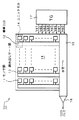
以下、本発明の実施の形態について図面を参照して詳細に説明する。図1は、本発明の第1実施形態に係る例えばIT方式のカラーCCDイメージャを示す概略構成図である。
【0012】
図1において、入射光をその光量に応じた電荷量の信号電荷に変換して蓄積するセンサ部(画素)11が多数、垂直(行)方向および水平(列)方向に2次元マトリクス状に配列されている。また、これらセンサ部11の垂直列ごとに複数本の垂直CCD12が設けられ、さらにこれら垂直CCD12と各センサ部11との間には読み出しゲート部13が介在している。
【0013】
複数個のセンサ部11に蓄積された信号電荷は、後述する読み出しパルスXSGが読み出しゲート部13に印加され、当該読み出しゲート部13のポテンシャルが深くなることによって垂直CCD12に読み出される。垂直CCD12は、例えば6相の垂直転送クロックVφ1〜Vφ6によって転送駆動され、読み出された信号電荷を順に垂直転送する。そして、1つのセンサ部11、それに対応する垂直CCD12の転送段および読み出しゲート部13がユニットセル14となる。
【0014】
6相駆動の垂直CCD12では、例えば、2相目、4相目および6相目の垂直転送クロックVφ2,Vφ4およびVφ6が印加される転送電極が、読み出しゲート部13のゲート電極を兼ねた構造となっている。このことから、6相の垂直転送クロックVφ1〜Vφ6のうち、垂直転送クロックVφ2,Vφ4,Vφ6が低レベル(以下、“L”レベルと記す)、中間レベルおよび高レベル(以下、“H”レベルと記す)の3値をとるように設定されており、その3値目の“H”レベルのパルスが読み出しゲート部13に印加される読み出しパルスXSGとなる。
【0015】
図2は、ユニットセル14の具体的な構造を示す平面パターン図である。図2において、垂直CCD12の転送チャネル21の上方には、6相の垂直転送クロックVφ1〜Vφ6がそれぞれ与えられる転送電極22-1〜22-6が、センサ部11の横でオーバーラップした状態で、垂直転送方向において順に繰り返して配置されている。これらの転送電極22-1〜22-6のうち、垂直転送クロックVφ1,Vφ3,Vφ5が与えられる転送電極22-1,22-3,22-5が1層目のポリシリコン(図中、一点鎖線で示す)で形成され、垂直転送クロックVφ2,Vφ4,Vφ6が与えられる転送電極22-2,22-4,22-6が2層目のポリシリコン(図中、二点鎖線で示す)で形成されている。
【0016】
再び図1において、複数本の垂直CCD12の各転送先側の端部に隣接して、水平CCD15が図の左右方向に延在している。この水平CCD15には、複数本の垂直CCD12から1ライン(1走査線)に相当する信号電荷が順次転送される。水平CCD15は、例えば2相の水平転送クロックHφ1,Hφ2によって転送駆動され、複数本の垂直CCD12からラインシフトされた1ライン分の信号電荷を順次水平転送する。
【0017】
水平CCD15の転送先側の端部には、例えばフローティングディフュージョンアンプ構成の電荷検出部16が配されている。この電荷検出部16は、フローティングディフュージョンFD、リセットドレインRDおよび両者間に位置するリセットゲートRGからなり、水平CCD15によって水平転送され、フローティングディフュージョンFDに注入された信号電荷を順次信号電圧に変換して出力する。
【0018】
垂直CCD12を転送駆動する読み出しパルスXSGを含む6相の垂直転送クロックVφ1〜Vφ6や、水平CCD15を転送駆動する2相の水平転送クロックHφ1,Hφ2等の各種のタイミングパルスは、タイミングジェネレータ(TG)17で生成される。タイミングジェネレータ17は、図示せぬドライバなどと共にCCDイメージャの駆動系を構成し、生成した各種のタイミングパルスを当該ドライバを通して垂直CCD12や水平CCD15等へ与える。
【0019】
以上により、IT方式のCCDイメージャ10が構成されている。このCCDイメージャ10は、高解像度の静止画を得るために多画素化が図られている。さらに、カラー撮像方式のものであることから、センサ部11が2次元マトリクス状に多数配列されてなる撮像エリア18の上方には、例えば図3に示すように、同一の色が垂直(行)および水平(列)方向において2画素ごとに繰り返して配列されたいわゆる2×2繰り返しの原色ベイヤー配列のカラーフィルタ19が、1つのセンサ部(画素)11に対して1つの色が割り当てられるように例えばオンチップにて形成されている。
【0020】
図4は、上記構成のカラーCCDイメージャ10を撮像デバイスとして用いた本発明に係るカメラシステムを示す概略構成図である。
【0021】
図4において、本カメラシステムは、撮像デバイスであるカラーCCDイメージャ10、このCCDイメージャ10の撮像面上に被写体からの入射光(像光)を取り込んで結像するレンズ23、この像光の取り込みを選択的に行うメカシャッター24、CCDイメージャ10の出力信号を処理する信号処理回路25、この信号処理回路25の出力信号を記録媒体に記録する画像記録装置26、信号処理回路25の出力信号をモニターに表示する画像表示装置27、本システム全体のタイミング制御をなすタイミングコントローラ28およびCCDイメージャ10の撮像モードを設定するモード設定部29を備えた構成となっている。
【0022】
上記構成のカメラシステムにおいて、CCDイメージャ10の撮像面上には、レンズ23やメカシャッター24などを通して、被写体からの入射光(像光)が結像される。このCCDイメージャ10は、その撮像モードとして、全画素の信号を独立に得る全画素モードと、モニターに動画を映し出すモニタリングモードとがモード設定部29によって適宜設定される。
【0023】
タイミングコントローラ28は、モード設定部29で設定された撮像モードに応じて、CCDイメージャ10を駆動するタイミングジェネレータ17(図1を参照)のタイミング制御や、メカシャッター24の開閉制御などを行う。タイミングジェネレータ17は、垂直2繰り返しのカラーコーディングに対して、3:1のインターレースを行うことにより1フレームを3フィールドで構成する。
【0024】
そのために、6相(=3フィールド×2)の垂直転送クロックVφ1〜Vφ6を生成し、垂直CCD12を6相駆動するようにしている。ただし、6相駆動に限られるものではなく、3相(=3フィールド×1)駆動又は9相(=3フィールド×3)駆動などであっても良い。3相駆動の場合については、後で詳細に説明する。
【0025】
なお、本例では、カラーフィルタ19のカラーコーディングを垂直2繰り返しとし、これに対して3:1のインターレースを行うことによって1フレームを3(=2+1)フィールドで構成するとともに、垂直CCD12の転送駆動を3×m(mは自然数)相のクロックで行うとしたが、要は、垂直n繰り返し(nは2以上の整数)に対して(n+1):1のインターレースを行うことによって1フレームを(n+1)フィールドで構成するとともに、垂直CCD12の転送駆動を(n+1)×m相のクロックで行う構成であれば良い。
【0026】
信号処理回路25は、例えば図5に示すように、3個のフィールドメモリ31〜33と、CCDイメージャ10から出力され、A/D変換器34でデジタル化された画素情報をフィールド単位で3個のフィールドメモリ31〜33に分配する切換えスイッチ35と、フィールドメモリ31〜33に格納された画素情報を選択的に取り出す選択スイッチ36と、この選択スイッチ36を通してフィールドメモリ31〜33の各々から供給されるR(赤),G(緑),B(青)の各色信号に基づいて2つの色差信号Cr,Cbを生成する処理などを行う色信号処理回路37を有する構成となっている。
【0027】
この信号処理回路25において、切換えスイッチ35および選択スイッチ36の切換え制御も、モード設定部29で設定された撮像モードに応じてタイミングコントローラ28によって行われる。
【0028】
画像記録装置26は、モード設定部29で全画素モードが設定されたときに、信号処理回路25で処理された画像信号を、メモリやフロッピーディスクなどの記録媒体に記録する。この記録媒体に記録された画像情報は、プリンタなどによってハードコピーされる。画像表示装置27は、モード設定部29でモニタリングモードが設定されたときに、信号処理回路25で処理された画像信号を、CRT(陰極線管)やLCD(液晶)などのモニターに動画として映し出す。
【0029】
なお、モニタリングモードで使用されるモニターの垂直方向の走査線数は、3:1のインターレースに対応して、CCDイメージャ10の行数(垂直方向の走査線数)の1/3に設定されている。
【0030】
次に、上記構成のカメラシステムにおいて、モード設定部29で全画素モードが設定されたときと、モニタリングモードが設定されたときの各動作について説明する。なお、以下の各動作説明に用いる垂直転送クロックVφ1〜Vφ6のタイミングチャートにおいて、説明の簡略化のために、各クロックのタイミング関係については省略し、読み出しパルスXSGのタイミング関係のみを示すものとする。
【0031】
〔全画素モード〕
先ず、全画素モード設定時の動作について、図6のタイミングチャートに基づいて説明するに、メカシャッター24を開いた状態で所定の時間だけ露光し、しかる後時刻t0でメカシャッター24を閉じる。そして、時刻t1で2相目の垂直転送クロックVφ2にのみ読み出しパルスXSGを立てる。すると、図7の画素配列において、例えば上から第1行目、第4行目、第7行目、……の各画素の信号電荷▲1▼,▲4▼,▲7▼,……が垂直CCD12に読み出される。
【0032】
これらの画素情報▲1▼,▲4▼,▲7▼,……は第1フィールドの画素情報として、垂直CCD12で垂直転送され、さらに水平CCD15で水平転送された後、電荷検出部16で信号電圧に変換されて信号処理回路25に供給される。信号処理回路25では、この第1フィールドの画素情報が切換えスイッチ35を通してフィールドメモリ31に供給され、当該メモリ31に順次格納される。
【0033】
次いで、時刻t2で4相目の垂直転送クロックVφ4にのみ読み出しパルスXSGを立てる。すると、図7の画素配列において、第2行目、第5行目、第8行目、……の各画素の信号電荷▲2▼,▲5▼,▲8▼,……が垂直CCD12に読み出される。これらの画素情報▲2▼,▲5▼,▲8▼,……は第2フィールドの画素情報として、垂直転送および水平転送された後、信号電圧に変換されて信号処理回路25に供給され、切換えスイッチ35を通してフィールドメモリ32に順次格納される。
【0034】
続いて、時刻t3で6相目の垂直転送クロックVφ6にのみ読み出しパルスXSGを立てる。すると、図7の画素配列において、第3行目、第6行目、第9行目、……の各画素の信号電荷▲3▼,▲6▼,▲9▼,……が垂直CCD12に読み出される。これらの画素情報は▲3▼,▲6▼,▲9▼,……第3フィールドの画素情報として、垂直転送および水平転送された後、信号電圧に変換されて信号処理回路25に供給され、切換えスイッチ35を通してフィールドメモリ33に順次格納される。
【0035】
3フィールド分の画素情報がフィールドメモリ31,32,33に格納された後、これらの読み出しが行われる。この読み出しに際しては、先ず、フィールドメモリ31の最初の1行目の画素情報▲1▼が順次読み出され、次いでフィールドメモリ32の最初の1行目の画素情報▲2▼が順次読み出され、続いてフィールドメモリ33の最初の1行目の画素情報▲3▼が順次読み出され、次にフィールドメモリ31の2行目の画素情報▲4▼が順次読み出され、……という具合に、フィールドメモリ31,32,33から1行ずつ順に読み出すように、選択スイッチ36の切換え制御が行われる。
【0036】
以上の一連の制御により、3フィールドで1フレーム(1画面)が構成され、読み出された画素情報は、図7の画素配列に対応することになる。これにより、CCDイメージャ10の全画素の画素情報を独立に得ることができる。そして、これら全画素の画素情報は、色信号処理回路37で所定の色信号処理が行われた後、画像記録装置26に供給されてメモリ等の記録媒体に記録され、その後プリンタ等によってハードコピーされる。
【0037】
この全画素モードにおいては、各フィールドでは垂直3画素ごとに2画素を間引く垂直間引き読み出しが行われることになるが、各フィールドの画素情報をフィールドメモリ31,32,33にそれぞれ格納した後、これらメモリ31,32,33から1行ずつ順に読み出すことにより、CCDイメージャ10の全画素の画素情報を用いて線順次の静止画を形成できる。その結果、高解像度の静止画を得ることができる。
【0038】
〔モニタリングモードの第1具体例〕
次に、モニタリングモード設定時の第1具体例の動作について、図8のタイミングチャートに基づいて説明する。モニタリングモードでは、動画を得る訳であるから、メカシャッター24は連続して開いた状態にある。この状態において、第1具体例では、第1フィールドの画素情報のみを3回(3フィールド分)繰り返して読み出す構成を採っている。
【0039】
すなわち、時刻t1で2相目の垂直転送クロックVφ2にのみ読み出しパルスXSGを立てる。すると、図7の画素配列において、例えば上から第1行目、第4行目、第7行目、……の各画素の信号電荷▲1▼,▲4▼,▲7▼,……が垂直CCD12に読み出される。これらの画素情報▲1▼,▲4▼,▲7▼,……は、第1フィールドの画素情報として、垂直転送および水平転送された後、信号電圧に変換されて信号処理回路25に供給され、切換えスイッチ35を通してフィールドメモリ31に順次格納される。
【0040】
このフィールドメモリ31に格納された第1フィールドの画素情報、即ち図7の画素配列における第1行目,第4行目,第7行目、……の各画素情報▲1▼,▲4▼,▲7▼,……は、その格納順に選択スイッチ36を通して順次読み出され、色信号処理回路37で所定の色信号処理が行われた後、画像表示装置27に供給されて垂直方向の走査線数が1/3のモニターに映し出される。
【0041】
次いで、時刻t2で再び2相目の垂直転送クロックVφ2にのみ読み出しパルスXSGを立てる。すると、前回と同様に、第1フィールドの画素情報、即ち第1行目、第4行目、第7行目、……の各画素の信号電荷▲1▼,▲4▼,▲7▼,……が読み出され、フィールドメモリ31に順次格納される。そして、この第1フィールドの画素情報▲1▼,▲4▼,▲7▼,……は、その格納順に選択スイッチ36を通して順次読み出され、色信号処理回路37で所定の色信号処理が行われた後、画像表示装置27に供給されてモニターに映し出される。
【0042】
続いて、時刻t3で再度2相目の垂直転送クロックVφ2にのみ読み出しパルスXSGを立てる。すると、前々回、前回と同様に、第1行目、第4行目、第7行目、……の各画素の信号電荷▲1▼,▲4▼,▲7▼,……が読み出され、フィールドメモリ31に順次格納される。そして、この第1フィールドの画素情報▲1▼,▲4▼,▲7▼,……は、その格納順に選択スイッチ36を通して順次読み出され、色信号処理回路37で所定の色信号処理が行われた後、画像表示装置27に供給されてモニターに映し出される。
【0043】
以上の一連の制御により、第1フィールドのみを繰り返して読み出すことによって垂直3画素に2画素を間引く垂直間引き読み出しが行われるため、垂直間引き読み出しを行わない場合に比べて3倍のフレームレートを実現できる。特に、各フィールドにおける信号電荷の読み出し、転送などの駆動が、全画素モードの場合と同じであるため、撮像モードに応じてクロックのタイミングなどを変える必要がない。
【0044】
なお、第1具体例では、第1フィールドの画素情報▲1▼,▲4▼,▲7▼,……のみを繰り返して読み出す構成としたが、第2フィールドの画素情報▲2▼,▲5▼,▲8▼,……のみ、あるいは第3フィールドの画素情報▲3▼,▲6▼,▲9▼,……のみを繰り返して読み出すようにしても良いことは勿論である。
【0045】
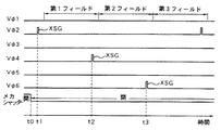
〔モニタリングモードの第2具体例〕
次に、モニタリングモード設定時の第2具体例の動作について、図9のタイミングチャートに基づいて説明する。メカシャッター24を連続して開いた状態において、第2具体例では、全画素モードの場合と同様に、第1,第2,第3フィールドの画素情報を順に読み出す構成を採っている。
【0046】
すなわち、時刻t1で2相目の垂直転送クロックVφ2に読み出しパルスXSGを立てる。すると、図7の画素配列において、例えば上から第1行目、第4行目、第7行目、……の各画素の信号電荷▲1▼,▲4▼,▲7▼,……が垂直CCD12に読み出される。これらの画素情報▲1▼,▲4▼,▲7▼,……は、第1フィールドの画素情報として、垂直転送および水平転送された後、信号電圧に変換されて信号処理回路25に供給され、切換えスイッチ35を通してフィールドメモリ31に順次格納される。
【0047】
このフィールドメモリ31に格納された第1フィールドの画素情報、即ち図7の画素配列における第1行目,第4行目,第7行目、……の各画素情報▲1▼,▲4▼,▲7▼,……は、その格納順に選択スイッチ36を通して順次読み出され、色信号処理回路37で所定の色信号処理が行われた後、画像表示装置27に供給されてモニターに映し出される。
【0048】
次いで、時刻t2で4相目の垂直転送クロックVφ4に読み出しパルスXSGを立てる。すると、図7の画素配列において、第2行目、第5行目、第8行目、……の各画素の信号電荷▲2▼,▲5▼,▲8▼,……が垂直CCD12に読み出される。これらの画素情報▲2▼,▲5▼,▲8▼,……は、第2フィールドの画素情報としてフィールドメモリ32に順次格納される。
【0049】
このフィールドメモリ32に格納された第2フィールドの画素情報、即ち図7の画素配列における第2行目,第5行目,第8行目、……の各画素情報▲2▼,▲5▼,▲8▼,……は、その格納順に選択スイッチ36を通して順次読み出され、色信号処理回路37で所定の色信号処理が行われた後、画像表示装置27に供給されて第1フィールドの場合と同様にモニターに映し出される。
【0050】
続いて、時刻t3で6相目の垂直転送クロックVφ6に読み出しパルスXSGを立てる。すると、図7の画素配列において、第3行目、第6行目、第9行目、……の各画素の信号電荷▲3▼,▲6▼,▲9▼,……が垂直CCD12に読み出される。これらの画素情報▲3▼,▲6▼,▲9▼,……は、第3フィールドの画素情報としてフィールドメモリ33に順次格納される。
【0051】
このフィールドメモリ33に格納された第3フィールドの画素情報、即ち図7の画素配列における第3行目,第6行目,第9行目、……の各画素情報▲3▼,▲6▼,▲9▼,……は、その格納順に選択スイッチ36を通して順次読み出され、色信号処理回路37で所定の色信号処理が行われた後、画像表示装置27に供給されて第1,第2フィールドの場合と同様にモニターに映し出される。
【0052】
以上の一連の制御により、第1,第2,第3フィールドの3フィールドで1フレームが構成され、各フィールドでは垂直3画素に2画素を間引く垂直間引き読み出しが行われるため、第1具体例の場合と同様に、垂直間引き読み出しを行わない場合に比べて3倍のフレームレートを実現できる。特に、各フィールドにおける信号電荷の読み出し、転送などの駆動が、全画素モードの場合と同じであるため、撮像モードに応じてクロックのタイミングなどを変える必要がない。
【0053】
また、第1,第2,第3フィールドの画素情報を順に読み出すようにしたことにより、同じフィールドの画素情報のみを繰り返して読み出すようにした第1具体例の場合に比べて、各画素における信号電荷の蓄積時間(露光時間)が3倍になるため、第1具体例の場合よりも感度を向上できるとともに、モニタリングモードにおいて、隣接する画素の信号電荷を加算しなくても全画素モードと同等の感度を得ることができる。
【0054】
上述したように、垂直2繰り返しの原色ベイヤー配列のカラーフィルタ19を具備するCCDイメージャ10を撮像デバイスとして用いたカメラシステムにおいて、3:1のインターレースを行って1フレームを3フィールドで構成し、6相の垂直転送クロックVφ1〜Vφ6で信号電荷の垂直転送を行うようにしたことにより、全画素モードとモニタリングモードで駆動系におけるクロックのタイミングなどを変えなくて良いため、駆動系の構成を簡略化できる。
【0055】
また、全画素モードだけでなく、モニタリングモードにおいても、各フィールド共、ベイヤー配列の画素情報を得ることができるため、高画質の動画を映し出すことができ、しかも信号処理系を共用化できるため、信号処理系の構成の簡略化も図れる。
【0056】
さらに、垂直CCD12を6相駆動としたことにより、垂直CCD12の取り扱い電荷量が増加するため、ダイナミックレンジを大きくとれることにもなる。すなわち、第1フィールドの信号電荷の読み出しの場合を例に採って考えると、第1フィールドでは、6相の垂直転送クロックVφ1〜Vφ6が図10に示すタイミング関係にある。すなわち、6相の垂直転送クロックVφ1〜Vφ6の内、連続する4つのクロックが常に“H”レベルの状態にある。
【0057】
例えば、2相目の垂直転送クロックVφ2に読み出しパルスXSGが立った直後、即ち信号電荷の読み出し直後では、1相目,6相目の垂直転送クロックVφ1,Vφ6が“L”レベル、それ以外が“H”レベルにある。したがって、図11のポテンシャル図に示すように、垂直転送クロックVφ2〜Vφ5に対応する連続する4転送段分のパケットPに信号電荷が蓄えられることになるため、垂直CCD12の取り扱い電荷量を増加できるのである。
【0058】
これを全画素モードおよびモニタリングモードにおける通常モードとした場合に、垂直CCD12に直接に光が混入したり、半導体基板内部で発生した電荷が拡散によって拡がって垂直CCD12に混入することによって発生するスミア成分を低減する低スミアモードを実現することも可能である。以下に、この低スミアモードでの動作について説明する。
【0059】
この低スミアモードを実現するには、先ず、図12に示すCCDイメージャにおいて、水平CCD15′の転送段を水平画素数に対して倍密度とした構成を採るとともに、6相の垂直転送クロックVφ1〜Vφ6を、図13に示すタイミング関係とする。すなわち、6相の垂直転送クロックVφ1〜Vφ6に対応する6つの転送段がポテンシャルの浅い転送段によって常に2つのパケットに分離されるようにする。
【0060】
例えば、2相目の垂直転送クロックVφ2に読み出しパルスXSGが立った直後の期間T0では、1相目,4相目の垂直転送パルスVφ1,Vφ4が“L”レベル、それ以外が“H”レベルにある。したがって、図14のポテンシャル図に示すように、2相目,3相目の垂直転送クロックVφ2,Vφ3に対応する2転送段分のパケットP1と、5相目,6相目の垂直転送クロックVφ5,Vφ6に対応する2転送段分のパケットP2とが、4相目の垂直転送パルスVφ4に対応するポテンシャルの浅い転送段によって分離される。
【0061】
これら2つのパケットP1,P2には、原理的に、同じ量のスミア成分が発生しているものと考えることができる。そして、2相目の垂直転送クロックVφ2に読み出しパルスXSGが立つことで、画素からパケットP1に対して信号電荷が読み出される。これにより、パケットP1には信号成分+スミア成分の電荷が蓄積され、パケットP2にはスミア成分のみの電荷が蓄積される。その結果、垂直CCD12上には、その転送方向において信号成分+スミア成分の電荷とスミア成分のみの電荷とが交互に存在することになる。
【0062】
そして、垂直CCD12の転送動作により、例えばスミア成分のみの電荷が1ライン分水平CCD15′にラインシフトされる。このとき、水平CCD15′の転送段が水平画素数に対して倍密度となっていることから、垂直CCD12からラインシフトされたスミア成分のみの電荷は、水平CCD15′において1パケット(1転送段)おきに存在する。このラインシフト後、水平CCD15′を1ビット(1パケット分)シフトする。
【0063】
その後、次の1ライン分の電荷、即ち信号成分+スミア成分の電荷が、垂直CCD12から水平CCD15′へラインシフトされる。このとき、水平CCD15′では1ビットシフトが行われた後であることから、信号成分+スミア成分の電荷は、スミア成分のみの電荷が存在するパケット間の空きパケットに蓄積される。これにより、水平CCD15′上には、スミア成分のみの電荷と信号成分+スミア成分の電荷とが交互に存在することになる。
【0064】
これらの電荷は、水平CCD15′によって順次水平転送され、電荷検出部16で信号電圧に変換された後、図4に示す信号処理回路25に供給される。この例の場合には、信号処理回路25は、図15に示すように、1ビット相当の遅延時間を持つ1ビット遅延回路41および引き算器42を有し、引き算器42において信号成分+スミア成分の電荷に基づく信号から、1ビット遅延回路41を経たスミア成分の電荷のみに基づく信号を引き算する処理を行うことで、スミア成分をキャンセルでき、スミアのない信号成分を得ることができる。
【0065】
なお、本例では、転送段が水平画素数に対して倍密度の水平CCD15′を用いる構成としたが、図16に示すように、転送段が水平画素数と同じ密度の2本の水平CCD15-1,15-2を並置した構成を採ることによっても低スミアモードを実現することができる。すなわち、2本の水平CCD15-1,15-2を並置するとともに、これら水平CCD15-1,15-2間に水平CCD15-1から水平CCD15-2へ信号電荷を適宜転送するHHゲート43を配置した構成が採られる。
【0066】
そして、この構成において、垂直CCD12から水平CCD15-1,15-2への電荷転送の際に、例えばスミア成分のみの電荷が1ライン分水平CCD15-1にラインシフトされ、さらにHHゲート43を通して水平CCD15-2に転送される。続いて、次の1ライン分の電荷、即ち信号成分+スミア成分の電荷が、垂直CCD12から水平CCD15-1へラインシフトされる。これにより、水平CCD15-1上には信号成分+スミア成分の電荷が存在し、水平CCD15-2上にはスミア成分のみの電荷が存在することになる。
【0067】
その後、水平CCD15-1,15-2が同期して転送駆動されることにより、水平CCD15-1,15-2の各電荷が並行して水平転送され、電荷検出部16-1,16-2で信号電圧に変換された後、図4に示す信号処理回路25に供給される。この例の場合には、信号処理回路25は、図17に示すように、引き算器44を有し、この引き算器44において信号成分+スミア成分の電荷に基づく信号からスミア成分の電荷のみのに基づく信号を引き算する処理を行うことで、スミア成分をキャンセルでき、スミアのない信号成分を得ることができる。
【0068】
図18は、本発明の第2実施形態に係る例えばIT方式のカラーCCDイメージャを示す概略構成図である。
【0069】
図18において、センサ部(画素)51が2次元マトリクス状に配列され、これらセンサ部51の垂直列ごとに複数本の垂直CCD52が配されるとともに、これら垂直CCD52と各センサ部51との間には読み出しゲート部53が介在し、さらに複数本の垂直CCD52の各転送先側の端部に隣接して水平CCD55が設けられるとともに、その端部には例えばフローティングディフュージョンアンプ構成の電荷検出部56が配された基本的な構成は、第1実施形態に係るCCDイメージャ10の場合と同じである。
【0070】
ただし、本実施形態に係るCCDイメージャ50は、垂直CCD52が3相の垂直転送クロックVφ1〜Vφ3によって3相駆動される構成となっている。この3相の垂直転送クロックVφ1〜Vφ3および水平CCD55を駆動する2相の水平転送クロックHφ1,Hφ2などは、タイミングジェネレータ(TG)57で生成される。このCCDイメージャ50においても、例えば図3に示す原色ベイヤー配列のカラーフィルタが搭載されている。
【0071】
図19は、1つのセンサ部51、それに対応する垂直CCD52の転送段および読み出しゲート部53からなるユニットセル54の構造の第1具体例を示す平面パターン図である。
【0072】
図19において、垂直CCD52の転送チャネル61の上方には、3相の垂直転送クロックVφ1〜Vφ3がそれぞれ与えられる転送電極62-1〜62-3が、1画素につき1電極の割合で垂直転送方向において順に繰り返して配置されている。これらの転送電極62-1〜62-3は、1層目のポリシリコン(図中、一点鎖線で示す)と2層目のポリシリコン(図中、二点鎖線で示す)によって交互に形成されている。なお、図中、ハッチングで示す領域はチャネルストップ部63である。
【0073】
上記構成の第2実施形態に係るCCDイメージャ50においても、垂直2繰り返しのカラーコーディングに対して垂直CCD52が3相駆動であり、先述した駆動条件を満足することから、3:1のインターレースを行うことによって1フレームを3フィールドで構成することにより、6相駆動の場合と同様にして、全画素モードとモニタリングモードを実現することができる。
【0074】
さらに、第2実施形態に係るCCDイメージャ50において、ユニットセルの第1具体例では、各画素が1つの転送電極で構成されるユニットセル構造としたことにより、各画素が2つの転送電極で構成される6相駆動の場合よりも、セル構造が簡単になるため、デバイスの微細化に有利となる。
【0075】
図20は、ユニットセル構造の第2具体例を示す平面パターン図である。図20において、垂直CCD52の転送チャネル64の上方には、3相の垂直転送クロックVφ1〜Vφ3がそれぞれ与えられる転送電極65-1〜65-3が、1画素につき1電極の割合で垂直転送方向において順に繰り返して配置され、これらの転送電極65-1〜65-3は1層のポリシリコンによって順に形成されている。なお、図中、ハッチングで示す領域はチャネルストップ部66である。
【0076】
このように、ユニットセルの第2具体例では、1画素につき1電極の割合で配される転送電極65-1〜65-3を1層のポリシリコンによって形成したことにより、第1具体例の場合と同様の効果が得られることに加え、第1具体例の場合に比べて電極形成に際しての工程数を削減できる利点がある。
【0077】
なお、上記各実施形態においては、カラーフィルタとして、原色ベイヤー配列のものを用いた場合について説明したが、カラーコーディングは原色ベイヤー配列に限られるものではなく、例えば補色ベイヤー配列であっても良い。要は、行(垂直)方向において同一の色がn繰り返し(nは2以上の整数)のものであれば、(n+1):1のインターレースを行うことにより1フレームを(n+1)フィールドにより構成するとともに、(n+1)×m相(mは自然数)のクロックによって信号電荷の垂直転送を行うことにより、全画素モードとモニタリングモードを実現できることになる。
【0078】
【発明の効果】
以上説明したように、本発明によれば、行列状に配置された画素に対して行方向において同じ色がn画素ごとに繰り返して配列されたカラーコーディングのカラーフィルタを備えた固体撮像装置において、(n+1):1のインターレースを行って1フレームを(n+1)フィールドで構成し、(n+1)×m相のクロックによって信号電荷の垂直転送を行うようにしたことにより、全画素モードとモニタリングモードで駆動系におけるクロックのタイミングなどを変えなくて良いため駆動系の構成を簡略化でき、また全画素モードだけでなく、モニタリングモードにおいても、各フィルタ共ベイヤー配列の画素情報を得ることができるため高画質の動画を映し出すことができ、しかも信号処理系を共用化できるため信号処理系の構成の簡略化も図れることになる。
【図面の簡単な説明】
【図1】本発明の第1実施形態に係るIT方式のカラーCCDイメージャを示す概略構成図である。
【図2】第1実施形態に係るユニットセル構造の一例を示す平面パターン図である。
【図3】2×2繰り返しの原色ベイヤー配列を示す図である。
【図4】本発明に係るカメラシステムを示す概略構成図である。
【図5】信号処理回路の具体的な構成の一例を示すブロック図である。
【図6】全画素モードの動作説明のためのタイミングチャートである。
【図7】画素情報の読み出し手順を示す概念図である。
【図8】モニタリングモードの第1具体例の動作説明のためのタイミングチャートである。
【図9】モニタリングモードの第2具体例の動作説明のためのタイミングチャートである。
【図10】通常モードでの6相の垂直転送クロックVφ1〜Vφ6のタイミングチャートである。
【図11】通常モードでの垂直CCDの各転送段のポテンシャル図である。
【図12】低スミアモード対応のCCDイメージャの一例を示す概略構成図である。
【図13】低スミアモードでの6相の垂直転送クロックVφ1〜Vφ6のタイミングチャートである。
【図14】低スミアモードでの垂直CCDの各転送段のポテンシャル図である。
【図15】低スミアモード対応の信号処理回路の構成の一例を示すブロック図である。
【図16】低スミアモード対応のCCDイメージャの他の例を示す概略構成図である。
【図17】低スミアモード対応の信号処理回路の構成の他の例を示すブロック図である。
【図18】本発明の第2実施形態に係るIT方式のカラーCCDイメージャを示す概略構成図である。
【図19】第2実施形態に係るユニットセル構造の一例を示す平面パターン図である。
【図20】第2実施形態に係るユニットセル構造の他の例を示す平面パターン図である。
【符号の説明】
10,50…カラーCCDイメージャ、11,51…センサ部、12,52…垂直CCD、14,54…ユニットセル、15,15′,15-1,15-2,55…水平CCD、16,16-1,16-2,56…電荷検出部、17,57…タイミングジェネレータ、19…カラーフィルタ、24…メカシャッター、25…信号処理回路、26…画像記録装置、27…画像表示装置、28…タイミングコントローラ、29…モード設定部[0001]
BACKGROUND OF THE INVENTION
The present invention relates to a solid-state imaging device, a driving method thereof, and a camera system, and more particularly to a solid-state imaging device capable of obtaining both a still image and a moving image, a driving method thereof, and a camera system using the solid-state imaging device as an imaging device. .
[0002]
[Prior art]
In a still image imaging technique represented by a still camera, a solid-state imaging device such as an IT (interline transfer) type CCD (Charge Coupled Device) imager is used as an imaging device, and a mechanical shutter (hereinafter abbreviated as a mechanical shutter). There is known a method of forming a still image by performing frame readout by using and combining pixel information for two fields in a signal processing system. In order to increase the resolution, a CCD imager having a larger number of pixels is used.
[0003]
On the other hand, when monitoring a subject, a monitoring mode (moving image mode) for displaying a moving image on a monitor is set. However, in the output part of the CCD imager, since there is a constraint between the cutoff frequency of the source follower constituting the output part and the CCD drive frequency, the output part cannot be made very fast, so the CCD imager has a large number of pixels. As the number of pixels increases, the frame rate in the monitoring mode decreases.
[0004]
By the way, in auto focus and auto iris, a frame rate of 30 frames / second is required. On the other hand, for example, in a 2 million pixel CCD imager, the frame rate is about 5 frames / second. For this reason, in a camera system using a CCD imager with 2 million pixels, when the monitoring mode is set, a frame rate of 30 frames / second is realized by performing so-called thinning-out reading driving that reads out pixel information by thinning out. I have to.
[0005]
[Problems to be solved by the invention]
However, as described above, in the conventional technique in which frame readout driving is performed in the all-pixel mode (still image mode) for obtaining a still image while thinning readout driving is performed in the monitoring mode, signal charge is read and transferred. Because the driving for the difference between the all-pixel mode and the monitoring mode, there is a problem that the configuration of the driving system including the clock becomes complicated.
[0006]
In the monitoring mode, since the exposure time is shorter than that in the all-pixel mode, the sensitivity is lowered accordingly. The decrease in sensitivity due to the shortening of the exposure time can be suppressed by adding the signal charges of adjacent pixels. However, in the color CCD imager, in the case of color coding in which adjacent colors are different as in the Bayer array, signals of adjacent pixels cannot be added to each other. Therefore, the sensitivity associated with shortening the exposure time in the monitoring mode. However, there is a problem that the sensitivity in the monitoring mode is lower than the sensitivity in the all-pixel mode.
[0007]
The present invention has been made in view of the above problems, and an object of the present invention is to provide a solid-state imaging device capable of sharing a driving system in all pixel mode and monitoring mode, a driving method thereof, and imaging the solid-state imaging device. It is to provide a camera system used as a device.
[0008]
[Means for Solving the Problems]
A solid-state imaging device according to the present invention includes a color coding color filter in which the same color is repeatedly arranged every n pixels (n is an integer of 2 or more) in a row direction with respect to pixels arranged in a matrix, and (n + 1) ): 1 interlaced, 1 frame is composed of (n + 1) fields, and a drive system that performs vertical transfer of signal charges with a clock of (n + 1) × m phase (m is a natural number). Yes.
[0009]
The solid-state imaging device driving method according to the present invention includes a color coding color filter in which the same color is repeatedly arranged in every n pixels in the row direction with respect to pixels arranged in a matrix. n + 1): 1 interlace is performed to form one frame with (n + 1) fields, and signal charges are vertically transferred by a clock of (n + 1) × m phases.
[0010]
The camera system according to the present invention uses the solid-state imaging device having the above configuration as an imaging device, and includes a mode setting unit that selectively sets the all-pixel mode and the monitoring mode. The timing controller controls the timing of the solid-state imaging device and the opening / closing control of the mechanical shutter according to the imaging mode set by the mode setting unit, while the image based on the signal processed by the signal processing circuit when the all-pixel mode is set. Information is recorded on the recording medium as still image information, and a moving image based on the signal processed by the signal processing circuit is displayed on the monitor when the monitoring mode is set.
[0011]
DETAILED DESCRIPTION OF THE INVENTION
Hereinafter, embodiments of the present invention will be described in detail with reference to the drawings. FIG. 1 is a schematic configuration diagram showing, for example, an IT type color CCD imager according to a first embodiment of the present invention.
[0012]
In FIG. 1, a large number of sensor units (pixels) 11 that convert incident light into signal charges having a charge amount corresponding to the amount of light and store the same are arranged in a two-dimensional matrix in the vertical (row) direction and horizontal (column) direction. Has been. Further, a plurality of vertical CCDs 12 are provided for each vertical row of the
[0013]
The signal charges accumulated in the plurality of
[0014]
In the six-phase drive vertical CCD 12, for example, the transfer electrodes to which the second-phase, fourth-phase and sixth-phase vertical
[0015]
FIG. 2 is a plan pattern diagram showing a specific structure of the unit cell 14. In FIG. 2, transfer electrodes 22-1 to 22-6 to which 6-phase vertical transfer clocks Vφ1 to Vφ6 are respectively applied are overlapped on the side of the
[0016]
In FIG. 1 again, the
[0017]
At the end of the
[0018]
Various timing pulses such as the six-phase vertical transfer clocks Vφ1 to Vφ6 including the read pulse XSG for transferring and driving the vertical CCD 12 and the two-phase horizontal transfer clocks Hφ1 and Hφ2 for transferring and driving the
[0019]
Thus, the IT-
[0020]
FIG. 4 is a schematic configuration diagram showing a camera system according to the present invention using the
[0021]
In FIG. 4, the camera system includes a
[0022]
In the camera system configured as described above, incident light (image light) from the subject is imaged on the imaging surface of the
[0023]
The
[0024]
Therefore, 6-phase (= 3 fields × 2) vertical transfer clocks Vφ1 to Vφ6 are generated, and the vertical CCD 12 is driven in 6 phases. However, it is not limited to 6-phase driving, and 3-phase (= 3 fields × 1) driving or 9-phase (= 3 fields × 3) driving may be used. The case of three-phase driving will be described later in detail.
[0025]
In this example, color coding of the color filter 19 is repeated twice in the vertical direction, and 3: 1 interlace is performed on this, so that one frame is composed of 3 (= 2 + 1) fields and the transfer drive of the vertical CCD 12 is performed. Is performed with a 3 × m (m is a natural number) phase clock. In short, one frame is obtained by performing (n + 1): 1 interlace for vertical n repetitions (n is an integer of 2 or more). Any configuration may be used as long as it is configured with (n + 1) fields and the transfer drive of the vertical CCD 12 is performed with a clock of (n + 1) × m phases.
[0026]
For example, as shown in FIG. 5, the
[0027]
In the
[0028]
The
[0029]
The number of vertical scanning lines of the monitor used in the monitoring mode is set to 1/3 of the number of rows (number of vertical scanning lines) of the
[0030]
Next, in the camera system having the above configuration, each operation when the all pixel mode is set by the
[0031]
[All pixel mode]
First, the operation when the all-pixel mode is set will be described with reference to the timing chart of FIG. 6. The
[0032]
These pixel information {circle over (1)}, {circle over (4)}, {7},... Are vertically transferred by the vertical CCD 12 and further horizontally transferred by the
[0033]
Next, at time t2, the read pulse XSG is raised only for the fourth-phase vertical transfer clock Vφ4. Then, in the pixel array of FIG. 7, the signal charges (2), (5), (8),... Of the pixels in the second row, the fifth row, the eighth row,. Read out. These pixel information (2), (5), (8),... Are vertically and horizontally transferred as pixel information of the second field, converted to a signal voltage, and supplied to the
[0034]
Subsequently, at time t3, the read pulse XSG is raised only for the vertical transfer clock Vφ6 of the sixth phase. Then, in the pixel array of FIG. 7, the signal charges (3), (6), (9),... Of the pixels in the third row, the sixth row, the ninth row,. Read out. These pieces of pixel information are {3}, {6}, {9},..., And are transferred to the
[0035]
After the pixel information for three fields is stored in the
[0036]
With the series of controls described above, one frame (one screen) is configured by three fields, and the read pixel information corresponds to the pixel arrangement in FIG. Thereby, the pixel information of all the pixels of the
[0037]
In this all-pixel mode, in each field, vertical thinning readout is performed in which two pixels are thinned out every three vertical pixels. After the pixel information of each field is stored in the
[0038]
[First example of monitoring mode]
Next, the operation of the first specific example when the monitoring mode is set will be described based on the timing chart of FIG. In the monitoring mode, since a moving image is obtained, the
[0039]
That is, the read pulse XSG is raised only at the second phase vertical transfer clock Vφ2 at time t1. Then, in the pixel array of FIG. 7, for example, the signal charges (1), (4), (7),... Of the pixels in the first row, the fourth row, the seventh row,. Read to the vertical CCD 12. These pixel information (1), (4), (7),... Are vertically transferred and horizontally transferred as pixel information of the first field, converted to a signal voltage, and supplied to the
[0040]
The pixel information of the first field stored in the
[0041]
Next, at time t2, the read pulse XSG is set again only for the vertical transfer clock Vφ2 of the second phase. Then, as in the previous case, the pixel information of the first field, that is, the signal charges (1), (4), (7) of the pixels of the first row, the fourth row, the seventh row,. Are read out and sequentially stored in the
[0042]
Subsequently, at time t3, the read pulse XSG is set again only for the vertical transfer clock Vφ2 of the second phase. Then, the signal charges (1), (4), (7),... Of the pixels in the first row, the fourth row, the seventh row,. Are sequentially stored in the
[0043]
Through the above-described series of controls, vertical thinning-out reading is performed by thinning out two pixels into three vertical pixels by repeatedly reading out only the first field, so that the frame rate is three times that of the case where vertical thinning-out reading is not performed. it can. In particular, since driving for reading and transferring signal charges in each field is the same as in the all-pixel mode, there is no need to change the clock timing or the like according to the imaging mode.
[0044]
In the first specific example, only the pixel information (1), (4), (7),... Of the first field is repeatedly read, but the pixel information (2), (5) of the second field is read. Of course, it is possible to repeatedly read out only the pixel information (3), (6), (9),...
[0045]
[Second specific example of monitoring mode]
Next, the operation of the second specific example when the monitoring mode is set will be described based on the timing chart of FIG. In the state where the
[0046]
That is, the read pulse XSG is raised at the second phase vertical transfer clock Vφ2 at time t1. Then, in the pixel array of FIG. 7, for example, the signal charges (1), (4), (7),... Of the pixels in the first row, the fourth row, the seventh row,. Read to the vertical CCD 12. These pixel information (1), (4), (7),... Are vertically transferred and horizontally transferred as pixel information of the first field, converted to a signal voltage, and supplied to the
[0047]
The pixel information of the first field stored in the
[0048]
Next, at time t2, a read pulse XSG is set on the fourth-phase vertical transfer clock Vφ4. Then, in the pixel array of FIG. 7, the signal charges (2), (5), (8),... Of the pixels in the second row, the fifth row, the eighth row,. Read out. These pixel information (2), (5), (8),... Are sequentially stored in the
[0049]
The pixel information of the second field stored in the
[0050]
Subsequently, at time t3, a read pulse XSG is set on the sixth-phase vertical transfer clock Vφ6. Then, in the pixel array of FIG. 7, the signal charges (3), (6), (9),... Of the pixels in the third row, the sixth row, the ninth row,. Read out. These pixel information (3), (6), (9),... Are sequentially stored in the
[0051]
The pixel information of the third field stored in the
[0052]
With the series of controls described above, one frame is composed of three fields of the first, second, and third fields. In each field, vertical thinning readout is performed in which two pixels are thinned out into three vertical pixels. As in the case, a frame rate three times that in the case where vertical thinning readout is not performed can be realized. In particular, since driving for reading and transferring signal charges in each field is the same as in the all-pixel mode, there is no need to change the clock timing or the like according to the imaging mode.
[0053]
Further, since the pixel information of the first, second, and third fields are sequentially read out, the signal in each pixel is compared with the case of the first specific example in which only the pixel information of the same field is repeatedly read out. Since the charge accumulation time (exposure time) is tripled, the sensitivity can be improved compared to the case of the first specific example, and in the monitoring mode, it is equivalent to the all pixel mode without adding the signal charges of adjacent pixels. Can be obtained.
[0054]
As described above, in the camera system using the
[0055]
In addition, not only in the all pixel mode but also in the monitoring mode, each field can obtain the pixel information of the Bayer array, so that a high-quality moving image can be displayed and the signal processing system can be shared. The configuration of the signal processing system can be simplified.
[0056]
Further, since the vertical CCD 12 is driven in six phases, the amount of charge handled by the vertical CCD 12 is increased, so that the dynamic range can be increased. That is, taking the case of reading signal charges in the first field as an example, in the first field, the six-phase vertical transfer clocks Vφ1 to Vφ6 have the timing relationship shown in FIG. That is, four consecutive clocks among the six-phase vertical transfer clocks Vφ1 to Vφ6 are always in the “H” level state.
[0057]
For example, immediately after the read pulse XSG is set on the vertical transfer clock Vφ2 of the second phase, that is, immediately after the signal charge is read out, the vertical transfer clocks Vφ1 and Vφ6 of the first phase and the sixth phase are at the “L” level. “H” level. Therefore, as shown in the potential diagram of FIG. 11, signal charges are stored in the packets P for four consecutive transfer stages corresponding to the vertical transfer clocks Vφ2 to Vφ5, so that the amount of charge handled by the vertical CCD 12 can be increased. It is.
[0058]
When this is set to the normal mode in the all-pixel mode and the monitoring mode, smear components generated when light is directly mixed into the vertical CCD 12 or charges generated inside the semiconductor substrate are spread by diffusion and mixed into the vertical CCD 12. It is also possible to realize a low smear mode that reduces the above. The operation in the low smear mode will be described below.
[0059]
In order to realize the low smear mode, first, in the CCD imager shown in FIG. 12, the transfer stage of the horizontal CCD 15 'is doubled with respect to the number of horizontal pixels, and the six-phase vertical transfer clocks V.phi. Let Vφ6 be the timing relationship shown in FIG. That is, the six transfer stages corresponding to the six-phase vertical transfer clocks Vφ1 to Vφ6 are always separated into two packets by a transfer stage having a shallow potential.
[0060]
For example, in the period T0 immediately after the read pulse XSG is raised in the second-phase vertical transfer clock Vφ2, the first-phase and fourth-phase vertical transfer pulses Vφ1 and Vφ4 are at the “L” level, and the others are at the “H” level. It is in. Therefore, as shown in the potential diagram of FIG. 14, the packet P1 for two transfer stages corresponding to the second-phase and third-phase vertical transfer clocks Vφ2 and Vφ3, and the fifth-phase and sixth-phase vertical transfer clocks Vφ5. , Vφ6 is separated from the packet P2 for two transfer stages by a transfer stage having a shallow potential corresponding to the vertical transfer pulse Vφ4 of the fourth phase.
[0061]
In principle, it can be considered that the same amount of smear component is generated in these two packets P1 and P2. The signal charge is read from the pixel to the packet P1 by setting the read pulse XSG at the vertical transfer clock Vφ2 of the second phase. Thereby, the charge of the signal component + smear component is accumulated in the packet P1, and the charge of only the smear component is accumulated in the packet P2. As a result, the charge of the signal component + smear component and the charge of only the smear component are alternately present on the vertical CCD 12 in the transfer direction.
[0062]
Then, due to the transfer operation of the vertical CCD 12, for example, the charge of only the smear component is line shifted to the horizontal CCD 15 'by one line. At this time, since the transfer stage of the horizontal CCD 15 'has a double density with respect to the number of horizontal pixels, the charge of only the smear component shifted from the vertical CCD 12 is one packet (one transfer stage) in the horizontal CCD 15'. It exists every other. After this line shift, the horizontal CCD 15 'is shifted by one bit (one packet).
[0063]
Thereafter, the charge for the next line, that is, the charge of the signal component + smear component is line-shifted from the vertical CCD 12 to the horizontal CCD 15 '. At this time, since the horizontal CCD 15 'has been shifted by 1 bit, the charge of the signal component + smear component is accumulated in an empty packet between packets in which only the charge of the smear component exists. As a result, only the smear component charge and the signal component + smear component charge exist alternately on the horizontal CCD 15 '.
[0064]
These charges are sequentially transferred horizontally by the horizontal CCD 15 ', converted into a signal voltage by the
[0065]
In this example, the transfer stage uses a horizontal CCD 15 'having a double density with respect to the number of horizontal pixels. However, as shown in FIG. 16, the transfer stage has two
[0066]
In this configuration, when charges are transferred from the vertical CCD 12 to the horizontal CCDs 15-1 and 15-2, for example, the charge of only the smear component is line-shifted to the horizontal CCD 15-1 by one line and further passed through the
[0067]
Thereafter, the horizontal CCDs 15-1 and 15-2 are synchronously driven to transfer, so that the charges of the horizontal CCDs 15-1 and 15-2 are horizontally transferred in parallel, and the charge detectors 16-1 and 16-2. Is converted to a signal voltage and supplied to the
[0068]
FIG. 18 is a schematic configuration diagram showing, for example, an IT type color CCD imager according to the second embodiment of the present invention.
[0069]
In FIG. 18, sensor units (pixels) 51 are arranged in a two-dimensional matrix, and a plurality of vertical CCDs 52 are arranged for each vertical column of the
[0070]
However, the
[0071]
FIG. 19 is a plan pattern diagram showing a first specific example of the structure of the unit cell 54 including one
[0072]
In FIG. 19, above the
[0073]
Also in the
[0074]
Furthermore, in the
[0075]
FIG. 20 is a plan pattern diagram showing a second specific example of the unit cell structure. In FIG. 20, above the transfer channel 64 of the vertical CCD 52, transfer electrodes 65-1 to 65-3 to which three-phase vertical transfer clocks Vφ1 to Vφ3 are respectively applied are in the vertical transfer direction at a rate of one electrode per pixel. The transfer electrodes 65-1 to 65-3 are sequentially formed of one layer of polysilicon. In the figure, the area indicated by hatching is the channel stop portion 66.
[0076]
As described above, in the second specific example of the unit cell, the transfer electrodes 65-1 to 65-3 arranged at a rate of one electrode per pixel are formed of one layer of polysilicon, so that the first specific example. In addition to obtaining the same effect as the case, there is an advantage that the number of steps for forming the electrode can be reduced as compared with the case of the first specific example.
[0077]
In each of the above embodiments, the case where the primary color Bayer array is used as the color filter has been described. However, the color coding is not limited to the primary color Bayer array, and may be a complementary color Bayer array, for example. In short, if the same color has n repetitions in the row (vertical) direction (n is an integer of 2 or more), (n + 1): 1 interlace is performed to constitute one frame by (n + 1) fields. At the same time, the all-pixel mode and the monitoring mode can be realized by performing the vertical transfer of the signal charges with the clock of (n + 1) × m phase (m is a natural number).
[0078]
【The invention's effect】
As described above, according to the present invention, in a solid-state imaging device including a color coding color filter in which the same color is repeatedly arranged every n pixels in the row direction with respect to pixels arranged in a matrix, (N + 1): 1 interlace is performed to form one frame with (n + 1) fields, and vertical transfer of signal charges is performed by a clock of (n + 1) × m phase, so that all pixel mode and monitoring mode are used. Since it is not necessary to change the timing of the clock in the drive system, the configuration of the drive system can be simplified, and not only in the all pixel mode but also in the monitoring mode, pixel information of the Bayer array can be obtained for each filter. The video processing system can be projected and the signal processing system can be shared, simplifying the configuration of the signal processing system It will also be reduced.
[Brief description of the drawings]
FIG. 1 is a schematic configuration diagram illustrating an IT color CCD imager according to a first embodiment of the present invention.
FIG. 2 is a plan pattern diagram showing an example of a unit cell structure according to the first embodiment.
FIG. 3 is a diagram showing a 2 × 2 repeated primary color Bayer arrangement;
FIG. 4 is a schematic configuration diagram showing a camera system according to the present invention.
FIG. 5 is a block diagram illustrating an example of a specific configuration of a signal processing circuit.
FIG. 6 is a timing chart for explaining the operation in the all-pixel mode.
FIG. 7 is a conceptual diagram illustrating a procedure for reading pixel information.
FIG. 8 is a timing chart for explaining the operation of the first specific example of the monitoring mode.
FIG. 9 is a timing chart for explaining the operation of the second specific example of the monitoring mode;
FIG. 10 is a timing chart of six-phase vertical transfer clocks Vφ1 to Vφ6 in a normal mode.
FIG. 11 is a potential diagram of each transfer stage of the vertical CCD in the normal mode.
FIG. 12 is a schematic configuration diagram showing an example of a CCD imager compatible with a low smear mode.
FIG. 13 is a timing chart of six-phase vertical transfer clocks Vφ1 to Vφ6 in the low smear mode.
FIG. 14 is a potential diagram of each transfer stage of the vertical CCD in the low smear mode.
FIG. 15 is a block diagram showing an example of a configuration of a signal processing circuit corresponding to a low smear mode.
FIG. 16 is a schematic configuration diagram showing another example of a CCD imager compatible with a low smear mode.
FIG. 17 is a block diagram showing another example of the configuration of the signal processing circuit corresponding to the low smear mode.
FIG. 18 is a schematic configuration diagram showing an IT color CCD imager according to a second embodiment of the present invention.
FIG. 19 is a plan pattern diagram showing an example of a unit cell structure according to the second embodiment.
FIG. 20 is a plan pattern diagram showing another example of the unit cell structure according to the second embodiment.
[Explanation of symbols]
DESCRIPTION OF
Claims (11)
(n+1):1のインターレースを行って1フレームを(n+1)フィールドで構成し、(n+1)×m相(mは自然数)のクロックによって信号電荷の垂直転送を行う駆動系と
を備えたことを特徴とする固体撮像装置。A color filter for color coding in which the same color is repeatedly arranged for every n pixels (n is an integer of 2 or more) in the row direction with respect to the pixels arranged in a matrix;
(N + 1): 1 interlaced, one frame is composed of (n + 1) fields, and a drive system that performs vertical transfer of signal charges with a clock of (n + 1) × m phases (m is a natural number) is provided. A solid-state imaging device.
ことを特徴とする請求項1記載の固体撮像装置。2. The solid-state imaging device according to claim 1, wherein the driving system independently transfers and drives signal component + smear component charge and smear component charge during vertical transfer.
列方向の画素数に対して倍密度の転送段を持つ水平転送部を有する
ことを特徴とする固体撮像装置。The solid-state imaging device according to claim 2,
A solid-state imaging device having a horizontal transfer unit having a transfer stage having a double density with respect to the number of pixels in the column direction.
列方向の画素数に対して同密度の転送段を持ち、かつ互いに並置された2本の水平転送部と、この2本の水平転送部間において電荷の転送を選択的に行う転送ゲートとを有する
ことを特徴とする固体撮像装置。The solid-state imaging device according to claim 2,
Two horizontal transfer units having transfer stages of the same density with respect to the number of pixels in the column direction and juxtaposed to each other, and a transfer gate for selectively transferring charges between the two horizontal transfer units A solid-state imaging device comprising:
ことを特徴とする請求項1記載の固体撮像装置。2. The solid-state imaging device according to claim 1, wherein the drive system is a three-phase drive and has a unit cell structure in which one transfer electrode is assigned to one pixel.
ことを特徴とする請求項5記載の固体撮像装置。6. The solid-state imaging device according to claim 5, wherein the transfer electrode is formed of two layers of polysilicon.
ことを特徴とする請求項5記載の固体撮像装置。6. The solid-state imaging device according to claim 5, wherein the transfer electrode is formed of a single layer of polysilicon.
(n+1):1のインターレースを行って1フレームを(n+1)フィールドて構成し、(n+1)×m相(mは自然数)のクロックによって信号電荷の垂直転送を行う
ことを特徴とする固体撮像装置の駆動方法。A driving method of a solid-state imaging device including a color coding color filter in which the same color is repeatedly arranged for every n pixels (n is an integer of 2 or more) in a row direction with respect to pixels arranged in a matrix. ,
(N + 1): 1 solid-state imaging device characterized in that one frame is formed by (n + 1) fields by performing interlace, and signal charges are vertically transferred by a clock of (n + 1) × m phases (m is a natural number). Driving method.
ことを特徴とする請求項8記載の固体撮像装置の駆動方法。9. The driving of a solid-state imaging device according to claim 8, wherein in the (n + 1) times monitoring mode, only the pixel information of any one of (n + 1) fields is repeatedly read to display a moving image. Method.
ことを特徴とする請求項8記載の固体撮像装置の駆動方法。9. The method for driving a solid-state imaging device according to claim 8, wherein in the (n + 1) times monitoring mode, the pixel information of the (n + 1) field is sequentially read to display a moving image.
被写体からの入射光を前記固体撮像装置の撮像面上に選択的に取り込むメカニカルシャッターと、
全画素モードとモニタリングモードとを選択的に設定するモード設定部と、
前記モード設定部で設定された撮像モードに応じて前記固体撮像装置のタイミング制御および前記メカニカルシャッターの開閉制御を行うタイミングコントローラと、
前記固体撮像装置の出力信号を処理する信号処理回路と、
前記信号処理回路で処理された信号に基づく画像情報を記録媒体に記録する画像記録装置と、
前記信号処理回路で処理された信号に基づく画像情報をモニターに表示する画像表示装置と
を備えたことを特徴とするカメラシステム。A color coding color filter in which the same color is repeatedly arranged for every n pixels (n is an integer of 2 or more) in the row direction with respect to pixels arranged in a matrix, and (n + 1): 1 interlace is provided. A solid-state imaging device configured to perform vertical transfer of signal charges with a clock of (n + 1) × m phase (m is a natural number),
A mechanical shutter that selectively captures incident light from a subject onto the imaging surface of the solid-state imaging device;
A mode setting section for selectively setting all pixel mode and monitoring mode;
A timing controller that performs timing control of the solid-state imaging device and opening / closing control of the mechanical shutter according to the imaging mode set by the mode setting unit;
A signal processing circuit for processing an output signal of the solid-state imaging device;
An image recording apparatus for recording image information on a recording medium based on the signal processed by the signal processing circuit;
A camera system comprising: an image display device that displays image information based on a signal processed by the signal processing circuit on a monitor.
Priority Applications (1)
| Application Number | Priority Date | Filing Date | Title |
|---|---|---|---|
| JP00155899A JP4078741B2 (en) | 1999-01-07 | 1999-01-07 | Solid-state imaging device, driving method thereof, and camera system |
Applications Claiming Priority (1)
| Application Number | Priority Date | Filing Date | Title |
|---|---|---|---|
| JP00155899A JP4078741B2 (en) | 1999-01-07 | 1999-01-07 | Solid-state imaging device, driving method thereof, and camera system |
Publications (3)
| Publication Number | Publication Date |
|---|---|
| JP2000201355A JP2000201355A (en) | 2000-07-18 |
| JP2000201355A5 JP2000201355A5 (en) | 2006-02-02 |
| JP4078741B2 true JP4078741B2 (en) | 2008-04-23 |
Family
ID=11504866
Family Applications (1)
| Application Number | Title | Priority Date | Filing Date |
|---|---|---|---|
| JP00155899A Expired - Fee Related JP4078741B2 (en) | 1999-01-07 | 1999-01-07 | Solid-state imaging device, driving method thereof, and camera system |
Country Status (1)
| Country | Link |
|---|---|
| JP (1) | JP4078741B2 (en) |
Families Citing this family (10)
| Publication number | Priority date | Publication date | Assignee | Title |
|---|---|---|---|---|
| JP2002118247A (en) * | 2000-10-11 | 2002-04-19 | Sony Corp | Solid-state image pick up element and its driving method |
| JP3854826B2 (en) | 2001-08-08 | 2006-12-06 | キヤノン株式会社 | Imaging device |
| JP4738667B2 (en) * | 2001-08-10 | 2011-08-03 | キヤノン株式会社 | Imaging device |
| JP3664123B2 (en) | 2001-10-03 | 2005-06-22 | ソニー株式会社 | Imaging apparatus and image quality correction method |
| US7471321B2 (en) | 2002-01-30 | 2008-12-30 | Ricoh Company, Ltd. | Photographing apparatus and photographing method |
| CN1269364C (en) | 2002-05-01 | 2006-08-09 | 佳能株式会社 | Photographic device, photographic method, programme and recording medium |
| JP4022152B2 (en) * | 2003-01-29 | 2007-12-12 | 株式会社リコー | Imaging device |
| JP4207736B2 (en) | 2003-10-01 | 2009-01-14 | ソニー株式会社 | Solid-state imaging device |
| JP2007006243A (en) * | 2005-06-24 | 2007-01-11 | Seiko Epson Corp | Digital camera and control method thereof |
| JP6451315B2 (en) * | 2014-12-26 | 2019-01-16 | 株式会社シグマ | Imaging device |
-
1999
- 1999-01-07 JP JP00155899A patent/JP4078741B2/en not_active Expired - Fee Related
Also Published As
| Publication number | Publication date |
|---|---|
| JP2000201355A (en) | 2000-07-18 |
Similar Documents
| Publication | Publication Date | Title |
|---|---|---|
| JP3511772B2 (en) | Solid-state imaging device, driving method of solid-state imaging device, camera device and camera system | |
| US7002630B1 (en) | Method of driving solid-state imaging device, solid-state imaging device and camera | |
| JPH0416949B2 (en) | ||
| JP2894341B1 (en) | Driving method of solid-state imaging device | |
| JP2007295230A (en) | Solid state imaging apparatus, driving method thereof, and camera | |
| JP4078741B2 (en) | Solid-state imaging device, driving method thereof, and camera system | |
| JP3950655B2 (en) | Imaging device | |
| JPH08242410A (en) | Electronic camera that creates interlaced image from sequential scanning sensor of electronic camera | |
| JP3459738B2 (en) | Imaging device | |
| US20050280726A1 (en) | Image sensor for still or video photography | |
| JP2004112768A (en) | Image pickup device | |
| JPH0414554B2 (en) | ||
| JPH11146408A (en) | Solid-state image pickup device and method for charge read-out for the same | |
| JP3985275B2 (en) | Imaging apparatus and imaging method | |
| JP4069533B2 (en) | Solid-state imaging device, driving method thereof, and camera system | |
| JP5045183B2 (en) | Solid-state image sensor, solid-state image sensor driving method, and camera system | |
| JP4022682B2 (en) | Imaging apparatus and image output method | |
| JP3878769B2 (en) | Driving method of solid-state imaging device | |
| JP4112106B2 (en) | Imaging device | |
| JP2000115643A (en) | Drive method for solid-state image pickup device, the solid-state image pickup device, solid-state image pickup element and image pickup camera | |
| JP2966740B2 (en) | Solid-state imaging device and driving method thereof | |
| JP4745676B2 (en) | Imaging device | |
| JP2001145025A (en) | Solid-state image pickup device and its drive method | |
| JP3392607B2 (en) | Driving method of solid-state imaging device | |
| JPH0591416A (en) | Solid-state image pickup device and its driving method |
Legal Events
| Date | Code | Title | Description |
|---|---|---|---|
| A521 | Request for written amendment filed |
Free format text: JAPANESE INTERMEDIATE CODE: A523 Effective date: 20051208 |
|
| A621 | Written request for application examination |
Free format text: JAPANESE INTERMEDIATE CODE: A621 Effective date: 20051208 |
|
| A977 | Report on retrieval |
Free format text: JAPANESE INTERMEDIATE CODE: A971007 Effective date: 20071214 |
|
| TRDD | Decision of grant or rejection written | ||
| A01 | Written decision to grant a patent or to grant a registration (utility model) |
Free format text: JAPANESE INTERMEDIATE CODE: A01 Effective date: 20080115 |
|
| A61 | First payment of annual fees (during grant procedure) |
Free format text: JAPANESE INTERMEDIATE CODE: A61 Effective date: 20080128 |
|
| FPAY | Renewal fee payment (event date is renewal date of database) |
Free format text: PAYMENT UNTIL: 20110215 Year of fee payment: 3 |
|
| FPAY | Renewal fee payment (event date is renewal date of database) |
Free format text: PAYMENT UNTIL: 20110215 Year of fee payment: 3 |
|
| FPAY | Renewal fee payment (event date is renewal date of database) |
Free format text: PAYMENT UNTIL: 20120215 Year of fee payment: 4 |
|
| FPAY | Renewal fee payment (event date is renewal date of database) |
Free format text: PAYMENT UNTIL: 20130215 Year of fee payment: 5 |
|
| LAPS | Cancellation because of no payment of annual fees |