JP4075771B2 - Estimation device, automatic musical instrument and program - Google Patents
Estimation device, automatic musical instrument and program Download PDFInfo
- Publication number
- JP4075771B2 JP4075771B2 JP2003374315A JP2003374315A JP4075771B2 JP 4075771 B2 JP4075771 B2 JP 4075771B2 JP 2003374315 A JP2003374315 A JP 2003374315A JP 2003374315 A JP2003374315 A JP 2003374315A JP 4075771 B2 JP4075771 B2 JP 4075771B2
- Authority
- JP
- Japan
- Prior art keywords
- value
- sample
- weighting factor
- key
- sigma
- Prior art date
- Legal status (The legal status is an assumption and is not a legal conclusion. Google has not performed a legal analysis and makes no representation as to the accuracy of the status listed.)
- Expired - Fee Related
Links
Images


Classifications
-
- G—PHYSICS
- G10—MUSICAL INSTRUMENTS; ACOUSTICS
- G10F—AUTOMATIC MUSICAL INSTRUMENTS
- G10F1/00—Automatic musical instruments
- G10F1/02—Pianofortes with keyboard
Landscapes
- Physics & Mathematics (AREA)
- Engineering & Computer Science (AREA)
- Acoustics & Sound (AREA)
- Multimedia (AREA)
- Electrophonic Musical Instruments (AREA)
Description
この発明は、信号成分以外の雑音を発生する機器に用いて好適な推定装置、自動楽器およびプログラムに関する。
The present invention relates to an estimation device, an automatic musical instrument, and a program suitable for use in equipment that generates noise other than signal components.
従来の自動演奏ピアノにおいては、各鍵を駆動するソレノイドと、各鍵の押下深さを計測するキーセンサとが設けられている。自動演奏ピアノに対して、押鍵イベント、打弦イベント等から成る演奏情報が供給されると、該演奏情報に基づいて各鍵のリファレンス軌道(鍵軌道の目標値)が生成され、各押鍵深さは上記キーセンサの検出信号に基づいて、リファレンス軌道に沿うようにサーボ制御される。なお、かかる技術は、例えば特許文献1に開示されている。
ところで、一般的な機械装置と比較すると自動演奏ピアノには、木材、フェルト、布などアンリジッドな部品が多用されている。また、部品同士の結合部分にも遊びが多いため、センサの検出値には必然的に雑音が混入する。
この発明は上述した事情に鑑みてなされたものであり、直近のサンプリング値の正確な推測値を少ない演算量で得る推定装置、自動楽器およびプログラムを提供することを目的としている。
By the way, compared with a general mechanical device, unsteady parts such as wood, felt, and cloth are often used in an automatic performance piano. In addition, since there is a lot of play in the joint portion between the parts, noise is inevitably mixed in the detection value of the sensor.
The present invention has been made in view of the above-described circumstances, and an object thereof is to provide an estimation device, an automatic musical instrument, and a program for obtaining an accurate estimated value of the latest sampling value with a small amount of calculation.
上記課題を解決するため本発明にあっては、下記構成を具備することを特徴とする。なお、括弧内は例示である。
請求項1記載の推定装置にあっては、移動物体(70)の位置または速度を推定する推定装置であって、前記移動物体(70)の位置を測定するセンサ(25)と、前記センサからの情報を定期的にサンプリングするサンプリング手段(SP4,SP6)と、該サンプリング手段でサンプリングされたサンプル値を、予め定めた所定サンプル数記憶する第1の記憶手段(RAM54,位置記憶レジスタy0〜y6)と、前記所定サンプル数によって決定される重み係数であって、前記位置の近似値を求める位置近似多項式(yj=a*tj 2 +b*tj+c)における該位置の近似値(yj)と複数の前記サンプル値(xj)との自乗誤差(E=SIGMA(xj-yj) 2 )を最小にする、前記位置近似多項式の係数(a,b,c)に基づいて定められた(wXjについては、段落0012〜0015、wVjについては段落0009〜0011)重み係数(wXj,wVj)を記憶する第2の記憶手段(フラッシュROM52)と、該第2の記憶手段から前記重み係数を読み出す読出し手段(CPU50,段落0045〜0046)と、前記サンプル値と前記重み係数とを乗算し、これらの乗算結果を加算することによって前記移動物体のサンプル点終端の位置または速度を推定する演算手段(CPU50,段落0045〜0046)とを具備することを特徴とする。
また、請求項2記載の自動楽器にあっては、駆動されることによって楽音を発生させる複数の操作子(70)と、前記各操作子(70)毎に設けられ、供給された駆動信号に応じてこれら操作子を駆動する複数のアクチュエータ(10)と、前記各操作子毎に設けられ、これら操作子の変位を測定し、該測定された変位を表す検出信号を出力する複数のセンサ(25)と、供給された演奏情報に従って、前記各操作子の軌道リファランスを決定する軌道リファランス決定手段(110)と、各々の前記操作子(70)について、複数回に渡る前記検出信号のサンプル値(位置記憶レジスタy0〜y6)と該サンプル値の数によって決定される所定の重み係数(wVj,wXj)との積の加算結果を計算することによって、サンプル点終端における位置または速度の推測値である終端推測値(X,V)を決定する終端推測値決定手段(120)であって、前記重み係数(wVj,wXj)は、前記変位の近似値を求める変位近似多項式(yj=a*tj 2 +b*tj+c)における該変位の近似値(yj)と複数の前記サンプル値(xj)との自乗誤差(E=SIGMA(xj-yj) 2 )を最小にする、前記変位近似多項式の係数(a,b,c)に基づいて定められた(wXjについては、段落0012〜0015、wVjについては段落0009〜0011)重み係数(wVj,wXj)である、終端推測値決定手段(120)と、逐次計算される前記終端推測値が、前記軌道リファランスに基づく目標値に近づくように前記駆動信号を出力する駆動信号出力手段(120,30)とを具備することを特徴とする。
また、請求項3記載のプログラムにあっては、処理装置(50)を有し、移動物体(70)の位置を測定するセンサ(25)からの情報に基づいて該移動物体(70)の位置または速度を推定する推定装置に適用されるプログラムであって、前記センサからの情報を定期的にサンプリングするサンプリング過程(SP4,SP6)と、該サンプリング過程でサンプリングされたサンプル値を、予め定めた所定サンプル数だけ第1の記憶手段(RAM54,位置記憶レジスタy0〜y6)に記憶する過程と、前記所定サンプル数によって決定される重み係数であって、前記位置の近似値を求める位置近似多項式(yj=a*tj 2 +b*tj+c)における該位置の近似値(yj)と複数の前記サンプル値(xj)との自乗誤差(E=SIGMA(xj-yj) 2 )を最小にする、前記位置近似多項式の係数(a,b,c)に基づいて定められた(wXjについては、段落0012〜0015、wVjについては段落0009〜0011)重み係数(wXj,wVj)を第2の記憶手段(フラッシュROM52)から読み出す読出し過程(段落0045〜0046)と、前記サンプル値と前記重み係数とを乗算し、これらの乗算結果を加算することによって前記移動物体のサンプル点終端の位置または速度を推定する演算過程(CPU50,段落0045〜0046)とを前記処理装置(50)に実行させることを特徴とする。
また、請求項4記載のプログラムにあっては、駆動されることによって楽音を発生させる複数の操作子(70)と、前記各操作子(70)毎に設けられ、供給された駆動信号に応じてこれら操作子を駆動する複数のアクチュエータ(10)と、前記各操作子毎に設けられ、これら操作子の変位を測定し、該測定された変位を表す検出信号を出力する複数のセンサ(25)と、処理装置(50)とを有する自動楽器に適用されるプログラムであって、供給された演奏情報に従って、前記各操作子の軌道リファランスを決定する軌道リファランス決定過程(110)と、各々の前記操作子(70)について、複数回に渡る前記検出信号のサンプル値(位置記憶レジスタy0〜y6)と所定の重み係数(wVj,wXj)との積の加算結果を計算することによって、サンプル点終端における位置または速度の推測値である終端推測値(X,V)を決定する終端推測値決定過程(120)であって、前記重み係数(wVj,wXj)は、前記位置の近似値を求める位置近似多項式(yj=a*tj 2 +b*tj+c)における該位置の近似値(yj)と複数の前記サンプル値(xj)との自乗誤差(E=SIGMA(xj-yj) 2 )を最小にする、前記位置近似多項式の係数(a,b,c)に基づいて定められた(wXjについては、段落0012〜0015、wVjについては段落0009〜0011)重み係数(wVj,wXj)である、終端推測値決定過程(120)と、前記終端推測値と、前記軌道リファランス上の対応する目標値との差に基づいて前記駆動信号を出力する駆動信号出力過程(120)とを前記処理装置(50)に実行させることを特徴とする。
In order to solve the above problems, the present invention is characterized by having the following configuration. The parentheses are examples.
The estimation apparatus according to
Further, in the automatic musical instrument according to
Further, in the program according to
According to a fourth aspect of the present invention, there are provided a plurality of operators (70) that generate a musical tone when driven, and are provided for each of the operators (70), according to the supplied drive signal. A plurality of actuators (10) for driving the operating elements , and a plurality of sensors (25) provided for each of the operating elements , measuring the displacements of the operating elements , and outputting detection signals representing the measured displacements. ) And a processing device (50), a program applied to an automatic musical instrument, and a trajectory reference determination step (110) for determining a trajectory reference for each of the operators according to the supplied performance information, For the operator (70), a product addition result of the sample value of the detection signal (position storage registers y0 to y6) and a predetermined weight coefficient (wVj, wXj) is calculated a plurality of times. And by, a sample point terminating estimates a presumed value of the position or velocity at the end (X, V) terminating inferred value determination process of determining (120), said weight coefficients (WVj, Wxj), the position The square error (E = SIGMA (xj) between the approximate value (yj) of the position and the plurality of sample values (xj) in the position approximate polynomial (yj = a * tj 2 + b * tj + c) for calculating the approximate value of -yj) The weighting factor (paragraphs 0012 to 0015 for wXj and paragraphs 0009 to 0011 for wVj) determined based on the coefficients (a, b, c) of the position approximation polynomial that minimizes 2 ) wVj, wXj), a terminal estimated value determination process (120), and a drive signal output process (120) for outputting the drive signal based on the difference between the terminal estimated value and the corresponding target value on the trajectory reference. ) To the processing device (50) And characterized in that.
このように、本発明の構成によれば、複数のサンプル値の多項近似式の値が直近のサンプル点について算出されるので、少ない計算量で雑音が除去された信号の値を直接的に得ることが出来る。さらに、複数のサンプル値の中央の推測値と中央の微分値の推測値とに基づいて間接的に直近のサンプル値の推測値を求める方法と比較して、高い精度で推測値を求めることができる。 As described above, according to the configuration of the present invention, the value of the polynomial approximate expression of a plurality of sample values is calculated for the nearest sample point, and thus the value of the signal from which noise is removed is obtained directly with a small amount of calculation. I can do it. Furthermore, it is possible to obtain an estimated value with high accuracy compared to a method of indirectly obtaining an estimated value of the latest sample value based on an estimated value of the center of a plurality of sample values and an estimated value of a central differential value. it can.
1.前提理論
1.1.サンプルの中心点での推測
雑音成分を含んだ測定波形からn個のサンプル値xj(j=-m〜m)を一定のサンプリング周期でサンプルした場合において、n個のサンプル値xjは時刻tを変数とするP次多項式により近似される。一例として、押鍵深さを以下の2次多項式(1次多項式も含む。その場合はa=0)で近似する。
y = a*t2 + b*t + c
ここで、係数a,b,cを、該2次多項式とサンプル値との自乗誤差を最小にするようにして算出する。たとえば、サンプル時刻 tj における測定値をxj とると、そのときの2次多項式の値yjは、
yj= a*tj2 + b*tj + c
となる。このとき、自乗誤差 E は
E = SIGMA(xj - yj )2 = SIGMA(xj - a*tj2 - b*tj - c)2
であり、自乗誤差 E を最小にするように各係数a,b,cの値が求められる。
すなわち、∂E/∂a = 0 を満たすように a の値が求められる。同様に ∂E/∂b = 0、 ∂E/∂c = 0 を満たすようにb,cの値が求められる。ここで、
m
Σ を「SIGMA」と略記している。さらに、各係数a,b,cは、
j=-m
(SIGMA(wj*xj))/W [1]
の積和演算の形式に変形される。すなわち、重み係数wjとサンプル値xjとの積和演算の結果を正規化定数Wで除した形式に変形され、サンプル点の中央すなわちj=0における鍵軌道が推測される。ここで、jはサンプル番号( -m,…,0,…,m)であり、サンプル数は、n=2m+1である。
1. Assumption theory
1.1. Estimation at the center point of a sample When n sample values xj (j = -m to m) are sampled from a measurement waveform including a noise component at a constant sampling period, the n sample values xj It is approximated by a Pth order polynomial as a variable. As an example, the key depression depth is approximated by the following second order polynomial (including a first order polynomial, in which case a = 0).
y = a * t 2 + b * t + c
Here, the coefficients a, b, and c are calculated so as to minimize the square error between the quadratic polynomial and the sample value. For example, if the measured value at the sample time tj is xj, the value yj of the second-order polynomial at that time is
yj = a * tj 2 + b * tj + c
It becomes. At this time, the square error E is
E = SIGMA (xj-yj) 2 = SIGMA (xj-a * tj 2 -b * tj-c) 2
And the values of the coefficients a, b, and c are determined so as to minimize the square error E.
That is, the value of a is obtained so that ∂E / ∂a = 0. Similarly, the values of b and c are obtained so as to satisfy ∂E / ∂b = 0 and ∂E / ∂c = 0. here,
m
Σ is abbreviated as “SIGMA”. Furthermore, each coefficient a, b, c is
j = -m
(SIGMA (wj * xj)) / W [1]
Is transformed into the form of product-sum operation. That is, the result of the product-sum operation of the weighting coefficient wj and the sample value xj is transformed by the normalization constant W, and the key trajectory at the center of the sample point, that is, j = 0 is estimated. Here, j is a sample number (−m,..., 0,..., M), and the number of samples is n = 2m + 1.
係数 a は、
a = (SIGMA(waj*xj))/Wa [2]
Wa = T2*m(m+1)(2m+1)(2m+3)(2m-1)/15 [3]
waj = 3j2 - m2 - m
= 3j2-m(m+1) [4]
係数 b は
b = (SIGMA(wbj*xj))/Wb [5]
Wb = T*m(m+1)(2m+1)/3 [6]
wbj = j [7]
係数 c は
c = (SIGMA(wcj*xj))/Wc [8]
Wc = (2m+1)(2m+3)(2m-1)/3 [9]
wcj = 3m2 + 3m - 1 - 5j2
= -5j2+3m(m+1)-1 [10]
である。ここで、Tはサンプル周期である。なお、このときの係数cの値が、j=0における押鍵深さの推測値である。
The coefficient a is
a = (SIGMA (waj * xj)) / Wa [2]
Wa = T 2 * m (m + 1) (2m + 1) (2m + 3) (2m-1) / 15 [3]
waj = 3j 2 -m 2 -m
= 3j 2 -m (m + 1) [4]
The coefficient b is
b = (SIGMA (wbj * xj)) / Wb [5]
Wb = T * m (m + 1) (2m + 1) / 3 [6]
wbj = j [7]
The coefficient c is
c = (SIGMA (wcj * xj)) / Wc [8]
Wc = (2m + 1) (2m + 3) (2m-1) / 3 [9]
wcj = 3m 2 + 3m-1-5j 2
= -5j 2 + 3m (m + 1) -1 [10]
It is. Here, T is a sample period. Note that the value of the coefficient c at this time is an estimated value of the key depression depth when j = 0.
ここで
A 加速度の推測値
Vc サンプル点中央(j=0)における速度推測値
V サンプル点終端(j=m)における速度推測値
Xc サンプル点中央(j=0)における位置推測値
X サンプル点終端(j=m)における位置推測値
とすると、これらと各係数との関係は
A = 2a [11]
Vc = b [12]
Xc = c [13]
V = Vc + A*m*T = b + 2a*m*T [14]
X = Xc + Vc*m*T + A/2*(m*T)2 = c + b*m*T + a(m*T)2 [15]
である。すなわち、サンプル点中央(j=0)およびサンプル点終端(j=m)における推測値が、最小自乗近似により求められた係数a,b,cおよびサンプル周期Tにより算出される。
here
A Estimated acceleration
Vc Estimated velocity at the sample point center (j = 0)
V Estimated speed at the end of the sample point (j = m)
Xc Estimated position at the sample point center (j = 0)
X Assuming the position at the sample point end (j = m), the relationship between these and each coefficient is
A = 2a [11]
Vc = b [12]
Xc = c [13]
V = Vc + A * m * T = b + 2a * m * T [14]
X = Xc + Vc * m * T + A / 2 * (m * T) 2 = c + b * m * T + a (m * T) 2 [15]
It is. That is, the estimated values at the sample point center (j = 0) and the sample point end (j = m) are calculated from the coefficients a, b, c and the sample period T obtained by the least square approximation.
1.2.サンプル点終端における速度推測値(2次式)
さらに、複数のサンプル点の終端すなわち直近の値であるj=mにおける速度推測値Vが、サンプル点中央における速度推測値Vc = b を用いて以下のように算出される。
[2][5][14]式より
V = b + 2a*m*T
= (SIGMA(wbj*xj))/Wb + 2 (SIGMA(waj*xj))/Wa *m*T
が得られる。第一項も第二項も何れもSIGMAの加算範囲は−mからmであるので、SIGMA内の各項がまとめられる。よって、以下の式が得られる。
V = SIGMA( (wbj*xj)/Wb + 2waj*xj/Wa*m*T )
= SIGMA( (wbj*Wa/T2 + 2waj*m*Wb/T)*xj ) / (WbWa/T2) [21]
1.2. Estimated velocity at the end of the sample point (secondary equation)
Further, the estimated speed value V at the end of a plurality of sample points, that is, the latest value j = m, is calculated as follows using the estimated speed value Vc = b at the center of the sample points.
From [2] [5] [14]
V = b + 2a * m * T
= (SIGMA (wbj * xj)) / Wb + 2 (SIGMA (waj * xj)) / Wa * m * T
Is obtained. In both the first term and the second term, the addition range of SIGMA is from -m to m, so that each term in SIGMA is put together. Therefore, the following formula is obtained.
V = SIGMA ((wbj * xj) / Wb + 2waj * xj / Wa * m * T)
= SIGMA ((wbj * Wa / T 2 + 2waj * m * Wb / T) * xj) / (WbWa / T 2 ) [21]
[21]に[3][4][6][7]式をあてはめると
分母 = T*m(m+1)(2m+1)/3 * T2*m(m+1)(2m+1)(2m+3)(2m-1)/15 /T2
= T*m2(m+1)2(2m+1)2(2m+3)(2m-1)/45 [22]
分子 = SIGMA( (j * T2*m(m+1)(2m+1)(2m+3)(2m-1)/15 /T2
+ 2 (3j2-m(m+1))* m* T*m(m+1)(2m+1)/3 /T)*xj )
= m(m+1)(2m+1)/15*SIGMA( (30mj2 + (2m+3)(2m-1)j - 10m2(m+1))*xj ) [23]
になる。したがって、 V は、
V = SIGMA((30mj2+(2m+3)(2m-1)j-10m2(m+1))*xj)
/ (T*m(m+1)(2m+1)(2m+3)(2m-1)/3) [24]
と変形され、サンプル点終端における速度推測値が求められる。
Applying [3] [4] [6] [7] to [21], denominator = T * m (m + 1) (2m + 1) / 3 * T 2 * m (m + 1) (2m + 1) (2m + 3) (2m-1) / 15 / T 2
= T * m 2 (m + 1) 2 (2m + 1) 2 (2m + 3) (2m-1) / 45 [22]
Numerator = SIGMA ((j * T 2 * m (m + 1) (2m + 1) (2m + 3) (2m-1) / 15 / T 2
+ 2 (3j 2 -m (m + 1)) * m * T * m (m + 1) (2m + 1) / 3 / T) * xj)
= m (m + 1) (2m + 1) / 15 * SIGMA ((30mj 2 + (2m + 3) (2m-1) j-10m 2 (m + 1)) * xj) [23]
become. So V is
V = SIGMA ((30mj 2 + (2m + 3) (2m-1) j-10m 2 (m + 1)) * xj)
/ (T * m (m + 1) (2m + 1) (2m + 3) (2m-1) / 3) [24]
And the estimated speed value at the end of the sample point is obtained.
これを式(SIGMA(wj*xj))/W の形式にあてはめると終端における押鍵速度V は
V = (SIGMA(wVj*xj))/WV [25]
WV = T*m(m+1)(2m+1)(2m+3)(2m-1)/3 [26]
wVj = 30mj2+(2m+3)(2m-1)j-10m2(m+1) [27]
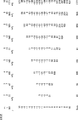
となり、[1]と同じ積和演算の形式に変形される。ここで、重み係数wVjの値と正規化定数WVの値とを図1に示す。図において、横方向はmの値および対応する正規化定数WVの値である。mの値はm=2,3,4,…であり、サンプル点の数を表している。縦方向は、サンプル点jに対応する重み係数wVjである。これらの値をテーブルとして保持することにより、サンプル値xjとの積和演算によりサンプル値終端での押鍵速度Vが算出される。なお、最下欄は、mの値に対応する重み係数wVjの和の値を示す。
If this is applied to the formula (SIGMA (wj * xj)) / W, the key pressing speed V at the end is
V = (SIGMA (wVj * xj)) / WV [25]
WV = T * m (m + 1) (2m + 1) (2m + 3) (2m-1) / 3 [26]
wVj = 30mj 2 + (2m + 3) (2m-1) j-10m 2 (m + 1) [27]
And transformed into the same product-sum operation format as [1]. Here, the value of the weight coefficient wVj and the value of the normalization constant WV are shown in FIG. In the figure, the horizontal direction is the value of m and the value of the corresponding normalization constant WV. The value of m is m = 2, 3, 4,... and represents the number of sample points. The vertical direction is a weighting factor wVj corresponding to the sample point j. By holding these values as a table, the key pressing speed V at the end of the sample value is calculated by the product-sum operation with the sample value xj. The bottom column indicates the sum value of the weighting factors wVj corresponding to the value of m.
1.3.サンプル点終端における押鍵深さ推測値(2次式)
次に、j=mにおける押鍵深さXは、[2][5][8][15]式より
X = c + b*m*T + a(m*T)2
= (SIGMA(wcj*xj))/Wc + (SIGMA(wbj*xj))/Wb *m*T + (SIGMA(waj*xj))/Wa *(m*T)2
と表される。第一項から第三項まで何れもSIGMAの加算範囲は−mからmであり、同一であるので、SIGMA内の各項がまとめられる。
よって、次式が得られる。
X = SIGMA( (wcj*xj))/Wc + (wbj*xj)/Wb*m*T + (waj*xj))/Wa*(m*T)2 )
= SIGMA( (wcj*WbWa/T3 + wbj*m*WcWa/T2 + waj*m2*WcWb/T)*xj )/ (WcWbWa/T3)
[31]
1.3. Estimated key pressing depth at the end of the sample point (secondary equation)
Next, the key depression depth X at j = m is calculated from [2] [5] [8] [15]
X = c + b * m * T + a (m * T) 2
= (SIGMA (wcj * xj)) / Wc + (SIGMA (wbj * xj)) / Wb * m * T + (SIGMA (waj * xj)) / Wa * (m * T) 2
It is expressed. In any of the first to third terms, the addition range of SIGMA is from -m to m, which are the same, so the terms in SIGMA are collected.
Therefore, the following equation is obtained.
X = SIGMA ((wcj * xj)) / Wc + (wbj * xj) / Wb * m * T + (waj * xj)) / Wa * (m * T) 2 )
= SIGMA ((wcj * WbWa / T 3 + wbj * m * WcWa / T 2 + waj * m 2 * WcWb / T) * xj) / (WcWbWa / T 3 )
[31]
[31]に[3][4][6][7][9][10]式をあてはめて
分母= (2m+1)(2m+3)(2m-1)/3 * T*m(m+1)(2m+1)/3 * T2*m(m+1)(2m+1)(2m+3)(2m-1)/15 /T3= m2(m+1)2(2m+1)3(2m+3)2(2m-1)2/135 [32]
分子=SIGMA( ((-5j2+3m(m+1)-1) * T*m(m+1)(2m+1)/3 * T2*m(m+1)(2m+1)(2m+3)(2m-1)/15/T3+ j *m* (2m+1)(2m+3)(2m-1)/3 * T2*m(m+1)(2m+1)(2m+3)(2m-1)/15/T2+ (3j2-m(m+1)) *m2* (2m+1)(2m+3)(2m-1)/3 * T*m(m+1)(2m+1)/3 /T )*xj )
= m2(m+1)(2m+1)2(2m+3)(2m-1)2/45*SIGMA( (5j2 + (2m+3)j - (m+1)(m-1) )*xj )
[33]
となる。
Apply [3] [4] [6] [7] [9] [10] to [31] and denominator = (2m + 1) (2m + 3) (2m-1) / 3 * T * m ( m + 1) (2m + 1) / 3 * T 2 * m (m + 1) (2m + 1) (2m + 3) (2m-1) / 15 / T 3 = m 2 (m + 1) 2 (2m + 1) 3 (2m + 3) 2 (2m-1) 2/135 [32]
Numerator = SIGMA (((-5j 2 + 3m (m + 1) -1) * T * m (m + 1) (2m + 1) / 3 * T 2 * m (m + 1) (2m + 1) (2m + 3) (2m-1) / 15 / T 3 + j * m * (2m + 1) (2m + 3) (2m-1) / 3 * T 2 * m (m + 1) (2m + 1) (2m + 3) (2m-1) / 15 / T 2 + (3j 2 -m (m + 1)) * m 2 * (2m + 1) (2m + 3) (2m-1) / 3 * T * m (m + 1) (2m + 1) / 3 / T) * xj)
= M 2 (m + 1) (2m + 1) 2 (2m + 3) (2m-1) 2/45 * SIGMA ((
[33]
It becomes.
したがって、 押鍵深さX は、
X = SIGMA((5j2+(2m+3)j-(m+1)(m-1))*xj) / ((m+1)(2m+1)(2m+3)/3) [34]
と表される。
Therefore, the key press depth X is
X = SIGMA ((5j 2 + (2m + 3) j- (m + 1) (m-1)) * xj) / ((m + 1) (2m + 1) (2m + 3) / 3) [ 34]
It is expressed.
これを式 (SIGMA(wj*xj))/W の形にあてはめると押鍵深さ X は、
X = (SIGMA(wXj*xj))/WX [35]
WX = (m+1)(2m+1)(2m+3)/3 [36]
wXj = 5j2+(2m+3)j-(m+1)(m-1) [37]
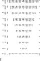
となり[1]式と同じ積和演算形式に変形される。ここで、mの値と重み係数wXjおよび正規化定数WXとの関係を図2に示す。
If this is applied to the form (SIGMA (wj * xj)) / W, the key depression depth X is
X = (SIGMA (wXj * xj)) / WX [35]
WX = (m + 1) (2m + 1) (2m + 3) / 3 [36]
wXj = 5j 2 + (2m + 3) j- (m + 1) (m-1) [37]
And transformed into the same product-sum operation format as [1]. Here, the relationship between the value of m, the weighting factor wXj, and the normalization constant WX is shown in FIG.
1.4.3次式近似
上記の各推測値は、押鍵深さを2次多項式で近似して算出したが、以下の3次多項式を用いて、さらに高精度な近似を行うことも出来る。
y = a*t3 + b*t2 + c*t + d
ここで、2次式の場合と同様に、最小自乗近似により各係数a,b,c,dが算出される。
係数 a は
a = (SIGMA(waj*xj))/Wa [42]
Wa = T3*m(m+1)(m+2)(m-1)(2m+1)(2m+3)(2m-1)/35 [43]
waj = j(5j2 - 3m2 - 3m + 1)
= j(5j2-3m(m+1)+1) [44]
係数 b は
b = (SIGMA(wbj*xj))/Wb [45]
Wb = T2*m(m+1)(2m+1)(2m+3)(2m-1)/15 [46]
wbj = 3j2-m2-m
= 3j2-m(m+1) [47]
係数 c は
c = (SIGMA(wcj*xj))/Wc [48]
Wc = T*m(m+1)(m+2)(m-1)(2m+1)(2m+3)(2m-1)/5 [49]
wcj = j(15m4+30m3-15m+5 - (21m2+21m-7)j2)
= j(-7(3m(m+1)-1)j2+5(3m(m+1)((m+2)(m-1)+1)+1)) [50]
係数 d は
d = (SIGMA(wdj*xj))/Wd [51]
Wd = (2m+1)(2m+3)(2m-1)/3 [52]
wdj = 3m2 + 3m - 1 - 5j2
= -5j2+3m(m+1)-1 [53]
である。このときの係数dの値が、j=0における押鍵深さの推測値である。
このように、3次近似式によって求められた係数bと2次式によって求められた係数aとが等しく、3次近似式によって求められた係数dと2次式によって求められた係数cとが等しい。
1.4. Approximation of cubic equation The above estimated values were calculated by approximating the key depression depth with a quadratic polynomial, but more accurate approximation can be performed using the following cubic polynomial. .
y = a * t 3 + b * t 2 + c * t + d
Here, as in the case of the quadratic expression, the coefficients a, b, c, and d are calculated by least square approximation.
The coefficient a is
a = (SIGMA (waj * xj)) / Wa [42]
Wa = T 3 * m (m + 1) (m + 2) (m-1) (2m + 1) (2m + 3) (2m-1) / 35 [43]
waj = j (5j 2 - 3m 2 - 3m + 1)
= j (5j 2 -3m (m + 1) +1) [44]
The coefficient b is
b = (SIGMA (wbj * xj)) / Wb [45]
Wb = T 2 * m (m + 1) (2m + 1) (2m + 3) (2m-1) / 15 [46]
wbj = 3j 2 -m 2 -m
= 3j 2 -m (m + 1) [47]
The coefficient c is
c = (SIGMA (wcj * xj)) / Wc [48]
Wc = T * m (m + 1) (m + 2) (m-1) (2m + 1) (2m + 3) (2m-1) / 5 [49]
wcj = j (15m 4 + 30m 3 -15m + 5-(21m 2 + 21m-7) j 2 )
= j (-7 (3m (m + 1) -1) j 2 +5 (3m (m + 1) ((m + 2) (m-1) +1) +1)) [50]
The coefficient d is
d = (SIGMA (wdj * xj)) / Wd [51]
Wd = (2m + 1) (2m + 3) (2m-1) / 3 [52]
wdj = 3m 2 + 3m-1-5j 2
= -5j 2 + 3m (m + 1) -1 [53]
It is. The value of the coefficient d at this time is an estimated value of the key depression depth when j = 0.
As described above, the coefficient b obtained by the cubic approximation expression is equal to the coefficient a obtained by the quadratic expression, and the coefficient d obtained by the cubic approximation expression and the coefficient c obtained by the quadratic expression are obtained. equal.
ここで
J 3次微分の推測値
Ac サンプル点中央(j=0)における加速度推測値
A サンプル点終端(j=m)における加速度推測値
Vc サンプル点中央(j=0)における速度推測値
V サンプル点終端(j=m)における速度推測値
Xc サンプル点中央(j=0)における位置推測値
X サンプル点終端(j=m)における位置推測値
とすると、これらと各係数との関係は、
J = 6a [54]
Ac = 2b [55]
Vc = c [56]
Xc = d [57]
A = Ac + J*m*T = 2b + 6a*m*T [58]
V = Vc + Ac*m*T + J/2*(m*T)2= c + 2b*m*T + 3a(m*T)2 [59]
X = Xc + Vc*m*T + A/2*(m*T)2 + J/6*(m*T)3
= d + c*m*T + b(m*T)2 + a(m*T)3 [60]
である。
Where J is the estimated value of the third derivative
Ac Estimated acceleration at the sample point center (j = 0)
A Estimated acceleration at the end of sample point (j = m)
Vc Estimated speed at the sample point center (j = 0)
V Estimated velocity at the sample point end (j = m)
Xc Estimated position at the sample point center (j = 0)
X Assuming the position at the end of the sample point (j = m), the relationship between these and each coefficient is
J = 6a [54]
Ac = 2b [55]
Vc = c [56]
Xc = d [57]
A = Ac + J * m * T = 2b + 6a * m * T [58]
V = Vc + Ac * m * T + J / 2 * (m * T) 2 = c + 2b * m * T + 3a (m * T) 2 [59]
X = Xc + Vc * m * T + A / 2 * (m * T) 2 + J / 6 * (m * T) 3
= d + c * m * T + b (m * T) 2 + a (m * T) 3 [60]
It is.
1.5.サンプル点終端における加速度推測値(3次式)
まず、複数のサンプル点の終端(j=m)における加速度推測値Aが、サンプル点中央における加速度推測値Ac=2bを用いて以下のように算出される。
[42][45][58]式より
A = 2b + 6a*m*T
= 2 (SIGMA(wbj*xj))/Wb + 6 (SIGMA(waj*xj))/Wa *m*T
が得られる。第一項も第二項も何れもSIGMAの加算範囲は−mからmであるので、SIGMA内の各項がまとめられる。よって、以下の式が得られる。
A = SIGMA( 2wbj*xj/Wb + 6waj*xj/Wa*m*T )
= SIGMA( (2wbj*Wa/T3 + 6waj*m*Wb/T2)*xj ) / (WbWa/T3)
[61]
1.5. Acceleration estimated value at the end of the sample point (third-order equation)
First, the estimated acceleration value A at the end (j = m) of a plurality of sample points is calculated as follows using the estimated acceleration value Ac = 2b at the center of the sample points.
From [42] [45] [58]
A = 2b + 6a * m * T
= 2 (SIGMA (wbj * xj)) / Wb + 6 (SIGMA (waj * xj)) / Wa * m * T
Is obtained. In both the first term and the second term, the addition range of SIGMA is from -m to m, so that each term in SIGMA is put together. Therefore, the following formula is obtained.
A = SIGMA (2wbj * xj / Wb + 6waj * xj / Wa * m * T)
= SIGMA ((2wbj * Wa / T 3 + 6waj * m * Wb / T 2 ) * xj) / (WbWa / T 3 )
[61]
[61]式に[43][44][46][47]式をあてはめて
分母
= T2*m(m+1) (2m+1)(2m+3)(2m-1)/15
* T3*m(m+1)(m+2)(m-1)(2m+1)(2m+3)(2m-1)/35 /T3
= T2*m2(m+1)2(m+2)(m-1)(2m+1)2(2m+3)2(2m-1)2/525 [62]
分子
=SIGMA( (2 (3j2-m(m+1))
* T3*m(m+1)(m+2)(m-1)(2m+1)(2m+3)(2m-1)/35 /T3
+ 6 j(5j2-(3m2+3m-1)) *m
* T2*m(m+1)(2m+1)(2m+3)(2m-1)/15 /T2)*xj )
= m(m+1)(2m+1)(2m+3)(2m-1)/105
*SIGMA( ( 6( 35mj3 + 3(m+2)(m-1)j2 - 7m(3m2+3m-1)j - m(m+1)(m+2)(m-1) )*xj ) [63]
になる。
Apply [43] [44] [46] [47] to [61] to denominator
= T 2 * m (m + 1) (2m + 1) (2m + 3) (2m-1) / 15
* T 3 * m (m + 1) (m + 2) (m-1) (2m + 1) (2m + 3) (2m-1) / 35 / T 3
= T 2 * m 2 (m + 1) 2 (m + 2) (m-1) (2m + 1) 2 (2m + 3) 2 (2m-1) 2/525 [62]
molecule
= SIGMA ((2 (3j 2 -m (m + 1))
* T 3 * m (m + 1) (m + 2) (m-1) (2m + 1) (2m + 3) (2m-1) / 35 / T 3
+ 6 j (5j 2- (3m 2 + 3m-1)) * m
* T 2 * m (m + 1) (2m + 1) (2m + 3) (2m-1) / 15 / T 2 ) * xj)
= m (m + 1) (2m + 1) (2m + 3) (2m-1) / 105
* SIGMA ((6 (35mj 3 + 3 (m + 2) (m-1) j 2 - 7m (
become.
したがって、A は
A = SIGMA(6(35mj3 + 3(m+2)(m-1)j2 - 7m(3m2+3m-1)j - m(m+1)(m+2)(m-1))*xj)
/ (T2*m(m+1)(m+2)(m-1)(2m+1)(2m+3)(2m-1)/5) [64]
と変形され、サンプル値終端における加速度推測値が求められる。
Therefore A is
A = SIGMA (6 (35mj 3 + 3 (m + 2) (m-1) j 2 - 7m (
/ (T 2 * m (m + 1) (m + 2) (m-1) (2m + 1) (2m + 3) (2m-1) / 5) [64]
The estimated acceleration value at the end of the sample value is obtained.
これを式 (SIGMA(wj*xj))/W の形にあてはめると終端における加速度推測値A は
A = (SIGMA(wAj*xj))/WA [65]
WA = T2*m(m+1)(m+2)(m-1)(2m+1)(2m+3)(2m-1)/5 [66]
wAj = 6(35mj3 + 3(m+2)(m-1)j2 - 7m(3m2+3m-1)j - m(m+1)(m+2)(m-1))
= 6(35mj3+3(m+2)(m-1)j2-7m(3m(m+1)-1)j-m(m+1)(m+2)(m-1)) [67]
となり[1]と同じ積和演算の形式に変形される。ここで、mの値を変化した場合における、重み係数wAjおよび正規化定数WAの各値を図3に示す。
If this is applied to the form of (SIGMA (wj * xj)) / W, the estimated acceleration value A at the end is
A = (SIGMA (wAj * xj)) / WA [65]
WA = T 2 * m (m + 1) (m + 2) (m-1) (2m + 1) (2m + 3) (2m-1) / 5 [66]
wAj = 6 (35mj 3 + 3 (m + 2) (m-1) j 2 - 7m (
= 6 (35mj 3 +3 (m + 2) (m-1) j 2 -7m (3m (m + 1) -1) jm (m + 1) (m + 2) (m-1)) (67 ]
And transformed into the same product-sum operation format as [1]. Here, FIG. 3 shows the values of the weighting factor wAj and the normalization constant WA when the value of m is changed.
1.6.サンプル値終端における速度推測値(3次式)
次に、j=mにおける押鍵速度Vは、[42][45][48][59]式より
V = c + 2b*m*T + 3a(m*T)2
= (SIGMA(wcj*xj))/Wc + 2 (SIGMA(wbj*xj))/Wb *m*T + 3 (SIGMA(waj*xj))/Wa *(m*T)2
となる。
1.6. Estimated speed at the end of sample value (third-order equation)
Next, the key pressing speed V at j = m is calculated from the equations [42] [45] [48] [59]
V = c + 2b * m * T + 3a (m * T) 2
= (SIGMA (wcj * xj)) / Wc + 2 (SIGMA (wbj * xj)) / Wb * m * T + 3 (SIGMA (waj * xj)) / Wa * (m * T) 2
It becomes.
第一項も第二項も何れもSIGMAの加算範囲は−mからmであるので、SIGMA内の各項がまとめられる。よって、以下の式が得られる。
V = SIGMA( (wcj*xj)/Wc + 2(wbj*xj)/Wb*m*T + 3(waj*xj)/Wa*(m*T)2 )
= SIGMA( (wcj*WbWa/T5 + 2wbj*m*WcWa/T4 + 3waj*m2*WcWb/T3)*xj )
/ (WcWbWa/T5) [71]
In both the first term and the second term, the addition range of SIGMA is from -m to m, so that each term in SIGMA is put together. Therefore, the following formula is obtained.
V = SIGMA ((wcj * xj ) / Wc + 2 (wbj * xj) / Wb * m * T + 3 (waj * xj ) / Wa * (m * T) 2 )
= SIGMA ((wcj * WbWa / T 5 + 2wbj * m * WcWa / T 4 + 3waj * m 2 * WcWb / T 3 ) * xj)
/ (WcWbWa / T 5 ) [71]
[71]式に[43][44][46][47][49][50]式をあてはめて、
分母
= T* m(m+1)(m+2)(m-1)(2m+1)(2m+3)(2m-1)/5
* T2*m(m+1) (2m+1)(2m+3)(2m-1)/15
* T3*m(m+1)(m+2)(m-1)(2m+1)(2m+3)(2m-1)/35 /T5
= T*m3(m+1)3(m+2)2(m-1)2(2m+1)3(2m+3)3(2m-1)3/2625 [72]
分子
=SIGMA( ( j(-7(3m2+3m-1)j2 + 5(3m4+6m3-3m+1))
* T2*m(m+1) (2m+1)(2m+3)(2m-1)/15
* T3*m(m+1)(m+2)(m-1)(2m+1)(2m+3)(2m-1)/35 /T5
+ 2 (3j2-m(m+1)) *m
* T* m(m+1)(m+2)(m-1)(2m+1)(2m+3)(2m-1)/5
* T3*m(m+1)(m+2)(m-1)(2m+1)(2m+3)(2m-1)/35 /T4
+ 3 j(5j2-(3m2+3m-1)) *m2
* T* m(m+1)(m+2)(m-1)(2m+1)(2m+3)(2m-1)/5
* T2*m(m+1)(2m+1)(2m+3)(2m-1)/15 /T3 )*xj )
= m2(m+1)2(m+2)(m-1)(2m+1)2(2m+3)2(2m-1)2/525
*SIGMA( 7(12m2-3m+1)j3 + 18m(m+2)(m-1)j2
+ (-48m4-33m3+21m2-15m+5)j - 6m2(m+1)(m+2)(m-1) )*xj )
[73]
が得られる。
Apply [43] [44] [46] [47] [49] [50] to [71],
denominator
= T * m (m + 1) (m + 2) (m-1) (2m + 1) (2m + 3) (2m-1) / 5
* T 2 * m (m + 1) (2m + 1) (2m + 3) (2m-1) / 15
* T 3 * m (m + 1) (m + 2) (m-1) (2m + 1) (2m + 3) (2m-1) / 35 / T 5
= T * m 3 (m + 1) 3 (m + 2) 2 (m-1) 2 (2m + 1) 3 (2m + 3) 3 (2m-1) 3/2625 [72]
molecule
= SIGMA ((j (-7 (3m 2 + 3m-1) j 2 +5 (3m 4 + 6m 3 -3m + 1))
* T 2 * m (m + 1) (2m + 1) (2m + 3) (2m-1) / 15
* T 3 * m (m + 1) (m + 2) (m-1) (2m + 1) (2m + 3) (2m-1) / 35 / T 5
+ 2 (3j 2 -m (m + 1)) * m
* T * m (m + 1) (m + 2) (m-1) (2m + 1) (2m + 3) (2m-1) / 5
* T 3 * m (m + 1) (m + 2) (m-1) (2m + 1) (2m + 3) (2m-1) / 35 / T 4
+ 3 j (5j 2- (3m 2 + 3m-1)) * m 2
* T * m (m + 1) (m + 2) (m-1) (2m + 1) (2m + 3) (2m-1) / 5
* T 2 * m (m + 1) (2m + 1) (2m + 3) (2m-1) / 15 / T 3 ) * xj)
= M 2 (m + 1) 2 (m + 2) (m-1) (2m + 1) 2 (2m + 3) 2 (2m-1) 2/525
* SIGMA (7 (12m 2 -3m + 1) j 3 + 18m (m + 2) (m-1) j 2
+ (-48m 4 -33m 3 + 21m 2 -15m + 5) j-6m 2 (m + 1) (m + 2) (m-1)) * xj)
[73]
Is obtained.
よって 、速度推測値V は
V = SIGMA( 7(12m2-3m+1)j3 + 18m(m+2)(m-1)j2
- (48m4+33m3-21m2+15m-5)j - 6m2(m+1)(m+2)(m-1) )*xj )
/ (T*m(m+1)(m+2)(m-1)(2m+1)(2m+3)(2m-1)/5)
[74]
となる。
Therefore, the estimated speed value V is
V = SIGMA (7 (12m 2 -3m + 1) j 3 + 18m (m + 2) (m-1) j 2
-(48m 4 + 33m 3 -21m 2 + 15m-5) j-6m 2 (m + 1) (m + 2) (m-1)) * xj)
/ (T * m (m + 1) (m + 2) (m-1) (2m + 1) (2m + 3) (2m-1) / 5)
[74]
It becomes.
これを式 (SIGMA(wj*xj))/W の形に当てはめると、押鍵速度V は
V = (SIGMA(wVj*xj))/WV [75]
WV = T*m(m+1)(m+2)(m-1)(2m+1)(2m+3)(2m-1)/5 [76]
wVj = 7(12m2-3m+1)j3 + 18m(m+2)(m-1)j2
- (48m4+33m3-21m2+15m-5)j - 6m2(m+1)(m+2)(m-1)
= 7(3m(4m-1)+1)j3 + 18m(m+2)(m-1)j2
- (3m(m(m(16m+11)-7)+5)-5)j - 6m2(m+1)(m+2)(m-1) [77]
となり[1]と同じ積和演算形式に変形される。ここで、mの値を変化した場合における、重み係数wVjおよび正規化係数WVの値を図4に示す。
Applying this to the form of (SIGMA (wj * xj)) / W, the key pressing speed V is
V = (SIGMA (wVj * xj)) / WV [75]
WV = T * m (m + 1) (m + 2) (m-1) (2m + 1) (2m + 3) (2m-1) / 5 [76]
wVj = 7 (12m 2 -3m + 1) j 3 + 18m (m + 2) (m-1) j 2
-(48m 4 + 33m 3 -21m 2 + 15m-5) j-6m 2 (m + 1) (m + 2) (m-1)
= 7 (3m (4m-1) +1) j 3 + 18m (m + 2) (m-1) j 2
-(3m (m (m (16m + 11) -7) +5) -5) j-6m 2 (m + 1) (m + 2) (m-1) [77]
And transformed into the same product-sum operation format as [1]. Here, FIG. 4 shows values of the weighting coefficient wVj and the normalization coefficient WV when the value of m is changed.
1.7.サンプル値終端における押鍵深さ推測値(3次式)
次に、j=mにおける押鍵深さXは、[42][45][48][51][60]式より
X = d + c*m*T + b(m*T)2 + a(m*T)3
= (SIGMA(wdj*xj))/Wd + (SIGMA(wcj*xj))/Wc *m*T
+ (SIGMA(wbj*xj))/Wb *(m*T)2 + (SIGMA(waj*xj))/Wa *(m*T)3
となる。
1.7. Estimated key press depth at the end of sample value (3rd order)
Next, the key depression depth X at j = m is calculated from the equations [42] [45] [48] [51] [60]
X = d + c * m * T + b (m * T) 2 + a (m * T) 3
= (SIGMA (wdj * xj)) / Wd + (SIGMA (wcj * xj)) / Wc * m * T
+ (SIGMA (wbj * xj)) / Wb * (m * T) 2 + (SIGMA (waj * xj)) / Wa * (m * T) 3
It becomes.
第一項も第二項も何れもSIGMAの加算範囲は−mからmであるので、SIGMA内の各項がまとめられる。よって、以下の式が得られる。
X = SIGMA( (wdj*xj))/Wd + (wcj*xj)/Wc*m*T
+ (wbj*xj))/Wb*(m*T)2 + (waj*xj))/Wa*(m*T)3 )
= SIGMA( (wdj*WcWbWa/T6 + wcj*m*WdWbWa/T5 + wbj*m2*WdWcWa/T4
+ waj*m3*WdWcWb/T3)*xj )/ (WdWcWbWa/T6) [81]
In both the first term and the second term, the addition range of SIGMA is from -m to m, so that each term in SIGMA is put together. Therefore, the following formula is obtained.
X = SIGMA ((wdj * xj)) / Wd + (wcj * xj) / Wc * m * T
+ (wbj * xj)) / Wb * (m * T) 2 + (waj * xj)) / Wa * (m * T) 3 )
= SIGMA ((wdj * WcWbWa / T 6 + wcj * m * WdWbWa / T 5 + wbj * m 2 * WdWcWa / T 4
+ waj * m 3 * WdWcWb / T 3 ) * xj) / (WdWcWbWa / T 6 ) [81]
[81]式に[43][44][46][47][49][50][52][53]式をあてはめて
分母
= (2m+1)(2m+3)(2m-1)/3
* T* m(m+1)(m+2)(m-1)(2m+1)(2m+3)(2m-1)/5
* T2*m(m+1) (2m+1)(2m+3)(2m-1)/15
* T3*m(m+1)(m+2)(m-1)(2m+1)(2m+3)(2m-1)/35 /T6
= m3(m+1)3(m+2)2(m-1)2(2m+1)4(2m+3)4(2m-1)4/7875 [82]
分子
=SIGMA( ( (-5j2+3m2+3m-1)
* T* m(m+1)(m+2)(m-1)(2m+1)(2m+3)(2m-1)/5
* T2*m(m+1) (2m+1)(2m+3)(2m-1)/15
* T3*m(m+1)(m+2)(m-1)(2m+1)(2m+3)(2m-1)/35 /T6
+ j(-7(3m2+3m-1)j2 + 5(3m4+6m3-3m+1)) *m
* (2m+1)(2m+3)(2m-1)/3
* T2*m(m+1) (2m+1)(2m+3)(2m-1)/15
* T3*m(m+1)(m+2)(m-1)(2m+1)(2m+3)(2m-1)/35 /T5
+ (3j2-m(m+1)) *m2
* (2m+1)(2m+3)(2m-1)/3
* T* m(m+1)(m+2)(m-1)(2m+1)(2m+3)(2m-1)/5
* T3*m(m+1)(m+2)(m-1)(2m+1)(2m+3)(2m-1)/35 /T4
+ j(5j2-(3m2+3m-1)) *m3
* (2m+1)(2m+3)(2m-1)/3
* T* m(m+1)(m+2)(m-1)(2m+1)(2m+3)(2m-1)/5
* T2*m(m+1)(2m+1)(2m+3)(2m-1)/15 /T3 )*xj )
= m3(m+1)2(m+2)(m-1)2(2m+1)3(2m+3)3(2m-1)4/7875
*SIGMA( ( 35j3 + 15(m+2)j2 - 5(3m2-5)j - 3(m+1)(m+2)(m-1) )*xj )
となる。
Apply [43] [44] [46] [47] [49] [50] [52] [53] to the expression [81] to denominator
= (2m + 1) (2m + 3) (2m-1) / 3
* T * m (m + 1) (m + 2) (m-1) (2m + 1) (2m + 3) (2m-1) / 5
* T 2 * m (m + 1) (2m + 1) (2m + 3) (2m-1) / 15
* T 3 * m (m + 1) (m + 2) (m-1) (2m + 1) (2m + 3) (2m-1) / 35 / T 6
= M 3 (m + 1) 3 (m + 2) 2 (m-1) 2 (2m + 1) 4 (2m + 3) 4 (2m-1) 4/7875 [82]
molecule
= SIGMA (((-5j 2 + 3m 2 + 3m-1)
* T * m (m + 1) (m + 2) (m-1) (2m + 1) (2m + 3) (2m-1) / 5
* T 2 * m (m + 1) (2m + 1) (2m + 3) (2m-1) / 15
* T 3 * m (m + 1) (m + 2) (m-1) (2m + 1) (2m + 3) (2m-1) / 35 / T 6
+ j (-7 (3m 2 + 3m-1) j 2 + 5 (3m 4 + 6m 3 -3m + 1)) * m
* (2m + 1) (2m + 3) (2m-1) / 3
* T 2 * m (m + 1) (2m + 1) (2m + 3) (2m-1) / 15
* T 3 * m (m + 1) (m + 2) (m-1) (2m + 1) (2m + 3) (2m-1) / 35 / T 5
+ (3j 2 -m (m + 1)) * m 2
* (2m + 1) (2m + 3) (2m-1) / 3
* T * m (m + 1) (m + 2) (m-1) (2m + 1) (2m + 3) (2m-1) / 5
* T 3 * m (m + 1) (m + 2) (m-1) (2m + 1) (2m + 3) (2m-1) / 35 / T 4
+ j (5j 2- (3m 2 + 3m-1)) * m 3
* (2m + 1) (2m + 3) (2m-1) / 3
* T * m (m + 1) (m + 2) (m-1) (2m + 1) (2m + 3) (2m-1) / 5
* T 2 * m (m + 1) (2m + 1) (2m + 3) (2m-1) / 15 / T 3 ) * xj)
= M 3 (m + 1) 2 (m + 2) (m-1) 2 (2m + 1) 3 (2m + 3) 3 (2m-1) 4/7875
* SIGMA ((35j 3 + 15 (m + 2) j 2 - 5 (3m 2 -5) j - 3 (m + 1) (m + 2) (m-1)) * xj)
It becomes.
したがって、押鍵深さX は、
X = SIGMA( ( 35j3 + 15(m+2)j2 - 5(3m2-5)j - 3(m+1)(m+2)(m-1) )*xj )
/ ((m+1)(m+2)(2m+1)(2m+3)) [84]
と表される。
Therefore, the key depression depth X is
X = SIGMA ((35j 3 + 15 (m + 2) j 2 - 5 (3m 2 -5) j - 3 (m + 1) (m + 2) (m-1)) * xj)
/ ((m + 1) (m + 2) (2m + 1) (2m + 3)) [84]
It is expressed.
これを式 (SIGMA(wj*xj))/W の形にあてはめると係数 X は
X = (SIGMA(wXj*xj))/WX [85]
WX = (m+1)(m+2)(2m+1)(2m+3) [86]
wXj = 35j3 + 15(m+2)j2 - 5(3m2-5)j - 3(m+1)(m+2)(m-1)
[87]
となり[1]と同じ積和演算形式に変形される。mの値を変化した場合における重み係数wXjおよび正規化係数WXの値を図5に示す。
If this is applied to the form of (SIGMA (wj * xj)) / W, the coefficient X is
X = (SIGMA (wXj * xj)) / WX [85]
WX = (m + 1) (m + 2) (2m + 1) (2m + 3) [86]
wXj = 35j 3 + 15 (m + 2) j 2 - 5 (3m 2 -5) j - 3 (m + 1) (m + 2) (m-1)
[87]
And transformed into the same product-sum operation format as [1]. FIG. 5 shows values of the weighting factor wXj and the normalization factor WX when the value of m is changed.
すなわち、2次式で近似した場合、3次式で近似した場合の何れも、重み係数wXおよび正規化定数WXの値をテーブルとして記憶することにより、サンプル値終端の推測値を求めることが出来る。 That is, in both cases of approximation by a quadratic equation and approximation by a cubic equation, the estimated value of the end of the sample value can be obtained by storing the values of the weighting factor wX and the normalization constant WX as a table. .
2.実施例の構成
2.1.ハードウェア構成
本発明の一実施例である自動演奏ピアノ(雑音除去装置)のハードウェア構成を図6に示す。
図において、10はソレノイドであり、電流制御によりプランジャ部分が軸方向に変位する。20はハンマセンサであり、一次側にフォトダイオード、二次側にフォトトランジスタを設けたフォトセンサを、2個、並列して設けたセンサである。なお、一方のフォトセンサが遮光状態になってから双方のフォトセンサが遮光状態になるまでの時間差から打弦タイミングと打弦速度とが検出される。25は変位検出型キーセンサであり、押下位置を検出して、そのデータをアナログ出力する。27はフォトセンサ型キーセンサであり、ハンマセンサと同様の原理で、キーオンタイミングと押鍵速度とを検出する。
2. Example configuration
2.1. Hardware Configuration FIG. 6 shows a hardware configuration of an automatic performance piano (noise removal apparatus) according to an embodiment of the present invention.
In the figure,
30はPWM発生器であり、矩形波電流のパルス幅を可変することにより、ソレノイド10に供給される平均電流を制御する。35はA/D変換器であり、変位検出型キーセンサ25から出力されたアナログ信号をデジタル信号に変換する。37はI/Oインターフェースであり、ハンマセンサ20およびフォトセンサ型キーセンサ27の出力信号を波形整形する。なお、ソレノイド10、ハンマセンサ20、変位検出型キーセンサ25、フォトセンサ型キーセンサ27、I/Oインターフェース37は、鍵盤の各鍵にそれぞれ設けられる。40はフレキシブルディスクドライブであり、演奏情報等を記憶したフレキシブルディスクが挿入される。50はCPUであり、後述するアルゴリズムに基づいて各部を制御する。52はフラッシュROMであり、パラメータおよびプログラムならびに前述したテーブルが記憶されている。54はRAMであり、CPU50のワークメモリとして使用される。なお、変位検出型キーセンサ25によって検出された変位情報が位置記憶レジスタの値としてRAM54内に記憶される。60はバスラインであり、各部を接続する。以上の要素により、自動演奏ピアノ100が構成される。
A
2.2.鍵部の機構
次に、自動演奏ピアノの鍵部の概要構成を図7に示す。
図において70は鍵であり、バランスピン80によって揺動自在に支持されている。また、演奏情報記録用のキー位置センサ27は、鍵70の前方(図上右側)下面に対向して設けられている。鍵70の前方下面には、該フォトセンサ型キーセンサ27を遮光する遮光板75が鍵70の下方に向かって突出するように設けられている。15はプランジャであり、ソレノイド10の一部を構成し、ソレノイド10に供給される電流により上下方向に変位し、鍵70を駆動する。90はアクション機構であり、鍵70の運動をハンマ2に伝達する。4は弦であり、ハンマ2によって打弦される。6はダンパであり、弦4を制動する。
2.2. Next, a schematic configuration of the key part of the automatic performance piano is shown in FIG.
In the figure,
また、CPU50によって実行される機能は、記録メディアあるいはリアルタイム通信装置から供給される演奏情報に基づいて、鍵の軌道リファランスを生成する再生前処理部110と、供給された軌道リファランスと変位検出型キーセンサ25の出力信号すなわち各時刻における鍵70の位置とに対応した制御信号を生成し該制御信号に応じた励磁電流をソレノイド10に供給するモーション制御部120と、ハンマセンサ20およびフォトセンサ型キーセンサ27の出力信号に基づいて演奏情報を記憶する演奏記録部130と、この演奏情報に対して各種補正を行う記録後処理部150とから構成されている。
The functions executed by the
ここで、本自動演奏ピアノは消音機能を有するものであるが、これはハンマが打弦する直前にハンマの回動を阻止する構成を有するものであって、具体的には、ハンマシャンクの回動を阻止するストッパ(図示略)を設けるものである。そして通常演奏時には、このストッパをハンマの回動を阻止しない位置に配置し、消音演奏時にはこのストッパをハンマの回動を阻止しない位置に配置するものである。このようなストッパを有する消音機構は公知のものを使用すればよく、その詳細構成についての説明を省略する。 Here, this automatic performance piano has a mute function, but this has a structure that prevents the hammer from rotating immediately before the hammer strikes. Specifically, the hammer shank rotates. A stopper (not shown) for preventing movement is provided. During normal performance, this stopper is disposed at a position that does not prevent the hammer from rotating, and during mute performance, this stopper is disposed at a position that does not prevent the hammer from rotating. A known silencer mechanism having such a stopper may be used, and a detailed description thereof is omitted.
3.自動演奏ピアノの動作
3.1.演奏情報記録段階
本実施例の自動演奏ピアノ100の動作は、図示しないコントローラにおける記録指示に基づき実際に演奏者が演奏を行いその演奏情報を記録する演奏情報記録段階と、図示しないコントローラにおける再生指示に基づき該演奏情報に基づいて演奏を自動的に再生する再生段階とに区分される。
演奏情報記録段階においては、操作者によって演奏が行われる。すなわち、押鍵操作に連動してハンマによる打弦が行われる。それにより、ハンマセンサ20によって打弦タイミングと打弦速度とが検出され、フォトセンサ型キーセンサ27によって、キーオンタイミングと押鍵速度とが検出される。そして、演奏記録部130により、何れの鍵を押鍵したかという情報であるキーコードと共に、これらの押鍵速度、打弦速度、キーオンタイミング、打弦タイミングが、演奏情報としてRAM54に記憶される。同様に、キーオフタイミング、離鍵速度、キーコードが記憶される。次に、記録後処理部150により、例えばイベント抜け等の不具合が修正され、その結果得られた最終的な演奏情報の全体がフレキシブルディスクに記録される。
3. Automatic piano performance
3.1. Performance Information Recording Stage The operation of the
In the performance information recording stage, a performance is performed by an operator. That is, hammering is performed in conjunction with the key pressing operation. Thereby, the
3.2.再生段階
再生段階においては、再生前処理部110により、フレキシブルディスクから演奏情報が読み込まれ、該演奏情報に基づいて特許文献1記載の技術により、押鍵深さを表す軌道リファランスが生成される。そして、モーション制御部120にあっては、この軌道リファランスを目標値として、鍵70の押鍵深さ、押鍵速度がサーボ制御される。ここで、押鍵深さ、押鍵速度の目標値は軌道リファランスに基づいて一意に得られるが、変位検出型キーセンサ25によって検出された押鍵深さには雑音が混入されるので、その影響を除去する必要がある。その処理の詳細を図9を参照し説明する。
3.2. Reproduction Stage In the reproduction stage, performance information is read from the flexible disk by the
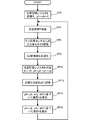
図9において処理がステップSP2に進むと、RAM54内に設けられた位置記憶レジスタy0〜y6の値が「0」にリセットされる。なお、位置記憶レジスタy0〜y6は、過去「7」サンプルに渡る変位検出型キーセンサ25の実測値を記憶するためのレジスタである。次に、処理がステップSP4に進むと、サンプリング間隔に相当する所定時間Tだけ処理が待機される。次に、処理がステップSP6に進むと、変位検出型キーセンサ25からの入力信号をAD変換した結果が取得される。
In FIG. 9, when the process proceeds to step SP2, the values of the position storage registers y0 to y6 provided in the
次に、処理がステップSP8に進むと、このステップSP6において得られた値が正規化される。すなわち、鍵70や変位検出型キーセンサ25等には個体差があるため、正規化処理により、この個体差が補償される。次に処理がステップSP10に進むと、位置記憶レジスタy0〜y6の内容が「1」段階だけシフトされる。すなわち、元々位置記憶レジスタy0〜y5に記憶されていた内容が、各々位置記憶レジスタy1〜y6にシフトされる。次に、処理がステップSP12に進むと、先にステップSP8によって得られた、正規化された押鍵位置が位置記憶レジスタy0に記憶される。すなわち、ここでは過去「7」サンプルが直近の位置として逐次更新される。
Next, when the process proceeds to step SP8, the value obtained in step SP6 is normalized. That is, since there are individual differences in the key 70, the displacement detection type
次に、処理がステップSP14に進むと、位置記憶レジスタy0〜y6の内容および重み係数wVj,正規化係数WVの値に基づいて、直近の押鍵速度Vが算出される。すなわち、図1においてm=3(n=7)の欄を参照すると、重み係数wVjは「j=−3〜3」の範囲において「7,−2,−7,−8,−5,2,13」であるから、これらの値が各々位置記憶レジスタy6,y5,y4,y3,y2,y1,y0の内容に乗算され、これら乗算結果の総和が求められ、求められた総和が正規化係数WV(=「28」)で除算され、この除算結果が直近の押鍵速度Vの推定値になる。 Next, when the process proceeds to step SP14, the latest key pressing speed V is calculated based on the contents of the position storage registers y0 to y6 and the values of the weighting coefficient wVj and the normalization coefficient WV. That is, referring to the column of m = 3 (n = 7) in FIG. 1, the weight coefficient wVj is “7, −2, −7, −8, −5, 2” in the range of “j = −3 to 3”. , 13 ", these values are multiplied by the contents of the position storage registers y6, y5, y4, y3, y2, y1, y0, respectively, and the sum of these multiplication results is obtained, and the obtained sum is normalized. Dividing by the coefficient WV (= “28”), the result of the division becomes the estimated value of the latest key pressing speed V.
次に、処理がステップSP16に進むと、位置記憶レジスタy0〜y6の内容および重み係数wXj,正規化係数WXの値に基づいて、直近の押鍵深さXが算出される。すなわち、図2においてm=3(n=7)の欄を参照すると、重み係数wVjは「j=−3〜3」の範囲において「5,−3,−6,−4,3,15,32」であるから、これらの値が各々位置記憶レジスタy6,y5,y4,y3,y2,y1,y0の内容に乗算され、これら乗算結果の総和が求められ、求められた総和が正規化係数WX(=「42」)で除算され、この除算結果が直近の押鍵深さXの推定値になる。以下、ステップSP4〜SP16の処理が繰り返されることにより、直近の押鍵速度Vおよび押鍵深さXの推定値が逐次算出される。そして、これらの推定値と目標値との差分に基づいて、鍵70がサーボ制御される。 Next, when the process proceeds to step SP16, the latest key pressing depth X is calculated based on the contents of the position storage registers y0 to y6, the weighting factor wXj, and the normalization factor WX. That is, referring to the column of m = 3 (n = 7) in FIG. 2, the weighting factor wVj is “5−3, −6, −4, 3, 15, 32 ", these values are multiplied by the contents of the position storage registers y6, y5, y4, y3, y2, y1, y0, respectively, and the sum of these multiplication results is obtained, and the obtained sum is the normalization coefficient. Dividing by WX (= “42”), the result of the division becomes the estimated value of the latest key pressing depth X. Hereinafter, the estimated values of the latest key pressing speed V and key pressing depth X are sequentially calculated by repeating the processes of steps SP4 to SP16. Then, the key 70 is servo-controlled based on the difference between the estimated value and the target value.
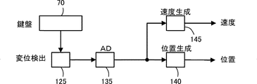
次に、図9において説明した処理と等価なアルゴリズムのブロック図を図8に示す。
まず、RAM54に設けられた位置記憶レジスタxj(j=−3,…,3)の値が「0」に初期化される。次に、鍵盤70の押鍵深さ情報が、変位検出型キーセンサ25の機能(変位検出ユニット125)を介して検出される。そして、A/D変換ユニット135によって、変位検出型キーセンサ25のアナログ出力がデジタルデータに変換され、検出された押鍵深さが位置記憶レジスタxj(j=3)に記憶される。なお、時刻t=0においては、押鍵状態でないので、「0」の値が位置記憶レジスタxj(j=3)に記憶される。
Next, FIG. 8 shows a block diagram of an algorithm equivalent to the processing described in FIG.
First, the value of the position storage register xj (j = −3,..., 3) provided in the
次に、フラッシュROM52から重み係数wXjと正規化定数WXの値が読み出される。図2によれば、具体的な値はサンプル番号j=−3,−2,−1,0,1,2,3のときに、重み係数wXj=5,−3,−6,−4,3,15,32であり、正規化定数WX=42である。次に、[35]式に基づいて、次式の積和演算が実行される。
X = (SIGMA(wXj*xj))/WX
すなわち、位置生成ユニット140によって、サンプル値xjと重み係数wXjとが積和演算され、その積和演算結果が正規化定数WX=42によって除算される。それにより、サンプル値終端(j=3)における押鍵深さの推測値Xが算出される。
Next, the values of the weighting factor wXj and the normalization constant WX are read from the
X = (SIGMA (wXj * xj)) / WX
That is, the
同様に、フラッシュROM52から重み係数wVjと正規化定数WVの値が読み出される。図1によれば、具体的な値はサンプル番号j=−3,−2,−1,0,1,2,3のときに、重み係数wVj=7,−2,−7,−8,−5,2,13であり、正規化定数WV=28である。[25]式に基づいて、次式の積和演算が実行される。
V = (SIGMA(wVj*xj))/WV
すなわち、速度生成ユニット145によって、サンプル値xjと重み係数wVjとが積和演算され、その積和演算結果が規格化定数WX=28によって除算される。それにより、サンプル値終端(j=3)における押鍵速度Vの推測値が算出される。
Similarly, the values of the weighting factor wVj and the normalization constant WV are read from the
V = (SIGMA (wVj * xj)) / WV
That is, the
一方、鍵70はソレノイド10の駆動によって回動するように構成されている。したがって、検出された鍵70の押鍵深さの推測値Xおよび押鍵速度の推測値Vが目標鍵軌道データの押鍵深さあるいは押鍵速度に近づくように、ソレノイド10に供給される電流がPWM発生器30を介して制御され、鍵軌道が再生される。そして、ソレノイド10によって駆動された鍵70に連動して、アクション機構のハンマが打弦する。
On the other hand, the key 70 is configured to rotate by driving the
次に、位置記憶レジスタの内容がシフトされる。すなわち、xj(j=3)の値がxj(j=2)にシフトされる。同時に、xj(j=2)の内容がxj(j=1)にシフトされる。以下同様に、xj(j=−2)の内容がxj(j=−3)にシフトされ、xj(j=−3)の内容が廃棄される。シフト完了後再び、変位検出型キーセンサ25によって検出された押鍵深さが位置記憶レジスタxj(j=3)に記憶され、積和演算およびソレノイド10の駆動が一定時間間隔で繰り返され、鍵軌道が時々刻々制御される。
Next, the contents of the position storage register are shifted. That is, the value of xj (j = 3) is shifted to xj (j = 2). At the same time, the contents of xj (j = 2) are shifted to xj (j = 1). Similarly, the contents of xj (j = -2) are shifted to xj (j = -3), and the contents of xj (j = -3) are discarded. After the shift is completed, the key depression depth detected by the displacement detection type
以上のように本実施例によれば、変位検出型キーセンサ25の出力データが多項式により近似されるので、該データに含まれるノイズが除去される。すなわち、フィードバック制御に好適な信号が得られる。また、サンプル値終端の推測値を直接求めることが出来るため、サンプル値中央の推測値に(微分値*m*サンプリング周期)の値を乗じてサンプル値終端の推測値を求める場合よりも計算量が少ない。
As described above, according to the present embodiment, since the output data of the displacement detection type
4.変形例
本発明は上述した実施例に限定されるものではなく、例えば以下のように種々の変形が可能であり、全て本発明の範疇に含まれる。
(1)上記実施例においては、鍵の駆動を行ったがペダルの駆動を行ってもよい。また、管楽器等の操作子を有する楽器に応用することが可能である。
(2)上記実施例においては、自動演奏ピアノの押鍵深さを検出した信号に雑音除去方法を使用したが、産業用ロボットその他の装置に使用することが出来る。
Four. Modifications The present invention is not limited to the above-described embodiments. For example, various modifications are possible as follows, and all are included in the scope of the present invention.
(1) In the above embodiment, the key is driven, but the pedal may be driven. Further, the present invention can be applied to a musical instrument having an operator such as a wind instrument.
(2) In the above embodiment, the noise removal method is used for the signal for detecting the key depression depth of the automatic performance piano, but it can be used for industrial robots and other devices.
(3)上記実施例においては、重み係数wjとサンプル値xjとの積和演算した結果を正規化定数Wで除算したが、サンプル値xjを正規化定数Wで除算した値と重み係数wjとの積和演算を行ってもよい。また、重み係数wjの値を正規化係数Wによって除した値とサンプル値xjとの積和演算を行うこともできるし、この重み係数wjの値を正規化係数Wによって除した値をテーブルとして記憶しておくこともできる。さらに、入力信号に比例したサンプル値xjと重み係数wjとの積和演算した結果、すなわち変位、速度に比例する値を、正規化定数Wで除算せずに、制御信号として使用することも出来る。
(4)上記実施例においては、サンプル値を2次, 3次多項式で近似して算出された重み係数、正規化係数を用いたが、より高次の多項式で近似した重み係数、正規化係数を用いてもよい。
(3) In the above embodiment, the product-sum operation result of the weighting factor wj and the sample value xj is divided by the normalization constant W, but the value obtained by dividing the sample value xj by the normalization constant W and the weighting factor wj The product-sum operation may be performed. Also, the product-sum operation of the value obtained by dividing the value of the weighting factor wj by the normalization factor W and the sample value xj can be performed, and the value obtained by dividing the value of the weighting factor wj by the normalization factor W is used as a table. You can also remember it. Furthermore, the result of product-sum operation of the sample value xj proportional to the input signal and the weighting factor wj, that is, the value proportional to the displacement and speed can be used as a control signal without being divided by the normalization constant W. .
(4) In the above embodiment, the weighting coefficient and the normalization coefficient calculated by approximating the sample value with the second-order and third-order polynomials are used. However, the weighting coefficient and the normalization coefficient approximated with a higher-order polynomial. May be used.
(5)上記実施例においては、フラッシュROM52に格納されたプログラムによって雑音除去方法を実行したが、パーソナルコンピュータ上で動作するアプリケーションプログラムによっても実行することが出来る。このアプリケーションプログラムをCD−ROM、フレキシブルディスク等の記憶媒体に格納して頒布し、あるいは電気通信回線を通じて頒布してもよい。
(6)また、位置の記憶はシフトレジスタに限られるものではなく、リングバッファなど適切な構成を用いればよい。なお、リングバッファを用いる場合は、内容のシフトではなく、参照アドレスを変更するだけでよい。
(7)上記実施例においては、位置記憶レジスタxj(j=−3,…,3)の値が「0」に初期化されたが、初期値は「0」でなくてもよい。例えば、そのときの系の運動状態を把握しておき、それに対応する初期値を設定してもよい。
(8)また、上記実施例においては、サンプル数nを奇数にしたが、これは偶数であってもよい。また、サンプリング間隔も等間隔でなくてもよい。これらの場合は、それぞれに適した重み付け係数、正規化係数を求めて適用するとよい。
(5) In the above embodiment, the noise removal method is executed by the program stored in the
(6) The storage of the position is not limited to the shift register, and an appropriate configuration such as a ring buffer may be used. When a ring buffer is used, it is only necessary to change the reference address instead of shifting the contents.
(7) In the above embodiment, the value of the position storage register xj (j = −3,..., 3) is initialized to “0”, but the initial value may not be “0”. For example, the movement state of the system at that time may be grasped, and an initial value corresponding to it may be set.
(8) Moreover, in the said Example, although the sample number n was made into the odd number, this may be an even number. Also, the sampling interval may not be equal. In these cases, a weighting coefficient and a normalization coefficient suitable for each may be obtained and applied.
5.実施態様
本発明には、以下のような実施態様がある。
(1) 前記サンプル点の数は、サンプル番号j=-m からm までの(2m+1)個であり、
前記多項近似式は、前記入力された信号についての2次近似式であり、
j番目のサンプル値に対する前記重み係数は、{5j2+(2m+3)j-(m+1)(m-1) }に比例する値である
ことを特徴とする請求項1記載の雑音除去方法。
Five. Embodiments The present invention has the following embodiments.
(1) The number of sample points is (2m + 1) from sample number j = -m to m,
The polynomial approximation is a quadratic approximation for the input signal,
The noise according to
(2) 前記サンプル点の数は、サンプル番号j=-m からm までの(2m+1)個であり、
前記多項近似式は、前記入力された信号の微分についての2次近似式であり、
j番目のサンプル値に対する前記重み係数は、{30mj2+(2m+3)(2m-1)j-10m2(m+1)}に比例する値である
ことを特徴とする請求項1記載の雑音除去方法。
(2) The number of sample points is (2m + 1) from sample number j = -m to m,
The polynomial approximation is a quadratic approximation for the differentiation of the input signal,
the weight factor for the j-th sample value, {30mj 2 + (2m + 3) (2m-1) j-10m 2 (m + 1)} , characterized in that a value proportional to
(3) 前記サンプル点の数は、サンプル番号j=-m からm までの(2m+1)個であり、
前記多項近似式は、前記入力された信号についての3次近似式であり、
j番目のサンプル値に対する前記重み係数は、{35j3 + 15(m+2)j2 - 5(3m2-5)j - 3(m+1)(m+2)(m-1) }に比例する値である
ことを特徴とする請求項1記載の雑音除去方法。
(3) The number of sample points is (2m + 1) from sample number j = -m to m,
The polynomial approximation is a cubic approximation for the input signal,
the weight factor for the j-th sample value, {35j 3 + 15 (m + 2) j 2 - 5 (3m 2 -5) j - 3 (m + 1) (m + 2) (m-1)} The noise removal method according to
(4) 前記サンプル点の数は、サンプル番号j=-m からm までの(2m+1)個であり、
前記多項近似式は、前記入力された信号の微分についての3次近似式であり、
j番目のサンプル値に対する前記重み係数は、{7(3m(4m-1)+1)j3 + 18m(m+2)(m-1)j2- (3m(m(m(16m+11)-7)+5)-5)j - 6m2(m+1)(m+2)(m-1) }に比例する値である
ことを特徴とする請求項1記載の雑音除去方法。
(4) The number of sample points is (2m + 1) from sample number j = -m to m,
The polynomial approximation is a cubic approximation for the differentiation of the input signal,
The weighting factor for the jth sample value is {7 (3m (4m-1) +1) j 3 + 18m (m + 2) (m-1) j 2- (3m (m (m (16m + 11 The noise removal method according to
(5) 前記サンプル点の数は、サンプル番号j=-m からm までの(2m+1)個であり、
前記多項近似式は、前記入力された信号の2階微分についての3次近似式であり、
j番目のサンプル値に対する前記重み係数は、{6(35mj3+3(m+2)(m-1)j2-7m(3m(m+1)-1)j-m(m+1)(m+2)(m-1)) }に比例する値である
ことを特徴とする請求項1記載の雑音除去方法。
(5) The number of sample points is (2m + 1) from sample number j = -m to m,
The polynomial approximation is a third-order approximation for the second derivative of the input signal,
The weighting factor for the jth sample value is {6 (35mj 3 +3 (m + 2) (m-1) j 2 -7m (3m (m + 1) -1) jm (m + 1) (m The method according to
10…ソレノイド、20…ハンマセンサ、25…変位検出型キーセンサ、27…フォトセンサ型キーセンサ、30…PWM発生器、35…A/D変換器、37…I/Oインターフェース、40…フレキシブルディスクユニット、50…CPU、52…フラッシュROM、54…RAM、60…バスライン、70…鍵、80…バランスピン、90…アクション機構、100…自動演奏ピアノ(雑音除去装置)、125…変位検出ユニット、135…A/D変換ユニット、140…位置生成ユニット、145…速度生成ユニット。
DESCRIPTION OF
Claims (4)
前記移動物体の位置を測定するセンサと、
前記センサからの情報を定期的にサンプリングするサンプリング手段と、
該サンプリング手段でサンプリングされたサンプル値を、予め定めた所定サンプル数記憶する第1の記憶手段と、
前記所定サンプル数によって決定される重み係数であって、前記位置の近似値を求める位置近似多項式における該位置の近似値と複数の前記サンプル値との自乗誤差を最小にする、前記位置近似多項式の係数に基づいて定められた重み係数を記憶する第2の記憶手段と、
該第2の記憶手段から前記重み係数を読み出す読出し手段と、
前記サンプル値と前記重み係数とを乗算し、これらの乗算結果を加算することによって前記移動物体のサンプル点終端の位置または速度を推定する演算手段と
を具備することを特徴とする推定装置。 An estimation device for estimating the position or speed of a moving object,
A sensor for measuring the position of the moving object;
Sampling means for periodically sampling information from the sensor;
First storage means for storing a predetermined number of samples, the sample value sampled by the sampling means;
A weighting factor determined by the predetermined number of samples , wherein the position approximation polynomial of the position approximation polynomial minimizes a square error between the position approximation polynomial and the position approximation polynomial for obtaining the position approximation value. Second storage means for storing a weighting factor determined based on the coefficient ;
Reading means for reading the weighting coefficient from the second storage means;
An estimation device comprising: an arithmetic unit that multiplies the sample value by the weighting factor and adds the multiplication results to estimate a position or velocity of a sample point end of the moving object.
前記各操作子毎に設けられ、供給された駆動信号に応じてこれら操作子を駆動する複数のアクチュエータと、
前記各操作子毎に設けられ、これら操作子の変位を測定し、該測定された変位を表す検出信号を出力する複数のセンサと、
供給された演奏情報に従って、前記各操作子の軌道リファランスを決定する軌道リファランス決定手段と、
各々の前記操作子について、複数回に渡る前記検出信号のサンプル値と該サンプル値の数によって決定される所定の重み係数との積の加算結果を計算することによって、サンプル点終端における位置または速度の推測値である終端推測値を決定する終端推測値決定手段であって、前記重み係数は、前記変位の近似値を求める変位近似多項式における該変位の近似値と複数の前記サンプル値との自乗誤差を最小にする、前記変位近似多項式の係数に基づいて定められた重み係数である、終端推測値決定手段と、
逐次計算される前記終端推測値が、前記軌道リファランスに基づく目標値に近づくように前記駆動信号を出力する駆動信号出力手段と
を具備することを特徴とする自動楽器。 A plurality of controls that generate musical sounds when driven;
A plurality of actuators provided for each of the operating elements, and driving the operating elements in accordance with the supplied drive signal;
A plurality of sensors provided for each of the operating elements , measuring displacements of these operating elements , and outputting detection signals representing the measured displacements ;
Orbit reference determining means for determining the orbit reference of each of the operators according to the supplied performance information;
For each of the operators, the position or velocity at the end of the sample point is calculated by calculating the addition result of the product of the sample value of the detection signal over a plurality of times and a predetermined weighting factor determined by the number of sample values. A terminal estimated value determining means for determining a terminal estimated value that is an estimated value of the displacement, wherein the weighting factor is a square of the approximate value of the displacement and a plurality of sample values in a displacement approximation polynomial for obtaining an approximate value of the displacement. A terminal estimated value determining means that is a weighting coefficient determined based on a coefficient of the displacement approximation polynomial that minimizes an error ;
An automatic musical instrument comprising: drive signal output means for outputting the drive signal so that the estimated end value calculated sequentially approaches a target value based on the trajectory reference.
前記センサからの情報を定期的にサンプリングするサンプリング過程と、
該サンプリング過程でサンプリングされたサンプル値を、予め定めた所定サンプル数だけ第1の記憶手段に記憶する過程と、
前記所定サンプル数によって決定される重み係数であって、前記位置の近似値を求める位置近似多項式における該位置の近似値と複数の前記サンプル値との自乗誤差を最小にする、前記位置近似多項式の係数に基づいて定められた重み係数を第2の記憶手段から読み出す読出し過程と、
前記サンプル値と前記重み係数とを乗算し、これらの乗算結果を加算することによって前記移動物体のサンプル点終端の位置または速度を推定する演算過程と
を前記処理装置に実行させることを特徴とするプログラム。 A program that is applied to an estimation device that has a processing device and estimates the position or velocity of a moving object based on information from a sensor that measures the position of the moving object,
A sampling process for periodically sampling information from the sensor;
Storing the sample values sampled in the sampling process in the first storage means by a predetermined number of samples;
A weighting factor determined by the predetermined number of samples , wherein the position approximation polynomial of the position approximation polynomial minimizes a square error between the position approximation polynomial and the position approximation polynomial for obtaining the position approximation value. A reading process of reading a weighting factor determined based on the coefficient from the second storage means;
The processing device is caused to perform a calculation process of multiplying the sample value by the weighting factor and adding the multiplication results to estimate the position or velocity of the sample point end of the moving object. program.
前記各操作子毎に設けられ、供給された駆動信号に応じてこれら操作子を駆動する複数のアクチュエータと、
前記各操作子毎に設けられ、これら操作子の変位を測定し、該測定された変位を表す検出信号を出力する複数のセンサと、
処理装置と
を有する自動楽器に適用されるプログラムであって、
供給された演奏情報に従って、前記各操作子の軌道リファランスを決定する軌道リファランス決定過程と、
各々の前記操作子について、複数回に渡る前記検出信号のサンプル値と所定の重み係数との積の加算結果を計算することによって、サンプル点終端における位置または速度の推測値である終端推測値を決定する終端推測値決定過程であって、前記重み係数は、前記位置の近似値を求める位置近似多項式における該位置の近似値と複数の前記サンプル値との自乗誤差を最小にする、前記位置近似多項式の係数に基づいて定められた重み係数である、終端推測値決定過程と、
前記終端推測値と、前記軌道リファランス上の対応する目標値との差に基づいて前記駆動信号を出力する駆動信号出力過程と
を前記処理装置に実行させることを特徴とするプログラム。 A plurality of controls that generate musical sounds when driven;
A plurality of actuators provided for each of the operating elements, and driving the operating elements in accordance with the supplied drive signal;
A plurality of sensors provided for each of the operating elements , measuring displacements of these operating elements , and outputting detection signals representing the measured displacements ;
A program applied to an automatic musical instrument having a processing device,
A trajectory reference determination process for determining a trajectory reference for each of the controls according to the supplied performance information;
For each of the operators, by calculating the addition result of the product of the sample value of the detection signal over a plurality of times and a predetermined weighting factor , a terminal estimated value that is an estimated value of the position or velocity at the sample point terminal is obtained. Determining a terminal estimated value to be determined, wherein the weighting factor minimizes a square error between an approximate value of the position and a plurality of sample values in a position approximation polynomial for obtaining an approximate value of the position. A terminal estimated value determination process , which is a weighting factor determined based on a coefficient of a polynomial ,
A program causing the processing device to execute a drive signal output process of outputting the drive signal based on a difference between the estimated end value and a corresponding target value on the trajectory reference.
Priority Applications (4)
| Application Number | Priority Date | Filing Date | Title |
|---|---|---|---|
| JP2003374315A JP4075771B2 (en) | 2003-11-04 | 2003-11-04 | Estimation device, automatic musical instrument and program |
| US10/971,283 US7390956B2 (en) | 2003-11-04 | 2004-10-21 | Automatic player musical instrument, noise suppressor incorporated therein, method used therein and computer program for the method |
| EP04025794.1A EP1530194A3 (en) | 2003-11-04 | 2004-10-29 | Automatic player musical instrument having a method and device for suppressing a noise component |
| CN2004100897704A CN1614683B (en) | 2003-11-04 | 2004-11-04 | Automatic player musical instrument, noise suppressor incorporated therein and method |
Applications Claiming Priority (1)
| Application Number | Priority Date | Filing Date | Title |
|---|---|---|---|
| JP2003374315A JP4075771B2 (en) | 2003-11-04 | 2003-11-04 | Estimation device, automatic musical instrument and program |
Publications (3)
| Publication Number | Publication Date |
|---|---|
| JP2005140830A JP2005140830A (en) | 2005-06-02 |
| JP2005140830A5 JP2005140830A5 (en) | 2006-11-02 |
| JP4075771B2 true JP4075771B2 (en) | 2008-04-16 |
Family
ID=34431257
Family Applications (1)
| Application Number | Title | Priority Date | Filing Date |
|---|---|---|---|
| JP2003374315A Expired - Fee Related JP4075771B2 (en) | 2003-11-04 | 2003-11-04 | Estimation device, automatic musical instrument and program |
Country Status (4)
| Country | Link |
|---|---|
| US (1) | US7390956B2 (en) |
| EP (1) | EP1530194A3 (en) |
| JP (1) | JP4075771B2 (en) |
| CN (1) | CN1614683B (en) |
Cited By (1)
| Publication number | Priority date | Publication date | Assignee | Title |
|---|---|---|---|---|
| US10167569B2 (en) | 2012-08-16 | 2019-01-01 | National University Corporation Ehime University | Hexagonal diamond bulk sintered body and its manufacturing method |
Families Citing this family (16)
| Publication number | Priority date | Publication date | Assignee | Title |
|---|---|---|---|---|
| JP4218552B2 (en) * | 2004-03-04 | 2009-02-04 | ヤマハ株式会社 | Keyboard instrument |
| EP1575026A2 (en) * | 2004-03-12 | 2005-09-14 | Yamaha Corporation | Automatic player musical instrument, for exactly controlling the keys |
| JP4193752B2 (en) * | 2004-05-07 | 2008-12-10 | ヤマハ株式会社 | Automatic piano |
| JP4524798B2 (en) * | 2004-07-27 | 2010-08-18 | ヤマハ株式会社 | Method and apparatus for identifying half point of pedal of keyboard instrument, and program |
| JP2007025351A (en) * | 2005-07-19 | 2007-02-01 | Yamaha Corp | Playing system |
| JP4711179B2 (en) * | 2005-08-19 | 2011-06-29 | ヤマハ株式会社 | Electronic keyboard instruments and programs |
| JP5298437B2 (en) * | 2006-03-08 | 2013-09-25 | ヤマハ株式会社 | Keyboard instrument |
| JP4736883B2 (en) * | 2006-03-22 | 2011-07-27 | ヤマハ株式会社 | Automatic performance device |
| JP5023709B2 (en) * | 2006-04-03 | 2012-09-12 | 株式会社デンソー | Communication system and communication apparatus |
| JP5056197B2 (en) * | 2007-06-22 | 2012-10-24 | ヤマハ株式会社 | Performance support apparatus and performance apparatus |
| WO2009108437A1 (en) * | 2008-02-27 | 2009-09-03 | Steinway Musical Instruments, Inc. | Pianos playable in acoustic and silent modes |
| JP5560777B2 (en) * | 2009-03-13 | 2014-07-30 | ヤマハ株式会社 | Keyboard instrument |
| US8541673B2 (en) | 2009-04-24 | 2013-09-24 | Steinway Musical Instruments, Inc. | Hammer stoppers for pianos having acoustic and silent modes |
| US8148620B2 (en) * | 2009-04-24 | 2012-04-03 | Steinway Musical Instruments, Inc. | Hammer stoppers and use thereof in pianos playable in acoustic and silent modes |
| JP6402502B2 (en) * | 2014-06-20 | 2018-10-10 | ヤマハ株式会社 | Performance information output control device, keyboard instrument and control method |
| CN109478397B (en) * | 2017-01-18 | 2021-05-18 | 森兰信息科技(上海)有限公司 | Automatic playing system |
Family Cites Families (8)
| Publication number | Priority date | Publication date | Assignee | Title |
|---|---|---|---|---|
| US5254804A (en) * | 1989-03-31 | 1993-10-19 | Yamaha Corporation | Electronic piano system accompanied with automatic performance function |
| JP3596015B2 (en) | 1993-12-17 | 2004-12-02 | ヤマハ株式会社 | Automatic piano |
| US5652399A (en) * | 1993-12-17 | 1997-07-29 | Yamaha Corporation | Automatic player piano and estimator for acceleration of depressed key incorporated in the automatic player piano |
| JP3620063B2 (en) * | 1994-03-25 | 2005-02-16 | ヤマハ株式会社 | Automatic piano and performance data processing device |
| JP3588872B2 (en) * | 1995-09-19 | 2004-11-17 | ヤマハ株式会社 | Automatic piano |
| JP3807030B2 (en) * | 1997-01-14 | 2006-08-09 | ヤマハ株式会社 | Keyboard musical instrument, electronic musical instrument and method, and recording medium |
| JP3890649B2 (en) * | 1997-02-21 | 2007-03-07 | ヤマハ株式会社 | Automatic piano performance data converter |
| CN1218294C (en) * | 2001-09-18 | 2005-09-07 | 武汉科恒工控工程有限责任公司 | Automatic piano playing system |
-
2003
- 2003-11-04 JP JP2003374315A patent/JP4075771B2/en not_active Expired - Fee Related
-
2004
- 2004-10-21 US US10/971,283 patent/US7390956B2/en active Active
- 2004-10-29 EP EP04025794.1A patent/EP1530194A3/en not_active Withdrawn
- 2004-11-04 CN CN2004100897704A patent/CN1614683B/en not_active Expired - Fee Related
Cited By (1)
| Publication number | Priority date | Publication date | Assignee | Title |
|---|---|---|---|---|
| US10167569B2 (en) | 2012-08-16 | 2019-01-01 | National University Corporation Ehime University | Hexagonal diamond bulk sintered body and its manufacturing method |
Also Published As
| Publication number | Publication date |
|---|---|
| US20050092160A1 (en) | 2005-05-05 |
| CN1614683B (en) | 2010-06-16 |
| EP1530194A2 (en) | 2005-05-11 |
| CN1614683A (en) | 2005-05-11 |
| EP1530194A3 (en) | 2016-12-14 |
| US7390956B2 (en) | 2008-06-24 |
| JP2005140830A (en) | 2005-06-02 |
Similar Documents
| Publication | Publication Date | Title |
|---|---|---|
| JP4075771B2 (en) | Estimation device, automatic musical instrument and program | |
| JP4479554B2 (en) | Keyboard instrument | |
| JP4483636B2 (en) | Keyboard instrument | |
| JP6015192B2 (en) | Fatigue testing machine | |
| JP4193752B2 (en) | Automatic piano | |
| JP4636364B2 (en) | Performance operator drive method, performance operator drive device, program, and automatic piano | |
| KR101456361B1 (en) | Musical instrument, method for obtaining control data based on an operating position of a pedal in a musical instrument, method for reproducing operation of a pedal in a musical instrument | |
| JP2006235216A (en) | Reproduction driver of musical instrument performance, keyboard instrument, and automatic playing piano | |
| JP4639795B2 (en) | Musical instrument performance drive device, keyboard instrument performance drive system, and keyboard instrument. | |
| JP4375200B2 (en) | Basic information output device for haptic control | |
| JP2014021233A (en) | Keyboard instrument | |
| JP2011081380A (en) | Theremin performance robot | |
| Fujisaki et al. | In-tool motion sensing for evaluation of violin performance | |
| JP2006084686A (en) | Device, method, and program for physical quantity detection, and keyboard musical instrument | |
| JP4345690B2 (en) | Keyboard instrument and operating element reaction force optimization system | |
| JP2005195773A (en) | Performing system | |
| JP4134952B2 (en) | Automatic piano | |
| JP6736930B2 (en) | Electronic musical instrument and sound signal generation method | |
| JP2692356B2 (en) | Electronic musical instrument | |
| JP4296664B2 (en) | Solenoid drive control device and solenoid drive control method | |
| JP2004294769A (en) | Playing operation element driving device | |
| JP3055788B2 (en) | Vibration characteristic analysis method and device | |
| JP5298437B2 (en) | Keyboard instrument | |
| JP4232663B2 (en) | Driving device for performance operator of automatic musical instrument and driving method thereof | |
| JP3873823B2 (en) | Reproduction performance evaluation device, musical instrument and keyboard musical instrument |
Legal Events
| Date | Code | Title | Description |
|---|---|---|---|
| A621 | Written request for application examination |
Free format text: JAPANESE INTERMEDIATE CODE: A621 Effective date: 20060623 |
|
| A521 | Written amendment |
Free format text: JAPANESE INTERMEDIATE CODE: A523 Effective date: 20060915 |
|
| A977 | Report on retrieval |
Free format text: JAPANESE INTERMEDIATE CODE: A971007 Effective date: 20070416 |
|
| A131 | Notification of reasons for refusal |
Free format text: JAPANESE INTERMEDIATE CODE: A131 Effective date: 20070424 |
|
| A521 | Written amendment |
Free format text: JAPANESE INTERMEDIATE CODE: A523 Effective date: 20070615 |
|
| A131 | Notification of reasons for refusal |
Free format text: JAPANESE INTERMEDIATE CODE: A131 Effective date: 20070904 |
|
| A521 | Written amendment |
Free format text: JAPANESE INTERMEDIATE CODE: A523 Effective date: 20071030 |
|
| TRDD | Decision of grant or rejection written | ||
| A01 | Written decision to grant a patent or to grant a registration (utility model) |
Free format text: JAPANESE INTERMEDIATE CODE: A01 Effective date: 20080108 |
|
| A61 | First payment of annual fees (during grant procedure) |
Free format text: JAPANESE INTERMEDIATE CODE: A61 Effective date: 20080121 |
|
| R150 | Certificate of patent or registration of utility model |
Free format text: JAPANESE INTERMEDIATE CODE: R150 Ref document number: 4075771 Country of ref document: JP Free format text: JAPANESE INTERMEDIATE CODE: R150 |
|
| FPAY | Renewal fee payment (event date is renewal date of database) |
Free format text: PAYMENT UNTIL: 20110208 Year of fee payment: 3 |
|
| FPAY | Renewal fee payment (event date is renewal date of database) |
Free format text: PAYMENT UNTIL: 20120208 Year of fee payment: 4 |
|
| FPAY | Renewal fee payment (event date is renewal date of database) |
Free format text: PAYMENT UNTIL: 20130208 Year of fee payment: 5 |
|
| FPAY | Renewal fee payment (event date is renewal date of database) |
Free format text: PAYMENT UNTIL: 20140208 Year of fee payment: 6 |
|
| LAPS | Cancellation because of no payment of annual fees |