JP4075151B2 - Image processing apparatus and image processing method - Google Patents
Image processing apparatus and image processing method Download PDFInfo
- Publication number
- JP4075151B2 JP4075151B2 JP24640898A JP24640898A JP4075151B2 JP 4075151 B2 JP4075151 B2 JP 4075151B2 JP 24640898 A JP24640898 A JP 24640898A JP 24640898 A JP24640898 A JP 24640898A JP 4075151 B2 JP4075151 B2 JP 4075151B2
- Authority
- JP
- Japan
- Prior art keywords
- image
- parallax image
- parallax
- image sequence
- images
- Prior art date
- Legal status (The legal status is an assumption and is not a legal conclusion. Google has not performed a legal analysis and makes no representation as to the accuracy of the status listed.)
- Expired - Fee Related
Links
- 238000003672 processing method Methods 0.000 title claims description 11
- 230000002194 synthesizing effect Effects 0.000 claims description 14
- 230000015572 biosynthetic process Effects 0.000 claims description 6
- 238000003786 synthesis reaction Methods 0.000 claims description 6
- 238000000034 method Methods 0.000 description 24
- 230000003287 optical effect Effects 0.000 description 18
- 238000010586 diagram Methods 0.000 description 9
- 238000009792 diffusion process Methods 0.000 description 9
- 238000003384 imaging method Methods 0.000 description 7
- 238000004091 panning Methods 0.000 description 5
- 238000006243 chemical reaction Methods 0.000 description 2
- 239000004065 semiconductor Substances 0.000 description 2
- 230000000694 effects Effects 0.000 description 1
- 238000012840 feeding operation Methods 0.000 description 1
- 239000004973 liquid crystal related substance Substances 0.000 description 1
- 239000012466 permeate Substances 0.000 description 1
- 230000001172 regenerating effect Effects 0.000 description 1
Images


Classifications
-
- G—PHYSICS
- G03—PHOTOGRAPHY; CINEMATOGRAPHY; ANALOGOUS TECHNIQUES USING WAVES OTHER THAN OPTICAL WAVES; ELECTROGRAPHY; HOLOGRAPHY
- G03H—HOLOGRAPHIC PROCESSES OR APPARATUS
- G03H1/00—Holographic processes or apparatus using light, infrared or ultraviolet waves for obtaining holograms or for obtaining an image from them; Details peculiar thereto
- G03H1/26—Processes or apparatus specially adapted to produce multiple sub- holograms or to obtain images from them, e.g. multicolour technique
- G03H1/268—Holographic stereogram
-
- G—PHYSICS
- G03—PHOTOGRAPHY; CINEMATOGRAPHY; ANALOGOUS TECHNIQUES USING WAVES OTHER THAN OPTICAL WAVES; ELECTROGRAPHY; HOLOGRAPHY
- G03H—HOLOGRAPHIC PROCESSES OR APPARATUS
- G03H2210/00—Object characteristics
- G03H2210/40—Synthetic representation, i.e. digital or optical object decomposition
- G03H2210/44—Digital representation
- G03H2210/441—Numerical processing applied to the object data other than numerical propagation
-
- G—PHYSICS
- G03—PHOTOGRAPHY; CINEMATOGRAPHY; ANALOGOUS TECHNIQUES USING WAVES OTHER THAN OPTICAL WAVES; ELECTROGRAPHY; HOLOGRAPHY
- G03H—HOLOGRAPHIC PROCESSES OR APPARATUS
- G03H2210/00—Object characteristics
- G03H2210/50—Nature of the object
- G03H2210/54—For individualisation of product
Landscapes
- Physics & Mathematics (AREA)
- General Physics & Mathematics (AREA)
- Holo Graphy (AREA)
- Image Generation (AREA)
- Studio Circuits (AREA)
- Testing, Inspecting, Measuring Of Stereoscopic Televisions And Televisions (AREA)
- Processing Of Color Television Signals (AREA)
- Processing Or Creating Images (AREA)
Description
【0001】
【発明の属する技術分野】
本発明は、ホログラフィックステレオグラムの作成等に使用される視差画像列を作成する画像処理装置及び画像処理方法に関する。
【0002】
【従来の技術】
視差情報を有する複数の画像からなる視差画像列は、例えば、立体的な画像を表示するホログラフィックステレオグラムの作成に使用される。ホログラフィックステレオグラムは、被写体を異なる視点から順次撮影することにより得られた多数の画像からなる視差画像列を原画として、これらを1枚のホログラム用記録媒体に短冊状又はドット状の要素ホログラムとして順次記録することにより作成される。
【0003】
例えば、横方向のみに視差情報を持つホログラフィックステレオグラムを作成する際は、図8に示すように、先ず、被写体100を横方向の異なる観察点から順次撮影することにより、横方向の視差情報を有する複数の画像からなる視差画像列101を得る。そして、この視差画像列101を構成する画像102を、必要に応じて所定の視点変換処理等を施した上で、短冊状の要素ホログラムとしてホログラム用記録媒体103に横方向に連続するように順次記録する。これにより、横方向に視差情報を持つホログラフィックステレオグラムが得られる。
【0004】
このホログラフィックステレオグラムは、当該ホログラフィックステレオグラムをある位置から片方の目で見た場合、各要素ホログラムの一部分の画像情報の集合体である二次元画像が見え、目の位置を水平方向に動かせば、各要素ホログラムの別の部分の画像情報の集合体である二次元画像が見える。したがって、このホログラフィックステレオグラムを観察者が両目で見たときには、左右の目の位置が水平方向で若干異なるため、それぞれに写る二次元画像は若干異なるものとなる。これにより、観察者は視差を感じ、立体画像が認識される。なお、このようなホログラフィックステレオグラムに関しては、例えば特開平10−20756号などに記載されている。
【0005】
このようなホログラフィックステレオグラムの原画像となる視差画像列を撮影する際は、撮影装置を動かしながら、異なる方向から被写体を順次撮影する。これにより、視差情報を有する複数の画像からなる視差画像列が得られる。具体的には例えば、撮影装置として、1秒あたり30フレームの撮影を行うビデオカメラを使用し、当該ビデオカメラを一定の速度で動かしながら、連続して被写体を撮影する。このとき、例えば7.5秒にわたって被写体を撮影したとすると、225フレーム分の撮影がなされ、その結果、被写体に対する視点の異なる225枚の画像からなる視差画像列が得られる。
【0006】
【発明が解決しようとする課題】
視差画像列は、異なる方向から被写体を順次撮影することにより得られるので、視差画像列の撮影には、ある程度の時間がかかる。被写体が静物であれば、視差画像列の撮影に要する時間が多少長くてもあまり問題はない。しかし、被写体が静物でない場合(例えば被写体が人物の場合など)には、撮影中に被写体が動いてしまう可能性があるため、視差画像列の撮影に要する時間を出来るだけ短くすることが望まれる。
【0007】
しかし、単位時間あたりに撮影可能な枚数が決まっている場合に、視差画像列の撮影に要する時間を短くすると、視差画像列を構成する画像の枚数が少なくなってしまう。視差画像列を構成する画像の枚数が少なくなると、当該視差画像列をもとに得られる立体画像の画質が劣化してしまう。
【0008】
すなわち、視差画像列の撮影に要する時間と、当該視差画像列をもとに得られる立体画像の画質とは、トレードオフの関係にあり、従来、視差画像列の撮影に要する時間を短縮しつつ、当該視差画像列をもとに得られる立体画像の画質を十分に維持することは難しかった。
【0009】
本発明は、以上のような従来の実情に鑑みて提案されたものであり、視差画像列の撮影に要する時間を短縮しつつ、当該視差画像列をもとに得られる立体画像の画質を維持することを可能とする画像処理装置及び画像処理方法を提供すること目的とする。
【0010】
【課題を解決するための手段】
本発明に係る画像処理装置は、視差情報を有する複数の画像からなる視差画像列を作成する画像処理装置において、動的被写体の視差画像列と背景の視差画像列とを撮影する撮影手段と、撮影手段により撮影された、背景の視差画像列とこの背景の視差画像列を構成する画像の枚数よりも少ない枚数からなる動的被写体の視差画像列との視差画像列を構成する画像の枚数を一致させる画像枚数調整手段と、画像枚数調整手段により画像の枚数が一致させられた視差画像列同士を合成して、新たな視差画像列を生成する画像合成手段とを備える。そして、画像枚数調整手段は、動的被写体の視差画像列を構成する画像の枚数を、動的被写体の視差画像列を構成する画像に基づく画像を追加して、背景の視差画像列を構成する画像の枚数に一致させることを特徴とする。
【0011】
また、本発明に係る画像処理方法は、視差情報を有する複数の画像からなる視差画像列を作成する画像処理方法において、動的被写体の視差画像列と背景の視差画像列とを撮影する撮影工程と、撮影工程により撮影された、背景の視差画像列とこの背景の視差画像列を構成する画像の枚数より少ない枚数からなる動的被写体の視差画像列との視差画像列を構成する画像の枚数を一致させる画像枚数調整工程と、画像枚数調整工程により画像の枚数が一致させられた視差画像列同士を合成して、新たな視差画像列を生成する画像合成工程とを有する。そして、画像枚数調整工程は、動的被写体の視差画像列を構成する画像の枚数を、動的被写体の視差画像列を構成する画像に基づく画像を追加して、背景の視差画像列を構成する画像の枚数に一致させることを特徴とする。
【0012】
一般に、視差画像列をもとに立体画像を再現する場合、再生像の画質を維持するのに必要な元画像枚数は、再生像の定位する位置によって異なる。例えば、視差画像列を構成する各画像をホログラム用記録媒体に要素ホログラムとして順次記録してホログラフィックステレオグラムを作成する場合、ホログラム記録媒体面よりも奥に再生像が定位する場合と、ホログラム記録媒体面上に再生像が定位する場合と、ホログラム記録媒体面よりも手前に再生像が定位する場合とで、同等の画質を維持するのに必要な元画像枚数は異なる。これは、再生像が定位する位置によって、各視点間での画像の相関性に差があるからである。
【0013】
したがって、再生像の定位する位置によって、視差画像列の枚数を変えて被写体の撮影を行うようにすれば、再生像の定位する位置に合わせた最適な枚数の視差画像列の撮影が可能となる。換言すれば、必要以上の撮影を省くことが可能となり、視差画像列の撮影に要する時間を短縮することが出来る。しかしながら、このように得られた複数組の視差画像列のままでは、立体画像を再現することは出来ない。
【0014】
そこで、本発明においては、先ず、撮影手段により撮影された背景の視差画像列と該背景の視差画像列を構成する画像の枚数よりも少ない枚数からなる動的被写体の視差画像列とについて、それらの視差画像列を構成する画像の枚数を一致させ、その後、画像の枚数が一致させられた視差画像列同士を合成して、新たな視差画像列を作成するようにしている。これにより、枚数の異なる動的被写体の視差画像列と背景の視差画像列とから、立体画像のもととなる一組の視差画像列を作成することが可能となる。
【0015】
【発明の実施の形態】
以下、本発明の実施の形態について、図面を参照しながら詳細に説明する。なお、以下の説明では、ホログラフィックステレオグラム作成システムに本発明を適用した例に挙げるが、本発明に係る画像処理装置及び画像処理方法は、視差画像列が必要とされる分野において広く適用可能である。例えば、視差を利用して表示装置に立体的な画像を表示するようなときにも視差画像列は必要とされ、このような場合にも本発明に係る画像処理装置及び画像処理方法は適用可能である。
【0016】
本発明を適用した画像処理装置の一構成例を図1に示す。この画像処理装置1は、人物等の被写体を撮影して視差画像列を得て、当該視差画像列に予め撮影された背景となる視差画像列を合成して、新たな視差画像列を作成するものであり、図1に示すように、撮影装置2と、映像信号処理装置3と、映像信号記録再生装置4と、映像信号再生装置5と、クロマキー合成装置6と、これらの装置全体の動作を制御する制御用コンピュータ7とを備える。
【0017】
撮影装置2は、人物等の被写体を撮影するためのものであり、例えばCCDカメラからなる。そして、視差画像列を撮影する際は、この撮影装置2を動かしながら、異なる方向から被写体を順次撮影する。そして、この撮影装置2によって撮影された視差画像列の映像信号は、映像信号処理装置3に送られる。
【0018】
映像信号処理装置3は、撮影装置2によって被写体を撮影することによって得られた視差画像列の映像信号を所定の形式に変換するためのものであり、例えばD1デコーダからなる。撮影装置2からの映像信号は、この映像信号処理装置3によって所定の形式に変換された上で、映像信号記録再生装置4に送られる。
【0019】
映像信号記録再生装置4は、記録媒体に映像信号を記録したり、或いは、記録媒体に記録された映像信号を再生するためのものである。ここで、記録媒体としては、例えば、光ディスク、磁気ディスク、磁気テープ又は半導体メモリ等が用いられる。そして、この映像信号記録再生装置4は、映像信号処理装置3によって所定の形式とされた映像信号を受け取り、当該映像信号を記録媒体に記録する。また、この映像信号記録再生装置4は、必要に応じて、制御用コンピュータ7からの指示により、記録媒体に記録された映像信号を読み出して再生する。映像信号記録再生装置4によって再生された映像信号は、例えばNTSC信号として、クロマキー合成装置6に送られる。
【0020】
また、この映像信号記録再生装置4は、記録媒体から映像信号を再生する際に、必要に応じて、制御用コンピュータ7からの指示により、同じフレームの映像信号を繰り返し出力する。換言すれば、この映像信号記録再生装置4は、必要に応じて、制御用コンピュータ7からの指示により、記録媒体から再生された映像信号のフレーム数よりも、出力する映像信号のフレーム数を多くする。
【0021】
例えば、撮影装置2が1秒あたり30フレームの撮影を行うものであり、当該撮影装置2を一定の速度で動かしながら、連続して3秒間だけ被写体を撮影したとする。このとき、記録媒体には、90フレーム分の映像信号が記録される。そして、この映像信号を再生するときに、例えば225フレームとしたい場合、映像信号記録再生装置4は、各フレームを2又は3回ずつ繰り返して出力することで、全体として225フレーム分の映像信号を出力する。
【0022】
映像信号再生装置5は、光ディスク、磁気ディスク、磁気テープ又は半導体メモリ等の記録媒体から映像信号を再生するためのものであり、必要に応じて、制御用コンピュータ7からの指示により、記録媒体に記録された映像信号を読み出して再生する。映像信号再生装置5によって再生された映像信号は、例えばNTSC信号として、クロマキー合成装置6に送られる。
【0023】
クロマキー合成装置6は、クロマキー合成を行うためのものであり、映像信号記録再生装置4から送られてきた映像信号と、映像信号再生装置5から送られてきた映像信号とを、制御用コンピュータ7からの指示に基づいてクロマキー合成して、新たな視差画像列の映像信号を生成する。そして、クロマキー合成装置6によるクロマキー合成により新たに生成された視差画像列の映像信号は、外部へと出力される。
【0024】
つぎに、以上のような画像処理装置1による視差画像列の作成について、具体的な例を挙げて説明する。
【0025】
なお、ここでは、ホログラム記録媒体面上に人物の再生像が定位し、ホログラム記録媒体面よりも奥に背景となる再生像が定位するようになされたホログラフィックステレオグラムのもととなる視差画像列の映像信号を作成するものとする。また、背景の視差画像列は予め撮影されており、その映像信号は、1秒間あたり30フレームのビデオレートにて7.5秒間、すなわち225フレームの映像信号であるとする。
【0026】
視差画像列は異なる視点から被写体を撮影することにより得られるが、ホログラム記録媒体面上に定位する被写体の場合、各視点間での画像の相関性が大きく、視点位置が変化しても、画像の変化は少ない。一方、ホログラム記録媒体面よりも奥に定位する被写体の場合、各視点間での画像の相関性が小さく、視点位置が変化すると、画像が大きく変化する。
【0027】
したがって、ホログラム記録媒体面上に定位する被写体を撮影した視差画像列の枚数は、ホログラム記録媒体面よりも奥に定位する被写体を撮影した視差画像列の枚数よりも少なくても良い。換言すれば、ホログラム記録媒体面上に再生像が定位するようなされる被写体については視差画像列の枚数を少なくしても、ホログラム記録媒体面上に定位する再生像の画質と、ホログラム記録媒体面よりも奥に定位する再生像の画質とを、同レベルとすることができる。
【0028】
そこで、本例では、ホログラム記録媒体面上に再生像が定位するようなされる被写体(すなわち人物)については、1秒間あたり30フレームのビデオレートにて3秒間、すなわち90フレーム分だけ撮影するものとする。
【0029】
すなわち、先ず、図2のステップS1に示すように、ホログラム記録媒体面上に再生像が定位するようなされる被写体である人物について、撮影装置2により、1秒間あたり30フレームのビデオレートにて3秒間、すなわち90フレーム分だけ撮影する。この撮影は、後でクロマキー合成を行えるように、例えば青色の背景のもとで行うとともに、各フレーム撮影時の視点位置が異なるものとなるように、撮影装置2を一定の速度で動かしながら行う。これにより、視差情報を有する90枚の画像からなる視差画像列が得られる。そして、この視差画像列の映像信号は、映像信号処理装置3によって所定の形式に変換された上で、ステップS2に示すように、映像信号記録再生装置4により記録媒体に記録される。
【0030】
以上のように記録媒体に記録された映像信号は、その後、ステップS3に示すように、映像信号記録再生装置4により再生される。このとき、映像信号記録再生装置4は、人物を写した視差画像列の映像信号のフレーム数が、背景を写した視差画像列の映像信号のフレーム数と同じとなるように再生する。換言すれば、映像信号記録再生装置4は、人物を写した視差画像列を構成する画像の枚数が、背景を写した視差画像列を構成する画像の枚数に一致するようにする。
【0031】
本例では、背景の撮影時間は、7.5秒間で、その総フレーム数は、225フレームである。そこで、映像信号記録再生装置4は、人物を撮影した視差画像列の映像信号を記録媒体から再生する際に、各フレームを2又は3回ずつ繰り返して出力することで、全体として225フレーム分の映像信号を出力する。また、映像信号記録再生装置4による映像信号の再生と同時に、ステップS4に示すように、映像信号再生装置5により、背景を撮影した視差画像列の映像信号を再生する。
【0032】
そして、映像信号記録再生装置4によって再生された映像信号(すなわち人物を撮影した視差画像列の映像信号)と、映像信号再生装置5によって再生された映像信号(すなわち背景を撮影した視差画像列の映像信号)とは、クロマキー合成装置6に入力される。このとき、映像信号記録再生装置4は、人物を写した視差画像列の映像信号のフレーム数が、背景を写した視差画像列の映像信号のフレーム数と同じになるようにしている。したがって、クロマキー合成装置6には、映像信号記録再生装置4からの映像信号と、映像信号再生装置5からの映像信号とが、同じビデオレートにて、同じ時間分だけ、同じフレーム数として入力される。
【0033】
そして、映像信号記録再生装置4からの映像信号と、映像信号再生装置5からの映像信号とを受け取ったクロマキー合成装置6は、ステップS5に示すように、それらの映像信号のクロマキー合成を行う。
【0034】
このとき、映像信号記録再生装置4によって再生された映像信号のフレーム数(すなわち人物を撮影した視差画像列の枚数)と、映像信号再生装置5によって再生された映像信号のフレーム数(すなわち背景を撮影した視差画像列の枚数)とは同じになっており、クロマキー合成装置6は、それらの映像信号を入力されたフレーム順に順次クロマキー合成を行っていく。これにより、人物を撮影した視差画像列を構成する各画像と、背景を撮影した視差画像列を構成する各画像とがそれぞれクロマキー合成され、その結果、人物と背景とが映った新たな視差画像列が作成される。
【0035】
そして、このように新たに作成された視差画像列の映像信号が、クロマキー合成装置6から出力される。なお、このように新たに作成された視差画像列の映像信号は、例えば、ホログラフィックステレオグラム作成システムに送られ、ホログラフィックステレオグラムの作成に用いられる。
【0036】
以上のように、本発明を適用した画像処理装置1を用いれば、再生像の定位する位置に合わせて被写体毎に最適な枚数の視差画像列の撮影を行えばよくなる。具体的には、上記の例では、7.5秒間の背景画像に対して、人物の撮影を3秒間だけ行うようにしている。このように、本発明を適用した画像処理装置1では、必要以上の撮影を省くことができ、視差画像列の撮影に要する時間を短縮することが可能となる。
【0037】
特に、本例のように、背景となるものの再生像をホログラム記録媒体面の奥に定位させ、人物の再生像をホログラム記録媒体面上に定位させるような場合に、本発明を適用した画像処理装置1は特に有効である。なぜなら、多くの場合、背景となる被写体は動きが無く、視差画像列の撮影に要する時間が多少長くてもあまり問題はないが、人物は撮影中に動いてしまう可能性があるため、視差画像列の撮影に要する時間を出来るだけ短くすることが望まれるからである。すなわち、本発明を適用した画像処理装置1を用いれば、人物を撮影した視差画像列の枚数を減らしても、ホログラム記録媒体面の奥に定位する背景の再生像の画質と、ホログラム記録媒体面上に定位する人物の再生像の画質とを同等に維持することができ、その結果、人物の撮影に要する時間を大幅に短縮することが可能となる。
【0038】
なお、上記画像処理装置1において、映像信号記録再生装置4は、視差画像列の映像信号を記録媒体から再生する際に、各フレームを繰り返し出力することで、もとのフレーム数よりも多いフレーム数の映像信号を出力するようにしていた。すなわち、映像信号記録再生装置4は、画像枚数が少ない視差画像列に画像を追加することで、背景を撮影した視差画像列を構成する画像の枚数と、人物を撮影した視差画像列を構成する画像の枚数とを一致させるようにしていた。
【0039】
しかし、映像信号記録再生装置4は、単にフレームを繰り返し出力することで視差画像列に画像を追加するのではなく、視差画像列を構成している画像から補間画像を作成し、当該補間画像を元の視差画像列に追加するようにしてもよい。すなわち、画像枚数が少ない視差画像列に対して、前後の画像から補間処理により新たに生成した補間画像を追加することで、各視差画像列を構成する画像の枚数を一致させるようにしても良い。このように、補間画像を元の視差画像列に追加するようにすれば、視差画像列を構成する画像の枚数を増やしても、視点の移動に伴って画像が連続的に滑らかに変化する視差画像列を得ることができる。
【0040】
また、上記画像処理装置1では、視差画像列同士の合成を、色相をもとに画像を合成するクロマキー合成により行ったが、視差画像列同士の合成は、クロマキー合成以外の手法によって行うようにしても良く、例えば、輝度をもとに画像を合成するような手法なども適用可能である。
【0041】
また、上記の例では、背景の視差画像列は予め撮影されているものとしたが、背景の視差画像列も撮影装置2で撮影するようにしても良いことは言うまでもない。更に、背景の視差画像列は、被写体を実際に撮影することにより得るのではなく、コンピュータグラフィックスにより作成するようにしても良い。
【0042】
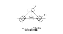
ところで、上記画像処理装置1では、撮影装置2を一定の速度で動かしながら被写体を連続的に撮影することにより、視差画像列を得たが、このような視差画像列の撮影方法には、具体的には、panning方式、rotating方式、re-centering方式等がある。
【0043】
panning方式では、図3に示すように、常に被写体10の中心を向くようにカメラ11の方向を変化させながら、カメラ11を直線上のレールに沿って平行に動かして、異なる位置から被写体10を多数撮影する。すなわち、panning方式で視差画像列を撮影する際は、カメラ11を被写体10の中心に向けてパンさせながら、被写体10に向けたカメラ11を平行に動かし、この間において多数の画像を撮影する。
【0044】
rotating方式では、図4に示すように、被写体10の中心に向けたカメラ11を円弧状に移動させて視差画像列を撮影する。rotating方式も、カメラ11が常に被写体10の中心を向くので、画像の有効解像度を高めることができる。
【0045】
re-centering方式では、図5に示すように、カメラ11を直線上のレールに沿って平行に移動させて、異なる位置から被写体10を多数撮影するとともに、その撮影時に、被写体10の像が画面の中心に常に位置するように、撮影する位置に合わせてカメラ11のレンズ12を移動させる。すなわち、re-centering方式では、カメラ11のレンズ12と撮像面13の相対的位置関係を、カメラ本体の動きと合わせて変えることによって、被写体10を常に撮像面13の中心に投影して撮影を行う。
【0046】
そして、本発明を適用した画像処理装置1で視差画像列を撮影する際は、これらいずれの方式を用いても良い。
【0047】
ところで、以上のような画像処理装置1で新たに作成された視差画像列の映像信号は、上述したように、例えば、ホログラフィックステレオグラム作成システムに送られ、ホログラフィックステレオグラムの作成に用いられる。そこで、以下、ホログラフィックステレオグラムを作成するホログラフィックステレオグラム作成システムについて、具体的な例を挙げて説明する。
【0048】
なお、以下に説明するホログラフィックステレオグラム作成システムは、物体光と参照光との干渉縞が記録されたフィルム状のホログラム用記録媒体をそのままホログラフィックステレオグラムとして出力する。このように物体光と参照光との干渉縞がホログラム用記録媒体に直接記録されてなるホログラフィックステレオグラムは、一般に、ワンステップホログラフィックステレオグラムと称される。
【0049】
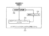
このようにワンステップホログラフィックステレオグラムを作成するホログラフィックステレオグラム作成システムの一構成例を図6に示す。
【0050】
このホログラフィックステレオグラム作成システム23は、ホログラフィックステレオグラム作成システム全体の制御を行う制御用コンピュータ24と、ホログラフィックステレオグラム作成用の光学系を有するホログラフィックステレオグラムプリンタ25と、ホログラフィックステレオグラム作成時に露光用画像の映像信号をホログラフィックステレオグラムプリンタ25に供給する映像信号供給装置26とを備える。
【0051】
映像信号処理装置26は、上記画像処理装置1から視差画像列の映像信号を受け取り、当該視差画像列に対して必要に応じて視点変換処理やキーストン歪み補正処理などを施して、映像信号を1フレーム毎にホログラフィックステレオグラムプリンタ25に送る。また、映像信号処理装置26は、ホログラフィックステレオグラムプリンタ25に1フレーム分の映像信号を送る毎に、1フレーム分の映像信号を送ったことを示すタイミング信号を制御用コンピュータ24に送出する。
【0052】
制御用コンピュータ24は、映像信号処理装置26からのタイミング信号に基づいてホログラフィックステレオグラムプリンタ25を駆動する。そして、ホログラフィックステレオグラムプリンタ25は、制御用コンピュータ24による制御に基づき、映像信号処理装置26から供給された映像信号に基づく画像を、ホログラフィックステレオグラムプリンタ25の内部にセットされたホログラム用記録媒体に、短冊状の要素ホログラムとして順次記録する。
【0053】
このとき、制御用コンピュータ24は、後述するように、ホログラフィックステレオグラムプリンタ25に設けられた露光用シャッタ及び記録媒体送り機構等の制御を行う。すなわち、制御用コンピュータ24は、ホログラフィックステレオグラムプリンタ25に制御信号を送出して、露光用シャッタの開閉や、記録媒体送り機構によるホログラム用記録媒体の送り動作などを制御する。
【0054】
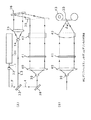
上記ホログラフィックステレオグラムプリンタ25について、図7を参照して更に詳細に説明する。なお、図7(A)は、ホログラフィックステレオグラムプリンタ25の全体の光学系を上から見た図であり、図7(B)は、ホログラフィックステレオグラムプリンタ25の光学系の物体光用の部分を横から見た図である。
【0055】
ホログラフィックステレオグラムプリンタ25は、図7(A)に示すように、所定の波長のレーザ光を出射するレーザ光源31と、レーザ光源31からのレーザ光L1の光軸上に配された露光用シャッタ32及びハーフミラー33とを備えている。
【0056】
露光用シャッタ32は、制御用コンピュータ24によって制御され、ホログラム用記録媒体30を露光しないときには閉じられ、ホログラム用記録媒体30を露光するときに開かれる。また、ハーフミラー33は、露光用シャッタ32を通過してきたレーザ光L2を、参照光と物体光とに分離するためのものであり、ハーフミラー33によって反射された光L3が参照光となり、ハーフミラー33を透過した光L4が物体光となる。
【0057】
ハーフミラー33によって反射された光L3の光軸上には、参照光用の光学系として、シリンドリカルレンズ34と、参照光を平行光とするためのコリメータレンズ35と、コリメータレンズ35によって平行光とされた光を反射する全反射ミラー36とがこの順に配置されている。
【0058】
そして、ハーフミラー33によって反射された光は、先ず、シリンドリカルレンズ34によって発散光とされ、次に、コリメータレンズ35によって平行光とされる。その後、全反射ミラー36によって反射され、ホログラム用記録媒体30に入射する。
【0059】
一方、ハーフミラー33を透過した光L4の光軸上には、図7(A)及び図7(B)に示すように、物体光用の光学系として、ハーフミラー33からの透過光を反射する全反射ミラー38と、凸レンズとピンホールを組み合わせたスペーシャルフィルタ39と、物体光を平行とするためのコリメータレンズ40と、記録対象の画像を表示する表示装置41と、物体光をホログラム用記録媒体30上に集光させるシリンドリカルレンズ42とがこの順に配置されている。
【0060】
そして、ハーフミラー33を透過した光L4は、全反射ミラー38によって反射された後、スペーシャルフィルタ39によって点光源からの拡散光とされ、次に、コリメータレンズ40によって平行光とされ、その後、表示装置41に入射する。ここで、表示装置41は、例えば液晶パネルからなる透過型の画像表示装置であり、映像信号処理装置26から供給された映像信号に基づく画像を表示する。そして、表示装置41を透過した光は、表示装置41に表示された画像に応じて変調された後、シリンドリカルレンズ42に入射する。
【0061】
そして、表示装置41を透過した光は、シリンドリカルレンズ42により、所定の集光角θeにて集束され、この集束光が物体光としてホログラム用記録媒体30に入射する。すなわち、このホログラフィックステレオグラムプリンタ25では、表示装置41からの投影光が短冊状の物体光としてホログラム用記録媒体30に入射する。
【0062】
ここで、参照光及び物体光は、参照光がホログラム用記録媒体30の一方の面に入射し、物体光がホログラム用記録媒体30の他方の面に入射するようにする。すなわち、ホログラム用記録媒体30の一方の面に、参照光を所定の入射角度にて入射させるとともに、ホログラム用記録媒体30の他方の面に、物体光をホログラム用記録媒体30に対して光軸がほぼ垂直となるように入射させる。これにより、参照光と物体光とがホログラム用記録媒体30上において干渉し、当該干渉によって生じる干渉縞が、ホログラム用記録媒体30に屈折率の変化として記録される。
【0063】
また、このホログラフィックステレオグラムプリンタ25は、制御用コンピュータ24の制御のもとに、ホログラム用記録媒体30を間欠送りし得る記録媒体送り機構43を備えている。この記録媒体送り機構43は、記録媒体送り機構43に所定の状態でセットされたホログラム用記録媒体30に対して、映像信号処理装置26から供給された映像信号に基づく1つの画像が1つの要素ホログラムとして記録される毎に、制御用コンピュータ24からの制御信号に基づいて、ホログラム用記録媒体30を1要素ホログラム分だけ間欠送りする。これにより、映像信号処理装置26から供給された映像信号に基づく画像が、要素ホログラムとして、ホログラム用記録媒体30に横方向に連続するように順次記録される。
【0064】
なお、上記ホログラフィックステレオグラムプリンタ25において、ハーフミラー33によって反射されホログラム用記録媒体30に入射する参照光の光路長と、ハーフミラー33を透過し表示装置41を介してホログラム用記録媒体30に入射する物体光の光路長とは、ほぼ同じ長さとすることが好ましい。これにより、参照光と物体光との干渉性が高まり、ホログラフィックステレオグラムの画質が向上する。
【0065】
また、上記ホログラフィックステレオグラムプリンタ25において、ホログラフィックステレオグラムの画質を向上させるために、物体光の光路上に拡散板を配してもよい。物体光の光路上に拡散板を配することにより、物体光に含まれるノイズ成分が分散され、また、ホログラム用記録媒体30に入射する物体光の光強度分布がより均一になり、作成されるホログラフィックステレオグラムの画質が向上する。
【0066】
ただし、このように拡散板を配するときは、拡散板とホログラム用記録媒体30の間に、要素ホログラムの形状に対応した短冊状の開口部が形成されたマスクを配することが好ましい。このようにマスクを配することにより、拡散板によって拡散された物体光のうち、余分な部分がマスクによって遮られることとなり、より高画質なホログラフィックステレオグラムを作成することが可能となる。
【0067】
また、上記ホログラフィックステレオグラムプリンタ25では、ホログラフィックステレオグラムに縦方向の視野角を持たせるために、物体光の光路上に、物体光を縦方向に拡散させる一次元拡散板を配してもよい。物体光の光路上に一次元拡散板を配することにより、物体光が縦方向(要素ホログラムの長軸方向)に拡散され、これにより、作成されるホログラフィックステレオグラムは縦方向の視野角を有することとなる。
【0068】
ただし、このように一次元拡散板を配するときは、ホログラム用記録媒体30と一次元拡散板の間に、微細な簾状の格子を有するルーバーフィルムを配することが好ましい。このようにルーバーフィルムを配することにより、ホログラム用記録媒体30を透過した参照光が一次元拡散板によって反射されて、再びホログラム用記録媒体30に入射するのを防ぐことができる。
【0069】
つぎに、上記ホログラフィックステレオグラム作成システム23の動作について説明する。
【0070】
ホログラフィックステレオグラムを作成する際、映像信号処理装置26は、ホログラフィックステレオグラムプリンタ25の表示装置41に映像信号を送出し、当該映像信号に基づく露光用画像を表示装置41に表示させる。このとき、映像信号処理装置26は、映像信号をホログラフィックステレオグラムプリンタ25の表示装置41に送出したことを示すタイミング信号を、制御用コンピュータ24に送出する。
【0071】
そして、上記タイミング信号を受け取った制御用コンピュータ24は、露光用シャッタ32に制御信号を送出し、所定時間だけ露光用シャッタ32を開放させる。これにより、ホログラム用記録媒体30が露光される。
【0072】
このとき、レーザ光源31から出射され露光用シャッタ32を透過したレーザ光L2のうち、ハーフミラー33によって反射された光L3が、参照光としてホログラム用記録媒体30に入射する。また、ハーフミラー33を透過した光L4が、表示装置41に表示された画像が投影された投影光となり、当該投影光が物体光としてホログラム用記録媒体30に入射する。これにより、表示装置41に表示された露光用画像が、ホログラム用記録媒体30に短冊状の要素ホログラムとして記録される。
【0073】
そして、ホログラム用記録媒体30への1画像の記録が終了すると、次いで、制御用コンピュータ24は、記録媒体送り機構43に制御信号を送出し、ホログラム用記録媒体30を1要素ホログラム分だけ送らせる。
【0074】
以上の動作を、表示装置41に表示させる露光用画像を視差画像列順に順次変えて繰り返す。これにより、映像信号処理装置26から供給された映像信号に基づく露光用画像が、ホログラム用記録媒体30に短冊状の要素ホログラムとして順次記録される。
【0075】
なお、このように要素ホログラムを順次記録する際、記録媒体送り機構43でホログラム用記録媒体を送ったときに、ホログラム用記録媒体30が若干振動する場合がある。このような場合は、ホログラム用記録媒体30を送る毎に振動が収まるのを待ち、振動が収まった後に要素ホログラムを記録するようにする。
【0076】
以上のように、このホログラフィックステレオグラム作成システム23では、映像信号処理装置26からホログラフィックステレオグラムプリンタ25に映像信号を順次供給し、それらの映像信号に基づく露光用画像を表示装置41に順次表示し、各画像毎に露光用シャッタ32を開放し、各画像をそれぞれ短冊状の要素ホログラムとしてホログラム用記録媒体30に順次記録する。このとき、ホログラム用記録媒体30は、1画像毎に1要素ホログラム分だけ送られるので、各要素ホログラムは、横方向に連続して並ぶこととなる。これにより、横方向の視差情報を含む複数の画像からなる視差画像列が、横方向に連続した複数の要素ホログラムとしてホログラム用記録媒体30に記録され、横方向の視差を有するホログラフィックステレオグラムが得られる。
【0077】
なお、以上の説明では、本発明を適用した画像処理装置1と、ホログラフィックステレオグラム作成システム23とがそれぞれ独立しているものとして説明したが、これらは一体とされていても良い。これらを一体とする場合には、上記画像処理装置1の制御用コンピュータ7が、上記ホログラフィックステレオグラム作成システム23の制御コンピュータ24を兼ねるようにしても良いし、また、上記画像処理装置1のクロマキー合成装置6と、上記ホログラフィックステレオグラム作成システム23の映像信号処理装置26とを、一つの映像処理装置としてまとめてしまっても良い。
【0078】
【発明の効果】
以上詳細に説明したように、本発明では、複数組の視差画像列について、それらの視差画像列を構成する画像の枚数を一致させ、その後、画像の枚数が一致させられた視差画像列同士を合成して、新たな視差画像列を作成するようにしている。また、この複数組の視差画像列は、背景の視差画像列とこの背景の視差画像列を構成する画像の枚数よりも少ない枚数からなる動的被写体の視差画像列であり、動的被写体の視差画像列を構成する画像の枚数を背景の視差画像列を構成する画像の枚数に一致させるようにしている。これにより、枚数の異なる複数組の視差画像列から、立体画像のもととなる一組の視差画像列を作成することが可能となっている。
【0079】
すなわち、本発明によれば、視差画像列の枚数を変えて被写体の撮影を行うようなことが可能であり、被写体に合わせて最適な枚数の視差画像列を撮影するようにすることができる。すなわち、本発明によれば、必要以上の撮影を省くことが可能となり、視差画像列の撮影に要する時間を短縮することが出来る。換言すれば、本発明によれば、視差画像列の撮影に要する時間を短縮しつつ、当該視差画像列をもとに得られる立体画像の画質を維持することが可能となる。
【図面の簡単な説明】
【図1】本発明を適用した画像処理装置の一構成例を示すブロック図である。
【図2】上記画像処理装置で新たな視差画像列の映像信号を作成するときの処理の流れを示す図である。
【図3】 panning方式による視差画像列の撮影方法を示す図である。
【図4】 rotating方式による視差画像列の撮影方法を示す図である。
【図5】 re-centering方式による視差画像列の撮影方法を示す図である。
【図6】ホログラフィックステレオグラム作成システムの一構成例を示すブロック図である。
【図7】ホログラフィックステレオグラムプリンタの光学系の一構成例を示す図である。
【図8】ホログラフィックステレオグラムの作成方法を模式的に示す図である。
【符号の説明】
1 画像処理装置、2 撮影装置、 3 映像信号処理装置、 4 映像信号記録再生装置、 5 映像信号再生装置、 6 クロマキー合成装置、 7 制御用コンピュータ[0001]
BACKGROUND OF THE INVENTION
The present invention relates to an image processing apparatus and an image processing method for creating a parallax image sequence used for creating a holographic stereogram.
[0002]
[Prior art]
A parallax image sequence including a plurality of images having parallax information is used, for example, to create a holographic stereogram that displays a stereoscopic image. The holographic stereogram uses a parallax image sequence composed of a large number of images obtained by sequentially photographing a subject from different viewpoints as an original image, and these are used as a strip-shaped or dot-shaped element hologram on a single hologram recording medium. It is created by recording sequentially.
[0003]
For example, when creating a holographic stereogram having parallax information only in the horizontal direction, the parallax information in the horizontal direction is first obtained by sequentially photographing the
[0004]
In this holographic stereogram, when the holographic stereogram is viewed from one position with one eye, a two-dimensional image that is a collection of image information of a part of each element hologram can be seen, and the position of the eye is horizontally oriented. If it is moved, a two-dimensional image that is a collection of image information of another part of each element hologram can be seen. Therefore, when the observer views the holographic stereogram with both eyes, the positions of the left and right eyes are slightly different in the horizontal direction, so that the two-dimensional images captured in each are slightly different. Thereby, the observer feels parallax and the stereoscopic image is recognized. Such a holographic stereogram is described in, for example, Japanese Patent Laid-Open No. 10-20756.
[0005]
When shooting a parallax image sequence as an original image of such a holographic stereogram, the subject is sequentially shot from different directions while moving the shooting device. Thereby, a parallax image sequence including a plurality of images having parallax information is obtained. Specifically, for example, a video camera that captures 30 frames per second is used as a photographing device, and the subject is continuously photographed while moving the video camera at a constant speed. At this time, for example, if the subject is photographed for 7.5 seconds, 225 frames are photographed, and as a result, a parallax image sequence composed of 225 images having different viewpoints with respect to the subject is obtained.
[0006]
[Problems to be solved by the invention]
Since the parallax image sequence is obtained by sequentially shooting the subject from different directions, it takes a certain amount of time to shoot the parallax image sequence. If the subject is a still life, there is not much problem even if the time required to shoot the parallax image sequence is somewhat long. However, when the subject is not a still life (for example, when the subject is a person), the subject may move during photographing, so it is desirable to shorten the time required for photographing the parallax image sequence as much as possible. .
[0007]
However, when the number of images that can be captured per unit time is determined, if the time required for capturing the parallax image sequence is shortened, the number of images constituting the parallax image sequence is reduced. When the number of images constituting the parallax image sequence is reduced, the image quality of the stereoscopic image obtained based on the parallax image sequence is degraded.
[0008]
That is, the time required to shoot a parallax image sequence and the quality of a stereoscopic image obtained based on the parallax image sequence are in a trade-off relationship, and conventionally, the time required to shoot a parallax image sequence is reduced. Therefore, it has been difficult to sufficiently maintain the quality of the stereoscopic image obtained based on the parallax image sequence.
[0009]
The present invention has been proposed in view of the conventional situation as described above, and maintains the image quality of a stereoscopic image obtained based on the parallax image sequence while reducing the time required to shoot the parallax image sequence. It is an object of the present invention to provide an image processing apparatus and an image processing method that can be performed.
[0010]
[Means for Solving the Problems]
An image processing apparatus according to the present invention creates a parallax image sequence composed of a plurality of images having parallax information.A parallax image sequence of the dynamic subject and a parallax image sequence of the background, and a number of images constituting the parallax image sequence of the background and the parallax image sequence of the background photographed by the photographing unit. The image number adjusting means for matching the number of images constituting the parallax image sequence with the parallax image sequence of the dynamic subject having a small number of images, and the parallax image sequences in which the number of images are matched by the image number adjusting means are combined. And an image synthesis means for generating a new parallax image sequence. The number-of-images adjusting means adds the number of images constituting the parallax image sequence of the dynamic subject to the image based on the image constituting the parallax image sequence of the dynamic subject to constitute the background parallax image sequence. It is characterized by matching the number of images.
[0011]
In addition, the image processing method according to the present invention provides image processing for creating a parallax image sequence including a plurality of images having parallax information.MethodInA shooting process for shooting a parallax image sequence of a dynamic subject and a parallax image sequence of a background, and a number smaller than the number of images constituting the parallax image sequence of the background and the parallax image sequence of the background shot by the shooting process. An image number adjustment step for matching the number of images constituting the parallax image sequence with the parallax image sequence of the dynamic subject, and a parallax image sequence in which the number of images is matched by the image number adjustment step are synthesized, And an image composition step for generating a new parallax image sequence. The number-of-images adjusting step adds the number of images constituting the parallax image sequence of the dynamic subject to the image based on the image constituting the parallax image sequence of the dynamic subject to form the background parallax image sequence. It is characterized by matching the number of images.
[0012]
In general, when a stereoscopic image is reproduced based on a parallax image sequence, the number of original images necessary to maintain the quality of a reproduced image varies depending on the position where the reproduced image is localized. For example, when a holographic stereogram is created by sequentially recording each image constituting a parallax image sequence as an element hologram on a hologram recording medium, a reproduced image is localized deeper than the hologram recording medium surface, and hologram recording The number of original images required to maintain the same image quality differs between when the reproduced image is localized on the medium surface and when the reproduced image is localized before the hologram recording medium surface. This is because there is a difference in image correlation between the viewpoints depending on the position where the reproduced image is localized.
[0013]
Therefore, if the subject is photographed by changing the number of parallax image sequences according to the position where the reproduced image is localized, it is possible to shoot the optimum number of parallax image sequences according to the position where the reproduced image is localized. . In other words, it is possible to omit more than necessary shooting, and the time required for shooting the parallax image sequence can be shortened. However, a three-dimensional image cannot be reproduced with a plurality of sets of parallax image sequences obtained in this way.
[0014]
Therefore, in the present invention, first,A parallax image sequence of a dynamic subject comprising a background parallax image sequence photographed by the imaging means and a number smaller than the number of images constituting the background parallax image sequence;The number of images constituting the parallax image sequence is made to coincide, and then the parallax image sequences with the matched number of images are synthesized to create a new parallax image sequence. This makes the number of sheets differentA parallax image sequence of a dynamic subject and a parallax image sequence of a backgroundThus, it is possible to create a set of parallax image sequences that are the basis of a stereoscopic image.
[0015]
DETAILED DESCRIPTION OF THE INVENTION
Hereinafter, embodiments of the present invention will be described in detail with reference to the drawings. In the following description, an example in which the present invention is applied to a holographic stereogram creation system will be described. However, the image processing apparatus and the image processing method according to the present invention are widely applicable in fields where a parallax image sequence is required. It is. For example, a parallax image sequence is also required when displaying a stereoscopic image on a display device using parallax, and the image processing apparatus and the image processing method according to the present invention are also applicable to such a case. It is.
[0016]
A configuration example of an image processing apparatus to which the present invention is applied is shown in FIG. The
[0017]
The photographing
[0018]
The video
[0019]
The video signal recording / reproducing apparatus 4 is for recording a video signal on a recording medium or reproducing a video signal recorded on the recording medium. Here, for example, an optical disk, a magnetic disk, a magnetic tape, or a semiconductor memory is used as the recording medium. The video signal recording / reproducing apparatus 4 receives the video signal in a predetermined format by the video
[0020]
The video signal recording / reproducing apparatus 4 repeatedly outputs the video signal of the same frame according to an instruction from the control computer 7 as necessary when reproducing the video signal from the recording medium. In other words, the video signal recording / reproducing apparatus 4 increases the number of frames of the video signal to be output from the number of frames of the video signal reproduced from the recording medium in accordance with an instruction from the control computer 7 as necessary. To do.
[0021]
For example, it is assumed that the photographing
[0022]
The video
[0023]
The chroma
[0024]
Next, creation of a parallax image sequence by the
[0025]
Here, a parallax image based on a holographic stereogram in which a reproduced image of a person is localized on the hologram recording medium surface and a reproduced image serving as a background is localized behind the hologram recording medium surface. Assume that a video signal of a column is created. The background parallax image sequence is taken in advance, and the video signal is assumed to be a video signal of 7.5 seconds, that is, 225 frames, at a video rate of 30 frames per second.
[0026]
The parallax image sequence is obtained by shooting the subject from different viewpoints, but in the case of a subject that is localized on the surface of the hologram recording medium, the correlation between the images between the viewpoints is large, and even if the viewpoint position changes, the image There is little change. On the other hand, in the case of a subject that is located deeper than the hologram recording medium surface, the correlation between images between the viewpoints is small, and the image changes greatly when the viewpoint position changes.
[0027]
Therefore, the number of parallax image sequences obtained by photographing a subject that is localized on the hologram recording medium surface may be smaller than the number of parallax image sequences obtained by photographing a subject that is located deeper than the hologram recording medium surface. In other words, for a subject whose reproduced image is localized on the hologram recording medium surface, the image quality of the reproduced image localized on the hologram recording medium surface and the hologram recording medium surface can be reduced even if the number of parallax image rows is reduced. In addition, the image quality of the reproduced image localized in the back can be set to the same level.
[0028]
Therefore, in this example, a subject (that is, a person) whose reproduced image is localized on the hologram recording medium surface is photographed for 3 seconds, that is, 90 frames at a video rate of 30 frames per second. .
[0029]
That is, first, as shown in step S1 of FIG. 2, a person who is a subject whose reproduced image is localized on the hologram recording medium surface is subjected to 3 seconds at a video rate of 30 frames per second by the photographing
[0030]
The video signal recorded on the recording medium as described above is then reproduced by the video signal recording / reproducing apparatus 4 as shown in step S3. At this time, the video signal recording / reproducing apparatus 4 reproduces the video signal so that the number of frames of the parallax image sequence in which the person is captured is the same as the number of frames of the video signal in the parallax image sequence in which the background is captured. In other words, the video signal recording / reproducing apparatus 4 makes the number of images constituting the parallax image sequence showing a person coincide with the number of images constituting the parallax image sequence showing the background.
[0031]
In this example, the background photographing time is 7.5 seconds, and the total number of frames is 225 frames. Therefore, the video signal recording / reproducing device 4 repeatedly outputs each frame two or three times when reproducing the video signal of the parallax image sequence obtained by photographing a person from the recording medium, so that 225 frames as a whole are output. Output video signal. Simultaneously with the reproduction of the video signal by the video signal recording / reproducing apparatus 4, as shown in step S4, the video
[0032]
Then, the video signal reproduced by the video signal recording / reproducing device 4 (that is, the video signal of the parallax image sequence obtained by photographing a person) and the video signal reproduced by the video signal reproducing device 5 (ie, the parallax image sequence obtained by photographing the background). Video signal) is input to the chroma
[0033]
Then, the chroma
[0034]
At this time, the number of frames of the video signal reproduced by the video signal recording / reproducing apparatus 4 (that is, the number of parallax image sequences obtained by photographing a person) and the number of frames of the video signal reproduced by the video signal reproducing apparatus 5 (that is, the background) The number of captured parallax image sequences) is the same, and the chroma
[0035]
Then, the video signal of the newly created parallax image sequence is output from the chroma
[0036]
As described above, when the
[0037]
In particular, as in this example, the image processing to which the present invention is applied is used when the reproduced image of the background is localized deep inside the hologram recording medium surface and the reproduced image of a person is localized on the hologram recording medium surface. The
[0038]
In the
[0039]
However, the video signal recording / reproducing apparatus 4 does not add an image to the parallax image sequence by simply outputting the frame repeatedly, but creates an interpolated image from the images constituting the parallax image sequence, You may make it add to the original parallax image sequence. That is, the number of images constituting each parallax image sequence may be matched by adding an interpolation image newly generated by interpolation processing from previous and subsequent images to the parallax image sequence having a small number of images. . In this way, if the interpolation image is added to the original parallax image sequence, the parallax in which the image continuously and smoothly changes as the viewpoint moves even if the number of images constituting the parallax image sequence is increased. An image sequence can be obtained.
[0040]
In the
[0041]
In the above example, the background parallax image sequence is captured in advance, but it is needless to say that the background parallax image sequence may be captured by the
[0042]
By the way, in the
[0043]
In the panning method, as shown in FIG. 3, while changing the direction of the
[0044]
In the rotating method, as shown in FIG. 4, the parallax image sequence is photographed by moving the
[0045]
In the re-centering method, as shown in FIG. 5, the
[0046]
And when imaging | photography a parallax image sequence with the
[0047]
By the way, as described above, the video signal of the parallax image sequence newly created by the
[0048]
The holographic stereogram creation system described below outputs a film-like hologram recording medium on which interference fringes between object light and reference light are recorded as it is as a holographic stereogram. A holographic stereogram in which the interference fringes between the object beam and the reference beam are directly recorded on the hologram recording medium is generally called a one-step holographic stereogram.
[0049]
FIG. 6 shows a configuration example of a holographic stereogram creation system for creating a one-step holographic stereogram in this way.
[0050]
The holographic
[0051]
The video
[0052]
The
[0053]
At this time, as will be described later, the
[0054]
The
[0055]
The
[0056]
The
[0057]
On the optical axis of the light L3 reflected by the
[0058]
The light reflected by the
[0059]
On the other hand, on the optical axis of the light L4 transmitted through the
[0060]
Then, the light L4 transmitted through the
[0061]
And the light which permeate | transmitted the
[0062]
Here, the reference light and the object light are incident on one surface of the
[0063]
The
[0064]
In the
[0065]
Further, in the
[0066]
However, when the diffusion plate is arranged in this way, it is preferable to arrange a mask having a strip-shaped opening corresponding to the shape of the element hologram between the diffusion plate and the
[0067]
In the
[0068]
However, when the one-dimensional diffusion plate is arranged in this way, it is preferable to arrange a louver film having a fine bowl-shaped lattice between the
[0069]
Next, the operation of the holographic
[0070]
When creating the holographic stereogram, the video
[0071]
Upon receiving the timing signal, the
[0072]
At this time, among the laser light L2 emitted from the laser light source 31 and transmitted through the
[0073]
When the recording of one image on the
[0074]
The above operation is repeated by sequentially changing the exposure image displayed on the
[0075]
When the element holograms are sequentially recorded in this manner, the
[0076]
As described above, in this holographic
[0077]
In the above description, the
[0078]
【The invention's effect】
As described above in detail, in the present invention, for a plurality of sets of parallax image sequences, the number of images constituting the parallax image sequence is matched, and then the parallax image sequences whose images are matched are matched. A new parallax image sequence is created by combining them.Further, the plurality of sets of parallax image sequences are parallax image sequences of a dynamic subject including a parallax image sequence of a background and a number smaller than the number of images constituting the parallax image sequence of the background. The number of images constituting the image sequence is made to coincide with the number of images constituting the background parallax image sequence.Thereby, it is possible to create a set of parallax image sequences as a basis of a stereoscopic image from a plurality of sets of parallax image sequences having different numbers.
[0079]
That is, according to the present invention, it is possible to shoot a subject by changing the number of parallax image sequences, and it is possible to shoot an optimal number of parallax image sequences in accordance with the subject. That is, according to the present invention, it is possible to omit more than necessary shooting, and it is possible to reduce the time required for shooting a parallax image sequence. In other words, according to the present invention, it is possible to maintain the image quality of a stereoscopic image obtained based on the parallax image sequence while reducing the time required to shoot the parallax image sequence.
[Brief description of the drawings]
FIG. 1 is a block diagram illustrating a configuration example of an image processing apparatus to which the present invention is applied.
FIG. 2 is a diagram showing a flow of processing when a video signal of a new parallax image sequence is created by the image processing apparatus.
FIG. 3 is a diagram illustrating a method of capturing a parallax image sequence by a panning method.
FIG. 4 is a diagram illustrating a method of capturing a parallax image sequence by a rotating method.
FIG. 5 is a diagram illustrating a method of capturing a parallax image sequence by a re-centering method.
FIG. 6 is a block diagram illustrating a configuration example of a holographic stereogram creation system.
FIG. 7 is a diagram illustrating a configuration example of an optical system of a holographic stereogram printer.
FIG. 8 is a diagram schematically showing a method for creating a holographic stereogram.
[Explanation of symbols]
DESCRIPTION OF
Claims (8)
動的被写体の視差画像列と背景の視差画像列とを撮影する撮影手段と、
上記撮影手段により撮影された、上記背景の視差画像列と該背景の視差画像列を構成する画像の枚数よりも少ない枚数からなる動的被写体の視差画像列との視差画像列を構成する画像の枚数を一致させる画像枚数調整手段と、
上記画像枚数調整手段により上記画像の枚数が一致させられた視差画像列同士を合成して、新たな視差画像列を生成する画像合成手段とを備え、
上記画像枚数調整手段は、上記動的被写体の視差画像列を構成する画像の枚数を、該動的被写体の視差画像列を構成する画像に基づく画像を追加して、上記背景の視差画像列を構成する画像の枚数に一致させることを特徴とする画像処理装置。 An image processing apparatus for generating a parallax image string comprising a plurality of images having parallax information,
Photographing means for photographing the parallax image sequence of the dynamic subject and the parallax image sequence of the background;
The images constituting the parallax image sequence of the background parallax image sequence and the parallax image sequence of the dynamic subject having a smaller number than the number of images constituting the parallax image sequence of the background photographed by the photographing unit. Image number adjusting means for matching the number of images;
By combining the parallax image string each other are matched the number of the image by the image number adjustment means, and an image synthesizing means for generating a new parallax image string,
The image number adjusting means adds the number of images constituting the parallax image sequence of the dynamic subject to the image based on the image constituting the parallax image sequence of the dynamic subject, and An image processing apparatus characterized by matching the number of images to be configured .
動的被写体の視差画像列と背景の視差画像列とを撮影する撮影工程と、
上記撮影工程により撮影された、上記背景の視差画像列と該背景の視差画像列を構成する画像の枚数より少ない枚数からなる動的被写体の視差画像列との視差画像列を構成する画像の枚数を一致させる画像枚数調整工程と、
上記画像枚数調整工程により上記画像の枚数が一致させられた視差画像列同士を合成して、新たな視差画像列を生成する画像合成工程とを有し、
上記画像枚数調整工程は、上記動的被写体の視差画像列を構成する画像の枚数を、該動的被写体の視差画像列を構成する画像に基づく画像を追加して、上記背景の視差画像列を構成する画像の枚数に一致させることを特徴とする画像処理方法。In an image processing method for creating a parallax image sequence composed of a plurality of images having parallax information,
A shooting step of shooting a parallax image sequence of a dynamic subject and a parallax image sequence of a background;
The number of images constituting the parallax image sequence of the background parallax image sequence and the parallax image sequence of the dynamic subject having a smaller number than the number of images constituting the background parallax image sequence. an image number adjustment step of Ru to match the,
An image synthesis step of generating a new parallax image sequence by synthesizing the parallax image sequences in which the number of images is matched in the image number adjustment step ,
In the image number adjustment step, the number of images constituting the parallax image sequence of the dynamic subject is added to the image based on the image constituting the parallax image sequence of the dynamic subject, and the background parallax image sequence is obtained. An image processing method characterized by matching the number of images to be configured .
Priority Applications (2)
| Application Number | Priority Date | Filing Date | Title |
|---|---|---|---|
| JP24640898A JP4075151B2 (en) | 1998-08-31 | 1998-08-31 | Image processing apparatus and image processing method |
| US09/386,195 US6614467B1 (en) | 1998-08-31 | 1999-08-30 | Image processing method and apparatus |
Applications Claiming Priority (1)
| Application Number | Priority Date | Filing Date | Title |
|---|---|---|---|
| JP24640898A JP4075151B2 (en) | 1998-08-31 | 1998-08-31 | Image processing apparatus and image processing method |
Publications (2)
| Publication Number | Publication Date |
|---|---|
| JP2000078613A JP2000078613A (en) | 2000-03-14 |
| JP4075151B2 true JP4075151B2 (en) | 2008-04-16 |
Family
ID=17148059
Family Applications (1)
| Application Number | Title | Priority Date | Filing Date |
|---|---|---|---|
| JP24640898A Expired - Fee Related JP4075151B2 (en) | 1998-08-31 | 1998-08-31 | Image processing apparatus and image processing method |
Country Status (2)
| Country | Link |
|---|---|
| US (1) | US6614467B1 (en) |
| JP (1) | JP4075151B2 (en) |
Families Citing this family (1)
| Publication number | Priority date | Publication date | Assignee | Title |
|---|---|---|---|---|
| JP4937390B2 (en) * | 2010-08-24 | 2012-05-23 | 株式会社東芝 | 3D image display device and 3D image glasses |
Family Cites Families (16)
| Publication number | Priority date | Publication date | Assignee | Title |
|---|---|---|---|---|
| JPS59182688A (en) * | 1983-03-31 | 1984-10-17 | Toshiba Corp | Stereoscopic processor |
| JP2869072B2 (en) * | 1988-08-30 | 1999-03-10 | 大日本印刷株式会社 | How to make holographic stereogram |
| US6392689B1 (en) * | 1991-02-21 | 2002-05-21 | Eugene Dolgoff | System for displaying moving images pseudostereoscopically |
| JP2882082B2 (en) * | 1991-03-28 | 1999-04-12 | 凸版印刷株式会社 | Holographic stereogram and method for producing the same |
| JP2746790B2 (en) * | 1992-03-02 | 1998-05-06 | 富士写真フイルム株式会社 | Stereoscopic image recording method and stereoscopic image recording apparatus |
| JP2842735B2 (en) * | 1992-07-20 | 1999-01-06 | 沖電気工業株式会社 | Multi-viewpoint three-dimensional image input device, image synthesizing device, and image output device thereof |
| JP2941139B2 (en) * | 1993-03-11 | 1999-08-25 | 凸版印刷株式会社 | Parallax image creation method and device |
| JPH0749944A (en) * | 1993-08-04 | 1995-02-21 | Canon Inc | Method and device for image processing |
| JPH07311857A (en) * | 1994-05-16 | 1995-11-28 | Fujitsu Ltd | Picture compositing and display device and simulation system |
| JP3539002B2 (en) * | 1995-10-06 | 2004-06-14 | 凸版印刷株式会社 | Stereogram |
| JP3328478B2 (en) * | 1995-10-18 | 2002-09-24 | 日本電信電話株式会社 | Camera system |
| JP3704875B2 (en) * | 1996-06-21 | 2005-10-12 | ソニー株式会社 | Image recording method and apparatus |
| US6108440A (en) * | 1996-06-28 | 2000-08-22 | Sony Corporation | Image data converting method |
| JPH1078742A (en) * | 1996-09-04 | 1998-03-24 | Sony Corp | Parallactic picture line generating method |
| US6123733A (en) * | 1996-11-27 | 2000-09-26 | Voxel, Inc. | Method and apparatus for rapidly evaluating digital data processing parameters |
| JP3709659B2 (en) * | 1997-06-11 | 2005-10-26 | ソニー株式会社 | Image recording apparatus and image recording method |
-
1998
- 1998-08-31 JP JP24640898A patent/JP4075151B2/en not_active Expired - Fee Related
-
1999
- 1999-08-30 US US09/386,195 patent/US6614467B1/en not_active Expired - Fee Related
Also Published As
| Publication number | Publication date |
|---|---|
| JP2000078613A (en) | 2000-03-14 |
| US6614467B1 (en) | 2003-09-02 |
Similar Documents
| Publication | Publication Date | Title |
|---|---|---|
| US7327389B2 (en) | Apparatus and method for photographing three-dimensional image, apparatus and method for displaying three-dimensional image, and apparatus and method for converting three-dimensional image display position | |
| JP3744559B2 (en) | Stereo camera, stereo display, and stereo video system | |
| KR100855287B1 (en) | Image-reproducing apparatus and image-reproducing method | |
| JP4066488B2 (en) | Image data generation apparatus and image data generation method | |
| JP2001142380A (en) | Device and method for producing hologram and hologram | |
| US6747770B2 (en) | Holographic stereogram exposure apparatus, method thereof, and holographic stereogram generation system | |
| JPH09113846A (en) | Device and method for displaying stereoscopic image | |
| US6870651B2 (en) | Apparatus and method for generating a dynamic image | |
| US6694882B2 (en) | Holographic stereogram printing apparatus and a method therefor | |
| US6781619B1 (en) | Parallax image string pickup apparatus | |
| JP4534337B2 (en) | Imaging apparatus and imaging method, and image generation apparatus and image generation method | |
| JP4075151B2 (en) | Image processing apparatus and image processing method | |
| JP3596174B2 (en) | Image data generation method | |
| JP4288722B2 (en) | Image data creation device and creation method, image data conversion device and conversion method, holographic stereogram creation device and creation method, recording medium, and data transmission method | |
| JP3583611B2 (en) | Three-dimensional moving image display device and method for generating light modulation pattern data therefor | |
| JPH1078742A (en) | Parallactic picture line generating method | |
| JP2884646B2 (en) | How to make holographic stereogram | |
| JPH1020755A (en) | Image data converting method | |
| JP2001142383A (en) | Image recorder and image recording method | |
| JPS62291288A (en) | Stereoscopic picture device | |
| JP3361023B2 (en) | Video presentation device | |
| JPH03249686A (en) | Holographic stereoscopic hard copy and its formation and device | |
| JPH08286595A (en) | Formation of holographic stereoscopic hard copy and forming device therefor | |
| JPH06273690A (en) | Game machine using hologram | |
| JPH0556458A (en) | Moving picture stereoscopic image display device |
Legal Events
| Date | Code | Title | Description |
|---|---|---|---|
| A621 | Written request for application examination |
Free format text: JAPANESE INTERMEDIATE CODE: A621 Effective date: 20050304 |
|
| A977 | Report on retrieval |
Free format text: JAPANESE INTERMEDIATE CODE: A971007 Effective date: 20070412 |
|
| A131 | Notification of reasons for refusal |
Free format text: JAPANESE INTERMEDIATE CODE: A131 Effective date: 20070904 |
|
| A521 | Written amendment |
Free format text: JAPANESE INTERMEDIATE CODE: A523 Effective date: 20071105 |
|
| TRDD | Decision of grant or rejection written | ||
| A01 | Written decision to grant a patent or to grant a registration (utility model) |
Free format text: JAPANESE INTERMEDIATE CODE: A01 Effective date: 20080108 |
|
| A61 | First payment of annual fees (during grant procedure) |
Free format text: JAPANESE INTERMEDIATE CODE: A61 Effective date: 20080121 |
|
| FPAY | Renewal fee payment (event date is renewal date of database) |
Free format text: PAYMENT UNTIL: 20110208 Year of fee payment: 3 |
|
| FPAY | Renewal fee payment (event date is renewal date of database) |
Free format text: PAYMENT UNTIL: 20110208 Year of fee payment: 3 |
|
| FPAY | Renewal fee payment (event date is renewal date of database) |
Free format text: PAYMENT UNTIL: 20120208 Year of fee payment: 4 |
|
| FPAY | Renewal fee payment (event date is renewal date of database) |
Free format text: PAYMENT UNTIL: 20120208 Year of fee payment: 4 |
|
| FPAY | Renewal fee payment (event date is renewal date of database) |
Free format text: PAYMENT UNTIL: 20130208 Year of fee payment: 5 |
|
| FPAY | Renewal fee payment (event date is renewal date of database) |
Free format text: PAYMENT UNTIL: 20130208 Year of fee payment: 5 |
|
| FPAY | Renewal fee payment (event date is renewal date of database) |
Free format text: PAYMENT UNTIL: 20140208 Year of fee payment: 6 |
|
| R250 | Receipt of annual fees |
Free format text: JAPANESE INTERMEDIATE CODE: R250 |
|
| LAPS | Cancellation because of no payment of annual fees |