JP4074988B2 - Information processing apparatus, communication processing apparatus and method, and computer program - Google Patents
Information processing apparatus, communication processing apparatus and method, and computer program Download PDFInfo
- Publication number
- JP4074988B2 JP4074988B2 JP2002328079A JP2002328079A JP4074988B2 JP 4074988 B2 JP4074988 B2 JP 4074988B2 JP 2002328079 A JP2002328079 A JP 2002328079A JP 2002328079 A JP2002328079 A JP 2002328079A JP 4074988 B2 JP4074988 B2 JP 4074988B2
- Authority
- JP
- Japan
- Prior art keywords
- real object
- information
- input
- processing
- determination
- Prior art date
- Legal status (The legal status is an assumption and is not a legal conclusion. Google has not performed a legal analysis and makes no representation as to the accuracy of the status listed.)
- Expired - Fee Related
Links
Images


Classifications
-
- G—PHYSICS
- G06—COMPUTING; CALCULATING OR COUNTING
- G06F—ELECTRIC DIGITAL DATA PROCESSING
- G06F9/00—Arrangements for program control, e.g. control units
- G06F9/06—Arrangements for program control, e.g. control units using stored programs, i.e. using an internal store of processing equipment to receive or retain programs
- G06F9/44—Arrangements for executing specific programs
- G06F9/445—Program loading or initiating
-
- G—PHYSICS
- G06—COMPUTING; CALCULATING OR COUNTING
- G06F—ELECTRIC DIGITAL DATA PROCESSING
- G06F3/00—Input arrangements for transferring data to be processed into a form capable of being handled by the computer; Output arrangements for transferring data from processing unit to output unit, e.g. interface arrangements
- G06F3/01—Input arrangements or combined input and output arrangements for interaction between user and computer
- G06F3/048—Interaction techniques based on graphical user interfaces [GUI]
- G06F3/0484—Interaction techniques based on graphical user interfaces [GUI] for the control of specific functions or operations, e.g. selecting or manipulating an object, an image or a displayed text element, setting a parameter value or selecting a range
- G06F3/04842—Selection of displayed objects or displayed text elements
Description
【0001】
【発明の属する技術分野】
本発明は、情報処理装置、通信処理装置、および方法、並びにコンピュータ・プログラムに関する。さらに詳細には、本、カードその他の各種の実物体がセンサによる検知可能領域に存在するか否かを識別し、情報処理装置の内部状態を識別実物体に対応して遷移させる構成とした情報処理装置、通信処理装置、および方法、並びにコンピュータ・プログラムに関する。具体的には、認識される実物体に対応するアプリケーションプログラムの起動・終了、ネットワークの接続・切断等を実現する情報処理装置、通信処理装置、および方法、並びにコンピュータ・プログラムに関する。
【0002】
【従来の技術】
情報処理装置の性能向上及び低価格化により、一般家庭へのパーソナルコンピュータの普及が急速に進んでいる。現在のパーソナルコンピュータの多くは、分り易く直感的なインターフェイスとして、GUI(グラフィカル・ユーザ・インターフェイス)を採用している。GUIを用いたシステムでは、キーボードでコマンドを入力することなく、マウスやペン・タブレットでアイコンやメニューを選択することによってコンピュータを操作することを可能にしている。
【0003】
しかし、このようなGUIをユーザインターフェイスとして採用したシステムにおいても、全くコンピュータに関する知識や経験のないユーザは操作の困難性を感じ、全てのユーザに対して直感的な操作性を実現しているとはいいがたかった。
【0004】
より多くのユーザに対して直感的な操作感を実現するために、実世界指向インターフェイスとよばれる、現実の物理的なオブジェクトを用いて直感的なコンピュータの操作を実現する技術が研究されている。
【0005】
実世界指向のインターフェイスの一例として、ある物理的なオブジェクトにバーコード、2次元コードやRFID(Radio Frequency IDentification)を用いた構成がある。RFIDタグは、シリコンチップと、データを無線で送信できるアンテナからなり、あらゆるものに装着可能であり、実物体の識別データの送信タグとして利用される。RFIDタグは、無線読み取り装置(RFリーダ)が認識できる範囲内にある限り複数のタグを瞬時に判別可能となる。このような、バーコード、2次元コード、あるいはRFID等のID(識別子)情報を実物体に取り付け、コンピュータが、そのIDを認識し、IDの付けられたオブジェクトに応じた処理を行うシステムが提案されている。
【0006】
例えば、特許文献1(特開2000−82107号公報「画像処理装置、画像処理方法、および媒体」)に開示されている装置では、2次元コードにより事前に登録されたコードに対応するアプリケーションプログラムを起動する構成を開示している。
【0007】
また、特許文献2(特開2001−222433号公報「情報記録媒体、情報処理装置、情報処理方法、及びプログラム記録媒体」)に開示されている装置では、光学的コード内にデータとそのデータの処理方法(アプリケーションプログラム起動方法)を記述することで、コードリーダにより2次元コードを読み込み、コードに埋め込まれたデータを簡単に再生することを実現している。
【0008】
また、特許文献3(特開平8−69436号公報「マルチメディアの選択制御装置およびマルチメディアサービスの提供方法」)に開示されている方法では、オブジェクト上のマーカをスキャナで読み込み、マーカに応じてネットワークを通じて提供するサービスを切り替えることを実現している。
【0009】
上述した従来技術における各システムでは、IDの認識、すなわち物理オブジェクトの認識処理は、アプリケーションプログラムの起動やネットワークへの接続のためだけに用いられている。すなわち、コンピュータに対してある処理を開始させるためのトグルとして用いている。
【0010】
上述した従来技術においては、ユーザはPC等の情報処理装置において実行中のプログラムを終了させたい場合、物理オブジェクトと関係のない何らかの方法を用いる必要がある。すなわち、メニューにより終了コマンドを選択したり、キーボードにより終了に割当てられたキーを入力する必要がある。ここでは、ユーザは、キーボード、マウス等の操作を要求されることになってしまう。これは、物理オブジェクトと関係のある処理を、物理オブジェクトを操作することで行うという、実世界指向のインターフェイスの観点からは好ましい手法とはいえない。
【0011】
【特許文献1】
特開2000−82107号「画像処理装置、画像処理方法、および媒体」
【特許文献2】
特開2001−222433号公報「情報記録媒体、情報処理装置、情報処理方法、及びプログラム記録媒体」
【特許文献3】
特開平8−69436号公報「マルチメディアの選択制御装置およびマルチメディアサービスの提供方法」
【0012】
【発明が解決しようとする課題】
本発明は、上記の問題点に鑑みてなされたものであり、コンピュータ等の情報処理装置において実行される各種の処理状態の変更を実物体の識別情報に基づいて行うことを可能とし、直感的かつ一貫性のある情報処理装置のユーザインターフェイスおよび操作処理を実現する情報処理装置、通信処理装置、および方法、並びにコンピュータ・プログラムを提供することを目的とする。
【0013】
より詳しくは、例えばPC等の情報処理装置において実行されるアプリケーションプログラムの起動、実行プログラムにおけるパラメータ設定、データ更新、あるいはプログラム終了、ネットワーク接続及び切断、接続先変更等、プログラムの起動に限らない各種の処理を情報処理装置に入力される実物体のID(識別子)の識別情報、あるいは実物体の存在認識に基づいて実行することを可能とした情報処理装置、通信処理装置、および方法、並びにコンピュータ・プログラムを提供することを目的とする。
【0014】
さらに、本発明は、実物体に対して付与されるIDの識別と、実物体そのものの識別を併用して実行することにより、直感的な操作を実現するとともに、制御の安定性を高めたロバストな状態遷移を可能とした情報処理装置、通信処理装置、および方法、並びにコンピュータ・プログラムを提供することを目的とする。
【0015】
【課題を解決するための手段】
本発明の第1の側面は、
情報処理装置であり、
実物体を検出するセンサと、
前記センサからの入力情報に基づいて実物体に対応するID(識別子)を取得し、取得IDを情報処理部に出力する処理を、センサからの入力情報に基づいて繰り返し実行する実物体識別部と、
前記実物体識別部からのIDを繰り返し入力し、入力IDに対応する処理を実行する情報処理部とを有し、
前記実物体識別部は、実物体に対応して設定されるIDを取得する実物体ID判定部と、実物体が前記センサの検知領域内に存在するか否かを判定する実物体存在判定部とを含み、
前記情報処理部は、
前記実物体ID判定部の判定したID情報、および前記実物体存在判定部の判定した実物体の存在判定情報とに基づく制御を実行する構成であり、
前記実物体ID判定部の判定したID情報に基づく新規入力IDの対応処理と、既入力IDの対応処理とが異なり、前記実物体存在判定部の判定が実物体の非存在を示す場合に、現実行処理の終了処理を行ない、
前記実物体ID判定部の判定したID情報に基づく新規入力IDの対応処理と、既入力IDの対応処理とが異なり、前記実物体存在判定部の判定が実物体の存在を示す場合には、現実行処理の継続実行処理を行なう構成であることを特徴とする情報処理装置にある。
【0023】
本発明の第2の側面は、
通信処理を実行する通信処理装置であり、
実物体を検出するセンサと、
前記センサからの入力情報に基づいて実物体に対応するID(識別子)を取得し、取得IDを情報処理部に出力する処理を、センサからの入力情報に基づいて繰り返し実行する実物体識別部と、
前記実物体識別部からのIDを繰り返し入力し、入力IDに対応する処理を実行する情報処理部とを有し、
前記実物体識別部は、実物体に対応して設定されるIDを取得する実物体ID判定部と、実物体が前記センサの検知領域内に存在するか否かを判定する実物体存在判定部とを含み、
前記情報処理部は、
前記実物体ID判定部の判定したID情報、および前記実物体存在判定部の判定した実物体の存在判定情報とに基づく制御を実行する構成であり、
前記実物体ID判定部の判定したID情報に基づく新規入力IDの対応処理と、既入力IDの対応処理とが異なり、前記実物体存在判定部の判定が実物体の非存在を示す場合に、現実行処理の終了処理を行ない、
前記実物体ID判定部の判定したID情報に基づく新規入力IDの対応処理と、既入力IDの対応処理とが異なり、前記実物体存在判定部の判定が実物体の存在を示す場合には、現実行処理の継続実行処理を行ない、
前記実物体識別部からの第1の入力IDに基づいて、第1の入力IDに対応して設定された通信プロトコルの設定処理を実行するとともに、前記実物体識別部からの第2の入力IDに基づいて、接続先の設定処理を実行する構成を有することを特徴とする通信処理装置にある。
【0025】
本発明の第3の側面は、
情報処理装置において実行する情報処理方法であり、
実物体を検出するセンサからの入力情報に基づいて実物体に対応するID(識別子)を取得し、取得IDを情報処理部に出力する処理を、センサからの入力情報に基づいて繰り返し実行する実物体識別処理ステップと、
前記実物体識別処理ステップにおいて取得されたIDを繰り返し入力し、入力IDに対応する処理を実行する情報処理ステップとを有し、
前記実物体識別処理ステップは、実物体に対応して設定されるIDを取得する実物体ID判定ステップと、実物体が前記センサの検知領域内に存在するか否かを判定する実物体存在判定ステップとを含み、
前記情報処理ステップは、
前記実物体ID判定ステップにおいて判定したID情報、および前記実物体存在判定ステップにおいて判定した実物体の存在判定情報とに基づく制御を実行するステップを含み、
前記実物体ID判定ステップにおいて判定したID情報に基づく新規入力IDの対応処理と、既入力IDの対応処理とが異なり、前記実物体存在判定部の判定が実物体の非存在を示す場合に、現実行処理の終了処理を行ない、
前記実物体ID判定ステップにおいて判定したID情報に基づく新規入力IDの対応処理と、既入力IDの対応処理とが異なり、前記実物体存在判定部の判定が実物体の存在を示す場合には、現実行処理の継続実行処理を行なうステップを含むことを特徴とする情報処理方法にある。
【0026】
さらに、本発明の情報処理方法の一実施態様において、前記情報処理ステップは、新規入力IDに対応して設定される処理と、既入力IDに対応して設定される処理との比較を実行し、両処理が異なる処理となったことを条件として、実行中の処理の終了処理を行なうとともに、新規入力IDに対応して設定される処理の開始処理を実行することを特徴とする。
【0027】
さらに、本発明の情報処理方法の一実施態様において、前記情報処理ステップは、入力IDに基づいて、IDと実行ファイルのパスを対応付けた処理情報テーブルを格納したID・内部状態対応記憶部の検索を実行して、実行処理の決定を行なうステップを含むことを特徴とする。
【0028】
さらに、本発明の情報処理方法の一実施態様において、前記センサは、センサによる実物体認識可能領域としてのセンサ有効領域内の実物体の検出処理を実行し、前記実物体識別ステップは、前記センサからの入力情報にIDを取得可能な実物体情報が含まれない場合に、実物体の存在しないことを意味する特殊IDを情報処理部に出力する処理を実行し、前記情報処理ステップは、前記特殊IDに基づいて、次実行処理を設定無しとする処理を実行することを特徴とする。
【0029】
さらに、本発明の情報処理方法の一実施態様において、前記情報処理ステップは、入力IDに基づいて、入力IDに対応して設定されたアプリケーションプログラムの起動処理を実行するとともに、新規入力IDに対応して設定されるアプリケーションプログラムと、既入力IDに対応して設定されるアプリケーションプログラムとの比較を実行し、両アプリケーションプログラムが異なることを条件として、実行中のアプリケーションプログラムの終了処理を行なうことを特徴とする。
【0030】
さらに、本発明の情報処理方法の一実施態様において、前記情報処理ステップは、第1の入力IDに対応して設定された通信プロトコルの設定処理を実行するとともに、第2の入力IDに基づいて、接続先の設定処理を実行するステップと、新規入力IDに対応して設定される通信プロトコルまたは接続先と、既入力IDに対応して設定される通信プロトコルまたは接続先との少なくともいずれかが異なる場合、新規入力IDに対応して選択される通信プロトコルまたは接続先の変更処理を実行するステップとを含むことを特徴とする。
【0031】
さらに、本発明の情報処理方法の一実施態様において、前記情報処理ステップは、入力IDに基づいて、IDと通信プロトコル情報を対応付けたデータ、および前記実物体識別部において取得されるIDと接続先情報とを対応付けたデータとを格納した処理情報テーブルを格納したID・内部状態対応記憶部の検索を実行して、通信プロトコルおよび接続先情報の取得処理を行なうステップを含むことを特徴とする。
【0032】
さらに、本発明の情報処理方法の一実施態様において、前記実物体識別ステップは、実物体に対応して設定されるIDを取得する実物体ID判定ステップと、実物体が前記センサの検知領域内に存在するか否かを判定する実物体存在判定ステップとを含み、前記情報処理ステップは、前記実物体ID判定ステップにおいて判定したID情報、および前記実物体存在判定ステップにおいて判定した実物体の存在判定情報とに基づく処理制御を実行し、新規入力IDの対応処理と、既入力IDの対応処理とが異なるとともに、前記実物体存在判定ステップの判定が実物体の非存在を示す場合に、現実行処理の終了処理を行ない、新規入力IDの対応処理と、既入力IDの対応処理とが異なり、前記実物体存在判定部の判定が実物体の存在を示す場合には、現実行処理の継続実行処理を行なうステップを含むことを特徴とする。
【0033】
本発明の第4の側面は、
通信処理装置において実行する通信処理方法であり、
実物体を検出するセンサからの入力情報に基づいて実物体に対応するID(識別子)を取得し、取得IDを情報処理部に出力する処理を、センサからの入力情報に基づいて繰り返し実行する実物体識別ステップと、
前記実物体識別ステップの取得IDを繰り返し入力し、入力IDに対応する処理を実行する情報処理ステップとを有し、
前記実物体識別ステップは、実物体に対応して設定されるIDを取得する実物体ID判定ステップと、実物体が前記センサの検知領域内に存在するか否かを判定する実物体存在判定ステップとを含み、
前記情報処理ステップは、
前記実物体ID判定ステップにおいて判定したID情報、および前記実物体存在判定ステップにおいて判定した実物体の存在判定情報とに基づく制御を実行するステップを含み、
前記実物体ID判定ステップにおいて判定したID情報に基づく新規入力IDの対応処理と、既入力IDの対応処理とが異なり、前記実物体存在判定部の判定が実物体の非存在を示す場合に、現実行処理の終了処理を行ない、
前記実物体ID判定ステップにおいて判定したID情報に基づく新規入力IDの対応処理と、既入力IDの対応処理とが異なり、前記実物体存在判定部の判定が実物体の存在を示す場合には、現実行処理の継続実行処理を行ない、
前記実物体ID判定ステップにおいて判定したID情報に対応する第1の入力IDに基づいて、第1の入力IDに対応して設定された通信プロトコルの設定処理を実行するとともに、前記実物体ID判定ステップにおいて判定したID情報に対応する第2の入力IDに基づいて、接続先の設定処理を実行するステップを含むことを特徴とする通信処理方法にある。
【0034】
さらに、本発明の通信処理方法の一実施態様において、前記情報処理ステップは、新規入力IDに対応して設定される通信プロトコルまたは接続先と、既入力IDに対応して設定される通信プロトコルまたは接続先との少なくともいずれかが異なる場合、新規入力IDに対応して選択される通信プロトコルまたは接続先の変更処理を実行するステップを含むことを特徴とする。
【0035】
本発明の第5の側面は、
情報処理装置において情報処理を実行させるコンピュータ・プログラムであって、
実物体識別部に、実物体を検出するセンサからの入力情報に基づいて実物体に対応するID(識別子)を取得し、取得IDを情報処理部に出力する処理を、センサからの入力情報に基づいて繰り返し実行させる実物体識別処理ステップと、
情報処理部に、前記実物体識別処理ステップにおいて取得されたIDを繰り返し入力し、入力IDに対応する処理を実行させる情報処理ステップとを有し、
前記実物体識別処理ステップは、実物体に対応して設定されるIDを取得する実物体ID判定ステップと、実物体が前記センサの検知領域内に存在するか否かを判定する実物体存在判定ステップとを含み、
前記情報処理ステップは、
前記実物体ID判定ステップにおいて判定したID情報、および前記実物体存在判定ステップにおいて判定した実物体の存在判定情報とに基づく制御を実行するステップを含み、
前記実物体ID判定ステップにおいて判定したID情報に基づく新規入力IDの対応処理と、既入力IDの対応処理とが異なり、前記実物体存在判定部の判定が実物体の非存在を示す場合に、現実行処理の終了処理を行なわせ、
前記実物体ID判定ステップにおいて判定したID情報に基づく新規入力IDの対応処理と、既入力IDの対応処理とが異なり、前記実物体存在判定部の判定が実物体の存在を示す場合には、現実行処理の継続実行処理を行なわせるステップを含むことを特徴とするコンピュータ・プログラムにある。
【0036】
本発明の第6の側面は、
通信処理装置において通信処理を実行させるコンピュータ・プログラムであって、
実物体識別部に、実物体を検出するセンサからの入力情報に基づいて実物体に対応するID(識別子)を取得し、取得IDを情報処理部に出力する処理を、センサからの入力情報に基づいて繰り返し実行させる実物体識別ステップと、
情報処理部に、前記実物体識別ステップの取得IDを繰り返し入力し、入力IDに対応する処理を実行させる情報処理ステップとを有し、
前記実物体識別ステップは、実物体に対応して設定されるIDを取得する実物体ID判定ステップと、実物体が前記センサの検知領域内に存在するか否かを判定する実物体存在判定ステップとを含み、
前記情報処理ステップは、
前記実物体ID判定ステップにおいて判定したID情報、および前記実物体存在判定ステップにおいて判定した実物体の存在判定情報とに基づく制御を実行するステップを含み、
前記実物体ID判定ステップにおいて判定したID情報に基づく新規入力IDの対応処理と、既入力IDの対応処理とが異なり、前記実物体存在判定部の判定が実物体の非存在を示す場合に、現実行処理の終了処理を行なわせ、
前記実物体ID判定ステップにおいて判定したID情報に基づく新規入力IDの対応処理と、既入力IDの対応処理とが異なり、前記実物体存在判定部の判定が実物体の存在を示す場合には、現実行処理の継続実行処理を行なわせ、
前記実物体ID判定ステップにおいて判定したID情報に対応する第1の入力IDに基づいて、第1の入力IDに対応して設定された通信プロトコルの設定処理を実行するとともに、前記実物体ID判定ステップにおいて判定したID情報に対応する第2の入力IDに基づいて、接続先の設定処理を実行させるステップを含むことを特徴とするコンピュータ・プログラムにある。
【0037】
【作用】
本発明の構成によれば、実物体を検出するセンサからの入力情報に基づいて実物体に対応するID(識別子)を取得し、取得IDを継続して繰り返し情報処理部に入力し、情報処理部において、新規入力IDに対応して設定される処理と、既入力IDに対応して設定される処理との比較を実行し、両処理が異なる処理となったことを条件として、実行中の処理の終了処理を行なう構成としたので、センサ有効領域(例えばカメラの撮像範囲)に実物体を置くことにより、実物体に対応して設定されたIDに対応するプログラムの起動が可能となるとともに、実物体をセンサ有効領域外に置くことにより、実物体に対応して設定されたIDに対応するプログラムの処理終了を行なうことが可能となる。ユーザはIDの対応付けられた実物体をセンサ有効領域に入れる、あるいは領域から出すという容易な操作を実行するのみで、情報処理装置におけるプログラムを起動または終了させることができる。
【0038】
さらに、本発明の構成によれば、2種類のID情報を2種類の実物体、例えばプロトコルカードおよび接続先カードに基づいて取得し、通信プロトコルの設定を行なうとともに、接続先の設定を実行することが可能となり、ユーザはIDの対応付けられた実物体をセンサ有効領域(例えばカメラの撮像範囲)に入れる、あるいは領域から出すという容易な操作を実行するのみで、通信の開始、終了が可能となるばかりでなく、通信プロトコルの設定変更、接続先の変更等の制御を実行することも可能となる。
【0039】
さらに、本発明の構成によれば、実物体のIDの取得とともに、実物体の存在の判定に基づいて情報処理装置における制御を実行する構成としたので、実物体のID取得に一時的に失敗した場合であっても、実物体の存在が確認されれば、現実行プログラムの終了処理に移行しない構成としたので、現実行プログラムが継続して実行され、ID取得ミスによるプログラムの終了が発生せず、プログラムの起動終了が頻繁に繰り返されることがなく安定性の高いロバストな制御が可能となる。
【0040】
なお、本発明のコンピュータ・プログラムは、例えば、様々なプログラム・コードを実行可能な汎用コンピュータ・システムに対して、コンピュータ可読な形式で提供する記憶媒体、通信媒体、例えば、CDやFD、MOなどの記憶媒体、あるいは、ネットワークなどの通信媒体によって提供可能なコンピュータ・プログラムである。このようなプログラムをコンピュータ可読な形式で提供することにより、コンピュータ・システム上でプログラムに応じた処理が実現される。
【0041】
本発明のさらに他の目的、特徴や利点は、後述する本発明の実施例や添付する図面に基づくより詳細な説明によって明らかになるであろう。なお、本明細書においてシステムとは、複数の装置の論理的集合構成であり、各構成の装置が同一筐体内にあるものには限らない。
【0042】
【発明の実施の形態】
以下、図面を参照しながら本発明の実施の形態について説明する。図1に本発明の情報処理装置の概要を説明するブロック図を示す。なお、具体的なハードウェア構成については後段で説明する。情報処理装置100は、センサ101、実物体識別部102、情報処理部103、ID・内部状態対応記憶部104、ネットワーク・インターフェイス105、出力部106を有する。
【0043】
センサ101は、センサ101のデータ取得可能領域であるセンサ有効領域110内に実物体111が存在するか否かを判定する。なお、実物体は、全ての物体を含み、例えば本、カード、玩具等、あらゆる認識可能な物体である。これらの実物体には、識別子(ID)が対応付けられ、センサ101は、実物体111の検出処理を実行する。
【0044】
センサ101は、実物体111を認識して、認識情報を実物体識別部102に入力し、実物体識別部において、実物体111に対応するID情報が判別される。センサ101は、実物体に付与されたIDを判別可能な情報を実物体識別部102に入力する。
【0045】
例えば、実物体111に設定されるIDがRFID(Radio Frequency IDentification)であれば、センサ101は、RFIDからの送信データを受信可能な無線読み取り手段としてのRFIDリーダによって構成される。また、実物体111に設定されるIDがバーコード、2次元コード等のコードデータであれば、センサ101は、コードデータを読み取り可能な撮像手段としてのカメラによって構成される、また、センサ101を単に画像撮影手段としてのカメラとし、実物体識別部102が実物体の画像そのものから、IDを判定する構成としてもよく、この場合は、実物体にIDに対応するコードデータ等を添付することは必須ではない。
【0046】
実物体識別部102は、センサ101からの情報を利用して、センサ有効領域110内にIDの対応付けられた実物体が存在するか否かを判定する。例えば、センサ101がRFIDリーダであれば、何らかのRFIDの読み取りがセンサ101によってなされ、有効なIDデータの入力がセンサ101からあった場合には、実物体が存在すると判定し、なかった場合には、実物体の存在なしと判定する。
【0047】
また、実物体に設定されたIDが2次元コード等のコードデータであり、センサ101がカメラである場合には、カメラによって撮影された画像の解析を実行し、実物体の存在およびIDの識別を実行する。あるいは、特別なコードを用いずに画像認識を用いて、形状情報や色情報から実物体に対応するID識別処理を行ってもよい。
【0048】
なお、実物体識別部102においては、IDの識別処理のみならず実物体の存在の有無を判定する処理も実行可能である。すなわち、IDの識別が不可能であっても、実物体の存在の有無の判定が可能である場合があり、このような場合に、情報処理装置100は、実物体が存在するとの情報に基づく処理を実行する。IDの識別が不可能であっても、実物体の存在が確認された場合に、過去に識別されたIDを持つ実物体が継続して存在しているものと判定し、情報処理装置100の処理状態を同じIDが継続して存在した状態として設定することが可能となり、情報処理装置100の安定した制御、ロバスト性を高めた制御が可能となる。なお、この処理の詳細については、後述する。
【0049】
実物体識別部102は、識別された実物体のID、あるいは実物体の存在を示す情報を情報処理部103に出力する。情報処理部103では、識別された実物体のID、あるいは実物体の存在を示す情報に基づいて、情報処理部103が持つ内部状態を遷移させる。内部状態の遷移とは、例えば、情報処理部103において実行可能なアプリケーションの起動、終了、アプリケーションにおける実行プログラムのパラメータの設定、変更等の処理、さらに、処理プログラムがデータ通信処理である場合のネットワークの接続・切断等の処理、アドレス等接続先の設定、変更等の処理である。
【0050】
情報処理部103における状態遷移は、ID・内部状態対応記憶部104に記録された、IDと情報処理装置100の内部状態の対応データに基づいて実行される。ID・内部状態対応記憶部104には、実物体のIDと、IDに対応して設定すべき情報処理装置の状態情報を対応付けて格納した処理情報テーブルを有する。処理情報テーブルの具体例については、後述する。
【0051】
出力部106では、情報処理部103で行われた情報処理の結果を出力する。出力部106は、例えば、ディスプレイやスピーカなどである。また、情報処理装置100が通信処理機能を有する場合には、ネットワーク・インターフェイス105が構成され、インターネット、LAN等を介した通信を実行する。出力部106、ネットワーク・インターフェイス105は、情報処理装置の実行する処理に応じて構成される要素であり、これらの要素は必須構成要素ではない。
【0052】
次に、図1を参照して説明した情報処理装置を適用して実行される処理の具体例について説明する。以下では、3つの実施例について説明する。
(1)アプリケーションプログラムの起動終了処理
(2)ネットワーク接続および切断処理
(3)実物体の存在の有無判別に基づくロバスト性を向上した処理
【0053】
[(1)アプリケーションプログラムの起動終了処理]
まず、本発明の情報処理装置および情報処理方法を適用した第1の処理具体例として、アプリケーションプログラムの起動・終了を実行する例について説明する。
【0054】
図2に、本実施例を実行するための情報処理装置のシステム構成例を示す。このシステムでは、ディスプレイ201上に設置されたカメラ202がセンサとして機能し、カメラ202により、ディスプレイの前の領域を撮像する。カメラ202の撮影可能なディスプレイの前の所定領域がセンサ有効領域に対応する撮像可能範囲206として設定される。
【0055】
データ処理部203は、図1に示すセンサ101(カメラ202に対応)、出力部106(ディスプレイ201に対応)以外の要素、すなわち、図1の情報処理装置構成の実物体識別部102、情報処理部103、ID・内部状態対応記憶部104を備えた構成である。なお、本実施例は、ネットワークを介した通信処理を実行する例ではないので、ネットワーク・インターフェイス105はデータ処理部203には含まなくてもよい。
【0056】
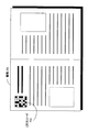
実物体の一例として、識別子(ID)に対応する2次元コード205を表面に印刷した書籍204を用いた例を示す。図3に図2のシステムで用いる書籍のページの例を示す。書籍301は、各ページの一部領域に2次元コード302が印刷されている。2次元コードとしては、サイバーコード、QRコードなどカメラによる撮影画像から的確な識別が可能な構成を用いることが好ましい。
【0057】
なお、サイバーコードとは、本出願人に既に譲渡されている特開2000−82108号公報(「2次元コード認識処理方法、2次元コード認識処理装置、および媒体」)に開示された2次元コードの一形式である。また、QRコードは、ISO/IEC18004として標準化されている2次元コードの一形式である。
【0058】
なお、上記のサイバーコード、QRコード以外の2次元コードを適用してもよく、また、識別子(ID)を示すコードとして、2次元コード以外の例えばバーコード等の1次元コードを適用してもよい。
【0059】
情報処理装置を使用するユーザは、図2に示すように、書籍を情報処理装置に備えられたセンサとしてのカメラ202の撮像可能領域206内に置く。この処理により、例えば書籍204のページに印刷された2次元コード205のIDがカメラ202によって取得されて、データ処理部203においてID識別が実行され、識別されたIDに対応するアプリケーションプログラムの起動処理が行なわれて、データ処理部203で実行されたアプリケーションプログラムの実行結果が、出力部としてのディスプレイ201に表示される。
【0060】
さらに、ユーザが書籍をカメラ202の撮像可能範囲206から外に出すと、書籍204のページに印刷された2次元コード205のIDがカメラ202によって取得されず、ID情報の入力がないことをデータ処理部203において判別し、過去の識別IDに対応して実行中のアプリケーションプログラムの終了処理が行なわれる。このようにしてデータ処理部203で実行されているアプリケーションプログラムは自動的に終了する。これらの処理の詳細については、後段で説明する。
【0061】
本実施例では、図1のセンサ101としてはカメラを用い、実物体識別部102では画像処理による2次元コード認識処理を実行するものとする。実物体識別部102では2次元コードに対応したIDが識別される。情報処理部103では、識別IDの入力状況に基づくアプリケーションプログラムの選択と実行及び終了の処理を行う。
【0062】
アプリケーションプログラムの選択と実行のために、情報処理部103では、実物体識別部102から入力したIDに基づいてID・内部状態対応記憶部104の検索処理を実行し、実行すべきプログラム情報を取得する。ID・内部状態対応記憶部104は、IDとそのIDに対応するプログラムのパスを記憶した処理情報テーブルを格納している。
【0063】
ID・内部状態対応記憶部104に格納された処理情報テーブルの構成例を図4に示す。図4に示すように、処理情報テーブルには、センサによって実物体から読み取られる識別子(ID)と、そのIDに対応して実行すべきプログラムのパスが記録されている。例えば、ID=001012が実物体から読み取られて、実物体識別部102から情報処理部103に入力されると、情報処理部103はIDに基づく実行プログラムの問い合わせ処理として、ID=001012に基づくID・内部状態対応記憶部104のテーブル検索処理を実行する。
【0064】
ID・内部状態対応記憶部104において、ID=001012に基づくテーブル検索が実行され、情報処理部103は、検索結果としての実行ファイルパス:/usr/local/bin/game.exeを取得する。情報処理部103は、実行ファイルパス:/usr/local/bin/game.exeによって指定される例えばゲーム実行プログラムの起動処理を行なう。
【0065】
また、実物体、この場合は、図2に示す書籍204がセンサ(カメラ202)の撮像可能範囲206から除去されると、センサ(カメラ202)の撮像データから、2次元コード205情報が消え、実物体識別部102から情報処理部103に対するID=001012の入力が途切れることになる。情報処理部103は、ID入力の停止に伴い、ID=001012に対応して実行中の実行ファイルパス:/usr/local/bin/game.exeによって指定されるゲーム実行プログラムの終了処理を行なう。
【0066】
本実施例における情報処理部103の詳細構成を図5に示す。実行プログラム選択部402では、実物体識別部102(図1参照)からID入力部401を介して取得したIDを、ID・内部状態対応記憶部I/O403を介してID・内部状態対応記憶部104に出力し、実行すべきアプリケーションプログラムを問合せる。さらに、実行プログラム選択部402では、問い合わせに対する応答としてID・内部状態対応記憶部104からIDに対応する実行ファイルパスを入力し、パスによって特定されるプログラムをプログラム実行部404で実行させる。
【0067】
プログラム実行部404は、ID・内部状態対応記憶部104からIDに基づいて取得したプログラム実行ファイルパスによって特定される実行ファイルをプログラム格納部405からロードし、プログラム処理を実行する。プログラム実行部404におけるプログラムの処理結果はフレームバッファ406に書き込まれ、例えば出力部106のディスプレイ(201)を通じてユーザに提示される。
【0068】
本実施例における情報処理装置の情報処理部における処理、すなわち、実物体からの識別IDに基づくプログラム実行・終了の手順を図6のフローチャートを用いて説明する。
【0069】
まず、ステップS101において、現在実行中のプログラムのパスを示す文字列[CPRG]と次に実行すべきプログラムを表す文字列[NPRG]を空文字列(例えばnull)として初期化する。なお、空文字列(null)の設定処理は、無効な特別なパスの設定として実行し、それをnull(空)とみなすようにしてもよい。
【0070】
次に、ステップS102において、実物体の認識処理を行う。これは、図2の構成例におけるカメラ202が撮影した撮像可能範囲206の画像を、データ処理部203に構成された実物体識別部102に入力して実行する処理である。ステップS102では実物体の有無のみが判定される。なお、このとき、複数の実物体が認識された場合には、適当な基準により1つの実物体を選択する。この選択処理としては、例えば、認識アルゴリズムの出力する「確からしさ」(マッチングを行った時の残差や、統計的推定を用いた場合の尤度等)を用いてもよいし、認識された実物体の位置、例えばよりディスプレイに近いものを選択する等の選択基準の適用が可能である。これらの選択処理により1つの実物体を選択する。
【0071】
さらに、ステップS103において、認識された実物体からIDを識別する処理を実行する。これはステップS102と同様、図2の構成例におけるカメラ202が撮影した撮像可能範囲206の画像を、データ処理部203に構成された実物体識別部102に入力し、入力画像の画像解析によって実行する処理である。例えば2次元コードを取得画像から抽出し、2次元コードに基づいて識別データとしてのIDを取得する。なお、実物体が認識されていなければ、認識されていないことを示す特別なIDを設定、例えばオール0の設定とした特殊IDを実物体識別部において設定し、情報処理部に出力する処理としてもよい。
【0072】
ステップS104では、IDの取得がなされたか否かを判定し、ID取得がなされていない場合、例えばオール0の特殊IDが実物体識別部から情報処理部に出力された場合は、ステップS106において、次期実行プログラム(NPRG:Next Program)設定情報として、NPRG=nullを設定する。NPRG=nullは、次期実行プログラムの設定がないことを示している。
【0073】
ステップS104でのIDの取得判定により、ID取得がなされていると判定された場合は、ステップS105において、IDに基づいて決定される次期実行プログラムをNPRGとして設定する。すなわち、図1に示す情報処理部103が、実物体識別部102から入力するID情報に基づくID・内部状態対応記憶部104のテーブル検索を実行し、検索結果としてプログラムのパス情報を取得し、取得したパス名を表す文字列をNPRGに設定する。この結果、NPRG=次期実行プログラムパスの設定がなされる。
【0074】
ステップS107では、現実行プログラム[CPRG]と次実行プログラム[NPRG]が同一であるかを判定する。同一である場合には、S102へ戻り、実物体の認識、IDの識別処理を繰り返し実行する。すなわち、現実行プログラムを継続したままID識別処理を繰り返し実行する。
【0075】
ステップS107において、現実行プログラム[CPRG]と次実行プログラム[NPRG]が異なると判定された場合には、ステップS108へ進む。ステップS108では、現実行プログラム[CPRG]が存在するか否かの判定を行なう。すなわち、(CPRG=パス設定(CPRG≠null))か、否か(CPRG=null)を判定する。現実行プログラム[CPRG]が存在する(CPRG=パス設定(CPRG≠null))場合には、ステップS109において、現実行プログラム[CPRG]の終了処理を行なう。
【0076】
これは、現実行プログラム[CPRG]と次実行プログラム[NPRG]が異なると判定されたため、現実行プログラム[CPRG]を終了させて、次実行プログラム[NPRG]を開始させるための処理である。これは、新たなIDを持つ実物体が検出されたか、あるいは、検出されていたIDを持つ実物体が検出されなくなった、すなわちセンサ有効領域の外に出されたことを意味する。
【0077】
ステップS108の判定が、現実行プログラム[CPRG]が無い(CPRG=null)の判定の場合には、現在プログラムを実行していないので、そのままステップS110へ進む。
【0078】
ステップS110では、次実行プログラム[NPRG]が設定済み(NPRG=パス設定(NPRG≠null))か、否か(NPRG=null)を判定する。次実行プログラム[NPRG]が設定済み(NPRG=パス設定(NPRG≠null))である場合には、ステップS111において次実行プログラム[NPRG]に設定されたパスに従ってNPRG設定ファイルを取得してプログラムを起動する。これは、新たに検出された実物体のIDに対応するプログラムである。
【0079】
ステップS118の判定が、次実行プログラム[NPRG]が無い(NPRG=null)の判定の場合には、次実行プログラムが設定されていないので、そのままステップS112へ進む。ステップS112では、現実行プログラム[CPRG]の設定値に、次実行プログラム[NPRG]の設定値を代入し、ステップS102へ戻る。
【0080】
上記の手順により、図2に示すシステム構成において、センサ有効領域(カメラの撮像範囲)に実物体(例えば書籍)を置くことにより、実物体に対応して設定されたIDに対応するプログラムが起動する。また、実物体(例えば書籍)をセンサ有効領域(カメラの撮像範囲)外に置くことにより、入力されていたIDと同一のIDの入力が途絶えることになり、図6に示すフローにおけるステップS106において、NPRG=nullの設定がなされ、ステップS107においてCPRG=NPRGが否定(No)されて、ステップS108で現在実行中のプログラムがありと判定され、ステップS109で、現実行プログラム[CPRG]の終了処理が実行される。
【0081】
このように、ユーザはIDの対応付けられた実物体をセンサ有効領域(カメラの撮像範囲)に入れる、あるいは領域から出すという容易な操作を実行するのみで、情報処理装置におけるプログラムを起動または終了させることが可能となる。
【0082】
なお、上述した実施例では、現在実行中のプログラム[CPRG]、あるいは次実行プログラム[NPRG]を表すデータとして、実行プログラムのパスを示す文字列を設定する構成例、すなわち、CPRG=パス名、NPRG=パス名とした設定例を説明したが、このようなパス名を直接設定することなく、センサによって取得したIDを、プログラム状態値、すなわち、CPRG=識別ID、NPRG=識別IDとして持ち、実行プログラムのパスは、IDに基づくハッシュ等の演算、あるいはテーブル検索により逐次検索する構成としてもよい。
【0083】
次に、実行中のプログラムが異常終了した場合の処理について説明する。図6を参照して説明した処理手順では、プログラムが異常終了すると、現実行プログラム[CPRG]の設定値(例えばパス名)が更新されないため、プログラムが終了したままの状態になってしまう。
【0084】
このような状態を回避するため、図5に示す情報処理部103中の実行プログラム選択部402が起動したプログラムを監視する構成とし、プログラムの異常終了を検出した場合に、現実行プログラム[CPRG]の設定値を更新、すなわち、CPRG=nullに更新する処理を実行する。この設定を実行することにより、新たにセンサがIDを識別すれば、図6に示すステップS107で、CPRG=NPRG?の判定がNoとなり、ステップS108の判定がNoとなりステップS110に進み、ステップS110の判定がYesとなり、ステップS111においてID取得により検索されたパス名に基づく次実行プログラム[NPRG]が起動し、以上終了したプログラムの再起動が達成されることになる。
【0085】
実行プログラム選択部402において、プログラムの異常終了を検出する方法は、情報処理装置の持つデータ処理環境(オペレーティング・システム)によって異なるが、例えば、UNIXでは、fork()したプロセスをwait()して待つことで知ることができる。また、Windowsではプロセスの終了をイベントとして通知を受けることができる。このような各種実行OSのプログラム監視処理結果を実行プログラム選択部402(図5参照)が入力し、入力に基づいて、現実行プログラム[CPRG]の設定値の更新処理を実行する。
【0086】
[(2)ネットワーク接続および切断処理]
次に、本発明の情報処理装置および情報処理方法を適用した第2の処理具体例として、通信処理装置においてネットワーク接続および切断処理を実行する例について説明する。
【0087】
図7に、本実施例を実行するための情報処理装置のシステム構成例を示す。このシステムでは、ディスプレイ601上に設置されたカメラ602がセンサとして機能し、カメラ602により、ディスプレイの前の領域を撮像する。カメラ602の撮影可能なディスプレイの前の領域がセンサ有効領域に対応する撮像可能範囲605として設定される。
【0088】
データ処理部603は、図1に示すセンサ101(カメラ602に対応)、出力部106(ディスプレイ601に対応)以外の要素、すなわち、図1の情報処理装置構成の実物体識別部102、情報処理部103、ID・内部状態対応記憶部104、およびネットワーク・インターフェイス105を備えた構成である。
【0089】
本実施例では、実物体としてカード604を用いた例を説明する。なお、カードは実物体の一例であり、その他のあらゆる物体を適用可能である。カード604の認識には、ディスプレイ601の上に設置されたカメラ602の撮影画像を用いる。また、ディスプレイ601、カメラ602、データ処理部603によって構成されるクライアントA607は、データ処理部603内に構成されたネットワーク・インターフェイスを介してネットワーク606に接続されており、このネットワークを通じて、他のクライアントB608と接続可能な状態にある。
【0090】
実物体としてのカードの具体例を図8に示す。本実施例においては、カードをディスプレイの前に置くことにより、目的の相手(各接続先)に、目的の手段(各通信プロトコル)でネットワーク接続を行うことができる。カードにはそれぞれ識別子(ID)を示す2次元コード711,721,731が表面に印刷されている。なお、図8には、カード識別子として2次元コードを用いた例を示したが、識別子(ID)データは、2次元コードのみならず、RFタグに対応するデータとしてもよいし、バーコードとしてもよい。あるいはコード情報ではなく、図に示すような、電話の絵、あるいはメールの絵等、画像情報そのものを識別情報として用いてもよい。
【0091】
本実施例で使用されるカードは、音声通話カード701やメールカード702のように、接続方法を設定するためのプロトコルカード704と、接続相手を設定するための接続先カード703の2つの種類のカードである。
【0092】
例えば接続先Aさんに対して音声通信を実行する場合には、プロトコルカードとして音声通話カード、接続先カードとしてAさんの接続先カードを用いる。また、接続先Bさんに対してメール通信を実行する場合には、プロトコルカードとしてメールカード、接続先カードとしてBさんの接続先カードを用いる。
【0093】
例えば音声通話を実行しようとするユーザは、図7に示すディスプレイ601の前の撮像可能範囲605の領域内に、音声通話カードと話したい相手の顔写真が描かれた接続先カードを置く。すると、カメラ602によって、2つのカードの画像が撮影され、図1における実物体識別部102において、撮影されたカードの識別情報(ID)を取得し、識別情報(ID)が情報処理部103に出力され、情報処理部103において、識別情報に従った処理を実行する。この場合、2つのカテゴリカードの識別情報に基づいて、通信プロトコルの設定および、設定プロトコル上での接続先、すなわちアドレス、電話番号等の処理パラメータの設定処理が実行されることになる。
【0094】
プロトコルおよび通信先設定のために、情報処理部103では、実物体識別部102から入力したIDに基づいて、ID・内部状態対応記憶部104のテーブル検索を実行して、実行すべきプログラム情報を取得する。ID・内部状態対応記憶部104は、IDとそのIDに対応するプログラムのパスを記憶した処理情報テーブルを格納している。
【0095】
ID・内部状態対応記憶部104に格納された処理情報テーブルの構成例を図9に示す。図9に示すように、処理情報テーブルには、(a)に示すプロトコル設定のための処理情報テーブルと、(b)に示す通信先設定のための処理情報テーブルの2種類が存在する。
【0096】
図9(a)のプロトコル設定のための処理情報テーブルには、センサによって実物体から読み取られる識別子(ID)と、そのIDに対応して実行すべき接続プロトコル情報、例えば、メール(mail)、電話(Phone)等が設定されている。図9(b)の通信先設定のための処理情報テーブルには、センサによって実物体から読み取られる識別子(ID)と、そのIDに対応して設定すべき通信先情報としてのホストネームと、ユーザーネームが設定されている。ホスト名、ユーザ名が共に与えられた場合には、指定されたホストの指定されたユーザに対して接続を行う。また、ユーザ名のみ与えられた場合には、そのユーザがどのホストに存在するかを保存したデータベースを保持するサーバへ問合せを行ったのち、データベースから得られたホストへ接続を行う。
【0097】
なお、図9には、(a)のプロトコル設定のための処理情報テーブルと、(b)の通信先設定のための処理情報テーブルとを区別して示しているが、カードに設定されるIDが、プロトコル設定用のカードと、通信先設定用のIDとで重複がないように構成されれば、これらの処理情報テーブルは、ID・内部状態対応記憶部104に格納される場合、区別して格納される必要はない。図9に示す例では、(a)のプロトコル設定用のカードに対応するIDには、上位2桁が[10]のIDが設定され、(b)の通信先設定用のカードに対応するIDには、上位2桁が[01]のIDが設定される構成である。上位2桁が[10]の場合は、プロトコル[PRT]を表わし、上位2桁が[01]の場合は、接続先[CON]を示す。従って、IDの上位データに基づいてカード種類の判別が可能である。なお、ID情報の構成の詳細については後述する。
【0098】
例えば、ID=1001027と、ID=0100021の2つのIDが実物体から読み取られて、実物体識別部102から情報処理部103に入力されると、情報処理部103はIDに基づく処理問い合わせとして、ID=1001027と、ID=0100021をID・内部状態対応記憶部104に出力する。ID・内部状態対応記憶部104において、まずID=1001027に基づくテーブル検索を実行し、検索結果として接続プロトコル情報=メ−ル(mail)を情報処理部103に出力する。さらに、ID・内部状態対応記憶部104において、ID=0100021に基づくテーブル検索を実行し、検索結果として接続先情報=hostA/Aliceを情報処理部103に出力する。
【0099】
情報処理部103は、接続プロトコルとして、メールを設定し、接続先としてhostA/Aliceを設定してアリス(Alice)に対するメールによる通信設定処理を行なう。
【0100】
実行中の通信を切断したいときには、先の実施例1と同様、単純にディスプレイ前の撮像可能範囲からカードを除去すればよい。実物体、この場合は、図7に示すカード604がセンサ(カメラ602)の撮像可能範囲605から除去されると、センサ(カメラ602)の撮像データから、カードが消え、図1に示す実物体識別部102から情報処理部103に対するIDの入力が途切れることになる。情報処理部103は、ID入力の停止に伴い、IDに対応して実行中の通信処理の終了処理を行なう。
【0101】
また、音声通話に相手が応答しないために、メールでメッセージを送ろうとする場合には、音声通話カードをメールカードに置き換えればよい。本実施例では、図1のセンサ101として、カメラを用いる。よって、図1に示すセンサ有効領域110はカメラの撮像可能範囲となる。また、実物体111として、種類によって異なる絵が描かれたカードを用いる。このとき、実物体識別部103は、カード上のコードあるいは画像認識等によりカードの絵柄を識別して各カードに対応するIDを取得する。
【0102】
情報処理部103では、識別されたカードのIDに基づいて、ID・内部状態対応記憶部104に処理問い合わせを実行し、問い合わせ結果に基づいてプロトコルの設定および宛先設定処理を実行し、ネットワーク・インターフェイス105を介してネットワーク接続を行う。また、その処理の結果を出力部106としての図7に示すディスプレイ601、およびスピーカ(図示しない)によりユーザに対して出力する処理を実行する。
【0103】
本実施例における情報処理装置の情報処理部における処理、すなわち、実物体からの識別IDに基づく通信プロトコルの設定および宛先設定に基づく通信処理の手順を図10、図11、図12のフローチャートを用いて説明する。
【0104】
なお、ここで説明する手順において使用する変数は、以下に示す通りである。
ID_QUEUE:カードに基づいて検出されたIDを格納するためのキュー
ID_TYPE:ID情報のうちカードのタイプすなわち種類(プロトコルカードであるか接続先カードであるか)を示すタイプ情報
ID_DATA:ID情報のうちプロトコルの具体的情報または接続先の具体的情報を示すデータ情報
PDATA:現設定プロトコルを示す情報
CDATA:現設定接続先を示す情報
CFLG:接続情報が変更されたか否かを示すフラグ情報
【0105】
前述したように、本実施例では、2種類のカード、すなわち、プロトコルカードおよび接続先カードを適用し、通信プロトコルの設定を行なうとともに、接続先の設定を実行する。図1における情報処理部103では、この2つの情報を適用した処理を実行することになる。情報処理部103では、実物体識別部102から入力したIDを、情報処理部103内のキュー[ID_QUEUE]に格納する。具体的なプロトコルや接続先情報は、IDに基づいて、ID・内部状態対応記憶部104から取得可能である。
【0106】
情報処理部103では、実物体識別部102から入力したIDに基づいて、接続プロトコル、接続先の具体的情報をID・内部状態対応記憶部104から取得し、取得情報に基づいてID情報を設定しメモリに格納する。図13に、情報処理部103内のメモリに格納するID情報のデータ形式を示す。ID情報は、カードのタイプすなわち種類(プロトコルカードであるか接続先カードであるか)を示すタイプ情報[ID_TYPE]と、ID情報のうちプロトコルの具体的情報または接続先の具体的情報を示すデータ情報[ID_DATA]とによって構成される。
【0107】
ID情報の上位n[bit]がID_TYPEとして、下位m[bit]がID_DATAとして用いられる。ID_TYPEの値としては、プロトコル[PRT]を示す値、あるいは接続先[CON]を示す値のいずれかが設定される。ID_TYPEが[PRT]の場合のID_DATAとしては、「音声電話」「メール」「ビデオチャット」などの接続手段の種類を示す値が格納される。
【0108】
また、ID_TYPEが[CON]の場合には、ID_DATAとしては、接続先のIPアドレスやホスト名、ニックネーム等が格納される。ニックネームを格納する場合には、ニックネームから実際に接続すべきマシンのIPアドレスを検索することのできるデータベースサーバからアドレスを取得する。
【0109】
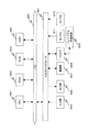
本実施例における通信接続・切断処理の具体的シーケンスを図10〜図12を参照して説明する。図10は、本実施例における通信接続・切断処理の全体シーケンスを示しており、図11は、図10のステップS203の接続情報更新チェック処理の詳細シーケンス、図12は、図10のステップS204のネットワーク状態の更新処理の詳細シーケンスを示している。
【0110】
まず、図10のステップS201において、本手順において使用する変数の初期化処理を行う。初期化処理では、カードに基づく取得ID情報格納キュー[ID_QUEUE]を空にし、現設定プロトコルを示す情報[PDATA]と、現設定接続先を示す情報[CDATA]は空文字列(null)とし、接続情報が変更されたか否かを示すフラグ情報[CFLG]はOFF(false)に設定する。
【0111】
次に、ステップS202において、実物体を識別し、その実物体に対応するIDを全てID_QUEUEに格納する。なお、ID取得処理は、図1に示す実物体識別部102においてセンサ101から入力される例えば画像情報に基づいて実行する。IDはバーコード、2次元コード等のコード情報に基づいて取得するか、あるいは、カメラで撮影された画像を、用意されたテンプレート画像とマッチングさせることにより電話の絵、メールの絵自体に基づいて取得するなど様々な態様が可能である。取得したIDが、図1に示す情報処理部103に出力され、情報処理部103において、データ記憶部としての取得ID情報格納キュー[ID_QUEUE]に格納される。
【0112】
なお、ここで、同じID_TYPEを持つ複数カード、すなわち複数のプロトコルカード、あるいは複数の接続先カードが認識された場合には、それぞれのID_TYPEについて、現在のID_DATAと同じ値のカードを優先し、取得ID情報格納キュー[ID_QUEUE]に格納する。すなわち、取得ID情報格納キュー[ID_QUEUE]には、プロトコルカードのIDと、接続先カードのIDの1つずつのみが格納可能である。
【0113】
なお、プロトコルカードまたは接続先カードがセンサ検出領域内に存在しない場合は、図1における実物体識別部102は、プロトコルカードまたは接続先カードの存在しないことを示す情報を取得ID情報として情報処理部103に出力する。例えば、図9に示すID設定、すなわちプロトコルカードを示すID情報の上位データが[10]で、接続先カードを示すID情報の上位データが[01]とした設定の場合、プロトコルカードが存在しない場合は、実物体識別部102は、ID情報の下位データをオール0とした特殊ID:[1000000]を情報処理部103に出力し、また、接続先カードが存在しない場合は、実物体識別部102は、ID情報の下位データをオール0とした特殊ID:[0100000]を情報処理部103に出力する。情報処理部103は、これらのIDをキュー[ID_QUEUE]に格納する。
【0114】
次に、ステップS203において、接続情報の更新のチェックを行う。これは、ステップS202において識別されたIDと、現在のネットワーク接続の情報を比較し、ネットワーク接続状態を変更するかを調べる処理である。次に、ステップS204において、ステップS203で調べた結果に基づき、必要であればネットワークの接続状態を変更する。最後に、ステップS205において、終了判定を行い、引き続きID識別に基づく処理を実行する場合には、ステップS202へ戻る。
【0115】
ステップS203の「接続情報の更新チェック」の詳細について、図11を用いて説明する。まず、ステップ301において、取得ID情報格納キュー[ID_QUEUE]が空であるかをチェックする。空であれば、サブルーチンを終了する。
【0116】
取得ID情報格納キュー[ID_QUEUE]内に格納IDが存在すればステップS302へ進む。ステップS302においては、取得ID情報格納キュー[ID_QUEUE]の先頭からIDを1つ取り出し、そのIDに基づいて具体的なプロトコルまたは接続先情報をID・内部状態対応記憶部104から取得し、取得情報に基づくタイプ、データを、[ID_TYPE]と[ID_DATA]として設定する。なお、キュー[ID_QUEUE]からのID取得処理により、キューは、ID格納領域が1つ空き、新たなIDを格納することが可能となる。
【0117】
このとき、センサ(カメラ)による読み取り画像中にカードが存在し、キューから読み取られたIDと同一種類(プロトコルまたは接続先)のカードIDが読み取られた場合は、取得ID情報格納キュー[ID_QUEUE]内に格納されることになる。例えば同一プロトコルカードがセンサの読み取り領域内に継続して存在すれば、取得ID情報格納キュー[ID_QUEUE]からのID取得後、即座に同一プロトコルのID情報が格納される。
【0118】
また、同一接続先カードがセンサの読み取り領域内に継続して存在すれば、取得ID情報格納キュー[ID_QUEUE]からの接続先ID取得後、即座に同一接続先のID情報が格納される。
【0119】
次に、ステップS303において、[ID_TYPE]がPRT(プロトコル情報)であるかを判定する。[ID_TYPE]がプロトコル情報であれば、ステップS304へ、そうでなければ、ステップS306へ進む。
【0120】
ステップS304では、現設定プロトコルを示す情報[PDATA]とID情報から得られたプロトコル情報[ID_DATA]が同一であるかを判定する。すなわち、新規取得IDに基づく現プロトコルの変更処理が必要か否かを判定する。変更が必要、すなわち、PDATA≠ID_DATAであれば、ステップS305へ進む。変更が不要、すなわち、PDATA=ID_DATAであれば、ステップS301へ戻り、取得ID情報格納キュー[ID_QUEUE]からのID取得を繰り返し実行する。
【0121】
ステップS305では、現設定プロトコルを示す情報[PDATA]をID情報から得られたプロトコル情報[ID_DATA]の値に更新し、ステップS309へ進む。ステップS309では、現設定プロトコルを示す情報[PDATA]、または、現設定接続先を示す情報[CDATA]が変更されたこと示すフラグ[CFLG]をON(true)に設定し、ステップS301以下の処理を繰り返し実行する。
【0122】
ステップS303において、[ID_TYPE]がPRT(プロトコル情報)でない場合は、ステップS306へ進み、[ID_TYPE]がCON(接続先情報)であるかを判定する。[ID_TYPE]が接続先情報であればステップS307へ進み、そうでなければステップS301へ戻る。
【0123】
ステップS307では、現設定接続先を示す情報[CDATA]とID情報から得られた接続先情報[ID_DATA]が同一であるか否かを判定する。すなわち、新規取得IDに基づく現接続先の変更が必要か否かを判定する。変更が必要、すなわち、CDATA≠ID_DATAであれば、ステップS308へ進み、変更が不要、すなわち、CDATA=ID_DATAであれば、ステップS301へ戻り、取得ID情報格納キュー[ID_QUEUE]からのID取得を繰り返し実行する。
【0124】
ステップS308では、現設定接続先を示す情報[CDATA]をID情報から得られた接続先情報ID_DATAの値に設定し、ステップS309へ進む。ステップS309では、PDATA又はCDATAが変更されたこと示すフラグ[CFLG]をON(true)に設定し、ステップS301へ戻る。
【0125】
続いて、図10の処理フローにおけるステップS204の「ネットワーク状態の更新」の詳細処理について、図12を用いて具体的に説明する。
【0126】
ステップS501において、ネットワーク状態を更新すべきかを示すフラグ[CFLG]がONに設定されているかを調べ、ネットワーク状態を更新すべきことを示す値[ON]が設定されていれば、ステップS502へ進み、ネットワーク状態の更新不要を示す値であれば終了する。
【0127】
[CFLG]にネットワーク状態を更新すべきことを示す値[ON]が設定されている場合、ステップS502に進み、本手順によって確立されたネットワークの現在の状態を調べる。通信処理が継続中、すなわち接続中であればステップS503へ進み、現在、接続中のネットワークを切断し、接続中でなければステップS504へ進む。
【0128】
次に、ステップS504において、現設定プロトコルを示す情報[PDATA]と現設定接続先を示す情報[CDATA]の設定値が有効な値であるかを調べる。もし、有効な値であれば、ステップS505へ進み、現設定プロトコルを示す情報[PDATA]と現設定接続先を示す情報[CDATA]に基づいて、ネットワーク接続を確立し、無効な値、例えば「null」が設定されていれば終了する。
【0129】
先に説明したように、同一プロトコルカードがセンサの読み取り領域内に継続して存在すれば、取得ID情報格納キュー[ID_QUEUE]からのID取得後、即座に同一プロトコルのID情報が格納され、同一接続先カードがセンサの読み取り領域内に継続して存在すれば、取得ID情報格納キュー[ID_QUEUE]からの接続先ID取得後、即座に同一接続先のID情報が格納されることになり、現設定プロトコルを示す情報[PDATA]と現設定接続先を示す情報[CDATA]のそれぞれには、それぞれのカードから取得されたIDが継続して設定されるので、通信が継続して実行される。
【0130】
また、通信中のプロトコルカードがセンサの読み取り領域外に排除され、異なるプロトコルカードがセンサの読み取り領域内に置かれた場合には、新たなプロトコルカードのIDが、取得ID情報格納キュー[ID_QUEUE]に新たに格納されて、現設定プロトコルを示す情報[PDATA]が新たなプロトコルカードに対応するIDに更新されて、新たなプロトコルで、同一の接続先との通信が実行されることになる。
【0131】
また、通信中の接続先カードがセンサの読み取り領域外に排除され、異なる接続先カードがセンサの読み取り領域内に置かれた場合には、新たな接続先カードのIDが、取得ID情報格納キュー[ID_QUEUE]に新たに格納されて、現在の接続先を示す情報[CDATA]が新たな接続先カードに対応するIDに更新されて、新たな接続先に対して、同一のプロトコルを適用して通信が実行されることになる。
【0132】
さらに、通信中のプロトコルカード、あるいは通信中の接続先カードがセンサの読み取り領域外に排除され、異なるプロトコルカード、接続先カードがセンサの読み取り領域内に置かれなかった場合には、取得ID情報格納キュー[ID_QUEUE]には、有効なプロトコル情報、あるいは有効な接続先情報を持たないID情報、例えば、前述したようにデータ部をオール0とした特殊IDが格納される。
【0133】
この場合、図11に示すステップS305またはステップS308の現設定プロトコルを示す情報[PDATA]、あるいは現設定接続先情報[CDATA]に無効な値が設定され、ステップS309で、ネットワーク状態を更新すべきかを示すフラグ[CFLG]がONに設定される。従って、図12のステップS501の判定がYesとなり、現在接続中の通信があれば、ステップS503で切断処理がなされて、ステップS504で、新たな現設定プロトコルを示す情報[PDATA]、あるいは現設定接続先情報[CDATA]が無効と判断され、新たな接続が実行されることなく、処理が終了する。
【0134】
以上の手順により、プロトコルと接続先を示すカードの組を特定領域に置いている間だけ、ネットワークの接続が確立するというシステムを実現することができる。
【0135】
なお、あるプロトコルを用いてネットワーク接続を実行する場合、それぞれのプロトコルごとに対応する異なるアプリケーションプログラムを起動してもよいし、1つのアプリケーションプログラム内で、接続プロトコルを切り替えてもよい。また、以上の実施例では、カードとカメラを用いて実物体の認識を行なう例を説明したが、RFIDタグを埋め込んだ模型(電話の模型など)と、RFIDリーダを適用してID検出を実行する構成としても同様の処理が実施可能である。その他のID検出態様を適用してもよい。
【0136】
[(3)実物体の存在の有無判別に基づくロバスト性を向上した処理]
次に、本発明の情報処理装置および情報処理方法を適用した第3の処理具体例として、実物体の存在の有無判別に基づくロバスト性を向上した処理を実行する例について説明する。
【0137】
本実施例は、認識対象の実物体が領域内に存在するかを識別する手段と、実物体の種類を識別する手段とを併用することにより、システムのロバスト性を高めた構成である。
【0138】
前述した実施例の説明から理解されるように、本発明の情報処理装置は、ある実物体がセンサ有効領域に対応する特定領域にあるか否かを判定し、処理の開始、終了、あるいはパラメータ設定等の処理を実行し、情報処理装置の内部状態を変化させる構成とした場合、実物体のIDの上部にユーザの手が覆われるなど、ID読み取りにセンサが失敗する場合が発生し得る、このような時に、例えばアプリケーションの終了、あるいは通信処理の終了を実行するとユーザの意図しない処理が実行されてしまうことになる。
【0139】
これを、実施例1で説明した、書籍上の2次元コードを利用したアプリケーションプログラムの起動・終了方法を使って説明する。カメラを用いて2次元コードの認識を実行する場合、2次元コードがカメラの撮影するフレームの一部において認識できない場合が生じる。これは、画像のノイズによる認識アルゴリズムの破綻や、ユーザの手が2次元コードの一部又は全てを隠してしまった場合などに生じる。
【0140】
このような場合、センサ有効領域からのIDの消滅と判定し、アプリケーションを終了させてしまい、次のフレームでは、IDが認識され、アプリケーションを起動させることになる。このように処理を忠実に実行すると、頻繁にアプリケーションプログラムの終了・起動が生じるようになり不都合が発生する。
【0141】
本実施例は、この問題を解決するために、図1の情報処理装置100に構成される実物体識別部102に、認識対象の実物体が領域内に存在するかを判定する実物体存在判定部と、実物体の種類を識別する実物体種類判定部の2つの判定部を設けた。これらの2つの異なる判定に基づく処理を実行し、情報処理装置における処理の頻繁な起動、終了等の発生を抑え、ロバスト性の高い安定な処理を可能とした。すなわち、IDの識別が一時的に不可能となった場合であっても、実物体の存在が確認されれば、情報処理装置における状態更新を行なわず、再度ID識別処理に移行する構成として安定した制御を可能とした。
【0142】
本実施例の実物体識別部102の詳細構成を図14に示す。図14に示すように、本実施例の実物体識別部102は、認識対象の実物体がセンサ有効領域内に存在するかを判定する実物体存在判定部802と、実物体のIDを識別する実物体ID判定部803の2つの判定部を設ける。実物体存在判定部802と、実物体のIDを識別する実物体ID判定部803の2つの判定部は、それぞれセンサ・データ入力部801からセンサ入力情報、例えばカメラの撮影画像を入力し、各判定部における判定結果を認識結果出力部804を介して情報処理部103(図1参照)に出力する。
【0143】
以下では、具体的に、上述の実施例1で説明した書籍を用いてアプリケーションプログラムを起動・終了するシステムに基づいて説明する。しかし、本実施例で説明する方法は、実施例1の形態のみでなく、実施例2で説明した通信処理他、様々な実物体を用いてIDを取得し、IDに基づいて内部状態を変更する情報処理装置一般に適用することができる。
【0144】
図15に、本実施例を実行するための情報処理装置のシステム構成例を示す。このシステムでは、ディスプレイ901上に設置されたカメラ902がセンサとして機能し、カメラ902により、ディスプレイの前の領域を撮像する。カメラ902の撮影可能なディスプレイの前の所定領域がセンサ有効領域に対応する撮像可能範囲900として設定されることは実施例1と同様である。データ処理部903は、図1に示すセンサ101(カメラ602に対応)、出力部106(ディスプレイ901に対応)以外の要素、すなわち、図1の情報処理装置構成の実物体識別部102、情報処理部103、ID・内部状態対応記憶部104、および必要に応じてネットワーク・インターフェイス105を備えた構成である。なお、実物体識別部102は、図14に示すように、2つの判定部を持つ構成である。
【0145】
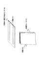
さらに、本実施例においては、実物体としての書籍904がセンサ有効領域内に存在するか否かを検出するための実物体(書籍)検出センサ905を有する。実物体(書籍)検出センサ905は、センサ有効領域としての撮像可能範囲900内に配置される。
【0146】
この実物体(書籍)検出センサ905は、センサ有効領域内に実物体としての書籍が存在するかのみを検出することが目的であり、書籍のIDを識別する処理は実行しない。よって、実物体(書籍)検出センサ905自体は、簡単な仕組みで実現することができる。
【0147】
図16に実物体(書籍)検出センサ905の実現例を1つ示す。書籍を置く板状のセンサにフォトディテクタ906が複数埋め込まれている。実物体(書籍)検出センサ905上に実物体としての書籍が領域内に存在する時には光が遮られる。これを利用して実物体としての書籍の存在を簡単に検出することができる。
【0148】
具体的には、まず、各フォトディテクタの出力を適当な閾値で2値化し、「明」「暗」のどちらの状態かを判定する。「暗」と判定されたフォトディテクタの数がある閾値以上であれば、書籍が存在すると判定する。
【0149】
具体的には、図17に示すように実物体(書籍)検出センサ905上に書籍が置かれている場合は、実物体(書籍)検出センサ905上の多数のフォトディテクタへの光が遮られ、実物体(書籍)検出センサ905上のフォトディテクタからの出力の2値化処理を実行する2値化処理部907において、明なら[0]、暗なら[1]等の2値化処理を実行し、さらに、各2値化データの総加算値を演算部908において算出して、演算部908の出力を実物体検出判定部909において、出力値を所定の閾値と比較して実物体の有無を判定する。図17の例では、6つのフォトディテクタ中、5個のフォトディテクタの出力が暗であり[1]、1つのみが明で[0]であり、演算部908からの出力値は[5]となる。ここで、実物体検出判定部909において閾値を[4]として設定し、出力値>4のとき、実物体が有ると判定するとすれば、演算部908からの出力値は[5]であるので、実物体(書籍)が存在すると判定される。
【0150】
一方、図18に示すように実物体(書籍)検出センサ905上に実物体(書籍)が置かれていない場合は、実物体(書籍)検出センサ905上のほとんどのフォトディテクタへの光が遮られることがない。この場合は、実物体(書籍)検出センサ905上のフォトディテクタからの出力の2値化処理を実行する2値化処理部907において、6つのフォトディテクタ中、1個のみのフォトディテクタの出力がユーザの手によって遮られて暗であり[1]、他の5つが明で[0]であり、演算部908からの出力値は[1]となる。ここで、実物体検出判定部909において閾値を[4]として設定し、出力値>4のとき、実物体が有ると判定するとすれば、演算部908からの出力値は[1]であるので、実物体(書籍)が存在しないと判定される。
【0151】
図19には、本実施例で適用可能な実物体検出センサとしてのもう1つの書籍検出センサの実現例を示す。この形態では、書籍904の背の部分に、導電性シート912を貼る。一方、書籍検出センサ905には、2つの電極911を設け、この2つの電極911間が導通しているか否かを計測する。
【0152】
2つの電極911間が導通している場合には、書籍検出センサ905上に書籍904が存在すると判定し、導通していない場合には存在しないと判定する。この構成によれば、フォトディテクタを用いることなく、簡易な構成で実物体の有無を判定することが可能となる。上述した構成以外にも、光センサや赤外線センサを用いる方法や物理的なスイッチ構成、あるいは、実物体に磁性体を装着して磁気センサによって実物体を検出するなど、様々な手法が適用可能である。
【0153】
なお、図15で示したシステム構成例では、実物体の有無を検出するための専用の実物体(書籍)検出センサ905を適用する構成としたが、このように専用の実物体検出センサを適用することなく、IDを検出するセンサを実物体の検出センサとして併用する構成としてもよい。
【0154】
すなわち、実物体の種類(ID)を識別するセンサ(この場合はカメラ902)を、実物体(例えば書籍)の有無の検出のために用いてもよい。すなわち、カメラ902の撮影画像に基づいてIDを取得するのみならず、実物体(書籍)自身の存在の有無を判定する。
【0155】
具体的には、例えば、カメラ902の取得画像を解析して実物体の有無を判定する。画像の差分を利用した書籍検出方法を説明する。まず、システムの初期化時にカメラからの映像を参照用画像として保存する。この参照用画像には、実物体が何もない状態で撮影した画像を適用する。
【0156】
処理実行時には、図14に示す実物体識別部102の実物体存在判定部802において、カメラからの画像を入力し、参照用画像とカメラからの入力画像との画素比較を行なう。すなわち、参照用画像とカメラからの入力画像との対応画素の差を取り、その差の絶対値を全ての画素に渡って合計し差分合計データを取得する。この差分合計データ値が、あらかじめ定めた閾値より大きかった場合、実物体が対象領域内に存在すると判定する。差分合計データ値が、あらかじめ定めた閾値より小さい場合、実物体が対象領域内に存在しないと判定する。このようにすることにより、実物体の存在の判定と実物体の種類の判定を1つのセンサで実現することができる。
【0157】
なお、実物体の有無を調べる方法をいくつか説明したが、これらの検出方法は必ずしも1つだけを適用する必要はなく、複数の検出方法を併用し、各検出方法による検出結果を総合的に判定し、最終結果としてもよい。例えば、図19に示した導通のチェックによる判定と同時に、画像差分による判定法を用いて、総合的に判定することにより、実物体の有無をより確実に実行し、情報処理装置における処理の不安定性を排除して、ロバスト性を高めることが可能となる。
【0158】
上述した構成により、実物体が存在するか否かの判定結果と、実物体が存在する場合の実物体のID認識結果が別々に得られる。次に、このような2つの識別情報を利用して、情報処理装置の状態遷移をロバストに行う方法を、実施例1で説明したプログラムの起動・終了処理を例にして説明する。
【0159】
本実施例の方法を適用したアプリケーションプログラムの起動・終了の手順は、図20に示す処理となる。
【0160】
この手順において用いる変数は、実施例1で用いた、次実行プログラム[NPRG]、現実行プログラム[CPRG]の他に、実物体が対象領域内に存在したかを示すフラグ[FOUND]を用いる。図20に示す処理フローの各ステップの処理について説明する。
【0161】
まず、ステップS401において、変数の初期化を行う。次実行プログラム[NPRG]、現実行プログラム[CPRG]を空文字列(例えばnull)として初期化する。なお、空文字列(null)の設定処理は、無効な特別なパスの設定として実行し、それをnull(空)とみなすようにしてもよい。実物体が対象領域内に存在したかを示すフラグ[FOUND]は(false)に設定する。
【0162】
次に、ステップS402において、実物体が存在するかを調べる。これは、図15の構成例における実物体検出センサ905による実物体の検出処理として実行される。なお、実物体の検出手段としては、前述したように、フォトディテクタ、導電性シートと電極、カメラの撮影画像等、様々な構成が適用可能である。図14に示す実物体識別部102内の実物体存在判定部802にこれらの検出手段から入力がなされ、入力情報に基づいてセンサ有効領域内に実物体が存在するか否かの判定が実行される。
【0163】
なお、この実物体存在認識処理では、実物体の種類(ID)を判定する必要はない。つまり、実物体が書籍の場合、2次元コードの識別を行う必要はなく、書籍が存在するか否かだけを調べる。
【0164】
ステップS403の実物体存在認識結果の判定に応じて、実物体が存在する場合には、ステップS404へ進み、実物体が対象領域内に存在したかを示すフラグ[FOUND]を、実物体存在を示す(true)に設定し、存在しなかった場合には、ステップS405へ進み[FOUND]を、実物体の非存在を示す(false)に設定する。
【0165】
ステップS406では、実物体のID認識処理を行う。これは、センサによるID検出処理であり、図15の構成例においては、カメラ902が撮影した撮像可能範囲900の画像を、データ処理部903に構成された実物体識別部102の実物体ID判定部803(図14参照)に入力し、入力画像に含まれる例えば2次元コードに基づいてID認識を行なうものである。なお、ID認識処理は、2次元コードに限らず、バーコード、RFタグ、撮影画像自体の解析等によって行なう構成としてもよい。
【0166】
ステップS407において、ID認識が成功したか否かを判定し、ID認識が成功した場合は、ステップS408に進み、IDに対応する次期実行プログラムを[NPRG]として設定する。すなわち、図1に示す情報処理部103が、実物体識別部102から入力するID情報に基づいてID・内部状態対応記憶部104のテーブル検索を実行し、プログラムのパス情報を取得し、取得したパス名を表す文字列をNPRGに設定する。この結果、NPRG=次期実行プログラムパスの設定がなされる。
【0167】
一方、ID取得がなされていない場合、例えばオール0の特殊IDが実物体識別部から情報処理部に出力された場合は、ステップS409において、次期実行プログラム[NPRG]の設定情報として、NPRGを空(例えばnull)に設定する。NPRG=nullは、次期実行プログラムの設定がないことを示している。
【0168】
次に、ステップS410では、現実行プログラム[CPRG]と次実行プログラム[NPRG]が同一であるかを判定する。同一である場合には、S402へ戻り、実物体の認識、IDの識別処理を繰り返し実行する。
【0169】
また、CPRGとNPRGが異なる場合には、ステップS411へ進む。ステップS411では、実物体が対象領域内に存在したかを示すフラグ[FOUND]が(true)かつ次実行プログラム[NPRG]=空文字列(null)であるかを調べる。
【0170】
もしステップS411の判定がYesであれば、実物体はセンサ有効領域に存在するが、何らかの理由で実物体のID識別に失敗したものとみなせるので、ステップS402へ戻り、実物体およびID認識処理を繰り返し実行する。
【0171】
もしステップS411の判定がNoであれば、ステップS412へ進む。ステップS412において、現実行プログラム[CPRG]の値を調べる。現実行プログラム[CPRG]が空文字列でない、すなわち、現在起動しているプログラムが存在する場合には、ステップS413へ進み、その現実行プログラム[CPRG]を終了する。
【0172】
続いて、ステップS414において、次実行プログラム[NPRG]の値を調べる。次実行プログラム[NPRG]が設定済み(NPRG=パス設定(NPRG≠null))か、否(NPRG=null)かを判定する。次実行プログラム[NPRG]が設定済み(NPRG=パス設定(NPRG≠null))である場合には、ステップS415において次実行プログラム[NPRG]に設定されたパスに従ってNPRG設定ファイルを取得してプログラムを起動する。
【0173】
ステップS414の判定が、次実行プログラム[NPRG]がない(NPRG=null)の判定の場合には、次実行プログラムがないので、そのままステップS416へ進む。ステップS416では、現実行プログラム[CPRG]の設定値に、次実行プログラム[NPRG]の設定値を代入し、さらに、次実行プログラム[NPRG]に空文字列(null)を設定し、ステップS402へ戻り、実物体識別およびID識別を繰り返し実行する。
【0174】
上述した処理に従えば、実物体のID取得に失敗しても、実物体の存在が確認されれば、ステップS411の判定がYesとなり、ステップS413の現実行プログラム[CPRG]の終了処理に移行しないので、現実行プログラムが継続して実行され、ID取得ミスによるプログラムの終了が発生せず、プログラムの起動終了を頻繁に繰り返されることがなくなり、安定性の高いロバストな制御が可能となる。
【0175】
[システム構成]
次に、図21を参照して、本発明に係る情報処理装置の具体的なハード構成例について説明する。図21に示すCPU(Central processing Unit)951は、各種アプリケーションプログラムや、OS(Operating System)を実行するプロセッサである。ROM(Read-Only-Memory)952は、CPU951が実行するプログラム、あるいは演算パラメータとしての固定データを格納する。RAM(Random Access Memory)953は、CPU951の処理において実行されるプログラム、およびプログラム処理において適宜変化するパラメータの格納エリア、ワーク領域として使用される。HDD954はハードディスクの制御を実行し、ハードディスクに対する各種データ、プログラムの格納処理および読み出し処理を実行する。
【0176】
バス960はPCI(Peripheral Component Internet/Interface)バス等により構成され、各モジュール、入出力インターフェイス961を介した各入手力装置とのデータ転送を可能にしている。
【0177】
入力部955は、例えば、キーボード、ポインティングデバイス等によって構成され、CPU951に各種のコマンド、データを入力するためにユーザにより操作、あるいは入力される。出力部956は、画像を表示する例えばCRT、液晶ディスプレイ等であり、各種情報をテキストまたはイメージ等により表示する。
【0178】
通信部957は他デバイスとの通信処理を実行する。ドライブ958は、フレキシブルディスク、CD−ROM(Compact Disc Read Only Memory),MO(Magneto optical)ディスク,DVD(Digital Versatile Disc)、磁気ディスク、半導体メモリなどのリムーバブル記録媒体959の記録再生を実行するドライブであり、各リムーバブル記録媒体959からのプログラムまたはデータ再生、リムーバブル記録媒体959に対するプログラムまたはデータ格納を実行する。
【0179】
センサA971は、上述した実施例において説明したように、カメラ、RFリーダ等によって構成され、センサ有効領域内に置かれた実物体からID情報を取得する。センサB972は、実物体の存在を認識するためのセンサであり、上述した実施例において説明したように、フォトディテクタ、導電体を介する電流検出手段、その他の光学センサ、磁気センサ等によって構成され、センサ有効領域内の実物体の有無を検出する。
【0180】
上述した各実施例において、フローチャートを用いて説明した各処理、すなわち、情報処理装置におけるアプリケーションプログラムの起動、終了、通信処理の開始、終了、接続先の変更、パラメータの変更等の各種処理は、ROM他の記憶媒体に記録されたプログラムに従って、センサA971、センサB972の入力情報に基づいて、CPU951において処理を決定し、その結果に基づく処理を実行する。
【0181】
以上、特定の実施例を参照しながら、本発明について詳解してきた。しかしながら、本発明の要旨を逸脱しない範囲で当業者が該実施例の修正や代用を成し得ることは自明である。すなわち、例示という形態で本発明を開示してきたのであり、限定的に解釈されるべきではない。本発明の要旨を判断するためには、冒頭に記載した特許請求の範囲の欄を参酌すべきである。
【0182】
なお、明細書中において説明した一連の処理はハードウェア、またはソフトウェア、あるいは両者の複合構成によって実行することが可能である。ソフトウェアによる処理を実行する場合は、処理シーケンスを記録したプログラムを、専用のハードウェアに組み込まれたコンピュータ内のメモリにインストールして実行させるか、あるいは、各種処理が実行可能な汎用コンピュータにプログラムをインストールして実行させることが可能である。
【0183】
例えば、プログラムは記憶媒体としてのハードディスクやROM(Read Only Memory)に予め記録しておくことができる。あるいは、プログラムはフレキシブルディスク、CD−ROM(Compact Disc Read Only Memory),MO(Magneto optical)ディスク,DVD(Digital Versatile Disc)、磁気ディスク、半導体メモリなどのリムーバブル記録媒体に、一時的あるいは永続的に格納(記録)しておくことができる。このようなリムーバブル記録媒体は、いわゆるパッケージソフトウエアとして提供することができる。
【0184】
なお、プログラムは、上述したようなリムーバブル記録媒体からコンピュータにインストールする他、ダウンロードサイトから、コンピュータに無線転送したり、LAN(Local Area Network)、インターネットといったネットワークを介して、コンピュータに有線で転送し、コンピュータでは、そのようにして転送されてくるプログラムを受信し、内蔵するハードディスク等の記憶媒体にインストールすることができる。
【0185】
なお、明細書に記載された各種の処理は、記載に従って時系列に実行されるのみならず、処理を実行する装置の処理能力あるいは必要に応じて並列的にあるいは個別に実行されてもよい。
【0186】
【発明の効果】
以上、説明したように、本発明の構成によれば、実物体を検出するセンサからの入力情報に基づいて実物体に対応するID(識別子)を取得し、取得IDを継続して繰り返し情報処理部に入力し、情報処理部において、新規入力IDに対応して設定される処理と、既入力IDに対応して設定される処理との比較を実行し、両処理が異なる処理となったことを条件として、実行中の処理の終了処理を行なう構成としたので、センサ有効領域(例えばカメラの撮像範囲)に実物体を置くことにより、実物体に対応して設定されたIDに対応するプログラムの起動が可能となるとともに、実物体をセンサ有効領域外に置くことにより、実物体に対応して設定されたIDに対応するプログラムの処理終了を行なうことが可能となる。ユーザはIDの対応付けられた実物体をセンサ有効領域に入れる、あるいは領域から出すという容易な操作を実行するのみで、情報処理装置におけるプログラムを起動または終了させることができる。
【0187】
さらに、本発明の構成によれば、2種類のID情報を2種類の実物体、例えばプロトコルカードおよび接続先カードに基づいて取得し、通信プロトコルの設定を行なうとともに、接続先の設定を実行することが可能となり、ユーザはIDの対応付けられた実物体をセンサ有効領域(例えばカメラの撮像範囲)に入れる、あるいは領域から出すという容易な操作を実行するのみで、通信の開始、終了が可能となるばかりでなく、通信プロトコルの設定変更、接続先の変更等の制御を実行することも可能となる。
【0188】
さらに、本発明の構成によれば、実物体のIDの取得とともに、実物体の存在の判定に基づいて情報処理装置における制御を実行する構成としたので、実物体のID取得に一時的に失敗した場合であっても、実物体の存在が確認されれば、現実行プログラムの終了処理に移行せずに、現実行プログラムが継続して実行され、ID取得ミスによるプログラムの終了が発生せず、プログラムの起動終了が頻繁に繰り返されることがなく安定性の高いロバストな制御が可能となる。
【図面の簡単な説明】
【図1】本発明の情報処理装置の全体概要を説明するブロック図である。
【図2】本発明の情報処理装置の第1実施例のシステム構成を示す図である。
【図3】本発明の情報処理装置の第1実施例に適用される実物体としての書籍の構成例を示す図である。
【図4】本発明の情報処理装置のID・内部状態対応記憶部に格納される処理情報テーブルの例を示す図である。
【図5】本発明の情報処理装置の情報処理部の構成例を示す図である。
【図6】本発明の情報処理装置の第1実施例における処理フローを示す図である。
【図7】本発明の情報処理装置の第2実施例のシステム構成を示す図である。
【図8】本発明の情報処理装置の第2実施例に適用する実物体としてのプロトコルカードと、接続先カードの例を示す図である。
【図9】本発明の情報処理装置のID・内部状態対応記憶部に格納される処理情報テーブルの例を示す図である。
【図10】本発明の情報処理装置の第2実施例における処理フローを示す図である。
【図11】本発明の情報処理装置の第2実施例における処理フローを示す図である。
【図12】本発明の情報処理装置の第2実施例における処理フローを示す図である。
【図13】本発明の情報処理装置の第2実施例におけるID情報構成例を示す図である。
【図14】本発明の情報処理装置の第3実施例における実物体識別部の構成例を示す図である。
【図15】本発明の情報処理装置の第3実施例におけるシステム構成例を示す図である。
【図16】本発明の情報処理装置の第3実施例における実物体検出センサの構成例を示す図である。
【図17】本発明の情報処理装置の第3実施例における実物体検出センサの構成例を示す図である。
【図18】本発明の情報処理装置の第3実施例における実物体検出センサの構成例を示す図である。
【図19】本発明の情報処理装置の第3実施例における実物体検出センサの構成例を示す図である。
【図20】本発明の情報処理装置の第3実施例における処理シーケンスを説明するフロー図である。
【図21】本発明の情報処理装置のハードウェア構成例を示す図である。
【符号の説明】
100 情報処理装置
101 センサ
102 実物体識別部
103 情報処理部
104 ID・内部状態情報記憶部
105 ネットワーク・インターフェイス
106 出力部
110 センサ有効領域
111 実物体
201 ディスプレイ
202 カメラ
203 データ処理部
204 実物体(書籍)
205 2次元コード
206 撮像可能範囲
301 書籍
302 2次元コード
401 ID入力部
402 実行プログラム選択部
403 ID・内部状態対応記憶部I/O
404 プログラム実行部
405 プログラム格納部
406 フレームバッファ
601 ディスプレイ
602 カメラ
603 データ処理部
604 実物体(カード)
605 撮像可能範囲
606 ネットワーク
607 クライアントA
608 クライアントB
701 音声通話カード
702 メールカード
703 接続先カード
704 プロトコルカード
711,721,731 2次元コード
801 センサ・データ入力部
802 実物体存在判定部
803 実物体ID判定部
804 認識結果出力部
900 撮像可能範囲
901 ディスプレイ
902 カメラ
903 データ処理部
904 実物体(書籍)
905 実物体検出センサ
906 フォトディテクタ
907 2値化処理部
908 演算部
909 実物体検出判定部
911 電極
912 導電性シート
951 CPU
952 ROM
953 RAM
954 HDD
955 入力部
956 出力部
957 通信部
958 ドライブ
959 リムーバブル記録媒体
960 バス
961 入出力インターフェイス
971 センサA
972 センサB[0001]
BACKGROUND OF THE INVENTION
The present invention relates to an information processing device, a communication processing device, a method, and a computer program. More specifically, information is configured to identify whether or not a book, a card, or other various real objects are present in a sensor detectable region, and to change the internal state of the information processing device in response to the identified real object. The present invention relates to a processing device, a communication processing device and method, and a computer program. More specifically, the present invention relates to an information processing apparatus, a communication processing apparatus and method, and a computer program that realize activation / termination of an application program corresponding to a recognized real object, connection / disconnection of a network, and the like.
[0002]
[Prior art]
Due to improved performance and lower prices of information processing apparatuses, personal computers are rapidly spreading to ordinary households. Many current personal computers employ a GUI (graphical user interface) as an easy-to-understand and intuitive interface. In a system using a GUI, it is possible to operate a computer by selecting an icon or menu with a mouse or pen / tablet without inputting a command with a keyboard.
[0003]
However, even in a system adopting such a GUI as a user interface, a user who has no computer knowledge or experience feels difficulty in operation and realizes intuitive operability for all users. Was good.
[0004]
In order to realize an intuitive operation feeling for a larger number of users, a technology called a real-world-oriented interface, which realizes intuitive computer operations using real physical objects, has been studied. .
[0005]
As an example of a real-world-oriented interface, there is a configuration using a barcode, a two-dimensional code, and RFID (Radio Frequency IDentification) for a certain physical object. The RFID tag is composed of a silicon chip and an antenna capable of transmitting data wirelessly, and can be attached to anything, and is used as a transmission tag for identification data of a real object. As long as the RFID tag is within a range that can be recognized by the wireless reader (RF reader), a plurality of tags can be instantaneously distinguished. A system is proposed in which ID (identifier) information such as a barcode, two-dimensional code, or RFID is attached to a real object, and the computer recognizes the ID and performs processing according to the object with the ID. Has been.
[0006]
For example, in an apparatus disclosed in Patent Document 1 (Japanese Patent Laid-Open No. 2000-82107 “Image processing apparatus, image processing method, and medium”), an application program corresponding to a code registered in advance by a two-dimensional code is executed. A configuration to be activated is disclosed.
[0007]
In addition, in an apparatus disclosed in Patent Document 2 (Japanese Patent Laid-Open No. 2001-222433 “Information recording medium, information processing apparatus, information processing method, and program recording medium”), data and its data are included in an optical code. By describing the processing method (application program starting method), it is possible to read a two-dimensional code with a code reader and easily reproduce data embedded in the code.
[0008]
Further, in the method disclosed in Patent Document 3 (Japanese Patent Laid-Open No. 8-69436 “Multimedia Selection Control Device and Multimedia Service Providing Method”), a marker on an object is read by a scanner, and the marker is read in accordance with the marker. The service provided through the network can be switched.
[0009]
In each system in the above-described prior art, ID recognition, that is, physical object recognition processing is used only for starting an application program or connecting to a network. That is, it is used as a toggle for starting a certain process for the computer.
[0010]
In the prior art described above, when a user wants to end a program being executed in an information processing apparatus such as a PC, it is necessary to use some method unrelated to a physical object. That is, it is necessary to select an end command from the menu or input a key assigned to the end by using the keyboard. Here, the user is required to operate the keyboard, mouse, and the like. This is not a preferable method from the viewpoint of a real-world-oriented interface in which processing related to a physical object is performed by manipulating the physical object.
[0011]
[Patent Document 1]
Japanese Patent Application Laid-Open No. 2000-82107 “Image Processing Apparatus, Image Processing Method, and Medium”
[Patent Document 2]
JP 2001-222433 A "Information recording medium, information processing apparatus, information processing method, and program recording medium"
[Patent Document 3]
Japanese Patent Application Laid-Open No. 8-69436 “Multimedia Selection Control Device and Multimedia Service Providing Method”
[0012]
[Problems to be solved by the invention]
The present invention has been made in view of the above-described problems, and makes it possible to change various processing states executed in an information processing apparatus such as a computer on the basis of identification information of an actual object. Another object of the present invention is to provide an information processing apparatus, a communication processing apparatus and method, and a computer program that realize a user interface and operation processing of the consistent information processing apparatus.
[0013]
More specifically, for example, activation of an application program executed in an information processing apparatus such as a PC, parameter setting in an execution program, data update, or program termination, network connection and disconnection, connection destination change, and the like, which are not limited to program activation. Information processing apparatus, communication processing apparatus and method, and computer capable of executing the above process based on identification information of an ID (identifier) of a real object input to the information processing apparatus or presence recognition of the real object・ The purpose is to provide a program.
[0014]
Furthermore, the present invention realizes an intuitive operation by performing both identification of an ID given to an actual object and identification of the actual object itself, and improves robustness of control. An object of the present invention is to provide an information processing apparatus, a communication processing apparatus and method, and a computer program that enable simple state transition.
[0015]
[Means for Solving the Problems]
The first aspect of the present invention is:
An information processing device,
A sensor for detecting a real object;
A real object identifying unit that repeatedly executes a process of acquiring an ID (identifier) corresponding to a real object based on input information from the sensor and outputting the acquired ID to the information processing unit based on input information from the sensor; ,
An information processing unit that repeatedly inputs an ID from the real object identification unit and executes a process corresponding to the input ID;
The real object identification unit includes a real object ID determination unit that acquires an ID set corresponding to the real object, and a real object presence determination unit that determines whether the real object exists in the detection region of the sensor. Including
The information processing unit
The control is based on the ID information determined by the real object ID determination unit and the real object presence determination information determined by the real object presence determination unit,
When the correspondence processing of the new input ID based on the ID information determined by the real object ID determination unit is different from the correspondence processing of the already input ID, and the determination of the real object presence determination unit indicates the absence of the real object, Finish the current execution process,
When the corresponding process of the new input ID based on the ID information determined by the real object ID determination unit is different from the corresponding process of the existing input ID, and the determination of the real object presence determination unit indicates the presence of a real object, Performs continuous execution processing of the current execution processingAn information processing apparatus having a configuration.
[0023]
The second aspect of the present invention is
A communication processing device for executing communication processing;
A sensor for detecting a real object;
A real object identifying unit that repeatedly executes a process of acquiring an ID (identifier) corresponding to a real object based on input information from the sensor and outputting the acquired ID to the information processing unit based on input information from the sensor; ,
An information processing unit that repeatedly inputs an ID from the real object identification unit and executes a process corresponding to the input ID;
The real object identification unit includes a real object ID determination unit that acquires an ID set corresponding to the real object, and a real object presence determination unit that determines whether the real object exists in the detection region of the sensor. Including
The information processing unit
The control is based on the ID information determined by the real object ID determination unit and the real object presence determination information determined by the real object presence determination unit,
When the correspondence processing of the new input ID based on the ID information determined by the real object ID determination unit is different from the correspondence processing of the already input ID, and the determination of the real object presence determination unit indicates the absence of the real object, Finish the current execution process,
When the corresponding process of the new input ID based on the ID information determined by the real object ID determination unit is different from the corresponding process of the existing input ID, and the determination of the real object presence determination unit indicates the presence of a real object, Continue execution of the current execution process,
Based on the first input ID from the real object identification unit, the communication protocol setting process corresponding to the first input ID is executed, and the second input ID from the real object identification unit The communication processing apparatus has a configuration for executing connection destination setting processing based on the above.
[0025]
The third aspect of the present invention is
Execute in information processing deviceAn information processing method,
A real object that repeatedly executes a process of acquiring an ID (identifier) corresponding to a real object based on input information from a sensor that detects the real object and outputting the acquired ID to the information processing unit based on the input information from the sensor A body identification processing step;
An information processing step of repeatedly inputting the ID acquired in the real object identification processing step and executing a process corresponding to the input ID;
The real object identification processing step includes a real object ID determination step for acquiring an ID set corresponding to the real object, and a real object presence determination for determining whether or not the real object exists within the detection region of the sensor. Including steps,
The information processing step includes
A step of executing control based on the ID information determined in the real object ID determination step and the presence determination information of the real object determined in the real object presence determination step,
When the correspondence processing of the new input ID based on the ID information determined in the real object ID determination step is different from the correspondence processing of the existing input ID, and the determination of the real object presence determination unit indicates the absence of the real object, Finish the current execution process,
When the correspondence processing of the new input ID based on the ID information determined in the real object ID determination step is different from the correspondence processing of the already input ID, and the determination of the real object presence determination unit indicates the presence of the real object, Performs continuous execution processing of the current execution processingThe information processing method includes steps.
[0026]
Furthermore, in an embodiment of the information processing method of the present invention, the information processing step performs a comparison between a process set corresponding to a new input ID and a process set corresponding to an existing input ID. On the condition that the two processes are different from each other, an end process of the process being executed is performed, and a start process of the process set corresponding to the new input ID is executed.
[0027]
Furthermore, in an embodiment of the information processing method of the present invention, the information processing step includes: an ID / internal state correspondence storage unit storing a processing information table in which an ID and an execution file path are associated with each other based on an input ID. The method includes a step of executing a search and determining execution processing.
[0028]
Furthermore, in one embodiment of the information processing method of the present invention, the sensor performs a process of detecting a real object in a sensor effective area as a real object recognizable area by the sensor, and the real object identification step includes When the real object information from which the ID can be acquired is not included in the input information from, a process of outputting a special ID that means that no real object exists to the information processing unit is executed, and the information processing step includes: Based on the special ID, a process for setting no next execution process is executed.
[0029]
Furthermore, in one embodiment of the information processing method of the present invention, the information processing step executes a startup process of an application program set corresponding to the input ID based on the input ID and corresponds to the new input ID. The application program set as described above is compared with the application program set corresponding to the already-input ID, and the application program being executed is terminated on condition that the two application programs are different. Features.
[0030]
Furthermore, in an embodiment of the information processing method of the present invention, the information processing step executes a communication protocol setting process set corresponding to the first input ID, and based on the second input ID. , At least one of a step of executing connection destination setting processing, a communication protocol or connection destination set corresponding to the new input ID, and a communication protocol or connection destination set corresponding to the existing input ID If they are different from each other, a step of executing processing for changing a communication protocol or a connection destination selected corresponding to the new input ID is included.
[0031]
Furthermore, in one embodiment of the information processing method of the present invention, the information processing step is based on an input ID and connects data that associates an ID with communication protocol information, and an ID acquired in the real object identification unit. Including a step of performing a process of acquiring a communication protocol and connection destination information by executing a search of an ID / internal state correspondence storage unit storing a processing information table storing data associated with destination information. To do.
[0032]
Furthermore, in an embodiment of the information processing method of the present invention, the real object identification step includes a real object ID determination step for acquiring an ID set corresponding to the real object, and the real object is within a detection region of the sensor. A real object existence determining step for determining whether or not the object exists in the information processing step, wherein the information processing step includes the ID information determined in the real object ID determining step and the presence of the real object determined in the real object presence determining step When the process control based on the determination information is executed, the corresponding process for the new input ID is different from the corresponding process for the existing input ID, and the determination in the actual object presence determination step indicates the absence of the actual object, When the line processing end process is performed and the new input ID corresponding process is different from the existing input ID corresponding process, the determination by the real object presence determination unit indicates the presence of the real object. The, characterized in that it comprises a step of performing continuous execution of the current execution process.
[0033]
The fourth aspect of the present invention is
Execute in communication processing deviceCommunication processing method,
A real object that repeatedly executes a process of acquiring an ID (identifier) corresponding to a real object based on input information from a sensor that detects the real object and outputting the acquired ID to the information processing unit based on the input information from the sensor A body identification step;
An information processing step of repeatedly inputting an acquisition ID of the real object identification step and executing a process corresponding to the input ID;
The real object identification step includes a real object ID determination step for acquiring an ID set corresponding to the real object, and a real object presence determination step for determining whether or not the real object exists in the detection region of the sensor. Including
The information processing step includes
A step of executing control based on the ID information determined in the real object ID determination step and the presence determination information of the real object determined in the real object presence determination step,
When the correspondence processing of the new input ID based on the ID information determined in the real object ID determination step is different from the correspondence processing of the existing input ID, and the determination of the real object presence determination unit indicates the absence of the real object, Finish the current execution process,
When the correspondence processing of the new input ID based on the ID information determined in the real object ID determination step is different from the correspondence processing of the already input ID, and the determination of the real object presence determination unit indicates the presence of the real object, Continue execution of the current execution process,
Corresponds to the ID information determined in the real object ID determination stepBased on the first input ID, the communication protocol setting process set corresponding to the first input ID is executed, andCorresponds to the ID information determined in the real object ID determination stepThe communication processing method includes a step of executing connection destination setting processing based on the second input ID.
[0034]
Furthermore, in an embodiment of the communication processing method of the present invention, the information processing step includes a communication protocol or a connection destination set corresponding to the new input ID, and a communication protocol set corresponding to the existing input ID or When at least one of the connection destinations is different, a step of executing a communication protocol or connection destination changing process selected corresponding to the new input ID is included.
[0035]
The fifth aspect of the present invention provides
In information processing equipmentExecute information processingLetA computer program comprising:
In the real object identification part,Based on the input information from the sensor that detects the real object, the ID (identifier) corresponding to the real object is acquired, and the process of outputting the acquired ID to the information processing unit is repeatedly executed based on the input information from the sensorLetReal object identification processing step,
In the information processing department,The ID acquired in the real object identification processing step is repeatedly input, and processing corresponding to the input ID is executed.LetAn information processing step,
The real object identification processing step includes a real object ID determination step for acquiring an ID set corresponding to the real object, and a real object presence determination for determining whether or not the real object exists within the detection region of the sensor. Including steps,
The information processing step includes
A step of executing control based on the ID information determined in the real object ID determination step and the presence determination information of the real object determined in the real object presence determination step,
When the correspondence processing of the new input ID based on the ID information determined in the real object ID determination step is different from the correspondence processing of the existing input ID, and the determination of the real object presence determination unit indicates the absence of the real object, Let the current execution process finish,
When the correspondence processing of the new input ID based on the ID information determined in the real object ID determination step is different from the correspondence processing of the already input ID, and the determination of the real object presence determination unit indicates the presence of the real object, Causes the current execution process to continue executionA computer program characterized by comprising steps.
[0036]
The sixth aspect of the present invention provides
In communication processing equipmentExecute communication processingLetA computer program comprising:
In the real object identification part,Based on the input information from the sensor that detects the real object, the ID (identifier) corresponding to the real object is acquired, and the process of outputting the acquired ID to the information processing unit is repeatedly executed based on the input information from the sensorLetReal object identification step,
In the information processing department,Repeatedly input the acquisition ID of the real object identification step and execute processing corresponding to the input IDLetAn information processing step,
The real object identification step includes a real object ID determination step for acquiring an ID set corresponding to the real object, and a real object presence determination step for determining whether or not the real object exists in the detection region of the sensor. Including
The information processing step includes
A step of executing control based on the ID information determined in the real object ID determination step and the presence determination information of the real object determined in the real object presence determination step,
When the correspondence processing of the new input ID based on the ID information determined in the real object ID determination step is different from the correspondence processing of the existing input ID, and the determination of the real object presence determination unit indicates the absence of the real object, Let the current execution process finish,
When the correspondence processing of the new input ID based on the ID information determined in the real object ID determination step is different from the correspondence processing of the already input ID, and the determination of the real object presence determination unit indicates the presence of the real object, Let the current execution process continue execution process,
Corresponds to the ID information determined in the real object ID determination stepBased on the first input ID, the communication protocol setting process set corresponding to the first input ID is executed, andCorresponds to the ID information determined in the real object ID determination stepExecute connection destination setting processing based on the second input IDLetA computer program comprising the steps of:
[0037]
[Action]
According to the configuration of the present invention, an ID (identifier) corresponding to a real object is acquired based on input information from a sensor that detects the real object, and the acquired ID is continuously input to the information processing unit. In the section, the process set corresponding to the new input ID is compared with the process set corresponding to the existing input ID, and the process is being executed on condition that both processes are different. Since the processing end processing is configured, by placing a real object in the sensor effective area (for example, the imaging range of the camera), the program corresponding to the ID set corresponding to the real object can be activated. By placing the real object outside the sensor effective area, the processing of the program corresponding to the ID set corresponding to the real object can be completed. The user can start or end the program in the information processing apparatus only by performing an easy operation of putting a real object associated with an ID into or out of the sensor effective area.
[0038]
Further, according to the configuration of the present invention, two types of ID information are acquired based on two types of real objects, for example, a protocol card and a connection destination card, and a communication protocol is set and a connection destination is set. The user can start and end communication simply by executing an easy operation of putting a real object associated with an ID into the sensor effective area (for example, the imaging range of the camera) or taking it out of the area. In addition, it is possible to execute control such as setting change of communication protocol and change of connection destination.
[0039]
Furthermore, according to the configuration of the present invention, the acquisition of the real object is temporarily failed because the control of the information processing apparatus is executed based on the determination of the presence of the real object along with the acquisition of the real object ID. Even if the actual execution object is confirmed, the current execution program is not transferred to the end processing if the existence of the real object is confirmed, so that the current execution program is continuously executed and the program ends due to an ID acquisition error. Therefore, the start and end of the program is not repeated frequently, and a highly stable and robust control is possible.
[0040]
The computer program of the present invention is, for example, a storage medium or communication medium provided in a computer-readable format to a general-purpose computer system capable of executing various program codes, such as a CD, FD, MO, etc. Or a computer program that can be provided by a communication medium such as a network. By providing such a program in a computer-readable format, processing corresponding to the program is realized on the computer system.
[0041]
Other objects, features, and advantages of the present invention will become apparent from a more detailed description based on embodiments of the present invention described later and the accompanying drawings. In this specification, the system is a logical set configuration of a plurality of devices, and is not limited to one in which the devices of each configuration are in the same casing.
[0042]
DETAILED DESCRIPTION OF THE INVENTION
Hereinafter, embodiments of the present invention will be described with reference to the drawings. FIG. 1 is a block diagram for explaining the outline of the information processing apparatus of the present invention. A specific hardware configuration will be described later. The information processing apparatus 100 includes a
[0043]
The
[0044]
The
[0045]
For example, if the ID set to the
[0046]
The real
[0047]
Further, when the ID set to the real object is code data such as a two-dimensional code and the
[0048]
Note that the real
[0049]
The real
[0050]
The state transition in the
[0051]
The
[0052]
Next, a specific example of processing executed by applying the information processing apparatus described with reference to FIG. 1 will be described. In the following, three embodiments will be described.
(1) Application program start / end processing
(2) Network connection and disconnection processing
(3) Processing with improved robustness based on presence / absence discrimination of real objects
[0053]
[(1) Application program startup / end processing]
First, as a first specific processing example to which the information processing apparatus and the information processing method of the present invention are applied, an example in which an application program is started and ended will be described.
[0054]
FIG. 2 shows a system configuration example of an information processing apparatus for executing the present embodiment. In this system, a camera 202 installed on a display 201 functions as a sensor, and the camera 202 images an area in front of the display. A predetermined area in front of the display capable of being shot by the camera 202 is set as an imageable range 206 corresponding to the sensor effective area.
[0055]
The data processing unit 203 includes elements other than the sensor 101 (corresponding to the camera 202) and the output unit 106 (corresponding to the display 201) shown in FIG. 1, that is, the real
[0056]
As an example of a real object, an example using a book 204 printed on the surface with a two-dimensional code 205 corresponding to an identifier (ID) is shown. FIG. 3 shows an example of a book page used in the system of FIG. The book 301 has a two-
[0057]
The cyber code is a two-dimensional code disclosed in Japanese Patent Laid-Open No. 2000-82108 (“two-dimensional code recognition processing method, two-dimensional code recognition processing device, and medium”) that has already been assigned to the applicant. Is one form. The QR code is a form of a two-dimensional code standardized as ISO / IEC18004.
[0058]
Note that a two-dimensional code other than the above-described cyber code and QR code may be applied, and a one-dimensional code such as a barcode other than the two-dimensional code may be applied as a code indicating an identifier (ID). Good.
[0059]
As shown in FIG. 2, a user who uses the information processing apparatus places a book in an imageable area 206 of a camera 202 as a sensor provided in the information processing apparatus. By this processing, for example, the ID of the two-dimensional code 205 printed on the page of the book 204 is acquired by the camera 202, ID identification is performed in the data processing unit 203, and an application program activation process corresponding to the identified ID And the execution result of the application program executed by the data processing unit 203 is displayed on the display 201 as an output unit.
[0060]
Further, when the user takes the book out of the imageable range 206 of the camera 202, the data indicating that the ID of the two-dimensional code 205 printed on the page of the book 204 is not acquired by the camera 202 and no ID information is input. A determination is made in the processing unit 203, and the termination processing of the application program being executed is performed corresponding to the past identification ID. In this way, the application program being executed by the data processing unit 203 is automatically terminated. Details of these processes will be described later.
[0061]
In the present embodiment, a camera is used as the
[0062]
In order to select and execute an application program, the
[0063]
A configuration example of the processing information table stored in the ID / internal state
[0064]
In the ID / internal state
[0065]
In addition, when the real object, in this case, the book 204 shown in FIG. 2 is removed from the imaging range 206 of the sensor (camera 202), the two-dimensional code 205 information disappears from the imaging data of the sensor (camera 202), Input of ID = 001012 from the real
[0066]
A detailed configuration of the
[0067]
The
[0068]
Processing in the information processing unit of the information processing apparatus in the present embodiment, that is, a program execution / end procedure based on the identification ID from the real object will be described with reference to the flowchart of FIG.
[0069]
First, in step S101, a character string [CPRG] indicating the path of the currently executing program and a character string [NPRG] indicating the program to be executed next are initialized as empty character strings (for example, null). The null character string (null) setting process may be executed as an invalid special path setting, and may be regarded as null (empty).
[0070]
Next, in step S102, real object recognition processing is performed. This is a process in which an image of the imageable range 206 captured by the camera 202 in the configuration example of FIG. 2 is input to the real
[0071]
Further, in step S103, a process for identifying the ID from the recognized real object is executed. Similar to step S102, an image of the imageable range 206 captured by the camera 202 in the configuration example of FIG. 2 is input to the real
[0072]
In step S104, it is determined whether or not the ID has been acquired. If the ID has not been acquired, for example, if a special ID of all 0 is output from the real object identifying unit to the information processing unit, in step S106, NPRG = null is set as the next execution program (NPRG: Next Program) setting information. NPRG = null indicates that the next execution program is not set.
[0073]
If it is determined by the ID acquisition determination in step S104 that ID acquisition has been performed, the next execution program determined based on the ID is set as NPRG in step S105. That is, the
[0074]
In step S107, it is determined whether the current execution program [CPRG] and the next execution program [NPRG] are the same. If they are the same, the process returns to S102, and real object recognition and ID identification processing are repeatedly executed. That is, the ID identification process is repeatedly executed while the current execution program is continued.
[0075]
If it is determined in step S107 that the current execution program [CPRG] and the next execution program [NPRG] are different, the process proceeds to step S108. In step S108, it is determined whether or not the current execution program [CPRG] exists. That is, it is determined whether (CPRG = path setting (CPRG ≠ null)) or not (CPRG = null). If the current execution program [CPRG] exists (CPRG = path setting (CPRG ≠ null)), the current execution program [CPRG] is terminated in step S109.
[0076]
This is a process for ending the current execution program [CPRG] and starting the next execution program [NPRG] because it is determined that the current execution program [CPRG] and the next execution program [NPRG] are different. This means that a real object having a new ID has been detected, or that a real object having the ID that has been detected is no longer detected, that is, has gone out of the sensor effective area.
[0077]
If the determination in step S108 is that there is no current execution program [CPRG] (CPRG = null), since the program is not currently being executed, the process proceeds directly to step S110.
[0078]
In step S110, it is determined whether the next execution program [NPRG] has been set (NPRG = path setting (NPRG ≠ null)) or not (NPRG = null). If the next execution program [NPRG] has already been set (NPRG = path setting (NPRG ≠ null)), the program is obtained by acquiring the NPRG setting file according to the path set in the next execution program [NPRG] in step S111. to start. This is a program corresponding to the ID of a newly detected real object.
[0079]
If the determination in step S118 is that there is no next execution program [NPRG] (NPRG = null), the next execution program is not set, so the process proceeds directly to step S112. In step S112, the setting value of the next execution program [NPRG] is substituted for the setting value of the current execution program [CPRG], and the process returns to step S102.
[0080]
With the above procedure, in the system configuration shown in FIG. 2, by placing a real object (eg, a book) in the sensor effective area (camera imaging range), a program corresponding to the ID set for the real object is started. To do. Also, by placing a real object (for example, a book) outside the sensor effective area (imaging range of the camera), input of the same ID as the input ID is interrupted, and in step S106 in the flow shown in FIG. , NPRG = null is set, CPRG = NPRG is denied (No) in step S107, it is determined that there is a program currently being executed in step S108, and in step S109, the current execution program [CPRG] is terminated. Is executed.
[0081]
As described above, the user can start or end the program in the information processing apparatus only by performing an easy operation of putting the real object associated with the ID into the sensor effective area (camera imaging range) or taking it out of the area. It becomes possible to make it.
[0082]
In the above-described embodiment, a configuration example in which a character string indicating the path of the execution program is set as data representing the currently executing program [CPRG] or the next execution program [NPRG], that is, CPRG = path name, Although the example of setting NPRG = path name has been described, the ID acquired by the sensor is set as a program state value, that is, CPRG = identification ID, NPRG = identification ID, without directly setting such a path name. The path of the execution program may be configured to be sequentially searched by calculation such as hash based on the ID or table search.
[0083]
Next, processing when a running program ends abnormally will be described. In the processing procedure described with reference to FIG. 6, if the program ends abnormally, the setting value (for example, path name) of the current execution program [CPRG] is not updated, so that the program remains in an end state.
[0084]
In order to avoid such a state, the execution
[0085]
In the execution
[0086]
[(2) Network connection and disconnection process]
Next, as a second specific processing example to which the information processing apparatus and the information processing method of the present invention are applied, an example in which network connection and disconnection processing is executed in the communication processing apparatus will be described.
[0087]
FIG. 7 shows a system configuration example of an information processing apparatus for executing the present embodiment. In this system, a camera 602 installed on a display 601 functions as a sensor, and the camera 602 images an area in front of the display. An area in front of the display capable of being photographed by the camera 602 is set as an imageable range 605 corresponding to the sensor effective area.
[0088]
The data processing unit 603 includes elements other than the sensor 101 (corresponding to the camera 602) and the output unit 106 (corresponding to the display 601) shown in FIG. 1, that is, the real
[0089]
In this embodiment, an example in which a card 604 is used as a real object will be described. The card is an example of a real object, and any other object can be applied. For the recognition of the card 604, a photographed image of the camera 602 installed on the display 601 is used. The
[0090]
A specific example of a card as a real object is shown in FIG. In the present embodiment, by placing the card in front of the display, a network connection can be made to a target partner (each connection destination) by a target means (each communication protocol). Two-
[0091]
There are two types of cards used in this embodiment: a protocol card 704 for setting a connection method and a connection destination card 703 for setting a connection partner, such as a voice call card 701 and a mail card 702. Card.
[0092]
For example, when voice communication is executed with respect to the connection destination A, a voice call card is used as the protocol card, and Mr. A's connection destination card is used as the connection destination card. When mail communication is executed with respect to Mr. B, a mail card is used as the protocol card, and Mr. B's connection card is used as the connection card.
[0093]
For example, a user who wants to perform a voice call places a connection destination card on which a face photo of the other party who wants to talk with the voice call card is placed in the area of the imageable range 605 in front of the display 601 shown in FIG. Then, the images of the two cards are captured by the camera 602, the identification information (ID) of the captured card is acquired by the real
[0094]
In order to set the protocol and the communication destination, the
[0095]
A configuration example of the processing information table stored in the ID / internal state
[0096]
In the processing information table for protocol setting in FIG. 9A, an identifier (ID) read from a real object by a sensor and connection protocol information to be executed corresponding to the ID, for example, mail (mail), A telephone is set. The processing information table for communication destination setting in FIG. 9B includes an identifier (ID) read from a real object by a sensor, a host name as communication destination information to be set corresponding to the ID, and a user. A name is set. If both a host name and a user name are given, a connection is made to the specified user of the specified host. If only the user name is given, an inquiry is made to the server holding the database storing the host on which the user exists, and then a connection is made to the host obtained from the database.
[0097]
In FIG. 9, the processing information table for protocol setting (a) and the processing information table for communication destination setting (b) are shown separately. If the protocol setting card and the communication destination setting ID do not overlap, these processing information tables are stored separately when stored in the ID / internal state
[0098]
For example, when two IDs of ID = 1001027 and ID = 01000021 are read from a real object and input from the real
[0099]
The
[0100]
When it is desired to disconnect the ongoing communication, the card may be simply removed from the imageable range before the display as in the first embodiment. If the real object, in this case, the card 604 shown in FIG. 7 is removed from the imaging range 605 of the sensor (camera 602), the card disappears from the imaging data of the sensor (camera 602), and the real object shown in FIG. The input of the ID from the
[0101]
If the other party does not respond to the voice call and wants to send a message by e-mail, the voice call card may be replaced with a mail card. In this embodiment, a camera is used as the
[0102]
The
[0103]
The processing in the information processing unit of the information processing apparatus according to the present embodiment, that is, the communication protocol setting based on the identification ID from the real object and the communication processing procedure based on the destination setting are used with the flowcharts of FIGS. I will explain.
[0104]
The variables used in the procedure described here are as shown below.
ID_QUEUE: Queue for storing ID detected based on card
ID_TYPE: Type information indicating the card type, that is, the type (protocol card or connected card) in the ID information
ID_DATA: Data information indicating the specific information of the protocol or the specific information of the connection destination in the ID information
PDATA: Information indicating the current setting protocol
CDATA: Information indicating the current setting connection destination
CFLG: Flag information indicating whether or not the connection information has been changed
[0105]
As described above, in this embodiment, two types of cards, that is, a protocol card and a connection destination card are applied to set a communication protocol and to set a connection destination. The
[0106]
The
[0107]
The upper n [bit] of ID information is used as ID_TYPE, and the lower m [bit] is used as ID_DATA. As the value of ID_TYPE, either a value indicating the protocol [PRT] or a value indicating the connection destination [CON] is set. As ID_DATA when ID_TYPE is [PRT], a value indicating the type of connection means such as “voice call”, “mail”, and “video chat” is stored.
[0108]
When ID_TYPE is [CON], the IP address, host name, nickname, and the like of the connection destination are stored as ID_DATA. When storing the nickname, the address is acquired from a database server that can search the IP address of the machine to be actually connected from the nickname.
[0109]
A specific sequence of communication connection / disconnection processing in this embodiment will be described with reference to FIGS. FIG. 10 shows the entire sequence of communication connection / disconnection processing in this embodiment, FIG. 11 is a detailed sequence of connection information update check processing in step S203 in FIG. 10, and FIG. 12 is step S204 in FIG. The detailed sequence of the network state update process is shown.
[0110]
First, in step S201 in FIG. 10, initialization processing of variables used in this procedure is performed. In the initialization process, the acquired ID information storage queue [ID_QUEUE] based on the card is emptied, information [PDATA] indicating the current setting protocol and information [CDATA] indicating the current setting connection destination are empty strings (null), connection Flag information [CFLG] indicating whether or not the information has been changed is set to OFF (false).
[0111]
Next, in step S202, the real object is identified, and all IDs corresponding to the real object are stored in ID_QUEUE. The ID acquisition process is executed based on, for example, image information input from the
[0112]
Here, when a plurality of cards having the same ID_TYPE, that is, a plurality of protocol cards or a plurality of connection destination cards, are recognized, the cards having the same value as the current ID_DATA are prioritized and acquired for each ID_TYPE. Store in the ID information storage queue [ID_QUEUE]. That is, only one of the protocol card ID and the connection destination card ID can be stored in the acquired ID information storage queue [ID_QUEUE].
[0113]
When the protocol card or the connection destination card does not exist in the sensor detection area, the real
[0114]
In step S203, the connection information is checked for update. In this process, the ID identified in step S202 is compared with the current network connection information to check whether the network connection state is to be changed. Next, in step S204, based on the result checked in step S203, the network connection state is changed if necessary. Finally, in step S205, an end determination is made, and if processing based on ID identification is to be continued, the process returns to step S202.
[0115]
Details of the “connection information update check” in step S203 will be described with reference to FIG. First, in step 301, it is checked whether the acquired ID information storage queue [ID_QUEUE] is empty. If it is empty, the subroutine is terminated.
[0116]
If the stored ID exists in the acquired ID information storage queue [ID_QUEUE], the process proceeds to step S302. In step S302, one ID is extracted from the head of the acquisition ID information storage queue [ID_QUEUE], and specific protocol or connection destination information is acquired from the ID / internal state
[0117]
At this time, if a card is present in the image read by the sensor (camera) and a card ID of the same type (protocol or connection destination) as the ID read from the queue is read, the acquired ID information storage queue [ID_QUEUE] Will be stored inside. For example, if the same protocol card is continuously present in the sensor reading area, the ID information of the same protocol is immediately stored after acquiring the ID from the acquired ID information storage queue [ID_QUEUE].
[0118]
If the same connection destination card is continuously present in the reading area of the sensor, the ID information of the same connection destination is immediately stored after acquiring the connection destination ID from the acquisition ID information storage queue [ID_QUEUE].
[0119]
Next, in step S303, it is determined whether [ID_TYPE] is PRT (protocol information). If [ID_TYPE] is protocol information, the process proceeds to step S304; otherwise, the process proceeds to step S306.
[0120]
In step S304, it is determined whether the information [PDATA] indicating the currently set protocol is the same as the protocol information [ID_DATA] obtained from the ID information. That is, it is determined whether or not the current protocol change process based on the new acquisition ID is necessary. If a change is necessary, that is, if PDATA ≠ ID_DATA, the process proceeds to step S305. If the change is unnecessary, that is, if PDATA = ID_DATA, the process returns to step S301, and ID acquisition from the acquisition ID information storage queue [ID_QUEUE] is repeatedly executed.
[0121]
In step S305, information [PDATA] indicating the current setting protocol is updated to the value of protocol information [ID_DATA] obtained from the ID information, and the process proceeds to step S309. In step S309, the information [PDATA] indicating the current setting protocol or the flag [CFLG] indicating that the information [CDATA] indicating the current setting connection destination has been changed is set to ON (true). Repeatedly.
[0122]
In step S303, if [ID_TYPE] is not PRT (protocol information), the process proceeds to step S306, and it is determined whether [ID_TYPE] is CON (connection destination information). If [ID_TYPE] is connection destination information, the process proceeds to step S307; otherwise, the process returns to step S301.
[0123]
In step S307, it is determined whether the information [CDATA] indicating the currently set connection destination is the same as the connection destination information [ID_DATA] obtained from the ID information. That is, it is determined whether or not the current connection destination needs to be changed based on the new acquisition ID. If the change is necessary, that is, if CDATA ≠ ID_DATA, the process proceeds to step S308. If the change is not necessary, that is, if CDDATA = ID_DATA, the process returns to step S301, and ID acquisition from the acquisition ID information storage queue [ID_QUEUE] is repeated. Execute.
[0124]
In step S308, information [CDATA] indicating the currently set connection destination is set to the value of the connection destination information ID_DATA obtained from the ID information, and the process proceeds to step S309. In step S309, a flag [CFLG] indicating that PDATA or CDATA has been changed is set to ON (true), and the process returns to step S301.
[0125]
Next, the detailed processing of “update network state” in step S204 in the processing flow of FIG. 10 will be specifically described with reference to FIG.
[0126]
In step S501, it is checked whether the flag [CFLG] indicating whether the network state should be updated is set to ON. If the value [ON] indicating that the network state should be updated is set, the process proceeds to step S502. If the value indicates that the network status is not required to be updated, the process ends.
[0127]
When the value [ON] indicating that the network state should be updated is set in [CFLG], the process proceeds to step S502, and the current state of the network established by this procedure is checked. If the communication process is continuing, that is, being connected, the process proceeds to step S503, and the currently connected network is disconnected, and if not being connected, the process proceeds to step S504.
[0128]
In step S504, it is checked whether the setting values of the information [PDATA] indicating the current setting protocol and the information [CDATA] indicating the current setting connection destination are valid values. If it is a valid value, the process advances to step S505 to establish a network connection based on the information [PDATA] indicating the current setting protocol and the information [CDATA] indicating the current setting connection destination. If “null” is set, the process ends.
[0129]
As described above, if the same protocol card is continuously present in the reading area of the sensor, the ID information of the same protocol is immediately stored after acquiring the ID from the acquisition ID information storage queue [ID_QUEUE]. If the connection destination card is continuously present in the reading area of the sensor, the ID information of the same connection destination is immediately stored after acquiring the connection destination ID from the acquisition ID information storage queue [ID_QUEUE]. In each of the information [PDATA] indicating the setting protocol and the information [CDATA] indicating the current setting connection destination, the IDs acquired from the respective cards are continuously set, so that the communication is continuously executed.
[0130]
In addition, when the protocol card in communication is excluded from the sensor reading area and a different protocol card is placed in the sensor reading area, the ID of the new protocol card is acquired in the acquired ID information storage queue [ID_QUEUE]. The information [PDATA] indicating the currently set protocol is updated to the ID corresponding to the new protocol card, and communication with the same connection destination is executed using the new protocol.
[0131]
Further, when the connection destination card in communication is excluded from the sensor reading area and a different connection destination card is placed in the sensor reading area, the ID of the new connection destination card is stored in the acquisition ID information storage queue. The information [CDATA] that is newly stored in [ID_QUEUE] and that indicates the current connection destination is updated to the ID corresponding to the new connection destination card, and the same protocol is applied to the new connection destination. Communication will be executed.
[0132]
Further, if the protocol card being communicated or the connection destination card being communicated is excluded from the sensor reading area and a different protocol card or connection destination card is not placed within the sensor reading area, the acquired ID information The storage queue [ID_QUEUE] stores valid protocol information or ID information that does not have valid connection destination information, for example, a special ID in which the data portion is all 0 as described above.
[0133]
In this case, an invalid value is set in the information [PDATA] indicating the current setting protocol in step S305 or step S308 shown in FIG. 11 or the current setting connection destination information [CDATA], and whether the network state should be updated in step S309. The flag [CFLG] indicating ON is set to ON. Therefore, if the determination in step S501 in FIG. 12 is Yes and there is currently connected communication, disconnection processing is performed in step S503, and information [PDATA] indicating a new current setting protocol or current setting is determined in step S504. The connection destination information [CDATA] is determined to be invalid, and the process ends without executing a new connection.
[0134]
With the above procedure, it is possible to realize a system in which a network connection is established only while a set of cards indicating a protocol and a connection destination is placed in a specific area.
[0135]
When network connection is executed using a certain protocol, a different application program corresponding to each protocol may be started, or the connection protocol may be switched within one application program. In the above embodiment, an example in which a real object is recognized using a card and a camera has been described. However, a model in which an RFID tag is embedded (such as a telephone model) and an RFID reader are used to perform ID detection. The same processing can be performed even with the configuration. Other ID detection modes may be applied.
[0136]
[(3) Processing with improved robustness based on presence / absence discrimination of real object]
Next, as a third specific processing example to which the information processing apparatus and the information processing method of the present invention are applied, an example of executing processing with improved robustness based on the presence / absence determination of the presence of a real object will be described.
[0137]
In the present embodiment, the robustness of the system is enhanced by using both means for identifying whether a real object to be recognized exists in the area and means for identifying the type of the real object.
[0138]
As can be understood from the description of the above-described embodiment, the information processing apparatus of the present invention determines whether a certain real object is in a specific area corresponding to the sensor effective area, and starts, ends, or sets a parameter. When processing such as setting is performed and the internal state of the information processing apparatus is changed, the sensor may fail to read the ID, such as the user's hand being covered above the ID of the real object. In such a case, for example, if the application is terminated or the communication process is terminated, a process unintended by the user is performed.
[0139]
This will be described using the application program activation / termination method using the two-dimensional code on the book described in the first embodiment. When recognizing a two-dimensional code using a camera, there are cases where the two-dimensional code cannot be recognized in a part of a frame captured by the camera. This occurs when the recognition algorithm fails due to image noise or when the user's hand hides part or all of the two-dimensional code.
[0140]
In such a case, it is determined that the ID has disappeared from the sensor effective area, and the application is terminated. In the next frame, the ID is recognized and the application is started. If the processing is executed faithfully in this way, the application program is frequently terminated and started, resulting in inconvenience.
[0141]
In this embodiment, in order to solve this problem, the real
[0142]
FIG. 14 shows a detailed configuration of the real
[0143]
In the following, a specific description will be given based on a system that starts and terminates an application program using the book described in the first embodiment. However, the method described in the present embodiment is not limited to the form of the first embodiment. In addition to the communication processing described in the second embodiment, the ID is acquired using various real objects, and the internal state is changed based on the ID. It can be applied to general information processing apparatuses.
[0144]
FIG. 15 shows a system configuration example of an information processing apparatus for executing the present embodiment. In this system, a camera 902 installed on a display 901 functions as a sensor, and the camera 902 images an area in front of the display. The predetermined area in front of the display capable of being photographed by the camera 902 is set as the imageable range 900 corresponding to the sensor effective area, as in the first embodiment. The data processing unit 903 includes elements other than the sensor 101 (corresponding to the camera 602) and the output unit 106 (corresponding to the display 901) shown in FIG. 1, that is, the real
[0145]
Furthermore, in this embodiment, there is a real object (book) detection sensor 905 for detecting whether or not a book 904 as a real object exists in the sensor effective area. The real object (book) detection sensor 905 is disposed within the imageable range 900 as a sensor effective area.
[0146]
The purpose of this real object (book) detection sensor 905 is to detect only whether a book as a real object exists in the sensor effective area, and does not execute the process of identifying the ID of the book. Therefore, the real object (book) detection sensor 905 itself can be realized with a simple mechanism.
[0147]
FIG. 16 shows one implementation example of the real object (book) detection sensor 905. A plurality of photodetectors 906 are embedded in a plate-like sensor on which a book is placed. When a book as a real object exists in the area on the real object (book) detection sensor 905, light is blocked. Using this, the presence of a book as a real object can be easily detected.
[0148]
Specifically, first, the output of each photodetector is binarized with an appropriate threshold value to determine whether the state is “bright” or “dark”. If the number of photodetectors determined to be “dark” is equal to or greater than a certain threshold, it is determined that a book exists.
[0149]
Specifically, as shown in FIG. 17, when a book is placed on the real object (book) detection sensor 905, light to a large number of photodetectors on the real object (book) detection sensor 905 is blocked, In the
[0150]
On the other hand, as shown in FIG. 18, when no real object (book) is placed on the real object (book) detection sensor 905, light to most of the photodetectors on the real object (book) detection sensor 905 is blocked. There is nothing. In this case, in the
[0151]
FIG. 19 shows an implementation example of another book detection sensor as a real object detection sensor applicable in this embodiment. In this embodiment, a conductive sheet 912 is attached to the back portion of the book 904. On the other hand, the book detection sensor 905 is provided with two electrodes 911 and measures whether or not the two electrodes 911 are conductive.
[0152]
When the two electrodes 911 are conductive, it is determined that the book 904 is present on the book detection sensor 905, and when it is not conductive, it is determined that the book 904 is not present. According to this configuration, it is possible to determine the presence or absence of a real object with a simple configuration without using a photo detector. In addition to the configuration described above, various methods such as a method using an optical sensor or an infrared sensor, a physical switch configuration, or a method of detecting a real object by attaching a magnetic substance to the real object can be applied. is there.
[0153]
In the system configuration example shown in FIG. 15, the dedicated real object (book) detection sensor 905 for detecting the presence or absence of a real object is applied, but the dedicated real object detection sensor is applied in this way. Instead, the sensor for detecting the ID may be used in combination as a detection sensor for the real object.
[0154]
That is, a sensor (in this case, the camera 902) that identifies the type (ID) of the real object may be used to detect the presence or absence of the real object (eg, a book). That is, not only the ID is acquired based on the photographed image of the camera 902 but also the presence / absence of the actual object (book) itself is determined.
[0155]
Specifically, for example, the acquired image of the camera 902 is analyzed to determine the presence or absence of a real object. A book detection method using image differences will be described. First, the video from the camera is saved as a reference image when the system is initialized. An image taken without any real object is applied to this reference image.
[0156]
When the process is executed, the real object
[0157]
Although several methods for examining the presence or absence of a real object have been described, it is not always necessary to apply only one of these detection methods. A plurality of detection methods are used in combination, and the detection results of each detection method are comprehensively analyzed. The final result may be determined. For example, simultaneously with the determination by the continuity check shown in FIG. 19, by comprehensively determining using the determination method based on the image difference, the presence or absence of the real object is more reliably executed, and the processing anxiety in the information processing apparatus It is possible to eliminate the qualitative and improve the robustness.
[0158]
With the configuration described above, the determination result of whether or not a real object exists and the ID recognition result of the real object when the real object exists can be obtained separately. Next, a method for robustly performing state transition of the information processing apparatus using such two pieces of identification information will be described using the program start / end processing described in the first embodiment as an example.
[0159]
The procedure for starting and ending an application program to which the method of this embodiment is applied is the process shown in FIG.
[0160]
As a variable used in this procedure, in addition to the next execution program [NPRG] and the current execution program [CPRG] used in the first embodiment, a flag [FOUND] indicating whether a real object exists in the target region is used. Processing in each step of the processing flow shown in FIG. 20 will be described.
[0161]
First, in step S401, variables are initialized. The next execution program [NPRG] and the current execution program [CPRG] are initialized as an empty character string (for example, null). The null character string (null) setting process may be executed as an invalid special path setting, and may be regarded as null (empty). A flag [FOUND] indicating whether a real object exists in the target area is set to (false).
[0162]
Next, in step S402, it is checked whether a real object exists. This is executed as a real object detection process by the real object detection sensor 905 in the configuration example of FIG. Note that, as described above, various configurations such as a photodetector, a conductive sheet and electrode, and a captured image of a camera can be applied as the real object detection unit. Input is made from these detection means to the real object
[0163]
In this real object presence recognition process, it is not necessary to determine the type (ID) of the real object. That is, when the real object is a book, it is not necessary to identify the two-dimensional code, and only the presence of the book is examined.
[0164]
If there is a real object in response to the determination of the real object presence recognition result in step S403, the process proceeds to step S404, and a flag [FOUND] indicating whether the real object exists in the target region is set. If it does not exist, the process proceeds to step S405, and [FOUND] is set to (false) indicating the absence of the real object.
[0165]
In step S406, real object ID recognition processing is performed. This is ID detection processing by a sensor. In the configuration example of FIG. 15, the real object ID determination of the real
[0166]
In step S407, it is determined whether or not the ID recognition is successful. If the ID recognition is successful, the process proceeds to step S408, and the next execution program corresponding to the ID is set as [NPRG]. That is, the
[0167]
On the other hand, if ID acquisition has not been performed, for example, if a special ID of all 0 is output from the real object identification unit to the information processing unit, NPRG is empty as setting information for the next execution program [NPRG] in step S409. (For example, null). NPRG = null indicates that the next execution program is not set.
[0168]
Next, in step S410, it is determined whether the current execution program [CPRG] and the next execution program [NPRG] are the same. If they are the same, the process returns to S402, and real object recognition and ID identification processing are repeatedly executed.
[0169]
If CPRG and NPRG are different, the process proceeds to step S411. In step S411, it is checked whether the flag [FOUND] indicating whether or not the real object exists in the target area is (true) and the next execution program [NPRG] = empty character string (null).
[0170]
If the determination in step S411 is Yes, the real object exists in the sensor effective area, but it can be considered that the identification of the real object has failed for some reason. Therefore, the process returns to step S402, and the real object and ID recognition processing is performed. Run repeatedly.
[0171]
If the determination in step S411 is No, the process proceeds to step S412. In step S412, the value of the current execution program [CPRG] is checked. If the current execution program [CPRG] is not an empty character string, that is, if there is a currently activated program, the process proceeds to step S413, and the current execution program [CPRG] is terminated.
[0172]
Subsequently, in step S414, the value of the next execution program [NPRG] is checked. It is determined whether the next execution program [NPRG] has been set (NPRG = path setting (NPRG ≠ null)) or not (NPRG = null). If the next execution program [NPRG] has been set (NPRG = path setting (NPRG ≠ null)), the program is acquired by acquiring an NPRG setting file according to the path set in the next execution program [NPRG] in step S415. to start.
[0173]
If the determination in step S414 is that there is no next execution program [NPRG] (NPRG = null), there is no next execution program, and the process directly proceeds to step S416. In step S416, the setting value of the next execution program [NPRG] is substituted for the setting value of the current execution program [CPRG], and an empty character string (null) is set in the next execution program [NPRG], and the process returns to step S402. The real object identification and the ID identification are repeatedly executed.
[0174]
According to the above-described processing, even if the acquisition of the real object ID fails, if the presence of the real object is confirmed, the determination in step S411 is Yes, and the process proceeds to the end process of the current execution program [CPRG] in step S413. Therefore, the current execution program is continuously executed, the end of the program due to an ID acquisition error does not occur, the start and end of the program is not frequently repeated, and highly stable and robust control is possible.
[0175]
[System configuration]
Next, a specific hardware configuration example of the information processing apparatus according to the present invention will be described with reference to FIG. A CPU (Central processing Unit) 951 shown in FIG. 21 is a processor that executes various application programs and an OS (Operating System). A ROM (Read-Only-Memory) 952 stores a program executed by the
[0176]
The
[0177]
The
[0178]
The
[0179]
As described in the above-described embodiments, the
[0180]
In each embodiment described above, each process described using the flowchart, that is, various processes such as activation and termination of an application program in the information processing apparatus, start and end of a communication process, change of a connection destination, change of a parameter, In accordance with the program recorded in the ROM or other storage medium, the
[0181]
The present invention has been described in detail above with reference to specific embodiments. However, it is obvious that those skilled in the art can make modifications and substitutions of the embodiments without departing from the gist of the present invention. In other words, the present invention has been disclosed in the form of exemplification, and should not be interpreted in a limited manner. In order to determine the gist of the present invention, the claims section described at the beginning should be considered.
[0182]
The series of processes described in the specification can be executed by hardware, software, or a combined configuration of both. When executing processing by software, the program recording the processing sequence is installed in a memory in a computer incorporated in dedicated hardware and executed, or the program is executed on a general-purpose computer capable of executing various processing. It can be installed and run.
[0183]
For example, the program can be recorded in advance on a hard disk or ROM (Read Only Memory) as a storage medium. Alternatively, the program is temporarily or permanently stored on a removable recording medium such as a flexible disk, a CD-ROM (Compact Disc Read Only Memory), an MO (Magneto optical) disk, a DVD (Digital Versatile Disc), a magnetic disk, or a semiconductor memory. It can be stored (recorded). Such a removable recording medium can be provided as so-called package software.
[0184]
The program is installed on the computer from the removable recording medium as described above, or is wirelessly transferred from the download site to the computer, or is wired to the computer via a network such as a LAN (Local Area Network) or the Internet. The computer can receive the program transferred in this manner and install it in a storage medium such as a built-in hard disk.
[0185]
Note that the various processes described in the specification are not only executed in time series according to the description, but may be executed in parallel or individually according to the processing capability of the apparatus that executes the processes or as necessary.
[0186]
【The invention's effect】
As described above, according to the configuration of the present invention, an ID (identifier) corresponding to an actual object is acquired based on input information from a sensor that detects the actual object, and the acquired ID is continuously processed repeatedly. The information processing unit compares the process set for the new input ID with the process set for the existing input ID, and both processes are different processes. The program corresponding to the ID set corresponding to the real object is placed by placing the real object in the sensor effective area (for example, the imaging range of the camera). Can be started, and by placing the real object outside the sensor effective area, the processing of the program corresponding to the ID set corresponding to the real object can be completed. The user can start or end the program in the information processing apparatus only by performing an easy operation of putting a real object associated with an ID into or out of the sensor effective area.
[0187]
Further, according to the configuration of the present invention, two types of ID information are acquired based on two types of real objects, for example, a protocol card and a connection destination card, and a communication protocol is set and a connection destination is set. The user can start and end communication simply by executing an easy operation of putting a real object associated with an ID into the sensor effective area (for example, the imaging range of the camera) or taking it out of the area. In addition, it is possible to execute control such as setting change of communication protocol and change of connection destination.
[0188]
Furthermore, according to the configuration of the present invention, the acquisition of the real object is temporarily failed because the control of the information processing apparatus is executed based on the determination of the presence of the real object along with the acquisition of the real object ID. Even in this case, if the presence of a real object is confirmed, the current execution program is continuously executed without proceeding to the current execution program termination process, and the termination of the program due to an ID acquisition error does not occur. As a result, it is possible to perform robust control with high stability without frequent start and end of the program being repeated.
[Brief description of the drawings]
FIG. 1 is a block diagram illustrating an overall outline of an information processing apparatus according to the present invention.
FIG. 2 is a diagram showing a system configuration of the information processing apparatus according to the first embodiment of the present invention;
FIG. 3 is a diagram showing a configuration example of a book as a real object applied to the first embodiment of the information processing apparatus of the present invention.
FIG. 4 is a diagram showing an example of a processing information table stored in an ID / internal state correspondence storage unit of the information processing apparatus according to the present invention.
FIG. 5 is a diagram illustrating a configuration example of an information processing unit of the information processing apparatus of the present invention.
FIG. 6 is a diagram showing a processing flow in the first embodiment of the information processing apparatus of the present invention;
FIG. 7 is a diagram showing a system configuration of a second embodiment of the information processing apparatus according to the present invention;
FIG. 8 is a diagram illustrating an example of a protocol card and a connection destination card as real objects applied to the second embodiment of the information processing apparatus of the present invention.
FIG. 9 is a diagram showing an example of a processing information table stored in an ID / internal state correspondence storage unit of the information processing apparatus according to the present invention;
FIG. 10 is a diagram showing a processing flow in a second embodiment of the information processing apparatus of the present invention;
FIG. 11 is a diagram showing a processing flow in a second embodiment of the information processing apparatus of the present invention;
FIG. 12 is a diagram showing a processing flow in the second embodiment of the information processing apparatus of the present invention;
FIG. 13 is a diagram showing an example of ID information configuration in the second embodiment of the information processing apparatus of the present invention;
FIG. 14 is a diagram illustrating a configuration example of a real object identification unit in the third embodiment of the information processing apparatus of the present invention;
FIG. 15 is a diagram showing a system configuration example in a third embodiment of the information processing apparatus of the present invention;
FIG. 16 is a diagram showing a configuration example of a real object detection sensor in the third embodiment of the information processing apparatus of the present invention;
FIG. 17 is a diagram showing a configuration example of a real object detection sensor in the third embodiment of the information processing apparatus of the present invention;
FIG. 18 is a diagram showing a configuration example of a real object detection sensor in the third embodiment of the information processing apparatus of the present invention;
FIG. 19 is a diagram showing a configuration example of a real object detection sensor in the third embodiment of the information processing apparatus of the present invention;
FIG. 20 is a flowchart for explaining a processing sequence in the third embodiment of the information processing apparatus of the present invention;
FIG. 21 is a diagram illustrating a hardware configuration example of an information processing apparatus according to the present invention.
[Explanation of symbols]
100 Information processing apparatus
101 sensor
102 Real object identification unit
103 Information processing section
104 ID / internal state information storage unit
105 Network interface
106 Output section
110 Sensor effective area
111 Real object
201 display
202 camera
203 Data processing unit
204 Real object (book)
205 2D code
206 Available range
301 books
302 2D code
401 ID input part
402 Execution program selection unit
403 ID / internal state correspondence storage unit I / O
404 Program execution unit
405 Program storage unit
406 frame buffer
601 display
602 camera
603 Data processing unit
604 Real object (card)
605 Possible range
606 network
607 Client A
608 Client B
701 Voice call card
702 mail card
703 Connection destination card
704 protocol card
711, 721, 731 two-dimensional code
801 Sensor data input section
802 Real object presence determination unit
803 Real object ID determination unit
804 Recognition result output section
900 Capable range
901 display
902 camera
903 Data processing unit
904 Real object (book)
905 Real object detection sensor
906 Photodetector
907 binarization processing unit
908 arithmetic unit
909 Real object detection determination unit
911 electrode
912 conductive sheet
951 CPU
952 ROM
953 RAM
954 HDD
955 input section
956 Output unit
957 Communication Department
958 drive
959 Removable recording medium
960 bus
961 I / O interface
971 Sensor A
972 Sensor B
Claims (14)
実物体を検出するセンサと、
前記センサからの入力情報に基づいて実物体に対応するID(識別子)を取得し、取得IDを情報処理部に出力する処理を、センサからの入力情報に基づいて繰り返し実行する実物体識別部と、
前記実物体識別部からのIDを繰り返し入力し、入力IDに対応する処理を実行する情報処理部とを有し、
前記実物体識別部は、実物体に対応して設定されるIDを取得する実物体ID判定部と、実物体が前記センサの検知領域内に存在するか否かを判定する実物体存在判定部とを含み、
前記情報処理部は、
前記実物体ID判定部の判定したID情報、および前記実物体存在判定部の判定した実物体の存在判定情報とに基づく制御を実行する構成であり、
前記実物体ID判定部の判定したID情報に基づく新規入力IDの対応処理と、既入力IDの対応処理とが異なり、前記実物体存在判定部の判定が実物体の非存在を示す場合に、現実行処理の終了処理を行ない、
前記実物体ID判定部の判定したID情報に基づく新規入力IDの対応処理と、既入力IDの対応処理とが異なり、前記実物体存在判定部の判定が実物体の存在を示す場合には、現実行処理の継続実行処理を行なう構成であることを特徴とする情報処理装置。An information processing device,
A sensor for detecting a real object;
A real object identifying unit that repeatedly executes a process of acquiring an ID (identifier) corresponding to a real object based on input information from the sensor and outputting the acquired ID to the information processing unit based on input information from the sensor; ,
An information processing unit that repeatedly inputs an ID from the real object identification unit and executes a process corresponding to the input ID;
The real object identification unit includes a real object ID determination unit that acquires an ID set corresponding to the real object, and a real object presence determination unit that determines whether the real object exists in the detection region of the sensor. Including
The information processing unit
The control is based on the ID information determined by the real object ID determination unit and the real object presence determination information determined by the real object presence determination unit,
When the correspondence processing of the new input ID based on the ID information determined by the real object ID determination unit is different from the correspondence processing of the already input ID, and the determination of the real object presence determination unit indicates the absence of the real object, Finish the current execution process,
When the correspondence processing of the new input ID based on the ID information determined by the real object ID determination unit is different from the correspondence processing of the already input ID, and the determination of the real object presence determination unit indicates the presence of the real object, An information processing apparatus configured to perform a continuous execution process of a current execution process .
実物体を検出するセンサと、
前記センサからの入力情報に基づいて実物体に対応するID(識別子)を取得し、取得IDを情報処理部に出力する処理を、センサからの入力情報に基づいて繰り返し実行する実物体識別部と、
前記実物体識別部からのIDを繰り返し入力し、入力IDに対応する処理を実行する情報処理部とを有し、
前記実物体識別部は、実物体に対応して設定されるIDを取得する実物体ID判定部と、実物体が前記センサの検知領域内に存在するか否かを判定する実物体存在判定部とを含み、
前記情報処理部は、
前記実物体ID判定部の判定したID情報、および前記実物体存在判定部の判定した実物体の存在判定情報とに基づく制御を実行する構成であり、
前記実物体ID判定部の判定したID情報に基づく新規入力IDの対応処理と、既入力IDの対応処理とが異なり、前記実物体存在判定部の判定が実物体の非存在を示す場合に、現実行処理の終了処理を行ない、
前記実物体ID判定部の判定したID情報に基づく新規入力IDの対応処理と、既入力IDの対応処理とが異なり、前記実物体存在判定部の判定が実物体の存在を示す場合には、現実行処理の継続実行処理を行ない、
前記実物体識別部からの第1の入力IDに基づいて、第1の入力IDに対応して設定された通信プロトコルの設定処理を実行するとともに、前記実物体識別部からの第2の入力IDに基づいて、接続先の設定処理を実行する構成を有することを特徴とする通信処理装置。A communication processing device for executing communication processing;
A sensor for detecting a real object;
A real object identifying unit that repeatedly executes a process of acquiring an ID (identifier) corresponding to a real object based on input information from the sensor and outputting the acquired ID to the information processing unit based on input information from the sensor; ,
An information processing unit that repeatedly inputs an ID from the real object identification unit and executes a process corresponding to the input ID;
The real object identification unit includes a real object ID determination unit that acquires an ID set corresponding to the real object, and a real object presence determination unit that determines whether the real object exists in the detection region of the sensor. Including
The information processing unit
The control is based on the ID information determined by the real object ID determination unit and the real object presence determination information determined by the real object presence determination unit,
When the correspondence processing of the new input ID based on the ID information determined by the real object ID determination unit is different from the correspondence processing of the already input ID, and the determination of the real object presence determination unit indicates the absence of the real object, Finish the current execution process,
When the corresponding process of the new input ID based on the ID information determined by the real object ID determination unit is different from the corresponding process of the existing input ID, and the determination of the real object presence determination unit indicates the presence of a real object, Continue execution of the current execution process,
Based on the first input ID from the real object identification unit, the communication protocol setting process corresponding to the first input ID is executed, and the second input ID from the real object identification unit A communication processing apparatus having a configuration for executing connection destination setting processing based on the above.
実物体を検出するセンサからの入力情報に基づいて実物体に対応するID(識別子)を取得し、取得IDを情報処理部に出力する処理を、センサからの入力情報に基づいて繰り返し実行する実物体識別処理ステップと、
前記実物体識別処理ステップにおいて取得されたIDを繰り返し入力し、入力IDに対応する処理を実行する情報処理ステップとを有し、
前記実物体識別処理ステップは、実物体に対応して設定されるIDを取得する実物体ID判定ステップと、実物体が前記センサの検知領域内に存在するか否かを判定する実物体存在判定ステップとを含み、
前記情報処理ステップは、
前記実物体ID判定ステップにおいて判定したID情報、および前記実物体存在判定ステップにおいて判定した実物体の存在判定情報とに基づく制御を実行するステップを含み、
前記実物体ID判定ステップにおいて判定したID情報に基づく新規入力IDの対応処理と、既入力IDの対応処理とが異なり、前記実物体存在判定部の判定が実物体の非存在を示す場合に、現実行処理の終了処理を行ない、
前記実物体ID判定ステップにおいて判定したID情報に基づく新規入力IDの対応処理と、既入力IDの対応処理とが異なり、前記実物体存在判定部の判定が実物体の存在を示す場合には、現実行処理の継続実行処理を行なうステップを含むことを特徴とする情報処理方法。 An information processing method executed in an information processing apparatus ,
A real object that repeatedly executes a process of acquiring an ID (identifier) corresponding to a real object based on input information from a sensor that detects the real object and outputting the acquired ID to the information processing unit based on the input information from the sensor A body identification processing step;
An information processing step of repeatedly inputting the ID acquired in the real object identification processing step and executing a process corresponding to the input ID;
The real object identification processing step includes a real object ID determination step for acquiring an ID set corresponding to the real object, and a real object presence determination for determining whether or not the real object exists within the detection region of the sensor. Including steps,
The information processing step includes
A step of executing control based on the ID information determined in the real object ID determination step and the presence determination information of the real object determined in the real object presence determination step,
When the correspondence processing of the new input ID based on the ID information determined in the real object ID determination step is different from the correspondence processing of the existing input ID, and the determination of the real object presence determination unit indicates the absence of the real object, Finish the current execution process,
When the correspondence processing of the new input ID based on the ID information determined in the real object ID determination step is different from the correspondence processing of the already input ID, and the determination of the real object presence determination unit indicates the presence of the real object, An information processing method comprising a step of performing a continuous execution process of a current execution process .
入力IDに基づいて、IDと実行ファイルのパスを対応付けた処理情報テーブルを格納したID・内部状態対応記憶部の検索を実行して、実行処理の決定を行なうステップを含むことを特徴とする請求項3に記載の情報処理方法。The information processing step includes
The method includes a step of determining an execution process by executing a search of an ID / internal state correspondence storage unit storing a process information table in which an ID and an execution file path are associated with each other based on an input ID. The information processing method according to claim 3.
前記実物体識別ステップは、前記センサからの入力情報にIDを取得可能な実物体情報が含まれない場合に、実物体の存在しないことを意味する特殊IDを情報処理部に出力する処理を実行し、
前記情報処理ステップは、前記特殊IDに基づいて、次実行処理を設定無しとする処理を実行することを特徴とする請求項3に記載の情報処理方法。The sensor executes a detection process of a real object in a sensor effective area as a real object recognizable area by the sensor,
In the real object identification step, when the input information from the sensor does not include real object information from which an ID can be acquired, a process of outputting a special ID that means that no real object exists to the information processing unit is executed. And
The information processing method according to claim 3, wherein the information processing step executes a process of setting no next execution process based on the special ID.
第1の入力IDに対応して設定された通信プロトコルの設定処理を実行するとともに、第2の入力IDに基づいて、接続先の設定処理を実行するステップと、
新規入力IDに対応して設定される通信プロトコルまたは接続先と、既入力IDに対応して設定される通信プロトコルまたは接続先との少なくともいずれかが異なる場合、新規入力IDに対応して選択される通信プロトコルまたは接続先の変更処理を実行するステップとを含むことを特徴とする請求項3に記載の情報処理方法。The information processing step includes
Executing a communication protocol setting process set corresponding to the first input ID, and executing a connection destination setting process based on the second input ID;
If at least one of the communication protocol or connection destination set corresponding to the new input ID is different from the communication protocol or connection destination set corresponding to the existing input ID, the communication protocol or connection destination is selected corresponding to the new input ID. The information processing method according to claim 3, further comprising a step of executing a communication protocol or connection destination changing process.
入力IDに基づいて、IDと通信プロトコル情報を対応付けたデータ、および前記実物体識別部において取得されるIDと接続先情報とを対応付けたデータとを格納した処理情報テーブルを格納したID・内部状態対応記憶部の検索を実行して、通信プロトコルおよび接続先情報の取得処理を行なうステップを含むことを特徴とする請求項8に記載の情報処理方法。The information processing step includes
Based on the input ID, an ID that stores a processing information table that stores data that associates ID with communication protocol information, and data that associates ID and connection destination information acquired in the real object identifying unit. The information processing method according to claim 8, further comprising a step of performing a search of the internal state correspondence storage unit and performing processing for acquiring a communication protocol and connection destination information.
実物体に対応して設定されるIDを取得する実物体ID判定ステップと、
実物体が前記センサの検知領域内に存在するか否かを判定する実物体存在判定ステップとを含み、
前記情報処理ステップは、
前記実物体ID判定ステップにおいて判定したID情報、および前記実物体存在判定ステップにおいて判定した実物体の存在判定情報とに基づく処理制御を実行し、
新規入力IDの対応処理と、既入力IDの対応処理とが異なるとともに、前記実物体存在判定ステップの判定が実物体の非存在を示す場合に、現実行処理の終了処理を行ない、
新規入力IDの対応処理と、既入力IDの対応処理とが異なり、前記実物体存在判定部の判定が実物体の存在を示す場合には、現実行処理の継続実行処理を行なうステップを含むことを特徴とする請求項3に記載の情報処理方法。The real object identification step includes:
A real object ID determination step for acquiring an ID set corresponding to the real object;
A real object presence determination step for determining whether or not a real object exists within a detection region of the sensor,
The information processing step includes
Processing control based on the ID information determined in the real object ID determination step and the presence determination information of the real object determined in the real object presence determination step;
When the corresponding process for the new input ID is different from the corresponding process for the existing input ID, and the determination in the real object presence determination step indicates the absence of the real object, the current execution process is terminated.
When the corresponding process for the new input ID is different from the corresponding process for the existing input ID, and the determination of the real object presence determination unit indicates the presence of the real object, the process includes a step of performing a continuous execution process of the current execution process The information processing method according to claim 3.
実物体を検出するセンサからの入力情報に基づいて実物体に対応するID(識別子)を取得し、取得IDを情報処理部に出力する処理を、センサからの入力情報に基づいて繰り返し実行する実物体識別ステップと、
前記実物体識別ステップの取得IDを繰り返し入力し、入力IDに対応する処理を実行する情報処理ステップとを有し、
前記実物体識別ステップは、実物体に対応して設定されるIDを取得する実物体ID判定ステップと、実物体が前記センサの検知領域内に存在するか否かを判定する実物体存在判定ステップとを含み、
前記情報処理ステップは、
前記実物体ID判定ステップにおいて判定したID情報、および前記実物体存在判定ステップにおいて判定した実物体の存在判定情報とに基づく制御を実行するステップを含み、
前記実物体ID判定ステップにおいて判定したID情報に基づく新規入力IDの対応処理と、既入力IDの対応処理とが異なり、前記実物体存在判定部の判定が実物体の非存在を示す場合に、現実行処理の終了処理を行ない、
前記実物体ID判定ステップにおいて判定したID情報に基づく新規入力IDの対応処理と、既入力IDの対応処理とが異なり、前記実物体存在判定部の判定が実物体の存在を示す場合には、現実行処理の継続実行処理を行ない、
前記実物体ID判定ステップにおいて判定したID情報に対応する第1の入力IDに基づいて、第1の入力IDに対応して設定された通信プロトコルの設定処理を実行するとともに、前記実物体ID判定ステップにおいて判定したID情報に対応する第2の入力IDに基づいて、接続先の設定処理を実行するステップを含むことを特徴とする通信処理方法。 A communication processing method executed in the communication processing device ;
A real object that repeatedly executes a process of acquiring an ID (identifier) corresponding to a real object based on input information from a sensor that detects the real object and outputting the acquired ID to the information processing unit based on the input information from the sensor A body identification step;
An information processing step of repeatedly inputting an acquisition ID of the real object identification step and executing a process corresponding to the input ID;
The real object identification step includes a real object ID determination step for acquiring an ID set corresponding to the real object, and a real object presence determination step for determining whether or not the real object exists in the detection region of the sensor. Including
The information processing step includes
A step of executing control based on the ID information determined in the real object ID determination step and the presence determination information of the real object determined in the real object presence determination step,
When the correspondence processing of the new input ID based on the ID information determined in the real object ID determination step is different from the correspondence processing of the existing input ID, and the determination of the real object presence determination unit indicates the absence of the real object, Finish the current execution process,
When the correspondence processing of the new input ID based on the ID information determined in the real object ID determination step is different from the correspondence processing of the already input ID, and the determination of the real object presence determination unit indicates the presence of the real object, Continue execution of the current execution process,
Based on the first input ID corresponding to the ID information determined in the real object ID determination step, the communication protocol setting process corresponding to the first input ID is executed, and the real object ID determination A communication processing method including a step of executing connection destination setting processing based on a second input ID corresponding to the ID information determined in the step.
新規入力IDに対応して設定される通信プロトコルまたは接続先と、既入力IDに対応して設定される通信プロトコルまたは接続先との少なくともいずれかが異なる場合、新規入力IDに対応して選択される通信プロトコルまたは接続先の変更処理を実行するステップを含むことを特徴とする請求項11に記載の通信処理方法。The information processing step includes
When at least one of the communication protocol or connection destination set corresponding to the new input ID is different from the communication protocol or connection destination set corresponding to the existing input ID, the communication protocol or connection destination is selected corresponding to the new input ID. The communication processing method according to claim 11, further comprising a step of executing processing for changing a communication protocol or a connection destination.
実物体識別部に、実物体を検出するセンサからの入力情報に基づいて実物体に対応するID(識別子)を取得し、取得IDを情報処理部に出力する処理を、センサからの入力情報に基づいて繰り返し実行させる実物体識別処理ステップと、
情報処理部に、前記実物体識別処理ステップにおいて取得されたIDを繰り返し入力し、入力IDに対応する処理を実行させる情報処理ステップとを有し、
前記実物体識別処理ステップは、実物体に対応して設定されるIDを取得する実物体ID判定ステップと、実物体が前記センサの検知領域内に存在するか否かを判定する実物体存在判定ステップとを含み、
前記情報処理ステップは、
前記実物体ID判定ステップにおいて判定したID情報、および前記実物体存在判定ステップにおいて判定した実物体の存在判定情報とに基づく制御を実行するステップを含み、
前記実物体ID判定ステップにおいて判定したID情報に基づく新規入力IDの対応処理と、既入力IDの対応処理とが異なり、前記実物体存在判定部の判定が実物体の非存在を示す場合に、現実行処理の終了処理を行なわせ、
前記実物体ID判定ステップにおいて判定したID情報に基づく新規入力IDの対応処理と、既入力IDの対応処理とが異なり、前記実物体存在判定部の判定が実物体の存在を示す場合には、現実行処理の継続実行処理を行なわせるステップを含むことを特徴とするコンピュータ・プログラム。A computer program in the information processing apparatus Ru to execute the information processing,
Based on the input information from the sensor that detects the real object , the real object identification unit acquires an ID (identifier) corresponding to the real object, and outputs the acquired ID to the information processing unit as input information from the sensor. a real object identification processing step of repeating Ru is performed based,
The information processing unit, the repeated the ID acquired in real object identification process step type, and a processing step of Ru to execute the processing corresponding to the input ID,
The real object identification processing step includes a real object ID determination step for acquiring an ID set corresponding to the real object, and a real object presence determination for determining whether or not the real object exists within the detection region of the sensor. Including steps,
The information processing step includes
A step of executing control based on the ID information determined in the real object ID determination step and the presence determination information of the real object determined in the real object presence determination step,
When the correspondence processing of the new input ID based on the ID information determined in the real object ID determination step is different from the correspondence processing of the existing input ID, and the determination of the real object presence determination unit indicates the absence of the real object, Let the current execution process finish,
When the correspondence process of the new input ID based on the ID information determined in the real object ID determination step is different from the correspondence process of the already input ID, and the determination of the real object presence determination unit indicates the presence of the real object, A computer program comprising a step for performing a continuous execution process of a current execution process .
実物体識別部に、実物体を検出するセンサからの入力情報に基づいて実物体に対応するID(識別子)を取得し、取得IDを情報処理部に出力する処理を、センサからの入力情報に基づいて繰り返し実行させる実物体識別ステップと、
情報処理部に、前記実物体識別ステップの取得IDを繰り返し入力し、入力IDに対応する処理を実行させる情報処理ステップとを有し、
前記実物体識別ステップは、実物体に対応して設定されるIDを取得する実物体ID判定ステップと、実物体が前記センサの検知領域内に存在するか否かを判定する実物体存在判定ステップとを含み、
前記情報処理ステップは、
前記実物体ID判定ステップにおいて判定したID情報、および前記実物体存在判定ステップにおいて判定した実物体の存在判定情報とに基づく制御を実行するステップを含み、
前記実物体ID判定ステップにおいて判定したID情報に基づく新規入力IDの対応処理と、既入力IDの対応処理とが異なり、前記実物体存在判定部の判定が実物体の非存在を示す場合に、現実行処理の終了処理を行なわせ、
前記実物体ID判定ステップにおいて判定したID情報に基づく新規入力IDの対応処理と、既入力IDの対応処理とが異なり、前記実物体存在判定部の判定が実物体の存在を示す場合には、現実行処理の継続実行処理を行なわせ、
前記実物体ID判定ステップにおいて判定したID情報に対応する第1の入力IDに基づいて、第1の入力IDに対応して設定された通信プロトコルの設定処理を実行するとともに、前記実物体ID判定ステップにおいて判定したID情報に対応する第2の入力IDに基づいて、接続先の設定処理を実行させるステップを含むことを特徴とするコンピュータ・プログラム。A computer program in the communication processing apparatus Ru to execute the communication process,
Based on the input information from the sensor that detects the real object , the real object identification unit acquires an ID (identifier) corresponding to the real object, and outputs the acquired ID to the information processing unit as input information from the sensor. a real object identification step of repeating Ru is performed based,
The information processing unit, repeatedly enter acquisition ID of the real object identification step, and a processing step of Ru to execute the processing corresponding to the input ID,
The real object identification step includes a real object ID determination step for acquiring an ID set corresponding to the real object, and a real object presence determination step for determining whether or not the real object exists in the detection region of the sensor. Including
The information processing step includes
A step of executing control based on the ID information determined in the real object ID determination step and the presence determination information of the real object determined in the real object presence determination step,
When the correspondence processing of the new input ID based on the ID information determined in the real object ID determination step is different from the correspondence processing of the existing input ID, and the determination of the real object presence determination unit indicates the absence of the real object, Let the current execution process finish,
When the correspondence processing of the new input ID based on the ID information determined in the real object ID determination step is different from the correspondence processing of the already input ID, and the determination of the real object presence determination unit indicates the presence of the real object, Let the current execution process continue execution process,
Based on the first input ID corresponding to the ID information determined in the real object ID determination step, the communication protocol setting process corresponding to the first input ID is executed, and the real object ID determination based on the second input ID corresponding to the determined ID information in step, a computer program, characterized in that it comprises the step of Ru to execute the setting processing of the destination.
Priority Applications (3)
| Application Number | Priority Date | Filing Date | Title |
|---|---|---|---|
| JP2002328079A JP4074988B2 (en) | 2002-11-12 | 2002-11-12 | Information processing apparatus, communication processing apparatus and method, and computer program |
| US10/712,450 US7073709B2 (en) | 2002-11-12 | 2003-11-12 | Information processing apparatus and method, communication processing apparatus and method, and computer program |
| CN200310123164.5A CN1276352C (en) | 2002-11-12 | 2003-11-12 | Apparatus and method for information processing, apparatus and method for communication processing and computer program thereof |
Applications Claiming Priority (1)
| Application Number | Priority Date | Filing Date | Title |
|---|---|---|---|
| JP2002328079A JP4074988B2 (en) | 2002-11-12 | 2002-11-12 | Information processing apparatus, communication processing apparatus and method, and computer program |
Publications (3)
| Publication Number | Publication Date |
|---|---|
| JP2004164180A JP2004164180A (en) | 2004-06-10 |
| JP2004164180A5 JP2004164180A5 (en) | 2005-03-17 |
| JP4074988B2 true JP4074988B2 (en) | 2008-04-16 |
Family
ID=32806481
Family Applications (1)
| Application Number | Title | Priority Date | Filing Date |
|---|---|---|---|
| JP2002328079A Expired - Fee Related JP4074988B2 (en) | 2002-11-12 | 2002-11-12 | Information processing apparatus, communication processing apparatus and method, and computer program |
Country Status (3)
| Country | Link |
|---|---|
| US (1) | US7073709B2 (en) |
| JP (1) | JP4074988B2 (en) |
| CN (1) | CN1276352C (en) |
Families Citing this family (16)
| Publication number | Priority date | Publication date | Assignee | Title |
|---|---|---|---|---|
| US6650761B1 (en) * | 1999-05-19 | 2003-11-18 | Digimarc Corporation | Watermarked business cards and methods |
| JP2004042794A (en) * | 2002-07-12 | 2004-02-12 | Fujitsu Ten Ltd | Control device and control system |
| JP4650664B2 (en) * | 2004-06-21 | 2011-03-16 | 富士ゼロックス株式会社 | Data management system |
| JP4721697B2 (en) * | 2004-12-24 | 2011-07-13 | 京セラ株式会社 | Information storage device, wireless communication device |
| JPWO2006090460A1 (en) * | 2005-02-24 | 2008-07-17 | 三菱電機株式会社 | Portable information terminal |
| JP2006277283A (en) * | 2005-03-29 | 2006-10-12 | Fuji Xerox Co Ltd | Information processing system and information processing method |
| US20060238508A1 (en) * | 2005-04-22 | 2006-10-26 | Tong Xie | Optical location measuring system |
| US20070005987A1 (en) * | 2005-06-30 | 2007-01-04 | Durham Lenitra M | Wireless detection and/or containment of compromised electronic devices in multiple power states |
| JP4742361B2 (en) * | 2005-07-15 | 2011-08-10 | 独立行政法人産業技術総合研究所 | Information input / output system |
| JP2007122664A (en) * | 2005-10-31 | 2007-05-17 | Sony Computer Entertainment Inc | Information processing method and information processor |
| KR100733986B1 (en) * | 2005-12-08 | 2007-06-29 | 한국전자통신연구원 | RFID Tag for RFID service based IP address, and RFID service Method based IP address using it |
| CN101410805B (en) * | 2006-04-07 | 2013-03-27 | 高通股份有限公司 | Sensor interface, and methods and apparatus pertaining to same |
| JP5117890B2 (en) * | 2007-10-10 | 2013-01-16 | 株式会社リコー | Information processing apparatus, information processing method, and program thereof |
| US8740081B2 (en) * | 2011-11-03 | 2014-06-03 | Cognex Corporation | Method and apparatus for ordering code candidates in image for decoding attempts |
| TWI470990B (en) * | 2012-09-21 | 2015-01-21 | Univ Chang Gung | Radio frequency identification (RFID) tag to link the individual information disclosure method, the right to grant the method and authority control and management system |
| JP2020144798A (en) * | 2019-03-08 | 2020-09-10 | 株式会社It働楽研究所 | Information processing device and program thereof |
Family Cites Families (7)
| Publication number | Priority date | Publication date | Assignee | Title |
|---|---|---|---|---|
| US7387253B1 (en) * | 1996-09-03 | 2008-06-17 | Hand Held Products, Inc. | Optical reader system comprising local host processor and optical reader |
| US5640193A (en) | 1994-08-15 | 1997-06-17 | Lucent Technologies Inc. | Multimedia service access by reading marks on an object |
| US6102289A (en) * | 1996-06-28 | 2000-08-15 | Intermec Ip Corp. | 1D finder pattern for 2D bar codes |
| JP3786166B2 (en) | 1998-06-30 | 2006-06-14 | ソニー株式会社 | Image processing apparatus, image processing method, and image processing program |
| JP2001222433A (en) | 1999-11-29 | 2001-08-17 | Olympus Optical Co Ltd | Information recording medium and information processing system and information processor and program recording medium |
| US6398117B1 (en) * | 2000-01-14 | 2002-06-04 | Hewlett-Packard Co. | Method and system for combining bar codes of different encoding dimensions |
| US7032210B2 (en) * | 2001-11-11 | 2006-04-18 | International Business Machines Corporation | Method and system for generating program source code of a computer application from an information model |
-
2002
- 2002-11-12 JP JP2002328079A patent/JP4074988B2/en not_active Expired - Fee Related
-
2003
- 2003-11-12 CN CN200310123164.5A patent/CN1276352C/en not_active Expired - Fee Related
- 2003-11-12 US US10/712,450 patent/US7073709B2/en not_active Expired - Fee Related
Also Published As
| Publication number | Publication date |
|---|---|
| JP2004164180A (en) | 2004-06-10 |
| CN1276352C (en) | 2006-09-20 |
| US20040155100A1 (en) | 2004-08-12 |
| CN1504948A (en) | 2004-06-16 |
| US7073709B2 (en) | 2006-07-11 |
Similar Documents
| Publication | Publication Date | Title |
|---|---|---|
| JP4074988B2 (en) | Information processing apparatus, communication processing apparatus and method, and computer program | |
| CN103189864B (en) | For determining the method for shared good friend of individual, equipment and computer program | |
| KR100880202B1 (en) | Vision-guided model-based point-and-click interface for a wireless handheld device | |
| JP5081021B2 (en) | Information processing system, information processing device, terminal device, and computer program | |
| JP2000082107A (en) | Image processing device, method therefor and medium | |
| JP5116608B2 (en) | Information processing apparatus, control method, and program | |
| CN108297092B (en) | Robot apparatus and control method thereof | |
| CN107408173A (en) | The non-transitory storage media of image processing equipment, authentication method and authentication storage program | |
| JP2012238198A (en) | Information processing apparatus, information processing method and computer program | |
| CN111290722A (en) | Screen sharing method, device and system, electronic equipment and storage medium | |
| US20130134221A1 (en) | Apparatus and method for acquiring code image in a portable terminal | |
| CN110851202A (en) | Mobile terminal function page starting method and device, mobile terminal and storage medium | |
| CN103473170B (en) | Test macro and method of testing | |
| CN110650210A (en) | Image data acquisition method, device and storage medium | |
| JP6720755B2 (en) | Information processing apparatus and information processing program | |
| JP5376689B2 (en) | Information processing apparatus, apparatus search method, apparatus search support method, and recording medium | |
| CN108537086A (en) | Method for information display, device, storage medium and mobile terminal | |
| US20140250203A1 (en) | Cross-platform document exchange using mobile devices | |
| CN114338897A (en) | Object sharing method and device, electronic equipment and storage medium | |
| WO2018107422A1 (en) | Electronic apparatus and information reading control method | |
| JP2018077712A (en) | Information processing device and information processing program | |
| JP4537117B2 (en) | Data management system, program and storage medium | |
| JP7081195B2 (en) | Communication terminals, communication systems, communication methods, and programs | |
| CN106055693A (en) | Information processing method and terminal | |
| JP2017111696A (en) | Information processing device, printing system, control method and program |
Legal Events
| Date | Code | Title | Description |
|---|---|---|---|
| A521 | Request for written amendment filed |
Free format text: JAPANESE INTERMEDIATE CODE: A523 Effective date: 20040421 |
|
| A621 | Written request for application examination |
Free format text: JAPANESE INTERMEDIATE CODE: A621 Effective date: 20040421 |
|
| A131 | Notification of reasons for refusal |
Free format text: JAPANESE INTERMEDIATE CODE: A131 Effective date: 20070410 |
|
| A521 | Request for written amendment filed |
Free format text: JAPANESE INTERMEDIATE CODE: A523 Effective date: 20070607 |
|
| TRDD | Decision of grant or rejection written | ||
| A01 | Written decision to grant a patent or to grant a registration (utility model) |
Free format text: JAPANESE INTERMEDIATE CODE: A01 Effective date: 20080104 |
|
| A61 | First payment of annual fees (during grant procedure) |
Free format text: JAPANESE INTERMEDIATE CODE: A61 Effective date: 20080117 |
|
| FPAY | Renewal fee payment (event date is renewal date of database) |
Free format text: PAYMENT UNTIL: 20110208 Year of fee payment: 3 |
|
| LAPS | Cancellation because of no payment of annual fees |