JP4073967B2 - Ultrasound bone treatment device - Google Patents
Ultrasound bone treatment device Download PDFInfo
- Publication number
- JP4073967B2 JP4073967B2 JP54613698A JP54613698A JP4073967B2 JP 4073967 B2 JP4073967 B2 JP 4073967B2 JP 54613698 A JP54613698 A JP 54613698A JP 54613698 A JP54613698 A JP 54613698A JP 4073967 B2 JP4073967 B2 JP 4073967B2
- Authority
- JP
- Japan
- Prior art keywords
- control
- signal
- transducer
- therapy
- ultrasonic
- Prior art date
- Legal status (The legal status is an assumption and is not a legal conclusion. Google has not performed a legal analysis and makes no representation as to the accuracy of the status listed.)
- Expired - Fee Related
Links
Images


Classifications
-
- A—HUMAN NECESSITIES
- A61—MEDICAL OR VETERINARY SCIENCE; HYGIENE
- A61N—ELECTROTHERAPY; MAGNETOTHERAPY; RADIATION THERAPY; ULTRASOUND THERAPY
- A61N7/00—Ultrasound therapy
Abstract
Description
発明の背景
1.発明の分野
本発明は、超音波を用いて傷病を療法的に治療する装置に関する。より特定的には、本発明は、骨の傷病または種々の筋肉と骨格の傷病および/または問題を治療する可搬式の信号発生器および変換器を利用する装置に関する。
2.関連技術の記述
骨の傷病を療法的に治療し評価するために超音波を使用することは知られている。適切な時間長の間、骨の傷病に近接する適切な外部の場所において、適切なパラメータ、例えば周波数、パルス反復率、および振幅、を有する超音波パルスを投射することは、例えば骨折および骨崩落の自然治癒を加速することであると決定されてきた。治癒能力が減少している患者、例えば骨粗しょう症をもつ高令者にとり、超音波治療は骨の傷病の治癒を促進することが可能であり、該骨の傷病はそのような治療を行わなければ人工装具による置換を必要とするかまたは患者を永久的に能力障害者にしてしまう事態を招く可能性がある。
Duarteへの米国特許第4530360号(“Duarte”)は、皮膚上で骨の傷病に近接する場所に置かれた超音波印加装置から超音波パルスを印加する基礎的療法技術および装置を記述している。Duarteは、超音波を生成する無線周波数信号のレベル、超音波パワー密度のレベル、各超音波パルスの継続時間の範囲、および超音波パルスの周波数の範囲について記述している。毎日の治療の時間長もまた記述されている。'360号特許に記述される印加装置は操作者用の把持装置として役立つプラスチックの管、無線周波数電源への接続用のプラスチック管に取付けられた無線周波数用プラグ、および超音波変換器に接続された内部電線接続を有する。治療の期間に超音波パルスを印加するために、操作者は治療が完了するまで印加装置を所定場所に手で保持せねばならぬ。その結果、患者は、実際に、治療の期間動くことができない。治療の期間が長いと、それだけ患者は不自由である。
一般的に、比較的低周波数の変調信号(例えば5Hzないし10kHz)および低い強度の音波信号(例えば100mW/cm2より小)と結合される250kHzと10kHzの間の超音波搬送波の周波数が、前述の傷病治癒の方法および装置をサポートし、また該方法および装置に有効であるはずである。
米国特許第5003965号および5186162号の両者はTalishとLifsheyに与えられたものであり(“Talish '965”および“Talish '162”とそれぞれあらわす)、超音波供給のシステムを記述しているが、その場合に無線周波数発生器と変換器はいずれも皮膚の場所に置かれるモジュール式の印加装置ユニットの一部である。超音波パルスの継続時間およびパルス反復の周波数を制御する信号は、印加装置から離隔して発生させられる。Talish '965とTalish '162はまた、印加装置ユニットを、作動表面が皮膚の場所に近接するよう印加装置ユニットを取付ける取付け装置を記述している。Talish '965およびTalish '162においては皮膚は包帯(cast)で囲まれるが、TalishとLifsheyに与えられた米国特許第5211160号(Talish '160)においては取付け装置は、覆われていない身体部分上に装着されるものとして(すなわち包帯またはその他の医療用包装を用いないで)記述されている。Talish '160はまた印加装置ユニットの種々の改良を記述している。
Durate,Talish '965,Talish '162、およびTalish '160はすべて、参考として本明細書に合体される。
これらの特許に記述されるシステムは、傷病の骨を超音波で治療する療法の方法および装置に関連しているが、これらの特許は、治療期間における患者の動きが最大になることを可能にする内蔵の信号発生器および変換器を開示していない。したがって、超音波療法の治療の期間において患者の動きを最適にする装置の必要性が存在する。
発明の概要
本発明の超音波治療装置は、超音波を用いて傷病を療法的に治療することに用いられる。該装置は、超音波による治療の複合体(composite)を包含し、該複合体は、該組合せ内の超音波変換器用の励振信号を提供する。可搬式の複合体は、治療場所に近接する患者が身に着けるように構成され、治療の時限制御回路を具備する。該複合体は、外部電源用のパワーのインターフェイスおよび制御のインターフェイスを有することが可能であり、該制御のインターフェイスは毎日の超音波治療を提供するために複合体の要素を適切に作動させる。(その代りに、該複合体は一体化された電源を有することが可能である。)作動に際して、該複合体は、変換器を傷病に対応する外部の皮膚の場所に近接させて位置づけられ、予め定められた期間の間励振される。
したがって、本発明は、変換器および該変換器に近接して位置する集積回路ユニットを具備する超音波療法用複合体を包含することが可能である。超音波療法用複合体はまた、集積回路ユニット上に収容され変換器用の駆動信号を発生する信号発生回路、および信号発生回路と変換器の間の駆動インターフェイスを包含する。作動に際して、信号発生回路により発生する駆動信号は、インターフェイスにより変換器へ送出され、療法用超音波を生成するよう変換器を駆動する。
好適には、複合体は変換器の近接して位置する集積回路ユニット(“ICU”)を有し、該ICUは信号発生回路をサポートし変換器への励振信号を提供する。該ICU上の制御インターフェイスは信号発生回路と外部治療制御回路の間のデータリンクをサポートすることができる。データリンクが制御インターフェイスへアクセスを行うとき、外部治療制御回路は信号発生回路へ適切な制御情報を提供し、したがって、或る期間超音波療法の治療を作動させる。
本発明の好適な実施例において、ICUは個別のシリコンをベースとするチップであり、該チップはセラミックの圧電形変換器のウエハーの非作動の面(裏面)に装着されている。該ICUは変換器上のレセプタとインターフェイスする外部導体を有し、したがってチップ上の信号発生回路により生成される駆動信号が変換器を駆動することが可能であるよう電子的連系を提供する。代りの好適な実施例において、該ICUはセラミックの変換器ウエハーの背側に合体され、該ウエハーは信号発生回路用の基板を提供する。そのような代替の実施例において、信号発生回路と変換器の間の電子的連係はセラミックのウエハーの内部にあることが可能である。
したがって本発明の代替の好適な実施例は、圧電形基板の一部により構成される変換器を具備する超音波療法用複合体を包含し、該変換器は療法用超音波の送出用の作動表面を有する。圧電形基板の一部に1つの集積回路が形成され、該集積回路は変換器の駆動信号発生用の信号発生回路を有する。1つの駆動面が基板内に信号発生回路と変換器の間に形成され、作動に際して、信号発生回路により発生する駆動信号はインターフェイスにより変換器へ送出され、変換器を駆動し作動面において療法用超音波が生成される。
本発明はまた、療法用超音波による治療用のシステムを包含し、該システムは超音波治療の複合体を具備し、該複合体は変換器に隣接しそれと電子工学的にインターフェイスする信号発生回路を包含する集積回路を有する。信号発生回路は、駆動信号をインターフェイスを通して変換器へ提供するよう構成され、療法用超音波を発生させる。複合体から離隔された1つの外部治療制御回路が設けられ、集積回路用の制御信号を発生するように構成されている。外部治療制御回路と集積回路の間の制御インターフェイスが包含され、外部治療制御回路により発生する制御信号が集積回路へ送出される。
信号発生回路は好適には駆動部とインターフェイスする無線周波数発振器および変調器、および信号発生回路を作動および非作動にするタイマを包含する。外部治療制御回路は、制御インターフェイスにまたがってデータリンクが形成されるとき、適切な治療時間間隔の間、タイマを設定することに役立つ。外部治療制御回路はタイマ設定用の制御信号を発生するプロセッサを具備することができる。タイマへ送出される制御信号は、特定の患者のためにメモリに記憶されているデータを用いてプロセッサにより発生させられることが可能であり、またはキイボードによりプロセッサへ入力されるデータにより発生させられることが可能である。
外部治療制御回路は例えば、患者に対し規定される可搬式の制御ユニット内で、超音波治療の複合体と組合せられることが可能である。制御ユニットは、特定の患者について要求される治療にもとづき予めプログラムされることが可能である。患者は、制御ユニットとICUの制御インターフェイスの間のデータリンクを完成し、次いで制御ユニットを作動させることが可能である。制御ユニットからの制御信号は発生させられ信号発生回路のタイマへ送出されることが可能であり、そのようにして、規定される期間の間、回路を作動させ超音波治療を施すことが可能である。
その代りに、外部治療制御回路は、患者から遠隔に位置することが可能であり、ICUとのデータリンクが、例えば電話ラインにより提供されることが可能である。その場合に、ICUの通信インターフェイスは、標準の電話用ジャックであることが可能である。
【図面の簡単な説明】
本発明の好適な実施例が図面を参照して以下に記述されるが、該図面は下記のようである。
第1図は、本発明による可搬式の超音波治療の複合体および外部電源の透視図であり、超音波治療の複合体は集積回路ユニット(“ICU”)と超音波変換器を図解するものである。
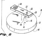
第2図は、第1図の可搬式の超音波治療の複合体の分解した透視図であり、ICUが変換器と分離されて示されるものである。
第3図は、第1および第2図に示される可搬式の超音波治療の複合体であって、複合体を外部皮膚の場所に近接して装着するためのストラップおよび1つのストラップと一体にされた電池パックを有するもの、の透視図である。
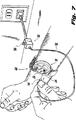
第4図は、治療の期間第3図の可搬式の超音波治療の複合体を装着している患者の透視図である。
第5図は、第1および第2図のICUの回路のブロック図である。
第6図は、第1および第2図のICU用の外部治療制御回路の回路構成のブロック図である。
第7図は、第3図の可搬式の超音波治療の複合体を装着する患者と外部治療制御回路を包含する可搬式の制御ユニットの透視図である。
第8図は、本発明による可搬式の超音波治療の複合体の代替の好適な具体例、および同じ基板上に収容される集積回路と超音波変換器の透視図である。
第9図は、第1図の超音波治療の複合体と集積回路ユニットに近接して装着される電池ホルダの透視図である。
第10図は、第8図の超音波治療の複合体と集積回路ユニットに近接して装着される電池ホルダの透視図である。
好適実施例の詳細な説明
本発明の超音波治療の装置は、超音波を用いて傷病を療法的に治療するために用いられる。筋肉と骨格の傷病の治療に伝統的な強調が置かれてきたが、静脈の潰瘍を包含する他の傷病も考慮される。該装置は可搬式の超音波治療の複合体を包含し、該複合体は変換器の部分に近接し電子工学的に連係する集積回路ユニット(“ICU”)を包含する。該ICUは信号発生回路を収容し、該信号発生回路は駆動信号を電子的リンクを通して変換器に供給する。駆動信号は内部のタイマ回路によりイネーブルおよびディスエーブルにされる。タイマはICU上の通信インターフェイスを通して受信される外部治療制御回路からの信号により制御される。作動に際し、変換器の作動面は、傷病の区域に対応する外部皮膚の場所に近接して位置させられる。外部治療制御回路はタイマを設定するために用いられ、信号発生回路がイネーブルにされる。次いで信号発生回路は変換器用駆動信号を生成し、該変換器は超音波療法の治療を外部の場所に施す。
図面を参照すると、特に第1図には、本発明の可搬式の超音波治療の複合体10が示される。超音波治療の複合体10はICU20に結合された超音波変換器12を包含する。圧電形変換器12は、ウエハーのような形状を有し、圧電形変換器12の作動面14の反対側にはICU20が装着されている。(変換器12の“作動面”は、その面から超音波が変換器12により送出されるところの面であると規定される。変換器12の“裏側”は、変換器12の作動面14の反対側であると規定される。)
ICU20は、ジャック22として示され外部電源54から電力を受ける第1のインターフェイスを有する。(電力は、電源54から導体52およびジャック22で受けるプラグ50を通って供給される。)ICU20はまた、ジャック24として示され制御信号を後述される外部治療制御回路から受信する第2のインターフェイスを有する。
第2図を参照すると、変換器12はICU20から離隔されて示されている。変換器12の裏側に近接するICU20の面は、一連の電子工学的ピン26を有し、該電子工学的ピンは変換器12の裏面上のレセプタ16で受ける。後述されるように、これは、ICU20より発生させられ変換器12へ送出される駆動信号用の電子工学的リンクを提供する。
第3図は、ユニット60の一部としての本発明の超音波治療の複合体10を示し、該複合体は変換器12を傷病に対応する外部皮膚の場所に近接して位置させるよう、使用されることが可能である。プラスチックのフレーム61は、変換器12の周囲を確実に覆う。ストラップの区分62A,62Bはフレーム61とインターフェイスし、1つのストラップの区分62Bは、電力をICU20へ供給するリチウム電池用の電池ホルダ64を支持する。(電力コード66は電池ホルダ64に接続され、電力コード66のプラグ68はICU20のジャック22で受ける。電力コード66とICU20の間のその他のインターフェイスの方法で代替することが可能であり、電力コード66の一端をICU20へ直接にハードワイヤ接続することも代替の方法に包含される。)第4図は第3図のユニット60が患者の腕に取付けられることをあらわし、それにより変換器12の作動面14は腕の外側の皮膚に近接して位置させられる。作動させられると、以下に記述されるように、変換器は、患者の腕へ、その場所において超音波療法の治療を提供することが可能である。
第5図を参照すると、ICU20の信号発生回路の1つの具体例のブロック図が示されている。信号発生回路は無線周波数発振器28を包含し、該発振器は変調器30を通して変換器駆動部32へ接続される。変換器駆動部32は変換器12を励振する。(変換器駆動部32は第2図に示されるピン26およびレセプタ16を通って変換器12に接続される。)信号発生回路はタイマ34によりイネーブルにされる。タイマ34は、例えばICU20への電力入力部と内部要素の1つまたは複数の間の電子的スイッチであることが可能であり、このことはタイマ34と無線周波数発振器28、変調器30、および変換器駆動部32の間の破線で示されるようなものである。タイマ34は、以下に記述されるように外部治療制御回路から受信される治療制御信号70により設定される。
前述されるように、一般的に、無線周波数発振器28は250kHzと10MHzの間の超音波搬送波周波数を発生する。搬送波周波数は比較的低い周波数の信号(例えば5Hzないし10kHz)で変調器30により変調される。変調された搬送波周波数は変換器駆動部32へ入力され、該変調器駆動部は変換器12への駆動信号を発生させる。変換器12は治療に効果的な低強度の音波信号(例えば100mW/cm2より小)を送出する。
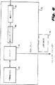
第6図は、ICU20のタイマ34のために治療制御信号70を発生する外部治療制御回路70のブロック図をあらわす。第6図の外部治療制御回路72はメモリ76(例えばRAMおよびROM)を有するプロセッサ74を包含し、該メモリは、プロセッサの作動そして結果的にICU20の作動を制御する記憶されたプログラム(例えばシステムプログラムおよびアプリケーションプログラム)を有する。プロセッサ74はマイクロプロセッサ、例えばIntel(登録商標)80/x86ファミリーのマイクロプロセッサ)、であり、またはプロセッサ74は内部メモリを有するマイクロコントローラであることが可能である。プロセッサ74は特定の患者の超音波治療の時間を制御することに利用される。超音波治療を作動させるためプロセッサ74は患者用に調節された治療制御信号70をICU20のタイマ34へインターフェイス22を通して送出する(第5図参照)。治療制御信号70は適切な治療時間についてタイマ34を設定し、このことは前述されるようにICU20の信号発生回路をイネーブルにする。治療時間が満了すると、タイマは信号発生回路をディスエーブルにする。
第6図の外部治療制御回路72は可搬式の制御ユニットに特に適しており、該可搬式の制御ユニットは超音波の複合体を作動させるため各患者について予めプログラムされ割当てられる。通信インターフェイス82は、通信ポート84とプロセッサ74の間に接続され、例えば外部のコンピュータと通信するために提供される。したがって、メモリ76は患者への割当てに先立って予めプログラムされることが可能であり、それによりプロセッサ74により治療制御信号70により送出される治療時間は特定の患者に適切なものである。(代表的な治療時間は1分と55分の間の範囲であることが可能であり、ただし10分ないし20分のオーダーの治療が代表的である)。通信インターフェイス82は、直列のインターフェイス例えばRS−232のインターフェイス、並列のインターフェイス、またはモデムであることが可能である。
第7図は、第6図の外部治療制御回路を収容する可搬式の制御ユニット90を示し、該制御ユニットはここに示される患者の治療の要求について予めプログラムされている。ここに示される制御ユニット90は、第1図および第2図の超音波治療の複合体を作動させるが、該超音波治療の複合体は第3図のユニット60と合体されており第5図の信号発生回路を有する。超音波治療を開始するに際し、患者は制御ユニット90からの導体92の接続プラグ94により制御インターフェイスを完成させる。患者はボタン96を押下することにより外部治療制御回路(第6図に示される)を作動させ、プロセッサ74は治療制御信号70をICU20のタイマ34(第5図に示される)へ転送する。前述されるように、それによりICU20の信号発生回路はタイマにより設定される期間の間イネーブルにされ、規定された超音波治療が施される。ユニット60がいったんイネーブルにされるとプラグ24は取外されることが可能であり、それにより患者は完全に動くことが可能になる。
第7図に示されるようにICU20のための治療制御信号70を生成するために個別の制御ユニット90を患者に割当てる代りに、外部治療制御回路は遠隔の集中データ処理センタに存在することが可能である。該センタは電話ラインに連係されることが可能であり、患者は電話呼出しを行って外部治療制御回路へのアクセスを行い治療制御信号70のICU20へのダウンロードを作動させる。電話呼出しを行った後、患者は例えば識別コードを電話機のタッチパッドにより入力することが可能であり、それによりデータセンタに対し患者のデータのメモリにおける場所を確認し、その特定の患者についての治療制御信号70を発生させるデータ処理を開始させることが可能である。超音波の複合体のICU20における制御インターフェイス(第5図参照)は、例えば標準の電話ジャックであることが可能である。識別コードを入力した後、患者はプラグを電話機から取外し、複合体20におけるジャックインターフェイス24に挿入する。次いで治療制御信号70は遠隔の外部治療制御回路から送出されることが可能であり、ICU20の信号発生回路を作動させることが可能である。
前述されるように、超音波治療の複合体は、第1および第2図に示される形態に限定されない。第8図に示される代りの好適な実施例において変換器112のセラミックの圧電形ウエハの裏側は超音波治療の複合体100のICU120のための基板を形成する。ICU120の信号発生回路は第5図に示されるものと同じであることが可能であるが、変換器駆動部と変換器の間のインターフェイスはシリコンウエーハの内部にあることが可能である。第8図に示されるように、電力インターフェイス122と制御インターフェイス124はまた、変換器基板の裏面とICU120の信号発生回路の間に直接にハードワイヤ接続されることが可能である。プラスチックのキャップ126が、ICU120の信号発生回路を覆うことに用いられることが可能である。
超音波の複合体をさらによりコンパクトにするために、電池ホルダがICUに近接して置かれることが可能である。第9図において、第1および第2図の複合体10は、ICU20に近接して装着されるリチウム電池のホルダ55とともに示されている。この実施例において、電池とICU20の信号発生回路の間の電力インターフェイスはハードワイヤ接続され、したがって第1および第2図の電力インターフェイスをなくすことが可能である。第10図において、第8図の超音波治療の複合体の代りの類似の具体例が示されており、その場合に電池ホルダ155は変換器とICUを収容するシリコンウエーハの裏面に近接して装着されている。
本明細書に開示される本発明の種々の実施例に対し種々の変形が、本発明の精神および範囲を逸脱することなく、なされ得ることが理解されるであろう。例えば超音波治療の複合体、ICU、および変換器の種々の形状、および構成材料の種々の形式が考慮される。また、超音波変換器を励振するために用いられる要素の形態に種々の変形がなされることが可能である。したがって以上の記述は発明を限定するものと解釈されるべきではなく、単に発明の好適な実施例を提示するものと解釈されるべきである。技術の熟達者は提示される特許請求の範囲により規定される本発明の範囲および精神内において他の変形を想像するであろう。Background of the Invention Field of the Invention The present invention relates to a device you therapeutically therapy of injuries using ultrasound. More particularly, the present invention relates to devices utilizing bone injuries or a variety of muscle and skeleton of injuries and / or signal generators portable you a therapy problems and converter.
2. The use of ultrasound to the sick description bone of the Related Art therapeutically therapy evaluated are known. Projecting ultrasound pulses with appropriate parameters, such as frequency, pulse repetition rate, and amplitude, at an appropriate external location in close proximity to a bone injury for an appropriate length of time can result in, for example, fractures and bone collapse It has been determined to accelerate the natural healing of. For patients with reduced healing capacity, such as older adults with osteoporosis, ultrasound treatment can accelerate the healing of bone scars, which must be done. This can lead to situations where replacement with a prosthesis is required or the patient is permanently disabled.
US Pat. No. 4,530,360 to Duarte (“Duarte”) describes a basic therapy technique and apparatus for applying ultrasonic pulses from an ultrasonic applicator placed on the skin in a location proximate to a bone injury. Yes. Duarte describes the level of radio frequency signals that generate ultrasound, the level of ultrasound power density, the range of duration of each ultrasound pulse, and the range of frequencies of ultrasound pulses. The length of time for daily treatment is also described. The applicator device described in the '360 patent is connected to a plastic tube that serves as a gripping device for the operator, a radio frequency plug attached to the plastic tube for connection to a radio frequency power source, and an ultrasonic transducer . Has internal wire connection. In order to apply ultrasound pulses during the treatment period, the operator must hold the application device in place by hand until the treatment is complete. As a result, the patient cannot actually move for the duration of the treatment. The longer the treatment period, the more crippled the patient.
Generally, the frequency of an ultrasonic carrier between 250 kHz and 10 kHz combined with a relatively low frequency modulation signal (eg 5 Hz to 10 kHz) and a low intensity sound wave signal (eg less than 100 mW / cm 2 ) Should support and be effective in methods and devices for healing wounds.
Both US Pat. Nos. 5,003,965 and 5,618,162 are granted to Talish and Lifshey (represented as “Talish '965” and “Talish' 162”, respectively) and describe an ultrasound delivery system, In that case, both the radio frequency generator and the transducer are part of a modular applicator unit that is placed on the skin. A signal that controls the duration of the ultrasonic pulse and the frequency of the pulse repetition is generated remotely from the application device. Talish '965 and Talish' 162 also describe attachment devices that attach the applicator unit so that the working surface is close to the skin location. In Talish '965 and Talish' 162, the skin is surrounded by a cast, whereas in Talish and Lifshey, US Pat. No. 5,121,160 (Talish '160), the attachment device is on an uncovered body part. (Ie, without using a bandage or other medical packaging). Talish '160 also describes various improvements to the applicator unit.
Durate, Talish '965, Talish' 162, and Talish '160 are all incorporated herein by reference.
Systems described in these patents, although the bone injuries are related to a method and apparatus therapies for treating ultrasonically these patents, to allow the movement of the individuals in the treatment period is maximized do not disclose the internal signal generator and transducer for. Accordingly , there is a need for a device that optimizes patient movement during the period of ultrasound therapy treatment.
Ultrasonic therapy apparatus SUMMARY <br/> The present invention is used to therapeutically treat the sick using ultrasound. The apparatus includes a complex of treatment with ultrasound (composite), the complex, provides excitation oscillation signal for ultrasonic transducers in the combination. The portable complex is configured to be worn by a patient proximate to a treatment location and includes a treatment timed control circuit. The complex may have a power interface and a control interface for an external power source, the control interface appropriately actuating the elements of the complex to provide daily ultrasound therapy. (Alternatively, the complex may have a power that is integrated.) In operation, the complex, is positioned in close proximity to the location of the skin of the outer portion of the corresponding transducer victim is vibration Ma励predetermined period.
Accordingly, the present invention can encompass a transducer and ultrasonic therapy complex you provided an integrated circuit unit located in proximity to the transducer. Ultrasonic therapy complex also includes a signal generating circuit that is housed on the integrated circuit unit for generating a driving signal for the transducer, and a driving interface between the signal generation circuit and the transducer. In operation, the drive signal generated by the signal generating circuit is delivered to the transducer by the interface, thereby driving the transducer to generate ultrasonic therapy.
Preferably, the complex has an integrated circuit unit located in proximity of the transducer ( "ICU"), the ICU provides excitation oscillation signal to support a signal generator circuit converter. The control interface on the ICU can support a data link between the signal generation circuit and the external therapy control circuit. When the data link is performed to access to the control interface, the external treatment control circuitry provides appropriate control information to the signal generating circuit, therefore, causes actuation of the therapeutic ultrasound therapy among certain period.
In a preferred embodiment of the present invention, ICU is a chip based on individual silicon, the chip is mounted in a non-working surface of the wafer of ceramic piezoelectric type transducer (back surface). The ICU has external conductor receptor and interfaces on the transducer, thus driving signal generated by the signal generation circuit on the chip to provide an electronic interconnection as it is possible to drive the transducer. In a preferred embodiment of the alternative, the ICU is incorporated into the back side of the ceramic transducer wafer, the wafer provides a substrate for signal generation circuit. In an embodiment of such an alternative, an electronic linkage between the signal generator and the transducer can be located inside the ceramic wafer.
Preferred alternative embodiments of the present invention therefore encompasses ultrasound therapy for complex you includes a configured transducers by a portion of the piezoelectric-type substrate, said transducer for transmission of ultrasonic therapy Having a working surface. Formed a single integrated circuit in a part of the piezoelectric type substrate, the integrated circuit has a signal generation circuit for driving the signal generator of the transducer. One drive surface is formed between the signal generator and the transducer in the substrate, upon actuation, the drive signal generated by the signal generating circuit is sent to the transducer by the interface, for therapy in actuating surface drives the transducer Ultrasound is generated .
The present invention also encompasses a system for treatment by ultrasonic treatment, the system comprises a complex of ultrasonic treatment, the complex is adjacent to the transducer therewith electronically interface signal generation circuit Including an integrated circuit. Signal generation circuit is configured to provide to the transducer drive signals through the interface, to generate ultrasonic therapy. One external therapy control circuit spaced from the complex is provided and configured to generate control signals for the integrated circuit. A control interface between the external therapy control circuit and the integrated circuit is included, and control signals generated by the external therapy control circuit are sent to the integrated circuit.
Signal generation circuit is preferably encompasses a timer to activation and deactivation of the radio frequency oscillator and modulator, and a signal generating circuit that interfaces with the drive unit. The external therapy control circuit helps to set a timer for the appropriate therapy time interval when a data link is formed across the control interface. The external therapy control circuit may comprise a processor that generates a control signal for setting the timer. The control signal sent to the timer can be generated by the processor using data stored in memory for a particular patient, or generated by data input to the processor by the keyboard. Is possible.
The external therapy control circuit can be combined with the ultrasound therapy complex, for example, in a portable control unit defined for the patient. The control unit can be preprogrammed based on the required treatment for a particular patient. The patient can complete the data link between the control unit and the control interface of the ICU and then activate the control unit. A control signal from the control unit can be generated and sent to the timer of the signal generation circuit, thus enabling the circuit to operate and provide ultrasound therapy for a specified period of time. is there.
Alternatively, the external treatment control circuit can be located remotely from the patient and a data link with the ICU can be provided, for example, by a telephone line. In that case, the communication interface of the ICU can be a standard telephone jack.
[Brief description of the drawings]
Preferred embodiments of the present invention are described below with reference to the drawings, which are as follows:
FIG. 1 is a perspective view of a portable ultrasound therapy complex and external power source according to the present invention , which illustrates an integrated circuit unit (“ICU”) and an ultrasound transducer . It is.
Figure 2 is an exploded perspective view of a complex ultrasound treatment of transportable Figure 1, in which the ICU shown separated transducer.
FIG. 3 is a portable ultrasound therapy complex shown in FIGS. 1 and 2, which is integrated with a strap for attaching the complex in close proximity to an external skin location and one strap. It is a perspective view of what has the made battery pack.
FIG. 4 is a perspective view of a patient wearing the portable ultrasound therapy complex of FIG. 3 during the treatment period.
Figure 5 is a block diagram of ICU circuit of the first and second views.
6 is a block diagram of a circuit configuration of the external treatment control circuitry for the ICU of the first and second views.
FIG. 7 is a perspective view of a portable control unit including a patient wearing the portable ultrasound therapy complex of FIG. 3 and an external therapy control circuit.
8 is a perspective view of the present invention by a portable preferred embodiment of an alternative ultrasonic treatment composite, and the integrated circuit and ultrasonic transducer housed on the same substrate.
FIG. 9 is a perspective view of the ultrasonic treatment complex of FIG. 1 and a battery holder mounted in the vicinity of the integrated circuit unit.
FIG. 10 is a perspective view of the battery holder mounted in the vicinity of the ultrasonic therapy complex and integrated circuit unit of FIG.
Suitable ultrasonic treatment apparatus DETAILED DESCRIPTION OF THE INVENTION The embodiment is used to treat injuries therapeutically using ultrasound. While traditional emphasis has been placed on the treatment of muscle and skeletal wounds, other wounds including venous ulcers are also considered. The device includes a portable ultrasound therapy complex, which includes an integrated circuit unit ("ICU") in close proximity to and electronically associated with the transducer portion. The ICU houses signal generator, the signal generator is supplied to the transducer drive signals through electronic links. The drive signal is enabled and disabled by an internal timer circuit. The timer is controlled by a signal from an external treatment control circuit received through a communication interface on the ICU. In operation, the working surface of the transducer is positioned in close proximity to the external skin location corresponding to the diseased area. The external therapy control circuit is used to set the timer and the signal generation circuit is enabled . Then the signal generating circuit generates a driving signal for the transducer, the transducer is subjected to a treatment of ultrasonic therapy to an external location.
Referring now to the drawings, and particularly to FIG. 1, there is shown a portable
ICU20 has a first interface Ru receive power from an external power source 54 is shown as a
Referring to Figure 2, the
FIG. 3 shows the
Referring to FIG. 5, block diagram of one embodiment of the signal generating circuit ICU20 is shown. Signal generating circuit includes a
As described above, in general,
Figure 6 represents a block diagram of the external
The external
FIG. 7 shows a portable control unit 90 containing the external treatment control circuit of FIG. 6, which is pre-programmed for the patient treatment requirements shown here. The control unit 90 shown here operates the ultrasound therapy complex of FIGS. 1 and 2, which is combined with the
Instead of assigning a separate control unit 90 to the patient to generate a
As mentioned above, the ultrasound therapy complex is not limited to the form shown in FIGS. In the alternative preferred embodiment shown in FIG. 8, the back side of the ceramic piezoelectric wafer of the
To make the ultrasound complex even more compact, a battery holder can be placed in close proximity to the ICU. In FIG. 9, the composite 10 of FIGS. 1 and 2 is shown with a
It will be understood that various modifications can be made to the various embodiments of the invention disclosed herein without departing from the spirit and scope of the invention. For example, ultrasonic treatment composite, ICU, and various forms of various shapes, and the material of the transducer is considered. It is also possible that various modifications may be made in the form of elements used to excite the ultrasonic transducer. Therefore, the above description should not be construed as limiting the invention, but merely as exemplifying preferred embodiments of the invention. Those skilled in the art will envision other modifications within the scope and spirit of the present invention as defined by the claims presented.
Claims (16)
(b)該圧電変換器の超音波が放射される側面と反対側の側面に実装されている集積回路ユニット(20)であって、
該変換器(12)の駆動信号発生用の信号発生回路(28,30,32,34)と、
該信号発生回路(28,30,32,34)とインターフェイスし該信号発生回路(28,30,32,34)を制御するタイマ(34)であって、外部制御源(70)から受信する制御信号により作動させることができる、タイマ(34)と、
該外部制御源(70)と、
該外部制御源(70)から制御信号を受信する制御インターフェイス(24)と、を備え,該信号発生回路と該タイマと該制御インターフェイスを収容する前記集積回路ユニット(20)と、
(c)該信号発生回路(28,30,32,34)と該変換器(12)の間の駆動インターフェイス(16,26)と、を具備する超音波療法用複合体であって、
該信号発生回路(28,30,32,34)は駆動信号を発生することが可能であり、該駆動インターフェイス(16,26)は該駆動信号を伝送可能であり、該駆動信号は、療法用超音波を放射することが可能な該変換器(12)を駆動可能である超音波療法用複合体。 And (a) a piezoelectric transducer (12),
(B) an integrated circuit unit (20) mounted on the side surface opposite to the side surface on which the ultrasonic wave is emitted of the piezoelectric transducer ,
The transducer and signal generating circuit for driving signal generation (12) (28, 30, 32, 34),
A timer (34) that interfaces with the signal generation circuit (28, 30, 32, 34) and controls the signal generation circuit (28, 30, 32, 34), and receives control from the external control source (70) A timer (34), which can be activated by a signal,
The external control source (70);
A control interface (24) for receiving a control signal from the external control source (70), the integrated circuit unit (20) accommodating the signal generation circuit, the timer, and the control interface;
(C) an ultrasonic therapy complex comprising driving the interface (16, 26), the between the signal generating circuit (28, 30, 32, 34) and said transducer (12),
The signal generation circuit (28, 30, 32, 34) can generate a drive signal, the drive interface (16, 26) can transmit the drive signal, and the drive signal is used for therapy. A complex for ultrasonic therapy capable of driving the transducer (12) capable of emitting ultrasonic waves .
(b)集積回路ユニット(20)であって、
該変換器(12)の駆動信号発生用の信号発生回路(28,30,32,34)と、
該信号発生回路(28,30,32,34)とインターフェイスし該信号発生回路(28,30,32,34)を制御するタイマ(34)であって、外部制御源(70)から受信する制御信号により作動させることができる、タイマ(34)と、
該外部制御源(70)と、
該外部制御源(70)から制御信号を受信する制御インターフェイス(24)と、を備え,該信号発生回路と該タイマと該制御インターフェイスを収容し、該変換器(12)は前記集積回路用の基板を形成する圧電基板によって形成される前記集積回路ユニット(20)と、
(c)該信号発生回路(28,30,32,34)と該変換器(12)の間の駆動インタフェース(16,26)と、を具備する超音波療法用複合体であって、
該信号発生回路(28,30,32,34)は駆動信号を発生することが可能であり、該駆動インターフェイス(16,26)は該駆動信号を伝送可能であり、該駆動信号は、療法用超音波を放射することが可能な該変換器(12)を駆動可能である超音波療法用複合体。 (A) the converter (12) ;
(B) an integrated circuit unit (20),
A signal generation circuit (28, 30, 32, 34) for generating a drive signal of the converter (12);
A timer (34) that interfaces with the signal generation circuit (28, 30, 32, 34) and controls the signal generation circuit (28, 30, 32, 34), and receives control from the external control source (70) A timer (34), which can be activated by a signal,
The external control source (70);
A control interface (24) for receiving a control signal from the external control source (70), containing the signal generation circuit, the timer, and the control interface, and the converter (12) for the integrated circuit The integrated circuit unit (20) formed by a piezoelectric substrate forming a substrate;
(C) a composite for ultrasonic therapy comprising a drive interface (16, 26) between the signal generation circuit (28, 30, 32, 34) and the transducer (12),
The signal generation circuit (28, 30, 32, 34) can generate a drive signal, the drive interface (16, 26) can transmit the drive signal, and the drive signal is used for therapy. A complex for ultrasonic therapy capable of driving the transducer (12) capable of emitting ultrasonic waves.
(b)該複合体(10)から隔離された外部治療制御回路(72)であって、集積回路上のタイマを駆動可能な制御信号を発生するよう構成される外部治療制御回路(72)、および
(c)該外部治療制御回路(72)と該集積回路(28,30,32,34)の間の制御インターフェイスであって、該外部治療制御回路(72)により発生する該制御信号を該集積回路(28,30,32,34)へ送出する制御インターフェイスと、を具備する超音波療法システム。(A) the ultrasonic therapy complex (10) according to claim 1 or 2 , and
(B) an external therapy control circuit (72) isolated from the complex (10), the external therapy control circuit (72) configured to generate a control signal capable of driving a timer on the integrated circuit; and (c) a control interface between the external treatment control circuitry (72) and the integrated circuit (28, 30, 32, 34), said control signal generated by the external treatment control circuitry (72) ultrasonic care Hoshi stem comprising a control interface for sending to said integrated circuit (28, 30, 32, and 34).
Applications Claiming Priority (3)
| Application Number | Priority Date | Filing Date | Title |
|---|---|---|---|
| US4470997P | 1997-04-18 | 1997-04-18 | |
| US60/044,709 | 1997-04-18 | ||
| PCT/US1998/007531 WO1998047568A1 (en) | 1997-04-18 | 1998-04-16 | Apparatus for ultrasonic bone treatment |
Publications (3)
| Publication Number | Publication Date |
|---|---|
| JP2001520558A JP2001520558A (en) | 2001-10-30 |
| JP2001520558A5 JP2001520558A5 (en) | 2005-12-02 |
| JP4073967B2 true JP4073967B2 (en) | 2008-04-09 |
Family
ID=21933888
Family Applications (1)
| Application Number | Title | Priority Date | Filing Date |
|---|---|---|---|
| JP54613698A Expired - Fee Related JP4073967B2 (en) | 1997-04-18 | 1998-04-16 | Ultrasound bone treatment device |
Country Status (11)
| Country | Link |
|---|---|
| US (1) | US6322527B1 (en) |
| EP (1) | EP0975391B1 (en) |
| JP (1) | JP4073967B2 (en) |
| KR (1) | KR100726959B1 (en) |
| AT (2) | ATE283095T1 (en) |
| AU (1) | AU743499B2 (en) |
| CA (1) | CA2285593C (en) |
| DE (2) | DE69821345T2 (en) |
| DK (2) | DK1350540T3 (en) |
| ES (2) | ES2214705T3 (en) |
| WO (1) | WO1998047568A1 (en) |
Families Citing this family (47)
| Publication number | Priority date | Publication date | Assignee | Title |
|---|---|---|---|---|
| GB9617749D0 (en) * | 1996-08-23 | 1996-10-02 | Young Michael J R | Improved apparatus for ultrasonic therapeutic trteatment |
| US7789841B2 (en) | 1997-02-06 | 2010-09-07 | Exogen, Inc. | Method and apparatus for connective tissue treatment |
| CA2377441A1 (en) * | 1999-06-14 | 2000-12-21 | Exogen, Inc. | Self-contained ultrasound applicator |
| IL131623A0 (en) | 1999-08-27 | 2001-01-28 | Dan Weiss | Apparatus to couple ultrasonic energy to catheters and other transdermal medical devices |
| KR100353388B1 (en) * | 2000-06-30 | 2002-09-18 | 주식회사 싸이버메딕 | The programmable electrical stimulator of portable |
| US6601581B1 (en) | 2000-11-01 | 2003-08-05 | Advanced Medical Applications, Inc. | Method and device for ultrasound drug delivery |
| US6618620B1 (en) | 2000-11-28 | 2003-09-09 | Txsonics Ltd. | Apparatus for controlling thermal dosing in an thermal treatment system |
| US6761729B2 (en) | 2000-12-22 | 2004-07-13 | Advanced Medicalapplications, Inc. | Wound treatment method and device with combination of ultrasound and laser energy |
| US6533803B2 (en) | 2000-12-22 | 2003-03-18 | Advanced Medical Applications, Inc. | Wound treatment method and device with combination of ultrasound and laser energy |
| US8235919B2 (en) | 2001-01-12 | 2012-08-07 | Celleration, Inc. | Ultrasonic method and device for wound treatment |
| US7914470B2 (en) | 2001-01-12 | 2011-03-29 | Celleration, Inc. | Ultrasonic method and device for wound treatment |
| US6623444B2 (en) | 2001-03-21 | 2003-09-23 | Advanced Medical Applications, Inc. | Ultrasonic catheter drug delivery method and device |
| US6478754B1 (en) | 2001-04-23 | 2002-11-12 | Advanced Medical Applications, Inc. | Ultrasonic method and device for wound treatment |
| JP4660024B2 (en) * | 2001-06-26 | 2011-03-30 | 帝人株式会社 | MMP activity lowering apparatus and method |
| EP1466565A4 (en) * | 2002-01-18 | 2010-04-21 | Teijin Ltd | Method of treating osteochondritis and apparatus for treating osteochondritis |
| US8409099B2 (en) * | 2004-08-26 | 2013-04-02 | Insightec Ltd. | Focused ultrasound system for surrounding a body tissue mass and treatment method |
| US20110128726A1 (en) * | 2005-05-26 | 2011-06-02 | Kinaptic, LLC | Thin film energy fabric with light generation layer |
| US20110130813A1 (en) * | 2005-05-26 | 2011-06-02 | Kinaptic, LLC | Thin film energy fabric for self-regulating heated wound dressings |
| US20110127248A1 (en) * | 2005-05-26 | 2011-06-02 | Kinaptic,LLC | Thin film energy fabric for self-regulating heat generation layer |
| US20110128686A1 (en) * | 2005-05-26 | 2011-06-02 | Kinaptic, LLC | Thin film energy fabric with energy transmission/reception layer |
| US7494945B2 (en) * | 2005-05-26 | 2009-02-24 | Energy Integration Technologies, Inc. | Thin film energy fabric |
| US20080109941A1 (en) * | 2005-05-26 | 2008-05-15 | Energy Integration Technologies, Inc. | Thin film energy fabric integration, control and method of making |
| US7713218B2 (en) | 2005-06-23 | 2010-05-11 | Celleration, Inc. | Removable applicator nozzle for ultrasound wound therapy device |
| US7785277B2 (en) | 2005-06-23 | 2010-08-31 | Celleration, Inc. | Removable applicator nozzle for ultrasound wound therapy device |
| CN101313354B (en) | 2005-11-23 | 2012-02-15 | 因赛泰克有限公司 | Hierarchical switching in ultra-high density ultrasound array |
| US20070249938A1 (en) * | 2006-04-20 | 2007-10-25 | Donald J. Shields | Systems, devices, and methods employing therapeutic ultrasound of living tissues |
| US7431704B2 (en) * | 2006-06-07 | 2008-10-07 | Bacoustics, Llc | Apparatus and method for the treatment of tissue with ultrasound energy by direct contact |
| US8562547B2 (en) | 2006-06-07 | 2013-10-22 | Eliaz Babaev | Method for debriding wounds |
| US8078283B2 (en) | 2006-06-20 | 2011-12-13 | Ebr Systems, Inc. | Systems and methods for implantable leadless bone stimulation |
| JP2009545416A (en) | 2006-08-04 | 2009-12-24 | オセテチ エス エル | Biomechanical stimulator and method for bone regeneration |
| CN101522263A (en) * | 2006-08-25 | 2009-09-02 | 艾拉兹·巴巴耶夫 | Portable ultrasound device for the treatment of wounds |
| US8491521B2 (en) | 2007-01-04 | 2013-07-23 | Celleration, Inc. | Removable multi-channel applicator nozzle |
| US8251908B2 (en) | 2007-10-01 | 2012-08-28 | Insightec Ltd. | Motion compensated image-guided focused ultrasound therapy system |
| US20100016911A1 (en) | 2008-07-16 | 2010-01-21 | Ebr Systems, Inc. | Local Lead To Improve Energy Efficiency In Implantable Wireless Acoustic Stimulators |
| US8425424B2 (en) | 2008-11-19 | 2013-04-23 | Inightee Ltd. | Closed-loop clot lysis |
| US8617073B2 (en) | 2009-04-17 | 2013-12-31 | Insightec Ltd. | Focusing ultrasound into the brain through the skull by utilizing both longitudinal and shear waves |
| US9623266B2 (en) | 2009-08-04 | 2017-04-18 | Insightec Ltd. | Estimation of alignment parameters in magnetic-resonance-guided ultrasound focusing |
| WO2011024074A2 (en) | 2009-08-26 | 2011-03-03 | Insightec Ltd. | Asymmetric phased-array ultrasound transducer |
| US8661873B2 (en) | 2009-10-14 | 2014-03-04 | Insightec Ltd. | Mapping ultrasound transducers |
| ES2928669T3 (en) | 2009-12-31 | 2022-11-22 | Zetroz Systems Llc | Ultrasound Docking Device |
| US9852727B2 (en) | 2010-04-28 | 2017-12-26 | Insightec, Ltd. | Multi-segment ultrasound transducers |
| US8932237B2 (en) | 2010-04-28 | 2015-01-13 | Insightec, Ltd. | Efficient ultrasound focusing |
| US9981148B2 (en) | 2010-10-22 | 2018-05-29 | Insightec, Ltd. | Adaptive active cooling during focused ultrasound treatment |
| JP6168883B2 (en) * | 2013-07-04 | 2017-07-26 | 伊藤超短波株式会社 | Probe fixture and ultrasonic therapy device |
| WO2015080901A1 (en) | 2013-11-26 | 2015-06-04 | Celleration Inc. | Systems and methods for producing and delivering ultrasonic therapies for wound treatment and healing |
| ES2636822B1 (en) | 2016-03-03 | 2018-06-07 | Norcri Invest, S.L. | System and method for the ultrasonic treatment of fractures, osteo-musculoskeletal lesions, post-surgical pain and osteonecrosis in the field of medicine and veterinary medicine and their uses |
| US10362982B2 (en) | 2017-04-28 | 2019-07-30 | Warsaw Orthopedic, Inc. | Spinal implant system and method |
Family Cites Families (9)
| Publication number | Priority date | Publication date | Assignee | Title |
|---|---|---|---|---|
| BR8107560A (en) | 1981-11-19 | 1983-07-05 | Luiz Romariz Duarte | ULTRASONIC STIMULATION OF BONE FRACTURE CONSOLIDATION |
| US5211160A (en) | 1988-09-14 | 1993-05-18 | Interpore Orthopaedics, Inc. | Ultrasonic orthopedic treatment head and body-mounting means therefor |
| US5186162A (en) | 1988-09-14 | 1993-02-16 | Interpore Orthopaedics, Inc. | Ultrasonic transducer device for treatment of living tissue and/or cells |
| US5003965A (en) | 1988-09-14 | 1991-04-02 | Meditron Corporation | Medical device for ultrasonic treatment of living tissue and/or cells |
| US5556372A (en) * | 1995-02-15 | 1996-09-17 | Exogen, Inc. | Apparatus for ultrasonic bone treatment |
| CN1155342C (en) * | 1995-02-15 | 2004-06-30 | 艾克索根公司 | Locating method and apparatus |
| US5626554A (en) * | 1995-02-21 | 1997-05-06 | Exogen, Inc. | Gel containment structure |
| US5762616A (en) * | 1996-03-15 | 1998-06-09 | Exogen, Inc. | Apparatus for ultrasonic treatment of sites corresponding to the torso |
| US5997490A (en) * | 1997-02-12 | 1999-12-07 | Exogen, Inc. | Method and system for therapeutically treating bone fractures and osteoporosis |
-
1998
- 1998-04-16 EP EP98915579A patent/EP0975391B1/en not_active Expired - Lifetime
- 1998-04-16 WO PCT/US1998/007531 patent/WO1998047568A1/en active IP Right Grant
- 1998-04-16 ES ES98915579T patent/ES2214705T3/en not_active Expired - Lifetime
- 1998-04-16 CA CA002285593A patent/CA2285593C/en not_active Expired - Fee Related
- 1998-04-16 ES ES03014275T patent/ES2232802T3/en not_active Expired - Lifetime
- 1998-04-16 AT AT03014275T patent/ATE283095T1/en active
- 1998-04-16 AU AU69725/98A patent/AU743499B2/en not_active Ceased
- 1998-04-16 JP JP54613698A patent/JP4073967B2/en not_active Expired - Fee Related
- 1998-04-16 AT AT98915579T patent/ATE258453T1/en not_active IP Right Cessation
- 1998-04-16 DK DK03014275T patent/DK1350540T3/en active
- 1998-04-16 DE DE69821345T patent/DE69821345T2/en not_active Expired - Lifetime
- 1998-04-16 DE DE69827860T patent/DE69827860T2/en not_active Expired - Lifetime
- 1998-04-16 KR KR1019997009752A patent/KR100726959B1/en not_active IP Right Cessation
- 1998-04-16 DK DK98915579T patent/DK0975391T3/en active
-
1999
- 1999-10-18 US US09/420,403 patent/US6322527B1/en not_active Expired - Lifetime
Also Published As
| Publication number | Publication date |
|---|---|
| ATE283095T1 (en) | 2004-12-15 |
| ATE258453T1 (en) | 2004-02-15 |
| EP0975391A1 (en) | 2000-02-02 |
| AU743499B2 (en) | 2002-01-24 |
| DE69827860D1 (en) | 2004-12-30 |
| CA2285593C (en) | 2006-11-21 |
| DK0975391T3 (en) | 2004-06-07 |
| CA2285593A1 (en) | 1998-10-29 |
| ES2214705T3 (en) | 2004-09-16 |
| ES2232802T3 (en) | 2005-06-01 |
| JP2001520558A (en) | 2001-10-30 |
| DE69821345D1 (en) | 2004-03-04 |
| WO1998047568A1 (en) | 1998-10-29 |
| DE69827860T2 (en) | 2005-11-24 |
| US6322527B1 (en) | 2001-11-27 |
| EP0975391B1 (en) | 2004-01-28 |
| DK1350540T3 (en) | 2005-04-04 |
| KR100726959B1 (en) | 2007-06-14 |
| DE69821345T2 (en) | 2004-09-30 |
| AU6972598A (en) | 1998-11-13 |
| KR20010006563A (en) | 2001-01-26 |
Similar Documents
| Publication | Publication Date | Title |
|---|---|---|
| JP4073967B2 (en) | Ultrasound bone treatment device | |
| US6432070B1 (en) | Method and apparatus for ultrasonic treatment of reflex sympathetic dystrophy | |
| US6190336B1 (en) | Ultrasonic treatment for wounds | |
| US6436060B1 (en) | Submersible system for ultrasonic treatment | |
| AU1883695A (en) | Apparatus for ultrasonic bone treatment | |
| US8105248B2 (en) | Medical plaster | |
| EP1350540B1 (en) | Apparatus for ultrasonic bone treatment | |
| CA2507452C (en) | Single-use cover system for electromagnetic treatment applicator | |
| JPH0349753A (en) | Ultrasonic treatment aid | |
| AU9795798A (en) | Method and apparatus for ultrasonic treatment of carpal tunnel syndrome | |
| CA2212230C (en) | Apparatus for ultrasonic bone treatment | |
| WO2000076586A1 (en) | Self-contained ultrasound applicator | |
| MXPA97006154A (en) | Apparatus for ultrasonic treatment of the hu |
Legal Events
| Date | Code | Title | Description |
|---|---|---|---|
| A521 | Request for written amendment filed |
Free format text: JAPANESE INTERMEDIATE CODE: A523 Effective date: 20050415 |
|
| A621 | Written request for application examination |
Free format text: JAPANESE INTERMEDIATE CODE: A621 Effective date: 20050415 |
|
| A131 | Notification of reasons for refusal |
Free format text: JAPANESE INTERMEDIATE CODE: A131 Effective date: 20070731 |
|
| A521 | Request for written amendment filed |
Free format text: JAPANESE INTERMEDIATE CODE: A523 Effective date: 20071031 |
|
| TRDD | Decision of grant or rejection written | ||
| A01 | Written decision to grant a patent or to grant a registration (utility model) |
Free format text: JAPANESE INTERMEDIATE CODE: A01 Effective date: 20071225 |
|
| A61 | First payment of annual fees (during grant procedure) |
Free format text: JAPANESE INTERMEDIATE CODE: A61 Effective date: 20080124 |
|
| FPAY | Renewal fee payment (event date is renewal date of database) |
Free format text: PAYMENT UNTIL: 20110201 Year of fee payment: 3 |
|
| R150 | Certificate of patent or registration of utility model |
Free format text: JAPANESE INTERMEDIATE CODE: R150 |
|
| FPAY | Renewal fee payment (event date is renewal date of database) |
Free format text: PAYMENT UNTIL: 20120201 Year of fee payment: 4 |
|
| FPAY | Renewal fee payment (event date is renewal date of database) |
Free format text: PAYMENT UNTIL: 20130201 Year of fee payment: 5 |
|
| FPAY | Renewal fee payment (event date is renewal date of database) |
Free format text: PAYMENT UNTIL: 20140201 Year of fee payment: 6 |
|
| R250 | Receipt of annual fees |
Free format text: JAPANESE INTERMEDIATE CODE: R250 |
|
| R250 | Receipt of annual fees |
Free format text: JAPANESE INTERMEDIATE CODE: R250 |
|
| R250 | Receipt of annual fees |
Free format text: JAPANESE INTERMEDIATE CODE: R250 |
|
| LAPS | Cancellation because of no payment of annual fees |