JP4073907B2 - Paper sheet identification device - Google Patents
Paper sheet identification device Download PDFInfo
- Publication number
- JP4073907B2 JP4073907B2 JP2004331828A JP2004331828A JP4073907B2 JP 4073907 B2 JP4073907 B2 JP 4073907B2 JP 2004331828 A JP2004331828 A JP 2004331828A JP 2004331828 A JP2004331828 A JP 2004331828A JP 4073907 B2 JP4073907 B2 JP 4073907B2
- Authority
- JP
- Japan
- Prior art keywords
- light
- output
- paper sheet
- light receiving
- receiving element
- Prior art date
- Legal status (The legal status is an assumption and is not a legal conclusion. Google has not performed a legal analysis and makes no representation as to the accuracy of the status listed.)
- Expired - Fee Related
Links
- 238000001514 detection method Methods 0.000 claims description 162
- 238000012937 correction Methods 0.000 claims description 104
- 238000003780 insertion Methods 0.000 claims description 66
- 230000037431 insertion Effects 0.000 claims description 66
- 238000004364 calculation method Methods 0.000 claims description 40
- 239000003086 colorant Substances 0.000 claims description 33
- 230000001419 dependent effect Effects 0.000 claims 1
- 239000000976 ink Substances 0.000 description 146
- 238000005259 measurement Methods 0.000 description 97
- 230000003287 optical effect Effects 0.000 description 66
- 238000012545 processing Methods 0.000 description 48
- 238000000034 method Methods 0.000 description 45
- 230000015654 memory Effects 0.000 description 37
- 230000008569 process Effects 0.000 description 25
- 230000032258 transport Effects 0.000 description 15
- 238000013480 data collection Methods 0.000 description 13
- 238000010586 diagram Methods 0.000 description 13
- 230000008859 change Effects 0.000 description 10
- 230000005540 biological transmission Effects 0.000 description 7
- 239000000463 material Substances 0.000 description 5
- 230000007723 transport mechanism Effects 0.000 description 4
- 230000005389 magnetism Effects 0.000 description 3
- 230000035945 sensitivity Effects 0.000 description 3
- 230000006866 deterioration Effects 0.000 description 2
- 239000000428 dust Substances 0.000 description 2
- 230000001678 irradiating effect Effects 0.000 description 2
- 230000007246 mechanism Effects 0.000 description 2
- 230000002265 prevention Effects 0.000 description 2
- 230000004044 response Effects 0.000 description 2
- 230000032683 aging Effects 0.000 description 1
- 230000033228 biological regulation Effects 0.000 description 1
- 230000007547 defect Effects 0.000 description 1
- 238000012850 discrimination method Methods 0.000 description 1
- 230000000694 effects Effects 0.000 description 1
- 238000005516 engineering process Methods 0.000 description 1
- 238000002474 experimental method Methods 0.000 description 1
- 239000002932 luster Substances 0.000 description 1
- 238000004519 manufacturing process Methods 0.000 description 1
- 239000012466 permeate Substances 0.000 description 1
- 238000011160 research Methods 0.000 description 1
- 230000002123 temporal effect Effects 0.000 description 1
- 238000012546 transfer Methods 0.000 description 1
Images


Classifications
-
- G—PHYSICS
- G07—CHECKING-DEVICES
- G07D—HANDLING OF COINS OR VALUABLE PAPERS, e.g. TESTING, SORTING BY DENOMINATIONS, COUNTING, DISPENSING, CHANGING OR DEPOSITING
- G07D7/00—Testing specially adapted to determine the identity or genuineness of valuable papers or for segregating those which are unacceptable, e.g. banknotes that are alien to a currency
- G07D7/06—Testing specially adapted to determine the identity or genuineness of valuable papers or for segregating those which are unacceptable, e.g. banknotes that are alien to a currency using wave or particle radiation
- G07D7/12—Visible light, infrared or ultraviolet radiation
- G07D7/121—Apparatus characterised by sensor details
-
- G—PHYSICS
- G01—MEASURING; TESTING
- G01N—INVESTIGATING OR ANALYSING MATERIALS BY DETERMINING THEIR CHEMICAL OR PHYSICAL PROPERTIES
- G01N21/00—Investigating or analysing materials by the use of optical means, i.e. using sub-millimetre waves, infrared, visible or ultraviolet light
- G01N21/17—Systems in which incident light is modified in accordance with the properties of the material investigated
- G01N21/25—Colour; Spectral properties, i.e. comparison of effect of material on the light at two or more different wavelengths or wavelength bands
- G01N21/255—Details, e.g. use of specially adapted sources, lighting or optical systems
-
- G—PHYSICS
- G01—MEASURING; TESTING
- G01N—INVESTIGATING OR ANALYSING MATERIALS BY DETERMINING THEIR CHEMICAL OR PHYSICAL PROPERTIES
- G01N21/00—Investigating or analysing materials by the use of optical means, i.e. using sub-millimetre waves, infrared, visible or ultraviolet light
- G01N21/17—Systems in which incident light is modified in accordance with the properties of the material investigated
- G01N21/55—Specular reflectivity
-
- G—PHYSICS
- G07—CHECKING-DEVICES
- G07D—HANDLING OF COINS OR VALUABLE PAPERS, e.g. TESTING, SORTING BY DENOMINATIONS, COUNTING, DISPENSING, CHANGING OR DEPOSITING
- G07D7/00—Testing specially adapted to determine the identity or genuineness of valuable papers or for segregating those which are unacceptable, e.g. banknotes that are alien to a currency
- G07D7/003—Testing specially adapted to determine the identity or genuineness of valuable papers or for segregating those which are unacceptable, e.g. banknotes that are alien to a currency using security elements
- G07D7/0034—Testing specially adapted to determine the identity or genuineness of valuable papers or for segregating those which are unacceptable, e.g. banknotes that are alien to a currency using security elements using watermarks
-
- G—PHYSICS
- G07—CHECKING-DEVICES
- G07D—HANDLING OF COINS OR VALUABLE PAPERS, e.g. TESTING, SORTING BY DENOMINATIONS, COUNTING, DISPENSING, CHANGING OR DEPOSITING
- G07D7/00—Testing specially adapted to determine the identity or genuineness of valuable papers or for segregating those which are unacceptable, e.g. banknotes that are alien to a currency
- G07D7/06—Testing specially adapted to determine the identity or genuineness of valuable papers or for segregating those which are unacceptable, e.g. banknotes that are alien to a currency using wave or particle radiation
- G07D7/12—Visible light, infrared or ultraviolet radiation
- G07D7/1205—Testing spectral properties
-
- G—PHYSICS
- G01—MEASURING; TESTING
- G01N—INVESTIGATING OR ANALYSING MATERIALS BY DETERMINING THEIR CHEMICAL OR PHYSICAL PROPERTIES
- G01N21/00—Investigating or analysing materials by the use of optical means, i.e. using sub-millimetre waves, infrared, visible or ultraviolet light
- G01N21/84—Systems specially adapted for particular applications
- G01N21/86—Investigating moving sheets
-
- G—PHYSICS
- G07—CHECKING-DEVICES
- G07D—HANDLING OF COINS OR VALUABLE PAPERS, e.g. TESTING, SORTING BY DENOMINATIONS, COUNTING, DISPENSING, CHANGING OR DEPOSITING
- G07D2207/00—Paper-money testing devices
Description
本発明は、紙葉類識別装置に関し、特に、紙葉類の色識別、透かし識別を行うと共に、紙葉類の片面にのみ印刷された色相インキの微妙な特性を検知し、識別することで紙葉類の真偽を精密に判別する紙葉類識別装置に関する。 The present invention relates to a paper sheet identification device, and in particular, performs color identification and watermark identification of paper sheets, and detects and identifies subtle characteristics of hue ink printed only on one side of a paper sheet. The present invention relates to a paper sheet identification device that accurately discriminates the authenticity of a paper sheet .
近年、高精度なスキャナー、プリンタ及びコンピュータ等の装置の普及により、これらの装置を用いて紙幣、小切手等の有価証券が偽造され悪用されるという問題があり、これら偽造券を確実に識別する方法や装置の提供が望まれている。 In recent years, due to the widespread use of devices such as high-precision scanners, printers, and computers, there is a problem that securities such as banknotes and checks are forged and misused using these devices, and a method for reliably identifying these forged tickets And the provision of devices is desired.
最近では、偽造が複写によるものである場合は、容易に偽であることが識別できる識別方法や識別装置の研究が急速に進められており、また、偽造防止を目的とした種々の抄紙方法や印刷技術が提供され、偽造を困難とする紙幣等が提供されている。
例えば、特許文献1には、同一波長の受光素子を角度を変えて複数配置し、紙幣に照射した光を複数の受光素子で受光し、夫々を比較することで紙幣の凹凸を判別する凹版印刷物とその他の印刷物との識別方法が提案されている。
Recently, when forgery is due to copying, research on identification methods and identification devices that can be easily identified as counterfeit has been promoted rapidly, and various papermaking methods aimed at preventing forgery and Printing technology is provided, and banknotes and the like that make counterfeiting difficult are provided.
For example,
この提案は、対象の印刷物の表面に、一定の検出ラインに沿って、順次、点状の光を照射し、その入射点に立てた仮想法線を中心として入射光と対称となる角度位置付近の複数位置での各受光量の相互関係が、入射点が平坦である場合の相互関係と認められる関係にあるか否かを順次判定し、検出完了後の検出結果が平坦でない場合の関係にあるとの判定が対象の印刷物によって決まる一定の割合を越えた場合に凹版印刷物と判定するような構成としたものである。 This proposal irradiates the surface of the target printed matter sequentially with point-shaped light along a certain detection line, and near the angular position that is symmetric with the incident light around the virtual normal that stands at the incident point. It is sequentially determined whether the correlation between the amounts of received light at a plurality of positions is recognized as a correlation when the incident point is flat, and the relationship when the detection result after detection is not flat is The configuration is such that an intaglio printed material is determined when the determination that it is present exceeds a certain ratio determined by the target printed material.
また、特許文献2には、見る角度によって色相が変わる色相インキを使用した印刷物に対して赤と緑の一組の光を色相インキ部へ照射し、2つの受光角度の異なる受光センサで測定し、色と反射角度の違いから色相インキを判別する印刷物読み取り方法と装置が提案されている。
Further,
この提案は、観測点Aでは、例えば赤色光のフォトセンサ出力が緑色光のフォトセンサ出力よりも大きく、かつ観測点Bではその大小が反転している場合に、被判定印刷物は特定の色相変化インキを使用している正規の印刷物であると判定し、反転が見られない場合は偽物であると判定するような構成としたものである。 In this proposal, for example, when the output of the photosensor for red light is larger than the output of the photosensor for green light at the observation point A and the magnitude is reversed at the observation point B, the print to be judged has a specific hue change. It is determined that it is a regular printed material using ink, and when it is not reversed, it is determined to be a fake.
また、特許文献3には、単一の発光素子の光について反射と透過の両方の光を受光し、透かしを判別する紙幣等の真偽識別装置が提案されている。
Further,
この提案は、紙幣等の透かしのパターンを夫々透過光及び反射光を利用した2つの光学的読取り手段にて読み取り、双方の読み取りデータを比較し、一致するか否かにより、紙幣等の真偽を識別するような構成としたものである。 In this proposal, a watermark pattern such as a banknote is read by two optical reading means using transmitted light and reflected light, and both read data are compared. It is set as the structure which identifies.
また、特許文献4には、紙葉類の上面及び下面の各反射パターンデータを加算したパターンデータと紙葉類の透過パターンデータとの差に基づき紙葉類の上下両面間に介設された偽造防止ストライプを検知し、紙葉類の真偽判別を行うように構成された紙葉類の認識装置が提案されている。
ところで、上記提案の特許文献1では、所定照射光による紙幣表面反射光を角度を変えて受光し、夫々を比較した判定結果の割合が規定値以上であるか否かで紙幣の凹凸を判別する方法が開示され、特許文献2では、赤と緑の一組の光を色相インキ部へ照射し、2つの受光角度の異なる受光センサで測定した各色の受光量に反転が見られるか否かにより色相インキを判別する方法が開示されている。
By the way, in
また、特許文献3には、単一発光素子の発光による反射と透過の両方の光を受光して透かしを判別する方法が開示され、特許文献4には、紙葉類の上下面の各反射パターンデータを加算したパターンデータと紙葉類の透過パターンデータとの差に基づき紙葉類の上下両面間に介設された偽造防止ストライプを検知する方法が開示されている。
しかしながら、上記特許文献1乃至特許文献4で示される提案には、色相インキの一種であるパールインキ(視角によりパール光沢のある半透明な模様が浮かび上がるようなインキ)がパールインキの種類(メーカ等の違い等)によって視角により変化する色が異なる、またはパールインキに照射する光の波長や照射角度によって、その反射光の受光出力が異なるようなパールインキの微妙な特性を検知して紙葉類に印刷されたパールインキを精密に識別する方法は提案されていない。
However, in the proposals shown in
また、公知の紙葉類識別方法によるセンサー(反射型光センサーと透過型光センサー)配置の方法で紙葉類の透かしや色合いを識別し、紙葉類の片面にしか印刷されていないパールインキ(色相インキ)を識別可能とするためには、紙葉類の片面側のパールインキを検出するための反射型光センサーの配置と、紙葉類の透かしを検出するための透過型光センサーの配置とを1セットとすると、紙葉類両面を検出するために2セットの反射型光センサーと透過型光センサーとを必要とし、各センサーの制御が複雑となると共に、消費電力の増大、装置の長大化、装置のコストアップとなる。 In addition, the pearl ink that is used to identify the watermark and color of a paper sheet using a known paper sheet identification method (reflective light sensor and transmissive light sensor) and that is printed only on one side of the paper sheet In order to make it possible to identify (hue ink), the arrangement of a reflective optical sensor for detecting pearl ink on one side of a paper sheet and a transmission optical sensor for detecting a watermark of the paper sheet If the arrangement is one set, two sets of reflection type optical sensors and transmission type optical sensors are required to detect both sides of the paper sheet, and the control of each sensor becomes complicated and the power consumption increases. Increase the cost of the device.
また、装置の長大化を回避するために各センサーの配置位置を狭めると各センサーの発光素子の照射光が干渉するという問題がある。 Further, when the arrangement position of each sensor is narrowed in order to avoid an increase in the length of the device, there is a problem that the irradiation light of the light emitting element of each sensor interferes.
そこで、本発明は、紙葉類の色識別、透かし識別を行うと共に、紙葉類の片面にのみ印刷された色相インキの微妙な特性を検知し、識別することで紙葉類の真偽を精密に判別する紙葉類識別装置を提供することを目的とする。 Therefore, the present invention performs the color identification and watermark identification of the paper sheet, and detects the subtle characteristics of the hue ink printed only on one side of the paper sheet, thereby identifying the authenticity of the paper sheet. An object of the present invention is to provide a paper sheet discriminating apparatus for accurately discriminating.
上記目的を達成するため請求項1の発明は、視角により色相が変化する色相インキ印刷領域を有する紙葉類の識別を行う紙葉類識別装置において、前記紙葉類の一面に対して所定の角度で複数の色の光を切り替え照射する第1の光源と、前記紙葉類の一面に対して垂直方向から複数の色の光を切り替え照射する第2の光源と、前記第1の光源および前記第2の光源からの光の前記紙葉類の一面における反射光を前記色相インキ印刷領域の色相が変化する角度で受光する第1の受光素子とを具備し、前記第1の光源からの光の色に応じて前記第1の受光素子で受光された受光量に対応して出力される各受光出力に基づき前記色相インキ印刷領域に依存する第1の色合いを算出する第1の算出手段と、前記第2の光源からの光の色に応じて前記第1の受光素子で受光された受光量に対応して出力される各受光出力に基づき前記色相インキ印刷領域に依存しない第2の色合いを算出する第2の算出手段と、前記第1の算出手段および前記第2の算出手段の算出結果に基づき前記紙葉類を判別する紙葉類判別手段とを具備することを特徴とする。
In order to achieve the above object, the invention according to
また、請求項2の発明は、請求項1の発明において、前記第1の光源および前記第2の光源は、それぞれ赤色と緑色を切り替えて発光する2色発光光源であり、前記第1の算出手段は、前記第1の光源が赤色に発光されたときの前記第1の受光素子の受光出力と前記第1の光源が緑色に発光されたときの前記第1の受光素子の受光出力との比である第1の比率を算出し、前記第2の算出手段は、前記第2の光源が赤色に発光されたときの前記第1の受光素子の受光出力と前記第2の光源が緑色に発光されたときの前記第1の受光素子の受光出力との比である第2の比率を算出し、前記紙葉類判別手段は、前記第1の算出手段で算出された前記第1の比率と前記第2の算出手段で算出された前記第2の比率との比の値に基づき前記紙葉類を判別することを特徴とする。 According to a second aspect of the invention, in the first aspect of the invention, the first light source and the second light source are two-color light emitting light sources that emit light by switching between red and green , respectively, and the first calculation is performed. The means includes a light receiving output of the first light receiving element when the first light source emits red light and a light receiving output of the first light receiving element when the first light source emits green light. A first ratio, which is a ratio, is calculated, and the second calculating means sets the received light output of the first light receiving element and the second light source to green when the second light source emits red light. A second ratio, which is a ratio to the light receiving output of the first light receiving element when light is emitted, is calculated, and the paper sheet discriminating means calculates the first ratio calculated by the first calculating means. And determining the sheet based on a ratio value between the second ratio calculated by the second calculating means and the second ratio Characterized in that that.
また、請求項3の発明は、請求項2の発明において、前記紙葉類の表裏、正逆の挿入方向および金種を判別する金種挿入方向判別手段と、前記金種挿入方向判別手段の判別結果に基づき前記紙葉類の透かし領域を特定する透かし領域特定手段と、前記透かし領域特定手段で特定された前記透かし領域における前記第1の光源が赤色に発光されたときの前記第1の受光素子の受光出力と前記第1の光源が緑色に発光されたときの前記第1の受光素子の受光出力との和が最大となる最大受光出力を検知する第1の最大受光出力検知手段と、前記透かし領域における前記第2の光源が赤色に発光されたときの前記第1の受光素子の受光出力と前記第2の光源が緑色に発光されたときの前記第1の受光素子の受光出力との和が最大となる最大受光出力を検知する第2の最大受光出力検知手段と、前記第1の最大受光出力検知手段で検知された最大受光出力に基づき前記第1の光源が赤色および緑色にそれぞれ発光されたときの前記第1の受光素子の受光出力を補正する第1の補正手段と、前記第2の最大受光出力検知手段で検知された最大受光出力に基づき前記第2の光源が赤色および緑色にそれぞれ発光されたときの前記第1の受光素子の受光出力を補正する第2の補正手段とを更に具備することを特徴とする。 According to a third aspect of the present invention, in the second aspect of the present invention, a denomination insertion direction discriminating unit that discriminates the front and back of the paper sheet, a normal / reverse insertion direction and a denomination, and the denomination insertion direction discriminating unit. A watermark area specifying means for specifying the watermark area of the paper sheet based on the determination result, and the first light source when the first light source in the watermark area specified by the watermark area specifying means emits red light. First maximum received light output detection means for detecting a maximum received light output that maximizes the sum of the received light output of the light receiving element and the received light output of the first light receiving element when the first light source emits green light; The light receiving output of the first light receiving element when the second light source emits red light in the watermark region and the light receiving output of the first light receiving element when the second light source emits green light. Maximum received light output that maximizes the sum of The first maximum light receiving output detecting means for detecting, and the first light source when the first light source is emitted in red and green based on the maximum light receiving output detected by the first maximum light receiving output detecting means, respectively. The first correction unit that corrects the light reception output of the light receiving element, and the second light source that emits red and green light based on the maximum light reception output detected by the second maximum light reception output detection unit, respectively. And a second correction unit for correcting the light reception output of the first light receiving element .
また、請求項4の発明は、請求項3の発明において、前記第1の補正手段は、前記第1の光源が赤色に発光されたときの前記第1の受光素子の赤色の受光出力を前記第1の最大受光出力検知手段により最大受光出力が検知された前記紙葉類の一面の位置での赤色の受光出力に基づき補正し、前記第1の光源が緑色に発光されたときの前記第1の受光素子の緑色の受光出力を前記第1の最大受光出力検知手段により最大受光出力が検知された前記紙葉類の一面の位置での緑色の受光出力に基づき補正し、前記第2の補正手段は、前記第2の光源が赤色に発光されたときの前記第1の受光素子の赤色の受光出力を前記第2の最大受光出力検知手段により最大受光出力が検知された前記紙葉類の一面の位置での赤色の受光出力に基づき補正し、前記第2の光源が緑色に発光されたときの前記第1の受光素子の緑色の受光出力を前記第2の最大受光出力検知手段により最大受光出力が検知された前記紙葉類の一面の位置での緑色の受光出力に基づき補正することを特徴とする。 According to a fourth aspect of the present invention, in the third aspect of the invention, the first correction means outputs the red light reception output of the first light receiving element when the first light source emits red light. Correction is made based on the red light reception output at the position of one surface of the paper sheet where the maximum light reception output is detected by the first maximum light reception output detection means, and the first light source emits green light when the first light source emits green light. Correcting the green light reception output of one light receiving element based on the green light reception output at the position of one surface of the paper sheet at which the maximum light reception output is detected by the first maximum light reception output detection means; The correction unit is configured to detect the red light reception output of the first light receiving element when the second light source emits red light, and the paper sheet in which the maximum light reception output is detected by the second maximum light reception output detection unit. Correction based on the red light reception output at the position of one surface, When the second light source emits green light, the green light receiving output of the first light receiving element is obtained at the position of one surface of the paper sheet where the maximum light receiving output is detected by the second maximum light receiving output detecting means. The correction is based on the green light reception output .
また、請求項5の発明は、視角により色相が変化する色相インキ印刷領域を有する紙葉類の識別を行う紙葉類識別装置において、前記紙葉類の一面に対して所定の角度で複数の色の光を切り替え照射する光源と、前記光源からの光の前記紙葉類の一面における反射光を前記色相インキ印刷領域の色相が変化する角度で受光する第1の受光素子と、前記光源からの光の前記紙葉類の一面における反射光を前記紙葉類の一面に対して垂直方向で受光する第2の受光素子とを具備し、前記光源からの光の色に応じて前記第1の受光素子で受光された受光量に対応して出力される各受光出力に基づき前記色相インキ印刷領域に依存する第1の色合いを算出する第1の算出手段と、前記光源からの光の色に応じて前記第2の受光素子で受光された受光量に対応して出力される各受光出力に基づき前記色相インキ印刷領域に依存しない第2の色合いを算出する第2の算出手段と、前記第1の算出手段および前記第2の算出手段の算出結果に基づき前記紙葉類を判別する紙葉類判別手段とを具備することを特徴とする。 According to a fifth aspect of the present invention, there is provided a paper sheet identification apparatus for identifying a paper sheet having a hue ink printing region whose hue changes depending on a viewing angle, and a plurality of paper sheets at a predetermined angle with respect to one surface of the paper sheet. A light source that switches and emits color light, a first light receiving element that receives reflected light from one surface of the paper sheet at an angle at which the hue of the hue ink print region changes, and the light source And a second light receiving element that receives reflected light on one surface of the paper sheet in a direction perpendicular to the one surface of the paper sheet, the first light source depending on the color of the light from the light source. First calculation means for calculating a first hue depending on the hue ink print area based on each received light output corresponding to the amount of received light received by the light receiving element, and the color of light from the light source The amount of light received by the second light receiving element according to The calculation results of the second calculation means for calculating the second hue that does not depend on the hue ink printing area based on the respective received light outputs correspondingly, the calculation results of the first calculation means, and the second calculation means And a paper sheet discriminating means for discriminating the paper sheet based on the paper sheet.
また、請求項6の発明は、請求項5の発明において、前記光源は、赤色と緑色を切り替えて発光する2色発光光源であり、前記第1の算出手段は、前記光源が赤色に発光されたときの前記第1の受光素子の受光出力と前記光源が緑色に発光されたときの前記第1の受光素子の受光出力との比である第1の比率を算出し、前記第2の算出手段は、前記光源が赤色に発光されたときの前記第2の受光素子の受光出力と前記光源が緑色に発光されたときの前記第2の受光素子の受光出力との比である第2の比率を算出し、前記紙葉類判別手段は、前記第1の算出手段で算出された前記第1の比率と前記第2の算出手段で算出された前記第2の比率との比の値に基づき前記紙葉類を判別することを特徴とする。 According to a sixth aspect of the present invention, in the fifth aspect of the invention, the light source is a two-color light source that emits light by switching between red and green, and the first calculation unit is configured such that the light source emits red light. A first ratio that is a ratio of a light reception output of the first light receiving element when the light source emits green light and a light reception output of the first light receiving element when the light source emits green light, and the second calculation The means is a ratio of a light receiving output of the second light receiving element when the light source emits red light and a light receiving output of the second light receiving element when the light source emits green light. The paper sheet discriminating means calculates the ratio to the value of the ratio between the first ratio calculated by the first calculating means and the second ratio calculated by the second calculating means. The paper sheets are discriminated based on the above.
また、請求項7の発明は、請求項6の発明において、前記紙葉類の表裏、正逆の挿入方向および金種を判別する金種挿入方向判別手段と、前記金種挿入方向判別手段の判別結果に基づき前記紙葉類の透かし領域を特定する透かし領域特定手段と、前記透かし領域特定手段で特定された前記透かし領域における前記光源が赤色に発光されたときの前記第1の受光素子の受光出力と前記光源が緑色に発光されたときの前記第1の受光素子の受光出力との和が最大となる最大受光出力を検知する第1の最大受光出力検知手段と、前記透かし領域における前記光源が赤色に発光されたときの前記第2の受光素子の受光出力と前記光源が緑色に発光されたときの前記第2の受光素子の受光出力との和が最大となる最大受光出力を検知する第2の最大受光出力検知手段と、前記第1の最大受光出力検知手段で検知された最大受光出力に基づき前記光源が赤色および緑色にそれぞれ発光されたときの前記第1の受光素子の受光出力を補正する第1の補正手段と、前記第2の最大受光出力検知手段で検知された最大受光出力に基づき前記光源が赤色および緑色にそれぞれ発光されたときの前記第2の受光素子の受光出力を補正する第2の補正手段とを更に具備することを特徴とする。 According to a seventh aspect of the present invention, in the sixth aspect of the present invention, the denomination insertion direction discriminating means for discriminating the front and back sides of the paper sheets, the reverse insertion direction and the denomination, and the denomination insertion direction discrimination means A watermark area specifying means for specifying the watermark area of the paper sheet based on the determination result, and the first light receiving element when the light source in the watermark area specified by the watermark area specifying means emits red light. First maximum received light output detecting means for detecting the maximum received light output that maximizes the sum of the received light output and the received light output of the first light receiving element when the light source emits green light; and Detecting the maximum light receiving output that maximizes the sum of the light receiving output of the second light receiving element when the light source emits red light and the light receiving output of the second light receiving element when the light source emits green light Second maximum light reception A first detection unit that corrects the light reception output of the first light receiving element when the light source emits red and green light based on the maximum light reception output detected by the force detection unit and the first maximum light reception output detection unit; And a second correction unit that corrects the light reception output of the second light receiving element when the light source emits red and green light based on the maximum light reception output detected by the second maximum light reception output detection unit. The correction means is further provided.
また、請求項8の発明は、請求項7の発明において、前記第1の補正手段は、前記光源が赤色に発光されたときの前記第1の受光素子の赤色の受光出力を前記第1の最大受光出力検知手段により最大受光出力が検知された前記紙葉類の一面の位置での赤色の受光出力に基づき補正し、前記光源が緑色に発光されたときの前記第1の受光素子の緑色の受光出力を前記第1の最大受光出力検知手段により最大受光出力が検知された前記紙葉類の一面の位置での緑色の受光出力に基づき補正し、前記第2の補正手段は、前記光源が赤色に発光されたときの前記第2の受光素子の赤色の受光出力を前記第2の最大受光出力検知手段により最大受光出力が検知された前記紙葉類の一面の位置での赤色の受光出力に基づき補正し、前記光源が緑色に発光されたときの前記第2の受光素子の緑色の受光出力を前記第2の最大受光出力検知手段により最大受光出力が検知された前記紙葉類の一面の位置での緑色の受光出力に基づき補正することを特徴とする。 According to an eighth aspect of the invention, in the seventh aspect of the invention, the first correction means outputs the red light reception output of the first light receiving element when the light source emits red light. Correction is performed based on the red light reception output at the position of one side of the paper sheet where the maximum light reception output is detected by the maximum light reception output detection means, and the green color of the first light receiving element when the light source emits green light Is corrected based on the green light reception output at the position of the one surface of the paper sheet at which the maximum light reception output is detected by the first maximum light reception output detection means, and the second correction means includes the light source The red light receiving output of the second light receiving element when the light is emitted in red is received by the second maximum light receiving output detecting means at the position of one surface of the paper sheet where the maximum light receiving output is detected. Correct based on the output, and the light source emits green light The green light receiving output of the second light receiving element is corrected based on the green light receiving output at the position of one surface of the paper sheet where the maximum light receiving output is detected by the second maximum light receiving output detecting means. It is characterized by that.
また、請求項9の発明は、視角により色相が変化する色相インキ印刷領域を有する紙葉類の識別を行う紙葉類識別装置において、前記紙葉類の一面に対して所定の角度で複数の色の光を切り替え照射する第1の光源と、前記紙葉類の一面に対して垂直方向から複数の色の光を切り替え照射する第2の光源と、前記第1の光源および前記第2の光源からの光の前記紙葉類の一面における反射光を前記色相インキ印刷領域の色相が変化する角度で受光する第1の受光素子と、前記紙葉類の他面に対して所定の角度で複数の色の光を切り替え照射する第3の光源と、前記第3の光源からの光の前記紙葉類の他面における反射光を前記色相インキ印刷領域の色相が変化する角度で受光する第2の受光素子と、前記紙葉類の他面側に前記第2の光源と対向して配置される第3の受光素子とを具備し、前記第1の光源からの光の色に応じて前記第1の受光素子で受光された受光量に対応して出力される各受光出力に基づき前記色相インキ印刷領域に依存する第1の色合いを算出する第1の算出手段と、前記第2の光源からの光の色に応じて前記第1の受光素子で受光された受光量に対応して出力される各受光出力に基づき前記色相インキ印刷領域に依存しない第2の色合いを算出する第2の算出手段と、前記第3の光源からの光の色に応じて前記第2の受光素子で受光された受光量に対応して出力される各受光出力に基づき前記色相インキ印刷領域に依存する第1の色合いを算出する第3の算出手段と、前記第3の光源からの光の色に応じて前記第3の受光素子で受光された受光量に対応して出力される各受光出力に基づき前記色相インキ印刷領域に依存しない第2の色合いを算出する第4の算出手段と、前記第1の算出手段および前記第2の算出手段の算出結果または前記第3の算出手段および前記第4の算出手段の算出結果に基づき前記紙葉類を判別する紙葉類判別手段とを具備することを特徴とする。 According to a ninth aspect of the present invention, there is provided a paper sheet identification device for identifying a paper sheet having a hue ink printing region whose hue changes depending on a viewing angle, and a plurality of paper sheets at a predetermined angle with respect to one surface of the paper sheet. A first light source for switching and irradiating light of colors, a second light source for switching and irradiating light of a plurality of colors from a direction perpendicular to one surface of the paper sheet, the first light source and the second light source A first light receiving element that receives light reflected from one surface of the paper sheet at an angle at which the hue of the hue ink print region changes; and a predetermined angle with respect to the other surface of the paper sheet. A third light source that switches and irradiates light of a plurality of colors; and a reflected light of the light from the third light source on the other surface of the paper sheet is received at an angle at which the hue of the hue ink printing region changes. Two light receiving elements and the second light source on the other side of the paper sheet. Each light receiving output that is output corresponding to the amount of light received by the first light receiving element in accordance with the color of the light from the first light source. A first calculation means for calculating a first hue depending on the hue ink print area, and a received light amount received by the first light receiving element according to a color of light from the second light source. Second calculation means for calculating a second hue that does not depend on the hue ink print area based on the corresponding light reception outputs, and the second calculation unit according to the color of light from the third light source. Light from the third light source; and third calculation means for calculating a first hue depending on the hue ink printing area based on each received light output corresponding to the amount of light received by the light receiving element. Output corresponding to the amount of light received by the third light receiving element according to the color of the light. And a calculation result of the first calculation unit and the second calculation unit or the third calculation unit that calculates a second hue that does not depend on the hue ink print area based on each received light output. And a paper sheet discriminating unit for discriminating the paper sheet based on a calculation result of the calculation unit and the fourth calculation unit.
本発明の紙葉類識別装置によれば、紙葉類に印刷された色相インキの色相が変化する角度で複数の色の光をそれぞれ紙葉類に順次照射し、その照射光が紙葉類で反射する反射光を受光し、受光量に対応して検出される受光出力を所定の適正値で補正し、補正した受光出力に基づき一方の色の受光出力に対する他の色の受光出力との比率を算出し、その算出結果と判定基準との比較により紙葉類に印刷された色相インキの微妙な特性の識別を行うので、紙葉類の真偽をより精密に判別することができる。 According to the paper sheet identification apparatus of the present invention, light of a plurality of colors is sequentially irradiated to each paper sheet at an angle at which the hue of the hue ink printed on the paper sheet changes, and the irradiation light is emitted from the paper sheet. The reflected light reflected by the light is received, and the received light output detected corresponding to the amount of received light is corrected with a predetermined appropriate value. Based on the corrected received light output, the received light output of one color is compared with the received light output of the other color. Since the ratio is calculated and the subtle characteristics of the hue ink printed on the paper sheet are identified by comparing the calculation result with the determination criterion, the authenticity of the paper sheet can be determined more precisely.
また、紙葉類の表面に対して所定の角度で複数の色の光を照射する第1の光源と、紙葉類の表面に対して垂直方向から複数の色の光を照射する第2の光源と、第1の光源からの照射光による紙葉類の色相インキ印刷領域の反射光の色相が変化する角度で受光する第1の受光素子と、紙葉類の裏面に対して所定の角度で複数の色の光を照射する第3の光源と、第3の光源からの照射光による紙葉類の色相インキ印刷領域の反射光の色相が変化する角度で受光する第2の受光素子と、紙葉類の裏面側に第2の光源と対向して配置される第3の受光素子とを具備するので、紙葉類の片面にのみ印刷された色相インキを公知の紙葉類識別方法によるセンサー(反射型光センサーと透過型光センサー)配置方法で検知する場合と比べて発光素子と受光素子との配置個数が最少限の個数で済み、装置の長大化を抑えることができる。 Also, a first light source that irradiates light of a plurality of colors at a predetermined angle with respect to the surface of the paper sheet, and a second light source that irradiates light of a plurality of colors from the vertical direction with respect to the surface of the paper sheet. A predetermined angle with respect to the light source, a first light-receiving element that receives light at an angle at which the hue of reflected light of the hue ink printing area of the paper sheet is changed by light emitted from the first light source, and a back surface of the paper sheet A third light source that emits light of a plurality of colors, and a second light receiving element that receives light at an angle at which the hue of the reflected light of the hue ink printing region of the paper sheet by the light emitted from the third light source changes Since the third light receiving element disposed opposite to the second light source is provided on the back side of the paper sheet, the hue ink printed only on one side of the paper sheet is used as a known paper sheet identification method. Light emitting element and light receiving element compared to the case of detecting by sensor (reflection type light sensor and transmission type light sensor) Number of arranged and is finished by the number of minimum, it is possible to suppress the lengthening of the device.
また、紙葉類の片面にのみ印刷された色相インキを検知するセンサー(発光素子や受光素子)の発光素子と受光素子との配置個数が最小限の個数で構成されるのでセンサー(発光素子や受光素子)を制御するための回路が簡易な構成となり、製造コストも安価となる。 In addition, since the arrangement number of light emitting elements and light receiving elements of a sensor (light emitting element or light receiving element) that detects hue ink printed only on one side of a paper sheet is configured as a minimum, the sensor (light emitting element or The circuit for controlling the light receiving element) has a simple configuration, and the manufacturing cost is low.
更に、色相インキを検知するセンサーの各素子を狭めて配置した場合であっても公知の紙葉類識別方法によるセンサー配置方法と比べて各発光素子の発光による受光素子での干渉を抑えることができるという効果を奏する。 Furthermore, even when the elements of the sensor for detecting the hue ink are narrowed and arranged, the interference in the light receiving element due to light emission of each light emitting element can be suppressed as compared with the sensor arrangement method by the known paper sheet identification method. There is an effect that can be done.
以下、本発明に係わる紙葉類識別装置の一実施例について添付図面を参照して詳細に説明する。 Hereinafter, an embodiment of a paper sheet identifying apparatus according to the present invention will be described in detail with reference to the accompanying drawings.
図1は、本発明に係わる紙葉類識別装置100の要部の構成例を概略的に示した構成図である。 FIG. 1 is a configuration diagram schematically showing a configuration example of a main part of a paper sheet identification apparatus 100 according to the present invention.
図1に示すように、紙葉類識別装置100は、紙葉類識別装置100全体を統括制御するマイクロコンピュータ95と、紙葉類識別装置100の図示せぬ紙幣挿入口から挿入された紙幣1を搬送する紙幣搬送機構80(破線で囲まれた部分)と、紙幣搬送機構80によって搬送される紙幣1の上面(表面)及び下面(裏面)に赤色と緑色の光を順次照射し、その照射光が紙幣1を透過する透過光の受光量や紙幣1で反射する反射光の受光量に対応した受光出力値(受光データ)を検出する光学検知部10(一点鎖線で囲まれた部分)とで構成されている。
As shown in FIG. 1, the paper sheet identification device 100 includes a
なお、図1には示してないが、紙葉類識別装置100には、挿入された紙幣1の金種や挿入方向(挿入された紙幣1の表裏、正逆方向)を特定するための磁気センサーと、透過型光センサーと、反射型光センサーとが光学検知部10とは他に備えられており、磁気センサーは、挿入紙幣1の磁気を検出し、透過型光センサーと反射型光センサーは、挿入紙幣1に光を照射して挿入紙幣1を透過する透過光、もしくは挿入紙幣1からの反射光の各受光量に対応した受光出力を検出する。
Although not shown in FIG. 1, the paper sheet identification device 100 has a magnetism for specifying the denomination of the inserted
前述の各光センサーにより検出される透過光と反射光の受光出力は、各光の受光量に対応した電気信号の信号レベルで各光センサーから所定時間間隔で出力され、メモリ70の連続したアドレスで割り当てられた所定の記憶領域に順に格納され、挿入紙幣1の走査ライン上の各計測位置での受光データとして一時的に記憶保持される。
The received light output of the transmitted light and the reflected light detected by the respective optical sensors is output from each optical sensor at predetermined time intervals at the signal level of the electrical signal corresponding to the received light amount of each light. Are stored in order in the predetermined storage area allocated in step S1 and temporarily stored as light reception data at each measurement position on the scanning line of the inserted
また、前述で示した磁気センサーと、各光センサーと、光学検知部10とは他に、前述の各センサーが挿入紙幣1の計測を開始する位置を決定するための開始センサーと、紙葉類識別装置100に紙幣1が挿入されたことを検知する紙幣挿入検出センサーとが配置されており、紙葉類識別装置100に紙幣1が挿入されたことを紙幣挿入検出センサーが検出し、開始センサーが各センサーによる計測開始位置に挿入紙幣1が到達したことを検出することで磁気センサー、透過型光センサー、反射型光センサー、光学検知部10による挿入紙幣1の計測が開始される。
In addition to the magnetic sensor, each optical sensor, and the
前述の光学検知部10と、紙幣挿入検出センサーとは他の各センサーを本実施例では、総称して単に「磁気センサー/透過光識別センサー等」といい、公知の紙幣識別方法では、この磁気センサー/透過光識別センサー等の検出結果に基づき紙幣の真偽識別を行う。
In the present embodiment, the
なお、磁気センサー/透過光識別センサー等の検出結果に基づく公知の紙幣識別方法の説明については、本発明に係わる紙葉類識別装置100の要部ではないので省略する。 The description of a known bill identifying method based on the detection result of the magnetic sensor / transmitted light identifying sensor or the like is omitted because it is not a main part of the paper sheet identifying apparatus 100 according to the present invention.
また、本実施例においては、説明の便宜上、透過型光センサーと、反射型光センサーとを光学検知部10とは他に備えた構成としたが、光学検知部10で挿入紙幣1の金種と挿入方向を特定するための挿入紙幣1の透過光と反射光との受光データの検出を行うような構成としてもよい。
Further, in this embodiment, for convenience of explanation, a transmission type photosensor and a reflection type photosensor are provided in addition to the
マイクロコンピュータ95は、制御部30と、金種及び挿入方向判定部40(金種挿入方向判別手段)と、受光データ補正部45(最大受光出力検知手段、補正手段)と、透かし領域データ特定部46(透かし領域特定手段)と、パールデータ判定部50と、透かしデータ判定部60と、メモリ70とを備えている。
The
メモリ70は、光学検知部10で検出される挿入紙幣1の各面の2色(赤、緑)の反射光と透過光との受光データと、図示せぬ磁気センサー/透過光識別センサー等で検出される挿入紙幣1の各面の反射光と透過光の受光デーと磁気データと、予め設定された透かし領域データアドレス参照表と、パールインキ印刷部データアドレス参照表等の各種参照表や参照データと、各種処理プログラム等を記憶する。
The
なお、透かし領域データアドレス参照表には、金種毎の真正紙幣を表裏、正逆の挿入方向でそれぞれ紙葉類識別装置10に挿入し、その際に光学検知部10の後述するパール光検出センサーと、非パール光検出センサーと、透かしセンサーとによってそれぞれ検出される真正紙幣の透かし領域の受光データが格納されるメモリ70の記憶領域の始点と終点のアドレスを取得したアドレス情報が真正紙幣の金種と挿入方向に対応して参照できるように予め設定されている。
In the watermark area data address reference table, genuine banknotes for each denomination are inserted into the paper
また、パールインキ印刷部データアドレス参照表には、透かし領域データアドレス参照表と同様に、金種毎の真正紙幣を表裏、正逆の挿入方向でそれぞれ紙葉類識別装置10に挿入し、その際に光学検知部10のパール光検出センサーと、非パール光検出センサーとによってそれぞれ検出される真正紙幣のパールインキが印刷された領域の受光データが格納されるメモリ70の記憶領域の始点と終点のアドレスを取得したアドレス情報が真正紙幣の金種と挿入方向に対応して参照できるように予め設定されている。
In addition, in the pearl ink printing unit data address reference table, as in the watermark area data address reference table, genuine banknotes for each denomination are inserted into the paper
金種及び挿入方向判定部40は、磁気センサー/透過光識別センサー等により検出された挿入紙幣1の磁気データと、透過光と反射光の各受光データとに基づき挿入紙幣1の金種と挿入方向の判定処理を行う。
The denomination and insertion
受光データ補正部45は、後述の透かし領域データ特定部46が金種及び挿入方向判定部40で判定出力された挿入紙幣1の金種と挿入方向の判定結果に基づき特定した挿入紙幣1の透かし領域の赤色反射光及び緑色反射光の各受光量から最大受光量を検出し、この最大受光量を基に光学検知部10で検出された挿入紙幣1の全ての反射光データに対して補正を行う。
The received light
具体的には、光学検知部10で検出された挿入紙幣1の透かし領域での赤色反射光の受光量と緑色反射光の受光量との和が最大となる最大受光量を検出し、この最大受光量が予め定められた規定値となるように補正し、この補正に対応して光学検知部10で検出された全ての反射光データに対する補正を行う。
Specifically, the maximum received light amount that maximizes the sum of the received light amount of the red reflected light and the received light amount of the green reflected light in the watermark area of the inserted
透かし領域データ特定部46は、金種及び挿入方向判定部40による挿入紙幣1の金種と挿入方向の判定結果に基づき透かし領域データアドレス参照表を参照して挿入紙幣1の透かし領域の受光データが格納されたメモリ70の記憶領域を特定し、挿入紙幣1の透かし領域の受光データをメモリ70から読み出す。
The watermark area
パールデータ判定部50は、受光データ補正部45で補正された反射光データから求めた挿入紙幣1の各面の各計測位置でのインキの色合いやパールインキ成分と、その判定基準とに基づき挿入紙幣1の真偽判定処理を行う。
The pearl
なお、本発明に係わる紙葉類識別装置100が真券と判定する真正紙幣の片面には、パールインキが印刷された色相インキ印刷領域が形成されており、この色相インキ印刷領域のパールインキは、前述でも説明したように色相インキの一種で、視角によりパール光沢のある半透明な模様が浮かび上がるようなインキであり、ある特定波長の光を特定の角度で照射した場合に特殊な色で反射するインキである。 In addition, the hue ink printing area | region where pearl ink was printed is formed in the single side | surface of the genuine banknote which the paper sheet identification device 100 concerning this invention determines as a genuine note, The pearl ink of this hue ink printing area | region is As described above, it is a kind of hue ink that has a pearly glossy translucent pattern that appears depending on the viewing angle. It is a special color when light of a specific wavelength is irradiated at a specific angle. Reflective ink.
パールインキは、パールインキの種類(メーカーの違い等)によって、変化する色が異なるが、本実施例における真正紙幣に印刷されたパールインキは、具体的には、真正紙幣を垂直方向から見ると無色(印刷されていないように見える)に見え、斜め方向から見るとピンク色に見えるように真正紙幣の片面に印刷された色相インキ印刷領域が形成されている。 The color of pearl ink varies depending on the type of pearl ink (difference between manufacturers, etc.), but the pearl ink printed on the genuine banknote in this embodiment is specifically, when the genuine banknote is viewed from the vertical direction. A hue ink printing region printed on one side of the genuine banknote is formed so that it looks colorless (it looks unprinted) and looks pink when viewed from an oblique direction.
本願発明者らは、各波長の光を真正紙幣のパールインキが印刷された色相インキ印刷領域(以下、「パールインキ印刷部」という。)に照射し、その反射光の測定実験を行った結果、赤色光を所定の角度で真正紙幣のパールインキ印刷部に照射したところ、その反射光が他の無地の部分の反射光に比べて光量が顕著に大きく、また、緑色光を照射した場合の反射光の光量は、パールインキ印刷部と他の無地の部分とでは殆ど変らないことの実験結果を得た。 The inventors of the present application radiated light of each wavelength to a hue ink printing region (hereinafter referred to as “pearl ink printing part”) on which a pearl ink of a genuine banknote was printed, and a result of performing an experiment for measuring the reflected light. When the pearl ink printing part of the genuine banknote is irradiated with red light at a predetermined angle, the amount of reflected light is significantly larger than the reflected light of other plain parts, and when green light is irradiated An experimental result was obtained that the amount of reflected light hardly changed between the pearl ink printed portion and other plain portions.
このことからパールデータ判定部50は、挿入紙幣1の各面の各計測位置でのインキの色合いを識別すると共に、真正紙幣のパールインキ印刷部のパールインキの微妙な特性に基づき挿入紙幣1に印刷されたパールインキを精密に識別する。
From this, the pearl
透かしデータ判定部60は、透かし領域データ特定部46により特定された挿入紙幣1の透かし領域の受光データに基づき挿入紙幣1の真偽判定処理を行う。
The watermark data determination unit 60 performs authenticity determination processing of the inserted
光学検知部10は、紙幣搬送機構80によって搬送される挿入紙幣1を挟んで紙幣搬送路6に垂直の上下側に光源11、12、14と受光素子13、15、16がそれぞれ配置されており、紙幣搬送路6に垂直の上側には、紙幣1上面にパールインキ印刷部が形成されている場合は、パールインキ印刷部のパールインキの色相変化が最大となるように紙幣1上面に対して所定角度の斜め方向から光を照射するように配置された2色LED(赤、緑)の上光源11(第1の光源)と、上光源11からの照射光による紙幣1上面でのパールインキ印刷部の反射光の色相変化を最大で受光できるように上光源11と対向して配置された受光素子13(第1の受光素子)と、紙幣1上面に対して垂直方向から光を照射するように配置された2色LED(赤、緑)の上光源12(第2の光源)とがそれぞれ配置されている。
In the
また、紙幣搬送路6に垂直の下側には、紙幣搬送路6に沿って搬送される紙幣1下面にパールインキ印刷部が形成されている場合は、パールインキ印刷部のパールインキの色相変化が最大となるように紙幣1下面に対して所定角度の斜め方向から光を照射するように配置された2色LED(赤、緑)の下光源14(第3の光源)と、下光源14からの照射光による紙幣1下面でのパールインキ印刷部の反射光の色相変化を最大で受光できるように配置された受光素子16(第2の受光素子)と、上光源12に対向した位置で上光源12からの照射光が紙幣1を透過する透過光を受光する受光素子15(第3の受光素子)とが配置されている。
Moreover, when the pearl ink printing part is formed in the lower side perpendicular | vertical to the banknote conveyance path 6 in the
受光素子15は、下光源14の照射光による紙幣1下面での反射光の受光も可能である。
The
なお、挿入紙幣1に形成されたパールインキ印刷部のパールインキの色相変化が最大となるように挿入紙幣1の各面に対して所定角度の斜め方向から光を照射する発光素子11(第1の光源)、14(第3の光源)と、各発光素子11、14からの照射光による挿入紙幣1の各面でのパールインキ印刷部の反射光の色相変化を最大で受光できるように配置された、発光素子11に対応した受光素子13(第1の受光素子)と、発光素子14に対応した受光素子16(第2の受光素子)とでそれぞれ構成された挿入紙幣1の各面の各反射光を検出する手段を説明の便宜上、「パール光検出センサー」といい、上光源12(第2の光源)と受光素子13(第1の受光素子)、または下光源14(第3の光源)と受光素子15(第3の受光素子)とで構成され、挿入紙幣1の各面の各反射光を検出する手段を説明の便宜上、「非パール光検出センサー」といい、上光源12(第2の光源)と受光素子15(第3の受光素子)とで構成され、挿入紙幣1を透過する透過光を検出する手段を説明の便宜上、「透かしセンサー」という。
In addition, the light emitting element 11 (1st) which irradiates light from the diagonal direction of a predetermined angle with respect to each surface of the
各光源11、12、14は、マイクロコンピュータ95の制御部30からの指令信号に基づきD/Aコンバータ18でデジタル信号からアナログ信号の指令信号に変換され、アンプ17がアナログの指令信号に対応して各光源に流す電流の増減制御を行い、各光源の発光量が調整できるように構成されている。
Each
受光素子13、15、16は、例えばフォトダイオード等の受光素子であり、各受光素子で受光される反射光や透過光の受光量に対応した信号レベルで出力される電気信号が各受光素子13、15、16に対応したそれぞれのアンプ19、21、23で増幅され、各アンプ19、21、23に対応したそれぞれのA/Dコンバータ20、22、24で各デジタル信号へ変換されてバス90を介してメモリ70の所定の記憶領域へ記憶される。
The
なお、受光素子15には、可視光の他、赤外、紫外のいずれの波長も適用可能であり、発光素子12は、受光素子15に適用される各波長に対応して当該各波長が送出可能な装置に置き換えた構成とする。
In addition to visible light, any wavelength of infrared and ultraviolet can be applied to the
紙幣搬送機構80は、紙幣挿入口から挿入された紙幣1を搬送する搬送ベルト81と、搬送ベルト81を支持するローラ82、83と、ローラ82または83を所望の回転方向へ、所望の回転速度で、所望の回転数等で駆動させ、搬送ベルト81を所望の方向へ、所望の搬送速度で、所望の搬送距離だけ移動させることが可能な搬送モータ84とを備えている。
The
なお、搬送モータ84は、前述で示したローラ82または83の駆動制御を制御部30からの指令信号に基づき行う。
The
前述した紙葉類識別装置100の各部間のデータ信号や制御信号等の授受は、バス90を介してマイクロコンピュータ95の制御部30の指令信号に基づき行われ、制御部30が全体を統括制御する。
Transfer of data signals, control signals, and the like between the units of the paper sheet identification apparatus 100 described above is performed based on command signals from the control unit 30 of the
前述の図1で示した紙葉類識別装置100の構成図の他に、紙葉類識別装置100の処理動作をより分かりやすくするために紙葉類識別装置100の回路構成の概略図を図2に示す。 In addition to the configuration diagram of the paper sheet identification apparatus 100 shown in FIG. 1, a schematic diagram of the circuit configuration of the paper sheet identification apparatus 100 is shown in order to make the processing operation of the paper sheet identification apparatus 100 easier to understand. It is shown in 2.
図2は、紙葉類識別装置100の回路構成の一例を概略的に示した回路ブロック図であり、図2に示すように、光学検知部10(一点鎖線で囲まれた部分)は、前述でも示したように紙幣搬送路6に垂直の上側に2色LED(赤(R)、緑(G))の上光源11、12と、紙幣搬送路6に垂直の下側に2色LED(赤(R)、緑(G))の下光源14が配置されており、各光源の2色LED(赤、緑)は、各色のLEDに流す電流の増減制御が可能なD/Aコンバータ18とアンプ回路17を介してマイクロコンピュータ95と接続されている。
FIG. 2 is a circuit block diagram schematically showing an example of the circuit configuration of the paper sheet identification device 100. As shown in FIG. 2, the optical detection unit 10 (portion surrounded by a one-dot chain line) As shown, the upper
また、D/Aコンバータ18とアンプ回路17は、各色のLEDに対応してD/Aコンバータ18R(赤色LEDに対応)、D/Aコンバータ18G(緑色LEDに対応)、アンプ回路17R(赤色LEDに対応)、アンプ回路17G(緑色LEDに対応)で構成されている。
Further, the D /
なお、各光源や受光素子には照射角度を偏光するプリズムやレンズを配置することも可能である。 In addition, it is also possible to arrange | position the prism and lens which polarize an irradiation angle to each light source and a light receiving element.
また、受光素子13は、A/Dコンバータ20とアンプ回路19を介してマイクロコンピュータ95と接続され、受光素子15は、A/Dコンバータ22とアンプ回路21を介してマイクロコンピュータ95と接続され、受光素子16は、A/Dコンバータ24とアンプ回路23を介してマイクロコンピュータ95とぞれぞれ接続されている。
The
各受光素子13、15、16は、受光した反射光や透過光の各受光量に応じた電気信号を出力し、各受光素子から出力される電気信号は、各受光素子に対応したそれぞれのアンプ19、21、23で増幅され、各アンプ19、21、23に対応したそれぞれのA/Dコンバータ20、22、24でデジタル信号へ変換されてマイクロコンピュータ95のメモリ70へ記憶される。
Each
また、挿入された紙幣1の搬送制御を行う搬送モータ84は、マイクロコンピュータ95に接続され、マイクロコンピュータ95の制御部30から送信される指令信号に基づき紙幣搬送機構80のローラ82または83の駆動制御を行う。
A
エンコーダ85は、搬送モータ84と接続され、また、アンプ回路86を介してマイクロコンピュータ95にも接続されており、搬送モータ84の駆動に対応してエンコード化したパルス信号をアンプ回路86で増幅してマイクロコンピュータ95へ出力する。
The
また、紙幣挿入検出センサー87は、アンプ回路88を介してマイクロコンピュータ95と接続され、紙葉類識別装置100に挿入された紙幣1を検出し、検出信号をアンプ回路88で増幅してマイクロコンピュータ95へ出力する。
The banknote
また、紙葉類識別装置100には、前述でも説明したように挿入紙幣1の磁気を検出する磁気センサーと、挿入紙幣1に照射された光の透過光を検出する透過型光センサーと、挿入紙幣1に照射された光の反射光を検出する反射光センサー等を示す磁気センサー/透過光識別センサー等89がアンプ回路91を介してマイクロコンピュータ95と接続され、各センサーで検出された磁気データや受光データがアンプ回路91で増幅されてマイクロコンピュータ95へ入力される。
Further, as described above, the paper sheet identification device 100 includes a magnetic sensor that detects the magnetism of the inserted
この磁気センサー/透過光識別センサー等89の複数のセンサーにより挿入紙幣1から検出した磁気データや受光データと公知の紙幣識別方法により挿入紙幣1の真偽識別が可能である。
The authenticity of the inserted
なお、磁気センサー/透過光識別センサー等89を用いた公知の紙幣識別方法については、本発明に係わる紙葉類識別装置100の要部ではないので説明を省略する。
In addition, about the well-known banknote identification method using the magnetic sensor / transmitted
ところで、このように構成された紙葉類識別装置100に挿入された紙葉類の真偽を精密に判別する方法について、本発明に係わる真正紙幣の構成に基づき簡単に説明する。 By the way, a method for precisely discriminating the authenticity of a paper sheet inserted into the paper sheet identification device 100 configured as described above will be briefly described based on the configuration of a genuine banknote according to the present invention.
図3は、紙葉類識別装置100が真券と識別する真正紙幣2の概略的な構成と、光学検知部10の各センサーによって検出される真正紙幣2の各受光データに対応した波形信号の一例を示す図である。
FIG. 3 shows a schematic configuration of the
図3において、図3(a)は、真正紙幣2の構成例を示す図、図3(b)は、パール光検出センサーによる真正紙幣2の各色(赤、緑)の反射光の波形信号を示す図、図3(c)は、図3(b)で示した赤色反射光に対する緑色反射光の比率の波形信号を示す図、図3(d)は、非パール光検出センサーによる真正紙幣2の各色(赤、緑)の反射光の波形信号を示す図、図3(e)は、図3(d)で示した赤色反射光に対する緑色反射光の比率の波形信号を示す図、図3(f)は、図3(e)で示した非パール光検出センサーによる赤色と緑色の各反射光の比率と図3(c)で示したパール光検出センサーによる赤色と緑色の各反射光の比率との比の波形信号を示す図である。
In FIG. 3, FIG. 3 (a) is a figure which shows the structural example of the
図3(a)に示すように、真正紙幣2には透かし領域5が形成され、真正紙幣2の長手方向の両端にはパールインキ印刷部3、4が形成されており、紙幣搬送機構80によって所定の搬送方向(図中の矢印方向)に紙幣搬送路6に沿って搬送される。
As shown in FIG. 3A, a
なお、パールインキ印刷部3、4は、真正紙幣2の片面にのみ印刷されている。
The pearl
真正紙幣2が紙幣搬送路6に沿って光学検知部10内に搬送されると、マイクロコンピュータ95の制御部30の指令信号に基づき光学検知部10内に配置された光源11、12、14及び受光素子13、15、16による真正紙幣2の各面の各計測位置での2色(赤、緑)の反射光、または2色(赤、緑)の透過光の受光量が計測され、各受光量に対応したそれぞれの受光出力値の反射光データまたは透過光データの各受光データが収集される。
When the
挿入された真正紙幣2に対して上光源11、または下光源14の2色(赤、緑)LEDをそれぞれ順次発光させ、真正紙幣2の各色の反射光を受光素子13、または16で受光すると、すなわちパール光検出センサーで挿入真正紙幣2の各面の反射光を受光すると図3(b)に示すような赤色反射光の受光量に対応した受光出力が波形信号101で検出され、緑色反射光の受光量に対応した受光出力が波形信号102で検出され、パール光検出センサーによる赤色反射光の受光出力に対する緑色反射光の受光出力の比率(以下、「赤緑比率(斜光)」という)が図3(c)に示すような波形信号103として算出される。
When the inserted two-color (red, green) LEDs of the upper
なお、パール光検出センサーによる挿入真正紙幣2の受光データに基づく赤緑比率(斜光)からは、パールインキ印刷部3、4のパールインキに依存する色合い(第1の色合い)の情報を得ることができる。
In addition, information on the hue (first hue) depending on the pearl ink of the pearl
すなわち、赤色照射光による真正紙幣2のパールインキ印刷部3、4での赤色反射光は、他の無地の部分の赤色反射光に比べて光量が顕著に大きく、また緑色照射光による真正紙幣2でのパールインキ印刷部3、4の緑色反射光の光量は、パールインキ印刷部3、4と他の無地の部分とでは殆ど変らないという真正紙幣2のパールインキの特性からパール光検出センサーによる受光データに基づく赤緑比率(斜光)にその特性が表れる。
That is, the red reflected light from the pearl
具体的には、図3(a)、(b)に示すように、パール光検出センサーの赤色照射光による挿入真正紙幣2の赤色反射光の受光出力は、真正紙幣2のパールインキ印刷部3、4が透かし領域5の無地の部分よりも大な値で検出され、他の領域では、真正紙幣2に印刷された模様の色に応じて、赤色の印刷領域では受光出力が大きく、黒色の印刷領域では小さく、それぞれの色に応じた受光出力が得られる。
Specifically, as shown in FIGS. 3A and 3B, the received light output of the red reflected light of the inserted
また、パール光検出センサーの緑色照射光による挿入真正紙幣2の緑色反射光の受光出力は、パールインキ印刷部3、4と他の無地の部分とでは殆ど変らず、また、パールインキ印刷部3、4の緑色反射光の受光出力は、赤色反射光の受光出力よりも小さい。
Further, the received light output of the green reflected light of the inserted
更に、他の領域では、真正紙幣2に印刷された印刷模様の色に応じて緑色の印刷領域で受光出力が大きく、黒色の印刷領域で小さく、それぞれの色に応じた受光出力が得られる。
Further, in the other areas, the light reception output is large in the green print area and small in the black print area according to the color of the printed pattern printed on the
なお、図3(b)乃至(e)において、真正紙幣2の模様が印刷された部分で検出される受光出力の信号波形は、真正紙幣2の印刷模様の色の変化に対応して変化するものであるが、この部分は本発明の要部ではないので、真正紙幣2の模様が印刷された部分の受光出力の詳細な信号波形の記載を省略し、説明の便宜上、ハッチング模様の矩形で示すこととする。
3B to 3E, the signal waveform of the light reception output detected at the portion where the pattern of the
パール光検出センサーによる真正紙幣2の赤色反射光の受光出力に対する緑色反射光の受光出力の比率(赤緑比率(斜光))を算出すると、図3(a)、(c)に示すように、真正紙幣2のパールインキ印刷部3、4は、透かし領域5の無地の部分と比べて小さな値となるようなパールインキに依存する色合い(第1の色合い)の情報を得ることができる。
When the ratio of the received light output of green reflected light to the received light output of red reflected light of the
挿入真正紙幣2に対して非パール光検出センサーによる真正紙幣2の各面の反射光を受光すると、すなわち、真正紙幣2に対して上光源12の2色(赤、緑)LEDを順次発光させ、受光素子13で受光する、または下光源14の2色(赤、緑)LEDを順次発光させ、受光素子15で受光すると、図3(d)に示すような赤色反射光の受光出力が波形信号104で検出され、緑色反射光の受光出力が波形信号105で検出され、非パール光検出センサーによる赤色反射光の受光出力に対する緑色反射光の受光出力の比率(以下、「赤緑比率(垂直光)」という)が図3(e)に示すような波形信号106として算出される。
When the reflected light of each surface of the
なお、非パール光検出センサーによる挿入真正紙幣2の反射光データに基づく赤緑比率(垂直光)からは、パールインキ印刷部3、4のパールインキに依存しない色合い(第2の色合い)の情報を得ることができる。
In addition, from the red-green ratio (vertical light) based on the reflected light data of the inserted
具体的には、図3(a)、(d)に示すように、非パール光検出センサーの赤色光と緑色光とを順次発光させ真正紙幣2に照射し、その反射光の受光出力を順次検出すると、真正紙幣2のパールインキ印刷部3、4の受光出力は、透かし領域5の無地の部分の受光出力と殆ど変らず、また、他の領域では、真正紙幣2に印刷された模様の色に応じて2色(赤、緑)LEDの発光色に対応した色の印刷領域で受光出力が大きく、黒色の印刷領域で小さく、それぞれの色に応じた受光出力が得られる。
Specifically, as shown in FIGS. 3A and 3D, red light and green light of the non-pearl light detection sensor are sequentially emitted to irradiate the
また、非パール光検出センサーによる赤色反射光の受光出力に対する緑色反射光の受光出力の比(赤緑比率(垂直光))は、図3(a)、(e)に示すようにパールインキ印刷部3、4と透かし領域5の無地の部分とでは殆ど変らないというパールインキに依存しない色合い(第2の色合い)の情報を得ることができる。
The ratio of the received light output of green reflected light to the received light output of red reflected light by the non-pearl light detection sensor (red / green ratio (vertical light)) is pearl ink printing as shown in FIGS. 3 (a) and 3 (e). Information on the hue (second hue) that does not depend on the pearl ink that hardly changes between the
図3(e)で示した非パール光検出センサーによる赤緑比率(垂直光)に対する図3(c)で示したパール光検出センサーによる赤緑比率(斜光)の比(以下、「赤緑比率比」という。)を算出すると、真正紙幣2のパールインキ印刷部3、4が他の領域(透かし領域や模様が印刷された領域)に比べて、図3(f)の107−a、107−bに示すような顕著な差異で検出される。
The ratio of the red-green ratio (oblique light) by the pearl light detection sensor shown in FIG. 3C to the red-green ratio (vertical light) by the non-pearl light detection sensor shown in FIG. When the pearl
このようなことから本発明に係わる紙葉類識別装置100は、前述で示したパール光検出センサーにより検出した挿入紙幣1の反射光の受光出力に基づく赤緑比率(斜光)を算出することで、真正紙幣2に印刷されたパールインキ印刷部3、4のパールインキに依存する色合い(第1の色合い)を含む情報を得、非パール光検出センサーにより検出した挿入紙幣1の反射光の受光出力に基づく赤緑比率(垂直光)を算出することで、真正紙幣2に印刷されたパールインキ印刷部3、4のパールインキに依存しないインキの色合い(第2の色合い)を含む情報を得、非パール光検出センサーにより検出した挿入紙幣1の反射光の受光出力に基づく赤緑比率(垂直光)とパール光検出センサーにより検出した挿入紙幣1の反射光の受光出力に基づく赤緑比率(斜光)との比(赤緑比率比)を算出することで、真正紙幣2に印刷されたパールインキ印刷部3、4の微妙なパールインキの特性を検知し、単なる個々の反射型光センサーの受光出力による色相インキの判別方法とは異なり、紙幣に印刷されたパールインキの微妙な特性の判別結果に基づくより精密な真偽判別を行う。
For this reason, the paper sheet identification apparatus 100 according to the present invention calculates the red-green ratio (oblique light) based on the received light output of the reflected light of the inserted
さて、紙葉類識別装置100が、挿入された紙幣1の真偽をより精密に判別する処理動作について図4乃至図12に示すフローチャートを参照しながら詳細に説明する。
Now, a processing operation in which the paper sheet identification device 100 discriminates the authenticity of the inserted
図4は、紙葉類識別装置100が、挿入紙幣1の真偽識別を行う処理動作のメインフローチャートを示す図である。
FIG. 4 is a diagram illustrating a main flowchart of a processing operation in which the paper sheet recognition apparatus 100 performs authenticity recognition of the inserted
図4のフローチャートに示すように、紙葉類識別装置100の図示せぬ紙幣挿入口から紙幣1が挿入されたことを紙幣挿入検出センサー87が検知すると(ステップS401でYES)、マイクロコンピュータ95の制御部30の指令信号に基づき搬送モータ84が搬送ベルト81を支持するローラ82または83の駆動制御を行い、挿入紙幣1が紙幣搬送路6に沿って搬送されるとともに、磁気センサー/透過光識別センサー等89や光学検知部10の各センサーが挿入紙幣1から検出する磁気データや受光データを記憶するためのメモリ70の各記憶領域が初期化される(ステップS402)。
As shown in the flowchart of FIG. 4, when the banknote
メモリ70には、紙幣搬送路6の所定位置に配置された磁気センサー/透過光識別センサー等89や光学検知部10で検出される挿入紙幣1の磁気データや受光データを記憶する記憶領域(詳細は、後述する)が割り当てられており、これらの各記憶領域が初期化されると、磁気センサー/透過光識別センサー等89や光学検知部10の各センサーが動作し(ステップS403でYES)、各センサーで検出された挿入紙幣1の磁気データや受光データ(反射光データや透過光データ)がメモリ70の所定の記憶領域に順次記憶される(ステップS404、ステップS405)。
The
磁気センサー/透過光識別センサー等89による挿入紙幣1からの各データの収集は、各センサーによる従来技術の検出及び収集方法と同様に行われる。
The collection of each data from the inserted
光学検知部10は、マイクロコンピュータ95の制御部30の指令信号に基づき搬送紙幣1の上面及び下面の各計測位置で紙幣1の各面に対して所定角度の斜め方向、もしくは垂直方向から赤色光と緑色光の2色の光を順次照射し、照射した各色光が紙幣1の各面で反射する反射光、もしくは紙幣1を透過する透過光を受光し、受光量に対応した受光出力値を受光データ(反射光データ、透過光データ)としてメモリ70の所定の記憶領域に順次記憶する。
The
なお、光学検知部10による挿入紙幣1の受光データの収集は、磁気センサー/透過光識別センサー等89のデータ収集と同時に行われるものである。
The collection of the received light data of the inserted
また、光学検知部10の各センサーを挿入紙幣1の金種と挿入方向を判定するための挿入紙幣1の受光データ検出手段として用いることも可能である。
Moreover, it is also possible to use each sensor of the
また、ステップS405における「光学検知部10による挿入紙幣1の受光データ収集」の処理動作の詳細は、後述する。
Details of the processing operation of “collecting the received light data of the inserted
挿入紙幣1の各計測位置での各データが各センサーにより検出され、メモリ70の各記憶領域に順次記憶されて挿入紙幣1の1枚分の各データ収集が終了すると(ステップS406でYES)、マイクロコンピュータ95の金種及び挿入方向判定部40が磁気センサー/透過光識別センサー等89で検出された磁気データと透過光や反射光の受光データに基づき挿入紙幣1の表裏、正逆の挿入方向と金種を特定し、特定結果を出力する(ステップS407でYES)。
When each data at each measurement position of the inserted
また、ステップS407において、磁気センサー/透過光識別センサー等89で検出された各データに基づき金種や挿入方向が特定できない場合、具体的には、予め真正紙幣の各金種と各金種の挿入方向に対応して磁気センサー/透過光識別センサー等89で検出される磁気データと透過光や反射光の受光データとが、挿入紙幣1から検出された磁気データと透過光や反射光の受光データとに一致しない場合は(ステップS407でNO)、挿入された紙幣1を偽券と判定する(ステップS414)。
In step S407, if the denomination and the insertion direction cannot be specified based on the data detected by the magnetic sensor / transmitted
なお、真正紙幣の各金種と各金種の挿入方向に対応して磁気センサー/透過光識別センサー等89で検出される磁気データと透過光や反射光の受光データは、予めメモリ70の所定の記憶領域に参照データとして記憶されており、金種及び挿入方向判定部40は、この参照データを参照して挿入紙幣1の金種と挿入方向を特定する。
The magnetic data detected by the magnetic sensor / transmitted
ステップS407において、挿入紙幣1の金種と挿入方向が特定されると、受光データ補正部45が特定された挿入紙幣1の金種及び挿入方向に対応して求まる挿入紙幣1の透かし領域の特定の反射光データに基づき光学検知部10により収集された全ての反射光データの色補正処理を行う(ステップS408)。
In step S407, when the denomination and insertion direction of the inserted
なお、挿入紙幣1の透かし領域の反射光データは、透かし領域データ特定部46により金種及び挿入方向判定部40が判定出力した挿入紙幣1の金種と挿入方向の判定結果と、透かし領域データアドレス参照表とが参照されてメモリ70から読み出される。
Note that the reflected light data of the watermark area of the inserted
この色補正は、光学検知部10の各光源11、12、14や受光素子13、15、16の経時劣化による発光量や受光感度のばらつき、または周囲の温度変化や各光源、各受光素子に付着した埃による発光量や受光感度のばらつきによる識別判定のばらつきを抑えるために光学検知部10で収集した全ての反射光データの受光出力値に対して補正を行う。 なお、ステップS408における「光学検知部10で収集された反射光データの色補正処理」の詳細は、後述する。
This color correction is applied to each
受光データ補正部45により光学検知部10で収集された全ての反射光データが色補正されると、パールデータ判定部50が色補正された反射光データ(色補正データ)に基づき挿入紙幣1が偽券でないか否かを判定する(ステップS409)。
When all the reflected light data collected by the
具体的には、色補正データから求めた挿入紙幣1の各面の各計測位置におけるインキの色合いやパールインキ成分と、その判定基準とに基づき挿入紙幣1が偽券でないか否かの判定を行い、偽券(ステップS410でYES)または偽券でない(ステップS410でNO)旨を判定する。
Specifically, it is determined whether or not the inserted
なお、ステップS409におけるパールデータ判定部50による「色補正後の反射光データに基づく真偽判定処理」の詳細は、後述する。
Details of the “authenticity determination process based on reflected light data after color correction” by the pearl
また、挿入紙幣1が偽券でないと判定されると(ステップS410でNO)、透かしデータ判定部60が挿入紙幣1の透かし領域の受光データ(反射光データ、透過光データ)に基づき挿入紙幣1が真券であるか否かの判定処理を行い(ステップS411)、真券(ステップS412でYES、ステップS413)、または偽券(ステップS412でNO、ステップS414)と判定して処理を終了する。
If it is determined that the inserted
なお、ステップS411における透かしデータ判定部60による「透かし領域の真偽判定処理」の詳細は、後述する。 Details of the “watermark area authenticity determination process” by the watermark data determination unit 60 in step S411 will be described later.
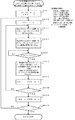
ここで、前述したステップS405における「光学検知部10による挿入紙幣1の受光データ収集の処理」の動作の詳細を図5乃至図8を参照しながら説明し、ステップS408における受光データ補正部45による「光学検知部10で収集された反射光データの色補正処理」の詳細を図9を参照しながら説明し、ステップS409におけるパールデータ判定部50による「色補正後の反射光データに基づく真偽判定処理」の詳細を図10乃至図11を参照しながら説明し、ステップS411における透かしデータ判定部60による「透かし領域の真偽判定処理」の詳細を図12を参照しながら説明する。
Here, the details of the operation of “the process of collecting the received light data of the inserted
図5は、マイクロコンピュータ95の制御部30の指令信号に基づき光学検知部10による受光データ収集処理の動作を示す概略フローチャートであり、図6乃至図8は、図5の概略フローチャートの各ステップにおける処理動作の詳細を示すフローチャートである。
FIG. 5 is a schematic flowchart showing the operation of the received light data collection processing by the
図5のフローチャートに示すように、光学検知部10による挿入紙幣1の各面の各計測位置での受光データ(反射光データ、透過光データ)の収集処理動作は、挿入紙幣1上面のパール光検出センサーと非パール光検出センサーによる2色(赤、緑)の各反射光データの収集(ステップS501)、挿入紙幣1下面のパール光検出センサーと非パール光検出センサーによる2色(赤、緑)の各反射光データの収集(ステップS502)、透かしセンサーによる2色(赤、緑)の各透過光データの収集(ステップS503)の順で挿入紙幣1の計測開始位置から計測終了位置まで順次行われ、挿入紙幣1が光学検知部10を通過することで(ステップS504でYES)、光学検知部10による挿入紙幣1の1枚分のデータ収集処理が終了する。
As shown in the flowchart of FIG. 5, the collection processing operation of the received light data (reflected light data, transmitted light data) at each measurement position on each surface of the inserted
ステップS501における「パール光検出センサーと非パール光検出センサーによる挿入紙幣1上面の反射光データの収集」の処理動作は、具体的には、上光源11の2色(赤、緑)のLEDを順次発光させ、受光素子13で受光される挿入紙幣1上面の各色の反射光量に対応した受光出力値のデータを収集し、次に上光源12の2色(赤、緑)のLEDを順次発光させ、受光素子13で受光される挿入紙幣1上面の各色の反射光量に対応した受光出力値のデータを収集する。
Specifically, the processing operation of “collection of reflected light data on the upper surface of the inserted
具体的には、図6のフローチャートに示すように、挿入紙幣1の各計測位置に対応してマイクロコンピュータ95の制御部30が上光源11の赤色LEDのトランジスタをON(ステップS601、602、603)、赤色LEDのD/Aコンバータ18R(図2参照)へ電流設定値を出力して上光源11の赤色LEDを発光させ(ステップS604)、受光素子13の受光出力が安定したところで(ステップS605でYES)、搬送紙幣1上面の反射光に対応して受光素子13から出力される受光出力信号をアンプ回路19で増幅し、A/Dコンバータ20でデジタルの反射光データに変換し、マイクロコンピュータ95のメモリ70の所定の記憶領域に記憶する。
Specifically, as shown in the flowchart of FIG. 6, the control unit 30 of the
このパール光検出センサーによる挿入紙幣1上面の赤色反射光データが記憶されるメモリ70の所定の記憶領域は、具体的には、NAMDAT(SIDE、LED、COL、ADR)に対応付けられた記憶領域であり、NAMDAT(SIDE、LED、COL、ADR)の各変数は、SIDEが上光源を示す「0」と下光源を示す「1」の値、LEDが上光源11を示す「0」と上光源12を示す「1」の値、COLが赤色LEDを示す「0」と緑色LEDを示す「1」の値、ADRが挿入紙幣1のデータ収集位置の情報を示す値でそれぞれ対応付けられて管理されており、上光源11の赤色LED発光による挿入紙幣1上面の反射光データは、SIDE=0、LED=0、COL=0、ADR=n(nは、計測開始位置の0値〜計測終了位置のn値の計測位置に対応する値)の記憶領域に記憶される。
The predetermined storage area of the
上光源11の赤色LED発光による紙幣1上面の計測位置での反射光データの収集が終わると、上光源11の赤色LEDのトランジスタをOFF、赤色LEDのD/Aコンバータ18Rの電流設定値を0にし(ステップS606)、次に上光源11の緑色LEDを発光させ、前述と同様に挿入紙幣1上面の反射光に対応して受光素子13から出力される受光出力信号をアンプ回路19、A/Dコンバータ20を介してメモリ70のNAMDAT(SIDE、LED、COL、ADR)、各変数の値がSIDE=0、LED=0、COL=1、ADR=n(nは、計測開始位置の0値〜計測終了位置のn値の計測位置に対応する値)の記憶領域に記憶する。
When the collection of the reflected light data at the measurement position on the upper surface of the
なお、上光源11の緑色LEDを発光させる場合は、緑色LEDのトランジスタをON(ステップS603)、緑色LEDのD/Aコンバータ18G(図2参照)へ電流設定値を出力し(ステップS604)、受光素子13の受光出力が安定したところで(ステップS605でYES)、搬送紙幣1上面で反射する反射光を受光素子13で受光する。
When the green LED of the upper
上光源11の2色発光による紙幣1上面の反射光データの収集が終了すると(ステップS608でYES)、次に上光源12の赤色LED、緑色LEDの順で発光させ、前述の上光源11の2色発光による紙幣1上面の反射光データ収集の処理動作と同様に、上光源12の赤色LED発光による紙幣1上面の反射光データをメモリ70のNAMDAT(SIDE、LED、COL、ADR)、各変数値がSIDE=0、LED=1、COL=0、ADR=n(nは、計測開始位置の0値〜計測終了位置のn値の計測位置に対応する値)の記憶領域に順次記憶し、挿入紙幣1の1枚分データが各記憶領域に記憶される。
When the collection of the reflected light data on the upper surface of the
次に上光源12の緑色LED発光による紙幣1上面の反射光データをメモリ70のNAMDAT(SIDE、LED、COL、ADR)、各変数値がSIDE=0、LED=1、COL=1、ADR=n(nは、計測開始位置の0値〜計測終了位置のn値の計測位置に対応する値)の記憶領域に順次記憶し、挿入紙幣1の1枚分データが各記憶領域に記憶される。
Next, the reflected light data of the upper surface of the
挿入紙幣1の計測位置での紙幣1上面の反射光データが記憶されると、上光源12の緑色LEDのトランジスタをOFF、緑色LEDのD/Aコンバータ18Gの電流設定値を0に設定し(ステップS606)、次に図5で示したステップS502における「パール光検出センサーと非パール光検出センサーによる挿入紙幣1下面の2色(赤、緑)の各反射光データの収集」の処理を行う。
When the reflected light data on the upper surface of the
具体的には、下光源14の2色(赤、緑)のLEDを順次発光させ、受光素子16で受光される挿入紙幣1下面の各計測位置での各色の反射光データと受光素子15で受光される挿入紙幣1下面の各計測位置での各色の反射光データとを所定の記憶領域に順次記憶し、挿入紙幣1の1枚分の各計測位置での反射光データを収集する。
Specifically, the two-color (red and green) LEDs of the lower
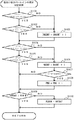
挿入紙幣1下面のパール光検出センサーと非パール光検出センサーによる各色の反射光データの収集処理は、図7のフローチャートに示すように、下光源14の赤色LEDのトランジスタをON(ステップS701、702、703)、赤色LEDのD/Aコンバータ18R(図2参照)へ電流設定値を出力し、下光源14の赤色LEDを発光させ(ステップS704)、受光素子16の受光出力が安定したところで(ステップS705でYES)、紙幣1下面の反射光に対応して受光素子16から出力される受光出力信号をアンプ回路23で増幅し、A/Dコンバータ24でデジタルの反射光データに変換し、メモリ70のNAMDAT(SIDE、PTX、COL、ADR)の記憶領域へ記憶する。
As shown in the flowchart of FIG. 7, the collection processing of the reflected light data of each color by the pearl light detection sensor and the non-pearl light detection sensor on the lower surface of the inserted
なお、NAMDAT(SIDE、PTX、COL、ADR)の変数PTXは、受光素子16の指定を示す「0」と受光素子15の指定を示す「1」の各値が設定され、このパール光検出センサーによる挿入紙幣1下面の赤色反射光データは、SIDE=1、PTX=0、COL=0、ADR=n(nは、計測開始位置の0値〜計測終了位置のn値の計測位置に対応する値)のNAMDAT(SIDE、PTX、COL、ADR)の記憶領域に記憶される。
The variable PTX of NAMDAT (SIDE, PTX, COL, ADR) is set to “0” indicating the designation of the
下光源14の赤色LED発光による紙幣1下面の反射光データの収集が終わると、赤色LEDのトランジスタをOFF、D/Aコンバータ18Rの電流設定値を0に設定後(ステップS706)、下光源14の緑色LEDを発光させ、前述と同様に挿入紙幣1下面の反射光に対応して受光素子16から出力される受光出力信号をアンプ回路23、A/Dコンバータ24を介してメモリ70のNAMDAT(SIDE、PTX、COL、ADR)、各変数の値がSIDE=1、PTX=0、COL=1、ADR=n(nは、計測開始位置の0値〜計測終了位置のn値の計測位置に対応する値)の記憶領域に記憶する。
なお、下光源11の緑色LEDの発光は、緑色LEDのトランジスタをON(ステップS703)、D/Aコンバータ18G(図2参照)へ電流設定値を出力し(ステップS704)、受光素子16の受光出力が安定後(ステップS705でYES)、紙幣1下面での反射光を受光素子16で受光する。
When the collection of reflected light data on the lower surface of the
Note that the green LED of the lower
下光源14の2色発光及び受光素子16による紙幣1下面の反射光データの収集、すなわちパール光検出センサーによる挿入紙幣1下面の2色(赤、緑)の各反射光データの収集が終了すると(ステップS708でYES)、次に非パール光検出センサーによる挿入紙幣1下面の2色(赤、緑)の各反射光データの収集を行う。
When the collection of the reflected light data of the lower surface of the
具体的には、前述の下光源14の2色発光及び受光素子16による紙幣1下面の反射光データ収集の処理動作と同様に、下光源14の2色(赤、緑)LEDを順次発光させ、紙幣1下面で反射する反射光を受光素子15で受光し、受光素子15から出力される受光出力信号をアンプ回路23、A/Dコンバータ24を介してメモリ70のNAMDAT(SIDE、PTX、COL、ADR)に記憶する。
Specifically, the two-color (red, green) LEDs of the lower
なお、下光源14の赤色LED発光及び受光素子15による紙幣1下面の反射光データは、SIDE=1、PTX=1、COL=0、ADR=n(nは、計測開始位置の0値〜計測終了位置のn値の計測位置に対応する値)のNAMDAT(SIDE、PTX、COL、ADR)の記憶領域へ、緑色LED発光及び受光素子15による紙幣1下面の反射光データは、SIDE=1、PTX=1、COL=1、ADR=n(nは、計測開始位置の0値〜計測終了位置のn値の計測位置に対応する値)のNAMDAT(SIDE、PTX、COL、ADR)の記憶領域へそれぞれ記憶され、下光源14の緑色LEDのトランジスタをOFF、D/Aコンバータ18Gの電流設定値を0に設定し(ステップS706)、次に図5で示したステップS503の透かしセンサーによる挿入紙幣1を透過する各色の透過光を受光素子15で受光して透過光データを収集する。
The reflected light data of the lower surface of the
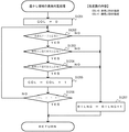
具体的には、図8のフローチャートに示すように、上光源12の2色(色、緑)のLEDを順次発光させ、挿入紙幣1を透過する透過光を受光素子15で受光し、挿入紙幣1の各計測位置での各色の透過光データを挿入紙幣1の1枚分について収集する。
Specifically, as shown in the flowchart of FIG. 8, the two color (color, green) LEDs of the upper
先ず、赤色LEDのトランジスタをON、D/Aコンバータ18Rへの電流値を設定して上光源12の赤色LEDを発光させ(ステップS801、802、803)、受光素子15の受光出力が安定後(ステップS804でYES)、搬送紙幣1の透過光が受光素子15で検出されて出力される受光出力信号をアンプ回路21、A/Dコンバータ22を介してメモリ70のNAMDAT2(COL、ADR)に対応付けられたメモリ70の記憶領域に記憶する(ステップS805乃至806)。
First, the transistor of the red LED is turned on, the current value to the D / A converter 18R is set, and the red LED of the upper
なお、NAMDAT2(COL、ADR)の各変数は、COLが赤色LEDを示す「0」と緑色LEDを示す「1」の値、ADRが挿入紙幣1のデータ収集位置の情報を示す値でそれぞれ対応付けられて管理されており、上光源12の赤色LED発光及び受光素子15による挿入紙幣1の透過光データをCOL=0、ADR=n(nは、計測開始位置の0値〜計測終了位置のn値の計測位置に対応する値)のNAMDAT2(COL、ADR)の記憶領域へ記憶する。
Note that each variable of NAMDAT2 (COL, ADR) corresponds to a value of “0” indicating that the COL is a red LED and a value of “1” indicating a green LED, and a value indicating the data collection position information of the inserted
上光源12の赤色LED発光による紙幣1の計測位置での透過光データの収集を終えると(ステップS807でNO)、上光源12の緑色LEDを発光させ、前述と同様に紙幣1を透過する透過光を受光素子15で受光し、透過光データをCOL=1、ADR=n(nは、計測開始位置の0値〜計測終了位置のn値の計測位置に対応する値)のNAMDAT2(COL、ADR)の記憶領域へ記憶するとともに緑色LEDのトランジスタをOFF、D/Aコンバータ18Gの電流設定値を0にし(ステップS805)、上光源12の2色発光及び受光素子15による搬送紙幣1の透過光データ収集の処理動作は終了する(ステップS806乃至ステップS807でYES)。
When the collection of transmitted light data at the measurement position of the
このようにパール光検出センサーと非パール光検出センサーによる挿入紙幣1の各面の各計測位置での反射光データの収集、透かしセンサーによる挿入紙幣1の透過光データの収集が挿入紙幣1が光学検知部10を通過するまで繰り返し行われることで、挿入紙幣1の1枚分の反射光データと透過光データとの受光データが収集される。
In this way, the collection of reflected light data at each measurement position on each surface of the inserted
前述に示した図4のメインフローチャートに示すように、紙葉類識別装置100が、挿入された紙幣1の各計測位置での磁気センサー/透過光識別センサー等89や光学検知部10による磁気データと反射光データや透過光データの受光データが検出され、挿入紙幣1の1枚分の各受光データがメモリ70の所定の記憶領域に記憶されると(ステップS406でYES)、マイクロコンピュータ95の金種及び挿入方向判定部40が磁気センサー/透過光識別センサー等89で検出された磁気データと受光データに基づき挿入紙幣1の金種と挿入方向(表裏、正逆)を判定する(ステップS407でYES)。
As shown in the main flow chart of FIG. 4 described above, the paper sheet identification device 100 uses the magnetic sensor / transmitted
金種及び挿入方向判定部40で挿入紙幣1の金種と挿入方向が判定されると、判定された挿入紙幣1の金種と挿入方向に基づき透かし領域データ特定部46が透かし領域データアドレス参照表を参照して挿入紙幣1の透かし領域の受光データが格納されたメモリ70の記憶領域を特定し、挿入紙幣1の透かし領域の反射光データをメモリ70から読み出す。
そして受光データ補正部45が透かし領域データ特定部46により読み出された挿入紙幣1の透かし領域の反射光データに基づき透かし領域における赤色反射光データと緑色反射光データの各受光出力値が予め定められた規定値となるように挿入紙幣1の全ての反射光データに対して補正を行う。
When the denomination and insertion
The received light output values of the red reflected light data and the green reflected light data in the watermark area are determined in advance based on the reflected light data of the watermark area of the inserted
具体的には、挿入紙幣1の金種と挿入方向に応じて光学検知部10の各パール光検出センサーにより検出されメモリ70に格納される挿入紙幣1の透かし領域の各反射光データのうちの赤色反射光の受光出力値と緑色反射光の受光出力値との和が最大(最大受光出力)となる計測位置での各色の受光出力値(最大受光出力値)が補正基準値である255の値となるように挿入紙幣1から収集した全ての反射光データの受光出力値を補正する(ステップS408)。
Specifically, of the reflected light data of the watermark area of the inserted
なお、赤色反射光データの受光出力値を「受光出力値(赤色)」といい、緑色反射光データの受光出力値を「受光出力値(緑色)」という。 The light reception output value of the red reflected light data is referred to as “light reception output value (red)”, and the light reception output value of the green reflected light data is referred to as “light reception output value (green)”.
この色補正による挿入紙幣1の各計測位置での補正値は、次式1及び式2で算出する。
The correction value at each measurement position of the inserted
赤色反射光データを色補正する場合は、次式1で算出する。
When color correction is performed on the reflected red light data, the following
挿入紙幣1の各計測位置での補正値(赤色)=各計測位置での反射光データの受光出力値(赤色)/最大受光出力値(赤色)×255。
Correction value (red) at each measurement position of the inserted
また、緑色反射光データを色補正する場合は、次式2で算出する。
Further, when the color of the green reflected light data is corrected, it is calculated by the
挿入紙幣1の各計測位置での補正値(緑色)=各計測位置での反射光データの受光出力値(緑色)/最大受光出力値(緑色)×255。
Correction value (green) at each measurement position of the inserted
なお、「255」の値は、補正基準値を「255」として設定した値であり、「100」でもよく、特に限定されるものではない。 The value “255” is a value set with the correction reference value “255”, and may be “100”, and is not particularly limited.
この色補正の処理動作の詳細は、図9のフローチャートに示すように、まず、透かし領域データ特定部46によりメモリ70のNAMDAT(SIDE、LED、COL、ADR)から読み出された挿入紙幣1の透かし領域の反射光データに基づき受光データ補正部45が各パール光検出センサーで検出された透かし領域内の各計測位置での赤色反射光データの受光出力値と緑色反射光データの受光出力値との和が最大(最大受光出力)となる計測位置をそれぞれ求め、それら計測位置での受光データが格納されたメモリ70のアドレスを最大受光出力に対応した各色の反射光データを読み出すポインターとしてメモリ70のMAXADR(SIDE、LED)の記憶領域に記憶する(ステップS901)。
As shown in the flowchart of FIG. 9, the details of the color correction processing operation are as follows. First, the
なお、MAXADR(SIDE、LED)の変数SIDEは、上光源の指定を示す「0」または下光源の指定を示す「1」の各値が設定され、変数LEDは、上光源11の指定(SIDE=0の時)もしくは受光素子16の指定(SIDE=1の時)を示す「0」、または上光源12の指定(SIDE=0の時)もしくは受光素子15の指定(SIDE=1の時)を示す「1」の各値が設定されるようにそれぞれ対応付けられている。
The variable SIDE of MAXADR (SIDE, LED) is set to each value of “0” indicating the designation of the upper light source or “1” indicating the designation of the lower light source, and the variable LED is designated (SIDE) of the upper
具体的には、挿入紙幣1の透かし領域内の各計測位置での上光源11と受光素子13から成るパール光検出センサーで検出された赤色反射光データの受光出力値(赤色)と緑色反射光データの受光出力値(緑色)との和を順次算出し、赤色反射光データの受光出力値(赤色)と緑色反射光データの受光出力値(緑色)との和が最大(最大受光出力)となる各色の反射光データの受光出力値と、各色の反射光データがメモリ70に格納されているアドレスを特定して、特定したアドレスを最大受光出力に対応した受光データの位置情報としてMAXADR(SIDE、LED)、SIDE=0、LED=0に格納する。
Specifically, the received light output value (red) of the red reflected light data detected by the pearl light detection sensor including the upper
また、上光源12と受光素子13から成る非パール光検出センサーで検出された赤色反射光データの受光出力値(赤色)と緑色反射光データの受光出力値(緑色)との和が最大となる位置情報を前述と同様な方法で算出し、そのアドレスをMAXADR(SIDE、LED)、SIDE=0、LED=1に格納する。
Further, the sum of the received light output value (red) of the red reflected light data and the received light output value (green) of the green reflected light data detected by the non-pearl light detection sensor including the upper
また、下光源14と受光素子16から成るパール光検出センサー及び下光源14と受光素子15から成る非パール光検出センサーでそれぞれ検出された赤色反射光データの受光出力値(赤色)と緑色反射光データの受光出力値(緑色)との和が最大(最大受光出力)となるアドレスを前述と同様な方法で特定し、下光源14と受光素子16から成るパール光検出センサーによる最大受光出力の各色の反射光データのアドレスをMAXADR(SIDE、LED)、SIDE=1、LED=0に格納し、下光源14と受光素子15から成る非パール光検出センサーによる最大受光出力の各色の反射光データのアドレスをMAXADR(SIDE、LED)、SIDE=1、LED=1にそれぞれ格納する。
Further, the received light output value (red) and the green reflected light of the red reflected light data detected by the pearl light detecting sensor comprising the lower
挿入紙幣1の透かし領域における各パール光検出センサーで検出された赤色反射光データの受光出力値(赤色)と緑色反射光データの受光出力値(緑色)との和が最大となる位置情報がメモリ70のMAXADR(SIDE、LED)にそれぞれ格納されると、次に挿入紙幣1の各面の各計測位置で収集された赤色及び緑色の各反射光データの受光出力値の色補正を赤色反射光データについては上式1により、緑色反射光データについては上式2により算出し、算出結果をメモリ70のPALDATに対応付けられた記憶領域に格納する。
具体的には、次式3で算出する。
The position information in which the sum of the received light output value (red) of the red reflected light data (red) and the received light output value (green) of the green reflected light data detected by each pearl light detection sensor in the watermark area of the inserted
Specifically, it is calculated by the
PALDAT(SIDE、LED、COL、ADR)=NAMDAT(SIDE、LED、COL、ADR)×255/NAMDAT(SIDE、LED、COL、MAXADR(SIDE、LED))。 PALDAT (SIDE, LED, COL, ADR) = NAMDAT (SIDE, LED, COL, ADR) × 255 / NAMDAT (SIDE, LED, COL, MAXADR (SIDE, LED)).
上式3において、挿入紙幣1上面の計測開始位置における上光源11と受光素子13から成るパール光検出センサーで検出された赤色反射光データの受光出力値(赤色)の補正値をSIDE=0、LED=0、COL=0、ADR=0、MAXADR(SIDE、LED)で算出し、緑色反射光データの受光出力値(緑色)の補正値をSIDE=0、LED=0、COL=1、ADR=0、MAXADR(SIDE、LED)で算出して各記憶領域PALDAT(SIDE、LED、COL、ADR)に記憶する(ステップS902乃至ステップS908でYES)。
In the
また、上式3において、挿入紙幣1上面の計測開始位置における上光源12と受光素子13から成る非パール光検出センサーで検出された赤色反射光の受光出力値(赤色)の補正値をSIDE=0、LED=1、COL=0、ADR=0、MAXADR(SIDE、LED)で算出し、緑色反射光データの受光出力値(緑色)の補正値をSIDE=0、LED=1、COL=1、ADR=0、MAXADR(SIDE、LED)で算出して各記憶領域PALDAT(SIDE、LED、COL、ADR)に記憶し(ステップS909、ステップS910でNO)、前述で示したステップS905乃至ステップS910と同様な処理を挿入紙幣1上面の計測開始終了位置(ADR=0、1、2、・・・、n)になるまで繰り返すことで挿入紙幣1上面の各パール光検出センサーで検出された赤色及び緑色反射光データの受光出力値の補正値が算出され、算出された各補正値が所定の記憶領域PALDAT(SIDE、LED、COL、ADR)に記憶される(ステップS904乃至ステップS912でYES)。
Further, in the
挿入紙幣1上面の各パール光検出センサーで検出された赤色及び緑色反射光データの受光出力値の補正値を算出し、算出した各補正値を所定の記憶領域PALDAT(SIDE、LED、COL、ADR)に記憶すると、挿入紙幣1下面の各パール光検出センサーで検出された赤色及び緑色反射光データの受光出力値についても前述と同様な色補正処理を行う。
The correction value of the light reception output value of the red and green reflected light data detected by each pearl light detection sensor on the upper surface of the inserted
具体的には、上式3において、挿入紙幣1下面の計測開始位置における下光源14と受光素子16から成るパール光検出センサーで検出された赤色反射光データの受光出力値(赤色)の補正値をSIDE=1、LED=PTX=0、COL=0、ADR=0、MAXADR(SIDE、LED)で算出し、緑色反射光データの受光出力値(緑色)の補正値をSIDE=1、LED=PTX=0、COL=1、ADR=0、MAXADR(SIDE、LED)で算出して各記憶領域PALDAT(SIDE、LED、COL、ADR)に記憶する(ステップS913、ステップS914でNO、ステップS903乃至ステップS908)。
Specifically, in the
また、上式3において、挿入紙幣1下面の計測開始位置における下光源14と受光素子15から成る非パール光検出センサーで検出された赤色反射光の受光出力値(赤色)の補正値をSIDE=1、LED=PTX=1、COL=0、ADR=0、MAXADR(SIDE、LED)で算出し、緑色反射光データの受光出力値(緑色)の補正値をSIDE=1、LED=PTX=1、COL=1、ADR=0、MAXADR(SIDE、LED)で算出して各記憶領域PALDAT(SIDE、LED、COL、ADR)に記憶し(ステップS909、ステップS910でNO、ステップS905乃至ステップS910)、前述で示したステップS905乃至ステップS910と同様な処理を挿入紙幣1下面の計測開始終了位置(ADR=0、1、2・・・、n)になるまで繰り返すことで挿入紙幣1下面の各パール光検出センサーで検出された赤色及び緑色反射光データの受光出力値の補正値が算出され、算出された各補正値が所定の記憶領域PALDAT(SIDE、LED、COL、ADR)に記憶される(ステップS904乃至ステップS912、ステップS912でYES)。
Further, in the
このように、受光データ補正部45による光学検知部10で収集された挿入紙幣1の各面の各色の反射光データの色補正処理が終了すると、色補正処理された各色の反射光データ(以下、「色補正データ」という。)に基づき挿入紙幣1が偽券であるか否かの判定処理を行う(図4のステップS409参照)。
Thus, when the color correction processing of the reflected light data of each color of each surface of the inserted
この判定処理は、パールデータ判定部50が挿入紙幣1の各面の各計測位置での色補正データから求めたインキの色合いやパールインキ成分と、その判定基準とに基づき挿入紙幣1が偽券であるか否かの判定処理を行う。
In this determination process, the inserted
具体的には、図10のフローチャートに示すように、真偽識別フラグBILNGや各カウンタNGCNT、PNG、パールインキ成分の最小値PLMIN、挿入紙幣1上下面を指定するSIDE等の各値を記憶する各記憶領域を初期化した後(ステップS1001)、パール光検出センサーにより収集された挿入紙幣1の各面の各計測位置での反射光データの赤色補正データと緑色補正データとの比率(赤緑比率(斜光))COLDAT0と、非パール光検出センサーにより収集された挿入紙幣1の各面の各計測位置での反射光データの赤色補正データと緑色補正データとの比率(赤緑比率(垂直光))COLDAT1と、赤緑比率(斜光)と赤緑比率(垂直光)との比率(赤緑比率比)OUTDATとをそれぞれ算出し(ステップS1002、ステップS1003、ステップS1004、ステップS1005)、各算出値と真正紙幣から予め取得したそれぞれの許容値(上限値、下限値)との比較結果を「色合い及びパールインキ成分判定処理」で算出し、比較結果に基づき紙幣1が偽券であるか否かの判定処理を行う。
Specifically, as shown in the flowchart of FIG. 10, the authenticity identification flag BILNG, each counter NGCNT, PNG, the minimum value PLMIN of the pearl ink component, SIDE that specifies the upper and lower surfaces of the inserted
なお、「色合い及びパールインキ成分判定処理」の詳細については後述する。 Details of the “color and pearl ink component determination process” will be described later.
算出された赤緑比率(垂直光)COLDAT1からは、挿入紙幣1に印刷されたインキの色合いを含む情報を、赤緑比率比OUTDATからは、挿入紙幣1に印刷されたパールインキ成分の情報を得ることができることから、予め多くの真正紙幣から収集した真正紙幣上の各面各計測位置での色合い(赤緑比率(垂直光)COLDAT1)値やパールインキ成分(赤緑比率比OUTDAT)値に基づき、各値のばらつき考慮して真正紙幣の赤緑比率(垂直光)COLDAT1値の下限値CLOWLMT(KIN、INS、ADR)と上限値CHILMT(KIN、INS、ADR)、赤緑比率比OUTDAT値の下限値LOWLMT(KIN、INS、ADR)と上限値HILMT(KIN、INS、ADR)を設定し、挿入紙幣1上の各計測位置での赤緑比率(垂直光)COLDAT1値(色合い)や赤緑比率比OUTDAT値が真正紙幣の赤緑比率(垂直光)COLDAT1値(色合い)や赤緑比率比OUTDAT値の各下限値や上限値を超えた回数をカウントすることで挿入紙幣1に形成されたインキの色合いやパールインキ成分と、判定基準とに基づく真偽の識別が可能となる。
From the calculated red / green ratio (vertical light) COLDAT1, information including the color of the ink printed on the inserted
なお、パールインキが印刷されていない領域(例えば無地領域や着色印刷領域等)では、赤緑比率比OUTDAT値が大きな値(例えば255近傍)を示し、パールインキが印刷されている領域では、小さな値を示す。 It should be noted that the red / green ratio ratio OUTDAT value is large (for example, near 255) in a region where the pearl ink is not printed (for example, a plain region or a colored printing region), and is small in a region where the pearl ink is printed. Indicates the value.
赤緑比率(斜光)COLDAT0は、次式4で算出する。
The red-green ratio (oblique light) COLDAT0 is calculated by the
COLDAT0=PALDAT(SIDE、0、1、ADR)/PALDAT(SIDE、0、0、ADR)×255。 COLDAT0 = PALDAT (SIDE, 0, 1, ADR) / PALDAT (SIDE, 0, 0, ADR) × 255.
上式4において、上光源11の発光と受光素子13の受光(パール光検出センサー)による挿入紙幣1上面の各計測位置での反射光データの赤色補正データと緑色補正データとの赤緑比率(斜光)は、SIDE=0、ADR=n(nは、計測開始位置の0値〜計測終了位置のn値の計測位置に対応する値)で示され、下光源14の発光と受光素子16(パール光検出センサー)による挿入紙幣1下面の各計測位置での反射光データの赤色補正データと緑色補正データとの赤緑比率(斜光)は、SIDE=1、ADR=n(nは、計測開始位置の0値〜計測終了位置のn値の計測位置に対応する値)で示される。
In the
また、赤緑比率(垂直光)COLDAT1は、次式5で算出する。
Further, the red-green ratio (vertical light) COLDAT1 is calculated by the
COLDAT1=PALDAT(SIDE、1、1、ADR)/PALDAT(SIDE、1、0、ADR)×255。 COLDAT1 = PARDAT (SIDE, 1, 1, ADR) / PALDAT (SIDE, 1, 0, ADR) × 255.
上式5において、上光源12の発光と受光素子13の受光(非パール光検出センサー)による挿入紙幣1上面の各計測位置での反射光データの赤色補正データと緑色補正データとの赤緑比率(垂直光)は、SIDE=0、ADR=n(nは、計測開始位置の0値〜計測終了位置のn値の計測位置に対応する値)で示され、下光源14の発光と受光素子15(非パール光検出センサー)による挿入紙幣1下面の各計測位置での反射光データの赤色補正データと緑色補正データとの赤緑比率(垂直光)は、SIDE=1、ADR=n(nは、計測開始位置の0値〜計測終了位置のn値の計測位置に対応する値)で示される。
In the
また、赤緑比率(斜光)COLDAT0と赤緑比率(垂直光)COLDAT1との赤緑比率比OUTDATは、次式6で算出する。 Further, the red-green ratio ratio OUTDAT between the red-green ratio (oblique light) COLDAT0 and the red-green ratio (vertical light) COLDAT1 is calculated by the following equation (6).
OUTDAT=COLDAT0/COLDAT1×255。 OUTDAT = COLDAT0 / COLDAT1 × 255.
挿入紙幣1の各面の各計測位置での赤緑比率(垂直光)COLDAT1と赤緑比率比OUTDATとが算出されると、各算出値と真正紙幣から予め取得したそれぞれの許容値(上限値、下限値)との比較結果を「色合い及びパールインキ成分判定処理」で算出する(ステップS1006)。
When the red-green ratio (vertical light) COLDAT1 and the red-green ratio ratio OUTDAT at each measurement position on each surface of the inserted
この「色合い及びパールインキ成分判定処理」は、図11のフローチャートに示すように、非パール光検出センサーにより収集された挿入紙幣1の赤色反射光データの赤色補正データと緑色反射光データの緑色補正データとの赤緑比率(垂直光)COLDAT1値が真偽判定基準の下限値CLOWLMT(KIN、INS、ADR)や上限値CHILMT(KIN、INS、ADR)を超えた場合(ステップS1101でNO、ステップS1102でNO)、すなわち挿入紙幣1の各面の各計測位置での色合いが真正紙幣から収集した色合いの許容範囲を超えた場合は、カウンタCNGCNTをカウントアップし(ステップS1103)、挿入紙幣1の各面の各計測位置での赤緑比率(斜光)COLDAT0と赤緑比率(垂直光)COLDAT1との赤緑比率比OUTDATが真偽判定基準の下限値LOWLMT(KIN、INS、ADR)や上限値HILMT(KIN、INS、ADR)を超えた場合(ステップS1104でNO、ステップS1105でNO)、すなわち挿入紙幣1の各面の各計測位置でのパールインキ成分を示す値が真正紙幣から収集したパールインキ成分を示す値の許容範囲を超えた場合は、カウンタNGCNTをカウントアップし(ステップS1106)、更に、その計測位置が挿入紙幣1のパールインキが印刷された領域内であれば(ステップS1107でYES)、カウンタPNGをカウントアップ後(ステップS1108)、挿入紙幣1の赤緑比率比OUTDATの最小値PLMINを検出し(ステップS1109、ステップS1110)、挿入紙幣1の1枚分の各カウンタ値CNGCNT、NGCNT、PNG及び赤緑比率比OUTDATの最小値PLMINを検出する。
As shown in the flowchart of FIG. 11, this “color and pearl ink component determination process” includes red correction data of red reflected light data and green correction of green reflected light data of the inserted
なお、各計測位置が挿入紙幣1のパールインキが印刷された領域内であるか否かの判別は、メモリ70に格納されたパールインキ印刷部データアドレス参照表を参照することで判別することができる。
Whether each measurement position is in the area where the pearl ink of the inserted
図10のフローチャートに示すように、挿入紙幣1の1枚分の各カウンタ値NGCNT、PNG及び赤緑比率比OUTDATの最小値PLMINが検出されると(ステップS1008でYES)、これらの値に基づき挿入紙幣1の真偽判定を行う。
As shown in the flowchart of FIG. 10, when each counter value NGCNT, PNG and the minimum value PLMIN of the red / green ratio ratio OUTDAT for one inserted
具体的には、挿入紙幣1のパールインキ成分値が許容範囲を超えたカウント値NGCNT、すなわち、挿入紙幣1全体のパール光データの欠損数が所定の真偽判定基準値TLMTを超えたか否かを判別し(ステップS1009)、超えた場合は(ステップS1009でNO)、真偽識別フラグBILNGを「1」と設定後(ステップS1013)、挿入紙幣1を偽券と判定し処理を終了する。
Specifically, the count value NGCNT in which the pearl ink component value of the inserted
また、カウント値NGCNTが所定の真偽判定基準値TLMTの範囲内であれば(ステップS1009でYES)、挿入紙幣1のパールインキが印刷された領域におけるパールインキ成分値が許容範囲を超えたカウント値PNG、すなわち、挿入紙幣1のパールインキ領域の欠損数が所定の真偽判定基準値PNGLMTを超えたか否かを判別し(ステップS1010)、超えた場合は(ステップS1010でNO)、真偽識別フラグBILNGを「1」と設定後(ステップS1013)、挿入紙幣1を偽券と判定し処理を終了する。
Further, if the count value NGCNT is within the range of the predetermined authenticity determination reference value TLMT (YES in step S1009), the pearl ink component value in the area where the pearl ink of the inserted
また、カウント値PNGが所定の真偽判定基準値PNGLMTの範囲内であれば(ステップS1010でYES)、挿入紙幣1の赤緑比率比OUTDATの最小値PLMINが所定の真偽判定基準値PLLMTより大きいか否かを判別し(ステップS1011)、小さい場合は(ステップS1011でNO)、真偽識別フラグBILNGを「1」と設定後(ステップS1013)、挿入紙幣1を偽券と判定し処理を終了する。
If the count value PNG is within the range of the predetermined authenticity determination reference value PNGLMT (YES in step S1010), the minimum value PLMIN of the red-green ratio ratio OUTDAT of the inserted
これまで述べたように、本発明の紙葉類識別装置は、光学検知部10の各光源や受光素子の経時劣化、または付着した埃による発光量や受光感度のばらつきによる識別判定のばらつきを抑えるために光学検知部10で収集した挿入紙幣1の全ての反射光データに対して色補正を行い、色補正データに基づく挿入紙幣1に印刷された各計測位置でのインキの色合いやパールインキ成分の算出値と基準値との比較によりパールインキの特性を精密に識別するので、挿入紙幣1に印刷されたパールインキが真券に印刷された特有のパールインキなのか、それ以外のインキなのかを高精度で判別することができる。
As described above, the paper sheet identification device of the present invention suppresses the variation in identification determination due to the temporal deterioration of each light source and light receiving element of the
色補正後の反射光データ(色補正データ)に基づき挿入紙幣1が偽券でないと判定されると(ステップS410でNO)、挿入紙幣1の透かし領域の反射光データ及び透過光データに基づき紙幣1が真券であるか否かの判定処理を行う(ステップS411)。
If it is determined that the inserted
ステップS411における「透かし領域の真偽判定処理」は、具体的には、挿入紙幣1の透かし領域の透過光データに基づき透かし模様に対応した透かしパターンが検知されているか否かの判別と、透かし領域の反射光データに基づき透かしパターンが検知されているか否かの判別結果に基づき真偽の判定を行う。
Specifically, the “watermark area authenticity determination processing” in step S411 specifically determines whether or not a watermark pattern corresponding to the watermark pattern is detected based on the transmitted light data of the watermark area of the inserted
例えば、透かし領域が形成された真正紙幣と透かし領域が形成されていない偽券とに光を照射して各透過光の受光出力を検出してみると、真正紙幣の場合は、透かしパターンが検知されるのに対し、偽券の場合は、透かしパターンが検知されないので透かしパターンが検知されたか否かに基づき真正紙幣と偽券との識別が容易にできる。 For example, when a genuine banknote with a watermark area and a counterfeit banknote without a watermark area are irradiated with light and the received light output of each transmitted light is detected, the watermark pattern is detected in the case of a genuine banknote. On the other hand, in the case of a counterfeit note, since a watermark pattern is not detected, it is possible to easily distinguish between a genuine bill and a counterfeit note based on whether or not a watermark pattern is detected.
しかし、透かし領域に表面複写もしくは、いたずら書きされた偽券の場合は、透かしパターンが検知されるので、透過光により透かしパターンが検知されたか否かに基づく真正紙幣と偽券との識別が困難となる。 However, in the case of a counterfeit note that is surface-copyed or doodled in the watermark area, the watermark pattern is detected, so it is difficult to distinguish between a genuine note and a counterfeit note based on whether the watermark pattern is detected by transmitted light. It becomes.
一方、透かし領域が形成された真正紙幣と透かし領域が形成されていない偽券とに光を照射して各反射光の受光出力を検出してみると、真正紙幣、偽券共に透かしパターンを検知することはできないが、透かし領域に表面複写もしくは、いたずら書きされた偽券の場合は、透かしパターンが検知されるので、透過光と反射光による透かしパターンが検知されたか否かを判別することで真正紙幣と偽券との識別が可能となる。 On the other hand, when a genuine bill with a watermark area and a counterfeit note with no watermark area are irradiated with light and the received light output of each reflected light is detected, both the genuine bill and the counterfeit are detected as a watermark pattern. However, in the case of a fake note that has been surface-copied or doodled in the watermark area, the watermark pattern is detected, so it is possible to determine whether the watermark pattern by transmitted light and reflected light has been detected. It is possible to distinguish between genuine bills and fake bills.
このようなことから、ステップS411における「透かし領域の真偽判定処理」の動作は、図12のフローチャートに示すように、透かしセンサーを構成する上光源12の赤色LEDの発光と受光素子15の受光により検出した挿入紙幣1の透かし領域の赤色透過光データに基づき透かしパターンが検知されない場合は(ステップS1201、ステップS1202でNO)、真偽識別フラグBILNGをカウントアップ後(ステップS1207)、挿入紙幣1を偽券と判定し、処理を終了する。
For this reason, the operation of the “watermark area authenticity determination process” in step S411 performs the light emission of the red LED of the upper
ステップS1202において、透かしパターンが検知された場合は(ステップS1202でYES)、上光源12の赤色LEDの発光及び受光素子13の受光により検出した挿入紙幣1上面の透かし領域の赤色反射光データに基づき透かしパターンが検知された場合は(ステップS1203でNO)、真偽識別フラグBILNGをカウントアップ後(ステップS1207)、挿入紙幣1を偽券と判定し、処理を終了する。
If a watermark pattern is detected in step S1202 (YES in step S1202), based on the red reflected light data of the watermark area on the upper surface of the inserted
ステップS1203において、透かしパターンが検知されない場合は(ステップS1203でYES)、下光源14の赤色LEDの発光及び受光素子15の受光により検出した挿入紙幣1下面の透かし領域の赤色反射光データに基づき透かしパターンが検知された場合は(ステップS1204でNO)、真偽識別フラグBILNGをカウントアップ後(ステップS1207)、挿入紙幣1を偽券と判定し、処理を終了する。
If the watermark pattern is not detected in step S1203 (YES in step S1203), the watermark is based on the red reflected light data of the watermark area on the bottom surface of the inserted
ステップS1204において、透かしパターンが検知されない場合は(ステップS1204でYES)、上光源12または下光源14の各緑色LEDを発光及び受光素子13または受光素子15の受光により検出した挿入紙幣1上面または下面の透かし領域の緑色透過光または反射光データに基づき前述のステップS1202乃至ステップS1204の判定動作を繰り返した後、透かし領域の真偽判定処理を終了する(ステップS1206でYES)。
If a watermark pattern is not detected in step S1204 (YES in step S1204), the upper or lower surface of the inserted
このように、挿入紙幣1の透かし領域の透過光データ、反射光データに基づく判定処理を組み合わせた処理を行うことで挿入紙幣1の真偽判定ができ、透過光データ、反射光データを2波長の発光により収集することで挿入紙幣1の真偽識別の精度がより向上する。
Thus, the authenticity determination of the inserted
図13は、これまで説明した紙葉類識別装置100とは他の本発明に係わる紙葉類識別装置200の構成例を示す構成図であり、図14は、紙葉類識別装置200の回路構成の一例を示す回路ブロック図である。 FIG. 13 is a block diagram showing a configuration example of a paper sheet identifying apparatus 200 according to the present invention, which is different from the paper sheet identifying apparatus 100 described so far, and FIG. 14 is a circuit diagram of the paper sheet identifying apparatus 200. It is a circuit block diagram which shows an example of a structure.
紙葉類識別装置200の構成例は、片面にのみパールインキが印刷された紙幣を表裏の挿入方向を特定して挿入させることで紙幣に印刷されたパールインキを精密に真偽識別するように構成したものである。 In the configuration example of the paper sheet identification device 200, the pearl ink printed on the banknote is accurately and genuinely identified by inserting the banknote printed with the pearl ink only on one side by specifying the front and back insertion directions. It is composed.
図13及び図14に示すように、紙葉類識別装置200は、挿入紙幣1上面に対して斜め方向及び垂直方向から2色(赤、緑)の光を照射する上光源11(第1の光源)、12(第2の光源)及び挿入紙幣1上面の反射光を受光する受光素子13(第1の受光素子)とを配置した光学検知部210を有するように構成されたものである。
As shown in FIG. 13 and FIG. 14, the paper sheet identification device 200 irradiates light of two colors (red and green) from the oblique direction and the vertical direction with respect to the upper surface of the inserted banknote 1 (first light source 11). The
なお、図13及び14に示す紙葉類識別装置200において、図1及び図2に示した紙葉類識別装置100と同様な構成及び動作する各部については、説明の便宜上、同一の符号を付して前述の説明を参照するものとし、構成及び動作の説明は、省略する。 In the paper sheet identification apparatus 200 shown in FIGS. 13 and 14, the same components and components that operate as those in the paper sheet identification apparatus 100 shown in FIGS. 1 and 2 are denoted by the same reference numerals for convenience of explanation. Therefore, the above description will be referred to, and description of the configuration and operation will be omitted.
図13及び図14に示すように、光学検知部210を備えた紙葉類識別装置200の構成としても、挿入紙幣1上面のパールインキに依存する、またはパールインキに依存しない色合いやパールインキが印刷された領域のパールインキ成分や色合いに基づき挿入紙幣1の真偽の判別を行うことで、挿入紙幣1の真偽識別の精度をより向上させることができる。
As shown in FIG. 13 and FIG. 14, even with the configuration of the paper sheet identification device 200 provided with the
具体的には、図15に示す紙葉類識別装置200の真偽識別処理動作の概略フローチャートに示すように、所定の挿入方向(表裏)で紙幣1が挿入されると、紙幣挿入検出センサー87が紙幣1が挿入されたことを検知し(ステップS1501でYES)、搬送モータ84が起動されて挿入紙幣1を搬送し、メモリー70の所定の記憶領域を初期化後(ステップS1502)、磁気センサー/透過光識別センサー等89、光学検知部10等の各センサーが起動する(ステップS1503でYES)。
Specifically, as shown in the schematic flowchart of the authenticity identification processing operation of the paper sheet identification device 200 shown in FIG. 15, when the
挿入紙幣1上面の各計測位置での磁気データや透かし領域のデータを磁気センサー/透過光識別センサー等89で検出し、2色(赤、緑)の反射光データを光学検知部10等の各センサーで検出して挿入紙幣1の1枚分の各データをメモリー70の所定の記憶領域に順次記憶する(ステップS1504、ステップS1505)。
Magnetic data and watermark area data at each measurement position on the upper surface of the inserted
なお、ステップS1505における「光学検知部210によるデータ収集」の処理動作は、前述の図6で示した「パール光検出センサー、非パール光検出センサーによる挿入紙幣1上面の反射光データ収集」の処理動作と同様であり、詳細説明は省略する。
Note that the processing operation of “data collection by the
各センサーによる挿入紙幣1の1枚分の各データ収集後(ステップS1506でYES)、金種及び挿入方向判定部40により判定された挿入紙幣1の金種と挿入方向に応じた挿入紙幣1上面の透かし領域の特定の反射光データに基づき色補正を行い(ステップS1508)、色補正処理された各色補正データに基づき挿入紙幣1の真偽判定処理を行い(ステップS1509)、判定結果に基づき真券(ステップS1510でYES)または偽券の判定を行う(ステップS1510でNO)。
After each data collection for one inserted
なお、ステップS1508における「光学検知部210で収集された反射光データの色補正処理」は、前述の図9で示した「光学検知部10で収集した反射光データの色補正処理」におけるSIDE=0の場合の処理動作と同様であり、ステップS1509における「色補正後の反射光データに基づく真偽判定処理」は、前述の図10、11で示した「色補正後の反射光データに基づく真偽判定処理」におけるSIDE=0の場合の処理動作及び「色合い及びパールインキ成分判定処理」の処理動作と同様であるので詳細説明は省略する。
Note that “color correction processing of reflected light data collected by
このように、紙葉類識別装置200では、挿入紙幣1の透かし領域の透過光に基づく真偽判定の処理は行わないが、挿入紙幣1上面の2色の反射光に基づく色合い識別、パールインキ成分の識別及びパールインキ領域の識別を行うので挿入紙幣1の識別精度がより向上する。
As described above, the paper sheet identification apparatus 200 does not perform the authenticity determination process based on the transmitted light of the watermark area of the inserted
1 挿入紙幣
2 真正紙幣
3、4 パールインキ
5 透かし領域
6 紙幣搬送路
10、210 光学検知部
11、12 上光源
13、15、16 受光素子
14 下光源
17、19、21、86、88、91 アンプ(回路)
17R アンプ(回路)(赤色LED用)
17G アンプ(回路)(緑色LED用)
18 D/Aコンバータ
18R D/Aコンバータ(赤色LED用)
18G D/Aコンバータ(緑色LED用)
20、22、24 A/Dコンバータ
30、31 制御部
40 金種及び挿入方向判定部
45 受光データ補正部
46 透かし領域データ特定部
50、51 パールデータ判定部
60 透かしデータ判定部
70 メモリ
80 紙幣搬送機構
81 搬送ベルト
82、83 ローラ
84 搬送モータ
85 エンコーダ
87 紙幣挿入検出センサー
89 磁気センサー/透過光識別センサー等
90 バス
95、96 マイクロコンピュータ
100、200 紙葉類識別装置
101 パール光検出センサーによる赤色反射光の受光出力信号波形
102 パール光検出センサーによる緑色反射光の受光出力信号波形
103 パール光検出センサーによる赤緑比率(斜光)の信号波形
104 非パール光検出センサーによる赤色反射光の受光出力信号波形
105 非パール光検出センサーによる緑色反射光の受光出力信号波形
106 非パール光検出センサーによる赤緑比率(垂直光)の信号波形
107 赤緑比率比の信号波形
DESCRIPTION OF
17R amplifier (circuit) (for red LED)
17G amplifier (circuit) (for green LED)
18 D / A converter 18R D / A converter (for red LED)
18G D / A converter (for green LED)
20, 22, 24 A /
Claims (9)
前記紙葉類の一面に対して所定の角度で複数の色の光を切り替え照射する第1の光源と、
前記紙葉類の一面に対して垂直方向から複数の色の光を切り替え照射する第2の光源と、
前記第1の光源および前記第2の光源からの光の前記紙葉類の一面における反射光を前記色相インキ印刷領域の色相が変化する角度で受光する第1の受光素子と
を具備し、
前記第1の光源からの光の色に応じて前記第1の受光素子で受光された受光量に対応して出力される各受光出力に基づき前記色相インキ印刷領域に依存する第1の色合いを算出する第1の算出手段と、
前記第2の光源からの光の色に応じて前記第1の受光素子で受光された受光量に対応して出力される各受光出力に基づき前記色相インキ印刷領域に依存しない第2の色合いを算出する第2の算出手段と、
前記第1の算出手段および前記第2の算出手段の算出結果に基づき前記紙葉類を判別する紙葉類判別手段と
を具備することを特徴とする紙葉類識別装置。 In a paper sheet identification device for identifying a paper sheet having a hue ink printing region whose hue changes depending on the viewing angle,
A first light source that switches and emits light of a plurality of colors at a predetermined angle with respect to one surface of the paper sheet;
A second light source that switches and irradiates light of a plurality of colors from a direction perpendicular to one surface of the paper sheet;
A first light receiving element that receives reflected light on one surface of the paper sheet of light from the first light source and the second light source at an angle at which the hue of the hue ink print region changes,
A first color depending on the hue ink printing region is obtained based on each light receiving output that is output corresponding to the amount of light received by the first light receiving element according to the color of light from the first light source. First calculating means for calculating;
A second color that does not depend on the hue ink print area is generated based on each light receiving output that is output corresponding to the amount of light received by the first light receiving element in accordance with the color of light from the second light source. A second calculating means for calculating;
A paper sheet discriminating apparatus comprising: a paper sheet discriminating unit that discriminates the paper sheet based on a calculation result of the first calculating unit and the second calculating unit .
それぞれ赤色と緑色を切り替えて発光する2色発光光源であり、
前記第1の算出手段は、
前記第1の光源が赤色に発光されたときの前記第1の受光素子の受光出力と前記第1の光源が緑色に発光されたときの前記第1の受光素子の受光出力との比である第1の比率を算出し、
前記第2の算出手段は、
前記第2の光源が赤色に発光されたときの前記第1の受光素子の受光出力と前記第2の光源が緑色に発光されたときの前記第1の受光素子の受光出力との比である第2の比率を算出し、
前記紙葉類判別手段は、
前記第1の算出手段で算出された前記第1の比率と前記第2の算出手段で算出された前記第2の比率との比の値に基づき前記紙葉類を判別する
ことを特徴とする請求項1記載の紙葉類識別装置。 The first light source and the second light source are:
Two-color light source that emits light by switching between red and green,
The first calculation means includes
The ratio between the light receiving output of the first light receiving element when the first light source emits red light and the light receiving output of the first light receiving element when the first light source emits green light. Calculate the first ratio,
The second calculation means includes:
The ratio between the light receiving output of the first light receiving element when the second light source emits red light and the light receiving output of the first light receiving element when the second light source emits green light. Calculate the second ratio,
The paper sheet discrimination means includes
The paper sheet is discriminated based on a value of a ratio between the first ratio calculated by the first calculation means and the second ratio calculated by the second calculation means. The paper sheet identification apparatus according to claim 1.
前記金種挿入方向判別手段の判別結果に基づき前記紙葉類の透かし領域を特定する透かし領域特定手段と、
前記透かし領域特定手段で特定された前記透かし領域における前記第1の光源が赤色に発光されたときの前記第1の受光素子の受光出力と前記第1の光源が緑色に発光されたときの前記第1の受光素子の受光出力との和が最大となる最大受光出力を検知する第1の最大受光出力検知手段と、
前記透かし領域における前記第2の光源が赤色に発光されたときの前記第1の受光素子の受光出力と前記第2の光源が緑色に発光されたときの前記第1の受光素子の受光出力との和が最大となる最大受光出力を検知する第2の最大受光出力検知手段と、
前記第1の最大受光出力検知手段で検知された最大受光出力に基づき前記第1の光源が赤色および緑色にそれぞれ発光されたときの前記第1の受光素子の受光出力を補正する第1の補正手段と、
前記第2の最大受光出力検知手段で検知された最大受光出力に基づき前記第2の光源が赤色および緑色にそれぞれ発光されたときの前記第1の受光素子の受光出力を補正する第2の補正手段と
を更に具備することを特徴とする請求項2記載の紙葉類識別装置。 The denomination insertion direction discriminating means for discriminating the front and back of the paper sheets, the reverse insertion direction and the denomination,
Watermark area specifying means for specifying the watermark area of the paper sheet based on the determination result of the denomination insertion direction determining means;
The light receiving output of the first light receiving element when the first light source in the watermark area specified by the watermark area specifying means emits red light and the light output of the first light source emitted in green. First maximum light receiving output detecting means for detecting a maximum light receiving output that maximizes the sum of the light receiving outputs of the first light receiving elements;
The light receiving output of the first light receiving element when the second light source in the watermark region emits red light, and the light receiving output of the first light receiving element when the second light source emits green light. A second maximum received light output detecting means for detecting a maximum received light output that maximizes the sum of
A first correction for correcting the light receiving output of the first light receiving element when the first light source emits red and green light based on the maximum light receiving output detected by the first maximum light receiving output detecting means. Means,
Second correction for correcting the light reception output of the first light receiving element when the second light source emits red and green light based on the maximum light reception output detected by the second maximum light reception output detection means. 3. The paper sheet identification apparatus according to claim 2, further comprising means .
前記第1の光源が赤色に発光されたときの前記第1の受光素子の赤色の受光出力を前記第1の最大受光出力検知手段により最大受光出力が検知された前記紙葉類の一面の位置での赤色の受光出力に基づき補正し、前記第1の光源が緑色に発光されたときの前記第1の受光素子の緑色の受光出力を前記第1の最大受光出力検知手段により最大受光出力が検知された前記紙葉類の一面の位置での緑色の受光出力に基づき補正し、
前記第2の補正手段は、
前記第2の光源が赤色に発光されたときの前記第1の受光素子の赤色の受光出力を前記第2の最大受光出力検知手段により最大受光出力が検知された前記紙葉類の一面の位置での赤色の受光出力に基づき補正し、前記第2の光源が緑色に発光されたときの前記第1の受光素子の緑色の受光出力を前記第2の最大受光出力検知手段により最大受光出力が検知された前記紙葉類の一面の位置での緑色の受光出力に基づき補正すること
を特徴とする請求項3記載の紙葉類識別装置。 The first correction means includes
The position of one side of the paper sheet where the maximum light reception output is detected by the first maximum light reception output detection means for the red light reception output of the first light receiving element when the first light source emits red light Is corrected based on the red light reception output of the first light receiving element, and when the first light source emits green light, the green light reception output of the first light receiving element is output by the first maximum light reception output detecting means. Correction based on the green light reception output at the position of one surface of the detected paper sheet,
The second correction means includes
The position of one surface of the paper sheet where the maximum light reception output is detected by the second maximum light reception output detection means when the second light source emits red light. Correction based on the red light reception output of the first light receiving element, the green light reception output of the first light receiving element when the second light source emits green light is output by the second maximum light reception output detection means. 4. The paper sheet identification apparatus according to claim 3, wherein correction is performed based on the detected green light reception output at the position of one surface of the detected paper sheet.
前記紙葉類の一面に対して所定の角度で複数の色の光を切り替え照射する光源と、 A light source that switches and emits light of a plurality of colors at a predetermined angle with respect to one surface of the paper sheet;
前記光源からの光の前記紙葉類の一面における反射光を前記色相インキ印刷領域の色相が変化する角度で受光する第1の受光素子と、 A first light receiving element that receives the reflected light of the light from the light source on one surface of the paper sheet at an angle at which the hue of the hue ink print region changes;
前記光源からの光の前記紙葉類の一面における反射光を前記紙葉類の一面に対して垂直方向で受光する第2の受光素子と A second light receiving element that receives light reflected from one surface of the paper sheet in a direction perpendicular to the one surface of the paper sheet;
を具備し、 Comprising
前記光源からの光の色に応じて前記第1の受光素子で受光された受光量に対応して出力される各受光出力に基づき前記色相インキ印刷領域に依存する第1の色合いを算出する第1の算出手段と、 A first hue that is dependent on the hue ink print area is calculated based on each received light output corresponding to the amount of light received by the first light receiving element according to the color of light from the light source. 1 calculating means;
前記光源からの光の色に応じて前記第2の受光素子で受光された受光量に対応して出力される各受光出力に基づき前記色相インキ印刷領域に依存しない第2の色合いを算出する第2の算出手段と、 A second hue that does not depend on the hue ink printing region is calculated based on each light reception output that is output corresponding to the amount of light received by the second light receiving element in accordance with the color of light from the light source. Two calculating means;
前記第1の算出手段および前記第2の算出手段の算出結果に基づき前記紙葉類を判別する紙葉類判別手段と A paper sheet discriminating means for discriminating the paper sheets based on the calculation results of the first calculating means and the second calculating means;
を具備することを特徴とする紙葉類識別装置。 A paper sheet identification device comprising:
赤色と緑色を切り替えて発光する2色発光光源であり、 A two-color light source that emits light by switching between red and green.
前記第1の算出手段は、 The first calculation means includes
前記光源が赤色に発光されたときの前記第1の受光素子の受光出力と前記光源が緑色に発光されたときの前記第1の受光素子の受光出力との比である第1の比率を算出し、 A first ratio that is a ratio between a light reception output of the first light receiving element when the light source emits red light and a light reception output of the first light receiving element when the light source emits green light is calculated. And
前記第2の算出手段は、 The second calculation means includes:
前記光源が赤色に発光されたときの前記第2の受光素子の受光出力と前記光源が緑色に発光されたときの前記第2の受光素子の受光出力との比である第2の比率を算出し、 A second ratio that is a ratio between a light reception output of the second light receiving element when the light source emits red light and a light reception output of the second light receiving element when the light source emits green light is calculated. And
前記紙葉類判別手段は、 The paper sheet discrimination means includes
前記第1の算出手段で算出された前記第1の比率と前記第2の算出手段で算出された前記第2の比率との比の値に基づき前記紙葉類を判別する The paper sheet is discriminated based on a ratio value between the first ratio calculated by the first calculation means and the second ratio calculated by the second calculation means.
ことを特徴とする請求項5記載の紙葉類識別装置。 The paper sheet identification device according to claim 5.
前記金種挿入方向判別手段の判別結果に基づき前記紙葉類の透かし領域を特定する透かし領域特定手段と、 Watermark area specifying means for specifying the watermark area of the paper sheet based on the determination result of the denomination insertion direction determining means;
前記透かし領域特定手段で特定された前記透かし領域における前記光源が赤色に発光されたときの前記第1の受光素子の受光出力と前記光源が緑色に発光されたときの前記第1の受光素子の受光出力との和が最大となる最大受光出力を検知する第1の最大受光出力検知手段と、 The light receiving output of the first light receiving element when the light source in the watermark area specified by the watermark area specifying means emits red light and the light receiving output of the first light receiving element when the light source emits green light. First maximum received light output detecting means for detecting a maximum received light output that has the maximum sum with the received light output;
前記透かし領域における前記光源が赤色に発光されたときの前記第2の受光素子の受光出力と前記光源が緑色に発光されたときの前記第2の受光素子の受光出力との和が最大となる最大受光出力を検知する第2の最大受光出力検知手段と、 The sum of the light receiving output of the second light receiving element when the light source emits red light in the watermark region and the light receiving output of the second light receiving element when the light source emits green light is maximized. A second maximum light receiving output detecting means for detecting the maximum light receiving output;
前記第1の最大受光出力検知手段で検知された最大受光出力に基づき前記光源が赤色および緑色にそれぞれ発光されたときの前記第1の受光素子の受光出力を補正する第1の補正手段と、 First correction means for correcting the light reception output of the first light receiving element when the light source emits red and green light based on the maximum light reception output detected by the first maximum light reception output detection means;
前記第2の最大受光出力検知手段で検知された最大受光出力に基づき前記光源が赤色および緑色にそれぞれ発光されたときの前記第2の受光素子の受光出力を補正する第2の補正手段と Second correction means for correcting the light reception output of the second light receiving element when the light source emits red and green light respectively based on the maximum light reception output detected by the second maximum light reception output detection means;
を更に具備することを特徴とする請求項6記載の紙葉類識別装置。 The paper sheet identification apparatus according to claim 6, further comprising:
前記光源が赤色に発光されたときの前記第1の受光素子の赤色の受光出力を前記第1の最大受光出力検知手段により最大受光出力が検知された前記紙葉類の一面の位置での赤色の受光出力に基づき補正し、前記光源が緑色に発光されたときの前記第1の受光素子の緑色の受光出力を前記第1の最大受光出力検知手段により最大受光出力が検知された前記紙葉類の一面の位置での緑色の受光出力に基づき補正し、 The red light reception output of the first light receiving element when the light source emits red light is red at the position of one surface of the paper sheet where the maximum light reception output is detected by the first maximum light reception output detection means. The paper sheet in which the maximum light reception output is detected by the first maximum light reception output detection means when the light source emits green light is corrected based on the light reception output of the first light reception element. Correction based on the green light reception output at the position of one surface,
前記第2の補正手段は、 The second correction means includes
前記光源が赤色に発光されたときの前記第2の受光素子の赤色の受光出力を前記第2の最大受光出力検知手段により最大受光出力が検知された前記紙葉類の一面の位置での赤色の受光出力に基づき補正し、前記光源が緑色に発光されたときの前記第2の受光素子の緑色の受光出力を前記第2の最大受光出力検知手段により最大受光出力が検知された前記紙葉類の一面の位置での緑色の受光出力に基づき補正すること The red light reception output of the second light receiving element when the light source emits red light is red at the position of one surface of the paper sheet where the maximum light reception output is detected by the second maximum light reception output detection means. The paper sheet in which the maximum received light output is detected by the second maximum received light output detecting means is corrected based on the received light output of the green light, and the green received light output of the second light receiving element when the light source emits green light. Correction based on the green light reception output at the position of one surface
を特徴とする請求項7記載の紙葉類識別装置。 The paper sheet identification apparatus according to claim 7.
前記紙葉類の一面に対して所定の角度で複数の色の光を切り替え照射する第1の光源と、 A first light source that switches and emits light of a plurality of colors at a predetermined angle with respect to one surface of the paper sheet;
前記紙葉類の一面に対して垂直方向から複数の色の光を切り替え照射する第2の光源と、 A second light source that switches and irradiates light of a plurality of colors from a direction perpendicular to one surface of the paper sheet;
前記第1の光源および前記第2の光源からの光の前記紙葉類の一面における反射光を前記色相インキ印刷領域の色相が変化する角度で受光する第1の受光素子と、 A first light receiving element that receives reflected light on one surface of the paper sheet of light from the first light source and the second light source at an angle at which the hue of the hue ink print region changes;
前記紙葉類の他面に対して所定の角度で複数の色の光を切り替え照射する第3の光源と、 A third light source that switches and emits light of a plurality of colors at a predetermined angle with respect to the other surface of the paper sheet;
前記第3の光源からの光の前記紙葉類の他面における反射光を前記色相インキ印刷領域の色相が変化する角度で受光する第2の受光素子と、 A second light receiving element that receives reflected light on the other surface of the paper sheet from the third light source at an angle at which the hue of the hue ink print region changes;
前記紙葉類の他面側に前記第2の光源と対向して配置される第3の受光素子と A third light receiving element disposed opposite to the second light source on the other side of the paper sheet;
を具備し、 Comprising
前記第1の光源からの光の色に応じて前記第1の受光素子で受光された受光量に対応して出力される各受光出力に基づき前記色相インキ印刷領域に依存する第1の色合いを算出する第1の算出手段と、 A first color depending on the hue ink printing region is obtained based on each light receiving output that is output corresponding to the amount of light received by the first light receiving element according to the color of light from the first light source. First calculating means for calculating;
前記第2の光源からの光の色に応じて前記第1の受光素子で受光された受光量に対応して出力される各受光出力に基づき前記色相インキ印刷領域に依存しない第2の色合いを算出する第2の算出手段と、 A second color that does not depend on the hue ink print area is generated based on each light receiving output that is output corresponding to the amount of light received by the first light receiving element in accordance with the color of light from the second light source. A second calculating means for calculating;
前記第3の光源からの光の色に応じて前記第2の受光素子で受光された受光量に対応して出力される各受光出力に基づき前記色相インキ印刷領域に依存する第1の色合いを算出する第3の算出手段と、 The first color depending on the hue ink printing region is obtained based on each light receiving output that is output corresponding to the amount of light received by the second light receiving element in accordance with the color of light from the third light source. A third calculating means for calculating;
前記第3の光源からの光の色に応じて前記第3の受光素子で受光された受光量に対応して出力される各受光出力に基づき前記色相インキ印刷領域に依存しない第2の色合いを算出する第4の算出手段と、 A second color that does not depend on the hue ink printing region is generated based on each light receiving output that is output corresponding to the amount of light received by the third light receiving element in accordance with the color of light from the third light source. A fourth calculating means for calculating;
前記第1の算出手段および前記第2の算出手段の算出結果または前記第3の算出手段および前記第4の算出手段の算出結果に基づき前記紙葉類を判別する紙葉類判別手段と A paper sheet discriminating unit that discriminates the paper sheet based on the calculation results of the first calculation unit and the second calculation unit or the calculation results of the third calculation unit and the fourth calculation unit;
を具備することを特徴とする紙葉類識別装置。 A paper sheet identification device comprising:
Priority Applications (6)
| Application Number | Priority Date | Filing Date | Title |
|---|---|---|---|
| JP2004331828A JP4073907B2 (en) | 2004-11-16 | 2004-11-16 | Paper sheet identification device |
| KR1020077010737A KR100834456B1 (en) | 2004-11-16 | 2005-11-11 | Sheet recognizing device and method |
| US11/667,845 US7586592B2 (en) | 2004-11-16 | 2005-11-11 | Sheet recognizing device and method |
| CNA2005800391659A CN101057263A (en) | 2004-11-16 | 2005-11-11 | Sheet recognizing device and method |
| PCT/JP2005/020735 WO2006054495A1 (en) | 2004-11-16 | 2005-11-11 | Sheet recognizing device and method |
| GB0709450A GB2438494A (en) | 2004-11-16 | 2005-11-11 | Sheet recognizing device and method |
Applications Claiming Priority (1)
| Application Number | Priority Date | Filing Date | Title |
|---|---|---|---|
| JP2004331828A JP4073907B2 (en) | 2004-11-16 | 2004-11-16 | Paper sheet identification device |
Publications (3)
| Publication Number | Publication Date |
|---|---|
| JP2006146321A JP2006146321A (en) | 2006-06-08 |
| JP2006146321A5 JP2006146321A5 (en) | 2007-09-06 |
| JP4073907B2 true JP4073907B2 (en) | 2008-04-09 |
Family
ID=36407039
Family Applications (1)
| Application Number | Title | Priority Date | Filing Date |
|---|---|---|---|
| JP2004331828A Expired - Fee Related JP4073907B2 (en) | 2004-11-16 | 2004-11-16 | Paper sheet identification device |
Country Status (6)
| Country | Link |
|---|---|
| US (1) | US7586592B2 (en) |
| JP (1) | JP4073907B2 (en) |
| KR (1) | KR100834456B1 (en) |
| CN (1) | CN101057263A (en) |
| GB (1) | GB2438494A (en) |
| WO (1) | WO2006054495A1 (en) |
Families Citing this family (20)
| Publication number | Priority date | Publication date | Assignee | Title |
|---|---|---|---|---|
| JP4074917B1 (en) * | 2007-05-31 | 2008-04-16 | 株式会社日本コンラックス | Paper sheet identification device |
| JP5389641B2 (en) * | 2008-01-25 | 2014-01-15 | 株式会社ユニバーサルエンターテインメント | Bill processing apparatus and authenticity determination processing method |
| CN101925931B (en) * | 2008-01-25 | 2013-02-06 | 光荣株式会社 | Paper note identification apparatus |
| JP5209982B2 (en) * | 2008-01-31 | 2013-06-12 | 株式会社ユニバーサルエンターテインメント | Paper sheet identification device and paper sheet identification method |
| JP5137602B2 (en) * | 2008-01-31 | 2013-02-06 | 株式会社ユニバーサルエンターテインメント | Paper sheet identification device and paper sheet identification method |
| JP5184157B2 (en) * | 2008-03-14 | 2013-04-17 | 株式会社ユニバーサルエンターテインメント | Paper sheet identification device and paper sheet identification method |
| US8682056B2 (en) * | 2008-06-30 | 2014-03-25 | Ncr Corporation | Media identification |
| JP5213649B2 (en) * | 2008-11-12 | 2013-06-19 | 日立オムロンターミナルソリューションズ株式会社 | Paper sheet processing apparatus and paper sheet processing program |
| CN101882338B (en) * | 2009-05-08 | 2012-04-25 | 中国印钞造币总公司 | Method and device for detection of banknote paper watermark |
| WO2011099140A1 (en) * | 2010-02-12 | 2011-08-18 | グローリー株式会社 | Medium authenticity judgment device and medium authenticity judgment method |
| CN102024286A (en) * | 2011-01-12 | 2011-04-20 | 北京新岸线软件科技有限公司 | Paper money and ticket discriminating method and device |
| KR101307424B1 (en) * | 2011-10-13 | 2013-09-11 | 한국조폐공사 | security module reading apparatus having a plural of light emitting display and method for reading security module |
| CN103530931B (en) * | 2012-07-05 | 2016-01-20 | 深圳市创自技术有限公司 | A kind of reflective optical detection device |
| JP6221738B2 (en) * | 2013-01-07 | 2017-11-01 | セイコーエプソン株式会社 | Recording medium discrimination device and recording medium discrimination method |
| FI125240B (en) * | 2013-05-10 | 2015-07-31 | Kemira Oyj | Method and apparatus for detecting free fiber ends in paper |
| CN104036581A (en) * | 2014-06-19 | 2014-09-10 | 广州广电运通金融电子股份有限公司 | Method and system for identifying authenticity of optically-variable ink area of valuable document |
| JP6751569B2 (en) * | 2016-02-23 | 2020-09-09 | グローリー株式会社 | Method for detecting the document identification device, the document processor, the image sensor unit, and the optical variable element region |
| CN106780957B (en) * | 2016-11-18 | 2020-04-21 | 光荣电子工业(苏州)有限公司 | Image acquisition device, paper product processing device, and image acquisition method |
| KR102373236B1 (en) * | 2020-05-22 | 2022-03-11 | 대한민국 | Security paper using functional inks and method of preventing copy and scan the security paper using functional inks |
| WO2023187867A1 (en) * | 2022-03-28 | 2023-10-05 | 富士通フロンテック株式会社 | Data conversion device, data conversion method, and data conversion program |
Family Cites Families (19)
| Publication number | Priority date | Publication date | Assignee | Title |
|---|---|---|---|---|
| JPS5429397B2 (en) | 1975-01-23 | 1979-09-22 | ||
| JPS5429397A (en) | 1977-08-09 | 1979-03-05 | Somar Mfg | Preparation of novel resist materrial |
| JPS57143418A (en) * | 1981-02-28 | 1982-09-04 | Sumitomo Metal Ind Ltd | Modification method for converter slag |
| JPS57143418U (en) * | 1981-03-05 | 1982-09-08 | ||
| JPS5949270A (en) | 1982-09-13 | 1984-03-21 | Yoshitomi Pharmaceut Ind Ltd | Stable antifouling coating compound in water |
| US4618257A (en) * | 1984-01-06 | 1986-10-21 | Standard Change-Makers, Inc. | Color-sensitive currency verifier |
| JPH0294794A (en) * | 1988-09-30 | 1990-04-05 | Hitachi Ltd | Register signal write system |
| JPH046708Y2 (en) * | 1989-01-05 | 1992-02-24 | ||
| US5521722A (en) | 1990-01-31 | 1996-05-28 | Thomas De La Rue Limited | Image handling facilitating computer aided design and manufacture of documents |
| JPH0452274A (en) | 1990-06-20 | 1992-02-20 | Nissin Electric Co Ltd | Method for coating tool with thin film |
| JP2537000Y2 (en) * | 1990-12-27 | 1997-05-28 | 凸版印刷株式会社 | card |
| DE59208542D1 (en) * | 1991-10-14 | 1997-07-03 | Mars Inc | Device for optical recognition of documents |
| JPH0660242A (en) | 1992-08-12 | 1994-03-04 | Omron Corp | Recognizing device for paper sheet or the like |
| JPH06171071A (en) | 1992-12-04 | 1994-06-21 | Shigetaro Muraoka | Method for discriminating between intaglio printed matter and other printed matter |
| JPH06203244A (en) | 1992-12-25 | 1994-07-22 | Toyo Commun Equip Co Ltd | Genuineness/counterfeit discriminating device for paper money or the like |
| JPH07108788A (en) * | 1993-10-08 | 1995-04-25 | Toppan Printing Co Ltd | Indicator and transfer foil used for producing it |
| JP3813212B2 (en) | 1995-08-28 | 2006-08-23 | 大日本印刷株式会社 | Printed material reading method and apparatus |
| GB0025096D0 (en) * | 2000-10-13 | 2000-11-29 | Bank Of England | Detection of printing and coating media |
| US20050007776A1 (en) * | 2003-07-07 | 2005-01-13 | Monk Bruce C. | Method and system for a processor controlled illumination system for reading and analyzing materials |
-
2004
- 2004-11-16 JP JP2004331828A patent/JP4073907B2/en not_active Expired - Fee Related
-
2005
- 2005-11-11 WO PCT/JP2005/020735 patent/WO2006054495A1/en active Application Filing
- 2005-11-11 US US11/667,845 patent/US7586592B2/en not_active Expired - Fee Related
- 2005-11-11 GB GB0709450A patent/GB2438494A/en not_active Withdrawn
- 2005-11-11 CN CNA2005800391659A patent/CN101057263A/en active Pending
- 2005-11-11 KR KR1020077010737A patent/KR100834456B1/en not_active IP Right Cessation
Also Published As
| Publication number | Publication date |
|---|---|
| US7586592B2 (en) | 2009-09-08 |
| JP2006146321A (en) | 2006-06-08 |
| WO2006054495A1 (en) | 2006-05-26 |
| KR100834456B1 (en) | 2008-06-05 |
| GB2438494A (en) | 2007-11-28 |
| CN101057263A (en) | 2007-10-17 |
| KR20070063040A (en) | 2007-06-18 |
| US20080137072A1 (en) | 2008-06-12 |
| GB0709450D0 (en) | 2007-06-27 |
Similar Documents
| Publication | Publication Date | Title |
|---|---|---|
| KR100834456B1 (en) | Sheet recognizing device and method | |
| JP5314419B2 (en) | Bill authenticity judging method and bill authenticity judging device | |
| RU2481637C2 (en) | Illumination alternation | |
| JP3897939B2 (en) | Paper sheet identification method and apparatus | |
| EP3064939B1 (en) | Fluorescence and phosphorescence detection device and method, and paper-sheet processing device | |
| CN102224530A (en) | Determining document fitness using sequenced illumination | |
| US5483069A (en) | Validation apparatus for flat paper object | |
| US9734649B2 (en) | Banknote processing apparatus | |
| WO2011036748A1 (en) | Paper sheet identification device and paper sheet identification method | |
| JP3909667B2 (en) | Bill identification device and identification method | |
| EP0917112A2 (en) | Sheet discriminating apparatus | |
| GB2444966A (en) | Validating sheet objects with a barcode and money value | |
| JP4074917B1 (en) | Paper sheet identification device | |
| JP4650366B2 (en) | Bill recognition device | |
| JP4382579B2 (en) | Paper sheet identification apparatus and method | |
| KR101307424B1 (en) | security module reading apparatus having a plural of light emitting display and method for reading security module | |
| WO2010026646A1 (en) | Paper sheet discriminating device, paper sheet discriminating method, and paper sheet discriminating program | |
| JP2005092712A (en) | Paper money identification apparatus | |
| JP2007213210A (en) | Paper sheet discrimination device | |
| JPH097023A (en) | Paper sheet discrimination device | |
| JP3653556B2 (en) | Banknote recognition device | |
| JP5109353B2 (en) | Bill recognition device | |
| JPH06203242A (en) | Genuineness/counterfeit discriminating device for sheet paper or the like | |
| JPH10208102A (en) | Device for discriminating counterfeit paper money | |
| JP2007087333A (en) | Pearl ink detection device |
Legal Events
| Date | Code | Title | Description |
|---|---|---|---|
| A621 | Written request for application examination |
Free format text: JAPANESE INTERMEDIATE CODE: A621 Effective date: 20070622 |
|
| A711 | Notification of change in applicant |
Free format text: JAPANESE INTERMEDIATE CODE: A712 Effective date: 20070530 |
|
| A521 | Request for written amendment filed |
Free format text: JAPANESE INTERMEDIATE CODE: A523 Effective date: 20070720 |
|
| A871 | Explanation of circumstances concerning accelerated examination |
Free format text: JAPANESE INTERMEDIATE CODE: A871 Effective date: 20070720 |
|
| A131 | Notification of reasons for refusal |
Free format text: JAPANESE INTERMEDIATE CODE: A131 Effective date: 20071016 |
|
| A521 | Request for written amendment filed |
Free format text: JAPANESE INTERMEDIATE CODE: A523 Effective date: 20071213 |
|
| TRDD | Decision of grant or rejection written | ||
| A975 | Report on accelerated examination |
Free format text: JAPANESE INTERMEDIATE CODE: A971005 Effective date: 20080116 |
|
| A01 | Written decision to grant a patent or to grant a registration (utility model) |
Free format text: JAPANESE INTERMEDIATE CODE: A01 Effective date: 20080122 |
|
| A61 | First payment of annual fees (during grant procedure) |
Free format text: JAPANESE INTERMEDIATE CODE: A61 Effective date: 20080123 |
|
| FPAY | Renewal fee payment (event date is renewal date of database) |
Free format text: PAYMENT UNTIL: 20110201 Year of fee payment: 3 |
|
| R150 | Certificate of patent or registration of utility model |
Free format text: JAPANESE INTERMEDIATE CODE: R150 |
|
| FPAY | Renewal fee payment (event date is renewal date of database) |
Free format text: PAYMENT UNTIL: 20120201 Year of fee payment: 4 |
|
| FPAY | Renewal fee payment (event date is renewal date of database) |
Free format text: PAYMENT UNTIL: 20130201 Year of fee payment: 5 |
|
| LAPS | Cancellation because of no payment of annual fees |