JP4073036B2 - User-programmable combination of atomized particles for electromagnetic induction cutting - Google Patents
User-programmable combination of atomized particles for electromagnetic induction cutting Download PDFInfo
- Publication number
- JP4073036B2 JP4073036B2 JP51058897A JP51058897A JP4073036B2 JP 4073036 B2 JP4073036 B2 JP 4073036B2 JP 51058897 A JP51058897 A JP 51058897A JP 51058897 A JP51058897 A JP 51058897A JP 4073036 B2 JP4073036 B2 JP 4073036B2
- Authority
- JP
- Japan
- Prior art keywords
- target surface
- fluid particles
- electromagnetic energy
- fluid
- atomized
- Prior art date
- Legal status (The legal status is an assumption and is not a legal conclusion. Google has not performed a legal analysis and makes no representation as to the accuracy of the status listed.)
- Expired - Lifetime
Links
Images


Classifications
-
- A—HUMAN NECESSITIES
- A61—MEDICAL OR VETERINARY SCIENCE; HYGIENE
- A61B—DIAGNOSIS; SURGERY; IDENTIFICATION
- A61B18/00—Surgical instruments, devices or methods for transferring non-mechanical forms of energy to or from the body
- A61B18/18—Surgical instruments, devices or methods for transferring non-mechanical forms of energy to or from the body by applying electromagnetic radiation, e.g. microwaves
- A61B18/20—Surgical instruments, devices or methods for transferring non-mechanical forms of energy to or from the body by applying electromagnetic radiation, e.g. microwaves using laser
- A61B18/201—Surgical instruments, devices or methods for transferring non-mechanical forms of energy to or from the body by applying electromagnetic radiation, e.g. microwaves using laser with beam delivery through a hollow tube, e.g. forming an articulated arm ; Hand-pieces therefor
-
- A—HUMAN NECESSITIES
- A61—MEDICAL OR VETERINARY SCIENCE; HYGIENE
- A61B—DIAGNOSIS; SURGERY; IDENTIFICATION
- A61B18/00—Surgical instruments, devices or methods for transferring non-mechanical forms of energy to or from the body
- A61B18/18—Surgical instruments, devices or methods for transferring non-mechanical forms of energy to or from the body by applying electromagnetic radiation, e.g. microwaves
- A61B18/20—Surgical instruments, devices or methods for transferring non-mechanical forms of energy to or from the body by applying electromagnetic radiation, e.g. microwaves using laser
- A61B18/22—Surgical instruments, devices or methods for transferring non-mechanical forms of energy to or from the body by applying electromagnetic radiation, e.g. microwaves using laser the beam being directed along or through a flexible conduit, e.g. an optical fibre; Couplings or hand-pieces therefor
- A61B18/26—Surgical instruments, devices or methods for transferring non-mechanical forms of energy to or from the body by applying electromagnetic radiation, e.g. microwaves using laser the beam being directed along or through a flexible conduit, e.g. an optical fibre; Couplings or hand-pieces therefor for producing a shock wave, e.g. laser lithotripsy
-
- A—HUMAN NECESSITIES
- A61—MEDICAL OR VETERINARY SCIENCE; HYGIENE
- A61C—DENTISTRY; APPARATUS OR METHODS FOR ORAL OR DENTAL HYGIENE
- A61C1/00—Dental machines for boring or cutting ; General features of dental machines or apparatus, e.g. hand-piece design
- A61C1/0046—Dental lasers
-
- B—PERFORMING OPERATIONS; TRANSPORTING
- B23—MACHINE TOOLS; METAL-WORKING NOT OTHERWISE PROVIDED FOR
- B23K—SOLDERING OR UNSOLDERING; WELDING; CLADDING OR PLATING BY SOLDERING OR WELDING; CUTTING BY APPLYING HEAT LOCALLY, e.g. FLAME CUTTING; WORKING BY LASER BEAM
- B23K26/00—Working by laser beam, e.g. welding, cutting or boring
- B23K26/14—Working by laser beam, e.g. welding, cutting or boring using a fluid stream, e.g. a jet of gas, in conjunction with the laser beam; Nozzles therefor
- B23K26/144—Working by laser beam, e.g. welding, cutting or boring using a fluid stream, e.g. a jet of gas, in conjunction with the laser beam; Nozzles therefor the fluid stream containing particles, e.g. powder
-
- B—PERFORMING OPERATIONS; TRANSPORTING
- B23—MACHINE TOOLS; METAL-WORKING NOT OTHERWISE PROVIDED FOR
- B23K—SOLDERING OR UNSOLDERING; WELDING; CLADDING OR PLATING BY SOLDERING OR WELDING; CUTTING BY APPLYING HEAT LOCALLY, e.g. FLAME CUTTING; WORKING BY LASER BEAM
- B23K26/00—Working by laser beam, e.g. welding, cutting or boring
- B23K26/14—Working by laser beam, e.g. welding, cutting or boring using a fluid stream, e.g. a jet of gas, in conjunction with the laser beam; Nozzles therefor
- B23K26/146—Working by laser beam, e.g. welding, cutting or boring using a fluid stream, e.g. a jet of gas, in conjunction with the laser beam; Nozzles therefor the fluid stream containing a liquid
-
- A—HUMAN NECESSITIES
- A61—MEDICAL OR VETERINARY SCIENCE; HYGIENE
- A61B—DIAGNOSIS; SURGERY; IDENTIFICATION
- A61B17/00—Surgical instruments, devices or methods, e.g. tourniquets
- A61B17/16—Bone cutting, breaking or removal means other than saws, e.g. Osteoclasts; Drills or chisels for bones; Trepans
-
- A—HUMAN NECESSITIES
- A61—MEDICAL OR VETERINARY SCIENCE; HYGIENE
- A61B—DIAGNOSIS; SURGERY; IDENTIFICATION
- A61B17/00—Surgical instruments, devices or methods, e.g. tourniquets
- A61B17/32—Surgical cutting instruments
- A61B17/3203—Fluid jet cutting instruments
-
- A—HUMAN NECESSITIES
- A61—MEDICAL OR VETERINARY SCIENCE; HYGIENE
- A61B—DIAGNOSIS; SURGERY; IDENTIFICATION
- A61B18/00—Surgical instruments, devices or methods for transferring non-mechanical forms of energy to or from the body
- A61B18/18—Surgical instruments, devices or methods for transferring non-mechanical forms of energy to or from the body by applying electromagnetic radiation, e.g. microwaves
- A61B18/20—Surgical instruments, devices or methods for transferring non-mechanical forms of energy to or from the body by applying electromagnetic radiation, e.g. microwaves using laser
-
- A—HUMAN NECESSITIES
- A61—MEDICAL OR VETERINARY SCIENCE; HYGIENE
- A61B—DIAGNOSIS; SURGERY; IDENTIFICATION
- A61B17/00—Surgical instruments, devices or methods, e.g. tourniquets
- A61B17/22—Implements for squeezing-off ulcers or the like on the inside of inner organs of the body; Implements for scraping-out cavities of body organs, e.g. bones; Calculus removers; Calculus smashing apparatus; Apparatus for removing obstructions in blood vessels, not otherwise provided for
- A61B2017/22082—Implements for squeezing-off ulcers or the like on the inside of inner organs of the body; Implements for scraping-out cavities of body organs, e.g. bones; Calculus removers; Calculus smashing apparatus; Apparatus for removing obstructions in blood vessels, not otherwise provided for after introduction of a substance
- A61B2017/22085—Implements for squeezing-off ulcers or the like on the inside of inner organs of the body; Implements for scraping-out cavities of body organs, e.g. bones; Calculus removers; Calculus smashing apparatus; Apparatus for removing obstructions in blood vessels, not otherwise provided for after introduction of a substance light-absorbing
-
- A—HUMAN NECESSITIES
- A61—MEDICAL OR VETERINARY SCIENCE; HYGIENE
- A61B—DIAGNOSIS; SURGERY; IDENTIFICATION
- A61B18/00—Surgical instruments, devices or methods for transferring non-mechanical forms of energy to or from the body
- A61B2018/00005—Cooling or heating of the probe or tissue immediately surrounding the probe
-
- A—HUMAN NECESSITIES
- A61—MEDICAL OR VETERINARY SCIENCE; HYGIENE
- A61B—DIAGNOSIS; SURGERY; IDENTIFICATION
- A61B90/00—Instruments, implements or accessories specially adapted for surgery or diagnosis and not covered by any of the groups A61B1/00 - A61B50/00, e.g. for luxation treatment or for protecting wound edges
- A61B90/08—Accessories or related features not otherwise provided for
- A61B2090/0813—Accessories designed for easy sterilising, i.e. re-usable
-
- A—HUMAN NECESSITIES
- A61—MEDICAL OR VETERINARY SCIENCE; HYGIENE
- A61B—DIAGNOSIS; SURGERY; IDENTIFICATION
- A61B2218/00—Details of surgical instruments, devices or methods for transferring non-mechanical forms of energy to or from the body
- A61B2218/001—Details of surgical instruments, devices or methods for transferring non-mechanical forms of energy to or from the body having means for irrigation and/or aspiration of substances to and/or from the surgical site
- A61B2218/002—Irrigation
- A61B2218/005—Irrigation using gas or vapor, e.g. for protection or purging
-
- A—HUMAN NECESSITIES
- A61—MEDICAL OR VETERINARY SCIENCE; HYGIENE
- A61B—DIAGNOSIS; SURGERY; IDENTIFICATION
- A61B2218/00—Details of surgical instruments, devices or methods for transferring non-mechanical forms of energy to or from the body
- A61B2218/001—Details of surgical instruments, devices or methods for transferring non-mechanical forms of energy to or from the body having means for irrigation and/or aspiration of substances to and/or from the surgical site
- A61B2218/007—Aspiration
- A61B2218/008—Aspiration for smoke evacuation
-
- A—HUMAN NECESSITIES
- A61—MEDICAL OR VETERINARY SCIENCE; HYGIENE
- A61C—DENTISTRY; APPARATUS OR METHODS FOR ORAL OR DENTAL HYGIENE
- A61C2201/00—Material properties
- A61C2201/007—Material properties using shape memory effect
-
- A—HUMAN NECESSITIES
- A61—MEDICAL OR VETERINARY SCIENCE; HYGIENE
- A61F—FILTERS IMPLANTABLE INTO BLOOD VESSELS; PROSTHESES; DEVICES PROVIDING PATENCY TO, OR PREVENTING COLLAPSING OF, TUBULAR STRUCTURES OF THE BODY, e.g. STENTS; ORTHOPAEDIC, NURSING OR CONTRACEPTIVE DEVICES; FOMENTATION; TREATMENT OR PROTECTION OF EYES OR EARS; BANDAGES, DRESSINGS OR ABSORBENT PADS; FIRST-AID KITS
- A61F2210/00—Particular material properties of prostheses classified in groups A61F2/00 - A61F2/26 or A61F2/82 or A61F9/00 or A61F11/00 or subgroups thereof
- A61F2210/0014—Particular material properties of prostheses classified in groups A61F2/00 - A61F2/26 or A61F2/82 or A61F9/00 or A61F11/00 or subgroups thereof using shape memory or superelastic materials, e.g. nitinol
Landscapes
- Physics & Mathematics (AREA)
- Health & Medical Sciences (AREA)
- Optics & Photonics (AREA)
- Engineering & Computer Science (AREA)
- Life Sciences & Earth Sciences (AREA)
- Surgery (AREA)
- Veterinary Medicine (AREA)
- Public Health (AREA)
- General Health & Medical Sciences (AREA)
- Animal Behavior & Ethology (AREA)
- Molecular Biology (AREA)
- Biomedical Technology (AREA)
- Heart & Thoracic Surgery (AREA)
- Medical Informatics (AREA)
- Otolaryngology (AREA)
- Nuclear Medicine, Radiotherapy & Molecular Imaging (AREA)
- Electromagnetism (AREA)
- Mechanical Engineering (AREA)
- Plasma & Fusion (AREA)
- Oral & Maxillofacial Surgery (AREA)
- Dentistry (AREA)
- Epidemiology (AREA)
- Laser Surgery Devices (AREA)
- Dental Tools And Instruments Or Auxiliary Dental Instruments (AREA)
- Working Measures On Existing Buildindgs (AREA)
- Sampling And Sample Adjustment (AREA)
- Magnetic Treatment Devices (AREA)
- Disintegrating Or Milling (AREA)
- Medicines Containing Plant Substances (AREA)
Abstract
Description
発明の背景
本発明は、一般的には、硬質および軟質の材料に作用するために適した装置に関し、特に、硬質および軟質組織の双方を切断および除去する電磁エネルギおよび水エネルギを組合せるための装置、および、調整された流体をカッティング、潅注、吸引、洗浄およびドリリングシステムに導入するためのシステムに関する。
従来の歯科/医療用ワークステーション6が第1a図に示してある。真空ライン8および空気供給ライン10が、それぞれ負圧および正圧を供給する。水供給ライン12および電気引出口14がそれぞれ水および動力を供給する。負圧ライン8、空気供給ライン10、水供給ライン12および動力源14は全て歯科/医療用ユニット16に結合されている。
この歯科/医療用ユニット16は、歯科用シートあるいは手術テーブルと、シンクと、オーバーヘッドライトと、歯科および医療処置に使用する他の通常の設備とを備えることもできる。歯科/医療用ユニット16は、水、空気、負圧及び/又は動力をこれらの機器に提供する。これらの機器は、電気メス、電磁エネルギ源、機械ドリル、電気鋸、カナルファインダ、シリンジ、及び/又は、吸引器を含んでもよい。
電磁エネルギ源は、典型的には送出システムに連結されたレーザである。双方を点線で示すこれらのレーザ20aおよび送出システム22a、および、上述の機器のいずれかは、歯科/医療用ユニット16に直接的に結合することができる。これに代え、それぞれ点線で示すレーザ20bおよび送出システム22bは、水供給源12と空気供給源10と電気引出口14と直接的に接続することができる。他の機器18は、負圧ライン8、空気供給ライン10、水供給ライン12、及び/又は、電気引出口14とのいずれかに直接的に接続してもよい。
レーザ20及び送出システム22は、典型的には、歯科用電磁カッタを備える。一般的な従来の電磁カッタを第1b図に示してある。この従来技術の装置によると、ファイバガイドチューブ5と水ライン7と空気ライン9とエアナイフライン11(これは加圧空気を供給する)とが手持ち装置13内に送込まれる。キャップ15が手持ち装置13上に取付けられ、ねじ17を介して固定される。ファイバガイドチューブ5は円筒状の金属ピース19内で当接する。他の円筒状金属ピース21はキャップ15の一部である。
キャップ15が手持ち装置13に螺合されると、2つの円筒状金属チューブ19,21が互いに極めて近接した位置に移動する。しかし、これらの2つの円筒状金属チューブ19,21間に空隙が残る。したがって、ファイバガイドチューブ5内のレーザは、この空隙をジャンプし、この後、他のファイバガイドチューブ23を通して移動し、出射することができる。レーザがこの空隙をジャンプする際に、熱が放出されるする。
エアナイフライン11からの加圧空気は、レーザが2つの金属の円筒状部材19,21間の間隙を架橋するときに、レーザを囲みかつ冷却する。したがって、従来技術による装置の第1の問題は、2つの金属製円筒状部材19,21間のインターフェースが、エアナイフライン11からの加圧空気で冷却する必要のある熱を放出することである。(エアナイフライン11からの空気は、部材19,21間のインターフェースを冷却した後、排出口25,27から排出される。)キャップ15が取外し可能なことから部材19,21間のインターフェースが非効率的なものとなり、これは、部材19,21間に完全なインターフェースが形成されないためである。
レーザエネルギは、ファイバガイドチューブ23から出射し、所定の外科的プランにしたがって患者の口内のターゲット面に当てられる。水ライン7からの水と、エアライン9からの加圧空気とが混合チャンバ29内に送込まれる。空気と水との混合体は、混合チャンバ内では全くの乱流であり、小さな孔31を有するメッシュスクリーンを通してこのチャンバから出る。空気と水との混合体は、ファイバガイドチューブ23の外側に沿って移動し、この後、チューブを出て手術領域に接触する。この空気と水とのスプレーはファイバガイドチューブ23の先端から出て、ターゲット面を冷却し、レーザにより切断された物質を除去するのを支援する。患者の切断される手術領域を冷却することが必要性なことは、従来技術の他の問題である。
水は、一般的に種々のレーザカッティング術でターゲット面を冷却するために用いられている。更に、水は、機械的なドリリング術の際に、ターゲット面を冷却し、ここから、切断されあるいは孔あけされた物質を除去するために用いられる。多くの従来技術のカッティングあるいはドリリングシステムは、空気と水との混合体を、通常は細かいミストの形態に混合し、ターゲット面の冷却及び/又はターゲット面からの切削物質の除去に用いられる。
これらの従来技術のシステムで水を用いることは、ターゲット面を冷却しあるいはこれから破片の除去することの制限された目的については、ある程度成功している。しかし、カッティングおよびドリリング術における従来技術で使用する水は、冷却および破片の除去の2つの機能の他に、転用することはできない。特に、カッティングあるいはドリリング術中の投薬処置、予防的手段の適用、および、香味あるいは芳香等の審美的に心地よい物質を、施すことあるいは用いることはできない。通常のドリリング術は、例えばドリリング術が近づいたときに麻酔を使用することから利点があるが、しかし、このドリリング術中には、これまで水及び/又は空気だけが使用されている。レーザカッティング手術の場合は、ヨウ素等の殺菌剤がドリリング中のターゲット面に塗布され、感染から保護するが、しかし、このようなレーザカッティイング手術中には殺菌剤を追加塗布することはない。口腔内のドリリングあるいはカッティング術の場合には、不快な味あるいは臭いが発生し、これは患者を不快にさせる。この口内手術中に水だけを使用する従来の方法は、望ましくない味あるいは臭いを覆い隠すものではない。したがって、ドリリングおよびカッティイング中における用途および処置の多用性が必要とされていた。
圧縮ガス、加圧された空気および電気モータが、歯科および医療用のドリル等の機械的なカッティング機械に駆動力を形成するために、一般的に用いられている。圧縮ガスおよび加圧された水は、患者の口及び/又は鼻の直近あるいは中で、大気中にはぼ放出される。冷却スプレー(空気および水)が典型的に患者の口内に射出されるときは、電動タービンについても同じである。これらの放出された流体は、一般に燃えた肉あるいは孔あけされた組織構造の種々の物質を内包する。この臭いは、患者にとって極めて不快なものであり、ドリリングあるいはカッティング中に患者が経験する精神的な傷を増大する。このようなドリリングあるいはカッティング術では、カッティングあるいはドリリングで発生する悪臭および臭いを隠すための機構が有益である。
従来技術における他の問題は、歯科手術室内の表面でバクテリアが成長することにある。例えば歯科用ユニットの空気、真空および水ラインの内面で、バクテリアが成長する。更に、患者の口内で切削あるいは孔あけされる組織の冷却に用いられる空気および水が、ある程度、空中で霧化されることがある。この霧化された空気および水は、歯科用手術室内の歯科用設備の表面上で凝縮する。これらの湿った表面は、バクテリアの成長を促進するもので、これは望ましくない。歯科用手術室内の汚染源を減少するために、空気、真空および水ライン内でのバクテリアの成長を減少し、外面上の凝縮によるバクテリアの成長を減少するためのシステムが必要とされている。
例えば組織を切削するためにファイバガイドチューブ23からのレーザ光を利用し、この切削された組織を冷却するために水を使用する従来技術のシステムに加え、他の従来技術によるシステムも提案されている。1993年4月6日に発行されたSteiner他に対する米国特許第5199870号は、歯の構成物質を破壊しかつ除去するために水の膨張を利用する光切断システムを開示する。この従来技術は、10mmと200mmとの間の厚さを有する液体のフィルムを必要とする。他の従来技術のシステムは、1993年12月7日に発行されたWolbarsht他に対する米国特許第5267856号に記載されている。この切断装置は、水中へのレーザ照射の吸収により切断を達成するものであるため、Steiner他の特許と同様である。
Steiner他の特許と同様に、Wolbarsht他の特許は、レーザ光を照射する前に歯に水を配置することが必要である。特に、Wolbarsht他の特許は、切断すべき物質の孔内に水を注入(insert)することを必要とする。歯のエナメル質などの多くの物質は、極めて多孔質というものではなく、多くの物質の「孔」内に水を注入することは極めて困難なため、この切断方法は、最適なものとはいえない。Steiner他の特許は、ある限度内では成功しており、これは、切断の正確さおよび精度が、切断すべき物質上の水の薄膜の正確さおよび精度に高度に依存するからである。多くの場合、制御可能な水の薄膜は切断すべき面上で一定に保持することはできない。例えば、切断すべきターゲット組織が上側パレット上に残留すると、制御可能な水の薄膜を維持することができない。
上述の従来技術のシステムは、全て切断の「清浄性」を得ることができない。例えばいくつかの歯科用の用途では、軟質組織及び/又は硬質組織の少量を極めて正確に削り取ることが必要な場合がある。これらの軟質組織は、歯肉、小帯および病変部を含み、硬質組織は、ぞうげ質、エナメル質、骨および軟骨を含む。切断の「清浄性」の用語は、極めて精密で、滑らかな切開術を称し、これは種々の生体適合物質のための理想的な結合面を形成するものである。このような生体適合性物質には、セメント、ガラスイオノマー、および、齲歯あるいはその他の欠陥部を除去した歯あるいは骨の構造部の孔を充填するために歯科あるいは他の科学分野で使用される他の複合材が含まれる。極めて精密な切開術が施されても、理想的な結合に必要な所要の滑らかな面に代えて、切開部が粗い面で覆われることがある。
例えば硬質および軟質組織を通じてかつ滑らかなカッティングを必要とする1の特別な歯科用用途は、インプラント術である。このインプラント術の歯科分野によると、歯科移植片は、歯を喪失したときに、その人の口内に装着することができる。通常の移植片装着技術は、歯がなくなった部分の骨の上の軟質組織を切断し、骨内に孔を開ける。骨内の孔は、低速の電動タップでねじを形成され、チタニウム製の移植片がその人の顎内にねじ込まれる。例えば合成歯を、はぐき面の上に存する移植片の部分に簡単に取付けることができる。臨床医が顎に孔を開け、移植片の場所を準備するときに、従来の技術では問題が生じる。このドリリング処置は、ドリリング機器との摩擦に対応して非常に多くの熱を発生する。骨が過熱されると、骨は死んでしまう。更に、ドリリング機器が極めて精密というものではないため、ドリリング手術の後に、顎に過酷な傷が生じる。このドリリング手術は、骨組織に大きな機械的な内部応力を生じさせる。
発明の概要
本発明は、硬質および軟質組織更に他の物質にも、正確なカッティング術を施すことができる電磁誘導式カッティング機構を開示する。電磁誘導式カッタは、カッティング面に拘わらず、極めて精密で滑らかな切開部を形成する。更に、ユーザがプログラム可能な組合せの霧化粒子は、種々のカッティングパラメータをユーザが制御することを可能とする。種々のカッティングパラメータは、更に、スプレーノズルおよび電磁エネルギ源のパラメータを変更することにより制御できる。本発明の用途は、医療、歯科、産業(エッチング、エングレービング、カッティングおよびクリーニング)およびその他の環境を含み、この環境には、熱による損傷、制御されないカッティングパラメータ及び/又は理想的な結合に不適当な粗い面を生じさせることなく、表面材料を正確に除去することが目的である部位が含まれる。本発明は、更に、極めて正確でかつ制御可能なカッティングを得るために、水の薄膜、あるいは、特別な多孔質面を必要としない。
ドリル、のこぎり、および骨切りのみは、種々の歯科および医療用の用途で用いられている標準的な医療機器である。これらの機器に関係する限度は、温度で誘発されたネクローシス(骨の死)、エアロゾル化した固体粒子の放出、限定されたアクセス、カッティング深さの精度の無さ、および、細胞組織に形成される大きな機械的応力を含む。本発明の電磁誘導式カッタは、例えばインプラント術等のこれらの歯科および医療用の用途に特に適したものである。インプラント術では、電磁誘導式カッタは、骨を覆う口内の軟質組織および顎骨自体の一部を正確かつ効率的にカッティングすることができる。本発明の電磁誘導機械カッタは、例えば熱的損傷を誘発せず、患者の顎に大きな内部組織の応力を生じさせることがない。患者の顎が電磁誘導機械カッタで準備された後、伝統的な方法を用いて患者の顎の孔にねじを形成し、歯科用移植片を挿入する。ピン、ねじ、ワイヤ等の他の形式の医療用移植片の挿入用に、硬質組織構造部を調整するために同様な技術を用いることができる。
本発明の電磁誘導機械カッタは、電磁エネルギ源を備え、電磁エネルギをターゲット面の近部における所定量の空気中に集束させる。このターゲット面は、例えば歯でもよい。ユーザ入力装置は、高分解能切断と低分解能切断とのいずれが必要かを特定し、更に、深貫入切断と浅貫入切断とのいずれが必要かを特定する。アトマイザは、ユーザの入力装置からの情報にしたがって、或る組合せの霧化された流体粒子を形成する。アトマイザは、この組合せの霧化された流体粒子をターゲット面に近接する空気のボリューム内に配置する。ターゲット面の近部の所定量の空気中に集束された電磁エネルギは、流体粒子に好適な波長に選択される。特に、電磁エネルギの波長は、ターゲット面に近接する空気のボリュームでほぼ吸収され、これにより霧化された流体粒子を爆発させるものであることが必要である。霧化された流体粒子の爆発は、ターゲット面に機械的な切削力を作用させる。
ユーザ入力装置は、切削効率を制御するための単一ダイアルのみを有してもよく、あるいは、流体粒子サイズ、流体粒子速度、スプレーのコーンアングル、平均的なレーザ出力、レーザ反復率、光ファイバ径等を制御するために、複数のダイアルを有してもよい。本発明の1の特徴によると、アトマイザは、ユーザ入力が高分解能切断を特定したときに比較的小さな流体粒子を形成し、ユーザ入力が低分解能切断を特定したときに比較的大きな流体粒子を形成する。アトマイザは、ユーザ入力が深貫入切断を特定したときに流体粒子を低密度で分布させ、ユーザ入力が浅貫入切断を特定したときに流体粒子を高密度で分布する。比較的小さな流体粒子は、電磁エネルギの波長よりも小さな径を有し、同様に、比較的大きな流体粒子は、電磁エネルギの波長よりも大きな径を有する。
電磁エネルギ源は、エルビウム、クロミウム、イットリウム、スカンジウム、ガリウムガーネット(Er,Cr:YSGG)固体レーザであるのが好ましく、これは、2.70から2.80ミクロンの範囲の波長の電磁エネルギを発生する。本発明の他の実施例によると、電磁エネルギ源は、2.70から2.80ミクロンの範囲の波長の電磁エネルギを発生するエルビウム、イットリウム、スカンジウム、ガリウムガーネット(Er:YSGG)固体レーザ、2.94ミクロンの波長の電磁エネルギを発生するエルビウム、イットリウム、アルミニウムガーネット(Er:YAG)固体レーザ、2.69ミクロンの波長の電磁エネルギを発生するクロミウム、ツリウム、エルビウム、イットリウム、アルミニウムガーネット(CTE:YAG)固体レーザ、2.71から2.86ミクロンの範囲の波長の電磁エネルギを発生するエルビウム、イットリウムオルトアルミネート(Er:YALO3)固体レーザ、2.10ミクロンの波長の電磁エネルギを発生するホルミウム、イットリウム、アルミニウムガーネット(Ho:YAG)固体レーザ、266ナノメータの波長の電磁エネルギを発生するクォッドルプルドネオジム、イットリウム、アルミニウムガーネット(クォッドルプルドNd:YAG)固体レーザ、193ナノメータの波長の電磁エネルギを発生するアルゴンフルオリド(ArF)エキシマーレーザ、308ナノメータの波長の電磁エネルギを発生するキセノンクロリド(XeCl)エキシマーレーザ、248ナノメータの波長の電磁エネルギを発生するクリプトンフルオリド(KrF)エキシマーレーザ、および、9.0から10.6ミクロンの範囲の波長の電磁エネルギを発生する二酸化炭素(CO2)でもよい。
本発明の好ましい実施例にしたがって電磁エネルギ源が形成されると、反復率は1Hzより大きく、パルス持続範囲は1ピコ秒と1000マイクロ秒との間で、エネルギはパルスあたり1ミリジュールよりも大きい。本発明の1の好ましい作動態様によると、電磁エネルギ源は、ほぼ2.78ミクロンの波長と、20Hzの反復率と、140マイクロ秒のパルス持続時間と、パルス当たり1と300ミリジュールとの間のエネルギとを有する。霧化された流体粒子は、相互作用帯域内で電磁エネルギを吸収したときに、機械的な切削力を形成する。しかし、これらの霧化された流体粒子は、電磁エネルギが出力される光ファイバガイドを洗浄しかつ冷却する第2の機能を提供する。
本発明の光カッタは、第1b図の2つのレーザ光ファイバ間の連結不良の問題と戦う。本発明の光カッタは、第1光ファイバガイドから第2光ファイバガイドにエネルギを効果的に導くために光集束部材を提供し、これにより、第1光ファイバガイドと第2光ファイバガイドとの間のレーザエネルギの散逸を減少する。この光カッタは、下部と、上部と、インターフェース部とを有するハウジングを備える。第1光ファイバチューブは、その上部を第1当接部材で囲まれ、第2光ファイバチューブは、その基端部を第2当接部材で囲まれている。キャップが第2光ファイバチューブと第2当接部材との上に配置される。いずれの光ファイバチューブも、フッ化カルシウム(CaF)、酸化カルシウム(CaO2)、酸化ジルコニウム(ZrO2)、フッ化ジルコニウム(ZrF)、サファイア、中空ウェーブガイド、液体コア、テックスグラス、クォーツシリカ、硫化ゲルマニウム、硫化ヒ素、および、酸化ゲルマニウム(GeO2)から形成することができる。
本発明の電磁誘導機械カッタは、硬質および軟質組織の双方を効果的かつ正確に切断する。この硬質組織は、歯のエナメル質、歯のぞうげ質、歯のセメント質、骨および軟骨を含み、軟質組織は、皮膚、粘膜、歯肉、筋肉、心臓、肝臓、腎臓、脳、目および血管を含む。
本発明のレーザ送出システムは、熱の発生と戦う複数の機構を提供する。耐熱フェルール、同心状結晶ファイバ、およびこれらのファイバの回りに導かれた空気路とが設けられる。本発明は、更に、レーザファイバガイドを同心状管状部材内に囲むことにより、レーザファイバガイドを強化する。更に、本発明のレーザ送出システムのハンドピースは、外側スリーブ部材および内側シャフト部材内に形成され、操作性と無菌性とを強化している。湾曲した結晶質ファイバは、ターゲット面にエネルギ送出するために本発明のレーザ送出システムと共に使用される。更に、コヒーレントおよび非コヒーレント光を放出する照明ラインがハウジング内に設けられ、薬物をターゲット面に送出する投薬ラインもハウジング内に設けられる。
本発明は、添付図面と共に以下の説明を参照することにより、本発明の他の特徴および利点と共に最も理解される。
【図面の簡単な説明】
第1a図は、従来の歯科/医療ワークステーションを示し、
第1b図は、従来の光カッタ装置であり、
第2図は、本発明の光集束部材を有する光カッタであり、
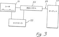
第3図は、本発明の電磁誘導機械カッタを示す概略的なブロック線図であり、
第4図は、本発明の電磁誘導機械カッタの1の実施例を示し、
第5図は、本発明の電磁誘導機械カッタの現在好ましい実施例を示し、
第6図は、現在好ましい実施例による、組合せの霧化された流体粒子をプログラムするための制御パネルを示し、
第7図は、流体圧に対する粒子サイズをプロットした曲線であり、
第8図は、流体圧に対する粒子速度をプロットした曲線であり、
第9図は、本発明による流体粒子、電磁エネルギ源およびターゲット面を示す概略図であり、
第10図は、本発明の「てき弾」効果を示す概略図であり、
第11図は、本発明の「爆発的放出」効果を示す概略図であり、
第12図は、本発明の「爆発的推進」効果を示す概略図であり、
第13図は、第10図から第12図の組合せを示す概略図であり、
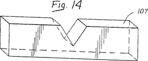
第14図は、本発明で得られる切断の「清浄度」を示す概略図であり、
第15図は、従来技術によるシステムで得られる切断の粗さを示す概略図であり、
第16図は、現在好ましい実施例のレーザ送出システムの断面図であり、
第17図および第17b図は、現在好ましい実施例のレーザ送出システムの部分的に分解した状態を示し、
第18図は、本発明による湾曲した結晶性ファイバを示し、
第19図は、レーザ源に接続可能な現在好ましい実施例によるレーザ送出システムの一部を示し、
第20図は、本発明による歯科/医療ワークステーションを示し、
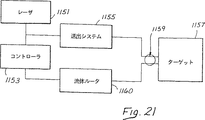
第21図は、本発明の1実施例による、調整された流体を用いる電磁カッタを示す概略的なブロック図であり、
第22a図は、本発明による機械的ドリリング装置を示し、
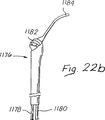
第22b図は、本発明によるシリンジを示し、
第23図は、本発明の流体調整システムを示し、
第24図は、本発明の流体調整ユニットの1実施例を示し、
第25図は、本発明の空気調整ユニットを示す。
現在好ましい実施形態の説明
第2図は、本発明による光カッタを示す。この光カッタ13は、第1b図に示した多くの在来の要素からなる。光集束部材35が、金属の2つの円筒状部材19、21間に配置される。光集束部材35は、ファイバガイドチューブ5からのレーザエネルギの望ましくない散逸を防止する。特に、ファイバガイドチューブ5からのエネルギは、光集束部材35によって集束されるのに先立って僅かに散逸される。光集束部材35は、ファイバガイドチューブ5からのエネルギをファイバガイドチューブ23内に集束する。ファイバガイドチューブ5からファイバガイドチューブ23へのレーザエネルギの効率的な伝達は、在来のエアナイフ冷却システム11(第1b図)の必要性を低下させる、というのは、レーザエネルギがほとんど消散されないからである。第1ファイバガイドチューブ5はトランク用ファイバーオプチック(光伝送性繊維)からなり、これは、フッ化カルシウム(CaF)、酸化カルシウム(CaO2)、酸化ジルコニウム(ZrO2)、フッ化ジルコニウム(ZrF)、サファイア、中空ウェーブガイド、液体コア、テックスグラス、クォーツシリカ、硫化ゲルマニウム、硫化ヒ素、および、酸化ゲルマニウム(GeO2)のうちの1つからなる。
第3図は、本発明による電磁誘導式機械カッタを示すブロック図である。電磁エネルギ源51は、コントローラ53と送出システム55との双方に連結される。送出システム55は、ターゲット面57に機械的な力を与える。現在実施されるように、送出システム55は、レーザ51をターゲット面57に配置された相互作用帯域59に導くための光ファイバガイドを有する。送出システム55は、更に、ユーザが特定した組合せの霧化された流体粒子を相互作用帯域59に送出するためのアトマイザを備える。コントローラ53は、レーザ51の種々の作動パラメータを制御し、更に、送出システム55から出力された、ユーザが特定した組合せの霧化された流体粒子の特性を制御する。
第4図は、本発明による電磁誘導機械カッタの簡単な実施例を示し、光ファイバガイド61と空気チューブ63と水チューブ65とが手持ちハウジング67内に配置される。水チューブ65は、比較的低圧で作用するのが好ましく、空気チューブ63は比較的高圧で作用するのが好ましい。光ファイバガイド61からのレーザエネルギは、相互作用帯域59における空気チューブ63と水チューブ65とからの空気と水との混合体に集束する。空気および水の混合体内の霧化された流体粒子は、光ファイバチューブ61のレーザエネルギからエネルギを吸収し、爆発する。これらの霧化された流体粒子の爆発力は、ターゲット57上に機械的な切削力を作用させる。
第1b図に戻ると、従来技術の光カッタは、例えば領域Aでターゲット面上にレーザエネルギを集束させ、本発明の電磁誘導機械カッタはレーザエネルギを例えば相互作用帯域Bに集束させる。従来技術の光カッタはレーザエネルギを直接使用して組織を切断し、本発明の電磁誘導機械カッタはレーザエネルギを使用して霧化された流体粒子を爆発させ、これによりターゲット面に機械的な切断力を作用させる。従来技術の光カッタは、関係する領域を切断するために大量のレーザエネルギを使用する必要があり、更に、この関係領域の冷却と切断組織の除去との双方を行うために大量の水を使用しなければならない。
これに対し、本発明の電磁誘導機械カッタは、比較的少量の水を使用し、更に、水から発生した霧化された流体粒子を爆発させるために僅かなレーザエネルギを使用するだけである。本発明の電磁誘導機械カッタによると、爆発した霧化流体粒子はターゲット面に接触する前に発熱反応で冷却されるため、手術領域を冷却する必要がない。したがって、本発明の霧化された流体粒子は過熱され、膨張し、ターゲット面に接触する前に冷却される。したがって、本発明の電磁誘導機械カッタは、炭化あるいは変色を生じさせることなく切断することができる。
第5図は、電磁誘導機械カッタの現在好ましい実施例を示す。霧化された流体粒子を発生させるアトマイザは、ノズル71を備え、このノズルは、他のノズル(図示しない)と交換し、所要の切断形式にしたがって種々の空間的分布を得ることができる。点線で示す第2のノズル72も用いることができる。電磁誘導機械カッタは、更に、ユーザコントロール部75で制御される。簡単な実施例では、ユーザコントロール部75は、ノズル71内に入る空気および水の圧力を制御する。したがって、ノズル71は、多くの異なるユーザが特定した組合せの霧化された流体粒子とエアロゾル化したスプレーとを作ることができる。
光ファイバガイド23から強いエネルギが放出される。この強いエネルギは、レーザ等のコヒーレント源から形成されるのが好ましい。好ましい実施例では、レーザは、レーザはエルビウム、クロミウム、イットリウム、スカンジウム、ガリウムガーネット(Er,Cr:YSGG)固体レーザであり、これは、2.70から2.80ミクロンの範囲の波長の光を発生する。現在好ましいものとして、このレーザは、ほぼ.78ミクロンの波長を有する。ノズル71が放出される流体は水が好ましいが、他の流体も使用でき、電磁エネルギ源の好適な波長は、流体が高度に吸収できるように選定することができる。
水以外の流体が使用されると、光エネルギの吸収が変化し、切断効率も影響を受ける。一方、顔料あるいは染料を含有する流体を使用する場合は、流体による吸収を高めるために、例えばネオジム、イットリウム、アルミニウム、ガーネット−Nd:YAGの波長を選択することができる。
他の利用可能なレーザシステムは、2.70から2.80ミクロンの範囲の波長の電磁エネルギを発生するエルビウム、イットリウム、スカンジウム、ガリウムガーネット(Er:YSGG)固体レーザ、2.94ミクロンの波長の電磁エネルギを発生するエルビウム、イットリウム、アルミニウムガーネット(Er:YAG)固体レーザ、2.69ミクロンの波長の電磁エネルギを発生するクロミウム、ツリウム、エルビウム、イットリウム、アルミニウムガーネット(CTE:YAG)固体レーザ、2.71から2.86ミクロンの範囲の波長の電磁エネルギを発生するエルビウム、イットリウムオルトアルミネート(Er:YALO3)固体レーザ、2.10ミクロンの波長の電磁エネルギを発生するホルミウム、イットリウム、アルミニウムガーネット(Ho:YAG)固体レーザ、266ナノメータの波長の電磁エネルギを発生するクォッドルプルドネオジム、イットリウム、アルミニウムガーネット(クォッドルプルドNd:YAG)固体レーザ、193ナノメータの波長の電磁エネルギを発生するアルゴンフルオリド(ArF)エキシマーレーザ、308ナノメータの波長の電磁エネルギを発生するキセノンクロリド(XeCl)エキシマーレーザ、248ナノメータの波長の電磁エネルギを発生するクリプトンフルオリド(KrF)エキシマーレーザ、および、9.0から10.6ミクロンの範囲の波長の電磁エネルギを発生する二酸化炭素(CO2)でもよい。水は、その生物学的適応性、豊富性および低コストであることから、好ましい流体として選択される。実際に使用する流体は、選択した電磁エネルギ源(すなわちレーザ)の波長に対して適性に調和(高度に吸収される意味)する限り、変えることができるものである。
電磁エネルギを送出する送出システム55は、光ファイバエネルギガイドあるいはこれと同等の部材を含み、レーザシステムに取付けられ、所要の作業位置まで延びる。光ファイバあるいはウェーブガイドは、典型的には長く、細く、軽量で、容易に操作することができる。光ファイバは、フッ化カルシウム(CaF)、酸化カルシウム(CaO2)、酸化ジルコニウム(ZrO2)、フッ化ジルコニウム(ZrF)、サファイア、中空ウェーブガイド、液体コア、テックスグラス、クォーツシリカ、硫化ゲルマニウム、硫化ヒ素、酸化ゲルマニウム(GeO2)およびその他の材料から形成することができる。他の送出システムは、ミラー、レンズおよび他の光学部材を備える装置を含み、エネルギは凹部を通って移動し、種々のミラーで導かれ、特別のレンズで、標的とされた切削部位に集束される第16第19図を参照して後述するように、本発明の医療用の光送出のための好ましい実施例は、光ファイバコンダクタを通して行われ、その理由は、光ファイバが軽量で、低コスであること、および、術者、歯科医師あるいは医師になじみやすいサイズおよび重量のハンドピースの内側に収容可能なためである。工業用の用途では非光ファイバシステムを使用することができる。
ノズル71は、選択した流体の小さな粒子の工学的組合せを形成するために用いられる。ノズル71は、液体のみ、空気ブラスト、空気アシスト、渦、ソリッドコーン等の種々の異なる構造を備えてもよい。流体が所定の圧力および速度でノズル71を出ると、ユーザが制御可能なサイズ、速度および空間的分布の粒子に変換される。
第6図は、霧化された流体粒子をユーザがプログラム可能にした制御パネル77を示す。例えば流体の圧力および流速を変更することにより、ユーザは、霧化された流体粒子の特性を制御することができる。これらの特性は、レーザエネルギの吸収効率を定め、これに続く電磁誘導機械カッタの切断効率を定める。この制御パネルは、例えば流体粒子サイズコントロール78、流体粒子速度コントロール79、コーンアングルコントロール80、平均出力コントロール81、反復率82およびファイバセレクタ83を備える。
コーンアングルは、例えばノズル71の物理的構造を変更することにより、制御することができる。例えば種々のノズル71を電磁誘導機械カッタ上で交換可能に配置することができる。これに代え、単一のノズル71の物理的構造を変更することも可能である。
第7図は、圧力に対する平均流体粒子サイズのプロット85を示す。この図によると、ノズル71を介する圧力が増大すると、霧化された流体粒子の平均流体粒子サイズが減少する。第8図のプロット87は、これらの霧化された流体粒子の平均流体粒子速度が、圧力の増加と共に増大することを示す。
本発明によると、従来の熱による切削力に代え、機械的な切削力でターゲット面から物質が除去される。レーザエネルギは、ターゲット物質上に機械的な力を誘導させるためにのみ用いられる。したがって、霧化された流体粒子は、レーザの電磁エネルギを、本発明の機械切断効果を達成するために必要な機械エネルギに変換する媒体として作用する。レーザエネルギ自体は、ターゲット物資で直接吸収されるものではない。本発明の機械的な相互作用は、安全で、迅速で、従来のレーザカッティングシステムでは典型的なものであった不都合な熱側効果(thermal side-effects)が排除される。
光ファイバガイド23(第5図)は、ターゲット面の極く近部に配置することができる。しかし、この光ファイバガイド23は、実際にはターゲット面に接触しない。ノズル71からの霧化された流体粒子は、相互作用帯域59内に配置されるため、光ファイバガイド23の目的は、レーザエネルギを相互作用帯域内に配置することである。本発明の新規な特徴は、サファイヤの光ファイバガイド23の形成である。しかし、光ファイバガイド23の成分に拘わらず、本発明の他の新規な特徴は、光ファイバガイド23上におけるノズル71からの空気および水の洗浄効果である。
本願出願人は、この洗浄効果は、ノズル71がある程度ターゲット面に直接的に向けられているときに、最適であることを見出した。例えば機械切削による破片が、ノズル71からのスプレーにより除去される。
更に、本願出願人は、ターゲット面を指すノズル71のこの配置は、本発明の切断効率を高めることを見出した。霧化された流体粒子は、それぞれターゲット面の方向に僅かな初期運動エネルギを有している。光ファイバガイド23からの電磁エネルギが霧化された流体粒子と接触すると、流体粒子の球状の外面が集束レンズとして作用し、このエネルギを水粒子の内部に集束させる。
第9図に示すように、水粒子201は照明側103と、影側105と、粒子速度107とを有する。集束された電磁エネルギは水粒子201で吸収され、水粒子の内部を加熱し、急速に爆発させる。この外熱による爆発は、爆発した水粒子201の残部を冷却する。周部の霧化された流体粒子は更に、爆発した水粒子201の部分を更に冷却する。この爆発で圧力波が形成される。この圧力波、および、爆発した水粒子201の運動エネルギを増大した部分は、ターゲット面107の方向に向けられる。大きな運動エネルギで高速移動する、元の爆発した水粒子201の随伴部分と圧力波とは、強く、集中した機械的な力をターゲット面107に作用させる。
これらの機械的な力は、「削り取り」作用を通じて物質面からターゲット面を破砕させる。ターゲット面107は、蒸発、崩壊あるいは炭化することがない。所要量の物質がターゲット面107から除去されるまで、本発明による削り取りプロセスが繰り返される。従来技術のシステムとは異なり、本発明は流体の薄い層を必要としない。実際、流体の薄い層がターゲット面を覆わないことが好ましく、これは絶縁層が上述の干渉プロセスを阻害するからである。
第10第11図および12は、霧化された流体粒子による種々の形式の電磁エネルギ吸収を示す。ノズル71は、流体粒子サイズが平均値の回りで狭い範囲に分布する状態に、霧化されたスプレーを製造するように形成するのが好ましい。切断効率を制御するためのユーザ入力装置は、簡単な圧力および流速計75(第5図)を備え、あるいは、例えば第6図に示すように制御パネルを備えることもできる。高分解能切断をユーザが入力すると、比較的小さな流体粒子がノズル71により形成される。低分解能切断を特定するユーザの入力に対して、比較的大きな流体粒子が形成される。ユーザ入力が深貫入切断を特定すると、ノズル71は比較的低密度で流体粒子を分布させ、ユーザ入力が浅貫入切断を特定すると、ノズル71は、流体粒子を比較的高密度で分布させる。ユーザ入力装置が、第5図の簡単な圧力および流速計75を備える場合は、高切断効率を特定するユーザの入力に応じて、比較的小さな流体粒子の比較的低密度の分布を発生させることができる。同様に、低切断効率を特定するユーザの入力に応じて、比較的大きな流体粒子の比較的高密度分布を発生させることができる。その他の変更も、可能である。
これらの種々のパラメータは、切断形式および組織の形式にしたがって調整することができる。硬質組織は、歯のエナメル質、歯のぞうげ質、歯のセメント質、骨、および、軟骨を含む。本発明の電磁誘導機械カッタが切断することのできる軟質組織は、皮膚、粘膜、歯肉、筋肉、心臓、肝臓、腎臓、脳、目、および、血管を含む。他の物質は、例えばガラスあるいは結晶質、および半導体チップ、面を含む。例えば骨組織の場合、癌に冒された骨の部分を、本発明の電磁誘導機械カッタで除去することができる。本発明の電磁誘導機械カッタは、最小のクロス汚染を有する清浄で高分解能の切断を提供し、したがって、癌に冒された骨を正確に除去することができる。骨が切断された後、回復の成功率は増大し、クロス汚染の可能性は減少する。
例えばガラスあるいは結晶質の場合、銀あるいは他の誘電材料をガラスあるいは結晶質の面に接着してミラーを形成する前に、ガラスあるいは結晶質の表面を酸を用いて通常のように準備する。従来の酸の使用は、不均一に表面と反応し、表面構造を変化することにより、僅かに表面を劣化させ、望ましくない。しかし、本発明の電磁誘導機械カッタは、均一な態様で表面から薄い層を除去するために使用でき、これにより、銀あるいはとの誘電物質を接着するための準備として表面を清浄にし脱脂する。本発明の電磁誘導機械カッタを表面上に使用することは、ガラスあるいは結晶質の顕微鏡組織を変化させるものではない。
半導体チップの場合、これらのチップはシリコンウェハーから形成される。シリコン結晶が成長した後、シリコン結晶がスライスされてシリコンウェハーとなる。多くの異なる加工工程が利用できる。1の例示的な工程で用いられる一連のサブステップによると、各シリコンウェハーは、通常の手段を用いて二酸化シリコンの層で被覆されている。最終目標は、ドーパントをシリコンウェハー内に選択的に配置し、これにより、同電路あるいは回路をシリコンウェハー内に形成することである。この目標を達成するため、二酸化シリコン層の一部が選択的に除去され、ここにドーパントが配置される。このドーパントは、ウェハーの全体の上に配置されるが、しかし、二酸化シリコンで覆われていないウェハーの一部のみがドーパントを受入れる。二酸化シリコン層で覆われた領域は、ドーパントが侵入せず、これはこの領域上のドーパントが二酸化シリコンの層により吸収されるからである。
ドーパントをシリコンウェハー内に導入する前に、二酸化シリコンの層の部分を選択的に除去するために、かなり複雑な工程が用いられる。二酸化シリコン層の部分を選択的に除去するために必要な第1工程は、一般にレジストと称される光感応ポリマー材料の被覆を施すことを含む。ウェハーが迅速に回転されるときにウェハーに数滴のレジストが付着され、レジストの均一な被覆を施し、乾燥される。次に、一部透明な写真ネガあるいはフォトマスクがウェハーの上に配置され、例えば顕微鏡を用いて整合される。フォトマスクは、ポジ型レジスト似ついては、二酸化シリコンが除去されるべき領域でのみ透明であり、ネガ型レジストについては逆である。この後、フォトマスクは紫外線あるいは近紫外線に露光される。フォトマスクの透明部分は、レジストの対応する部分に光を透過する。光を受けるレジストの領域は、構造的に変化し、光を受けてないレジストの領域(フォトマスクの下の領域)は影響をうけない。ネガ型レジストについては、レジストの照明されたレジストの分子は架橋される(重合される)。ポジ型レジストについては、照明されたレジストの分子結合が破壊される。レジストの重合されてない領域は、トリクロロエチレン等の溶媒を用いて溶解することができる。レジストの重合された領域は、耐酸性であり、したがって、溶媒で影響されず、したがってフォトマスクは酸化物の残留する保護被覆により、再現される。
しかし、残りのレジストは化学物質および水混合物で除去しなければならない。この化学物質および水混合物は、完全に除去し、シリコンウェハー上にレムナントが残留しないように完全に洗い落とされる。レジストと、化学物質および水混合物とが除去されると、イオン注入法を用いてシリコンウェハー内にドーパントが注入される。続いて、最初はレジストと化学物質および水混合物とで覆われていたシリコンウェハーの一部が、これにコンダクタを接着される。コンダクタが接着される前に、これらの領域に光酸エッチングが施され、これにより、シリコンウェハー面が僅かに粗くされ、接着性を改善する。
本発明の1の用途では、電磁誘導機械カッタは、二酸化シリコンの層を直接的に選択的エッチングするために用いることができる。このような用途では、電磁誘導カッタが二酸化シリコン層の上に直接集束され、これによりその一部を除去する。レジスト、フォトマスク、紫外線光、溶媒、化学物質および水混合物、および、酸はこの用途では必要でなく、これは、二酸化シリコン層の一部が電磁誘導機械カッタで直接除去されるからである。第6図の制御パネル77は、電磁誘導機械カッタのカッティング限界およびカッティング深さを制御する。例えばフォトマスクのイメージに対応するカッティングパターンを実行するための正確な設備は、電磁誘導カッタにより、二酸化シリコンの一部除去するのを制御するために使用することが好ましい。
本発明の他の用途では、電磁誘導機械カッタは、化学物質および水混合物に代えて、レジストの層を除去するために使用することができる。この用途では、化学物質および水混合物は必要なく、例えば水を節約することになる。更に、化学物質および水混合物が使用されないため、接着イオン注入のための極めて良好な汚染無しの面が形成される。この汚染無しの面は、シリコンウェハーのドーパント注入部にコンダクタを後から接着するのに適している。電磁誘導機械カッタは、例えば蒸留水からなる霧化された流体粒子を使用でき、これは比較的汚染物質がない。極めて浅い切断あるいは解離は、残りのレジストの層だけを除去するために形成することが好ましい。第6図の制御パネル77と組合わせて精密な設備を使用することは、除去する必要のあるレジストの領域に対応したシリコンウェハー上の浅い表面層除去パターンを具現するために好ましい。切断は、電磁誘導カッタの集束されたカッティングビームを使用して行い、あるいは、電磁誘導機械カッタのカッティングビームは、チップのより大きな部分を覆うために分散してもよい。例えば、集束されたカッティングビームはレジストの部分を横切って迅速にスキャンし、あるいは、より大きなデフォーカスされたカッティングビームあるいは多数のビームを、レジストの部分上をスキャンすることなく、スキャンしあるいは作用させてもよい。
CMOS,バイポーラ,C4および他のマルチチップモジュールあるいはフリップチップ技術を含む広範囲の種類の他の半導体チップ製造工程も利用可能であり、レジスタ、トランジスタおよびキャパシタを含む種々の能動および受動素子を製造するために使用することができる。更に、ブァイアホール等の他の非素子エレメントの製造に、本発明の電磁誘導機械カッタを使用することもできる。この電磁誘導機械カッタは、これらの工程あるいは他の同様な工程で、種々の物質のいずれをも切断あるいは除去するために使用することができる。
ユーザは、ノズル71から出る組合せの霧化された流体粒子を調節して、光ファイバ23(第5図)を効率的に冷却および洗浄することができる。本発明の好ましい実施例によれば、組合せの霧化された流体粒子は、光ファイバガイド23を効果的に冷却すると共に、同時に、手術現場で導入される可能性のある特定の破片の無い状態に、光りファイバガイド23を維持する分布、速度および平均径を備えることができる。
第9図を再度見ると、電磁エネルギは、各霧化された流体粒子101の照明された側103で接触し、霧化された流体粒子を所定深さまで貫通する。集束された電磁エネルギは、流体に吸収され、霧化された流体粒子101の爆発的な蒸発を誘導する。
霧化された流体粒子の径は、入射電磁エネルギの波長よりも小さくするか、ほとんど同じか、あるいは、それよりも大きくすることができる。これらの3つの場合のそれぞれでは、電磁エネルギと霧化された流体粒子との間に、異なる相互作用が発生する。第10図は、霧化された流体粒子の径が電磁エネルギの波長よりも小さい場合を示す(d<λ)。この場合は、流体粒子101の内側の前流体量がレーザエネルギを吸収し、爆発的な蒸気化を誘導する。流体粒子101は、爆発し、その内容物を放射状に放出する。本願出願人は、この現象を、「爆発的グレネード」効果と称する。この相互作用により、爆発から半径方向圧力波が形成され、伝播方向に形成および突出する。伝播の方向は、ターゲット面107に向き、現在好ましい実施形態では、レーザエネルギと霧化された流体粒子との双方がほぼ伝播方向に移動する。
水粒子101の爆発および圧力波によって生じた部分は、ターゲット面107から物質を切断および除去する「削り取り」効果を生じさせる。したがって、第10図に示す「爆発的グレネード」効果によると、流体粒子101の小さな径は、レーザエネルギの貫通を可能とし、液体の全量内で激しく吸収可能とする。流体粒子101の爆発は、放射状にエネルギおよび破片を放出する爆発的グレネードと類推することができる。流体粒子101の水分は、少量の液体内における強力な吸収により蒸発され、この工程で形成された圧力波は、物質切断工程を形成する。
第11図は、流体粒子101が電磁エネルギの波長とほぼ等しい径を有する場合を示す(d≒λ)。この「爆発的放出」効果によると、レーザエネルギは内部の流体で吸収される前に、流体粒子101を通して移動する。一度吸収されると、流体粒子の影になった側が加熱され、爆発的な蒸発が生じる。この場合、内部粒子流体は流体粒子の影になった側を通して猛烈に噴出され、爆発的な圧力波と共にターゲット面に向けて急速に移動する。第11図に示すように、レーザエネルギは流体粒子101を貫通し、粒子径のサイズに近い深さに吸収される。第11図に示す場合の爆発的な蒸発の中心は、移動する流体粒子101の影になった側105に近接する。第11図に示す「爆発的放出」効果によると、蒸発した流体は、粒子の影になった側を通してターゲット面107に向けて猛烈に放出される。
第12図に示す第3のケースは、「爆発的推進」効果である。この場合、流体粒子の径は、電磁エネルギの波長よりも大きい(d>λ)。この場合、レーザエネルギは、照射面103を通して僅かな距離のみ流体粒子101を貫通し、この照射された面103を蒸発させる。照射された面103の蒸発は、流体粒子101の残部をターゲットにされた物質の面107に向けて推進しようとする。したがって、初期の流体粒子101の質量の一部が運動エネルギに変換され、これにより、流体粒子101の残部をターゲット面に向けて大きな運動エネルギで推進する。この大きな運動エネルギは、流体粒子101の初期運動エネルギに対する添加剤である。第12図に示す効果は、ジェットテールを有する微細水ロケットとして視覚化することができ、これは、粒子がターゲット面107に向けて高速で推進するのを支援する。照射側103で爆発する蒸気は、粒子の初期の前方への速度をこのように追加する。
第10図から第12図を組合わせた状態を第13図に示す。ノズル71は、相互作用帯域59に搬送される組合せの霧化された流体粒子を形成する。レーザ51がこの相互作用帯域59に集束される。比較的小さな流体粒子131が「グレネード」効果を介して爆発し、比較的大きな流体粒子133が「爆発的推進」効果を介して爆発する。中間サイズの流体粒子は、レーザ51の波長とほぼ等しい径を有し、参照符号135で示してあり、「爆発的排出」効果を介して爆発する。これによる圧力波137および爆発した流体粒子139は、ターゲット面107に衝突する。
第14図は、本発明の電磁誘導機械カッタで形成されたクリーンな高分解能切断を示す。第15図に示す従来技術による切断と異なり、本発明の切断はクリーンで正確である。特に、この切断は理想的な結合面を形成し、正確で、切断部の周囲の物質に応力を残留させない利点がある。
第16図を参照すると、医療用の光を供給する現在好ましい実施例は、医療用ハンドピース203内に収容された光ファイバコンダクタあるいはトランクファイバ201を備える。医療用ハンドピース203は、シャフトアセンブリ209を収容する細長い孔207を有するスリーブハウジング205を備える。シャフトアセンブリ209は、トランクファイバ201を収容し、この好ましい実施例では、このファイバは1またはそれ以上のジャケット211で包まれている。ジャケット211はトランクファイバ201の回りに密に形成されている。ジャケット211に加え、内側保護チューブ213と外側保護チューブ215とがトランクファイバ211の回りに配置されている。ジャケット201とは対照的に、内側保護チューブ213と外側保護チューブ215とは、トランクファイバ201の上に摺動可能に配置されている。本発明によると、内側保護チューブ213と外側保護チューブ215は、トランクファイバ201に強度を付加し、トランクファイバ201に曲げあるいは他の応力の作用による損傷あるいは破損を防止する。例えば現在具体化されているように固定用フェルール(permanent ferrule)217は、トランクファイバ201およびジャケット211のみを収容し、剛性材料から形成されている。トランクファイバ201に曲げあるいは他の応力が作用すると、通常と同様にトランク用ファイバ201は、固定用フェルール217内あるいはこのフェルール217の近部で破損する危険が高くなる。内側保護チューブ213および外側保護チューブ215は、トランクファイバ201の大きな表面領域を横切ってこのトランク用ファイバ201に曲げおよび他の応力を生じさせる力を分散し、これにより、トランク用ファイバ201の破損の危険を減少させる。先に具体化したように、内側保護チューブ213は、固定用フェルール217およびSMAコネクタ341の双方に固定(好ましくは接着して)されるが、しかし、外側保護チューブ215は、SMAコネクタ341にのみ固定され、固定用フェルール217に当接する。内側保護チューブ213は固定用フェルール217とSMAコネクタ341との双方に固定し、固定用フェルール217とSMAコネクタ341とが相対的に回転したときに、トランク用ファイバ201の回転を防止するのが好ましい。したがって、これらの2つの保護チューブ213,215は、互いに、および、ジャケット211の双方の上を摺動することができる。ここでは、2つの保護チューブ213,215が用いられているが、所要の操作パラメータにしたがって単一の保護チューブを用い、3つあるいはそれ以上の保護チューブも用いることも可能である。保護チューブは、プラスチック材料で形成されるのが好ましいが、しかし、金属あるいはテフロン(Teflon)で形成することもできる。
固定用フェルール217は、外側ハウジングを介してシャフトアセンブリ209に固定され、この外側ハウジングは空気調整インプットチャンバ221を規定する。この空気調整インプットチャンバ221は、第1b図のエアナイフライン11と同様であり、空気調整インプットチャンバ221はトランクファイバ201の先端部と、固定用フェルール217と、中間フェルール225と、湾曲したファイバチップ227とを冷却するインターフェース223に空気を供給する。固定用フェルール217と中間フェルールとは、スペーサ226で分離されている。空気は、空気調整インプットチャンバ221を通して、矢印A1,A2の方向に進み、固定用フェルール217内の全体を符号231,233で示す複数のドリル孔を通過する。空気調整インプットチャンバ221からの空気は、ドリル孔231,233からインターフェース223内に流れ、このインターフェース223から空気冷却排気チャンバ241内に流れる。空気は、空気冷却排気チャンバ241を通って矢印A3,A4の方向に流れ、医療用ハンドピース203を戻る。先に具体化したように、空気調整インプットチャンバ221および空気冷却排気チャンバ241は、共に角張って形成され、同心状である。
本発明によると、固定用フェルール217と中間フェルール225とスペーサ226とは、セラミック等の耐熱材料を備える。この耐熱材料は、固定用フェルール217と中間フェルール225とスペーサ226とのより高い温度での作動を容易とし、したがって、空気調整インプットチャンバ221と空気冷却排気チャンバ241とを通る空気量をより少なくすることができる。固定用フェルール217と中間フェルール225とスペーサ226とは、サファイヤ等の結晶質物質を備えてもよい。ファイバ対ファイバの継手246は、中間フェルール225を囲み、中間フェルール225と同様な適宜の耐熱材料を備え、あるいは、これに代えてアルミニュウムあるいはステンレス鋼等の金属を備えてもよい。
光エネルギは、トランクファイバ201の先端部から湾曲したファイバチップ227の基端部に連結される。湾曲したファイバチップ227は所要の湾曲を形成し、したがって、例えば光ファイバに曲げによる応力あるいは歪みを形成することを要しない。本発明によると、湾曲したファイバチップ227は、結晶質物質から形成され、所定角度の湾曲形状に装備する前に、予備成形される。
第18図に示すように、湾曲したファイバチップ227の現在好ましい実施例は、ほぼ30ミリメートルの第1長さ256と、ほぼ20ミリメートルの第2長さ259と、ほぼ90度の角度261とを有する。半径方向長さ263は、10ミリメートルであるのが好ましい。本発明によると、結晶質ファイバ227は、ほぼ2000度の火炎の下で、手で曲げられる。湾曲したファイバチップ227は、凹部270(第16図)内に嵌合し、この凹部は湾曲部272に拡大凹部領域を有し、僅かな製造上のずれを持つファイバチップ227を収容する。湾曲した結晶質物質は、この湾曲した結晶質物質が理想的な光学的な性質を有することを確認するために、引続きテストすることが必要である。湾曲したファイバチップ227の現在好ましい実施例はほぼ90度の角度を有するが、しかし、設計上の選択にしたがって、ゼロから180度の1あるいはそれ以上の角度および他の異なる形状を有するものに製造することもできる。更に、現在好ましい実施例による湾曲したファイバチップ227は、中間フェルール225から先端フェルール275まで延在するが、他の種々の形状とすることも可能である。一例として、小径の可撓性湾曲結晶質ファイバを、レーザ光源(図示しない)および標準の小型タイプA(SMA)コネクタ341(第19図)から先端フェルール275まで延設してもよい。現在具体化されるものとして、湾曲したファイバチップ227はサファイヤを備え、このサファイヤは、本発明によればほぼ3ミクロンのオーダーの波長を搬送するために理想的なものである。現在好ましい実施例では、サファイヤから形成された湾曲したファイバチップ227は、2.78および2.94ミクロンの波長を導く。サファイヤに加え、設計上のパラメータにしたがって、光エネルギを導くために好適な他の結晶質物質を用いることもできる。
チップフェルール275は、湾曲したファイバチップ227を、医療用ハンドピース203の放射出口端の近部の所定位置に固定する状態に保持する。先端フェルール275は、固定用フェルール217および中間フェルール225を参照して上述したような耐熱材料を備えることができる。空気ライン277および水ライン279は、スリーブハウジング205内に配置され、スリーブハウジング205の放射出口端とキャップ284とで規定される混合チャンバ281内に、空気と水とを送出する。空気ライン277および水ライン279からの空気と水とは、混合チャンバ281内で空気アシストスプレーを形成する。この空気アシストスプレーは、湾曲したファイバチップ227の出口端に沿って矢印A5,A6の方向に、この混合チャンバ281から排出される。
本発明の他の特徴によると、光エネルギを導くために好適な他の結晶質物質を、インターフェース223の近部で湾曲したファイバチップ227の回りに配置することができる。この追加の結晶質物質は、中間フェルール225を備え、あるいは、これに代えて、インターフェース223の近部で湾曲したファイバチップ227の回りに配置され、更に中間フェルール225で囲まれる円筒状の結晶質物質でもよい。例えば、トランク用ファイバ201の径よりも小径の湾曲したファイバチップ227を形成することが望ましい場合もある。トランク用ファイバ201は、例えば強度を高めるために比較的大径に形成することができる。湾曲したファイバチップ227が、例えば50ミクロン等の極めて小径である場合には、インターフェース223の近部のこの湾曲したファイバチップ227の近位端部がトランク用ファイバ201の先端部から出力される比較的大量のエネルギで損傷する可能性がある。インターフェース223の近部で湾曲したファイバチップ227の回りに配置される追加の環状結晶質ファイバは、湾曲したファイバチップ227の損傷に対する保護を支援する。湾曲したファイバチップ227の近位端部の回りに1又はそれ以上の環状結晶質ファイバを配置し、これらの環状結晶質ファイバのそれぞれを中間フェルール225に長さに沿ってあるいはより長く延設してもよい。現在好ましいように、これらの環状結晶質フェルール225の1又はそれ以上が用いられるときには、シール付き通路301,303,304,306,309,311のいずれかを開いて追加空気を流通させかつこれで冷却するのを容易にすることができる。本発明によると、これらの通路301〜311のいずれかを開くことで、湾曲したファイバチップ227に沿って混合チャンバ281内に導かれる空気流路を更に容易にする。
第17a図および第17b図は、本発明による医療用ハンドピース203を示し、シャフトアセンブリ209はスリーブハウジング205の細長い孔207から取外してある。現在具体化されるように、カラー316(第16図)にねじ318が設けられている。このカラー316のねじ318は、スリーブハウジング205の近位端部ねじ320と係合し、カラー316が半径方向内方に向く力をスリーブハウジング205に作用させることができる。これらのカラー316からスリーブハウジング205上に半径方向内方に向く力は、細長い孔207内のシャフトアセンブリ209に摩擦係合し、シャフトアセンブリ209がスリーブハウジング205の細長い孔207内で移動するのを防止する。
第19図は、第16図の医療用ハンドピース203にリソースを供給する多くの部材を示す。水ライン326は、医療用ハンドピース203の水ライン279に水を供給することができる。同様に、空気ライン328は、空気ライン277に空気を供給することができ、空気調整ライン330は空気調整チャンバ221に空気を供給することができる。照明及び/又は投薬ケーブル332は、医療用ハンドピース203の照明及び/又は投薬ライン334に照明及び/又は投薬をなすことができる。医療用ハンドピース203は第1b図に示すようなレーザカッティングアセンブリと共に操作するように記載してあるが、医療用ハンドピース203の全体好ましい実施例は、第5図に示すものと同様なヘッドを有する電磁誘導機械カッタと共に作動する。現在好ましい実施例によると、空気ライン277および水ライン279は、第5図に示すヘッドアセンブリの空気チューブ63および水チューブ65と対応するのが好ましい。この現在好ましい実施例では、第16図のキャップ284は必ずしも必要なものではない。1の実施例では、空気チューブ63に対応する空気ライン277は使用されない。
現在好ましい湾曲したファイバチップ227の先端部がターゲット面に密に近接して配置されるため、照明ライン334(第16図)を通るコヒーレントあるいは非コヒーレント照明の光源が極めて有益である。一方、伝統的なレーザカッティング機構が用いられる場合は、照明ライン334からの照明が有益なものとはならず、通常の照準ビームを照明ライン334を通して導くことができる。
照明及び/又は投薬ライン334は、投薬ラインのみ備えてもよく、あるいは、照明ラインと投薬ラインとの双方を備えてもよい。投薬ラインは、患者のターゲット領域に対する麻酔薬等の薬物の導入を容易とする。
第19図を参照すると、トランク用ファイバ201とジャケット211とが、小型の総合タイプA(sum miniature type A(SMA))コネクタ341内に固定されている。このSMAコネクタは、レーザ光源(図示しない)内にトランク用ファイバ201とジャケット211とを導入しかつ固定することを容易とする。
内側保護チューブ213と外側保護チューブ215とは医療用ハンドピース203からSMAコネクタ341まで延び、SMAコネクタ341のインターフェースでトランクファイバ201に対する同様な保護機能を提供する。上述のように、1の保護チューブだけが使用されるか、あるいは、これに代えて、3あるいはそれ以上の保護チューブを使用することができる。現在好ましい実施例では、金属チューブ352が内側保護チューブ213と外側保護チューブ215とを囲み、追加の外側プラスチックチューブカバー355が金属チューブ352を囲む。
プラスチック保護カバー357は、トランク用ファイバ201を囲むこれらの部材を収容する。現在好ましい実施例では、プラスチック保護カバー357は、水ライン326と空気ライン328と空気調節ライン330と照明及び/又は投薬ケーブル332に固定され、医療用ハンドピース203に極近接して案内される。金属チューブ352と外側チューブカバー355とは医療用ハンドピースまで延びず、SMAコネクタ341から短い距離で終端するのが好ましい。もちろん、設計上のパラメータにより、他の距離に設定してもよい。パワーキャップ372および把持可能なノブ374は、更にトランク用ファイバ201をレーザ光源に取付けるのを容易とする。
本発明の歯科/医療用ワークステーション1111が第20図に示してある。この歯科/医療用ワークステーション1111は、通常の空気ライン1113と通常の水ライン1114とを有し、それぞれ空気と水とを供給する。真空ライン1112と電気口1115とが負圧の空気圧と電気とを、第1a図に示す真空ライン8および電気ライン14と同様に、歯科/医療用ユニット1116に供給する。流体調整ユニット1121は、これに代え、例えば歯科/医療用ユニ1116と機器1117との間に配置することができる。本発明によると、空気ライン1113と水ライン1114とは双方共流体調整ユニット1121に接続される。
コントローラ1125は、ユーザが入力し、空気ライン1113からの空気と水ライン1114からの水との一方あるいは双方が流体調整ユニット1121により調整されるように制御することができる。例えばコントローラ1125の構造にしたがい、流体調整ユニット1121により種々の薬剤を空気あるいは水に添加することができ、これにより、空気あるいは水が歯科/医療用ユニ1116に送られる前に、空気あるいは水を調整する。例えば21C.F.Rセクション172.510からセクション172.515に記載のような芳香剤および関連する物質を使用することもでき、この詳細は参照することにより本明細書に組込まれるものである。例えば21C.F.Rセクション73.1からセクション73.3126に開示されているように、例えば色彩も調整用に使用してもよい。
第1a図に示す機器18と同様に、機器1117は、電気焼灼器、電磁エネルギ源、レーザ、機械ドリル、機械のこぎり、カナルファインダ、シリンジ、及び/又は吸引器とを備えることができる。これらの機器1117の全ては空気ライン1113からの空気及び/又は水ライン1114からの水を使用し、コントローラ1125の構造にしたがって調整されあるいは調整されない。これに代え、機器1117のいずれも、流体調整ユニット1121に直接接続し、あるいは、空気1113、水1114、真空1112及び/又は電気1115ラインの何れかに直接接続することができる。例えば、点線で示すレーザ1118および送出システム1119は流体調整ユニット1121に接続される。レーザ1118aおよび送出システム1119aは、機器1117とグループを形成することに代え、歯科/医療ユニット1116に接続することができる。
第21図に示すブロック線図は、例えば第20図の空気1113、水1114、および電力1115の各ラインに直接接続されたレーザ1151の1の実施例を示す。この実施例では、別個の流体調整システムが用いられている。4つの供給ライン1113−1115のいずれかあるいは全てに直接接続されかつ独立した流体調整ユニットを有するレーザあるいは他のいずれかのツールの代りとして、これらのツールのいずれかは、これに代えあるいは更に、歯科/医療用ユニット1116あるいは流体調整ユニット1121に、あるいはこれらの双方に接続することができる。
第21図に示す例示的な実施例によると、電磁誘導機械カッタがカッティングに使用される。このカッタの詳細は本願出願人に譲渡された同時継続中の米国特許出願第08/522,503号に開示されている。電磁カッタのエネルギ源1151は、出力端1115(第20図)に直接接続され、コントローラ1153および送出システム1155の双方に連結されている。送出システム1155は、レーザ1151を導きかつ集束させる。通常のレーザシステムの場合は、ターゲットに熱的な切断力が与えられる。送出システム1155は、ターゲット面1157の上に位置する相互作用帯域1159内にレーザ1151を導く光ファイバガイドを備えるのが好ましい。流体ルータ1160は、ユーザが特定した組合せの霧化された流体粒子を相互作用帯域1159に送出するためのアトマイザを備えるのが好ましい。本発明によると、霧化された流体粒子は、調整され、後述するように、フレーバ、芳香、塩類および他の物質を備えることができる。
通常のレーザの場合、調整された流体の流れあるいはミストは、流体ルータ1160で供給される。コントローラ1153はレーザ1151の種々の作動パラメータ、流体ルータ1160からの流体の調整、および、流体ルータ1160からの流体の特性を制御することができる。
本発明は、例えば通常のドリルおよびレーザと共に使用できるものであるが、1の好ましい実施例は電磁誘導機械カッタである。他の好ましい実施例は、電気焼灼器、シリンジ、吸引器、又は、空気あるいは電気ドライバ、ドリル、充填あるいは洗浄の機械的な機器を含む。第4図は電磁誘導機械カッタの簡単な実施例を示し、光ファイバガイド61と空気チューブ63と流体チューブ65とが手持ちハウジング67内に配置されている。種々の接続が可能であるが、空気チューブ63と水チューブ65とは、第20図の流体調整ユニット1121あるいは歯科/医療用ユニット1116の一方に接続するのが好ましい。流体チューブ65は、比較的低圧下で作動するのが好ましく、空気チューブ63は比較的高圧下で作動するのが好ましい。
本発明によると、空気チューブ63からの空気あるいは流体チューブ65からの流体の一方あるいは双方が、コントローラ1125で制御されるため、流体調整ユニット1121により選択的に調整される。
第22a図に示す機械ドリル1161は、ハンドル1162とドリルビット1164と水出口1165とを備える。この機械ドリル1161は、電気あるいは加圧空気で駆動可能なモータ1168を備える。
モータ1168が例えば空気で駆動される場合、流体は第1供給ライン1170を介して機械ドリル1161内に入る。第1供給ライン1170を介して入る流体は、例えばタービンを備えるモータ1168を通して流れ、これにより、ドリルビット1164に回転力を与える。患者の味覚及び/又は臭いを感じさせることのない流体の一部がドリルビット1164の回りから排出され、患者の口及び/又は鼻に接触するようになる。流体の多くは、第1供給ライン1170を通して戻る。
例えば電気モータの場合、第1供給ライン1170は電力を提供する。第2供給ライン1174は、流体出口1166に流体を供給する。機械ドリル1161に供給された水及び/又は空気は、コントローラ1125の構造にしたがって、流体調整ユニット1161で選択的に調整することができる。
第22図に示すシリンジ1176は、空気入口ライン1178と水入口ライン1180とを備える。ユーザコントロール1182は、第1位置と第2位置との間を移動することができる。第1位置は、空気ライン1178からの空気を出力チップ1184に供給し、第2位置は、水ライン1180からの水を出力チップ1184に供給する。空気ライン1178からの空気と水ライン1180からの水との一方あるいは双方は、例えばコントローラ1125の構造にしたがって、流体調整ユニット1121で選択的に調整することができる。
第23図に転じると、流体調整ユニット1121(第20図)の一部が示されている。この流体調整ユニット1121は、例えばドリリングおよびカッティング手術における通常の水道水に代えて、歯科/医療用ユニット1116に調整された流体を供給するため、現存の水ライン1114に適用可能であることが好ましい。インターフェース1189が現存の水ライン1114に接続し、流体流入ライン1181およびバイパスライン1191を通して水を供給する。リザーバ1183は、流体流入ライン1181からの水を受入れ、調整された流体を流体流出ライン1185に送出する。流体流入ライン1181、リザーバ1183および流体流出ライン1185は共に流体調整用サブユニット1187を備える。
調整された流体は、流体調整サブユニット1187から混合ユニット1193内に入る。例えばタブレット、液体シロップ、あるいはフレーバカートリッジ等の通常の手段により、この流体を調整することができる。更に、混合ユニット1193内には、バイパスライン1191から通常の水が供給される。例えばコントローラ1125内へのユーザ入力部は、例えば、混合ユニット1193から流体チューブ1165への流体出力が、流体流出ライン1185からの調整された流体のみか、バイパスライン1191からの通常の水のみか、あるいは、これらの混合体であるかどうかを定める。ユーザ入力部1195は、回転可能なノブ、ペダル、あるいは、フットスイッチを備え、調整された流体と通常の水との比率をユーザの操作で定めることができる。これらの比率は、ペダルあるいはノブの位置にしたがって定められる。例えばペダルの実施例では、完全に踏込んだペダル位置は、流体流出ライン1185からの調整された流体だけが流体チューブ1165に送られる状態に対応し、完全に上昇したペダル位置は、バイパスライン1191からの水だけが流体チューブ1165内に送られる状態に対応する。バイパスライン1191、混合ユニット1193およびユーザ入力部1195は多用性を与えるものであるが、実用的見地にしたがって省略することもできる。流体を調整するための簡単な実施例は、流体調整サブユニット1187だけを備える。
流体調整サブユニット1187の他の実施例が第24図に示してある。流体調整サブユニット1287は、空気ライン1281を介して空気ライン1113から空気を入力され、調整された流体を流体出力ライン1285を介して出力する。流体出力ライン1285は、リザーバ1283内を垂直に降下し、この内部の流体1291内まで延びるのが好ましい。蓋1284が取外され、調整された流体がリザーバ1283内に挿入される。これに代え、リザーバ1283内にすでにある水に、固体あるいは液体の形態の流体調整剤を添加してもよい。流体は、芳香流体滴あるいは芳香タブレット(図示しない)を用いて調整するのが好ましく、例えば抗菌(fungible)カートリッジで供給することができる。
リザーバ1283内の流体は、フルーツの香りあるいはミントの香り等の所要の香りに調整し、あるいは、空気を新鮮にする匂い等の所要の芳香に調整することができる。芳香、芳香をつけられたミスト、あるいは芳香をつけられた空気源を有する調整された流体は、第25図に示しかつ後述するように、空気調整ユニットとの関連で具体化するために特に有益である。香りおよび芳香に加え、他の調整剤も、通常の水ライン、ミストラインあるいは空気ラインに選択的に追加してもよい。例えば、塩水等のイオン化された溶液あるいは着色された溶液を後述するように添加することもできる。更に、ドリリングあるいはカッティング中に供給される水及び/又は空気の密度、比重、pH、温度、あるいは粘度を変更するために、薬剤を添加することができる。抗生物質、ステロイド、麻酔薬、抗炎症剤、殺菌剤、アドレナリン、エピネフリンあるいは収斂剤等の薬剤を、ドリリングあるいはカッティング術中に使用する水及び/又は空気に添加することができる。例えば収斂剤は、出血を少なくするために、水ラインを介して手術領域に送られる。ビタミン、ハーブあるいはミネラルも、カッティングあるいはドリリング術中に使用される空気あるいは水を調整するために使用することができる。手術傷に送られる麻酔剤あるいは抗炎症剤は、患者の不快あるいは創傷に対する損傷を減少し、抗生物質あるいは殺菌剤は、創傷の感染を防止する。
第25図に示す空気調整ユニットは、インターフェース1386,1389を介して現存する空気ライン1113に接続することができる。通常の空気は空気入口ライン1381を介して調整サブユニットに入り、空気出口ライン1385に出る。空気入口ライン1381は、リザーバ1383内に垂直に延び、このリザーバ1383内の流体1391中に延びるのが好ましい。この流体1391は、芳香流体滴あるいは芳香タブレット(図示しない)を用いて調整するのが好ましい。流体1391は、水の調整に関して上述したような他の物質で調整することもできる。本発明によると、通常のレーザカッティングシステム(第1b図)の水ライン1131内の水あるいは空気ライン1132内の空気が調整される。現在好ましいように、電磁誘導機械カッタの流体チューブ65あるいは空気チューブ63(第4図)が調整される。レーザ手術に加え、歯科のドリリング、洗浄、吸引、あるいは電気焼灼システムの空気及び/又は水も調整することができる。
上述の調整物質の多くは、現在好ましい実施例の電磁誘導機械カッティング環境における霧化された流体粒子内の電磁エネルギの吸収を変化させる。したがって、調整の形式は、電磁あるいは電磁誘導機械カッタのカッティングの出力に影響を与える。したがって、フレーバあるいは投薬などの上述の種々の調整物質を通じて達成可能な直接的な利点に加え、これらの種々の調整物質は、電磁あるいは電磁誘導機械カッタによる切断の形式に多用性とプログラム可能性とを与える。例えば、塩溶液の導入はカッティングの速度を低下する。このような生体適合可能な塩溶液は、微妙なカッティング手術に使用でき、あるいは、より高いレーザ出力に設定して、通常の水で達成可能なカッティング出力を近似させて使用することもできる。
本発明によると、着色した流体も電磁あるいは電磁誘導機械カッタに用いることができる。電磁エネルギ源は、例えば所定の着色を有する霧化された流体粒子の最大吸収に設定することができる。これらの着色された霧化された流体粒子は、機械カッティングに用いることができる。カッティング手術に、第2の水あるいはミスト源が使用されるが、しかし、この第2の水あるいはミストは着色されてないため、電磁エネルギ源との相互作用が最小となる。多くの例の内の1の例としてのみであるが、この第2のミストあるいは水源は香りを付けてもよい。
他の構造によると、霧化された流体粒子は、無着色であり、電磁あるいは電磁誘導エネルギ源は、これらの無着色の霧化された流体粒子に対して最大エネルギ吸収を形成するように設定することができる。そして、第2の着色された流体あるいはミストが手術領域に導入され、この第2のミストあるいは水は電磁エネルギ源と大きく相互作用することがない。他の例として、単一の霧化された流体粒子源を、着色および無着色との間で切換え、電磁エネルギ源を、1又は2つの着色状態によって吸収されるように設定し、これにより、カッティングが達成されるときに正確に制御可能な寸法を提供する。
殺菌剤は、空気および水ライン内、および歯科手術室の表面でのバクテリアの成長と戦うために空気あるいは水源に添加することができる。例えば歯科ユニット1116の空気および水ラインは、コントローラ1125で選定されかつ流体調整ユニット1121で供給される殺菌剤で定期的に洗うことができる。アクセサリチューブ殺菌ユニット1123が殺菌剤カートリッジを収容し、標準化されあるいは予めプログラムされた定期的な洗い流し作動を行うことができる。
歯科あるいは医療用処置においても、好適な殺菌剤を使用することができる。殺菌剤は、例えば歯科処置の終わりに口内洗浄として行うこともでき、又は、医療あるいは歯科処置中に施すこともできる。例えば患者の口内で切断されあるいは穴あけされた組織を冷却するために使用される空気および水は、ある程度は空気中に気化される。本発明によると、調整された殺菌剤溶液も、空気あるいは水と共に気化され、歯科手術室内の歯科用装置の表面上に凝縮する。これらの湿った表面上におけるバクテリアの成長は、この表面上の殺菌剤により大きく抑制される。
本発明の例示的な実施例について図示しかつ説明してきたが、当該分野の通常の技術者であれば、本発明の精神および範囲から逸脱することなく、多くの変更、変形および置換が可能である。 Background of the Invention
The present invention relates generally to devices suitable for acting on hard and soft materials, and in particular, a device for combining electromagnetic and water energy to cut and remove both hard and soft tissue, and , To a system for introducing conditioned fluid into a cutting, irrigation, aspiration, washing and drilling system.
A conventional dental / medical workstation 6 is shown in FIG. 1a. A vacuum line 8 and an
The dental /
The electromagnetic energy source is typically a laser coupled to a delivery system. These lasers 20a and delivery system 22a, both shown in dotted lines, and any of the devices described above can be directly coupled to the dental /
The laser 20 and delivery system 22 typically comprise a dental electromagnetic cutter. A typical conventional electromagnetic cutter is shown in FIG. According to this prior art device, the
When the
Pressurized air from the air knife line 11 surrounds and cools the laser as it bridges the gap between the two metal
Laser energy exits the
Water is generally used to cool the target surface by various laser cutting techniques. In addition, water is used during the mechanical drilling procedure to cool the target surface, from which the cut or perforated material is removed. Many prior art cutting or drilling systems mix a mixture of air and water, usually in the form of a fine mist, and are used to cool the target surface and / or remove cutting material from the target surface.
The use of water in these prior art systems has been somewhat successful for the limited purpose of cooling the target surface or removing debris therefrom. However, the water used in the prior art in cutting and drilling procedures cannot be diverted in addition to the two functions of cooling and debris removal. In particular, dosing treatments during cutting or drilling procedures, application of preventive measures, and aesthetically pleasing substances such as flavor or fragrance cannot be applied or used. Conventional drilling procedures are advantageous, for example, from the use of anesthesia when the drilling procedure is approaching, but only water and / or air has been used during this drilling procedure. In the case of laser cutting surgery, a bactericidal agent such as iodine is applied to the target surface during drilling to protect against infection, but no additional bactericidal agent is applied during such laser cutting surgery. In the case of drilling or cutting in the oral cavity, an unpleasant taste or odor develops, which makes the patient uncomfortable. The conventional method of using only water during this intraoral operation does not mask the undesirable taste or odor. Therefore, there was a need for versatility of use and treatment during drilling and cutting.
Compressed gas, pressurized air and electric motors are commonly used to create a driving force in mechanical cutting machines such as dental and medical drills. Compressed gas and pressurized water are expelled into the atmosphere in the immediate vicinity of or in the patient's mouth and / or nose. The same is true for electric turbines when cold spray (air and water) is typically injected into the patient's mouth. These discharged fluids typically contain various materials of burned meat or perforated tissue structure. This odor is extremely unpleasant for the patient and increases the mental trauma experienced by the patient during drilling or cutting. In such drilling or cutting technique, a mechanism for concealing bad odors and odors generated by cutting or drilling is useful.
Another problem in the prior art is the growth of bacteria on the surface in the dental operating room. For example, bacteria grow on the inner surfaces of the air, vacuum and water lines of the dental unit. Furthermore, the air and water used to cool tissue that is cut or drilled in the patient's mouth may be atomized in the air to some extent. This atomized air and water condense on the surface of the dental equipment in the dental operating room. These moist surfaces promote bacterial growth, which is undesirable. In order to reduce the sources of contamination in the dental operating room, a system is needed to reduce bacterial growth in air, vacuum and water lines and to reduce bacterial growth due to condensation on the outer surface.
In addition to prior art systems that utilize laser light from a
Like Steiner et al., Wolbarsht et al. Requires water to be placed on the teeth prior to laser light irradiation. In particular, the Wolbarsht et al. Patent requires the injection of water into the pores of the material to be cut. Many materials, such as tooth enamel, are not very porous, and it is extremely difficult to inject water into the “pores” of many materials, so this cutting method is not optimal. Absent. The Steiner et al. Patent is successful within certain limits, because the accuracy and precision of the cut is highly dependent on the precision and precision of the thin film of water on the material to be cut. In many cases, the controllable water film cannot be held constant on the surface to be cut. For example, if the target tissue to be cut remains on the upper pallet, a controllable water film cannot be maintained.
All of the prior art systems described above do not provide cutting “cleanliness”. For example, in some dental applications, it may be necessary to scrape a small amount of soft and / or hard tissue very accurately. These soft tissues include gingiva, zonules and lesions, and hard tissues include dentin, enamel, bone and cartilage. The term “cleanliness” of cutting refers to a very precise and smooth incision that forms an ideal bonding surface for various biocompatible materials. Such biocompatible materials include cement, glass ionomers, and others used in dentistry or other scientific fields to fill pores in tooth or bone structures that have had their teeth or other defects removed. The composite material is included. Even if a very precise incision is made, the incision may be covered with a rough surface instead of the smooth surface required for ideal bonding.
One special dental application that requires smooth cutting, for example through hard and soft tissue, is implantation. According to the dental field of this implant, a dental implant can be placed in the person's mouth when a tooth is lost. The usual graft placement technique cuts soft tissue on the bone where there are no teeth and opens a hole in the bone. The hole in the bone is threaded with a low speed electric tap and a titanium implant is screwed into the person's jaw. For example, a synthetic tooth can be easily attached to the portion of the implant that resides on the peeling surface. Problems arise with the prior art when the clinician punctures the jaw and prepares the location for the implant. This drilling procedure generates a great deal of heat in response to friction with the drilling equipment. If the bone is overheated, it will die. In addition, severe drilling occurs after the drilling operation because the drilling device is not very precise. This drilling operation creates large mechanical internal stresses in the bone tissue.
Summary of the Invention
The present invention discloses an electromagnetic induction cutting mechanism that can perform an accurate cutting operation on hard and soft tissues as well as other materials. The electromagnetic induction type cutter forms a very precise and smooth incision regardless of the cutting surface. In addition, a user programmable combination of atomized particles allows the user to control various cutting parameters. Various cutting parameters can be further controlled by changing spray nozzle and electromagnetic energy source parameters. Applications of the present invention include medical, dental, industrial (etching, engraving, cutting and cleaning) and other environments where thermal damage, uncontrolled cutting parameters and / or ideal coupling Included are sites where the goal is to accurately remove the surface material without creating an inappropriate rough surface. The present invention further does not require a thin film of water or a special porous surface to obtain a very accurate and controllable cutting.
Drills, saws, and osteotomy are the only standard medical devices used in various dental and medical applications. The limits associated with these devices are temperature-induced necrosis (bone death), release of aerosolized solid particles, limited access, inaccurate cutting depth, and cell tissue formation. Large mechanical stress. The electromagnetic induction cutter of the present invention is particularly suitable for these dental and medical applications such as for example implants. In an implant procedure, an electromagnetically guided cutter can accurately and efficiently cut a portion of the soft tissue in the mouth that covers the bone and the jawbone itself. The electromagnetic induction mechanical cutter of the present invention does not induce thermal damage, for example, and does not cause large internal tissue stress in the patient's jaw. After the patient's jaw is prepared with an electromagnetic induction machine cutter, a traditional method is used to thread the hole in the patient's jaw and insert the dental implant. Similar techniques can be used to adjust the hard tissue structure for insertion of other types of medical implants such as pins, screws, wires, and the like.
The electromagnetic induction mechanical cutter of the present invention includes an electromagnetic energy source and focuses the electromagnetic energy into a predetermined amount of air near the target surface. The target surface may be a tooth, for example. The user input device specifies whether high resolution cutting or low resolution cutting is necessary, and further specifies whether deep penetration cutting or shallow penetration cutting is necessary. The atomizer forms a combination of atomized fluid particles according to information from the user's input device. The atomizer places this combination of atomized fluid particles in a volume of air proximate to the target surface. The electromagnetic energy focused in a predetermined amount of air near the target surface is selected at a wavelength suitable for the fluid particles. In particular, the wavelength of the electromagnetic energy needs to be substantially absorbed by the volume of air close to the target surface, thereby causing the atomized fluid particles to explode. The explosion of atomized fluid particles causes a mechanical cutting force to act on the target surface.
User input device may have only a single dial to control cutting efficiency, or fluid particle size, fluid particle velocity, spray cone angle, average laser power, laser repetition rate, optical fiber In order to control the diameter or the like, a plurality of dials may be provided. According to one aspect of the invention, the atomizer forms relatively small fluid particles when the user input specifies a high resolution cut and forms relatively large fluid particles when the user input specifies a low resolution cut. To do. The atomizer distributes the fluid particles at a low density when the user input specifies a deep penetration cut and distributes the fluid particles at a high density when the user input specifies a shallow penetration cut. The relatively small fluid particles have a diameter that is smaller than the wavelength of the electromagnetic energy, and similarly, the relatively large fluid particles have a diameter that is greater than the wavelength of the electromagnetic energy.
The source of electromagnetic energy is preferably an erbium, chromium, yttrium, scandium, gallium garnet (Er, Cr: YSGGG) solid state laser, which generates electromagnetic energy in the wavelength range of 2.70 to 2.80 microns. To do. According to another embodiment of the invention, the electromagnetic energy source is an erbium, yttrium, scandium, gallium garnet (Er: YSGGG) solid state laser that generates electromagnetic energy in the wavelength range of 2.70 to 2.80 microns. Erbium, yttrium, aluminum garnet (Er: YAG) solid state lasers that generate electromagnetic energy with a wavelength of .94 microns, chromium, thulium, erbium, yttrium, aluminum garnets (CTE) that generate electromagnetic energy with a wavelength of 2.69 microns YAG) solid state laser, erbium that generates electromagnetic energy with a wavelength in the range of 2.71 to 2.86 microns, yttrium orthoaluminate (Er: YALO3) solid state laser, holmium that generates electromagnetic energy with a wavelength of 2.10 microns The Lithium, aluminum garnet (Ho: YAG) solid-state laser, quadruple-pulled neodymium, yttrium, aluminum garnet (quadrupled Nd: YAG) solid-state laser that generates electromagnetic energy with a wavelength of 266 nanometers, electromagnetic energy with a wavelength of 193 nanometers An argon fluoride (ArF) excimer laser that generates, a xenon chloride (XeCl) excimer laser that generates electromagnetic energy at a wavelength of 308 nanometers, a krypton fluoride (KrF) excimer laser that generates electromagnetic energy at a wavelength of 248 nanometers, and It may be carbon dioxide (CO2) that generates electromagnetic energy with a wavelength in the range of 9.0 to 10.6 microns.
When an electromagnetic energy source is formed in accordance with a preferred embodiment of the present invention, the repetition rate is greater than 1 Hz, the pulse duration is between 1 picosecond and 1000 microseconds, and the energy is greater than 1 millijoule per pulse. . According to one preferred mode of operation of the present invention, the electromagnetic energy source has a wavelength of approximately 2.78 microns, a repetition rate of 20 Hz, a pulse duration of 140 microseconds, and between 1 and 300 millijoules per pulse. Energy. The atomized fluid particles form a mechanical cutting force when they absorb electromagnetic energy within the interaction zone. However, these atomized fluid particles provide a second function of cleaning and cooling the optical fiber guide from which electromagnetic energy is output.
The optical cutter of the present invention combats the problem of poor connection between the two laser optical fibers of FIG. 1b. The optical cutter of the present invention provides a light focusing member for effectively directing energy from the first optical fiber guide to the second optical fiber guide, whereby the first optical fiber guide and the second optical fiber guide. Reduce the dissipation of laser energy in between. The optical cutter includes a housing having a lower part, an upper part, and an interface part. The upper portion of the first optical fiber tube is surrounded by a first contact member, and the base end portion of the second optical fiber tube is surrounded by a second contact member. A cap is disposed on the second optical fiber tube and the second contact member. All optical fiber tubes are calcium fluoride (CaF), calcium oxide (CaO2), zirconium oxide (ZrO2), zirconium fluoride (ZrF), sapphire, hollow waveguide, liquid core, tex glass, quartz silica, germanium sulfide. , Arsenic sulfide, and germanium oxide (GeO2).
The electromagnetic induction mechanical cutter of the present invention effectively and accurately cuts both hard and soft tissue. This hard tissue includes tooth enamel, tooth dentin, dental cement, bone and cartilage, and soft tissue includes skin, mucous membranes, gingiva, muscle, heart, liver, kidney, brain, eyes and blood vessels including.
The laser delivery system of the present invention provides multiple mechanisms to combat heat generation. A heat-resistant ferrule, concentric crystal fibers, and an air passage led around these fibers are provided. The present invention further reinforces the laser fiber guide by surrounding the laser fiber guide within a concentric tubular member. Further, the handpiece of the laser delivery system of the present invention is formed in the outer sleeve member and the inner shaft member to enhance operability and sterility. A curved crystalline fiber is used with the laser delivery system of the present invention to deliver energy to the target surface. In addition, an illumination line that emits coherent and non-coherent light is provided in the housing, and a medication line that delivers the drug to the target surface is also provided in the housing.
The present invention, together with other features and advantages of the present invention, is best understood by reference to the following description taken in conjunction with the accompanying drawings.
[Brief description of the drawings]
FIG. 1a shows a conventional dental / medical workstation,
FIG. 1b shows a conventional optical cutter device,
FIG. 2 is an optical cutter having the light focusing member of the present invention,
FIG. 3 is a schematic block diagram showing the electromagnetic induction machine cutter of the present invention,
FIG. 4 shows one embodiment of the electromagnetic induction machine cutter of the present invention,
FIG. 5 shows a presently preferred embodiment of the electromagnetic induction machine cutter of the present invention,
FIG. 6 shows a control panel for programming a combination of atomized fluid particles according to a presently preferred embodiment;
FIG. 7 is a curve plotting particle size against fluid pressure;
FIG. 8 is a curve plotting particle velocity against fluid pressure;
FIG. 9 is a schematic diagram showing fluid particles, electromagnetic energy source and target surface according to the present invention;
FIG. 10 is a schematic diagram showing the “come bullet” effect of the present invention,
FIG. 11 is a schematic diagram showing the “explosive release” effect of the present invention,
FIG. 12 is a schematic diagram showing the “explosive propulsion” effect of the present invention,
FIG. 13 is a schematic diagram showing the combination of FIGS. 10 to 12,
FIG. 14 is a schematic diagram showing the “cleanliness” of cutting obtained in the present invention;
FIG. 15 is a schematic diagram showing the cutting roughness obtained with a system according to the prior art;
FIG. 16 is a cross-sectional view of the laser delivery system of the presently preferred embodiment;
FIGS. 17 and 17b show a partially exploded state of the laser delivery system of the presently preferred embodiment,
FIG. 18 shows a curved crystalline fiber according to the invention,
FIG. 19 shows a portion of a laser delivery system according to a presently preferred embodiment that can be connected to a laser source;
FIG. 20 shows a dental / medical workstation according to the invention,
FIG. 21 is a schematic block diagram illustrating an electromagnetic cutter using a conditioned fluid, according to one embodiment of the present invention;
FIG. 22a shows a mechanical drilling device according to the invention,
FIG. 22b shows a syringe according to the invention,
FIG. 23 shows a fluid regulating system of the present invention,
FIG. 24 shows one embodiment of the fluid regulating unit of the present invention,
FIG. 25 shows the air conditioning unit of the present invention.
Description of presently preferred embodiments
FIG. 2 shows an optical cutter according to the present invention. This
FIG. 3 is a block diagram showing an electromagnetic induction type mechanical cutter according to the present invention. The
FIG. 4 shows a simple embodiment of an electromagnetic induction machine cutter according to the present invention, in which an
Returning to FIG. 1b, the prior art optical cutter focuses the laser energy on the target surface, for example, in region A, and the electromagnetic induction mechanical cutter of the present invention focuses the laser energy, for example, in interaction band B. Prior art optical cutters use laser energy directly to cut tissue, and the electromagnetic induction mechanical cutter of the present invention uses laser energy to explode atomized fluid particles, thereby mechanically impacting the target surface. Apply cutting force. Prior art optical cutters need to use a large amount of laser energy to cut the area of interest, and also use a large amount of water to both cool the area of concern and remove the cut tissue. Must.
In contrast, the electromagnetic induction mechanical cutter of the present invention uses a relatively small amount of water and uses only a small amount of laser energy to explode atomized fluid particles generated from the water. According to the electromagnetic induction mechanical cutter of the present invention, the explosive atomized fluid particles are cooled by an exothermic reaction before contacting the target surface, so that it is not necessary to cool the operation region. Thus, the atomized fluid particles of the present invention are superheated, expand and cool before contacting the target surface. Therefore, the electromagnetic induction mechanical cutter of the present invention can be cut without causing carbonization or discoloration.
FIG. 5 shows a presently preferred embodiment of an electromagnetic induction machine cutter. An atomizer for generating atomized fluid particles includes a
Strong energy is emitted from the
If a fluid other than water is used, the absorption of light energy changes and the cutting efficiency is also affected. On the other hand, when using a fluid containing a pigment or dye, for example, the wavelength of neodymium, yttrium, aluminum, garnet-Nd: YAG can be selected in order to enhance absorption by the fluid.
Other available laser systems include erbium, yttrium, scandium, gallium garnet (Er: YSGGG) solid state lasers that generate electromagnetic energy in the wavelength range of 2.70 to 2.80 microns, and 2.94 micron wavelengths. Erbium, yttrium, aluminum garnet (Er: YAG) solid state lasers that generate electromagnetic energy, chromium, thulium, erbium, yttrium, aluminum garnet (CTE: YAG) solid state lasers that generate electromagnetic energy with a wavelength of 2.69 microns, 2 Erbium, yttrium orthoaluminate (Er: YALO3) solid state lasers that generate electromagnetic energy with wavelengths in the range of .71 to 2.86 microns, holmium, yttrium, aluminum that generate electromagnetic energy with wavelengths of 2.10 microns Nitrogen garnet (Ho: YAG) solid state laser, quadruple-pulled neodymium, yttrium, aluminum garnet (quaddle-pulled Nd: YAG) solid state laser that generates electromagnetic energy with a wavelength of 266 nanometers, electromagnetic energy with a wavelength of 193 nanometers 8. an argon fluoride (ArF) excimer laser, a xenon chloride (XeCl) excimer laser that generates electromagnetic energy at a wavelength of 308 nanometers, a krypton fluoride (KrF) excimer laser that generates electromagnetic energy at a wavelength of 248 nanometers; It may be carbon dioxide (CO2) that generates electromagnetic energy with a wavelength in the range of 0 to 10.6 microns. Water is selected as the preferred fluid because of its biological adaptability, abundance and low cost. The actual fluid used can be varied as long as it is well matched (meaning highly absorbed) to the wavelength of the selected electromagnetic energy source (ie, laser).
A
FIG. 6 shows a
The cone angle can be controlled, for example, by changing the physical structure of the
FIG. 7 shows a
According to the present invention, the material is removed from the target surface with a mechanical cutting force instead of the conventional heat-based cutting force. Laser energy is only used to induce mechanical forces on the target material. Thus, the atomized fluid particles act as a medium that converts the electromagnetic energy of the laser into the mechanical energy necessary to achieve the mechanical cutting effect of the present invention. The laser energy itself is not directly absorbed by the target material. The mechanical interaction of the present invention is safe, rapid, and eliminates undesirable thermal side-effects typical of conventional laser cutting systems.
The optical fiber guide 23 (FIG. 5) can be arranged very close to the target surface. However, the
The Applicant has found that this cleaning effect is optimal when the
Furthermore, the present applicant has found that this arrangement of
As shown in FIG. 9, the
These mechanical forces crush the target surface from the material surface through a “shaving” action. The
FIGS. 10 and 11 illustrate various types of electromagnetic energy absorption by atomized fluid particles. The
These various parameters can be adjusted according to the cutting type and tissue type. Hard tissue includes tooth enamel, tooth dentin, tooth cementum, bone, and cartilage. Soft tissues that can be cut by the electromagnetic induction mechanical cutter of the present invention include skin, mucous membrane, gingiva, muscle, heart, liver, kidney, brain, eyes, and blood vessels. Other materials include, for example, glass or crystalline, and semiconductor chips and surfaces. For example, in the case of bone tissue, the portion of the bone affected by the cancer can be removed with the electromagnetic induction mechanical cutter of the present invention. The electromagnetic induction mechanical cutter of the present invention provides a clean, high resolution cut with minimal cross contamination and thus can accurately remove bone affected by cancer. After the bone has been cut, the success rate of recovery increases and the possibility of cross contamination decreases.
For example, in the case of glass or crystalline, the glass or crystalline surface is prepared as usual with acid before silver or other dielectric material is bonded to the glass or crystalline surface to form a mirror. The use of conventional acids is undesirable because it reacts unevenly with the surface and alters the surface structure, which slightly degrades the surface. However, the electromagnetic induction mechanical cutter of the present invention can be used to remove a thin layer from a surface in a uniform manner, thereby cleaning and degreasing the surface in preparation for bonding a dielectric material with silver or the like. The use of the electromagnetic induction mechanical cutter of the present invention on the surface does not change the glass or crystalline microstructure.
In the case of semiconductor chips, these chips are formed from a silicon wafer. After the silicon crystal is grown, the silicon crystal is sliced into a silicon wafer. Many different processing steps are available. According to a series of sub-steps used in one exemplary process, each silicon wafer is coated with a layer of silicon dioxide using conventional means. The ultimate goal is to selectively place the dopant in the silicon wafer, thereby forming the same circuit or circuit in the silicon wafer. To achieve this goal, a portion of the silicon dioxide layer is selectively removed and a dopant is placed here. This dopant is placed over the entire wafer, but only a portion of the wafer not covered with silicon dioxide will accept the dopant. The region covered by the silicon dioxide layer does not allow the dopant to penetrate because the dopant on this region is absorbed by the silicon dioxide layer.
A rather complex process is used to selectively remove portions of the silicon dioxide layer before introducing the dopant into the silicon wafer. The first step required to selectively remove portions of the silicon dioxide layer involves applying a coating of photosensitive polymer material commonly referred to as a resist. When the wafer is rapidly rotated, a few drops of resist are deposited on the wafer, providing a uniform coating of the resist and drying. A partially transparent photographic negative or photomask is then placed on the wafer and aligned using, for example, a microscope. The photomask is transparent only for areas where the silicon dioxide is to be removed, for positive resists, and vice versa for negative resists. Thereafter, the photomask is exposed to ultraviolet rays or near ultraviolet rays. The transparent part of the photomask transmits light to the corresponding part of the resist. The region of the resist that receives light changes structurally, and the region of the resist that does not receive light (the region under the photomask) is not affected. For negative resists, the resist resist molecules of the resist are cross-linked (polymerized). For positive resists, the molecular bonds of the illuminated resist are broken. The unpolymerized region of the resist can be dissolved using a solvent such as trichlorethylene. The polymerized areas of the resist are acid resistant and are therefore unaffected by the solvent, so the photomask is reproduced by a protective coating with a remaining oxide.
However, the remaining resist must be removed with a chemical and water mixture. This chemical and water mixture is completely removed and washed away completely so that no remnants remain on the silicon wafer. Once the resist and chemical and water mixture are removed, dopants are implanted into the silicon wafer using ion implantation. Subsequently, a portion of the silicon wafer that was initially covered with resist and a chemical and water mixture is bonded to the conductor. These regions are photoacid etched before the conductors are bonded, thereby slightly roughening the silicon wafer surface and improving adhesion.
In one application of the present invention, an electromagnetic induction mechanical cutter can be used to directly and selectively etch a layer of silicon dioxide. In such applications, the electromagnetic induction cutter is focused directly on the silicon dioxide layer, thereby removing a portion thereof. Resists, photomasks, UV light, solvents, chemicals and water mixtures, and acids are not required for this application because a portion of the silicon dioxide layer is removed directly with an electromagnetic induction mechanical cutter. The
In other applications of the invention, an electromagnetic induction mechanical cutter can be used to remove a layer of resist instead of a chemical and water mixture. In this application, chemicals and water mixtures are not necessary, for example, saving water. Furthermore, since no chemical and water mixture is used, a very good contamination-free surface for adhesive ion implantation is formed. This clean surface is suitable for later bonding the conductor to the dopant implant of the silicon wafer. Electromagnetic induction mechanical cutters can use atomized fluid particles, for example made of distilled water, which are relatively free of contaminants. A very shallow cut or dissociation is preferably formed to remove only the remaining resist layer. The use of precise equipment in combination with the
A wide variety of other semiconductor chip manufacturing processes are also available, including CMOS, bipolar, C4 and other multi-chip modules or flip chip technology, to manufacture various active and passive devices including resistors, transistors and capacitors. Can be used for Furthermore, the electromagnetic induction mechanical cutter of the present invention can also be used for manufacturing other non-element elements such as via holes. The electromagnetic induction machine cutter can be used to cut or remove any of a variety of materials in these or other similar processes.
The user can adjust the combination of atomized fluid particles exiting the
Looking again at FIG. 9, the electromagnetic energy contacts on the
The diameter of the atomized fluid particles can be less than, about the same as, or greater than the wavelength of the incident electromagnetic energy. In each of these three cases, a different interaction occurs between the electromagnetic energy and the atomized fluid particles. FIG. 10 shows a case where the diameter of the atomized fluid particles is smaller than the wavelength of the electromagnetic energy (d <λ). In this case, the amount of the previous fluid inside the
The portion caused by the explosion of the
FIG. 11 shows a case where the
The third case shown in FIG. 12 is an “explosive propulsion” effect. In this case, the diameter of the fluid particles is larger than the wavelength of the electromagnetic energy (d> λ). In this case, the laser energy penetrates the
FIG. 13 shows a state in which FIGS. 10 to 12 are combined. The
FIG. 14 shows a clean high resolution cut made with the electromagnetic induction machine cutter of the present invention. Unlike the prior art cutting shown in FIG. 15, the cutting of the present invention is clean and accurate. In particular, this cutting has the advantage that it forms an ideal bonding surface, is accurate and does not leave stress in the material surrounding the cut.
Referring to FIG. 16, the presently preferred embodiment for providing medical light comprises an optical fiber conductor or
The securing
According to the present invention, the fixing
The optical energy is coupled from the distal end portion of the
As shown in FIG. 18, the presently preferred embodiment of the
The
According to another aspect of the invention, other crystalline materials suitable for directing light energy can be placed around the
17a and 17b show a
FIG. 19 shows a number of members that supply resources to the
Because the tip of the currently preferred
The illumination and / or
Referring to FIG. 19, the
Inner
The plastic
A dental / medical workstation 1111 of the present invention is shown in FIG. This dental / medical workstation 1111 has a
The
Similar to the
The block diagram shown in FIG. 21 shows one embodiment of a
According to the exemplary embodiment shown in FIG. 21, an electromagnetic induction machine cutter is used for cutting. Details of this cutter are disclosed in co-pending US patent application Ser. No. 08 / 522,503, assigned to the assignee of the present application. The electromagnetic
In the case of a conventional laser, a conditioned fluid flow or mist is supplied by a
While the present invention can be used with, for example, conventional drills and lasers, one preferred embodiment is an electromagnetic induction machine cutter. Other preferred embodiments include electrocautery, syringes, aspirators, or pneumatic or electric drivers, drills, filling or cleaning mechanical equipment. FIG. 4 shows a simple embodiment of an electromagnetic induction machine cutter, in which an
According to the present invention, one or both of the air from the
The
When the
For example, in the case of an electric motor, the first supply line 1170 provides power. The
A syringe 1176 shown in FIG. 22 includes an
Turning to FIG. 23, a part of the fluid adjustment unit 1121 (FIG. 20) is shown. This
The conditioned fluid enters the
Another embodiment of the
The fluid in the
The air conditioning unit shown in FIG. 25 can be connected to an existing
Many of the conditioning materials described above change the absorption of electromagnetic energy within the atomized fluid particles in the electromagnetic induction machine cutting environment of the presently preferred embodiment. Thus, the type of adjustment affects the cutting output of the electromagnetic or electromagnetic induction machine cutter. Thus, in addition to the direct benefits achievable through the various modifiers described above, such as flavors or medications, these various modifiers are versatile and programmable in the form of cutting by electromagnetic or electromagnetic induction machine cutters. give. For example, the introduction of a salt solution reduces the speed of cutting. Such a biocompatible salt solution can be used for delicate cutting surgery, or it can be set to a higher laser power and approximate to the cutting power achievable with normal water.
According to the invention, colored fluids can also be used in electromagnetic or electromagnetic induction machine cutters. The electromagnetic energy source can be set, for example, to maximum absorption of atomized fluid particles having a predetermined color. These colored atomized fluid particles can be used for mechanical cutting. A second water or mist source is used in the cutting operation, but the second water or mist source is not colored, so interaction with the electromagnetic energy source is minimal. As only one of many examples, this second mist or water source may be scented.
According to another structure, the atomized fluid particles are uncolored and the electromagnetic or electromagnetic induction energy source is set to form maximum energy absorption for these uncolored atomized fluid particles. can do. A second colored fluid or mist is then introduced into the surgical area, and the second mist or water does not interact significantly with the electromagnetic energy source. As another example, a single atomized fluid particle source is switched between colored and uncolored and the electromagnetic energy source is set to be absorbed by one or two colored states, thereby Provides precisely controllable dimensions when cutting is achieved.
Disinfectants can be added to the air or water source to combat bacterial growth in the air and water lines and on the surface of the dental operating room. For example, the air and water lines of the
Suitable sterilizing agents can also be used in dental or medical procedures. The disinfectant can be performed, for example, as a mouthwash at the end of the dental procedure, or can be applied during a medical or dental procedure. For example, air and water used to cool tissue that has been cut or drilled in the patient's mouth is vaporized into the air to some extent. According to the present invention, the conditioned disinfectant solution is also vaporized with air or water and condenses on the surface of the dental device in the dental operating room. Bacterial growth on these wet surfaces is greatly inhibited by the bactericides on this surface.
While exemplary embodiments of the present invention have been illustrated and described, many modifications, changes and substitutions can be made by one of ordinary skill in the art without departing from the spirit and scope of the invention. is there.
Claims (63)
(a)電磁エネルギをターゲット面に近接する空気内に集束させる電磁エネルギ源と、
(b)分解能が異なる2つの切断の一方を特定し、貫入の深さが異なる2つの切断の一方を特定するためのユーザ入力装置と、
(c)このユーザ入力装置に応答し、組合せの霧化された流体粒子を形成し、
前記ユーザが特定した組合せの霧化された流体粒子をターゲット面に近接する空気内に配置するアトマイザとを具備し、このアトマイザは、
(1)高い方の分解能切断を特定するユーザ入力に応じて、低い方の分解能切断を特定するユーザ入力よりも小さな流体粒子を有する組合せの霧化された流体粒子と、
(2)低い方の分解能切断を特定するユーザ入力に応じて、高い方の分解能切断を特定するユーザ入力よりも大きな流体粒子を有する組合せの霧化された流体粒子と、
(3)深い方の貫入切断を特定するユーザ入力に応じて、浅い方の貫入切断を特定するユーザ入力よりも低密度で分布した流体粒子を有する組合せの霧化された流体粒子と、
(4)浅い方の貫入切断を特定するユーザ入力に応じて、深い方の貫入切断を特定するユーザ入力よりも高密度で分布した流体粒子を有する組合せの霧化された流体粒子と、を生成し、
電磁エネルギ源から集束された電磁エネルギは、ターゲット面に近接する空気中の霧化された流体粒子で吸収される波長を有し、
霧化された流体粒子による集束された電磁エネルギの吸収により、霧化された流体粒子を蒸気爆発させ、この流体粒子の蒸気爆発による圧力波を含む機械的な切断力をターゲット面に付与する、装置。An apparatus for controlling the cutting efficiency of an electromagnetic induction machine cutter,
(A) an electromagnetic energy source focuses the electromagnetic energy into the air you close to the target surface,
(B) identifying one of two cuts with different resolutions and identifying one of the two cuts with different penetration depths ;
(C) responsive to the user input device to form a combined atomized fluid particle;
Comprising an atomizer placing atomized fluid particles of the combination of the user-specified in the air you close to the target surface, the atomizer,
(1) a combination of atomized fluid particles having smaller fluid particles than the user input specifying a lower resolution cut in response to a user input specifying a higher resolution cut;
(2) a combination of atomized fluid particles having fluid particles larger than the user input identifying a higher resolution cut in response to a user input identifying a lower resolution cut;
(3) a combination of atomized fluid particles having fluid particles distributed at a lower density than user input identifying shallow penetration cuts in response to user input identifying deeper penetration cuts;
(4) generating a combination of atomized fluid particles having fluid particles distributed at a higher density than the user input identifying the deeper penetration cut in response to user input identifying the shallower penetration cut; And
Electromagnetic energy that is focused from the electromagnetic energy source has a wavelength that is absorbed by the atomized fluid particles in the air you close to the target surface,
Absorption of focused electromagnetic energy by the atomized fluid particles causes a vapor explosion of the atomized fluid particles, and a mechanical cutting force including a pressure wave due to the vapor explosion of the fluid particles is applied to the target surface. apparatus.
前記流体粒子の流体粒子径における平均流体粒子径は、ターゲット面に近接した空気中に集束される電磁エネルギの波長よりも小さい、請求項3に記載の電磁誘導機械カッタの切断効率を制御するための装置。Each of the fluid particles have a fluid particle diameter,
Mean fluid particle size in the fluid particle diameter of the fluid particle is smaller than the wavelength of the electromagnetic energy to be focused in the air close to the target surface, control the cutting efficiency of the electromagnetic induction machine cutter according to claim 3 Device to do.
前記流体粒子の流体粒子径における平均流体粒子径は、ターゲット面に近接した空気中に集束される電磁エネルギの波長よりも大きい、請求項4に記載の電磁誘導機械カッタの切断効率を制御するための装置。Each of the fluid particles have a fluid particle diameter,
Mean fluid particle size in the fluid particle diameter of the fluid particle is larger than the wavelength of the electromagnetic energy to be focused in the air close to the target surface, control the cutting efficiency of the electromagnetic induction machine cutter according to claim 4 Device to do.
ユーザが選択した霧化された流体粒子の平均サイズと空間分布と速度とに対応する、ユーザの選択した組合せの霧化された流体粒子を入力するためのユーザ入力装置と、
このユーザ入力装置に応答し、ユーザの特定した組合せの霧化された流体粒子を生成し、ユーザの特定した組合せの霧化された流体粒子を、ターゲット面上に規定された相互作用帯域に配置するアトマイザと、
電磁エネルギを相互作用帯域内に集束する電磁エネルギ源とを備え、この電磁エネルギは、相互作用帯域におけるユーザが特定した組合せの霧化された流体粒子を霧化された流体粒子の一部で吸収される波長を有し、霧化された流体粒子の一部による電磁エネルギの吸収により、霧化された流体粒子を蒸気爆発させ、この流体粒子の蒸気爆発による圧力波を含む機械的な切断力をターゲット面に付与する、電磁誘導機械カッタ。An electromagnetic induction machine cutter for treating a part of a target surface,
A user input device for inputting a user-selected combination of atomized fluid particles corresponding to a user-selected average size, spatial distribution, and velocity of the atomized fluid particles;
In response to the user input device to generate atomized fluid particles of the specified combination of user, the atomized fluid particles of the specified combination of user, arranged in the interaction zone defined on the target plane Atomizer to do,
An electromagnetic energy source that focuses the electromagnetic energy within the interaction zone, the electromagnetic energy absorbing a user-specified combination of atomized fluid particles in the interaction zone with a portion of the atomized fluid particles. The mechanical cutting force including the pressure wave due to the vapor explosion of the fluid particles due to the vapor explosion of the atomized fluid particles by absorption of electromagnetic energy by a part of the atomized fluid particles Electromagnetic induction machine cutter that applies to the target surface.
(a)2.70から2.80ミクロンの範囲の波長の電磁エネルギを発生するエルビウム、イットリウム、スカンジウム、ガリウムガーネット(Er:YSGG)固体レーザ、
(b)2.94ミクロンの波長の電磁エネルギを発生するエルビウム、イットリウム、アルミニウムガーネット(Er:YAG)固体レーザ、
(c)2.69ミクロンの波長の電磁エネルギを発生するクロミウム、ツリウム、エルビウム、イットリウム、アルミニウムガーネット(CTE:YAG)固体レーザ、
(d)2.71から2.86ミクロンの範囲の波長の電磁エネルギを発生するエルビウム、イットリウムオルトアルミネート(Er:YALO3)固体レーザ、
(e)2.10ミクロンの波長の電磁エネルギを発生するホルミウム、イットリウム、アルミニウムガーネット(Ho:YAG)固体レーザ、
(f)266ナノメータの波長の電磁エネルギを発生するクォッドルプルドネオジム、イットリウム、アルミニウムガーネット(クォッドルプルドNd:YAG)固体レーザ、
(g)193ナノメータの波長の電磁エネルギを発生するアルゴンフルオリド(ArF)エキシマーレーザ、
(h)308ナノメータの波長の電磁エネルギを発生するキセノンクロリド(XeCl)エキシマーレーザ、
(i)248ナノメータの波長の電磁エネルギを発生するクリプトンフルオリド(KrF)エキシマーレーザ、および、
(j)9.0から10.6ミクロンの範囲の波長の電磁エネルギを発生する二酸化炭素(CO2)、の内の1つを備える、請求項18に記載のターゲット面の一部を治療するための電磁誘導機械カッタ。The fluid comprises water and the electromagnetic energy source is
(A) an erbium, yttrium, scandium, gallium garnet (Er: YSGG) solid state laser that generates electromagnetic energy having a wavelength in the range of 2.70 to 2.80 microns;
(B) an erbium, yttrium, aluminum garnet (Er: YAG) solid state laser that generates electromagnetic energy having a wavelength of 2.94 microns;
(C) Chromium, thulium, erbium, yttrium, aluminum garnet (CTE: YAG) solid state lasers that generate electromagnetic energy with a wavelength of 2.69 microns,
(D) an erbium, yttrium orthoaluminate (Er: YALO3) solid state laser that generates electromagnetic energy in the wavelength range of 2.71 to 2.86 microns;
(E) a holmium, yttrium, aluminum garnet (Ho: YAG) solid state laser that generates electromagnetic energy with a wavelength of 2.10 microns;
(F) a quadruple-pulled neodymium, yttrium, aluminum garnet (quadrupled Nd: YAG) solid-state laser that generates electromagnetic energy with a wavelength of 266 nanometers,
(G) an argon fluoride (ArF) excimer laser that generates electromagnetic energy with a wavelength of 193 nanometers;
(H) a xenon chloride (XeCl) excimer laser that generates electromagnetic energy with a wavelength of 308 nanometers;
(I) a krypton fluoride (KrF) excimer laser that generates electromagnetic energy at a wavelength of 248 nanometers; and
19. To treat a portion of a target surface according to claim 18, comprising (j) one of carbon dioxide (CO2) that generates electromagnetic energy with a wavelength in the range of 9.0 to 10.6 microns. Electromagnetic induction machine cutter.
霧化された流体粒子を、ターゲット面上に規定された相互作用帯域に配置するアトマイザと、
電磁エネルギを相互作用帯域内に集束する電磁エネルギ源とを備え、この電磁エネルギは、相互作用帯域の霧化された流体粒子により吸収される波長を有し、霧化された流体粒子による電磁エネルギの吸収により、霧化された流体粒子を蒸気爆発させ、この流体粒子の蒸気爆発による圧力波を含む機械的な力をターゲット面に付与する、装置。A device for applying a mechanical force to the target surface,
The atomized fluid particles, and an atomizer arranging the interaction zone defined on the target surface,
And an electromagnetic energy source focuses the electromagnetic energy to the interaction within the band, the electromagnetic energy has a wavelength that is Ri吸 yield by the atomization of interaction zone fluid particles, atomized fluid particles An apparatus in which atomized fluid particles are vapor- exploded by absorption of electromagnetic energy by, and a mechanical force including a pressure wave due to vapor explosion of the fluid particles is applied to the target surface.
霧化された流体粒子は、光ファイバに接触し、これにより、光ファイバを冷却しかつ洗浄する、請求項23に記載のターゲット面に機械的な力を与えるための装置。Energy is delivered through the optical fiber,
24. The apparatus for applying a mechanical force to a target surface according to claim 23, wherein the atomized fluid particles contact the optical fiber, thereby cooling and cleaning the optical fiber.
電磁エネルギ源は、エルビウム、クロミウム、イットリウム、スカンジウム、ガリウムガーネット(Er,Cr:YSGG)固体レーザであり、2.70から2.80ミクロンの範囲の波長の電磁エネルギを発生する、請求項23に記載のターゲット面に機械的な力を与えるための装置。Fluid particles comprise water,
24. The electromagnetic energy source is an erbium, chromium, yttrium, scandium, gallium garnet (Er, Cr: YSGGG) solid state laser, which generates electromagnetic energy having a wavelength in the range of 2.70 to 2.80 microns. Device for applying mechanical force to the described target surface.
電磁エネルギ源は、
(a)2.70から2.80ミクロンの範囲の波長の電磁エネルギを発生するエルビウム、イットリウム、スカンジウム、ガリウムガーネット(Er:YSGG)固体レーザ、
(b)2.94ミクロンの波長の電磁エネルギを発生するエルビウム、イットリウム、アルミニウムガーネット(Er:YAG)固体レーザ、
(c)2.69ミクロンの波長の電磁エネルギを発生するクロミウム、ツリウム、エルビウム、イットリウム、アルミニウムガーネット(CTE:YAG)固体レーザ、
(d)2.71から2.86ミクロンの範囲の波長の電磁エネルギを発生するエルビウム、イットリウムオルトアルミネート(Er:YALO3)固体レーザ、
(e)2.10ミクロンの波長の電磁エネルギを発生するホルミウム、イットリウム、アルミニウムガーネット(Ho:YAG)固体レーザ、
(f)266ナノメータの波長の電磁エネルギを発生するクォッドルプルドネオジム、イットリウム、アルミニウムガーネット(クォッドルプルドNd:YAG)固体レーザ、
(g)193ナノメータの波長の電磁エネルギを発生するアルゴンフルオリド(ArF)エキシマーレーザ、
(h)308ナノメータの波長の電磁エネルギを発生するキセノンクロリド(XeCl)エキシマーレーザ、
(i)248ナノメータの波長の電磁エネルギを発生するクリプトンフルオリド(KrF)エキシマーレーザ、および、
(j)9.0から10.6ミクロンの範囲の波長の電磁エネルギを発生する二酸化炭素(CO2)、の内の1つを備える、請求項23に記載のターゲット面に機械的な力を与えるための装置。The fluid comprises water,
The electromagnetic energy source is
(A) an erbium, yttrium, scandium, gallium garnet (Er: YSGG) solid state laser that generates electromagnetic energy having a wavelength in the range of 2.70 to 2.80 microns;
(B) an erbium, yttrium, aluminum garnet (Er: YAG) solid state laser that generates electromagnetic energy having a wavelength of 2.94 microns;
(C) Chromium, thulium, erbium, yttrium, aluminum garnet (CTE: YAG) solid state lasers that generate electromagnetic energy with a wavelength of 2.69 microns,
(D) an erbium, yttrium orthoaluminate (Er: YALO3) solid state laser that generates electromagnetic energy in the wavelength range of 2.71 to 2.86 microns;
(E) a holmium, yttrium, aluminum garnet (Ho: YAG) solid state laser that generates electromagnetic energy with a wavelength of 2.10 microns;
(F) a quadruple-pulled neodymium, yttrium, aluminum garnet (quadrupled Nd: YAG) solid-state laser that generates electromagnetic energy with a wavelength of 266 nanometers,
(G) an argon fluoride (ArF) excimer laser that generates electromagnetic energy with a wavelength of 193 nanometers;
(H) a xenon chloride (XeCl) excimer laser that generates electromagnetic energy with a wavelength of 308 nanometers;
(I) a krypton fluoride (KrF) excimer laser that generates electromagnetic energy at a wavelength of 248 nanometers; and
24. Applying a mechanical force to a target surface according to claim 23, comprising (j) one of carbon dioxide (CO2) generating electromagnetic energy with a wavelength in the range of 9.0 to 10.6 microns. Equipment for.
ターゲット面に近接する容積内に電磁エネルギを集束するための電磁エネルギ源と、
切断効率のための切断分解能と貫入レベルとの少なくとも1つを特定するための仕様入力部と、
ユーザが特定する切断分解能に応じて、複数の流体スプレーノズルの内の1つを選択するための手段と、
ユーザが特定する貫入レベルに応じて、選択した流体スプレーノズルの上流側流体圧を選択するための手段と、
上流側流体圧を流体スプレーノズルに作用させ、これによりユーザが特定した組合せの霧化した流体粒子を生成するアトマイザと、を備え、
このアトマイザは、ユーザが特定した組合せの霧化した流体粒子を、ターゲット面に近接する容積内に配置し、集束された電磁エネルギを、ユーザが特定した組合せの霧化した流体粒子に吸収させることにより、このユーザが特定した組合せの霧化した流体粒子を蒸気爆発させ、この流体粒子の蒸気爆発による圧力波を含む機械的な切断力をターゲット面に与える、装置。An apparatus for controlling the cutting efficiency of an electromagnetic induction machine cutter,
An electromagnetic energy source for focusing the electromagnetic energy into the volume product you close to the target surface,
A specification input for identifying at least one of cutting resolution and penetration level for cutting efficiency;
Means for selecting one of a plurality of fluid spray nozzles depending on the cutting resolution specified by the user;
Means for selecting the fluid pressure upstream of the selected fluid spray nozzle as a function of the penetration level specified by the user;
An atomizer that applies upstream fluid pressure to a fluid spray nozzle, thereby generating a user-specified combination of atomized fluid particles;
This atomizer, absorb fluid particles atomized combination specified by the user, and disposed Description product you close to the target surface, the focused electromagnetic energy, the fluid particles atomized combination specified by the user By causing the user-specified combination of atomized fluid particles to vapor-explode and applying a mechanical cutting force including pressure waves due to the vapor explosion of the fluid particles to the target surface.
切断効率のための異なる2つ分解能レベルの切断の一方を特定するための第1ユーザ入力部と、
切断効率のための異なる2つの貫入深さのレベルの切断の一方を特定するための第2ユーザ入力部と、を備える請求項47に記載の電磁誘導式機械カッタの切断効率を制御するための装置。The specification input section
A first user input for identifying one of two different resolution level cuts for cutting efficiency ;
49. A second user input for identifying one of two different penetration depth level cuts for cutting efficiency, and for controlling the cutting efficiency of the electromagnetic induction machine cutter of claim 47 apparatus.
アトマイザは、低い方の分解能切断を特定する第1ユーザ入力に応じ、高い方の分解能切断を特定する第1ユーザ入力よりも大きな流体粒子を有する組合せの霧化された流体粒子を生成し、
アトマイザは、深い方の貫入切断を特定する第2ユーザ入力に応じ、浅い方の貫入切断を特定する第2ユーザ入力よりも低密度で分布した流体粒子を有する組合せの霧化された流体粒子を生成し、
アトマイザは、浅い方の貫入切断を特定する第2ユーザ入力に応じ、深い方の貫入切断を特定する第2ユーザ入力よりも高密度で分布した流体粒子を有する組合せの霧化された流体粒子を生成する、請求項48に記載の電磁誘導式機械カッタの切断効率を制御するための装置。The atomizer generates a combination of atomized fluid particles having fluid particles smaller than the first user input identifying the lower resolution cut in response to the first user input identifying the higher resolution cut;
The atomizer generates a combination of atomized fluid particles having fluid particles larger than the first user input identifying the higher resolution cut in response to the first user input identifying the lower resolution cut;
In response to a second user input identifying a deeper penetration cut, the atomizer is configured to generate a combination of atomized fluid particles having fluid particles distributed at a lower density than the second user input identifying a shallower penetration cut. Generate
In response to a second user input specifying a shallow penetration cut, the atomizer generates a combination of atomized fluid particles having fluid particles distributed at a higher density than the second user input specifying a deeper penetration cut. 49. An apparatus for controlling the cutting efficiency of an electromagnetic induction mechanical cutter according to claim 48.
ターゲット面に近接する容量中に電磁エネルギを集束させ、
切断効率の切断分解能と貫入レベルとの少なくとも一方を特定し、
切断分解能の特定に応じ、複数の流体スプレーノズルの内の1つを選択し、
貫入レベルの特定に応じ、選択した流体スプレーノズルの上流側流体圧を選択し、
上流側流体圧を流体スプレーノズルに作用させ、これによりユーザが特定した組合せの霧化された流体粒子を生成し、
ターゲット面に近接する容積中に、ユーザが特定した組合せの霧化された流体粒子を配置し、集束された電磁エネルギをユーザが特定した組合せの霧化された流体粒子により吸収させ、この電磁エネルギの吸収により、ユーザが特定した組合せの霧化された流体粒子を蒸気爆発させ、ターゲット面にこの流体粒子の蒸気爆発の圧力波を含む機械的な切断力を与える、方法。A method for controlling the cutting efficiency of an electromagnetic induction cutter,
The capacity in you close to the target surface focuses the electromagnetic energy,
Identify at least one of cutting resolution and penetration level of cutting efficiency,
Depending on the specific cutting resolution, select one of a plurality of fluid spray nozzles,
Select the fluid pressure upstream of the selected fluid spray nozzle according to the penetration level specified,
Apply upstream fluid pressure to the fluid spray nozzle, thereby generating a user-specified combination of atomized fluid particles;
During capacity product close to the target surface, placing the fluid particles the user is atomized in specified combinations, absorbed by the atomized fluid particles in combination with focused electromagnetic energy user-specified, this by absorption of electromagnetic energy, fluid particles the user is atomized in the identified combination is steam explosion, provide mechanical cutting force including the pressure wave of steam explosion of the fluid particles on the target surface, methods.
ユーザ入力を介して分解能が異なる2つの切断の一方を特定し、
貫入の深さが異なる2つの切断の一方を特定する、ステップを更に備える請求項50に記載の電磁誘導式機械カッタの切断効率を制御するための方法。The step of identifying at least one of the cutting resolution of the cutting efficiency and the penetration level is:
Identify one of two cuts with different resolution via user input,
51. The method for controlling the cutting efficiency of an electromagnetic induction machine cutter according to claim 50, further comprising the step of identifying one of two cuts having different penetration depths .
高い方の分解能切断を特定するユーザ入力に応じ、低い方の分解能切断を特定するユーザ入力よりも小さな流体粒子を有する組合せの霧化された流体粒子を生成し、
低い方の分解能切断を特定するユーザ入力に応じ、高い方の分解能切断を特定するユーザ入力よりも大きな流体粒子を有する組合せの霧化された流体粒子を生成し、
深い方の貫入切断を特定するユーザ入力に応じ、浅い方の貫入切断を特定するユーザ入力よりも低密度で分布した流体粒子を有する組合せの霧化された流体粒子を生成し、
浅い方の貫入切断を特定するユーザ入力に応じ、深い方の貫入切断を特定するユーザ入力よりも高密度で分布した流体粒子を有する組合せの霧化された流体粒子を生成する、サブステップを備える請求項51に記載の電磁誘導式機械カッタの切断効率を制御するための方法。The step of applying upstream fluid pressure to the fluid spray nozzle comprises:
In response to user input specifying a higher resolution cut, generating a combination of atomized fluid particles having smaller fluid particles than the user input specifying a lower resolution cut ;
In response to user input identifying a lower resolution cut, generating a combination of atomized fluid particles having larger fluid particles than a user input identifying a higher resolution cut ;
In response to user input identifying a deeper penetration cut, generating a combination of atomized fluid particles having fluid particles distributed at a lower density than a user input identifying a shallower penetration cut ;
Responsive to user input identifying shallow penetration cuts, generating sub-steps of generating a combination of atomized fluid particles having fluid particles distributed more densely than user input identifying deeper penetration cuts 52. A method for controlling the cutting efficiency of an electromagnetic induction mechanical cutter according to claim 51.
ユーザが特定する深い方の貫入切断とユーザが特定する高い方の分解能切断との少なくとも1つに応じ、浅い方の貫入切断と低い方の分解能切断を特定するよりも高い運動エネルギを持つ霧化された流体粒子を生成し、
ユーザが特定する浅い方の貫入切断とユーザが特定する低い方の分解能切断との少なくとも1つに応じ、深い方の貫入切断と高い方の分解能切断を特定するよりも低い運動エネルギを持つ霧化された流体粒子を生成する、サブステップを備える、請求項52に記載の電磁誘導式機械カッタの切断効率を制御するための装置。The step of applying upstream fluid pressure to the fluid spray nozzle comprises:
Atomization with higher kinetic energy than identifying shallow penetration cuts and lower resolution cuts depending on at least one of user-specified deep penetration cuts and user-specified higher resolution cuts Produced fluid particles,
Atomization with lower kinetic energy than identifying a deeper penetration cut and a higher resolution cut in response to at least one of a user-specified shallow penetration cut and a user-specified lower resolution cut 53. The apparatus for controlling the cutting efficiency of an electromagnetically induced mechanical cutter according to claim 52, comprising the substep of generating a fluid particle.
ユーザが特定した霧化された流体粒子の平均サイズ、空間分布および速度に対応するユーザの特定する組合せの霧化された流体粒子を入力し、
ユーザ入力装置に応じ、ユーザが特定する組合せの霧化された流体粒子を生成し、
ユーザが特定した組合せの霧化された流体粒子を、ターゲット面上に規定された相互作用帯域内に配置し、
相互作用帯域内のユーザが特定した組合せの霧化された流体粒子の一部で吸収される波長を有する電磁エネルギをこの相互作用帯域内に集束し、霧化された流体粒子の一部による電磁エネルギの吸収により、霧化された流体粒子の一部を蒸気爆発させ、この流体粒子の蒸気爆発による圧力波を含む機械的な切断力をターゲット面に与える、方法。An electromagnetic induction machine cutting force is formed on a target surface, thereby removing a part of the target surface,
Enter a user-specified combination of atomized fluid particles corresponding to the user-specified average size, spatial distribution and velocity of atomized fluid particles;
Depending on the user input device, a user-specified combination of atomized fluid particles is generated,
Fluid particles the user is atomized in specified combinations, arranged in interaction zone defined on the target surface,
It focuses the electromagnetic energy having a wavelength that is absorbed by a portion of the fluid particles the user is atomized in the specified combination of the interaction zone in the interaction within the band, according to some atomized fluid particles A method of causing a portion of atomized fluid particles to vapor- explode by absorbing electromagnetic energy, and applying a mechanical cutting force including a pressure wave due to the vapor explosion of the fluid particles to a target surface.
ターゲット面上の相互作用帯域内に、霧化された流体粒子を配置し、
この相互作用帯域内の霧化された流体粒子に電磁エネルギを集束させ、
相互作用帯域の霧化された流体粒子を蒸気爆発させ、この流体粒子の蒸気爆発による圧力波を含む蒸気爆発により、ターゲット面上に機械的な力を与え、これによりターゲット面の一部を機械的に除去する、方法。A method of mechanically removing a part of a target surface,
Place atomized fluid particles in the interaction zone on the target surface,
Focusing electromagnetic energy on atomized fluid particles in this interaction zone,
The atomized fluid particles in the interaction zone are vapor- exploded, and a mechanical explosion is applied to the target surface by the vapor explosion including the pressure wave generated by the vapor explosion of the fluid particles. To remove it automatically.
流体粒子を生成し、
ターゲット面に近接するスペースで規定される相互作用帯域内に流体粒子を配置し、
電磁エネルギをこの相互作用帯域に導き、
流体粒子を蒸気爆発させて、この流体粒子の蒸気爆発による圧力波を含む蒸気爆発により機械的な力をターゲット面に与える、ステップを備える方法。A method of applying mechanical force to a target surface,
Produce fluid particles,
Fluid particles placed within the interaction zone defined by the absence pace be close to the target surface,
Lead electromagnetic energy into this interaction zone,
A method comprising vapor- expanding fluid particles and applying a mechanical force to a target surface by vapor explosion including pressure waves from vapor explosion of the fluid particles .
流体粒子の外面の湾曲は、電磁エネルギを流体粒子の内部に集束させ、これにより流体粒子の内部で流体を蒸気爆発させる請求項62に記載のターゲット面に機械的な力を与える方法。The electromagnetic energy has a wavelength that is absorbed by the fluid particles;
64. The method of applying mechanical force to a target surface according to claim 62, wherein the curvature of the outer surface of the fluid particle focuses electromagnetic energy inside the fluid particle, thereby causing a vapor explosion of the fluid inside the fluid particle.
Applications Claiming Priority (9)
| Application Number | Priority Date | Filing Date | Title |
|---|---|---|---|
| US08/522,503 US5741247A (en) | 1995-08-31 | 1995-08-31 | Atomized fluid particles for electromagnetically induced cutting |
| US08/522,503 | 1995-08-31 | ||
| US08/575,775 | 1995-12-20 | ||
| US08/575,775 US5785521A (en) | 1995-08-31 | 1995-12-20 | Fluid conditioning system |
| US59998496A | 1996-02-14 | 1996-02-14 | |
| US08/599,984 | 1996-02-14 | ||
| US66666696A | 1996-06-18 | 1996-06-18 | |
| US08/666,666 | 1996-06-18 | ||
| PCT/US1996/013960 WO1997007928A2 (en) | 1995-08-31 | 1996-08-30 | User programmable combination of atomized particles for electromagnetically induced cutting |
Publications (2)
| Publication Number | Publication Date |
|---|---|
| JPH11511386A JPH11511386A (en) | 1999-10-05 |
| JP4073036B2 true JP4073036B2 (en) | 2008-04-09 |
Family
ID=27504568
Family Applications (1)
| Application Number | Title | Priority Date | Filing Date |
|---|---|---|---|
| JP51058897A Expired - Lifetime JP4073036B2 (en) | 1995-08-31 | 1996-08-30 | User-programmable combination of atomized particles for electromagnetic induction cutting |
Country Status (8)
| Country | Link |
|---|---|
| EP (1) | EP0847319B1 (en) |
| JP (1) | JP4073036B2 (en) |
| AT (1) | ATE263652T1 (en) |
| AU (1) | AU7011796A (en) |
| CA (1) | CA2229848C (en) |
| DE (1) | DE69632139T2 (en) |
| ES (1) | ES2222483T3 (en) |
| WO (1) | WO1997007928A2 (en) |
Families Citing this family (35)
| Publication number | Priority date | Publication date | Assignee | Title |
|---|---|---|---|---|
| US6669685B1 (en) * | 1997-11-06 | 2003-12-30 | Biolase Technology, Inc. | Tissue remover and method |
| US20060240381A1 (en) | 1995-08-31 | 2006-10-26 | Biolase Technology, Inc. | Fluid conditioning system |
| US6288499B1 (en) | 1997-06-12 | 2001-09-11 | Biolase Technology, Inc. | Electromagnetic energy distributions for electromagnetically induced mechanical cutting |
| US7320594B1 (en) | 1995-08-31 | 2008-01-22 | Biolase Technology, Inc. | Fluid and laser system |
| US5825958A (en) * | 1996-01-25 | 1998-10-20 | Pharos Optics, Inc. | Fiber optic delivery system for infrared lasers |
| WO1998033623A1 (en) * | 1997-02-05 | 1998-08-06 | Biolase Technology, Inc. | Electromagnetically induced cutter with shaped fluid particles |
| AU8673898A (en) | 1997-08-07 | 1999-03-01 | Pharos Optics, Inc. | Dental laser and method of using same |
| US6544256B1 (en) | 1998-04-24 | 2003-04-08 | Biolase Technology, Inc. | Electromagnetically induced cutting with atomized fluid particles for dermatological applications |
| DE10116206A1 (en) * | 2001-03-30 | 2002-10-10 | Asclepion Meditec Ag | Device and method for treating organic material |
| EP1617774A4 (en) * | 2003-03-18 | 2010-04-28 | Ceramoptec Gmbh | System and method for oral treatments |
| US7038162B2 (en) | 2003-11-13 | 2006-05-02 | Honeywell International, Inc. | Hand-held laser welding wand filler media delivery systems and methods |
| AU2005206787B2 (en) * | 2004-01-08 | 2010-12-23 | Biolase Technology, Inc. | Illumination device and related methods |
| US20100151406A1 (en) * | 2004-01-08 | 2010-06-17 | Dmitri Boutoussov | Fluid conditioning system |
| CA2575443C (en) | 2004-07-27 | 2011-08-30 | Biolase Technology, Inc. | Illumination device for transmitting electromagnetic energy |
| US7970030B2 (en) | 2004-07-27 | 2011-06-28 | Biolase Technology, Inc. | Dual pulse-width medical laser with presets |
| CN101076295A (en) | 2004-08-13 | 2007-11-21 | 生物激光科技公司 | Magnolia detection using the time difference between exciting pulse and return pulse |
| WO2006020946A2 (en) * | 2004-08-13 | 2006-02-23 | Biolase Technology, Inc. | Dual pulse-width medical laser with presets |
| US7923658B2 (en) | 2004-09-13 | 2011-04-12 | Hewlett-Packard Development Company, L.P. | Laser micromachining methods and systems |
| CN101384226A (en) * | 2005-05-25 | 2009-03-11 | 生物雷射科技股份有限公司 | Electromagnetic energy emitting device with increased spot size |
| WO2006133065A2 (en) | 2005-06-03 | 2006-12-14 | Biolase Technology, Inc. | Tissue treatment device and method |
| US9101377B2 (en) | 2007-01-25 | 2015-08-11 | Biolase, Inc. | Electromagnetic energy output system |
| US7815630B2 (en) | 2007-01-25 | 2010-10-19 | Biolase Technology, Inc. | Target-close electromagnetic energy emitting device |
| US7695469B2 (en) | 2007-01-25 | 2010-04-13 | Biolase Technology, Inc. | Electromagnetic energy output system |
| DE102007008115A1 (en) * | 2007-02-19 | 2008-08-21 | Kaltenbach & Voigt Gmbh | Dental laser treatment instrument with light decoupling element and integrated water humidification |
| US8002544B2 (en) | 2007-06-19 | 2011-08-23 | Biolase Technology, Inc. | Fluid controllable laser endodontic cleaning and disinfecting system |
| CA2704732C (en) | 2007-09-19 | 2012-04-24 | Biolase Technology, Inc. | Probes and biofluids for treating and removing deposits from tissue surfaces |
| JP5281351B2 (en) * | 2008-09-29 | 2013-09-04 | 株式会社吉田製作所 | Dental medical equipment |
| AU2009305681A1 (en) * | 2008-10-15 | 2010-04-22 | Biolase, Inc. | Satellite-platformed electromagnetic energy treatment device |
| WO2011126928A2 (en) | 2010-04-05 | 2011-10-13 | Synthes Usa, Llc | A bone fixation system |
| EP2409808A1 (en) | 2010-07-22 | 2012-01-25 | Bystronic Laser AG | Laser processing machine |
| WO2013052531A1 (en) * | 2011-10-03 | 2013-04-11 | Biolase, Inc. | Surgical laser cutting device |
| EP2883647B1 (en) | 2013-12-12 | 2019-05-29 | Bystronic Laser AG | Method for configuring a laser machining device |
| JP2015164643A (en) * | 2015-06-24 | 2015-09-17 | セイコーエプソン株式会社 | Fluid injection device and fluid injection part |
| GB201708081D0 (en) * | 2017-05-19 | 2017-07-05 | Alesi Surgical Ltd | Surgical assembly and system |
| US11202674B2 (en) | 2018-04-03 | 2021-12-21 | Convergent Dental, Inc. | Laser system for surgical applications |
Family Cites Families (10)
| Publication number | Priority date | Publication date | Assignee | Title |
|---|---|---|---|---|
| GB1242123A (en) * | 1968-11-12 | 1971-08-11 | Nat Res Dev | Improvements relating to a method and apparatus for laser beam cutting |
| JPS5157283A (en) * | 1974-11-15 | 1976-05-19 | Nippon Electric Co | Handotaikibanno bunkatsuhoho |
| JPS5945092A (en) | 1982-09-06 | 1984-03-13 | Fuji Denpa Koki Kk | Laser working device |
| GB8428411D0 (en) * | 1984-11-09 | 1984-12-19 | Micra Ltd | Laser knives |
| US4724299A (en) * | 1987-04-15 | 1988-02-09 | Quantum Laser Corporation | Laser spray nozzle and method |
| DE3911871A1 (en) * | 1989-04-11 | 1990-10-25 | Aesculap Ag | METHOD FOR DESTRUCTING AND REMOVING DENTAL MATERIAL |
| US4987286A (en) * | 1989-10-30 | 1991-01-22 | University Of Iowa Research Foundation | Method and apparatus for removing minute particles from a surface |
| US5059200A (en) * | 1990-04-06 | 1991-10-22 | John Tulip | Laser lithotripsy |
| US5092864A (en) * | 1990-04-30 | 1992-03-03 | Microfab Technologies, Inc. | Method and apparatus for improved laser surgery |
| DE4138468A1 (en) * | 1991-11-22 | 1993-06-03 | Stiftung Fuer Lasertechnologie | Laser device for removing material from biological surfaces - has liq.-gas spray units which intersect laser sepn. ensuring that surrounding areas are not dehydrated |
-
1996
- 1996-08-30 EP EP96931439A patent/EP0847319B1/en not_active Expired - Lifetime
- 1996-08-30 AT AT96931439T patent/ATE263652T1/en active
- 1996-08-30 AU AU70117/96A patent/AU7011796A/en not_active Abandoned
- 1996-08-30 DE DE69632139T patent/DE69632139T2/en not_active Expired - Lifetime
- 1996-08-30 CA CA002229848A patent/CA2229848C/en not_active Expired - Lifetime
- 1996-08-30 ES ES96931439T patent/ES2222483T3/en not_active Expired - Lifetime
- 1996-08-30 WO PCT/US1996/013960 patent/WO1997007928A2/en active IP Right Grant
- 1996-08-30 JP JP51058897A patent/JP4073036B2/en not_active Expired - Lifetime
Also Published As
| Publication number | Publication date |
|---|---|
| WO1997007928A3 (en) | 1997-04-17 |
| EP0847319A2 (en) | 1998-06-17 |
| DE69632139T2 (en) | 2005-03-31 |
| CA2229848C (en) | 2007-07-17 |
| ES2222483T3 (en) | 2005-02-01 |
| JPH11511386A (en) | 1999-10-05 |
| CA2229848A1 (en) | 1997-03-06 |
| WO1997007928A2 (en) | 1997-03-06 |
| DE69632139D1 (en) | 2004-05-13 |
| AU7011796A (en) | 1997-03-19 |
| ATE263652T1 (en) | 2004-04-15 |
| EP0847319B1 (en) | 2004-04-07 |
Similar Documents
| Publication | Publication Date | Title |
|---|---|---|
| JP4073036B2 (en) | User-programmable combination of atomized particles for electromagnetic induction cutting | |
| US7320594B1 (en) | Fluid and laser system | |
| US6350123B1 (en) | Fluid conditioning system | |
| US5785521A (en) | Fluid conditioning system | |
| US6610053B1 (en) | Methods of using atomized particles for electromagnetically induced cutting | |
| EP2506792B1 (en) | Fluid controller | |
| US6231567B1 (en) | Material remover and method | |
| US6254597B1 (en) | Tissue remover and method | |
| US8033825B2 (en) | Fluid and pulsed energy output system | |
| US6744790B1 (en) | Device for reduction of thermal lensing | |
| US20050281887A1 (en) | Fluid conditioning system | |
| EP1090600B1 (en) | Electromagnetically induced cutting with atomized fluid particles for dermatological applications | |
| JPH09173354A (en) | Dental laser treatment device and laser irradiation method | |
| US20070190482A1 (en) | Fluid conditioning system | |
| CA2586117C (en) | User programmable combination of atomized particles for electromagnetically induced cutting | |
| WO1998033623A1 (en) | Electromagnetically induced cutter with shaped fluid particles | |
| WO2006074486A2 (en) | Fluid conditioning system | |
| EP1842076A2 (en) | Fluid conditioning system |
Legal Events
| Date | Code | Title | Description |
|---|---|---|---|
| A131 | Notification of reasons for refusal |
Free format text: JAPANESE INTERMEDIATE CODE: A131 Effective date: 20070116 |
|
| A601 | Written request for extension of time |
Free format text: JAPANESE INTERMEDIATE CODE: A601 Effective date: 20070416 |
|
| A602 | Written permission of extension of time |
Free format text: JAPANESE INTERMEDIATE CODE: A602 Effective date: 20070611 |
|
| A521 | Request for written amendment filed |
Free format text: JAPANESE INTERMEDIATE CODE: A523 Effective date: 20070711 |
|
| TRDD | Decision of grant or rejection written | ||
| A01 | Written decision to grant a patent or to grant a registration (utility model) |
Free format text: JAPANESE INTERMEDIATE CODE: A01 Effective date: 20080115 |
|
| A61 | First payment of annual fees (during grant procedure) |
Free format text: JAPANESE INTERMEDIATE CODE: A61 Effective date: 20080122 |
|
| FPAY | Renewal fee payment (event date is renewal date of database) |
Free format text: PAYMENT UNTIL: 20110201 Year of fee payment: 3 |
|
| R150 | Certificate of patent or registration of utility model |
Free format text: JAPANESE INTERMEDIATE CODE: R150 |
|
| FPAY | Renewal fee payment (event date is renewal date of database) |
Free format text: PAYMENT UNTIL: 20120201 Year of fee payment: 4 |
|
| FPAY | Renewal fee payment (event date is renewal date of database) |
Free format text: PAYMENT UNTIL: 20130201 Year of fee payment: 5 |
|
| FPAY | Renewal fee payment (event date is renewal date of database) |
Free format text: PAYMENT UNTIL: 20130201 Year of fee payment: 5 |
|
| FPAY | Renewal fee payment (event date is renewal date of database) |
Free format text: PAYMENT UNTIL: 20140201 Year of fee payment: 6 |
|
| R250 | Receipt of annual fees |
Free format text: JAPANESE INTERMEDIATE CODE: R250 |
|
| R250 | Receipt of annual fees |
Free format text: JAPANESE INTERMEDIATE CODE: R250 |
|
| R250 | Receipt of annual fees |
Free format text: JAPANESE INTERMEDIATE CODE: R250 |
|
| EXPY | Cancellation because of completion of term |