JP4068715B2 - Data transfer system and method in fiber channel environment - Google Patents
Data transfer system and method in fiber channel environment Download PDFInfo
- Publication number
- JP4068715B2 JP4068715B2 JP08349798A JP8349798A JP4068715B2 JP 4068715 B2 JP4068715 B2 JP 4068715B2 JP 08349798 A JP08349798 A JP 08349798A JP 8349798 A JP8349798 A JP 8349798A JP 4068715 B2 JP4068715 B2 JP 4068715B2
- Authority
- JP
- Japan
- Prior art keywords
- frame
- responder
- originator
- initiator
- target
- Prior art date
- Legal status (The legal status is an assumption and is not a legal conclusion. Google has not performed a legal analysis and makes no representation as to the accuracy of the status listed.)
- Expired - Fee Related
Links
Images


Classifications
-
- G—PHYSICS
- G06—COMPUTING; CALCULATING OR COUNTING
- G06F—ELECTRIC DIGITAL DATA PROCESSING
- G06F13/00—Interconnection of, or transfer of information or other signals between, memories, input/output devices or central processing units
- G06F13/10—Program control for peripheral devices
- G06F13/12—Program control for peripheral devices using hardware independent of the central processor, e.g. channel or peripheral processor
- G06F13/124—Program control for peripheral devices using hardware independent of the central processor, e.g. channel or peripheral processor where hardware is a sequential transfer control unit, e.g. microprocessor, peripheral processor or state-machine
- G06F13/126—Program control for peripheral devices using hardware independent of the central processor, e.g. channel or peripheral processor where hardware is a sequential transfer control unit, e.g. microprocessor, peripheral processor or state-machine and has means for transferring I/O instructions and statuses between control unit and main processor
-
- H—ELECTRICITY
- H04—ELECTRIC COMMUNICATION TECHNIQUE
- H04L—TRANSMISSION OF DIGITAL INFORMATION, e.g. TELEGRAPHIC COMMUNICATION
- H04L69/00—Network arrangements, protocols or services independent of the application payload and not provided for in the other groups of this subclass
- H04L69/08—Protocols for interworking; Protocol conversion
-
- H—ELECTRICITY
- H04—ELECTRIC COMMUNICATION TECHNIQUE
- H04L—TRANSMISSION OF DIGITAL INFORMATION, e.g. TELEGRAPHIC COMMUNICATION
- H04L69/00—Network arrangements, protocols or services independent of the application payload and not provided for in the other groups of this subclass
- H04L69/26—Special purpose or proprietary protocols or architectures
Landscapes
- Engineering & Computer Science (AREA)
- Theoretical Computer Science (AREA)
- Computer Hardware Design (AREA)
- Microelectronics & Electronic Packaging (AREA)
- Physics & Mathematics (AREA)
- General Engineering & Computer Science (AREA)
- General Physics & Mathematics (AREA)
- Data Exchanges In Wide-Area Networks (AREA)
- Computer And Data Communications (AREA)
- Small-Scale Networks (AREA)
- Communication Control (AREA)
- Exchange Systems With Centralized Control (AREA)
Abstract
Description
【0001】
【発明の属する技術分野】
本発明は、チャネルおよびネットワーク通信システム並びに通信方法に関し、更に特定すれば、ファイバ・チャネル(FC)環境において、書き込み機能を向上させることができるシステムおよび方法に関するものである。
【0002】
【従来の技術】
デバイス通信には、チャネルとネットワークという2種類のプロトコルがある。チャネルは、マスタ・ホスト・コンピュータおよびスレーブ周辺デバイス間において、一旦データ通信が開始したなら、ソフトウエアのオーバーヘッドがほとんどなく比較的短い距離において超高速で大量のデータを搬送するように設計されている。チャネルは、通常、ハードウエア集約的であり、マスタおよびスレーブ間に直接接続即ち切替式二点間接続を提供する。一方、ネットワークは、中距離ないし長距離において複数のホストおよびシステム・リソースを共有する多くのユーザにインターフェースし、多くのトランザクションに対応するように設計されている。ネットワークに関しては、高い接続性が得られる限り、通常オーバーヘッドの増大は容認することができるものである。
【0003】
ファイバ・チャネル・プロトコル(「FCP:Fiber Channel Protocol」)は、これら2つの異種通信方法の最良点を組み合わせて、単一のオープン・システム・インターフェース状(OSI状)のスタック・アーキテクチャとする、新世代のプロトコルである。本質的に、ファイバ・チャネル(「FC:Fiber Channel」)は、マルチ・トポロジ(multi-topology)の多層スタックであり、物理的搬送特性を制御する下位レイヤ・プロトコル(「LLP:lower-layer-protocol」)、およびオペレーティング・システムと互換性のある上位ソフトウエア構造との間でLLP通信のマッピングを行う上位レイヤ・プロトコル(「ULP:upper-layer-protocol)を備えている。これらのULPは、チャネル・プロトコルおよびネットワーク・プロトコルの双方を含み、例えば、インテリジェント周辺インターフェース(IPI:Intelligent Peripheral Interface)、スモール・コンピュータ・システム・インターフェース(「SCSI:Small Computer System Interface)、およびインターネット・プロトコル(「IP:Internet Protocol」)のようなプロトコルを含んでいる。
【0004】
チャネル通信またはネットワーク通信のいずれかに関与するデバイスは、「イニシエータ」または「ターゲット」、あるいはこれらの双方として分類されることは公知である。いくつかの特定の機能がイニシエータまたはターゲットのいずれかに割り当てられる。すなわち、(i)イニシエータは、通信経路の調停(アービトレーション)を行い、ターゲットを選択することができる。(ii)ターゲットは、コマンド、データ、ステータス、またはその他の情報のイニシエータへの転送、若しくはイニシエータからの転送を要求することができる。(iii)場合によっては、ターゲットが通信経路の調停を行い、トランザクションを継続するためにイニシエータを選択し直すことも可能である。
【0005】
ファイバ・チャネル・プロトコルと共に動作可能なデバイスでは、イニシエータ機能を有するデバイスのみが、当技術ではリンク・サービス要求(Link Service Request)または拡張リンク・サービス要求(Extended Link Service Request)として知られている要求を開始することができる。リンク・サービス・コマンドは、ファイバ・チャネル・イニシエータに、ノード発見、要求中止、および通信フレーム拒絶というようなタスクを実行する能力を与える。ファイバ・チャネル・ターゲットが開始できる唯一のリンク・サービス・コマンドは、コマンド/フレームの拒絶(「LS_RJT」)である。
【0006】
一般に、単一のイニシエータFC環境では、イニシエータ・デバイスは、必要とされるリンク・サービス・コマンドを送出し、それに応答してターゲットから送られてくるリンク・サービス承認(「LS_ACK」)フレームまたはリンク・サービス拒絶フレーム(LS_RJT)の受信を待機する。以降、これらのLS_ACKおよびLS_RJTフレームのことを、総称して、「応答」フレーム又はレスポンス・フレームと呼ぶことにする。一方、マルチ・イニシエータ環境(multi-initiator environment)では、イニシエータは、リンク・サービス・コマンドの受信側および送出側の双方として動作する。これら二重の役割のために、かかるイニシエータは、応答フレームの受信側および送出側の双方として動作する。
【0007】
【発明が解決しようとする課題】
通信システムの技術分野において、高速での効果的データ転送は、極めて重要なファクタである。さらに、このような転送速度は、通信経路のレイテンシ、デバイスの全体数、及び多数のイニシエータの存在に大きく依存している。今日のFCコンパチブル・システムは、通常1つのイニシエータを含んでいるものであるが、該システムにおいては、データの書き込みは、送信側から受信側にコマンド・フレームとデータ・フレームとを別々に送信することによって、連続的に実行されている。
【0009】
このような連続的なフレーム転送によると、不都合な書き込み状態が生じてしまう場合があり、特に、通信経路が長くてレイテンシ期間が増大している場合に生じてしまう。したがって、FC環境において、効率的な書き込みメカニズムを提供することが待望されていることが明らかであろう。
連続的書き込みが可能な多数の単一イニシエータFCシステムが存在しているものの、上記した問題点を解決し、以下に説明する本発明の新規な特徴及び作用効果をすべて備えたFC通信システムは、未だ開発されていない。
【0010】
【課題を解決するための手段】
本発明は、上記下問題点及び他の問題点ならびに技術的に不完全な点を解決するために、以下の方法及びシステムを提供するものである。
本発明の方法は、少なくとも1つのオリジネータと少なくとも1つのレスポンダとを含むファイバ・チャネル(FC)通信環境において、オリジネータからレスポンダにデータを転送するための方法であって、オリジネータからレスポンダへ、書き込みコマンドと少なくとも1つのデータ・フレームとを一緒に送信する送信ステップと、該送信ステップが完了したときに、レスポンダからオリジネータへステータス・フレームを送信するするステータス・フレーム送信ステップとからなることを特徴としている。
好適な実施例においては、該方法は更に、複数のレスポンダ交換識別子(RX Id)を含み、レスポンダに関連するレスポンダ交換識別(RX ID)インデックスの選択された部分であって、オリジネータを一意的に識別する選択された部分を割り当てるステップと、選択された部分に関連する情報をオリジネータに送信するステップであって、レスポンダからのアクノリッジ(受信確認)・フレームのぺイロードの部分によって情報を送信するステップとを含んでいる。
【0011】
本発明はまた、ファイバ・チャネル(FC)通信環境においてデータを転送するシステムを提供し、該システムは、データの送信を行うオリジネータと、データを受信するレスポンダとからなり、レスポンダは、オリジネータがレスポンダに対してコマンドとデータ・フレームとを一緒に送ることができるように、データの転送に従って、オリジネータの排他的使用のために、複数のレスポンダ交換識別子の選択された部分を割り当てることを特徴としている。
【0012】
【発明の実施の形態】
これより図面を参照して説明するが、図面全体にわたって同様または類似する要素には同一の参照番号を付している。また、種々の要素は必ずしも同一の拡縮率で描かれている訳ではない。
図1には、本発明を実施可能な、一例のコンピュータ・システム200のブロック図が示されている。当業者には明らかであろうが、コンピュータ・システム200は、ここではその機能的なブロックとして表されている。オペレーティング・システム(「OS」)210が、コンピュータ・システム200内に設けられ、それに関連する情報の流れを制御する。OS210は、ディスク・オペレーティング・システム(「DOS:Disk Operating System」)、あるいは、コンピュータ・システム200をネットワーク環境内に配置するか否かに応じて、例えば、Windows NT(登録商標)またはNetWare(登録商標)のような、適切なネットワーク・オペレーティング・システム(「NOS:Network Operating System」)とすることができる。
【0013】
更に、OS210は、例えばSCSI規格のような、少なくとも1つの従来からのチャネル通信インターエースと共に動作可能である。例示のOS210には、更に、例えば、Internet Protocol(「IP」)のような、従来のネットワーク通信プロトコルとの相互動作を可能にするような機能構造を設けることも可能である。
【0014】
引き続き図1を参照すると、例示のOS210は、上位通信経路230を通じて、OS互換チャネルまたはネットワーク通信プロトコル/インターフェース215と通信を行う。例示のコンピュータ・システム200の機能ブロック図において、上位通信経路230は、例えば、SCSIプロトコル・ドライバまたはIPプロトコル・ドライバといった、通信プロトコル・ドライバのようなOSソフトウエア構造を含んでいる。例示のOS210およびOSコンパチブル(互換)インターフェース/プロトコル215は、コンピュータ・システム200において一体となっており、、これ以降、OS環境250と呼ぶことにする。参照番号220は、ファイバ・チャネル(「FC」)環境を示し、以下で更に詳しく説明する公知のファイバ・チャネル・プロトコル(「FCP」)アーキテクチャに加えて、本発明の教示にしたがって動作可能な複数のFCデバイスを含んでいる。
【0015】
更に図1を参照すると、例えば、OS210を含む殆どのオペレーティング・システムには、FC環境220内に配置されているデバイスと「直接」通信する機能が備えられていないことが明らかであろう。したがって、例示のコンピュータ・システム200において、FC環境220の利点を奏するように構成し利用するために、FC環境220およびOS互換通信インターフェース215の間に、リンク経路225を設けている。
【0016】
次に図2を参照すると、図2には、FCPスタック・アーキテクチャ300の模式図が示されている。容易に認めることができようが、FCPアーキテクチャは、オープン・システム・インターフェース(「OSI」)スタックと全く同様に、プロトコル・レイヤの階層的集合として構成されている。FCスタックの下位3レイヤ(FC−0〜FC−2で示すレイヤ310〜レイヤ320)が、ファイバ・チャネル物理規格(「FC−PH:Fiber Channel Physical Standard」)として知られている物理規格を形成する。この規格は、例えば、FC環境220(図1に示した)を含む、ファイバ・チャネル環境の物理的伝送特性全てを規定するものである。残りのレイヤ(FC−3で示すレイヤ325、およびFC−4で示すレイヤ330)は、他のネットワーク・プロトコルおよびアプリケーションとのインターフェースを処理する。イーサネットやトークン・リングのような既存のローカル・エリア・ネットワーク(「LAN:Local Area Network」)とは異なり、FCは、スタック300の種々の機能レイヤを、物理的に分離して保持している。この物理的な分離によって、いくつかのスタック機能をハードウエアで実施し、その他の機能をソフトウエアまたはファームウエアで実施することが可能となることは明らかであろう。
【0017】
レイヤ310、即ちFC−0は、FCアーキテクチャの最下位の機能レイヤであり、FC環境220(図1に示す)に配置された複数のFCデバイス間のリンク接続の物理的特性を記述する。FC−0は、133Mbaud(ボー)の基準速度、最も一般的に使用されている速度である266Mbaud、ならびに531Mbaudおよび1.062Gbaudに対応する。しかしながら、リンク接続を確立し維持する際に伴うオーバーヘッドのために、実際のデータ・スループットはいくらか低く、133Mbaudでは100Mbit/s、266Mbaudでは200Mbit/s、531Mbaudでは400Mbit/s、そして1.062Gbaudでは800Mbit/sとなる。更に、FC−0は、単一モードまたはマルチモードの光ファイバ・ケーブル、同軸ケーブル、およびシールド・ツイスト線対(「STP:shielded twisted pair」)媒体を含む、広範囲の物理的ケーブルに対応する。これらのケーブル要素の各々は、ある範囲のデータ速度に対応し、特定の距離制限を賦課するが、FCは,図2に示したFC環境220のような同一FC環境内において、これらの全てを混合することができる。例えば、単一モードの光ファイバを10kmまでの距離に使用することができ、200Mbit/sのマルチモード・ファイバを2kmまでの距離に使用することができ、100Mbit/sに対応するSTPを50メートルまでの距離に使用するようにしてもよい。
【0018】
レイヤ315、すなわちFC−1は、直列エンコード(符号化)およびデコード(複合化)規則、特殊特性、ならびにエラー制御を含む、伝送プロトコルを定義する。FC−1は、8B/10Bブロック・コードを用い、8データ・ビット毎に、ディスパリティ制御(disparity control)として知られている、エラー検出および訂正のための2つの余分なビットを付け加え、10ビット群として送信する。8B/10B方式は、十分なエラー検出および訂正機能を与えるので、低コストのトランシーバを用いることができ、タイミング復元方法を用いて、無線周波数干渉の危険性を低下させると共に、均衡の取れた同期送信を確保することができる。
【0019】
FC−PHの第3レイヤ320、即ちFC−2は、FCデバイス間でデータがどのように転送されるかについて記述し、各FCデバイスは「ノード」に配置され、フレーム・フォーマット、フレーム・シーケンス、通信プロトコル、およびサービス・クラスの定義を含む。ファイバ・チャネルにおけるデータ送信の基本単位は、可変サイズのフレームである。フレームの長さは、2,148バイトまでとすることができ、2,048バイトまでのペイロード、フレーミング(framing)、送信元(ソース)および宛先ポート・アドレシング、サービス・タイプ、ならびにエラー検出情報を与える36バイトのオーバーヘッド、ならびにユーザ・データ、即ち、ペイロードについてのその他の種々雑多な情報のための64バイトの付加的な任意のオーバーヘッドから成る。単一の上位レイヤ(即ち、スタック300における上位レイヤ)のプロトコル・メッセージは、フレームのペイロード容量よりも大きくすることができ、その場合、メッセージは、シーケンスと呼ばれる、一連の関連付けられたフレームに分割される。FC通信フレームに関しては、以下にさらに説明する。
【0020】
引き続き図2を参照すると、FC−2レイヤは、FCPスタック300の主要な「ワークホース(workhorse)」であり、FC−0レイヤを通じた送信のために、上位レイヤ(レイヤ325,330)からのデータをフレーム化して、連続的に送り出す。また、FC−0レイヤからの送信を受け入れ、上位レイヤ325,330による使用のために、必要であれば、それらを再度フレーム化し、そして再度連続的に送り出す。2つのノード間の全二重送信経路を定義することに加え、FC−2レイヤは、フロー制御、リンク管理、バッファ・メモリ管理、ならびにエラー検出および訂正を含む、必須のトラフィック管理機能も提供する。
【0021】
FCPスタック300の重要な特徴の1つは、FC−2レイヤが4つのサービス・クラスを定義し、種々の通信の要望に答えることである。クラス1サービスは、専用の無中断通信リンクである、ハード・ワイヤ、即ち、回路切替型接続を定義する。このサービスは、その期間の間、接続の排他的使用(時として「利己的接続」と呼ばれる)を提供する。クラス1サービスは、2台のスーパーコンピュータ間のように、時間に厳しく「バーストを発生させない」専用リンクのために設計されたものである。クラス2サービスは、配信を保証し、トラフィックの受信を確認する、無接続フレーム交換送信である。フレーム・リレーのような従来のパケット交換技術と同様、クラス2の交換は、接続上ではなく、FCデータ・フレーム上で行われる。ノード間には専用接続は確立されず、各フレームは、使用可能なルート上でその宛先まで送られる。クラス2トラフィックにおいて輻輳(congestion)が発生した場合、その宛先に首尾良く到達するまで、フレームを再送信する。クラス3サービスは、1対多数の無接続フレーム交換サービスを定義し、配信保証や確認機構がないことを除いて、クラス2サービスと同様である。クラス3の送信は、確認を待たないので、クラス2の送信よりも高速である。しかしながら、送信がその宛先に到達しない場合、クラス3のサービスは再送信を行わない。このサービスは、承認を待つことができないがクラス1サービスを保証する程に時間に厳しくない、リアル・タイム・ブロードキャストに最も多く使用されている。また、フレームの損失が許されるアプリケーションにも使用されている。クラス4サービスは、接続を基本とするサービスであり、部分的帯域(fractional bandwidth)の保証およびレイテンシ・レベルの保証を提供する。
【0022】
FC−3レイヤ、即ち、レイヤ325は、FC−PHレベルより高い上位レイヤ・プロトコルの通信サービスの共通集合を提供する。これらの追加サービスは、例えば、マルチキャスト(multicast)およびブロードキャストのデータ配信機構、1つ以上のターゲット・ノードが所与のイニシエータ・ノードに応答可能な「ハント(hunt)」群、ならびに多数の上位レイヤ・プロトコルおよびFC−PHの多重化を含むことができる。
【0023】
FCPスタック300の最上位レイヤであるレイヤ330は、FC−4レイヤである。これは、例えば、図2に示したFC環境220のようなFCインフラストラクチャ上で動作可能な上位レイヤの用途を定義する。FC−4レイヤは、既存のチャネルおよびネットワーク・プロトコルを、ファイバ・チャネル上で、これらのプロトコルを変更することなく利用する方法を提供する。したがって、FC−4レイヤは、プロトコル収束レイヤ(protocol convergence layer)のように作用するので、FCノードは、上位レイヤのチャネルまたはネットワーク・プロトコルが要求する正確な下位レイヤ搬送サービスを提供するように見える。この収束機能は、FC−4レイヤが、バッファ記憶、同期、またはデータの優先順序付けのような、追加のサービスを提供することを、要求する。FC−4の機能は、図1に示した例示のコンピュータ・システム200の、FC環境220およびOS互換インターフェース215間に配されたリンク経路225に含まれる。
【0024】
引き続き図2を参照すると、種々のFC−4レベル・マッピングが、多数の上位レイヤ・チャネルおよびネットワーク通信プロトコルのために指定されている。その中には、インテリジェント周辺インターフェース(「IPI」)、SCSI、高性能並列インターフェース(「HIPPI:High-Performance Parallel Interface)、単一バイト・コマンド・コード・セット(「SBCCS:Single Byte Commnad Code Set)、論理リンク制御(「LLC:Logical Link Control」)、IP、および非同期転送モード(「ATM:Asynchronous Transfer Mode」)アダプテーション・レイヤ(「AAL:Adaptation Layer」)が含まれる。
【0025】
ファイバ・チャネル・プロトコルと共に動作可能なデバイスは、それらがイニシエータであるか、あるいはターゲットであるかには無関係に、FCPスタック300の中間レイヤのいくつかの機能を具体化するコントローラ(以降「FCコントローラ」と呼ぶ)を通常含んでいる。例えば、現在のFCコントローラは、一般に、レイヤ315,320(FC−1,FC−2)の機能を具体化する。一方、図1に示した例示コンピュータ・システム200のようなホスト・コンピュータは、上位レイヤ(FC−3,FC−4)を担当する。例えば、ギガバイト・リンク・モジュール(「GLM:Gigabit Link Module」)のような物理的リンク・モジュール(「PLM:Physical Link Module」)が、最下位レイヤ310(FC−0)を実現する。
【0026】
2つのFCデバイスの間の情報交換を調整するための中央メカニズムは、FCアーキテクチャにおける最高位レベルで動作可能なプロセスであり、この分野において、一般に交換又はエックスチェンジ(exchange)と呼ばれている。交換は、1つ又は複数の関連するシーケンス、すなわち、1つのFCデバイスから他のFCデバイスに転送される1つ又は複数のデータ・フレームで成り立っている。2つのFCデバイス間に多数の交換が存在するが、通常はただ1つのシーケンスだけが交換においてアクティブス状態となる。交換に関しては、FCマスタ・デバイス及びステーブ・デバイスは、通常、オリジネータ及びレスポンダとそれぞれ呼ばれている。シーケンスに関しては、マスタ・デバイス及びスレーブ・デバイスは、イニシエータ及びレシピアント(受取人)とそれぞれ呼ばれている。
【0027】
種々の長さによって特徴付けられているフレームは、一般的に、開始デリミタ(フレームの開始(SOF)デリミタ)、フレーム・ヘッダ、あるぺーロード、周期的冗長性チェック(CRC)、及び終了デリミタ(フレームの終了(EOF)デリミタ)を含んでいる。SOF及びEOFは、FC仕様特殊キャラクタ(FC-specific Special Character)を含んでおり、該キャラクタは、フレームの開始点及び終了点を表すために用いられるものである。FC仕様特殊キャラクタは、10ビットの送信キャラクタであり、対応する8ビット値(上記したような、8ビット/10ビットブロック符号化)を有するものではないが、有効であると考えられている。
【0028】
FCプロファイルは、相互動作可能仕様であり、多数のFC−4レベルULPマッピングのために1組の実施ガイドラインとして工業的に用いられている。該プロファイルは、システム製造業、システム組み立て業、部品製造業、ユーザ募集のためのルールの骨格として提供され、相互動作可能なFC周辺要素、ホスト、及び要素を設計し選択することができるようにする。各プロファイルは、上記したファイバ・チャネルの物理的、リンク・レベル、及びULPオプションの設定が、相互動作可能な使用として選択されるべきものであることを、特定する。基本的には、1つのFCプロファイルは、FCオプション空間を介する仮想スライスとして考えられる。以下の表1は、FC−SCSIプロファイルで動作可能なフレーム・ヘッダの内容を概略的に示している。
【表1】

表1の多数のフレーム・ヘッダ・フィールドを以下に説明する。R CTLフィールドは、FCプロトコル動作の部分としてフレームを識別し、かつ、情報のカテゴリを識別する。D IDフィールドは、フレームの宛先を識別する。交換オリジネータから送信されたD IDは、SCSI規格のターゲット識別子である。S IDフィールドは、フレームの送信元すなわちフレーム・ソースを識別し、交換オリジネータからのS IDは、SCSI規格のイニシエータ識別子である。タイプ(TYPE)・フィールドは、データ・フレームに関するフレーム内容のプロトコルを識別する。SCSI−FCPに関しては、このフィールドの値は、0x08である。
【0030】
表1のF CTLフィールドは、シーケンス及びエックスチェンジの開始、及び通常終了又は非通常終了を管理するものである。SEQ IDは、特定のエックスチェンジ・オリジネータと特定の値を持つ交換レスポンダとの間の各シーケンスを特定する。DF CTLは、存在するオプションのヘッダを特定する。なお、これらのヘッダは、必ずしも必要なものではない。SEQ CETフィールドは、シーケンス内のフレームの順番を表すものである。OX IDフィールドは、フレームを一意的に特定するために交換のオリジネータ識別子であり、これらフレームは、特定の交換の部分を構成している。RX IDフィールドは、特定の交換の部分を構成するフレームを特定するための交換のレスポンダ識別子である。以下の説明から明らかなように、オリジネータからのフレーム中のRX IDフィールドは、本発明の技術思想によって採用されたものであり、これにより、コマンド・フレームとデータ・フレームとが一緒に送信される、効果的な書き込み動作を実行することができる。
【0031】
RLTV OFFフィールドは、情報カテゴリのベース・アドレスに関しての、フレームの各ペイロードの最初のビットの相対的変位を表している。FC SCSIプロファイルに関しては、相対的オフセットは、SCSI規格アプリケーションのクライアント・バッファ・オフセットであり、ベース・アドレスは、該アプリケーションのクライアント・バッファの開始アドレスである。
オリジネータは通常、ある限定数のオープン交換を処理する。各交換は、オリジネータ中のリソース、例えば、メモリ部分、フレーム、フレーム・ヘッダ、等のリソースを提供し、これにより、選択されたレスポンダと交換プロセスを実行する。これらのリソース部分は、オリジネータが利用可能なOX IDによってインデックスされることが好ましい。
レスポンダは、該レスポンダ中のリソース部分に関連するオープン交換だけではあるが、同様に処理できる。これらのリソース部分は、レスポンダが利用可能なRX IDによってインデックスされる。明らかなように、オリジネータ及びレスポンダはそれぞれ、多数のオープン交換を有することが可能である。
【0032】
次に図3のA〜Cを参照すると、3種類のトポロジ構成例が、全体的に490,491,492でそれぞれ示されており、その中にFCノードを配置することができる。ノードとは、ULP、FC−3、およびFC−2機能のいくつかを処理する能力を有するエンティティ、システム、またはデバイスのことである。ノードは、1つ以上のポートを含むことができ、これらは一般的にノード・ポートすなわちN_PORTとして知られている。N_PORTは、FC−PHを支援するノード内のハードウエア実体である。これは、送信元(即ち、イニシエータ)、応答側(即ち、ターゲット)、または双方として動作することができる。以降、ノード、デバイス、およびポートという用語は、相互交換可能に用いることにする。
【0033】
図3のAの490は2点間トポロジを示し、双方向通信リンク410A,410Bを利用して、任意の2つのFCノード(ここではN_PORT400A,400Bで示す)の間に全二重送信経路を提供する。この接続トポロジは、介在するデバイス/ノードがないので、可能な最大帯域および最低のレイテンシを提供する。
図3のCの参照番号492は切替ファイバ・トポロジであり、各FCデバイス即ちノード(N_PORT)が、ファブリック、例えば、ファブリック430の一部であるF_PORTに接続され、このファブリック上の他のいずれかの接続への無遮断データ経路を受ける。F_PORTとは、物理的に他のノードに接続するためのファブリックのアクセス点である。ファブリック430は、スイッチまたは一連のスイッチとすればよく、ノード間のルーティング、エラー検出および訂正、ならびにフロー制御を担当する。ファブリック430の動作は、上位レイヤの通信プロトコルとは独立しており、専ら距離には無関係であり、いずれの技術を基準にしてもよい。
【0034】
通信経路、例えば、経路439は、ノード、N_PORT440、およびファブリックのポート(F_PORT)436間に双方向接続を提供する。切替ファブリック・トポロジ492は、3種類のFCトポロジ全ての内、最大の接続能力および総計スループットを与える。切替ファブリック・トポロジ492は、多数のシステムを相互接続し、高帯域に対する要求を支持し、異なる速度の接続間でデータ速度を一致させ、異なるケーブル要素の整合を取る機能を提供する。
図3のBの491は、FC−AL規格と呼ばれる接続規格に準拠し、調停ループ(「AL」)として当技術では知られている、ループ・トポロジを示している。ループ・トポロジ491は、例えば、L_PORT420A〜420Dのような複数のFCデバイス即ちノード(ループ・ポート即ちL_PORTとして示す)を、単一方向リンク、例えば、リンク425A〜425Dを通じて相互接続する。したがって、この接続構成は、各デバイスがループ・トポロジ491を、送出側および受信側間において二点間接続として使用することを可能にするものである。その際、それらの間にどのようなデバイスが介在しても無関係であり、それらは単に「リピータ(中継器)」として作用するに過ぎない。
【0035】
仲裁(調停)されたループ491は、ハブまたはスイッチを必要とせずに、多数のデバイスを取り付ける低コストの手段を提供する。図3のBには4つのL_PORTのみを示すが、このループは127個までのL_PORTの共有帯域を提供する。各L_PORTは、他のポートと通信する必要がある場合に、ループの使用を要求する。ループが未使用ステータス・の場合、要求元のポートは宛先ポートとの双方向接続を設定する。ループ・プロトコルによって、L_PORTは、連続的に送信媒体に対するアクセスのアービトレーション(調停)を行い、他のL_PORTに送信することが可能となる。フェアネス・アルゴリズム(fairness algorithm)によって、ループへのアクセスが阻止されるL_PORTが生じないことを保証する。一旦接続が確立されると、次に、2つのL_PORT間のトラフィックに適したいずれかのサービス・クラスで、配信が可能となる。
【0036】
当技術では公知のように、一度に通信可能なL_PORTは1対のみである。これらのL_PORTがループの制御を放棄した場合、他の2つのL_PORT間の二点間接続を確立することができる。更に、ループ全体は、FL_PORTとして知られているものを通じてFC交換ファブリック・ポートに、またはNL_PORTを通じて直接単一のホスト・システムに、交互に取り付けることも可能である。
本発明の現時点における好適な例示実施例は、ループ・トポロジ491のようなFC−ALトポロジを含み、このノード構成の全体的な動作について、以下で更に詳細に説明する。
【0037】
FC−AL規格は、各FCデバイスが、ループ初期化プロセスにおいて、調停されたループ物理アドレス(AL_PA:Arbitrated Loop Physical Address)について取り決めることを許しており、これは知られていることである。調停されたループに参加している間、FCデバイスは、ループ・トランザクションを開始する前に、互いにログインしなければならない。ログイン手順は、全ての通信ノードが実行し、サービス・パラメータや共通動作環境を確立するための初期手順である。サービス・パラメータの例の1つに、「クレジット」限度がある。これは、受信側ポートにおいてバッファ記憶の溢れ(overrun)を発生させることなく、ポートが送信可能な未決フレームの最大数を表す。クレジットとは、各送信元ポート送出可能なフレーム数を限定することによって、リンクのトラフィックを絞るフロー制御機構であることは自明であろう。従来のFCコントローラでは、バッファ対バッファ・クレジット(「BB_Credit:buffer-to-buffer credit」)および端末(エンド)対端末クレジット(「EE_Credit:end-to-end credit」)という2種類のクレジットが一般に用いられている。
【0038】
あるデバイスが他のデバイスにログインしない場合、ログインするまで、当該デバイスから受信したあらゆるフレームをディスカード(破棄)する。イニシエータまたはドライバがそれが通信しているターゲット・デバイスを管理することができなければならないので、イニシエータは、当該ターゲット・デバイスに対するFC−特定識別トリプレット(identity triplet)を追跡する。このFC特定IDトリプレットは、ターゲットのノード名、そのポート名、およびそのAL_PAから成る。AL_PAはループ・リセット時に動的に割り当てられるが、ノード名およびポート名は、装置の一意のワールド・ワイド名(World_Wide_Name)から形成される。
【0039】
リセット時に、デバイスが調停されたループ上に上った場合、デバイスは、ループ初期化ステップにおいて3つの方法の1つでデバイスのAL_PAを環境設定する。ソフト・アドレス方式(Soft Address scheme)では、デバイスは、どのAL_PAがそれに割り当てられるかには注意しない。むしろ、最初の未使用AL_PAで入手可能なものを単純に受け入れる。好適アドレス方式(Preferred Address scheme)では、FCデバイスは、特定のAL_PAが割り当てられることを望む。しかしながら、何らかの理由で所望のAL_PAが利用できない場合、未使用でありかつ利用可能ないずれかのAL_PAを受け入れる。例えば、OSのロードに続く「全体的な」システムの初期化時に、デバイスに特定のAL_PAが最初に割り当てられた後、このデバイスは、後続のループ・リセット時に、当該AL_PAを要求し続ける。しかしながら、一旦このデバイスが調停されたループから外れたなら、そのAL_APを「選択」する能力は失われ、利用可能な最初の未使用AL_PAを受け入れことに甘んじなければならない。
【0040】
第3に、ハード・アドレス方式(Hard Address scheme)では、FCデバイスは、特定のAL_PAでのみ動作することができる。AL_APの環境設定を扱うFC−AL規格におけるループ初期化プロトコル(「LIP」)によれば、このアドレス構成方法は、最初の2つの方法、即ち、ソフト・アドレス方式および好適アドレス方式に勝るものである。
イニシエータFCデバイスは、全てのAL_PA割り当て問題が解決した後に、リンク・サービス・コマンド/フレームを開始することができる。リンク・サービス・フレームは、「要求」フレームおよび「応答」フレームの双方を含む。要求フレームは、受信側デバイスに、応答フレームを返送するように要求するリンク・サービス・フレームであり、例えば、ログイン・リンク・サービス・フレーム(「PLOGI:Login Link Service Frames」)、ログアウト・フレーム(「PLOGO:Logout Frames」)、N_ポートサービス・パラメータ発見フレーム(「PDISC:Discover N_Port Service Parameters」)、アドレス発見フレーム(「ADISC:Discover Address Frames」)、プロセス・ログイン・フレーム(「PRLI:Process Login Frames」)、プロセス・ログアウト・フレーム(「PRLO:Process Logout Frames」)、および復位復元資格フレーム(「RRQ:Reinstate Recovery Qualifier Frame」)を含んでいる。
【0041】
単一イニシエータ環境では、イニシエータ・デバイスは、必要に応じて、リンク・サービス・フレームを送出し、それに応答して、アクノレッジ(承認)・フレーム(LS_ACC)または拒絶フレーム(LS_RJT)を期待する。更に、イニシエータ・デバイスは、未決リンク・サービス・アレイと呼ばれる記憶アレイ内に、各リンク・サービス・フレームに対するタイプ情報(以降、「タイプ情報要素」と呼ぶ)を記憶するこにより、送出されるリンク・サービス・フレームのタイプを追跡する。この未決リンク・サービス・アレイは、複数の記憶位置から成り、その各々が受信側デバイスのAL_PAに対応する。更に、典型的な実施例では、全てのリンク・サービス・フレーム・タイプは、それらが送出される際に、各受信側に記憶される。
【0042】
イニシエータ・デバイスによる初期ポート発見プロセスは、それが1つ以上のイニシエータを含んでいるか否かには無関係に、FC−AL環境では二段階プロセスである。最初に、イニシエータが既に受信側デバイスにログインしている場合、PDISCフレームが送信される。その他の場合、PLOGIフレームが送信される。第2に、PLOGIフレームに応答してLS_ACCフレームが返送され受信された場合、イニシエータは、当該応答側にPRLIフレームを送る。一方、PDISCフレームに応答して、LS_ACCフレームが返送され受信された場合、他のフレームを当該応答側に送る必要はない。
【0043】
図4のAは、イニシエータ410からターゲット415にデータを効果的に転送するための従来例方法のスキームを示している。このスキームにおいては、FCイニシエータ410が最初に、FCプロファイルで使用可能な、例えばFC SCSIプロファイル等の書き込みコマンド400を送信する。これは、図4のAにおいては、矢印405により示されている。イニシエータ410は、ターゲット415に返送すべき転送レディ(準備完了)・フレーム420を待機する。制御のためのループ仲裁が成功した後、ターゲット415は、このフレーム420をイニシエータ410に送り、これにより、イニシエータが送信したいすべての又は部分的なデータの受信準備を完了したことを示す。このステップは、図4のAにおいて矢印425で示されている。
【0044】
この後、仲裁によりループ・コントロールを得ることにより、矢印435で示すように、イニシエータ410は、1つ又は複数のデータ・フレーム430をターゲット415に送信すなわち書き込みを行うことができる。ターゲット415がデータを受信すると、該ターゲットは、ステータス・フレーム440をイニシエータ410に返送して、書き込みコマンドが完了したことを示す。
【0045】
明らかなように、上記したような従来例のファイバ・チャネル書き込み技術は、書き込みコマンドを完了させるために少なくとも4つのループ仲裁を必要としており、従って、実用的ではない。この技術分野で知られているように、ループ仲裁は、時間がかかってしまい、また、1つのコマンド実行サイクル当たりの仲裁の総数が増大すると、それに連れてシステム機能が降下する。さらに、ループ・テクノロジが多数のイニシエータを含んでいる場合、または、多数のデバイスが追加されたことによりループ距離が増大した場合は、書き込み機能は反対に低下してしまう。
【0046】
図4のBには、本発明の技術思想に係る、ファイバ・チャネル機能を増大させるための方式が開示されている。イニシエータ410は、書き込みコマンド及びデータ・フレームの両方(高速書き込み送信455)を、1つの仲裁において、このようなフレームを受信する能力を有するターゲット415に転送することができる能力を有している。これは、図4のBにおいては、矢印460として示されている。ターゲット415において適切にデータが受信されると、矢印465によって示されているように、ステータス・フレーム440がイニシエータ410に返送され、これにより、高速書き込み送信455の完了を表すことができる。明らかなように、この方式により、ターゲット415にとって、仲裁してから転送レディ・フレームを送信する必要がなくなる。原則的には、必要とする仲裁の総数は、本発明の高速書き込みのアプローチによって低減することができ、それにより、システム機能が著しく増大する。
【0047】
図5には、本発明の技術思想に係る、上記したファイバ・チャネル環境において高速書き込みを行うための、通信フレーム501が示されている。通信フレーム501は、例えば、イニシエータからのPLOGI等の要求フレームであるか、または、LS ACK等の応答フレームである。該フレーム501のペイロードは、送信側のFCデバイスの製造者/ベンダに一意的なベンダ・レベルの情報を提供するための、16バイトの部分505を備えていることが好ましい。該16バイトの部分505は、第1のサブ部分506及び第2のサブ部分507により構成されている。これらの2つのサブ部分の各々は、8バイトであり、第1のサブ部分506は、ベンダ特定情報として用いられるB0〜B7で構成されている。
【0048】
図5において、本発明により提供されたターゲット/レスポンダ・デバイスは、高速書き込み動作を実行するために必要な多数のコントロール・パラメータを識別するための第1のサブ部分506を使用している。この好適な実施例においては、第1のサブ部分506の8バイトが、レスポンダのフレームにおいて、以下のように用いられる。最初の4バイト、すなわちB0〜B3は、書き込み込コマンドとともに転送されるデータの最大量を示している。次に2バイト、すなわちB4及びB5は、以下に詳細に説明するが、有効な第1のRX IDであり、これは、高速書き込みが可能なイニシエータ又はオリジネータが高速書き込みのために用いることができる。最後の2バイト、すなわちB6及びB7は、高速書き込みを行うためにオリジネータによって排他的に使用されるために、レスポンダによって選択されたRX IDが幾つあるかをオリジネータに示すためのものである。好適な実施例においては、これらの選択されたRX IDの使用を管理するために、オリジネータの管理に任せることが好ましい。
【0049】
更に図5を参照する。本発明の技術思想によって提供されたオリジネータは、通信フレーム501の第1のサブ部分506を少なくとも利用する。好適な実施例においては、最初のバイトB0は、送信側のオリジネータが高速書き込み通信を行うレスポンダに示すようにエンコードされている。
【0050】
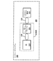
次に図6を参照すると、オリジネータ交換識別子構造、すなわちOX IDインデックス605及びレスポンダ交換識別子構造、すなわちRX IDインデックス610が示されている。RX IDインデックス610は、レスポンダに備えられ、所定数の交換識別子RX ID1〜Mを含んでいる。これらの総数は、レスポンダが処理できるオープン交換の数に制限される。RX IDインデックス610の部分、例えば、部分620は、RX IDの所定範囲で構成されており、本発明の技術思想に応じて、特定のオリジネータに、高速書き込みトランザクションを実行するために割り当てられている。参照番号621は、高速書き込みのために該オリジネータが使用する有効な第1のRX IDを表している。参照番号629は、同様に、該オリジネータに割り当てられている最後のRX IDを示している。図には示してないが、インデックス610の各RX IDは、レスポンダのリソース部分に関連していることが好ましい。
【0051】
OX IDインデックス605は、オリジネータに備えられており、所定数のOX ID1〜Mを含んでいる。これらのOX IDは、オリジネータが処理できるオープン交換の総数に制限されている。OX IDインデックス605の各OX IDは、オリジネータのリソース部分に関連していることが好ましい。さらに、OX IDインデックス605の部分615は、関連付マッピング650により、RX IDインデックスの部分620と関連付けられていることが好ましい。この機能は、部分620中の割り当てられたRX IDをマッピングするために、オリジネータに備えられる。なお、他の方法のマッピングを採用できることは言うまでもない。
【0052】
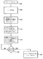
図7には、本発明の動作のフローチャートが示されている。上記したように、FCデバイスへログするプロセスは、まったくのシーケンシャルなタスクである。したがって、高速書き込み(FW)可能なレスポンダは、ログするオリジネータ(FW可能または不可能)が幾つFCチャネル仲裁ループに存在するのかが分かっていない。多数のオリジネータが存在する環境においては、すべてのFW可能なオリジネータが、FW可能でベンダ・コンパチブルなレスポンダのそれぞれによってオリジネータに割り当てられた適切な数のRX IDを保有することを、確実にする必要がある。
【0053】
図7のブロック701においてスタート/リセットが行われた後、ブロック702において、FCデバイスは、AL PAを環境設定するためにループ初期化を行う。次に、ブロック703において、オリジネータはログイン・プロセスを実行するが、FW可能デバイスのPLOGIフレームは、FW可能な特性をレスポンダに示すために埋め込まれた情報を含んでおり、該フレームをログインする。次にブロック710において、本発明の技術思想に係る高速書き込みが可能なレスポンダは、特定のFWオリジネータを排他的に使用するために、RX IDインデックスから所定数選択されたRX IDを割り当てる。このクリティカル(臨界的)情報は、レスポンダからオリジネータへ送信されるLS ACKフレームのベンダ特定部分に埋め込まれている。
FW可能なレスポンダからクリティカル情報を受信すると、オリジネータは、それらの使用をマッピングするために、レスポンダからの割り当てられたRX IDに、オリジネータのOX IDインデックス中の一部分を関連付ける。これは、ブロック715に示されている。
【0054】
レスポンダは、ループ初期化ステップ(ブロック702)を、ある条件に基づいて開始することが可能である。例えば、あるオリジネータが他のオリジネータの開始の前にコンパチブル・レスポンダにログインすると、該オリジネータは、高速書き込みをサポートするRX IDのすべてを割り当てられる。それから所定時間経過後に他のオリジネータがそのレスポンダにログインする場合には、返送されたLS ACKフレームは、FW可能なRX IDが利用不可能であることを表している。このような状態において、レスポンダは、仲裁ループにログインしている1又は複数のオリジネータが存在していることを検出する。レスポンダがこのような状態を検出すると、該レスポンダは、すべてのオリジネータが該レスポンダにログバックするよう、初期化ステップを開始することができる。レスポンダは幾つのオリジネータがループに存在するかについての知識を有しており、そのRX IDインデックスの部分を割り当てることが可能となる。
【0055】
更に図7を参照する。高速書き込みにしたがってコマンド及びデータ・フレームがレスポンダによって受信された後、オリジネータに、コマンドが完了したことを表すステータス・フレームが返送されたかどうか、判定ブロック720において、判定する。返送されている場合は、ブロック725において、高速書き込みコマンドに関して用いられたRX IDをリリース(開放)し、そして、該RX IDを将来使用するために再度の関連付けを行う。
本発明の技術思想に係るオリジネータがコマンド/データ・フレームよりも長いデータの書き込みを実行したい場合、または、オリジネータがその割り当てられたFW可能なRX ID以外のものに進んだ場合は、書き込みコマンドの発生をデフォルトして、通常のプロセスに戻るために転送レディ・フレームを待機するだけでよい。これと同一のデフォルト・オプションを、ベンダ特定のFW可能なオリジネータであって、異なるベンダからレスポンダへデータを転送したいオリジネータのために、備えることができる。
【0056】
当業者には、本発明により、ファイバ・チャネル環境において用いられている従来例のデータ転送技術の問題点を十分に解消できることが、明らかであろう。本発明によれば、受信側デバイスへのデータの書き込みを極めて効果的に実行できる。このような改善された機能により、多数のイニシエータが存在しかつループ・レイテンシが大きい大規模ループにおいて、顕著に特性が向上する。
以上の説明から、本発明により、FC環境において多数のイニシエータの制御および管理を行う画期的な機構を提供することによって、従来技術の問題を首尾良く解決することができることは、当業者に明らかであろう。本発明のいくつかの実施例のみを添付図面に示し前述の詳細な説明に記載したが、本発明は開示した実施例に限定される訳ではなく、特許請求の範囲に記載しそれによって規定される本発明の精神から逸脱することなく、多数の再構成、変更および交換が可能である。
【図面の簡単な説明】
【図1】本発明を実施可能な、コンピュータ・システムの一例を示すブロック図である。
【図2】ファイバ・チャネル(FC)プロトコル・スタックを示す模式図である。
【図3】ファイバ・チャネル・ノードに使用可能な3種類のトポロジ構成を示すブロック図である。
【図4】(A)は、ファイバ・チャネル環境において、イニシエータからターゲットへデータを転送するための、従来例の方式を説明するための図である。(B)は、ファイバ・チャネル環境において、イニシエータからターゲットへデータを転送するための、本発明の方式を説明するための図である。
【図5】本発明の技術思想に係る通信フレームの一部分を説明するための概念図である。
【図6】本発明の技術思想に係るファイバ・チャネル・デバイス用の交換識別子構造を説明するための概念図である。
【図7】本発明の技術思想に係る、オリジネータとレスポンダとの間でデータ書き込みを効果的に実行するためのプロセスを示すフローチャートである。[0001]
BACKGROUND OF THE INVENTION
The present invention relates to channel and network communication systems and communication methods, and more particularly to systems and methods that can improve write capability in a fiber channel (FC) environment.
[0002]
[Prior art]
There are two types of protocol for device communication: channel and network. Channels are designed to carry large amounts of data at very high speeds over relatively short distances with little software overhead once data communication has begun between the master host computer and slave peripheral devices. . Channels are typically hardware intensive and provide a direct or switched point-to-point connection between master and slave. A network, on the other hand, is designed to interface to many users sharing multiple hosts and system resources over medium to long distances and to support many transactions. For networks, as long as high connectivity is obtained, usually an increase in overhead is acceptable.
[0003]
The Fiber Channel Protocol (“FCP”) is a new stack architecture that combines the best of these two heterogeneous communication methods into a single open system interface (OSI) stack architecture. Generation protocol. In essence, Fiber Channel (“FC”) is a multi-topology multi-layer stack, a lower-layer protocol (“LLP”) that controls physical transport characteristics. protocol "), and upper-layer-protocols (" ULPs ") that map LLP communications between higher-level software structures compatible with the operating system. , Including both channel and network protocols, such as Intelligent Peripheral Interface (IPI), Small Computer System Interface (“SCSI”), and Internet Protocol (“IP” : Internet Protocol ”) It includes Le.
[0004]
It is well known that devices involved in either channel communication or network communication are classified as “initiators” or “targets” or both. Several specific functions are assigned to either the initiator or the target. That is, (i) the initiator can perform arbitration of the communication path and select a target. (Ii) The target can request the transfer of commands, data, status, or other information to or from the initiator. (Iii) In some cases, the target may arbitrate the communication path and reselect the initiator to continue the transaction.
[0005]
For devices that can operate with the Fiber Channel protocol, only devices that have an initiator function are known in the art as Link Service Requests or Extended Link Service Requests. Can start. The link service command gives the Fiber Channel initiator the ability to perform tasks such as node discovery, request abort, and communication frame rejection. The only link service command that a Fiber Channel target can initiate is command / frame rejection ("LS_RJT").
[0006]
In general, in a single initiator FC environment, the initiator device sends the required link service command and in response the link service acknowledgment (“LS_ACK”) frame or link sent from the target. Wait for reception of a service denial frame (LS_RJT). Hereinafter, these LS_ACK and LS_RJT frames will be collectively referred to as “response” frames or response frames. On the other hand, in a multi-initiator environment, the initiator operates as both a reception side and a transmission side of a link service command. Because of these dual roles, such an initiator operates as both a response frame receiver and sender.
[0007]
[Problems to be solved by the invention]
In the technical field of communication systems, effective data transfer at high speed is a very important factor. Further, such a transfer rate largely depends on the latency of the communication path, the total number of devices, and the presence of a large number of initiators. Today's FC-compatible systems typically include a single initiator, in which data is written separately by sending a command frame and a data frame from the sender to the receiver. By being continuously executed.
[0009]
Such continuous frame transfer may cause an inconvenient write state, particularly when the communication path is long and the latency period is increased. Thus, it will be apparent that there is a long-felt need to provide an efficient write mechanism in the FC environment.
Although there are a large number of single-initiator FC systems capable of continuous writing, an FC communication system that solves the above-described problems and has all the novel features and effects of the present invention described below is as follows. Not yet developed.
[0010]
[Means for Solving the Problems]
The present invention provides the following method and system in order to solve the above-mentioned problems and other problems as well as technical imperfections.
The method of the present invention is a method for transferring data from an originator to a responder in a Fiber Channel (FC) communication environment including at least one originator and at least one responder, wherein the write command is sent from the originator to the responder. And at least one data frame together, and a transmission step of transmitting a status frame from the responder to the originator when the transmission step is completed. .
In a preferred embodiment, the method further comprises a plurality of responder exchange identifiers (RX) Responder exchange identification (RX) associated with the responder Assigning a selected portion of the ID) index, which uniquely identifies the originator, and transmitting information related to the selected portion to the originator, the acknowledge from the responder (Acknowledgment confirmation) and a step of transmitting information by the payload portion of the frame.
[0011]
The present invention also provides a system for transferring data in a fiber channel (FC) communication environment, the system comprising an originator for transmitting data and a responder for receiving data, wherein the originator is a responder. Characterized by assigning selected portions of responder exchange identifiers for exclusive use of the originator according to the transfer of data so that commands and data frames can be sent together .
[0012]
DETAILED DESCRIPTION OF THE INVENTION
Reference will now be made to the drawings, in which like or similar elements are designated with the same reference numerals throughout the drawings. Further, the various elements are not necessarily drawn at the same scaling ratio.
FIG. 1 shows a block diagram of an
[0013]
Furthermore, OS 210 is operable with at least one conventional channel communication interface, such as the SCSI standard. The exemplary OS 210 may further be provided with a functional structure that allows interoperability with conventional network communication protocols, such as, for example, Internet Protocol (“IP”).
[0014]
With continued reference to FIG. 1, the
[0015]
Still referring to FIG. 1, it will be apparent that most operating systems, including, for example,
[0016]
Referring now to FIG. 2, a schematic diagram of an
[0017]
[0018]
[0019]
The
[0020]
Still referring to FIG. 2, the FC-2 layer is the main “workhorse” of the
[0021]
One important feature of the
[0022]
The FC-3 layer, ie,
[0023]
The
[0024]
Still referring to FIG. 2, various FC-4 level mappings are specified for a number of higher layer channels and network communication protocols. Among them are Intelligent Peripheral Interface (“IPI”), SCSI, High Performance Parallel Interface (“HIPPI”), Single Byte Command Code Set (“SBCCS”). , Logical link control ("LLC: Logical Link Control"), IP, and asynchronous transfer mode ("ATM: Asynchronous Transfer Mode") adaptation layer ("AAL: Adaptation Layer").
[0025]
Devices operable with the Fiber Channel protocol are controllers that embody some functions of the intermediate layers of the FCP stack 300 (hereinafter “FC controllers”), regardless of whether they are initiators or targets. Usually). For example, current FC controllers generally embody the functions of
[0026]
The central mechanism for coordinating the exchange of information between two FC devices is a process that can operate at the highest level in the FC architecture and is commonly referred to in this field as an exchange. An exchange consists of one or more related sequences, ie, one or more data frames that are transferred from one FC device to another. There are many exchanges between two FC devices, but usually only one sequence is active in the exchange. For exchange, the FC master device and stave device are usually called the originator and responder, respectively. With respect to the sequence, the master device and the slave device are called the initiator and the recipient, respectively.
[0027]
Frames that are characterized by various lengths generally have a start delimiter (start of frame (SOF) delimiter), a frame header, a payload, a cyclic redundancy check (CRC), and an end delimiter ( End of frame (EOF) delimiter). SOF and EOF include FC-specific special characters, which are used to represent the start and end points of the frame. The FC-specific special character is a 10-bit transmission character and does not have a corresponding 8-bit value (as described above, 8-bit / 10-bit block encoding), but is considered valid.
[0028]
The FC profile is an interoperable specification and is used industrially as a set of implementation guidelines for multiple FC-4 level ULP mappings. The profile is provided as a framework of rules for system manufacturing, system assembly, parts manufacturing, and user recruitment, so that interoperable FC peripheral elements, hosts, and elements can be designed and selected To do. Each profile specifies that the Fiber Channel physical, link level, and ULP option settings described above are to be selected for interoperable use. Basically, one FC profile can be considered as a virtual slice through the FC option space. Table 1 below schematically shows the contents of a frame header operable with the FC-SCSI profile.
[Table 1]
The many frame header fields in Table 1 are described below. R The CTL field identifies the frame as part of the FC protocol operation and identifies the category of information. D The ID field identifies the destination of the frame. D sent from the exchange originator The ID is a SCSI target identifier. S The ID field identifies the source of the frame, i.e. the frame source, and the S from the exchange originator. The ID is a SCSI standard initiator identifier. The type (TYPE) field identifies the protocol of the frame content for the data frame. For SCSI-FCP, the value of this field is 0x08.
[0030]
F in Table 1 The CTL field manages the start of sequence and exchange, and normal end or abnormal end. SEQ The ID identifies each sequence between a specific exchange originator and an exchange responder having a specific value. DF The CTL specifies an optional header that exists. These headers are not always necessary. SEQ The CET field represents the order of frames in the sequence. OX The ID field is the originator identifier of the exchange to uniquely identify the frame, and these frames form part of the particular exchange. RX The ID field is an exchange responder identifier for specifying a frame constituting a specific exchange part. As will be clear from the description below, RX in the frame from the originator The ID field is adopted according to the technical idea of the present invention, so that an effective write operation in which a command frame and a data frame are transmitted together can be executed.
[0031]
RLTV The OFF field represents the relative displacement of the first bit of each payload of the frame with respect to the base address of the information category. FC For the SCSI profile, the relative offset is the client buffer offset of the SCSI standard application, and the base address is the starting address of the client buffer of the application.
The originator typically handles a limited number of open exchanges. Each exchange provides resources in the originator, eg, memory portions, frames, frame headers, etc., thereby performing the exchange process with the selected responder. These resource parts are OX available to the originator It is preferably indexed by ID.
The responder can be handled in the same way, but only with the open exchange associated with the resource part in the responder. These resource parts are the RX available to the responder Indexed by ID. As will be apparent, each originator and responder can have multiple open exchanges.
[0032]
Next, referring to FIGS. 3A to 3C, three types of topology configuration examples are generally indicated by 490, 491, and 492, respectively, and FC nodes can be arranged therein. A node is an entity, system, or device that has the ability to handle some of the ULP, FC-3, and FC-2 functions. A node can include one or more ports, commonly known as node ports or N_PORTs. N_PORT is a hardware entity in a node that supports FC-PH. It can operate as a source (ie, initiator), responder (ie, target), or both. Hereinafter, the terms node, device, and port will be used interchangeably.
[0033]
490 in FIG. 3A indicates a point-to-point topology, and a full-duplex transmission path is established between any two FC nodes (in this case, indicated by
[0034]
A communication path, eg,
[0035]
Arbitrated
[0036]
As known in the art, only one pair of L_PORTs can be communicated at a time. If these L_PORTs relinquish control of the loop, a point-to-point connection between the other two L_PORTs can be established. Further, the entire loop can be alternately attached to the FC switched fabric port through what is known as FL_PORT or directly to a single host system through NL_PORT.
The presently preferred exemplary embodiment of the present invention includes an FC-AL topology, such as
[0037]
The FC-AL standard allows each FC device to negotiate an arbitrated loop physical address (AL_PA) in the loop initialization process, which is known. While participating in the arbitrated loop, the FC devices must log in to each other before initiating the loop transaction. The login procedure is an initial procedure that is executed by all communication nodes and establishes service parameters and a common operating environment. One example of a service parameter is a “credit” limit. This represents the maximum number of outstanding frames that the port can transmit without causing buffer storage overflow at the receiving port. It is obvious that credit is a flow control mechanism that restricts link traffic by limiting the number of frames that can be transmitted from each source port. Conventional FC controllers generally have two types of credits: buffer-to-buffer credit ("BB_Credit: buffer-to-buffer credit") and terminal (end) -to-terminal credit ("EE_Credit: end-to-end credit"). It is used.
[0038]
If a device does not log in to another device, it discards all frames received from that device until it logs in. Since the initiator or driver must be able to manage the target device with which it is communicating, the initiator keeps track of the FC-identity triplet for that target device. This FC specific ID triplet consists of the target node name, its port name, and its AL_PA. AL_PA is dynamically assigned at the time of loop reset, but the node name and port name are formed from the device's unique World Wide Name (World_Wide_Name).
[0039]
At reset, if the device goes up on the arbitrated loop, the device configures the device's AL_PA in one of three ways in the loop initialization step. In the Soft Address scheme, the device does not care what AL_PA is assigned to it. Rather, simply accept what is available in the first unused AL_PA. In the preferred address scheme, the FC device wants to be assigned a specific AL_PA. However, if for some reason the desired AL_PA is not available, accept any unused and available AL_PA. For example, after initializing the “overall” system following the OS load, the device continues to request that AL_PA upon subsequent loop resets after the device is initially assigned a specific AL_PA. However, once this device goes out of the arbitrated loop, the ability to “select” its AL_AP is lost and must be reluctant to accept the first available unused AL_PA.
[0040]
Third, in the hard address scheme, the FC device can only operate with a specific AL_PA. According to the loop initialization protocol (“LIP”) in the FC-AL standard that deals with the configuration of the AL_AP, this address configuration method is superior to the first two methods: the soft address method and the preferred address method. is there.
The initiator FC device can initiate a link service command / frame after all AL_PA allocation issues have been resolved. The link service frame includes both a “request” frame and a “response” frame. The request frame is a link service frame that requests the receiving device to send back a response frame. For example, a login link service frame (“PLLOGI: Login Link Service Frames”), a logout frame ( “PLOGO: Logout Frames”), N_Port Service Parameter Discovery Frame (“PDISC: Discover N_Port Service Parameters”), Address Discovery Frame (“ADISC: Discover Address Frames”), Process Login Frame (“PRLI: Process Login”). Frames ”), process logout frames (“ PRLO ”), and reinstate recovery qualifier frames (“ RRQ ”).
[0041]
In a single initiator environment, the initiator device sends out a link service frame as needed and expects an acknowledge frame (LS_ACC) or a reject frame (LS_RJT) in response. Furthermore, the initiator device stores the type information (hereinafter referred to as “type information element”) for each link service frame in a storage array called a pending link service array, and sends out the link. • Track the type of service frame. This pending link service array consists of a plurality of storage locations, each corresponding to the receiving device's AL_PA. Further, in an exemplary embodiment, all link service frame types are stored at each receiver as they are sent out.
[0042]
The initial port discovery process by the initiator device is a two-step process in the FC-AL environment, regardless of whether it contains one or more initiators. First, if the initiator has already logged into the receiving device, a PDISC frame is transmitted. In other cases, a PLOGI frame is transmitted. Second, when an LS_ACC frame is returned and received in response to a PLOGI frame, the initiator sends a PRLI frame to the responding side. On the other hand, when the LS_ACC frame is returned and received in response to the PDISC frame, it is not necessary to send another frame to the responding side.
[0043]
FIG. 4A shows a scheme of a conventional method for effectively transferring data from the
[0044]
Thereafter, by gaining loop control by arbitration, the
[0045]
Obviously, the prior art Fiber Channel write technique as described above requires at least four loop arbitrations to complete the write command and is therefore impractical. As is known in the art, loop arbitration is time consuming and as the total number of arbitrations per command execution cycle increases, so does system functionality. Furthermore, if the loop technology includes a large number of initiators, or if the loop distance increases due to the addition of a large number of devices, the write function will be degraded.
[0046]
FIG. 4B discloses a method for increasing the fiber channel function according to the technical idea of the present invention. The
[0047]
FIG. 5 shows a
[0048]
In FIG. 5, the target / responder device provided by the present invention uses a
[0049]
Still referring to FIG. The originator provided by the technical idea of the present invention uses at least the
[0050]
Referring now to FIG. 6, the originator exchange identifier structure, ie
[0051]
OX The
[0052]
FIG. 7 shows a flowchart of the operation of the present invention. As mentioned above, the process of logging to the FC device is a completely sequential task. Thus, a fast write (FW) capable responder does not know how many originators (FW capable or impossible) to log exist in the FC channel arbitration loop. In an environment with a large number of originators, all FW-capable originators have the appropriate number of RXs assigned to the originator by each of the FW-capable and vendor-compatible responders. It is necessary to ensure that the ID is held.
[0053]
After the start / reset is performed in
Upon receiving critical information from a FW capable responder, the originator can assign an assigned RX from the responder to map their use. OX of originator in ID Associate a portion of the ID index. This is indicated by
[0054]
The responder may initiate the loop initialization step (block 702) based on certain conditions. For example, if an originator logs into a compatible responder before the start of another originator, the originator will receive an RX that supports fast writes. All of the IDs are assigned. If another originator logs in to the responder after a certain period of time, the returned LS ACK frame is FW-capable RX This indicates that the ID cannot be used. In such a situation, the responder detects that there is one or more originators logged into the arbitration loop. When the responder detects such a condition, the responder can initiate an initialization step so that all originators log back to the responder. The responder has knowledge of how many originators are in the loop and its RX An ID index portion can be assigned.
[0055]
Still referring to FIG. After a command and data frame is received by the responder according to the fast write, a determination is made at
When the originator according to the technical idea of the present invention wants to execute writing of data longer than the command / data frame, or the originator has its assigned FW capable RX If you proceed to something other than ID, you only have to wait for the transfer ready frame to default to the generation of the write command and return to the normal process. This same default option can be provided for vendor specific FW capable originators who wish to transfer data from different vendors to responders.
[0056]
It will be apparent to those skilled in the art that the present invention can sufficiently overcome the problems of the prior art data transfer techniques used in fiber channel environments. According to the present invention, it is possible to execute data writing to the receiving device extremely effectively. Such an improved function significantly improves the characteristics in a large-scale loop having a large number of initiators and a large loop latency.
From the above description, it will be apparent to those skilled in the art that the present invention can successfully solve the problems of the prior art by providing an innovative mechanism for controlling and managing a large number of initiators in an FC environment. Will. While only certain embodiments of the invention have been illustrated in the accompanying drawings and described in the foregoing detailed description, the invention is not limited to the disclosed embodiments, but is described and defined by the claims. Numerous reconfigurations, modifications, and replacements are possible without departing from the spirit of the present invention.
[Brief description of the drawings]
FIG. 1 is a block diagram illustrating an example of a computer system in which the present invention can be implemented.
FIG. 2 is a schematic diagram illustrating a Fiber Channel (FC) protocol stack.
FIG. 3 is a block diagram showing three types of topology configurations that can be used for Fiber Channel nodes.
FIG. 4A is a diagram for explaining a conventional method for transferring data from an initiator to a target in a fiber channel environment; (B) is a diagram for explaining the method of the present invention for transferring data from an initiator to a target in a fiber channel environment.
FIG. 5 is a conceptual diagram for explaining a part of a communication frame according to the technical idea of the present invention.
FIG. 6 is a conceptual diagram for explaining an exchange identifier structure for a fiber channel device according to the technical idea of the present invention.
FIG. 7 is a flowchart showing a process for effectively executing data writing between an originator and a responder according to the technical idea of the present invention.
Claims (3)
ターゲットにおける複数のレスポンダ交換識別子の所定の部分を、2以上のイニシエータの排他的使用のために割り当てるステップと、
前記複数のレスポンダ交換識別子に関連する情報を、前記2以上のイニシエータに送信するステップと、
前記2以上のイニシエータから前記ターゲットに、コマンドと前記所定の部分に含まれる1つのレスポンダ交換識別子が付加されているデータ・フレームとを一緒に送るコマンド送信ステップと、
前記コマンド送信ステップの完了を示すステータス・フレームを、前記ターゲットから前記2以上のイニシエータに送信するステップと
からなることを特徴とする方法。In a method for improving write capability in a fiber channel arbitration loop,
Assigning a predetermined portion of a plurality of responder exchange identifiers at a target for exclusive use of two or more initiators;
Transmitting information related to the plurality of responder exchange identifiers to the two or more initiators;
A command transmission step of sending a command and a data frame to which one responder exchange identifier included in the predetermined part is added from the two or more initiators to the target;
Transmitting a status frame indicating completion of the command transmission step from the target to the two or more initiators.
Applications Claiming Priority (2)
| Application Number | Priority Date | Filing Date | Title |
|---|---|---|---|
| US828672 | 1992-01-31 | ||
| US08/828,672 US6356944B1 (en) | 1997-03-31 | 1997-03-31 | System and method for increasing write performance in a fibre channel environment |
Publications (2)
| Publication Number | Publication Date |
|---|---|
| JPH10303936A JPH10303936A (en) | 1998-11-13 |
| JP4068715B2 true JP4068715B2 (en) | 2008-03-26 |
Family
ID=25252433
Family Applications (1)
| Application Number | Title | Priority Date | Filing Date |
|---|---|---|---|
| JP08349798A Expired - Fee Related JP4068715B2 (en) | 1997-03-31 | 1998-03-30 | Data transfer system and method in fiber channel environment |
Country Status (4)
| Country | Link |
|---|---|
| US (1) | US6356944B1 (en) |
| EP (1) | EP0869642B1 (en) |
| JP (1) | JP4068715B2 (en) |
| DE (1) | DE69831827T2 (en) |
Families Citing this family (47)
| Publication number | Priority date | Publication date | Assignee | Title |
|---|---|---|---|---|
| US5978379A (en) | 1997-01-23 | 1999-11-02 | Gadzoox Networks, Inc. | Fiber channel learning bridge, learning half bridge, and protocol |
| US6185203B1 (en) * | 1997-02-18 | 2001-02-06 | Vixel Corporation | Fibre channel switching fabric |
| US6118776A (en) | 1997-02-18 | 2000-09-12 | Vixel Corporation | Methods and apparatus for fiber channel interconnection of private loop devices |
| US6643693B1 (en) * | 1998-09-15 | 2003-11-04 | Crossroads Systems, Inc. | Method and system for managing I/O transmissions in a fibre channel network after a break in communication |
| US6381647B1 (en) * | 1998-09-28 | 2002-04-30 | Raytheon Company | Method and system for scheduling network communication |
| US6888800B1 (en) * | 1998-11-14 | 2005-05-03 | Emulex Design & Manufacturing Corporation | High performance digital loop diagnostic technology |
| US7430171B2 (en) | 1998-11-19 | 2008-09-30 | Broadcom Corporation | Fibre channel arbitrated loop bufferless switch circuitry to increase bandwidth without significant increase in cost |
| US6499058B1 (en) * | 1999-09-09 | 2002-12-24 | Motokazu Hozumi | File shared apparatus and its method file processing apparatus and its method recording medium in which file shared program is recorded and recording medium in which file processing program is recorded |
| US6609165B1 (en) * | 1999-09-27 | 2003-08-19 | International Business Machines Corporation | Method and apparatus for using fibre channel extended link service commands in a point-to-point configuration |
| US6526458B1 (en) * | 1999-12-30 | 2003-02-25 | Agilent Technologies, Inc. | Method and system for efficient i/o operation completion in a fibre channel node using an application specific integration circuit and determining i/o operation completion status within interface controller |
| US7401139B1 (en) * | 2000-09-07 | 2008-07-15 | International Business Machines Corporation | Storage area network management and configuration method and apparatus via enabling in-band communications |
| US7212534B2 (en) | 2001-07-23 | 2007-05-01 | Broadcom Corporation | Flow based congestion control |
| GB0119070D0 (en) * | 2001-08-06 | 2001-09-26 | Ibm | Method and apparatus for managing a loop network |
| US7047346B2 (en) * | 2001-12-31 | 2006-05-16 | Storage Technology Corporation | Transparent fiber channel concentrator for point to point technologies |
| US8244890B2 (en) * | 2002-03-08 | 2012-08-14 | Broadcom Corporation | System and method for handling transport protocol segments |
| US7295555B2 (en) | 2002-03-08 | 2007-11-13 | Broadcom Corporation | System and method for identifying upper layer protocol message boundaries |
| US8051197B2 (en) * | 2002-03-29 | 2011-11-01 | Brocade Communications Systems, Inc. | Network congestion management systems and methods |
| US20040076428A1 (en) * | 2002-05-20 | 2004-04-22 | The Boeing Company | Form existing fibers into a fibre channel-arbitrated loop |
| US7934021B2 (en) | 2002-08-29 | 2011-04-26 | Broadcom Corporation | System and method for network interfacing |
| US7346701B2 (en) | 2002-08-30 | 2008-03-18 | Broadcom Corporation | System and method for TCP offload |
| US8180928B2 (en) | 2002-08-30 | 2012-05-15 | Broadcom Corporation | Method and system for supporting read operations with CRC for iSCSI and iSCSI chimney |
| WO2004021626A2 (en) | 2002-08-30 | 2004-03-11 | Broadcom Corporation | System and method for handling out-of-order frames |
| US7313623B2 (en) | 2002-08-30 | 2007-12-25 | Broadcom Corporation | System and method for TCP/IP offload independent of bandwidth delay product |
| US7689708B1 (en) * | 2002-10-28 | 2010-03-30 | Netapp, Inc. | Apparatus to flow control frames in a networked storage virtualization using multiple streaming protocols |
| US7145877B2 (en) * | 2003-03-31 | 2006-12-05 | Cisco Technology, Inc. | Apparatus and method for distance extension of fibre-channel over transport |
| KR100578080B1 (en) * | 2003-11-14 | 2006-05-10 | 엘지전자 주식회사 | Sending and Receiving Method of Command and Data in Serial Transmission Protocol |
| US7907626B2 (en) * | 2004-08-12 | 2011-03-15 | Broadcom Corporation | Method and system to allocate exchange identifications for Fibre Channel N-Port aggregation |
| US7672323B2 (en) * | 2005-01-14 | 2010-03-02 | Cisco Technology, Inc. | Dynamic and intelligent buffer management for SAN extension |
| US7373444B2 (en) * | 2005-04-15 | 2008-05-13 | Kabushiki Kaisha Toshiba | Systems and methods for manipulating entries in a command buffer using tag information |
| US8176217B2 (en) * | 2005-12-20 | 2012-05-08 | Lsi Corporation | System and method for implementing a storage protocol with initiator controlled data transfer |
| JP4354492B2 (en) * | 2007-01-31 | 2009-10-28 | 富士通株式会社 | Disk drive diagnostic device |
| JP2009182458A (en) * | 2008-01-29 | 2009-08-13 | Sony Corp | Communication apparatus, communication system, communication method, and program |
| US7853726B2 (en) * | 2008-10-06 | 2010-12-14 | International Business Machines Corporation | FCP command-data matching for write operations |
| US8909864B2 (en) | 2011-09-30 | 2014-12-09 | Hewlett-Packard Development Company, L.P. | Multicast write commands |
| US9769074B2 (en) | 2013-03-15 | 2017-09-19 | International Business Machines Corporation | Network per-flow rate limiting |
| US9118984B2 (en) | 2013-03-15 | 2015-08-25 | International Business Machines Corporation | Control plane for integrated switch wavelength division multiplexing |
| US9596192B2 (en) | 2013-03-15 | 2017-03-14 | International Business Machines Corporation | Reliable link layer for control links between network controllers and switches |
| US9609086B2 (en) | 2013-03-15 | 2017-03-28 | International Business Machines Corporation | Virtual machine mobility using OpenFlow |
| US9407560B2 (en) | 2013-03-15 | 2016-08-02 | International Business Machines Corporation | Software defined network-based load balancing for physical and virtual networks |
| US9104643B2 (en) | 2013-03-15 | 2015-08-11 | International Business Machines Corporation | OpenFlow controller master-slave initialization protocol |
| US9444748B2 (en) | 2013-03-15 | 2016-09-13 | International Business Machines Corporation | Scalable flow and congestion control with OpenFlow |
| US9864716B2 (en) | 2015-05-20 | 2018-01-09 | International Business Machines Corporation | Receiving buffer credits by a plurality of channels of one or more host computational devices for transmitting data to a control unit |
| US10061734B2 (en) | 2015-05-20 | 2018-08-28 | International Business Machines Corporation | Adjustment of buffer credits and other parameters in a startup phase of communications between a plurality of channels and a control unit |
| US9892065B2 (en) | 2015-05-20 | 2018-02-13 | International Business Machines Corporation | Adjustments of buffer credits for optimizing the number of retry operations and transfer ready operations |
| US11954220B2 (en) | 2018-05-21 | 2024-04-09 | Pure Storage, Inc. | Data protection for container storage |
| US10310760B1 (en) | 2018-05-21 | 2019-06-04 | Pure Storage, Inc. | Layering communication fabric protocols |
| US10693810B1 (en) * | 2018-12-12 | 2020-06-23 | Wipro Limited | Method and system for managing input output per second (IOPS) in fiber channel network topology |
Family Cites Families (8)
| Publication number | Priority date | Publication date | Assignee | Title |
|---|---|---|---|---|
| US5638518A (en) * | 1994-10-24 | 1997-06-10 | Lsi Logic Corporation | Node loop core for implementing transmission protocol in fibre channel |
| CA2221797C (en) * | 1995-05-26 | 2000-08-22 | Emulex Corporation | Linked caches for context data search |
| CA2186795A1 (en) * | 1995-11-17 | 1997-05-18 | Cormac John Sreenan | Resource management system for a broadband multipoint bridge |
| US5768530A (en) * | 1995-12-28 | 1998-06-16 | Emc Corporation | High speed integrated circuit interface for fibre channel communications |
| US5954796A (en) * | 1997-02-11 | 1999-09-21 | Compaq Computer Corporation | System and method for automatically and dynamically changing an address associated with a device disposed in a fire channel environment |
| US6014383A (en) * | 1997-02-10 | 2000-01-11 | Compaq Computer Corporation | System and method for controlling multiple initiators in a fibre channel environment |
| US5944798A (en) * | 1997-02-19 | 1999-08-31 | Compaq Computer Corp. | System and method for arbitrated loop recovery |
| US5956723A (en) * | 1997-03-21 | 1999-09-21 | Lsi Logic Corporation | Maintaining identifier information in a memory using unique identifiers as a linked list |
-
1997
- 1997-03-31 US US08/828,672 patent/US6356944B1/en not_active Expired - Fee Related
-
1998
- 1998-03-24 EP EP98302229A patent/EP0869642B1/en not_active Expired - Lifetime
- 1998-03-24 DE DE69831827T patent/DE69831827T2/en not_active Expired - Lifetime
- 1998-03-30 JP JP08349798A patent/JP4068715B2/en not_active Expired - Fee Related
Also Published As
| Publication number | Publication date |
|---|---|
| EP0869642A3 (en) | 1999-11-24 |
| EP0869642A2 (en) | 1998-10-07 |
| JPH10303936A (en) | 1998-11-13 |
| EP0869642B1 (en) | 2005-10-12 |
| DE69831827T2 (en) | 2006-05-11 |
| US6356944B1 (en) | 2002-03-12 |
| DE69831827D1 (en) | 2006-02-23 |
Similar Documents
| Publication | Publication Date | Title |
|---|---|---|
| JP4068715B2 (en) | Data transfer system and method in fiber channel environment | |
| US6014383A (en) | System and method for controlling multiple initiators in a fibre channel environment | |
| US5944798A (en) | System and method for arbitrated loop recovery | |
| US5954796A (en) | System and method for automatically and dynamically changing an address associated with a device disposed in a fire channel environment | |
| US8108454B2 (en) | Address assignment in Fibre Channel over Ethernet environments | |
| JP2699991B2 (en) | Data frame transmission method | |
| JP5068055B2 (en) | Data processing system, address assignment method and computer program (obtaining multiple port addresses from the network fabric with Fiber Channel switches) | |
| JP4335009B2 (en) | Method and apparatus for encapsulating frames for transmission within a storage area network | |
| US7720064B1 (en) | Method and system for processing network and storage data | |
| EP2406922B1 (en) | Providing fibre channel services and forwarding fibre channel over ethernet frames | |
| US8520686B2 (en) | Method for interfacing a fibre channel network with an ethernet based network | |
| US7340167B2 (en) | Fibre channel transparent switch for mixed switch fabrics | |
| US8018936B2 (en) | Inter-fabric routing | |
| EP2272217B1 (en) | Network system with initiator subnetwork communication | |
| US9219683B2 (en) | Unified infrastructure over ethernet | |
| US8351442B1 (en) | Method and system for network communication | |
| Ocheltree et al. | A comparison of fibre channel and 802 MAC services | |
| Rickard | Fibre channel as a network backbone | |
| US8225004B1 (en) | Method and system for processing network and storage data | |
| Munson | Introduction To Fibre Channel Connectivity. | |
| Guendert | Fibre Channel Standard | |
| Manual | Fibre Channel Interface | |
| Affeldt et al. | SCSI, Fibre Channel, and SANs | |
| JP2001223723A (en) | Ethernet (registered trademark) connection controller |
Legal Events
| Date | Code | Title | Description |
|---|---|---|---|
| A521 | Request for written amendment filed |
Free format text: JAPANESE INTERMEDIATE CODE: A523 Effective date: 20050119 |
|
| A621 | Written request for application examination |
Free format text: JAPANESE INTERMEDIATE CODE: A621 Effective date: 20050119 |
|
| TRDD | Decision of grant or rejection written | ||
| A01 | Written decision to grant a patent or to grant a registration (utility model) |
Free format text: JAPANESE INTERMEDIATE CODE: A01 Effective date: 20071213 |
|
| A61 | First payment of annual fees (during grant procedure) |
Free format text: JAPANESE INTERMEDIATE CODE: A61 Effective date: 20080111 |
|
| FPAY | Renewal fee payment (event date is renewal date of database) |
Free format text: PAYMENT UNTIL: 20110118 Year of fee payment: 3 |
|
| R150 | Certificate of patent or registration of utility model |
Free format text: JAPANESE INTERMEDIATE CODE: R150 |
|
| FPAY | Renewal fee payment (event date is renewal date of database) |
Free format text: PAYMENT UNTIL: 20120118 Year of fee payment: 4 |
|
| FPAY | Renewal fee payment (event date is renewal date of database) |
Free format text: PAYMENT UNTIL: 20130118 Year of fee payment: 5 |
|
| LAPS | Cancellation because of no payment of annual fees |