JP4065371B2 - Tissue fixation device and method - Google Patents
Tissue fixation device and method Download PDFInfo
- Publication number
- JP4065371B2 JP4065371B2 JP2000528214A JP2000528214A JP4065371B2 JP 4065371 B2 JP4065371 B2 JP 4065371B2 JP 2000528214 A JP2000528214 A JP 2000528214A JP 2000528214 A JP2000528214 A JP 2000528214A JP 4065371 B2 JP4065371 B2 JP 4065371B2
- Authority
- JP
- Japan
- Prior art keywords
- fixture
- flexible member
- distal end
- proximal end
- cable
- Prior art date
- Legal status (The legal status is an assumption and is not a legal conclusion. Google has not performed a legal analysis and makes no representation as to the accuracy of the status listed.)
- Expired - Lifetime
Links
Images


Classifications
-
- A—HUMAN NECESSITIES
- A61—MEDICAL OR VETERINARY SCIENCE; HYGIENE
- A61B—DIAGNOSIS; SURGERY; IDENTIFICATION
- A61B17/00—Surgical instruments, devices or methods, e.g. tourniquets
- A61B17/56—Surgical instruments or methods for treatment of bones or joints; Devices specially adapted therefor
- A61B17/58—Surgical instruments or methods for treatment of bones or joints; Devices specially adapted therefor for osteosynthesis, e.g. bone plates, screws, setting implements or the like
- A61B17/88—Osteosynthesis instruments; Methods or means for implanting or extracting internal or external fixation devices
- A61B17/8869—Tensioning devices
-
- A—HUMAN NECESSITIES
- A61—MEDICAL OR VETERINARY SCIENCE; HYGIENE
- A61B—DIAGNOSIS; SURGERY; IDENTIFICATION
- A61B17/00—Surgical instruments, devices or methods, e.g. tourniquets
- A61B17/04—Surgical instruments, devices or methods, e.g. tourniquets for suturing wounds; Holders or packages for needles or suture materials
- A61B17/0401—Suture anchors, buttons or pledgets, i.e. means for attaching sutures to bone, cartilage or soft tissue; Instruments for applying or removing suture anchors
-
- A—HUMAN NECESSITIES
- A61—MEDICAL OR VETERINARY SCIENCE; HYGIENE
- A61B—DIAGNOSIS; SURGERY; IDENTIFICATION
- A61B17/00—Surgical instruments, devices or methods, e.g. tourniquets
- A61B17/56—Surgical instruments or methods for treatment of bones or joints; Devices specially adapted therefor
- A61B17/58—Surgical instruments or methods for treatment of bones or joints; Devices specially adapted therefor for osteosynthesis, e.g. bone plates, screws, setting implements or the like
- A61B17/68—Internal fixation devices, including fasteners and spinal fixators, even if a part thereof projects from the skin
- A61B17/683—Internal fixation devices, including fasteners and spinal fixators, even if a part thereof projects from the skin comprising bone transfixation elements, e.g. bolt with a distal cooperating element such as a nut
-
- A—HUMAN NECESSITIES
- A61—MEDICAL OR VETERINARY SCIENCE; HYGIENE
- A61B—DIAGNOSIS; SURGERY; IDENTIFICATION
- A61B17/00—Surgical instruments, devices or methods, e.g. tourniquets
- A61B17/56—Surgical instruments or methods for treatment of bones or joints; Devices specially adapted therefor
- A61B17/58—Surgical instruments or methods for treatment of bones or joints; Devices specially adapted therefor for osteosynthesis, e.g. bone plates, screws, setting implements or the like
- A61B17/68—Internal fixation devices, including fasteners and spinal fixators, even if a part thereof projects from the skin
- A61B17/82—Internal fixation devices, including fasteners and spinal fixators, even if a part thereof projects from the skin for bone cerclage
-
- A—HUMAN NECESSITIES
- A61—MEDICAL OR VETERINARY SCIENCE; HYGIENE
- A61F—FILTERS IMPLANTABLE INTO BLOOD VESSELS; PROSTHESES; DEVICES PROVIDING PATENCY TO, OR PREVENTING COLLAPSING OF, TUBULAR STRUCTURES OF THE BODY, e.g. STENTS; ORTHOPAEDIC, NURSING OR CONTRACEPTIVE DEVICES; FOMENTATION; TREATMENT OR PROTECTION OF EYES OR EARS; BANDAGES, DRESSINGS OR ABSORBENT PADS; FIRST-AID KITS
- A61F2/00—Filters implantable into blood vessels; Prostheses, i.e. artificial substitutes or replacements for parts of the body; Appliances for connecting them with the body; Devices providing patency to, or preventing collapsing of, tubular structures of the body, e.g. stents
- A61F2/02—Prostheses implantable into the body
- A61F2/08—Muscles; Tendons; Ligaments
- A61F2/0805—Implements for inserting tendons or ligaments
-
- A—HUMAN NECESSITIES
- A61—MEDICAL OR VETERINARY SCIENCE; HYGIENE
- A61F—FILTERS IMPLANTABLE INTO BLOOD VESSELS; PROSTHESES; DEVICES PROVIDING PATENCY TO, OR PREVENTING COLLAPSING OF, TUBULAR STRUCTURES OF THE BODY, e.g. STENTS; ORTHOPAEDIC, NURSING OR CONTRACEPTIVE DEVICES; FOMENTATION; TREATMENT OR PROTECTION OF EYES OR EARS; BANDAGES, DRESSINGS OR ABSORBENT PADS; FIRST-AID KITS
- A61F2/00—Filters implantable into blood vessels; Prostheses, i.e. artificial substitutes or replacements for parts of the body; Appliances for connecting them with the body; Devices providing patency to, or preventing collapsing of, tubular structures of the body, e.g. stents
- A61F2/02—Prostheses implantable into the body
- A61F2/08—Muscles; Tendons; Ligaments
- A61F2/0811—Fixation devices for tendons or ligaments
-
- A—HUMAN NECESSITIES
- A61—MEDICAL OR VETERINARY SCIENCE; HYGIENE
- A61B—DIAGNOSIS; SURGERY; IDENTIFICATION
- A61B17/00—Surgical instruments, devices or methods, e.g. tourniquets
- A61B17/56—Surgical instruments or methods for treatment of bones or joints; Devices specially adapted therefor
- A61B17/58—Surgical instruments or methods for treatment of bones or joints; Devices specially adapted therefor for osteosynthesis, e.g. bone plates, screws, setting implements or the like
- A61B17/88—Osteosynthesis instruments; Methods or means for implanting or extracting internal or external fixation devices
- A61B17/8863—Apparatus for shaping or cutting osteosynthesis equipment by medical personnel
-
- A—HUMAN NECESSITIES
- A61—MEDICAL OR VETERINARY SCIENCE; HYGIENE
- A61B—DIAGNOSIS; SURGERY; IDENTIFICATION
- A61B17/00—Surgical instruments, devices or methods, e.g. tourniquets
- A61B17/04—Surgical instruments, devices or methods, e.g. tourniquets for suturing wounds; Holders or packages for needles or suture materials
- A61B17/0401—Suture anchors, buttons or pledgets, i.e. means for attaching sutures to bone, cartilage or soft tissue; Instruments for applying or removing suture anchors
- A61B2017/0409—Instruments for applying suture anchors
-
- A—HUMAN NECESSITIES
- A61—MEDICAL OR VETERINARY SCIENCE; HYGIENE
- A61B—DIAGNOSIS; SURGERY; IDENTIFICATION
- A61B17/00—Surgical instruments, devices or methods, e.g. tourniquets
- A61B17/04—Surgical instruments, devices or methods, e.g. tourniquets for suturing wounds; Holders or packages for needles or suture materials
- A61B17/0401—Suture anchors, buttons or pledgets, i.e. means for attaching sutures to bone, cartilage or soft tissue; Instruments for applying or removing suture anchors
- A61B2017/0417—T-fasteners
-
- A—HUMAN NECESSITIES
- A61—MEDICAL OR VETERINARY SCIENCE; HYGIENE
- A61B—DIAGNOSIS; SURGERY; IDENTIFICATION
- A61B17/00—Surgical instruments, devices or methods, e.g. tourniquets
- A61B17/04—Surgical instruments, devices or methods, e.g. tourniquets for suturing wounds; Holders or packages for needles or suture materials
- A61B17/0401—Suture anchors, buttons or pledgets, i.e. means for attaching sutures to bone, cartilage or soft tissue; Instruments for applying or removing suture anchors
- A61B2017/0446—Means for attaching and blocking the suture in the suture anchor
- A61B2017/0454—Means for attaching and blocking the suture in the suture anchor the anchor being crimped or clamped on the suture
-
- A—HUMAN NECESSITIES
- A61—MEDICAL OR VETERINARY SCIENCE; HYGIENE
- A61B—DIAGNOSIS; SURGERY; IDENTIFICATION
- A61B17/00—Surgical instruments, devices or methods, e.g. tourniquets
- A61B17/04—Surgical instruments, devices or methods, e.g. tourniquets for suturing wounds; Holders or packages for needles or suture materials
- A61B17/0401—Suture anchors, buttons or pledgets, i.e. means for attaching sutures to bone, cartilage or soft tissue; Instruments for applying or removing suture anchors
- A61B2017/0446—Means for attaching and blocking the suture in the suture anchor
- A61B2017/0458—Longitudinal through hole, e.g. suture blocked by a distal suture knot
-
- A—HUMAN NECESSITIES
- A61—MEDICAL OR VETERINARY SCIENCE; HYGIENE
- A61F—FILTERS IMPLANTABLE INTO BLOOD VESSELS; PROSTHESES; DEVICES PROVIDING PATENCY TO, OR PREVENTING COLLAPSING OF, TUBULAR STRUCTURES OF THE BODY, e.g. STENTS; ORTHOPAEDIC, NURSING OR CONTRACEPTIVE DEVICES; FOMENTATION; TREATMENT OR PROTECTION OF EYES OR EARS; BANDAGES, DRESSINGS OR ABSORBENT PADS; FIRST-AID KITS
- A61F2/00—Filters implantable into blood vessels; Prostheses, i.e. artificial substitutes or replacements for parts of the body; Appliances for connecting them with the body; Devices providing patency to, or preventing collapsing of, tubular structures of the body, e.g. stents
- A61F2/02—Prostheses implantable into the body
- A61F2/08—Muscles; Tendons; Ligaments
- A61F2/0811—Fixation devices for tendons or ligaments
- A61F2002/0817—Structure of the anchor
- A61F2002/0823—Modular anchors comprising a plurality of separate parts
- A61F2002/0829—Modular anchors comprising a plurality of separate parts without deformation of anchor parts, e.g. fixation screws on bone surface, extending barbs, cams, butterflies, spring-loaded pins
-
- A—HUMAN NECESSITIES
- A61—MEDICAL OR VETERINARY SCIENCE; HYGIENE
- A61F—FILTERS IMPLANTABLE INTO BLOOD VESSELS; PROSTHESES; DEVICES PROVIDING PATENCY TO, OR PREVENTING COLLAPSING OF, TUBULAR STRUCTURES OF THE BODY, e.g. STENTS; ORTHOPAEDIC, NURSING OR CONTRACEPTIVE DEVICES; FOMENTATION; TREATMENT OR PROTECTION OF EYES OR EARS; BANDAGES, DRESSINGS OR ABSORBENT PADS; FIRST-AID KITS
- A61F2/00—Filters implantable into blood vessels; Prostheses, i.e. artificial substitutes or replacements for parts of the body; Appliances for connecting them with the body; Devices providing patency to, or preventing collapsing of, tubular structures of the body, e.g. stents
- A61F2/02—Prostheses implantable into the body
- A61F2/08—Muscles; Tendons; Ligaments
- A61F2/0811—Fixation devices for tendons or ligaments
- A61F2002/0847—Mode of fixation of anchor to tendon or ligament
- A61F2002/0852—Fixation of a loop or U-turn, e.g. eyelets, anchor having multiple holes
-
- A—HUMAN NECESSITIES
- A61—MEDICAL OR VETERINARY SCIENCE; HYGIENE
- A61F—FILTERS IMPLANTABLE INTO BLOOD VESSELS; PROSTHESES; DEVICES PROVIDING PATENCY TO, OR PREVENTING COLLAPSING OF, TUBULAR STRUCTURES OF THE BODY, e.g. STENTS; ORTHOPAEDIC, NURSING OR CONTRACEPTIVE DEVICES; FOMENTATION; TREATMENT OR PROTECTION OF EYES OR EARS; BANDAGES, DRESSINGS OR ABSORBENT PADS; FIRST-AID KITS
- A61F2/00—Filters implantable into blood vessels; Prostheses, i.e. artificial substitutes or replacements for parts of the body; Appliances for connecting them with the body; Devices providing patency to, or preventing collapsing of, tubular structures of the body, e.g. stents
- A61F2/02—Prostheses implantable into the body
- A61F2/08—Muscles; Tendons; Ligaments
- A61F2/0811—Fixation devices for tendons or ligaments
- A61F2002/0847—Mode of fixation of anchor to tendon or ligament
- A61F2002/0858—Fixation of tendon or ligament between anchor and bone, e.g. interference screws, wedges
-
- A—HUMAN NECESSITIES
- A61—MEDICAL OR VETERINARY SCIENCE; HYGIENE
- A61F—FILTERS IMPLANTABLE INTO BLOOD VESSELS; PROSTHESES; DEVICES PROVIDING PATENCY TO, OR PREVENTING COLLAPSING OF, TUBULAR STRUCTURES OF THE BODY, e.g. STENTS; ORTHOPAEDIC, NURSING OR CONTRACEPTIVE DEVICES; FOMENTATION; TREATMENT OR PROTECTION OF EYES OR EARS; BANDAGES, DRESSINGS OR ABSORBENT PADS; FIRST-AID KITS
- A61F2/00—Filters implantable into blood vessels; Prostheses, i.e. artificial substitutes or replacements for parts of the body; Appliances for connecting them with the body; Devices providing patency to, or preventing collapsing of, tubular structures of the body, e.g. stents
- A61F2/02—Prostheses implantable into the body
- A61F2/08—Muscles; Tendons; Ligaments
- A61F2/0811—Fixation devices for tendons or ligaments
- A61F2002/0847—Mode of fixation of anchor to tendon or ligament
- A61F2002/0864—Fixation of tendon or ligament between anchor elements, e.g. by additional screws in the anchor, anchor crimped around tendon
-
- A—HUMAN NECESSITIES
- A61—MEDICAL OR VETERINARY SCIENCE; HYGIENE
- A61F—FILTERS IMPLANTABLE INTO BLOOD VESSELS; PROSTHESES; DEVICES PROVIDING PATENCY TO, OR PREVENTING COLLAPSING OF, TUBULAR STRUCTURES OF THE BODY, e.g. STENTS; ORTHOPAEDIC, NURSING OR CONTRACEPTIVE DEVICES; FOMENTATION; TREATMENT OR PROTECTION OF EYES OR EARS; BANDAGES, DRESSINGS OR ABSORBENT PADS; FIRST-AID KITS
- A61F2/00—Filters implantable into blood vessels; Prostheses, i.e. artificial substitutes or replacements for parts of the body; Appliances for connecting them with the body; Devices providing patency to, or preventing collapsing of, tubular structures of the body, e.g. stents
- A61F2/02—Prostheses implantable into the body
- A61F2/08—Muscles; Tendons; Ligaments
- A61F2/0811—Fixation devices for tendons or ligaments
- A61F2002/0847—Mode of fixation of anchor to tendon or ligament
- A61F2002/087—Anchor integrated into tendons, e.g. bone blocks, integrated rings
-
- A—HUMAN NECESSITIES
- A61—MEDICAL OR VETERINARY SCIENCE; HYGIENE
- A61F—FILTERS IMPLANTABLE INTO BLOOD VESSELS; PROSTHESES; DEVICES PROVIDING PATENCY TO, OR PREVENTING COLLAPSING OF, TUBULAR STRUCTURES OF THE BODY, e.g. STENTS; ORTHOPAEDIC, NURSING OR CONTRACEPTIVE DEVICES; FOMENTATION; TREATMENT OR PROTECTION OF EYES OR EARS; BANDAGES, DRESSINGS OR ABSORBENT PADS; FIRST-AID KITS
- A61F2/00—Filters implantable into blood vessels; Prostheses, i.e. artificial substitutes or replacements for parts of the body; Appliances for connecting them with the body; Devices providing patency to, or preventing collapsing of, tubular structures of the body, e.g. stents
- A61F2/02—Prostheses implantable into the body
- A61F2/08—Muscles; Tendons; Ligaments
- A61F2/0811—Fixation devices for tendons or ligaments
- A61F2002/0876—Position of anchor in respect to the bone
- A61F2002/0882—Anchor in or on top of a bone tunnel, i.e. a hole running through the entire bone
-
- A—HUMAN NECESSITIES
- A61—MEDICAL OR VETERINARY SCIENCE; HYGIENE
- A61F—FILTERS IMPLANTABLE INTO BLOOD VESSELS; PROSTHESES; DEVICES PROVIDING PATENCY TO, OR PREVENTING COLLAPSING OF, TUBULAR STRUCTURES OF THE BODY, e.g. STENTS; ORTHOPAEDIC, NURSING OR CONTRACEPTIVE DEVICES; FOMENTATION; TREATMENT OR PROTECTION OF EYES OR EARS; BANDAGES, DRESSINGS OR ABSORBENT PADS; FIRST-AID KITS
- A61F2/00—Filters implantable into blood vessels; Prostheses, i.e. artificial substitutes or replacements for parts of the body; Appliances for connecting them with the body; Devices providing patency to, or preventing collapsing of, tubular structures of the body, e.g. stents
- A61F2/02—Prostheses implantable into the body
- A61F2/08—Muscles; Tendons; Ligaments
- A61F2/0811—Fixation devices for tendons or ligaments
- A61F2002/0876—Position of anchor in respect to the bone
- A61F2002/0888—Anchor in or on a blind hole or on the bone surface without formation of a tunnel
-
- Y—GENERAL TAGGING OF NEW TECHNOLOGICAL DEVELOPMENTS; GENERAL TAGGING OF CROSS-SECTIONAL TECHNOLOGIES SPANNING OVER SEVERAL SECTIONS OF THE IPC; TECHNICAL SUBJECTS COVERED BY FORMER USPC CROSS-REFERENCE ART COLLECTIONS [XRACs] AND DIGESTS
- Y10—TECHNICAL SUBJECTS COVERED BY FORMER USPC
- Y10T—TECHNICAL SUBJECTS COVERED BY FORMER US CLASSIFICATION
- Y10T29/00—Metal working
- Y10T29/53—Means to assemble or disassemble
- Y10T29/53909—Means comprising hand manipulatable tool
- Y10T29/53943—Hand gripper for direct push or pull
- Y10T29/53952—Tube sleeve or ferrule applying or removing
-
- Y—GENERAL TAGGING OF NEW TECHNOLOGICAL DEVELOPMENTS; GENERAL TAGGING OF CROSS-SECTIONAL TECHNOLOGIES SPANNING OVER SEVERAL SECTIONS OF THE IPC; TECHNICAL SUBJECTS COVERED BY FORMER USPC CROSS-REFERENCE ART COLLECTIONS [XRACs] AND DIGESTS
- Y10—TECHNICAL SUBJECTS COVERED BY FORMER USPC
- Y10T—TECHNICAL SUBJECTS COVERED BY FORMER US CLASSIFICATION
- Y10T29/00—Metal working
- Y10T29/53—Means to assemble or disassemble
- Y10T29/53987—Tube, sleeve or ferrule
Landscapes
- Health & Medical Sciences (AREA)
- Life Sciences & Earth Sciences (AREA)
- Orthopedic Medicine & Surgery (AREA)
- Surgery (AREA)
- Animal Behavior & Ethology (AREA)
- General Health & Medical Sciences (AREA)
- Biomedical Technology (AREA)
- Heart & Thoracic Surgery (AREA)
- Veterinary Medicine (AREA)
- Engineering & Computer Science (AREA)
- Public Health (AREA)
- Molecular Biology (AREA)
- Nuclear Medicine, Radiotherapy & Molecular Imaging (AREA)
- Medical Informatics (AREA)
- Rheumatology (AREA)
- Rehabilitation Therapy (AREA)
- Cardiology (AREA)
- Oral & Maxillofacial Surgery (AREA)
- Transplantation (AREA)
- Vascular Medicine (AREA)
- Neurology (AREA)
- Surgical Instruments (AREA)
Description
【0001】
(発明の背景)
本発明は、外科用器具及び方法に関し、より特定すると、骨及び軟質組織の修復のための器具及び方法に関する。
【0002】
骨片、二以上の骨又は軟質組織と骨との結合のような二以上の部片を相互に固定することは、整形外科手術における一般的な要件である。この固定は、二片の骨を貫通し且つ部片を一体化させるためにナットを使用する骨用ボルト、骨用ねじと連結プレート、少なくとも二つの骨片を取り巻くワイヤ、又は組織内への縫い付けのような多数の器具によって達成されて来た。
【0003】
このような器具は、固定具を埋め込むために、包囲し及び/又は覆う組織を貫通する比較的大きなアクセス用孔を必要とする。大きなアクセス部位は、患者の痛みを増加させ且つ回復時間を長引かせる。更に、いくつかの位置においては、関節及び血管を包囲しているため、適切な部位に到達するために大きなアクセスポイントを作ることは困難であり且つ実施不可能である。ほぼ直線的な方法で組織を貫通する器具すなわちラグボルトのような器具でさえも、孔開け及びボルトの挿入の前に破損するのを減じなければならないことが多い。更に、これらの器具のうちのいくつかは、二つの骨の部片間の破損を減じること及び器具が挿入されている間この破損の低減を維持することが困難であるかもしれないので、使用しづらいかもしれない。このことは、特に、ねじが切られた移植片の使用が一つの骨の部分を別の部分に対して回転させて部片間の不整合を生じさせる傾向が有るかもしれない小さい骨の部片においては正しい。
【0004】
セルクラージュ装置は、固定を行う骨を貫通しなければならない移植片に対する代替例である。このような装置は、ミラー(Miller)ら(米国特許第5,312,410号)及びソンガー(Songer)ら(米国特許第5,536,270号)によって教示されている。これらの装置は、骨の二つの部分の周囲にケーブルを通すこと及び次いで同ケーブルを引っ張ってこれらの部分を一体化することによる。これらの装置の重大な欠点は、これらの装置が骨の周囲全体へのアクセスを必要とすることである。
【0005】
従って、組織の二つの部分を結合させるための便利で且つ効率的な装置の必要性が依然として存在する。このような装置は、好ましくは、二つの組織の部分を保持して固定するために比較的小さい挿入孔を介して作動可能であるべきである。
【0006】
(発明の概要)
本発明による固定装置は、直径、基端、末端及び長手軸線を有する細長い可撓性の部材と、基端、末端、同基端と末端との間の中央部分、基端と末端との間に延びている長手軸線を有する固定具であって、前記基端から中央部分まで長手方向に延びている長手方向溝孔を含み、同溝孔は、前記可撓性部材の直径よりも大きい幅を有し、前記可撓性部材の末端が前記中央部分に隣接して固定されるようになされた固定具と、を含んでいる。この固定具は、前記可撓性部材の長手軸線と当該固定具とが概して平行であり、末端に隣接する前記可撓性部材の部分が前記溝孔内に位置する第1の位置と、前記可撓性部材の長手軸線と前記固定具とがほぼ直角である第2の位置との間を、前記可撓性部材に対して動くことができる。
【0007】
本発明による固定装置のもう一つの実施形態は、基端、末端及び第1の直径を有する細長い可撓性の部材と、同末端に取り付けられた固定具であって、組織の孔から挿入するようになされた挿入形態と組織の孔を通る通路を妨げる固定形態との間を動くようになされた固定具と、を含み、前記挿入形態は第1の直径の2倍よりも小さい第2の直径を有し、前記固定形態は第2の直径よりも大きい第3の直径を有するようになされている。
【0008】
この装置はまた、末端を有する給送器具を含んでおり、この末端は、組織の断面の少なくとも一部分から挿入するために固定具を第1の位置に解除可能に保持するために、少なくとも固定具の基端を解除可能に受け入れるようになされ、同固定具は、組織の断面内に可撓性の部材を固定するために給送器具から解除可能である。この給送器具は、可撓性部材に長手方向の力を基端方向に解除可能にかけて、固定具を給送器具の基端に保持し、それによって、第1の位置に保持するための機構を含んでいる。
【0009】
一つの実施形態においては、挿入器具は、基端から末端まで延びている長手方向孔を有する内側チューブであって、この内側孔は、細長い可撓性の部材が通るのを許容し且つ細長い可撓性部材に取り付けられた固定具が通るのを阻止するような大きさになされた内側チューブと、基端から末端まで延びており且つ前記内側チューブがその中を通るのを許容する大きさになされた外側チューブと、細長い可撓性の部材に引っ張り力を適用するための機構であって、内側チューブの末端に隣接して配置された機構と、を含んでいる。
【0010】
本発明の装置は更に、内側通路と外径を有する外側通路とを有する外側部材を含むことができるクリンピング工具を備えている。このクリンピング機構は、末端に隣接した内側通路内に配置させることができる。クリンピング機構は、クリンピング位置と開放位置との間を外側部材に対して移動可能である。
【0011】
本発明の代替的な実施形態は、長手軸線を有する単一の切開部を介して組織の第1の部分を組織の第2の部分に固定するための縫合材固定装置を含んでいる。この固定装置は、第1の端部、第2の端部、長手軸線及び直径を有する縫合材に接続された縫合材固定具を含んでいる。この縫合材固定具は、ほぼ基端から末端まで延びている長手軸線と、同長手軸線にほぼ直角な断面寸法よりも大きい長手軸線に沿った第1の断面寸法と、を有している。この装置は更に、縫合材の中央部分を縫合材固定具に摺動可能に固定し、同縫合材の第1の端部と第2の端部とは切開部の外側に保持可能なようにする機構を更に含んでいる。この縫合材固定具は、切開部の長手軸線と縫合材固定具とがほぼ平行である第1の位置と、切開部の長手軸線と縫合材固定具とがほぼ直角な第2の位置との間を縫合材に対して枢動可能である。
【0012】
本発明はまた、その内部にケーブルを受け入れるために孔を形成している第1の部分を有する骨の孔プロテクタをも備えている。この第1の部分は、骨の孔を取り巻いている面と係合するようになされている。このプロテクタはまた、第1の部分に結合され且つ同第1の部分の動きを妨げるように骨の中へと延びるようになされている固定延長部をも含んでいる。
【0013】
本発明は更に、組織の二つの部分を結合させるための方法をも意図している。この方法は、第1の固定具、同第1の固定具に取り付けられた細長い部材、同細長い部材上を摺動可能であり且つ同細長い部材と係合するようになされた変形可能な部分を有する第2の固定具、及び外側部材と同外側部材内に移動可能に配置された内側部材とを有するクリンピング器具を準備することを含んでいる。第1の固定具は、組織の第2の部分に挿入される。第2の固定具は、前記細長い部材に突き通される。組織の第1の部分を組織の第2の部分の方へ付勢するために細長い部材に張力がかけられる。細長い部材はクリンピング器具に突き通され、クリンピング部材の内側部材が外側部材に対して動かされ、それによって、第2の固定具の変形可能な部分が変形され、細長い部材にかけられた張力が維持される。
【0014】
本発明の目的の一つは、組織を固定するための部材を提供することである。
本発明のもう一つの目的は、組織固定部材を給送するための装置を提供することである。
本発明の更なる目的は、固定部材を引き締め且つ縛ることもできるこのような装置を提供することである。
本発明の更なる目的は、クリンピング器具を提供することである。
本発明の更なる目的は、組織固定具を外科部位に給送する方法を提供することである。
本発明の更なる目的は、縫合材を固定するための部材を提供することである。
本発明の更なる目的は、縫合材固定具を給送するための装置を提供することである。
本発明の更なる目的は、縫合材固定具を外科部位に給送するための方法を提供することである。
本発明の更なる目的は、骨の孔のプロテクタを提供することである。
本発明のこの他の目的及び利点は、以下の説明から明らかになるであろう。
【0015】
(好ましい実施形態の説明)
本発明の原理の理解を促進のために、図面に図示された実施形態に参照番号を付し且つ同実施形態を説明するために特定の用語を使用する。しかしながら、これらによって本発明の範囲を限定することは意図されておらず、図示された器具に変更及び変形を施すこと並びに本発明の原理の更に別の用途が、本発明に関係する技術分野の当業者によって通常想到されるであろう。
【0016】
図1Aを参照すると、本発明による組織固定装置10は、末端202に固定具30が固定されているケーブル20を含んでいる。ケーブル20を組織に突き通すのを容易にするために、給送器具40も設けられている。「組織」という用語は、本明細書においては、限定なく、骨、軟骨、靱帯、腱及び筋肉を含むあらゆる形態の体の部分を包含するものとして使用されている。
【0017】
図1Aを参照すると、ケーブル20はいかなる細長い可撓性の部材であっても良く、材料及び大きさの選択は特定の用途に依存する。この可撓性部材は、同様にフィラメント、糸、縫合材、ワイヤ、ほぼフラットリボンタイプの部材又はその他の体内に埋め込むのに適したあらゆる可撓性の部材とすることができるということは本発明の精神の範囲内に含まれるけれども、図示の目的のために、限定的ではなく、可撓性部材は、ケーブルと称され且つ示されている。ケーブル20は、ステンレス鋼、チタン、ニチノール、プラスチック、生体吸収性の材料、複合材、又はコバルトクロム合金のような生体適合性の材料から構成することができる。可能なケーブルの組成のリストが図示の目的で提供され、これは限定することを意図しておらず、ケーブルの選択は意図される用途に依存することが理解される。骨折の場合における使用のための好ましい実施形態においては、ケーブル20は、当技術において既に知られているステンレス鋼のような可撓性のマルチストランドの金属ケーブルである。柔らかい組織の2つの部分を固定して一体化するための装置においては、金属ケーブルの代わりに縫合材又はこれと等価の糸状の材料を使用することができる。従って、ここでは、「ケーブル」という用語は、組織の2つの部分を固定して一体化するための外科的用途において使用することができるあらゆる可撓性の材料を意味するために採用されているとみなされるべきであり、この用語によって限定することを意図されてはいない。
【0018】
ケーブル固定具
ケーブルの末端202には、概して円筒形の固定具30(図2A及び2B)が取り付けられており、この固定具は、閉塞されている末端302と、開放されている基端304と、基端304から延びているが末端302を貫通してはいない部分的な孔301と、を有している。末端302は、周囲組織への損傷を制限し且つ取り付けられるべき組織への挿入を容易にするために丸くされている。固定具30は、基端304から末端302まで延びている長手軸線303を含んでいる。この固定具は、ケーブルに似た材料であってもよく、又はケーブルと異なるものであっても良い。一つの結合形態においては、ケーブルは吸収性ではなく、一方、ケーブルは治癒期間の後に除去してもよく、固定具は体内に残ってもよいように、固定具は生体吸収性である。
【0019】
固定具30は、ケーブル20の直径206よりも大きい第1の断面直径306すなわち幅を有している末端部分317を有している。好ましい実施形態においては、直径306は、直径206の2倍よりは小さくて比較的小さい挿入直径を提供している。この第1の断面直径306は円筒形の直径とほぼ一致している。好ましい実施形態においては、直径306は、給送器具40の外径とほぼ等しい。第2の断面寸法すなわち長さは、幅306よりも著しく大きい。この長さ308は、固定具30の基端304から末端302までの長さにほぼ一致している。
【0020】
固定具30はまた、末端部分317の反対側に基端部分310をも有しており、基端部分310は幅320を有しており、この幅320は、末端部分の幅306よりも小さい。基端部分310は、基端304に向かって傾斜している傾斜部318と、厚み322と、を有している。基端方向に引っ張られたケーブル20によって表面と結合した時に、傾斜部318は、固定具が固定位置へとひっくり返り且つひっくり返り過程中に隣接する組織の下に滑り込むを助けるのが理解されるであろう。基端部分310とより広い末端部分317との間には、給送器具40の末端と係合するための肩部311が設けられている。
【0021】
更に、固定具30は、基端304から末端部分317内へと延びている長手方向溝孔314を有している。溝孔314は、ケーブルの直径206に等しいかより大きい幅312を有している。ケーブル20の末端202は、例えば、クリンピング(圧着)によって、固定具の孔301内の固定具の末端302と長手方向の溝孔の末端315との間に固定されている(図1A参照)。好ましい実施形態においては、固定具302に4点圧着が適用されてケーブル20が孔301内に固定される。しかしながら、溶接、ろうづけ、接着等のみならず代替的なクリンピング過程を行うことができることが考えられる。更に、ケーブル20は、固定具内の孔を介して取り付けるためのループを末端に含んでも良い。ケーブルが意図している用途に十分な強度で固定具に固定されるかぎり、いかなる取り付け手段を使用しても良い。
【0022】
好ましい実施形態においては、固定具の外径306は、ケーブルの直径206の2倍よりも小さい。このことにより、ケーブルと固定具との結合体は比較的小さい孔又は切開部から挿入することができる。しかしながら、長さ308は、固定具の直径306よりも遙かに大きく、それによって、ケーブルの固定手段を提供する。
【0023】
固定具30は、ケーブル20に対して2つの位置間で移動可能である。即ち、固定具の長手軸線303がケーブルの長手軸線207にほぼ平行であり、ケーブルの末端部分201が固定具の溝孔314内に位置する第1の位置(図1B)と、固定具の長手軸線303がケーブルの長手軸線207に対してある角度をなし且つケーブルの末端部分201が固定具の溝孔314の外側へ延びている第2の位置(図1A)との間を移動可能である。固定具30は、第2の位置にあるときにケーブルが当接し且つ擦過を制限する湾曲した面324を溝孔314に隣接して有する。ケーブルと固定具との結合の性質によって、固定具30は第2の位置に向けて付勢される。この付勢は、第1の位置が不安定であるために起こる。このような付勢は、固定具30を第2の位置へと回転させる傾向がある溝孔314内に配置されたケーブル20の末端部分201内に設けられた予め設定された曲線によって引き起こされる。固定具を第2の位置に向かって付勢することに加えて、固定具30の基端に設けられた傾斜部318は、面に接触したときに固定具を第2の位置に向けて回転させる。
【0024】
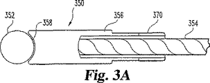
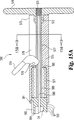
図3A及び3Bは、本発明の固定具の代替的な実施形態を示している。固定具350は、内部に孔360が形成されているビーズ352を含んでいる。ケーブル354の末端362はこの孔内に受け入れられ、ビーズ352はケーブルに固定されている。枢動部材356は、末端358へと延びている長手方向孔364と連通している長手方向溝孔370を含んでいる。孔364及び溝孔370は、ケーブル354をその中に摺動可能に受け入れるような大きさになされている。末端358は、ビーズ352の一部分を受け入れるための球状のキャビティを形成している。固定具350は、図3A及び3Bに示された第1の挿入位置から図1Aに示された固定位置まで枢動可能である。
【0025】
給送器具
本発明は更に、ケーブルと固定具との結合体の挿入のたの給送器具を備えている。上記の固定具と共に使用するための器具が図示されているけれども、この給送器具は、種々のケーブルと固定具との結合体と共に使用されても良く又は使用するようになされても良いことが意図されている。給送器具40の第1の実施形態(図1及び2)は、所望の外科部位を貫通するのに十分な長さ406を有する堅固な金属製の円筒形部材と、基端404から末端402まで延びている長手方向の孔401とを含んでいる。孔401は、固定具の基端部分310がその中に嵌合するのに十分な大きさであるが、固定具の末端部分317がその中に嵌合することができるには小さすぎる。給送器具の好ましい実施形態は、同給送器具の末端を超えて末端方向に延びている固定具30の末端部分を有しているけれども、固定具30は、それが配置されるまで給送器具内に全体が保持され得ることが意図されている。この実施形態(図示せず)においては、ケーブル20は、固定具の偶発的な配置を防止するために、給送器具40に対して固定することができる。
【0026】
ケーブルと固定具との結合体20/30は、ケーブル20に機械的な堅牢性を付与するために使用される給送器具40の助けを借りて組織内に挿入される。ケーブルの基端204は、末端402から孔401を通り基端404を越えるまで給送器具40内を通過せしめられる。固定具の基端310は、基端402に隣接している給送器具の孔401内に着座せしめられ、ケーブルの基端204に張力が維持されて固定具230が第1の位置に保持される。この器具の好ましい実施形態は孔401内に保持された基端304を示しているけれども、基端304はねじを含んでも良く、給送器具40は、器具が給送器具40上にねじによって保持されるように同様に末端に協働可能なねじを有してもよいことが考えられる。別の方法として、基端304と給送器具の末端との間に脆い接続部を設け、この脆い接続部は固定具30が第2の位置へと動くのを可能にするように破壊可能であるようにしてもよい。
【0027】
本発明の給送器具の第2の実施形態(図4,5A及び5B)においては、押し込み手段は、固定具30を第1の位置に維持するためにケーブル20上に基端方向の長手方向の力を解除可能に維持するための手段を含んでいる。
【0028】
この実施形態においては、給送器具70は、基端722を有し且つ末端724に凹部728を有するハンドル部分720を有する本体72を含んでいる。給送器具本体72の頂部721から底部723まで延びている凹部728は、基端725が丸くなっている。長手方向の孔726が、基端722から末端724まで延びており、孔726はケーブル20がその中を通過することができる大きさとされている。
【0029】
給送器具の本体の凹部728内で長手方向に摺動する大きさになされた丸くなされた歯止めハウジング75が、基端側752を介して給送器具本体の末端724に移動可能に固定されている。歯止めハウジング75は、基端側752から末端側754まで歯止めキャビティ758内を延びている長手方向の孔756を更に有している。孔756は、ケーブル20がその中を通過する大きさになされており且つこの器具が使用のために組み立てられたときに給送器具の本体の孔726と連通するようになされている。ばね用孔757が末端側754から歯止めキャビティ758内へと延びており且つ長手方向孔756の上方に配置されている。
【0030】
給送器具70は、更に、基端732において歯止めハウジングの末端側754に取り付けられている内側チューブ73を含んでいる。内側チューブ73は、概して円筒形であり且つ基端732から末端734まで延びており且つケーブル20がその中を通過できるが末端734は固定具の基端部分310が入るには小さすぎる大きさの長手方向の孔736を有している。この孔736は、歯止めハウジングの孔756と連通している。
【0031】
給送器具70のもう一つの部材は、歯止めハウジング75と機械的に連通しているノーズ状(鼻形状の)アセンブリ74である。基端側742は、2つのねじ(図示せず)によって給送器具本体72の末端724に取り付けられている。これらのねじは、ノーズアセンブリ74の傾斜がつけられた末端側744からその中を通って基端側742まで延びている第1及び第2のねじ孔782を介して挿入される。第1及び第2のねじ孔782は、本体の末端724から本体72内へと延びている第3及び第4のねじ孔727(図10B)と合致するように配置されている。
【0032】
ノーズアセンブリ74は、頂部741から底部743まで延びており且つ歯止めハウジング75の丸くなされた末端側754を受け入れる形状になされた丸くなされた凹部748を有している。2つの凹部748,728は、協働して包囲された細長い孔79を形成しており、この細長い孔は、歯止めハウジング75と緊密に且つ摺動可能に結合する大きさになされた幅792と、歯止めハウジング75の長さ755よりも長く、歯止めハウジング75がその中で凹部の基端725に当接する第1の位置からノーズアセンブリの凹部748内の第2の位置(図5Bの点線)まで長手方向に摺動することができるようになされている。
【0033】
ノーズアセンブリ74は、更に、基端側742から末端側744まで延びている長手方向の孔746を有し、この孔は、内側チューブ73がその中を通過し且つ同内側チューブに対して相対的に摺動できるような大きさ及び配置とされている。
【0034】
ノーズアセンブリの末端側744には概して円筒形の外側チューブ76の基端762が取り付けられており、この外側チューブ76は、基端762から末端764まで延びている長手方向の孔766を有している。外側チューブ76は、外側チューブ76の異なる大きさ及び形状が給送器具70と共に使用できるようにノーズアセンブリに取り外し可能に取り付けられても良い。別の方法として、外側チューブ76は、代替的な形状及び寸法の末端部分が取り付けられて種々の固定具形状及びケーブルの直径を収容できるように、基端部分に取り外し可能に取り付けられた末端部分を備えた2つの構成部品(図示せず)を含んでも良い。孔766は、内側チューブ73がその中を通過し且つ固定具の基端部分310がその中へ摺動できるような大きさになされている。図3の固定具と共に使用するための好ましい実施形態においては、孔766は、固定具の末端部分317がその中へと通過するのを阻止するような大きさになされている。この孔766は、ノーズアセンブリの孔746と連通している。外側チューブ76は、固定されるべき組織を貫通するのに十分な堅牢性を有しているのが好ましい。
【0035】
給送器具70は更に、基端側772から末端側774まで延びており且つケーブル20がその中を通過するのを許容する大きさになされた長手方向の孔776を有している歯止め77を含んでいる。歯止め77は、その下方部分が歯止めキャビティ758内に嵌合し且つ長手方向の孔756よりも下方の位置で下方の基端の隅759に隣接して枢動可能に取り付けられるような大きさになされている。歯止め77は、歯止めハウジングのキャビティ758内で、歯止めハウジングのキャビティの末端側761に当接する第1の位置と歯止めハウジングのキャビティの基端側763に当接する第2の位置との間を枢動可能である。
【0036】
歯止めの長手方向孔776は、歯止め77が第1の位置にあってそれによってケーブル20がその中を自由に通過できるときに、歯止めハウジングの孔756と連通するように配置されている。しかしながら、歯止め77が第2の位置に有るときは、孔776は、軸線から十分離れて配置されていて、ケーブル20を挟むことができ、それによって、ケーブル20が長手方向に動くのを阻止することができる。従って、歯止め77を第2の位置に配置することはまた、ケーブル20を長手方向に動くのを抑止する役目をも果たす。
【0037】
歯止め77はまた、末端側774から基端方向に延びているが基端側772まで完全には延びていないばね用孔777をも有している。歯止めばね78がノーズアセンブリの基端側742に取り付けられており且つ歯止めハウジングのばね用孔757内を貫通して歯止めばね用孔777内へと延びて歯止め77を担持している。このように配置されたばね78は、歯止め77を第2の位置へと付勢し、ケーブル20に基端方向の長手方向の力を解除可能にかけ、歯止め77にかけられたこのばねの力によって内側チューブ73を第2の位置へと付勢する。
【0038】
給送器具部材70の各構成部品は、外側チューブ76内での内側チューブ73の摺動が2つの位置間で長手方向に達成されるように相対的な寸法とされている。第1の位置においては、固定具の基端部分310が外側チューブの孔766内にあるときに、内側チューブの末端734は、固定具の基端304から空間を隔てた関係ある。第2の位置においては、内側チューブの末端734は、外側チューブの末端764まで延びていて固定具の基端部分310を外側チューブ76から押し出す。上記から解るように、固定具の基端部分310がこのように押し出されることによって、固定具30は、第1の位置から第2の位置へとはじき出て、この第2の位置で、ケーブル20を基端方向へ引っ張られないように固定することができる。ばね78は、歯止めハウジング75を第1の位置へと付勢している。
【0039】
図6を参照すると、本発明による固定具給送器具の更に別の実施形態が示されている。給送器具800は、末端に隣接して一連の外ねじ836を含む外側チューブ810を有しており、この外ねじ836は、外側チューブ810をノーズ状の円錐形部834に保持するために対応する内側ねじ834と螺合している。内側チューブ812は、ハウジング814内の機構によって外側チューブ810内で摺動可能であり且つ末端813が末端811から隔置された後退位置と末端813が末端811にほぼ隣接する伸長位置との間で制御されている。特に、内側チューブ812は、ばね832によって後退位置へと付勢されているプランジャ830に当接して係合している。
【0040】
既に説明した実施形態と同様に、外側チューブ810は固定具30の少なくとも一部分を受け入れる大きさとされており、一方、内側チューブ812は図2に示されているような固定具の通過を阻止する大きさとされている。従って、末端813に隣接して配置された固定具(図示せず)に接続されたケーブル(図示せず)に張力がかけられたとき、この固定具は内側チューブ812をプランジャ830に当接させる。ケーブルは、プランジャ816内の孔824を貫通して延びている。図6に示されているように、プランジャ816は、ばね822によって係止位置に付勢されている。この位置においては、ケーブルは孔824内に固定されて保持されて動きが阻止されている。従って、ケーブルにかけられた張力は、係止位置に維持され得る。プランジャ816が矢印850の方向に非係止位置内へと動くと、ケーブルは解除される。
【0041】
プランジャ830の動きは、レバー826を介してプランジャ818によって制御される。プランジャ818が矢印860の方向に動くと、レバー826が枢支軸828を中心に動いて同レバーをプランジャ830に抗して押してばね832に打ち勝ち、プランジャ830を内側チューブ812に抗して移動させる。この動きによって、固定具が外側チューブ810から離れて固定位置へと動くのを許容する。好ましい実施形態においては、プランジャ816は、プランジャ818の末端部分819を受け入れるような大きさになされた孔820(点線で示されている)を含んでいる。図6に示した係止位置においては、プランジャ816は、プランジャ818の動きを阻止し、従って、固定具の偶発的な展開を防止する。プランジャ816が矢印850の方向に動かされると、溝孔820はプランジャ818と整合して、末端819が溝孔820内へと動くことができる。
【0042】
クリンピング器具
本発明は、更に、固定具をケーブル、縫合部材又はその他の細長い部材に取り付けるためのクリンピング器具を意図している。固定具を上記の装置に取り付けるために代替的なクリンピング器具を使用してもよいこと及び以下に記載するクリンピング器具は種々の結線及び縫合装置と共に使用され且つ使用するようになされてもよいということは理解されるべきである。本装置のクリンピング器具は、小さい切開部を介して比較的遠い部位にケーブルの軸線に沿ってクリンプする機能に対して望ましいものである。
【0043】
図13を参照すると、本発明のクリンピング器具50は、ケーブル20の長手軸線に沿ってクリンピングできる機能及び一つの動作で切断とクリンピングとができる機能を含むいくつかの利点を提供する。別の方法として、切断とクリンピングとを別個に又は図示した単一の器具と類似の機能及び動作を備えた2つの別個の器具によってなすことができる。クリンピング器具50は、基端524から末端522まで続いた孔521を有する外側の細長いほぼ円筒形の部材52を含んでいる。第1のクリンピングハンドル528が外側部材の基端524に取り付けられ且つ同外側部材から径方向外方に延びている。
【0044】
クリンピング器具50は、更に、ケーブル20がその中を通過するのを許容する大きさになされた孔541を有している内側の細長いほぼ円筒形の部材54を含んでいる。内側円筒形部材54は、外側円筒形部材の孔521内に嵌合し且つ共通の長手軸線を中心に相対的に回転可能なような寸法になされている。第2のクリンピングハンドル548が、外側部材の基端524から基端方向に延びている内側部材の基端544に取り付けられ且つ同内側部材から径方向外方に延びている。
【0045】
ハンドル528及び548は、各々の末端529及び549が約90゜だけ隔置される第1の開放された位置と、末端529,549が概して正反対に位置する第2のクリンピング位置との間を回転可能である。ハンドル528及び548の動きによって、内側部材54と外側部材52とが相対的に回転せしめられる。
【0046】
クリンピング器具50のクリンピング手段が図14Aに示されており、この図は、器具50の末端502を示している。外側部材52の末端522は、孔541のほぼ半分を見えなくする大ざっぱに半月形状の堅固な部分525を有している。長手軸線に対して隔置された関係に配置されている突出部526が、孔541へとつながっている孔に向かって径方向に延びている。
【0047】
内側部材54の末端542は、同内側部材内への二段階の孔以外は孔541の残りの部分を見えなくする堅固な部分545を有している。ハンドル528,548が開放位置にあるときに、外側部材の堅固な部分525と一緒になってその中の口輪94を緊密に包囲するような大きさになされた第1の大ざっぱに半円形の切り取られた部分552が最も末端部分に沿って設けられている。ハンドル528,548が開放位置に有るときに、外側部材の突出部526は切り取られた部分552に隣接して配置される。
【0048】
ケーブル20がその中を自由に摺動するが口輪94がその中へと通過するには小さすぎる寸法になされた第2の大ざっぱに半円形の切り取られた部分554が、堅固な部分545の基端側に隣接して長手方向に設けられている。ハンドル528,548がクリンピング位置へと動かされると、第1の切り取られた部分552は、堅固な部分525及び突出部526に向かって回転せしめられ、その中にある口輪94はケーブル20上にクリンプされる。
【0049】
器具50は、当技術において一般的であるような、ケーブルの長手軸線に直角の方向よりもむしろケーブル20の長手軸線に沿って口輪94をクリンプし、周囲の組織を除去することなく小さい単一の切開部を介して処置を行うことを可能にするという利点を提供することは理解することができる。
【0050】
ケーブル20と口輪94と共に使用するための本発明のクリンピング器具の好ましい実施形態が示されているけれども、この器具は特定の用途のための大きさとしてもよいことが考えられる。更に、内側部材54と外側部材52とは取り外し可能な末端部分を有しても良いことが意図されている。種々の可撓性部材並びにクリンプ形状及び形式に嵌合するように種々の大きさ及び形状の末端部分が交換可能であるようにしても良い。結線、クリンプ及びクリンピングする末端部分は、標準的なクリンピング器具50によって末端ユーザーによる適切な使用を確保するためにユニットとして包装してもよい。
【0051】
修復されるべき組織に対して基端方向に長手方向の張力を適用するための手段もまた提供される。ケーブルに張力を付与するための多くの器具が知られているが、これらのうちの多くは、所望の緊張を達成するために一連のプーリー又はその他の方向変更を必要とするかもしれない。
【0052】
一つの実施形態(図13)においては、内側円筒形部材54は、外側ねじが切られた基端部分550を有している。概して円筒形のテンショナー56は、基端564から末端562まで続いており且つ内側の円筒形部材のねじが切られた基端部分550とかみ合い可能なようになされた長手方向の孔561を有している。ハンドル565が、テンショナー56の回転を容易にするために、径方向に突出する関係でテンショナー56の外側に取り付けられている。
【0053】
このケーブル取り付け手段は、テンショナーの基端564に隣接して配置されたすべり止め51を含んでいる。すべり止め51は、当技術において知られている器具に似ていて、締め付け位置にあるときに、ケーブルの基端204をクランプしてケーブル20が内側円筒形部材54に対して長手方向に動かないように保持するようになされている。解除位置に有るときには、滑り止め51は、ケーブル20が摺動して通過するのを許容する。
【0054】
ケーブル引っ張り手段は、テンショナー56と内側円筒形部材の基端544とを含んでおり、これらの間のねじり動作によって相対的に移動可能であってケーブル20上の張力を変化させるように機能する。例えば、使用時には、内側円筒形部材54とテンショナー56とは互いにかみ合い、ケーブル20は内側円筒形部材の孔541及びテンショナーの孔561を介して挿入され、ケーブルの基端部分は滑り止め51を引き締めることによってクランプされる。テンショナー56を内側円筒形部材54に対してねじを緩めるように回転すると、ケーブル20を基端方向に引っ張る役目が果たされてケーブル上の張力が増す。ケーブル20のねじれを防止するためにナットを押しつけることができる。
【0055】
器具50内には切断手段も設けられており、それによって、ハンドル528,548が開放位置からクリンピング位置へと動かされたときに、ケーブル20は口輪94の基端側の位置か又は同口輪の中で切断される。図14Bを参照すると、切断機構は、各々、外側円筒形部材52及び内側円筒形部材54の孔521,541内に固定されており且つアーム528,548が閉じられたときに正反対に配置されてケーブル20を切断する2つの顎状部材527,547を含んでいる。
【0056】
特定の実施形態においては、口輪94は、典型的には、ステンレス鋼、チタン、又はコバルト−クロム合金のような金属によって作られる。しかしながら、別の実施形態においては、口輪94は、吸収性の又は非吸収性のポリマー材料によって作られても良い。
【0057】
図13に示された緊張機構を図15の代替的な緊張機構と置き換えても良い。この代替的な緊張機構590は、内側部材54の末端584に取り付けられる。外側チューブ575が、末端584の周りに配置され、この末端と内側肩部585との間にばね577が配置される。内側部材54は、緊張機構590を摺動可能に結合するための保持ピン581を受け入れるようになされた少なくとも一つの溝孔582を含んでいる。末端584の外側面上には、内側部材54に対する外側チューブ575の位置を示すために、一連の溝583又はその他のマーキングも設けられている。内側チューブ586は、枢支ピン576によって枢動可能に取り付けられた滑り止め574を含んでいる。滑り止め574は、溝580内に配置されたケーブルを締め付ける締め付け位置と非締め付け位置との間を枢動し且つ外側チューブ内の溝孔578の中に延びている。内側チューブ586は更に、外ねじが切られた部分579を含んでいる。内ねじが切られた孔を有するハンドル570が、外側チューブ575上に枢動可能に取り付けられ且つ保持ばね572によって定位置に保持されている。ハンドル571が回転すると、外側チューブ575がばねに抗して付勢され、それによって、チャネル580内に配置されたケーブル(図示せず)を引き締める。ケーブルにかける引っ張り力は、外側チューブ575がマーキング583の各増分に隣接しているときに、適用されるばねの力に目盛りをつけることによって概算することができる。
【0058】
本発明による引き締め、クリンピング及び切断器具の更に別の実施形態が図16に開示されている。クリンピング器具900は、ノーズ状部材904に取り付けられた外側チューブ902を含んでいる。このノーズ状部材は、後方ハウジング924と連結されている前方ハウジング922に取り付けられている。図17の部分断面図に示されているように、内側チューブ901は、外側チューブ902内に配置されており且つケーブル908を受け入れるための孔917を含んでいる。内側チューブ901内でのケーブル908の位置は、トリガー歯止め906による末端905の方向への動きに対して維持される。トリガー歯止め906は、枢支ピン939によって前方ハウジング922に対して枢動可能に結合されている。図17に示されているように、ばね938が、内側チューブ901の基端に隣接したケーブル908と係合している係合端部907によってトリガー歯止め906をケーブル保持位置へと付勢している。トリガー歯止め906は、ばね938の力に打ち勝ち且つ係合端部907がケーブル908と係合しなくなるようにトリガー歯止め906を溝孔940内へと動かすことによって、非係合位置へと動かすことができる。
【0059】
後方ハウジング924は、ケーブル908に基端913方向への引っ張り力をかけるためのケーブルテンショナーアセンブリ926を含んでいる。テンショナーアセンブリ926は、ハンドル910のハンドル912に対する動きによって引っ張り位置と図16に示された解除位置との間を作動可能である。ハンドル910は、枢支ピン918によって後方ハウジング924に枢動可能に取り付けられている。連結棒915が、枢支ピン916によってハンドル910に結合され且つハンドルを枢支ピン925を介して引っ張りアセンブリ926と連結している。後方ハウジング924に結合されて固定されているハンドル912に向かうハンドル910の動きによって、引っ張りアセンブリ926が基端方向へ動かされる。
【0060】
図16を参照すると、引っ張りアセンブリ926は、同引っ張りアセンブリ926が基端方向に変位せしめられるとケーブル908を把持し且つ末端方向に動いているときにケーブルの通過を可能にする一対の歯止めを含んでいる。歯止め941は、枢動ピン942によって引っ張りアセンブリ926に枢動可能に結合されている。この歯止めは、ばね943によって係止位置へと付勢されている。歯止め941に対向している歯止めは同一のものである。引っ張りアセンブリ926は更に、引っ張りアセンブリが前方へ引っ張られるにつれて歯止めの把持歯がワイヤから外れるときにケーブルにかかる圧力を増加させるか又は減少させるために、ねじ付きの軸945の動きによって調整することができる一組の皿ばね944を含んでいる。ばね944は、溝孔932内のピン925の位置を維持する。ハンドル910と912との間で孔928及び930内に配置されたばね914は、ハンドル910を前方へ付勢する。この動きもまた、引っ張りアセンブリの歯止めを前方壁937に対して付勢し、次いで、歯止めを図16に示された非係合位置へと付勢する。
【0061】
作動時には、引っ張りアセンブリ926は、ケーブル908に基端方向の引っ張り力を付与するように動かされる。既に述べたように、トリガー歯止め906は、ケーブルの基端方向への動きを許容する。引っ張りアセンブリによって基端方向の引っ張り力が解除されると、トリガー歯止め906は、ケーブル908と係合して末端方向への動きを阻止し、それによって引っ張り力を維持し、一方、引っ張りアセンブリの歯止めは係合が外れて、アセンブリが前方位置に戻るのを許容する。この過程は、所望のケーブルの張力が達成されるまで続けることができる。
【0062】
ケーブルテンショナー、クリンパー及びカッター900もまた、クリンピング及び切断ハンドル934及び936を含んでいる。図18を参照すると、ハンドル936は、後方ハウジング924に取り付けられて固定されており、一方、ハンドル934は枢支ピン946によって前方ハウジング922に結合されている。ハンドルは、ハンドル934の突出部950上に取り付けられたばね949によって別個の位置へと付勢され且つ後方ハウジング内の孔951内に収容されている。ハンドル934は、内側チューブの延長部947(図16)を収容するための溝孔948を含んでいる。ハンドル934のハンドル936に向かう直線的な動きは、溝孔948内の内側チューブ延長部947によって内側チューブ901の回転に変換される。内側チューブ及び外側チューブ901及び902の末端は、図14A及び14Bに示されたような形状とされて、外側チューブに対する内側チューブの回転によって口輪のクリンピング及びケーブルの切断が生じる。
【0063】
本発明による引っ張り、クリンピング及び切断器具の更に別の実施形態は、回転運動よりもむしろ構成部品の長手方向の動きに依存している。図19を参照すると、引っ張り、クリンピング及び切断器具955は、内側部材959,外側部材958及びケーブル保持アセンブリ975を含んでいる。ケーブル保持アセンブリ975は、内側部材959内に収容され且つ非係合位置とケーブル956を保持して固定する係合位置との間を移動可能であるように枢動可能に取り付けられた滑り止め977を含んでいるのが好ましい。保持アセンブリ975は、更に、ねじが切られた部分976を含んでいる。内側部材959は、フランジ972を含んでいる。内ねじが切られたナット973が、フランジ972の周囲に配設され且つねじが切られた部分976に係合する。ナット973は、取り付けピン974によって定位置に回転可能に維持されている。
【0064】
内側部材959は、フランジ972に隣接して外ねじが切られた部分971を含んでおり且つ反対側の端部に一対の隔置された枝部978及び979を含み、これらの枝部は、各々、広がった部分980及び981を有している。枝部978は、切断ブレード962及びクリンピング突出部964を含んでおり、一方、枝部979は、対応する切断アンビル963及びクリンピング凹部965を含んでいる。内側部材959は、2つ以上の枝部を含んでいてもよく且つ末端967に隣接して配設された多数の突出部を有していても良い。
【0065】
内側部材959は、好ましくは管状の外側部材958内に配置されている。外側部材958は、末端966に隣接して傾斜面960を含んでいる。この傾斜面の反対側にはフランジ968が設けられている。ナット969が、フランジ968の周囲に配設され且つ取り付けピン970によって枢動可能に保持されている。
【0066】
作動時に、組織片(図示せず)内に固定された末端を有するケーブル956が、内側部材959とケーブル保持アセンブリ975の中に突き通される。ケーブル956に沿って摺動可能な口輪957は、クリンピング突出部964及びクリンピング凹部965に隣接している枝部978及び979内に配置されている。滑り止め977は、回転されてケーブル956と係合する。ナット973は、組織片(図示せず)に対して耐える内側部材に対してケーブル保持アセンブリを動かすために外ねじ976を中心に回転せしめられ、それによってケーブル956に張力をかける。一度所望量の張力がかけられると、ナット969は、ねじ971に対して回転せしめられて、外側部材958を口輪957に向かって下方に付勢する。外側部材958が前進すると、枝部978及び979は、傾斜面960に対して作用することによって、相互に向かって付勢される。このようにして、クリンピング突起964とクリンピング凹部965とが口輪957をクリンプしてケーブル956にしっかりと係合している間に、切断ブレード962と切断アンビル963とは協働して、ケーブル956を切断する。
【0067】
以上、ケーブルに張力をかけ且つ外側部材を動かすためのねじ係合を示したけれども、当業者に知られている他の機構をここに記載した装置に適用してもよいことは考えられる。更に、ナット973は、ケーブル956にかけられる張力の概算をユーザーに提供するために、トルクレンチによって係合させても良い。
【0068】
組織内の孔がクリンピングの結果として他のチューブの直径を越えて著しく大きくされないように外側チューブ内で生じるのが好ましい動きを利用する器具のような、本長手方向のクリンピング器具の変形は本発明の精神に含まれる。
【0069】
代替的な固定具の実施形態
組織固定具の代替的な形態は鳩目型固定具を含んでおり、この鳩目型固定具の構造及び機能が図9及び10に図示されている。鳩目型固定具32は、基端324においてケーブルの末端202に取り付けられ且つ末端322に固定用ねじ79を受け入れるための鳩目孔321を有している。鳩目型固定具32はまた、ケーブル20がその中を通過し且つその中でクリンプされるのを許容するようになされたケーブル孔323を基端324に隣接して備えている。
【0070】
図1,4又は6の給送器具もまた、上記した鳩目型固定具32と共に使用可能である。この場合に、鳩目型固定具32は、給送器具部材の円筒形部分の孔401又は766の末端部分よりも大きい中央部分325を有している。鳩目型固定具32は更に、給送器具部材の円筒形部分の孔401又は766の末端部分内に位置する大きさとされた基端部分326を有している。従って、上記したように、鳩目型固定具の基端部分326は、取り付けられるケーブル20が基端方向に長手方向の張力を受けているときに、孔401又は766内に保持可能である。別の方法として、鳩目型固定具32は、元の形状に回復する傾向がある変形可能な材料によって作られることが考えられる。このような材料によって作られた鳩目型固定具32は、内側チューブ73が鳩目型固定具32を外側チューブ76から押し出すように、外側チューブ76内に受け入れられるように変形することができることが理解されるであろう。固定具は、次いで、そのより大きい元の寸法に回復することができる。
【0071】
本発明はまた、図10及び11に示された骨の孔のプロテクタ150の使用をも意図している。孔プロテクタは、孔に隣接した骨の外面と係合して骨の中を前進しないようになされた面係合部分152を含んでいる。孔プロテクタ152は、骨の孔内へと延びており且つケーブル20の通過のための孔を提供する円筒形部分をも含んでいる。円筒形部分151の外側面は、外れるのを防止するために周囲の骨と係合する粗面を含んでいるのが好ましい。プロテクタが孔の中にねじ込まれるように粗面がねじ止めされることも考えられるが、この表面は、挿入を容易にするための傾斜した導入縁を有する一連の円形の突出部153と、取り外しを阻止する後縁に隣接したキャビティと、を含んでいる。円筒形部分151は実質的に排除され、固定具は面係合部分152を貫通して延びるか又は同係合部分の一部分であることができることも考えられる。
【0072】
面係合部分152は、骨の表面とほぼ同一面内にあることが意図されている。従って、骨の表面に直角に形成された孔のためには、円筒形部分151と面係合部分152とは直角であろう。好ましい実施形態においては、円筒形部分151と面係合部分152との間のコーナー154は丸くなっている。このことは、固定部材がコーナーを横切って摺動するときの固定部材の擦り傷と摩耗とを制限することを意図している。プロテクタは、ケーブル又は縫合部材が骨の孔のコーナーに抗して引っ張られる用途において特に有用である。図10に示されているように、骨用ねじ79とケーブル20とによって固定された鳩目型固定具32は、孔のプロテクタ150の中に延びている。張力がケーブル20にかけられ且つワッシャ14に対して耐えるクリンプされた口輪94によって維持される。孔のプロテクタ150なしでは、ケーブルは、骨の孔の端縁内に食い込んで周囲組織に損傷を及ぼし且つケーブル20上の張力を減じる傾向がある。
【0073】
組織固定方法
上記の装置を使用する方法は、骨の2つの部片を結合するために、図12A〜Eに示されているような以下のステップを含んでいる。これと同じ技術は、2つの異なる骨を結合させるために、他のタイプの組織を結合させるために、又は別のタイプの組織を骨に結合させるために、使用することができることは当業者にとって明らかである[例えば、靱帯92(ここでは、医療用平行靱帯)の骨90(ここでは、脛骨)への固定を示している図8参照]。従って、この例示的な実施形態の記述によって制限することは意図されていない。
【0074】
2つの孔115及び116が骨の部片90及び91内に穿たれ、ケーブルと固定具と給送器具の結合体20/30/40が、固定具30が末端の孔115内に完全に入るまで孔115,116内に挿入される(図12A)。開けられた孔が示されているけれども、固定具30は、この固定具が準備されていない骨又はその他の組織内に押し込まれるように尖った先端を含むことができることも意図されている。ケーブルの張力が開放され、これによって固定具30が回転することができ且つ末端の孔115の末端側に保持される(図12B)。ここに開示された固定具に加えて、この挿入器具は、骨内に埋め込まれるように設計された固定具と共に使用することもできる、即ち、固定具は末端の皮質の骨を出て行かず、その代わりに、網状の骨内に配置されることを意図されている。
【0075】
給送器具30がケーブル20から取り外され、ワッシャ93及び口輪94が、基端の孔に隣接した位置においてケーブルにねじ止めされる(図12C)。ケーブル20は、次いで、クリンピング器具50内に十分深く挿入されて、口輪94が第2の切り取られた部分554に隣接した第1の切り取られた部分552内に配置されるようになされる。ケーブル20は、滑り止め51と共にクランプされ且つ所望の張力となるまで引っ張られる(図12D)。テンショナー56は、滑り止め51がケーブル20をしっかりと保持している間に内側の円筒形部材54に対してねじを緩められ、それによって、骨の部片同士を一緒に引っ張って、これらの部片間に相当な圧縮力をかける。クリンピング器具50は、口輪94をケーブル20上にクリンプし且つケーブル20の切断をも行うために閉じられる(図12E)。別の方法として、最初にクリンプされ次いで別個のケーブル切断器具(図示せず)をより太いタイプのケーブルのために使用することができる。
【0076】
所望ならば、図9に示されたような鳩目型の固定具60をも使用しても良い。この場合には、口輪94がねじ止めされる前で、クリンプがなされた後に、鳩目型の固定具60が基端601にあるケーブル孔602を介してケーブル20上にねじ止めされ、鳩目を形成しているねじ孔604内にねじ61が挿入され、孔90内に挿入されて、鳩目型の固定具60が取り付けられる(図9)。
【0077】
上記した方法は、給送器具と、ここに記載した引っ張り、クリンプし、切断する器具と、の結合体を利用して行うことができる。
縫合材固定装置及び方法
図7Aに示された、軟らかい組織を修復するための縫合材固定装置83は、上記した給送器具40,70又は800のいずれかのような給送器具と共に使用するための縫合材固定具84を含んでいる。
【0078】
縫合材固定具84は、基端844から末端842まで延びている長手軸線を有する細長い部材である。縫合材固定具84もまた、第1の側面847から反対側の第2の側面848まで貫通している一対の横断孔845,846をも有している。横断孔845,846は、縫合材86が貫通するのを許容する大きさとされている。使用時には、縫合材86は、第1の側面847から第2側面848へと孔845を介し、次いで、第2の側面848から第1の側面847へと別の孔を介して通される。
【0079】
縫合材固定具84は、横断孔845,846の基端側の基端844に狭い基端部分843を有しており、この横断孔845,846は、枢動可能な固定具30に対して、既に説明したように、推進器具の孔401又は外側のチューブの孔766内に挿入され且つ支持される大きさとされている。中央部分848は、推進器具の孔401又は外側チューブの孔766内に挿入可能であるために十分大きさ寸法になされている。縫合材固定具84は、枢動可能な固定具30のために、前のとおり、長手軸線にほぼ直角な第2の断面の大きさよりも大きい第1の断面の大きさを、ほぼ長手軸線に沿って有している。
【0080】
縫合材固定具84は、修復されるべき組織85の末端側に対して、縫合材固定具の支えを達成することができる縫合材の端部を引っ張ることによって操作可能であり且つ枢動可能である。使用時には、縫合材86の端部は、切開部の外側に保持可能であるか、さもなければ、一端862が導入切開部88の外側に保持することができ、第2の端部864は、図7Bに示されているように、第2の切開部89を介して引っ張ることができる。
【0081】
半月状の切開部Tのような軟らかい組織の開裂を修復するために装置83を使用する方法は、開裂Tを横切って組織85を穿刺するステップと、給送器具/縫合材/固定具装置を穿刺した孔834内に挿入するステップと、この給送器具を固定具84が開裂Tの遠い方の端部から現れ且つ固定具84が開裂Tにほぼ直角な長さを有し、従って、滑り出さないように操作するステップと、を含んでいる。外科医は、次いで、縫合材86を操作し且つそれを所望通りに縛って修復部を固定することができる。別の方法として、第2の切開部835が図7Bに示されるように開裂Tを横切って隣接部位に作られ、次いで、2つの部片の縫合材が結合されて修復部が強化される。固定具84は、図7Bに示されているように、組織の体内に挿入されるか、用途に応じて、縫合材86を固定するために組織(図示せず)内を完全に推進することができる。
【0082】
以上、本発明を図面及び上記の記載に図示し且つ詳細に説明したが、これらは、図示のためのものであり且つその性質上限定的なものではないと考えられるべきであり、好ましい実施形態のみが示され且つ説明され、本発明の精神に含まれる全ての変更及び変形が包含されることが望まれていることが理解されるべきである。
【図面の簡単な説明】
【図1】 図1Aは、組織を固定できる準備ができた固定位置にある本発明のケーブルと固定具との斜視図である。
図1Bは、給送器具によって給送する準備ができた挿入位置にある本発明のケーブルと固定具との斜視図である。
【図2】 図2Aは、本発明の固定具の頂面図である。
図2Bは、図2Aの固定具の側面図である。
図2Cは、図2Bの固定具の右側面図である。
【図3】 図3Aは、本発明の固定具の代替的な実施形態の頂面図である。
図3Bは、図3Aの固定具の側方断面図である。
【図4】 図4は、本発明の給送器具の代替的な実施形態の分解斜視図である。
【図5】 図5Aは、図4の給送器具の部分断面側面図である。
図5Bは、図5Aの給送器具の部分断面頂面図である。
【図6】 図6は、本発明の給送器具の更に別の実施形態の部分断面側面図である。
【図7】 図7Aは、給送器具の末端によって支持された本発明による縫合固定具を示している。
図7Bは、柔らかい組織の開裂を補修するために使用される図7Aの縫合固定具を示している。
【図8】 図8は、靱帯を骨に固定する際の装置の使用方法の挿入ステップを示している。
【図9】 図9は、給送器具に取り付けられた本発明の鳩目型固定具の前方斜視図である。
【図10】 図10は、骨の孔を貫通して延びているケーブルが取り付けられた骨に固定され且つ第2の固定具によって固定されている図9の鳩目型固定具前方斜視図である。
【図11】 図11Aは、本発明による骨の孔プロテクタの前面図である。
図11Bは、図11Aの骨の孔プロテクタの側方断面図である。
【図12】 図12A〜Eは、骨の2つの部分を一体化して固定する際に本発明の装置を使用する方法を示している。図12Aにおいては、固定具を備え且つケーブルが取り付けられた給送器具が骨の中に挿入されている。図12Bにおいては、固定具が枢動されている。図12Cにおいては、ワッシャと口輪とがケーブルの基端に突き通されており、図12Dにおいては、口輪がケーブルにクリンプされ、図12Eにおいては、ケーブルが切断されて、骨の断片が固定された状態で残っている。
【図13】 図13は、本発明による、引っ張り、クリンピング及び切断器具の側方斜視図である。
【図14】 図14Aは、図13の引っ張り、クリンピング及び切断器具の末端から見た斜視図である。
図14Bは、図14AのB−Bに沿った、引っ張り、クリンピング及び切断器具の末端に隣接した側方斜視断面図である。
【図15】 図15Aは、図13の器具と共に使用するための代替的なケーブル引っ張り機構の側方断面図である。
図15Bは、線B−Bに沿った図15Aの機構の断面図である。
【図16】 図16は、本発明による、引っ張り、クリンピング及び切断器具の代替的な実施形態の側面図である。
【図17】 図17は、図15の器具の部分断面図である。
【図18】 図18は、図15の器具の頂面図である。
【図19】 図19は、本発明による、引っ張り、クリンピング及び切断器具の更に別の実施形態の前方部分断面図である。[0001]
(Background of the Invention)
The present invention relates to surgical instruments and methods, and more particularly to instruments and methods for bone and soft tissue repair.
[0002]
It is a common requirement in orthopedic surgery to fix two or more pieces together such as a bone piece, two or more bones, or a bond between soft tissue and bone. This fixation may include bone bolts that penetrate the two pieces of bone and use a nut to integrate the pieces, bone screws and connection plates, wires that surround at least two pieces of bone, or stitches into tissue. Has been achieved by numerous instruments such as sticking.
[0003]
Such instruments require a relatively large access hole through the surrounding and / or covering tissue to embed the fixture. Large access sites increase patient pain and prolong recovery time. Furthermore, in some locations, surrounding the joints and blood vessels, it is difficult and impractical to make a large access point to reach the appropriate site. Even instruments such as lug bolts that penetrate tissue in a generally linear fashion often have to be reduced from breaking prior to drilling and bolt insertion. In addition, some of these instruments may be difficult to use because it may be difficult to reduce the breakage between the two bone pieces and maintain this breakage reduction while the instrument is inserted. It may be difficult. This is particularly the case for small bone parts where the use of a threaded implant may tend to cause one bone part to rotate relative to another, resulting in misalignment between pieces. It is correct on the piece.
[0004]
A cerclage device is an alternative to an implant that must penetrate the bone to be fixed. Such devices are taught by Miller et al. (US Pat. No. 5,312,410) and Songer et al. (US Pat. No. 5,536,270). These devices rely on passing the cable around the two parts of the bone and then pulling the cable to unite these parts. A significant drawback of these devices is that they require access to the entire circumference of the bone.
[0005]
Thus, there remains a need for a convenient and efficient device for joining two parts of tissue. Such a device should preferably be operable through a relatively small insertion hole to hold and secure the two tissue sections.
[0006]
(Summary of Invention)
The anchoring device according to the present invention comprises an elongate flexible member having a diameter, a proximal end, a distal end and a longitudinal axis, and a proximal end, a distal end, a central portion between the proximal end and the distal end, and between the proximal end and the distal end. And a longitudinal slot extending longitudinally from the proximal end to the central portion, the slot having a width greater than the diameter of the flexible member. And a fastener adapted to be secured adjacent the central portion of the distal end of the flexible member. The fixture includes a first position in which the longitudinal axis of the flexible member and the fixture are generally parallel, and a portion of the flexible member adjacent to a distal end is located in the slot; and The flexible member can be moved relative to the flexible member between a longitudinal position of the flexible member and a second position where the fixture is substantially perpendicular.
[0007]
Another embodiment of a fixation device according to the present invention is an elongate flexible member having a proximal end, a distal end and a first diameter and a fixation device attached to the distal end for insertion through a tissue hole. A fastener configured to move between an insertion configuration configured to and a fixation configuration that impedes passage through the tissue hole, wherein the insertion configuration is a second smaller than twice the first diameter. Having a diameter, the fixed form being adapted to have a third diameter greater than the second diameter.
[0008]
The apparatus also includes a delivery device having a distal end, the distal end being at least a retainer for releasably retaining the retainer in a first position for insertion from at least a portion of the tissue cross-section. The proximal end of the device is releasably received, and the fastener is releasable from the delivery device to secure the flexible member within the cross section of the tissue. The feeder implements a mechanism for releasably applying a longitudinal force to the flexible member in the proximal direction to hold the fixture at the proximal end of the feeder and thereby hold it in a first position. Is included.
[0009]
In one embodiment, the insertion instrument is an inner tube having a longitudinal bore extending from the proximal end to the distal end, which allows the elongated flexible member to pass through and is elongated. An inner tube sized to prevent the fastener attached to the flexible member from passing therethrough, and sized to extend from the proximal end to the distal end and allow the inner tube to pass therethrough; And a mechanism for applying a pulling force to the elongate flexible member and disposed adjacent to the distal end of the inner tube.
[0010]
The apparatus of the present invention further comprises a crimping tool that can include an outer member having an inner passage and an outer passage having an outer diameter. This crimping mechanism can be placed in the inner passage adjacent to the distal end. The crimping mechanism is movable relative to the outer member between a crimping position and an open position.
[0011]
An alternative embodiment of the present invention includes a suture anchoring device for securing a first portion of tissue to a second portion of tissue through a single incision having a longitudinal axis. The anchoring device includes a suture anchor connected to a suture having a first end, a second end, a longitudinal axis and a diameter. The suture anchor has a longitudinal axis extending substantially from the proximal end to the distal end and a first cross-sectional dimension along the longitudinal axis that is greater than the cross-sectional dimension substantially perpendicular to the longitudinal axis. The device further slidably secures the central portion of the suture to the suture fixture so that the first and second ends of the suture can be held outside the incision. Further includes a mechanism for The suture material fixing tool includes a first position where the longitudinal axis of the incision and the suture material fixing tool are substantially parallel to each other, and a second position where the longitudinal axis of the incision and the suture material fixing tool are substantially perpendicular to each other. It can pivot with respect to the suture material.
[0012]
The present invention also includes a bone hole protector having a first portion forming a hole therein for receiving a cable. This first portion is adapted to engage the surface surrounding the bone hole. The protector also includes a fixation extension coupled to the first portion and adapted to extend into the bone so as to prevent movement of the first portion.
[0013]
The present invention further contemplates a method for joining two portions of tissue. The method includes a first fixture, an elongate member attached to the first fixture, a deformable portion slidable on the elongate member and adapted to engage the elongate member. Providing a crimping instrument having a second fixture having an outer member and an inner member movably disposed within the outer member. The first fixture is inserted into a second portion of tissue. The second fixture is pierced by the elongated member. The elongated member is tensioned to urge the first portion of tissue toward the second portion of tissue. The elongate member is pierced through the crimping instrument and the inner member of the crimping member is moved relative to the outer member, thereby deforming the deformable portion of the second fixture and maintaining the tension applied to the elongate member. The
[0014]
One of the objects of the present invention is to provide a member for fixing tissue.
Another object of the present invention is to provide an apparatus for delivering a tissue fixation member.
It is a further object of the present invention to provide such a device that can also tighten and tie the securing member.
A further object of the present invention is to provide a crimping device.
It is a further object of the present invention to provide a method for delivering a tissue fastener to a surgical site.
It is a further object of the present invention to provide a member for securing a suture.
It is a further object of the present invention to provide an apparatus for delivering a suture anchor.
It is a further object of the present invention to provide a method for delivering a suture anchor to a surgical site.
It is a further object of the present invention to provide a bone hole protector.
Other objects and advantages of the present invention will become apparent from the following description.
[0015]
(Description of Preferred Embodiment)
To facilitate an understanding of the principles of the invention, reference will be made to the embodiments illustrated in the drawings and specific terminology will be used to describe the embodiments. However, they are not intended to limit the scope of the present invention, and modifications and variations to the illustrated apparatus and further applications of the principles of the present invention are within the technical fields related to the present invention. It will normally be conceived by those skilled in the art.
[0016]
Referring to FIG. 1A, a
[0017]
Referring to FIG. 1A, the
[0018]
Cable fixture
At the
[0019]
The
[0020]
The
[0021]
In addition, the
[0022]
In a preferred embodiment, the fixture
[0023]
The
[0024]
3A and 3B show an alternative embodiment of the fixture of the present invention. The
[0025]
Feeding equipment
The invention further comprises a feeding device for the insertion of the cable / fixture combination. Although an instrument for use with the above fixture is shown, the feeder may be used or adapted for use with various cable and fixture combinations. Is intended. The first embodiment of the delivery instrument 40 (FIGS. 1 and 2) includes a rigid metal cylindrical member having a length 406 sufficient to penetrate the desired surgical site and a
[0026]
The cable /
[0027]
In the second embodiment of the delivery device of the present invention (FIGS. 4, 5A and 5B), the pusher means is a longitudinal longitudinal direction on the
[0028]
In this embodiment, the
[0029]
A
[0030]
The
[0031]
Another member of the
[0032]
The
[0033]
The
[0034]
A
[0035]
The
[0036]
The pawl
[0037]
The
[0038]
Each component of the
[0039]
Referring to FIG. 6, yet another embodiment of a fastener feeder according to the present invention is shown. The
[0040]
Similar to the previously described embodiments, the
[0041]
The movement of the
[0042]
Crimping equipment
The present invention further contemplates a crimping instrument for attaching the fastener to a cable, suture member or other elongated member. Alternative crimping instruments may be used to attach the fasteners to the devices described above, and the crimping instruments described below may be used and adapted for use with various termination and suturing devices. Should be understood. The crimping instrument of the present device is desirable for its ability to crimp along the cable axis to a relatively distant site through a small incision.
[0043]
Referring to FIG. 13, the crimping
[0044]
The crimping
[0045]
[0046]
The crimping means of the crimping
[0047]
The
[0048]
A second roughly semi-circular cut-out
[0049]
The
[0050]
Although a preferred embodiment of the crimping instrument of the present invention for use with
[0051]
Means are also provided for applying longitudinal tension proximally to the tissue to be repaired. Many devices are known for tensioning cables, but many of these may require a series of pulleys or other direction changes to achieve the desired tension.
[0052]
In one embodiment (FIG. 13), the inner
[0053]
The cable attachment means includes a non-slip 51 disposed adjacent the tensioner
[0054]
The cable tensioning means includes a
[0055]
Cutting means is also provided in the
[0056]
In certain embodiments, the
[0057]
The tensioning mechanism shown in FIG. 13 may be replaced with the alternative tensioning mechanism of FIG. This
[0058]
Yet another embodiment of a tightening, crimping and cutting instrument according to the present invention is disclosed in FIG. Crimping
[0059]
The
[0060]
Referring to FIG. 16, the
[0061]
In operation, the
[0062]
Cable tensioner, crimper and
[0063]
Yet another embodiment of the pulling, crimping and cutting instrument according to the present invention relies on the longitudinal movement of the component rather than the rotational movement. Referring to FIG. 19, the tensioning, crimping and cutting
[0064]
[0065]
[0066]
In operation, a
[0067]
While screw engagement has been shown to tension the cable and move the outer member, it is contemplated that other mechanisms known to those skilled in the art may be applied to the devices described herein. Furthermore, the
[0068]
Variations on this longitudinal crimping instrument, such as instruments that utilize movement that preferably occurs in the outer tube so that the holes in the tissue are not significantly enlarged beyond the diameter of the other tube as a result of crimping, are disclosed herein. Included in the spirit.
[0069]
Alternative fixture embodiments
Alternative forms of tissue fasteners include eyelet-type fasteners, the structure and function of which is shown in FIGS. 9 and 10. The
[0070]
The feeding device of FIGS. 1, 4 or 6 can also be used with the
[0071]
The present invention also contemplates the use of the
[0072]
The
[0073]
Tissue fixing method
The method of using the above apparatus includes the following steps as shown in FIGS. 12A-E for joining two pieces of bone. It will be appreciated by those skilled in the art that this same technique can be used to join two different bones, to join other types of tissue, or to join another type of tissue to bone. Clearly [see, eg, FIG. 8 showing fixation of ligament 92 (here, medical parallel ligament) to bone 90 (here, tibia)]. Accordingly, it is not intended to be limited by the description of this exemplary embodiment.
[0074]
Two
[0075]
The
[0076]
If desired, a eyelet shaped fixture 60 as shown in FIG. 9 may also be used. In this case, before the
[0077]
The method described above can be performed using a combination of a feeding instrument and the instrument described herein for pulling, crimping and cutting.
Suture fixing device and method
The
[0078]
The
[0079]
The
[0080]
The
[0081]
A method of using the
[0082]
While the invention has been illustrated and described in detail in the drawings and foregoing description, the same is to be considered as illustrative and not restrictive in character and is a preferred embodiment. It should be understood that only changes and modifications have been shown and described, and are intended to encompass all modifications and variations that fall within the spirit of the invention.
[Brief description of the drawings]
FIG. 1A is a perspective view of a cable and fixture of the present invention in a fixed position ready to fix tissue.
FIG. 1B is a perspective view of the cable and fixture of the present invention in the insertion position ready to be fed by the feeder.
FIG. 2A is a top view of the fixture of the present invention.
2B is a side view of the fixture of FIG. 2A.
2C is a right side view of the fixture of FIG. 2B.
FIG. 3A is a top view of an alternative embodiment of the fixture of the present invention.
3B is a cross-sectional side view of the fixture of FIG. 3A.
FIG. 4 is an exploded perspective view of an alternative embodiment of the delivery device of the present invention.
5A is a partial cross-sectional side view of the delivery device of FIG. 4. FIG.
5B is a partial cross-sectional top view of the delivery device of FIG. 5A.
FIG. 6 is a partial cross-sectional side view of yet another embodiment of the delivery device of the present invention.
FIG. 7A shows a suture anchor according to the present invention supported by the distal end of a delivery device.
FIG. 7B shows the suture anchor of FIG. 7A used to repair a soft tissue tear.
FIG. 8 shows the insertion step of the method of use of the device in securing the ligament to the bone.
FIG. 9 is a front perspective view of the eyelet-type fixture of the present invention attached to a feeding device.
FIG. 10 is a front perspective view of the eyelet-shaped fixture of FIG. 9 secured to a bone to which a cable extending through the bone hole is attached and secured by a second fixture. .
FIG. 11A is a front view of a bone hole protector according to the present invention.
FIG. 11B is a side cross-sectional view of the bone hole protector of FIG. 11A.
FIGS. 12A-E illustrate a method of using the device of the present invention in securing and fixing two portions of bone. FIG. In FIG. 12A, a delivery device with fasteners and attached cables is inserted into the bone. In FIG. 12B, the fixture is pivoted. In FIG. 12C, the washer and muzzle are pierced to the proximal end of the cable, in FIG. 12D the muzzle is crimped to the cable, and in FIG. Remains fixed.
FIG. 13 is a side perspective view of a pulling, crimping and cutting instrument according to the present invention.
14A is a perspective view from the distal end of the tensioning, crimping and cutting instrument of FIG. 13. FIG.
14B is a side perspective cross-sectional view adjacent to the distal end of the pulling, crimping and cutting instrument along BB of FIG. 14A.
15A is a side cross-sectional view of an alternative cable pulling mechanism for use with the instrument of FIG.
FIG. 15B is a cross-sectional view of the mechanism of FIG. 15A along line BB.
FIG. 16 is a side view of an alternative embodiment of a pulling, crimping and cutting instrument according to the present invention.
FIG. 17 is a partial cross-sectional view of the instrument of FIG.
FIG. 18 is a top view of the device of FIG. 15;
FIG. 19 is a front partial cross-sectional view of yet another embodiment of a pulling, crimping and cutting instrument according to the present invention.
Claims (20)
開放されている基端と、閉塞されている末端と、同基端と末端との間の中央部分と、前記基端と末端との間に延びている長手軸線と、を有する固定具であって、前記閉塞されている末端と開放されている基端との間に延びている長手方向孔と、前記基端から前記中央部分まで長手方向に延びている長手方向溝孔とを含み、同長手方向溝孔は、前記可撓性部材の直径よりも大きい幅を有し、前記可撓性部材の末端は前記長手方向孔内に固定されている、固定具と、を含み、
前記固定具は、前記可撓性部材の長手軸線と当該固定具とがほぼ平行である第1の位置と、前記可撓性部材の長手軸線と当該固定具の長手軸線とがほぼ直角である第2の位置との間を、前記可撓性部材に対して移動可能であるようになされた、固定具装置。An elongate flexible member having a diameter, a proximal end, a distal end, and a longitudinal axis;
A fixture having an open proximal end, a closed distal end, a central portion between the proximal end and the distal end, and a longitudinal axis extending between the proximal end and the distal end. Te, a longitudinal bore extending between the proximal end which is open and ends being the closing, and a longitudinal slot from the base end and extends longitudinally to said central portion, said A longitudinal slot having a width greater than the diameter of the flexible member, the distal end of the flexible member being secured within the longitudinal hole, and
The fixture, the a longitudinal axis and said fixture of the flexible member and the first position Ru der substantially parallel, and are substantially perpendicular to the longitudinal axis of the longitudinal axis and the fixture of the flexible member A fixture device adapted to be movable relative to the flexible member between a second position.
前記固定具が、前記中央部分上の前記長手方向溝孔に隣接した湾曲した担持面を含み、当該湾曲した担持面は、前記第2の位置において、前記可撓性部材と前記固定具との間の接触面を増大させるようになされている、固定具装置。The fixture device according to claim 1,
The fixture includes a curved carrier surface adjacent to the longitudinal slot on the central portion, the curved carrier surface between the flexible member and the fixture in the second position. Fixture device adapted to increase the contact surface between .
前記可撓性部材が接着剤によって前記長手方向孔内に固着されている、固定具装置。 The fixture device according to claim 1 ,
A fixture device wherein the flexible member is secured in the longitudinal bore by an adhesive.
前記可撓性部材が、前記長手方向孔に隣接して前記固定具をクリンプすることによって同長手方向孔に固定されている、固定具装置。 The fixture device according to claim 1 ,
Said flexible member, said longitudinal bore in adjacent by crimping the fixture is fixed to the longitudinal bore, the fixture device.
前記固定具の基端は、前記長手軸線に対して角度がつけられており、前記長手方向溝孔と反対側の基端は、同長手方向溝孔に隣接した基端よりもより基端側に延びており、それによって、前記角度が付けられた基端の表面に対する係合が、前記固定具を前記第2の位置に向かって回転させる傾向がある、固定具装置。The fixture device according to claim 1,
The proximal end of the fixture, the are angled to the longitudinal axis, opposite the proximal end and the longitudinal slot is more proximal to the proximal end adjacent to the longitudinal slot A fastener device wherein the engagement with the angled proximal surface tends to cause the fixture to rotate toward the second position.
前記可撓性部材が前記固定具に取り付けられて固定されており、同可撓性部材は、前記第1の位置と第2の位置との間の動きを許容するように変形する、固定具装置。The fixture device according to claim 1,
The flexible member is attached to and fixed to the fixture, and the flexible member is deformed to allow movement between the first position and the second position. apparatus.
前記固定具が前記第2の位置に向かって付勢されている、固定具装置。The fixture device according to claim 1,
A fixture device, wherein the fixture is biased toward the second position.
前記可撓性部材がケーブルであり、同ケーブルは、前記固定具に隣接して曲げられて、前記第2の位置に向かう前記付勢を形成している、固定具装置。The fixture device according to claim 7,
The fixture device, wherein the flexible member is a cable, and the cable is bent adjacent to the fixture to form the bias toward the second position.
基端と、末端と、同基端と末端との間の中央部分と、前記基端と末端との間に延びている長手軸線と、を有する固定具であって、前記末端は前記基端よりも大きく、前記基端は、給送器具を受け入れるようになされており、前記末端は、前記給送器具内への受け入れを阻止する大きさとされ、更に、前記基端から前記中央部分まで長手方向に延びている長手方向溝孔を含み、同長手方向溝孔は、前記可撓性部材の直径よりも大きい幅を有し、前記可撓性部材の末端が当該固定具に連結されている前記固定具と、を含み、 A fixture having a proximal end, a distal end, a central portion between the proximal end and the distal end, and a longitudinal axis extending between the proximal end and the distal end, the distal end being the proximal end The proximal end is adapted to receive a delivery device, the distal end is sized to prevent receipt into the delivery device, and further longitudinally from the proximal end to the central portion. A longitudinal slot extending in a direction, the longitudinal slot having a width greater than the diameter of the flexible member, the distal end of the flexible member being connected to the fixture. Including the fixture,
前記固定具は、前記基端が前記給送器具内に配置されたときに前記可撓性部材の長手軸線と当該固定具とがほぼ平行となる第1の位置と、前記可撓性部材の長手軸線と当該固定具の長手軸線とがほぼ直角である第2の位置との間を、前記可撓性部材に対して移動可能であるようになされた、固定具装置。 The fixture includes a first position where the longitudinal axis of the flexible member and the fixture are substantially parallel when the proximal end is disposed in the feeder, and the flexible member A fixture device adapted to be movable relative to the flexible member between a second position where the longitudinal axis and the longitudinal axis of the fixture are substantially perpendicular.
前記固定具が前記基端と前記末端との間に配置された外側肩部を含み、当該肩部は、前記給送器具に当接係合して前記給送器具内での前記固定具の動きを制限するようになされている、固定具装置。 The fixture device according to claim 9,
The fixture includes an outer shoulder disposed between the proximal end and the distal end, the shoulder abuttingly engaging the feeder device and the fixture within the feeder device. A fixture device designed to limit movement.
前記給送器具は、前記固定具を組織の中を前進させるために十分な堅牢性を有し、且つ前記固定具の基端を解除可能に受け入れ且つ前記肩部と当接係合するようになされた末端を有し、前記固定具の末端は、前記給送器具の末端を越えて末端方向に延びている、固定具装置。A fixture device according to claim 10,
The delivery device, the fixture has sufficient robustness to advance through the tissue, and to abutting engagement and releasably receiving and said shoulder portion proximal of said fastener A fastener apparatus having a distal end made, the distal end of the fixture extending distally beyond the distal end of the delivery device.
前記可撓性部材が生体吸収性の材料によって作られている、固定具装置。The fixture device according to claim 1,
A fixture device, wherein the flexible member is made of a bioabsorbable material.
前記固定具が生体吸収性の材料によって作られている、固定具装置。The fixture device according to claim 1,
A fixture device, wherein the fixture is made of a bioabsorbable material.
前記可撓性部材と前記固定具とが、生体適合性の材料によって作られている、固定具装置。The fixture device according to claim 1,
A fixture device, wherein the flexible member and the fixture are made of a biocompatible material.
前記固定具がほぼ円筒形であり且つ第2の直径を有しており、同第2の直径が前記可撓性部材の直径の2倍よりも小さい、固定具装置。The fixture device according to claim 1,
A fixture apparatus, wherein the fixture is substantially cylindrical and has a second diameter, the second diameter being less than twice the diameter of the flexible member.
前記固定具が前記第2の位置にあるときに、前記可撓性部材を組織の部片を横切って張りつめた状態に維持するために、前記可撓性部材を前記基端に隣接して係合させて固定するようになされた第2の固定部材を更に含む、固定具装置。The fixture device according to claim 1,
When the fixture is in the second position, the flexible member is engaged adjacent the proximal end to maintain the flexible member taut across the tissue piece. A fixture device further comprising a second securing member adapted to be secured together.
前記第2の固定具が変形可能な部分を含み、同変形可能な部分は、前記可撓性部材と係合して固定されるように変形可能である、固定具装置。A fixture device according to claim 16, comprising:
The fixture device wherein the second fixture includes a deformable portion, the deformable portion being deformable to engage and be fixed with the flexible member.
前記第2の固定具がワッシャと口輪とを含んでいる、固定具装置。A fixture device according to claim 17,
The fixture device, wherein the second fixture includes a washer and a muzzle.
前記第2の固定具が鳩目型の固定具を含み、同鳩目型の固定具は、前記可撓性部材を受け入れるための第1の孔と、隣接する骨の中へと延びるようになされた固定部材を受け入れるための第2の孔と、を有している、固定具装置。A fixture device according to claim 16, comprising:
The second fixture includes an eyelet-type fixture, the eyelet-type fixture being adapted to extend into a first hole for receiving the flexible member and into an adjacent bone. A fastener device having a second hole for receiving a securing member.
前記可撓性部材と係合して固定するための変形可能な口輪を更に含み、同口輪は、少なくとも一つの方向において、前記可撓性部材が前記鳩目型の第1の孔を通る動きを阻止するために、前記鳩目孔よりも大きく作られている、固定具装置。A fixture device according to claim 19, comprising:
Further comprising a deformable mouth ring for engaging and fixing with the flexible member, the mouth ring passing through the first eyelet of the eyelet shape in at least one direction. A fixture device that is made larger than the eyelet to prevent movement.
Applications Claiming Priority (3)
| Application Number | Priority Date | Filing Date | Title |
|---|---|---|---|
| US09/013,434 | 1998-01-26 | ||
| US09/013,434 US6068648A (en) | 1998-01-26 | 1998-01-26 | Tissue anchoring system and method |
| PCT/US1999/001203 WO1999037219A1 (en) | 1998-01-26 | 1999-01-20 | Tissue anchoring system and method |
Publications (2)
| Publication Number | Publication Date |
|---|---|
| JP2002511281A JP2002511281A (en) | 2002-04-16 |
| JP4065371B2 true JP4065371B2 (en) | 2008-03-26 |
Family
ID=21759950
Family Applications (1)
| Application Number | Title | Priority Date | Filing Date |
|---|---|---|---|
| JP2000528214A Expired - Lifetime JP4065371B2 (en) | 1998-01-26 | 1999-01-20 | Tissue fixation device and method |
Country Status (6)
| Country | Link |
|---|---|
| US (4) | US6068648A (en) |
| EP (1) | EP1051114B1 (en) |
| JP (1) | JP4065371B2 (en) |
| KR (1) | KR20010040394A (en) |
| AU (1) | AU2461799A (en) |
| WO (1) | WO1999037219A1 (en) |
Families Citing this family (490)
| Publication number | Priority date | Publication date | Assignee | Title |
|---|---|---|---|---|
| US5718717A (en) | 1996-08-19 | 1998-02-17 | Bonutti; Peter M. | Suture anchor |
| US5766183A (en) | 1996-10-21 | 1998-06-16 | Lasersurge, Inc. | Vascular hole closure |
| US5893850A (en) | 1996-11-12 | 1999-04-13 | Cachia; Victor V. | Bone fixation device |
| US20050143734A1 (en) * | 1996-11-12 | 2005-06-30 | Cachia Victor V. | Bone fixation system with radially extendable anchor |
| US6648890B2 (en) | 1996-11-12 | 2003-11-18 | Triage Medical, Inc. | Bone fixation system with radially extendable anchor |
| US6632224B2 (en) | 1996-11-12 | 2003-10-14 | Triage Medical, Inc. | Bone fixation system |
| US6045551A (en) | 1998-02-06 | 2000-04-04 | Bonutti; Peter M. | Bone suture |
| US6102934A (en) * | 1998-06-02 | 2000-08-15 | Li; Lehmann K. | Anchor tool and method and apparatus for emplacing anchor in a borehole |
| US6368326B1 (en) * | 1998-09-28 | 2002-04-09 | Daos Limited | Internal cord fixation device |
| US7410489B2 (en) * | 1998-09-28 | 2008-08-12 | Daos Limited | Internal cord fixation device |
| US6045572A (en) * | 1998-10-16 | 2000-04-04 | Cardiac Assist Technologies, Inc. | System, method and apparatus for sternal closure |
| GB2346408B (en) * | 1999-02-08 | 2001-01-03 | Latchways Plc | Safety line anchor |
| US6660022B1 (en) | 1999-06-01 | 2003-12-09 | Smith & Nephew, Inc. | Rotor blade anchor and tool for installing same |
| US20040122456A1 (en) * | 2002-12-11 | 2004-06-24 | Saadat Vahid C. | Methods and apparatus for gastric reduction |
| US6626899B2 (en) | 1999-06-25 | 2003-09-30 | Nidus Medical, Llc | Apparatus and methods for treating tissue |
| US6991643B2 (en) | 2000-12-20 | 2006-01-31 | Usgi Medical Inc. | Multi-barbed device for retaining tissue in apposition and methods of use |
| DE60028772T2 (en) | 1999-07-02 | 2007-03-29 | Quickpass, Inc. | SURGICAL SEWING DEVICE |
| CA2379410C (en) | 1999-07-08 | 2015-12-08 | Lee Angros | Antigen recovery and/or staining apparatus and method |
| US6596014B2 (en) * | 1999-07-13 | 2003-07-22 | Scion Cardio-Vascular, Inc. | Suture with toggle and method of manufacture therefor |
| US6368343B1 (en) | 2000-03-13 | 2002-04-09 | Peter M. Bonutti | Method of using ultrasonic vibration to secure body tissue |
| US6447516B1 (en) | 1999-08-09 | 2002-09-10 | Peter M. Bonutti | Method of securing tissue |
| US8128698B2 (en) | 1999-10-20 | 2012-03-06 | Anulex Technologies, Inc. | Method and apparatus for the treatment of the intervertebral disc annulus |
| US6524317B1 (en) | 1999-12-30 | 2003-02-25 | Opus Medical, Inc. | Method and apparatus for attaching connective tissues to bone using a knotless suture anchoring device |
| WO2001049190A1 (en) * | 2000-01-03 | 2001-07-12 | Freedland Y | Flip-wing tissue retainer |
| US6635073B2 (en) | 2000-05-03 | 2003-10-21 | Peter M. Bonutti | Method of securing body tissue |
| US7094251B2 (en) | 2002-08-27 | 2006-08-22 | Marctec, Llc. | Apparatus and method for securing a suture |
| US9138222B2 (en) | 2000-03-13 | 2015-09-22 | P Tech, Llc | Method and device for securing body tissue |
| US8932330B2 (en) * | 2000-03-13 | 2015-01-13 | P Tech, Llc | Method and device for securing body tissue |
| US7963966B2 (en) * | 2000-06-06 | 2011-06-21 | Cole J Dean | Bone fixation system and method of use |
| EP1299041B1 (en) * | 2000-06-12 | 2006-10-04 | Jeffrey E. Yeung | Intervertebral disc repair |
| DE20122783U1 (en) * | 2000-06-17 | 2007-11-15 | Leica Microsystems Cms Gmbh | Arrangement for examining microscopic specimens with a scanning microscope and illumination device for a scanning microscope |
| US6325804B1 (en) * | 2000-06-28 | 2001-12-04 | Ethicon, Inc. | Method for fixing a graft in a bone tunnel |
| US6451030B2 (en) | 2000-06-30 | 2002-09-17 | Li Medical Technologies, Inc. | Rotor blade anchor and tool for installing same particularlly for arthroscopic installation |
| US6638312B2 (en) * | 2000-08-04 | 2003-10-28 | Depuy Orthopaedics, Inc. | Reinforced small intestinal submucosa (SIS) |
| US8366787B2 (en) | 2000-08-04 | 2013-02-05 | Depuy Products, Inc. | Hybrid biologic-synthetic bioabsorbable scaffolds |
| US6733509B2 (en) * | 2000-08-25 | 2004-05-11 | Sutura, Inc. | Suture cutter |
| US6652561B1 (en) * | 2000-10-13 | 2003-11-25 | Opus Medical, Inc | Method and apparatus for attaching connective tissues to bone using a perforated suture anchoring device |
| US6635059B2 (en) * | 2001-01-03 | 2003-10-21 | Bernard L. Randall | Cannulated locking screw system especially for transiliac implant |
| US8313496B2 (en) * | 2001-02-02 | 2012-11-20 | Lsi Solutions, Inc. | System for endoscopic suturing |
| US6770076B2 (en) | 2001-02-12 | 2004-08-03 | Opus Medical, Inc. | Method and apparatus for attaching connective tissues to bone using a knotless suture anchoring device |
| US7686807B2 (en) * | 2001-03-22 | 2010-03-30 | Interventional Spine, Inc. | Tool for bone fixation device |
| US6887243B2 (en) | 2001-03-30 | 2005-05-03 | Triage Medical, Inc. | Method and apparatus for bone fixation with secondary compression |
| US6511481B2 (en) | 2001-03-30 | 2003-01-28 | Triage Medical, Inc. | Method and apparatus for fixation of proximal femoral fractures |
| US20060069429A1 (en) * | 2001-04-24 | 2006-03-30 | Spence Paul A | Tissue fastening systems and methods utilizing magnetic guidance |
| US8202315B2 (en) | 2001-04-24 | 2012-06-19 | Mitralign, Inc. | Catheter-based annuloplasty using ventricularly positioned catheter |
| US6619291B2 (en) * | 2001-04-24 | 2003-09-16 | Edwin J. Hlavka | Method and apparatus for catheter-based annuloplasty |
| US6960213B2 (en) * | 2001-05-23 | 2005-11-01 | Medicinelodge, Inc. | Apparatus and method for orthopedic fixation |
| US6547800B2 (en) | 2001-06-06 | 2003-04-15 | Opus Medical, Inc. | Method and apparatus for attaching connective tissues to bone using a cortical bone anchoring device |
| US8025896B2 (en) | 2001-07-16 | 2011-09-27 | Depuy Products, Inc. | Porous extracellular matrix scaffold and method |
| DE60239342D1 (en) | 2001-07-16 | 2011-04-14 | Depuy Products Inc | DEVICE FOR THE REPAIR OF CARTILING MATERIAL |
| US7163563B2 (en) * | 2001-07-16 | 2007-01-16 | Depuy Products, Inc. | Unitary surgical device and method |
| US7819918B2 (en) | 2001-07-16 | 2010-10-26 | Depuy Products, Inc. | Implantable tissue repair device |
| AU2002316694B2 (en) * | 2001-07-16 | 2007-09-06 | Depuy Products, Inc. | Hybrid biologic/synthetic porous extracellular matrix scaffolds |
| US8012205B2 (en) | 2001-07-16 | 2011-09-06 | Depuy Products, Inc. | Cartilage repair and regeneration device |
| JP4197158B2 (en) | 2001-07-16 | 2008-12-17 | デピュイ・プロダクツ・インコーポレイテッド | Devices with naturally occurring biologically derived materials |
| WO2003007786A2 (en) * | 2001-07-16 | 2003-01-30 | Depuy Products, Inc. | Porous delivery scaffold and method |
| JP4294474B2 (en) | 2001-07-16 | 2009-07-15 | デピュイ・プロダクツ・インコーポレイテッド | Meniscus reproduction device |
| DE60239559D1 (en) * | 2001-10-22 | 2011-05-05 | Interventional Therapies Llc | WUNDNÄHVORRICHTUNG |
| US20030078601A1 (en) * | 2001-10-22 | 2003-04-24 | Oleg Shikhman | Crimping and cutting device |
| US6685706B2 (en) * | 2001-11-19 | 2004-02-03 | Triage Medical, Inc. | Proximal anchors for bone fixation system |
| US6719765B2 (en) | 2001-12-03 | 2004-04-13 | Bonutti 2003 Trust-A | Magnetic suturing system and method |
| US6780198B1 (en) | 2001-12-06 | 2004-08-24 | Opus Medical, Inc. | Bone anchor insertion device |
| ATE311817T1 (en) | 2002-03-14 | 2005-12-15 | Jeffrey E Yeung | SUTH ANCHOR AND ADAPTATION DEVICE |
| US9155544B2 (en) | 2002-03-20 | 2015-10-13 | P Tech, Llc | Robotic systems and methods |
| GB0208667D0 (en) * | 2002-04-16 | 2002-05-29 | Atlantech Medical Devices Ltd | A transverse suspension device |
| US7326222B2 (en) * | 2002-05-01 | 2008-02-05 | Arthrex, Inc. | Suture tensioning device |
| US7922772B2 (en) * | 2002-05-24 | 2011-04-12 | Zimmer, Inc. | Implants and related methods and apparatus for securing an implant on an articulating surface of an orthopedic joint |
| US7771483B2 (en) * | 2003-12-30 | 2010-08-10 | Zimmer, Inc. | Tibial condylar hemiplasty implants, anchor assemblies, and related methods |
| US6793678B2 (en) | 2002-06-27 | 2004-09-21 | Depuy Acromed, Inc. | Prosthetic intervertebral motion disc having dampening |
| US20040166169A1 (en) * | 2002-07-15 | 2004-08-26 | Prasanna Malaviya | Porous extracellular matrix scaffold and method |
| JP4988203B2 (en) * | 2002-07-19 | 2012-08-01 | インターヴェンショナル スパイン、インコーポレイテッド | Spinal fixation method and spinal fixation device |
| ATE447371T1 (en) * | 2002-09-24 | 2009-11-15 | Ethicon Endo Surgery Inc | SURGICAL ULTRASONIC INSTRUMENT WITH INCREASED WORKING LENGTH |
| NZ539136A (en) * | 2002-10-21 | 2008-04-30 | Mitralign Inc | Method and apparatus for performing catheter-based annuloplasty using local plications |
| US20050119735A1 (en) | 2002-10-21 | 2005-06-02 | Spence Paul A. | Tissue fastening systems and methods utilizing magnetic guidance |
| US20040199169A1 (en) * | 2002-11-20 | 2004-10-07 | Koons Kirk C. | Cable clamp tool for surgical applications |
| US7070601B2 (en) * | 2003-01-16 | 2006-07-04 | Triage Medical, Inc. | Locking plate for bone anchors |
| EP1605873A4 (en) * | 2003-02-28 | 2008-05-21 | Triage Medical Inc | Tool for bone fixation device |
| US7833225B2 (en) * | 2003-04-24 | 2010-11-16 | Orthohelix Surgical Designs, Inc. | Method and device for bone stabilization using a threaded compression wire |
| US7497864B2 (en) | 2003-04-30 | 2009-03-03 | Marctec, Llc. | Tissue fastener and methods for using same |
| US6951561B2 (en) * | 2003-05-06 | 2005-10-04 | Triage Medical, Inc. | Spinal stabilization device |
| JP4166632B2 (en) * | 2003-06-06 | 2008-10-15 | オリンパス株式会社 | Suture device |
| US7722644B2 (en) * | 2003-06-11 | 2010-05-25 | Medicine Lodge, Inc. | Compact line locks and methods |
| US7806909B2 (en) * | 2003-06-11 | 2010-10-05 | Medicine Lodge Inc. | Line lock threading systems and methods |
| US7341558B2 (en) * | 2003-09-19 | 2008-03-11 | Medcanica, Llc | Pericardial retractor |
| US7896917B2 (en) * | 2003-10-15 | 2011-03-01 | Biomet Sports Medicine, Llc | Method and apparatus for graft fixation |
| US7682374B2 (en) | 2003-10-21 | 2010-03-23 | Arthrocare Corporation | Knotless suture lock and bone anchor implant method |
| US7645282B2 (en) * | 2003-11-20 | 2010-01-12 | Osseus, Llc | Method and device for cutting surgical wire or cable |
| US7431726B2 (en) | 2003-12-23 | 2008-10-07 | Mitralign, Inc. | Tissue fastening systems and methods utilizing magnetic guidance |
| US8864822B2 (en) | 2003-12-23 | 2014-10-21 | Mitralign, Inc. | Devices and methods for introducing elements into tissue |
| US7578824B2 (en) * | 2003-12-30 | 2009-08-25 | Zimmer, Inc. | Methods and apparatus for forming a tunnel through a proximal end of a tibia |
| US7819878B2 (en) * | 2003-12-30 | 2010-10-26 | Zimmer, Inc. | Tibial condylar hemiplasty tissue preparation instruments and methods |
| US7867236B2 (en) * | 2003-12-30 | 2011-01-11 | Zimmer, Inc. | Instruments and methods for preparing a joint articulation surface for an implant |
| WO2005069924A2 (en) | 2004-01-16 | 2005-08-04 | Arthrocare Corporation | Bone harvesting device and method |
| EP1557144B1 (en) * | 2004-01-23 | 2007-05-09 | DePuy Orthopaedics, Inc. | Bone protector kit |
| WO2005077279A1 (en) * | 2004-02-09 | 2005-08-25 | Eclectic Grey Mater Designs, Llc | Safety suture needle assemblies and methods |
| US7608092B1 (en) | 2004-02-20 | 2009-10-27 | Biomet Sports Medicince, LLC | Method and apparatus for performing meniscus repair |
| US7976539B2 (en) | 2004-03-05 | 2011-07-12 | Hansen Medical, Inc. | System and method for denaturing and fixing collagenous tissue |
| US20080039873A1 (en) * | 2004-03-09 | 2008-02-14 | Marctec, Llc. | Method and device for securing body tissue |
| US7704252B2 (en) * | 2004-04-21 | 2010-04-27 | Synthes Usa, Llc | Sternal reconstruction system |
| US9055984B2 (en) * | 2004-04-21 | 2015-06-16 | DePuy Synthes Products, Inc. | Sternal reconstruction system |
| CA2562061C (en) * | 2004-04-26 | 2011-06-21 | Bioduct Llc | Stent for avascular meniscal repair and regeneration |
| US7569233B2 (en) * | 2004-05-04 | 2009-08-04 | Depuy Products, Inc. | Hybrid biologic-synthetic bioabsorbable scaffolds |
| US8257394B2 (en) | 2004-05-07 | 2012-09-04 | Usgi Medical, Inc. | Apparatus and methods for positioning and securing anchors |
| WO2005112786A2 (en) * | 2004-05-14 | 2005-12-01 | Ethicon Endo-Surgery, Inc. | T-type suture anchoring devices and methods of using same |
| US20070021751A1 (en) * | 2004-05-17 | 2007-01-25 | Arthrocare Corporation | Bone anchor |
| US8702752B2 (en) * | 2004-06-18 | 2014-04-22 | Arthrex, Inc. | Knotless anchor for surgical repair |
| US8002778B1 (en) * | 2004-06-28 | 2011-08-23 | Biomet Sports Medicine, Llc | Crosspin and method for inserting the same during soft ligament repair |
| US8157867B2 (en) * | 2004-07-09 | 2012-04-17 | Zimmer, Inc. | Trochlear groove implants and related methods and instruments |
| US7476253B1 (en) * | 2004-08-11 | 2009-01-13 | Biomet Manufacturing Corporation | Humeral head preserving implant |
| WO2006023793A2 (en) * | 2004-08-20 | 2006-03-02 | Triage Medical, Inc. | Method and apparatus for delivering an agent |
| JP4976296B2 (en) | 2004-08-31 | 2012-07-18 | サージカル ソリューションズ リミテッド ライアビリティ カンパニー | Medical device having a bent shaft |
| US8469966B2 (en) * | 2004-09-23 | 2013-06-25 | Smith & Nephew, Inc. | Systems, methods, and apparatuses for tensioning an orthopedic surgical cable |
| AU2005290341B2 (en) * | 2004-09-28 | 2012-01-19 | Surgical Solutions Llc | Suture anchor |
| US9173647B2 (en) | 2004-10-26 | 2015-11-03 | P Tech, Llc | Tissue fixation system |
| US9463012B2 (en) * | 2004-10-26 | 2016-10-11 | P Tech, Llc | Apparatus for guiding and positioning an implant |
| US9271766B2 (en) | 2004-10-26 | 2016-03-01 | P Tech, Llc | Devices and methods for stabilizing tissue and implants |
| US20060089646A1 (en) | 2004-10-26 | 2006-04-27 | Bonutti Peter M | Devices and methods for stabilizing tissue and implants |
| US7513866B2 (en) * | 2004-10-29 | 2009-04-07 | Depuy Products, Inc. | Intestine processing device and associated method |
| US8088130B2 (en) | 2006-02-03 | 2012-01-03 | Biomet Sports Medicine, Llc | Method and apparatus for coupling soft tissue to a bone |
| US8298262B2 (en) | 2006-02-03 | 2012-10-30 | Biomet Sports Medicine, Llc | Method for tissue fixation |
| US7857830B2 (en) | 2006-02-03 | 2010-12-28 | Biomet Sports Medicine, Llc | Soft tissue repair and conduit device |
| US9801708B2 (en) | 2004-11-05 | 2017-10-31 | Biomet Sports Medicine, Llc | Method and apparatus for coupling soft tissue to a bone |
| US8118836B2 (en) | 2004-11-05 | 2012-02-21 | Biomet Sports Medicine, Llc | Method and apparatus for coupling soft tissue to a bone |
| US20060189993A1 (en) | 2004-11-09 | 2006-08-24 | Arthrotek, Inc. | Soft tissue conduit device |
| US7749250B2 (en) | 2006-02-03 | 2010-07-06 | Biomet Sports Medicine, Llc | Soft tissue repair assembly and associated method |
| US8137382B2 (en) | 2004-11-05 | 2012-03-20 | Biomet Sports Medicine, Llc | Method and apparatus for coupling anatomical features |
| US9017381B2 (en) | 2007-04-10 | 2015-04-28 | Biomet Sports Medicine, Llc | Adjustable knotless loops |
| US7905903B2 (en) | 2006-02-03 | 2011-03-15 | Biomet Sports Medicine, Llc | Method for tissue fixation |
| US8361113B2 (en) | 2006-02-03 | 2013-01-29 | Biomet Sports Medicine, Llc | Method and apparatus for coupling soft tissue to a bone |
| US8840645B2 (en) | 2004-11-05 | 2014-09-23 | Biomet Sports Medicine, Llc | Method and apparatus for coupling soft tissue to a bone |
| US7909851B2 (en) | 2006-02-03 | 2011-03-22 | Biomet Sports Medicine, Llc | Soft tissue repair device and associated methods |
| US7905904B2 (en) | 2006-02-03 | 2011-03-15 | Biomet Sports Medicine, Llc | Soft tissue repair device and associated methods |
| US8128658B2 (en) | 2004-11-05 | 2012-03-06 | Biomet Sports Medicine, Llc | Method and apparatus for coupling soft tissue to bone |
| US7658751B2 (en) | 2006-09-29 | 2010-02-09 | Biomet Sports Medicine, Llc | Method for implanting soft tissue |
| US8303604B2 (en) | 2004-11-05 | 2012-11-06 | Biomet Sports Medicine, Llc | Soft tissue repair device and method |
| US8998949B2 (en) | 2004-11-09 | 2015-04-07 | Biomet Sports Medicine, Llc | Soft tissue conduit device |
| US8034090B2 (en) | 2004-11-09 | 2011-10-11 | Biomet Sports Medicine, Llc | Tissue fixation device |
| US7914539B2 (en) | 2004-11-09 | 2011-03-29 | Biomet Sports Medicine, Llc | Tissue fixation device |
| US7488347B1 (en) | 2005-01-06 | 2009-02-10 | Medicine Lodge, Inc. | Transosseous graft retention system and method |
| US7641694B1 (en) | 2005-01-06 | 2010-01-05 | IMDS, Inc. | Line lock graft retention system and method |
| KR100623656B1 (en) * | 2005-01-20 | 2006-09-14 | 현대자동차주식회사 | Robot moving system |
| US9089323B2 (en) | 2005-02-22 | 2015-07-28 | P Tech, Llc | Device and method for securing body tissue |
| US20060190704A1 (en) * | 2005-02-24 | 2006-08-24 | International Business Machines Corporation | Apparatus for increasing addressability of registers within a processor |
| FR2883758B1 (en) * | 2005-04-01 | 2007-06-15 | Capital Safety Group Emea Sa | ENERGY ABSORPTION DEVICE |
| US7591850B2 (en) * | 2005-04-01 | 2009-09-22 | Arthrocare Corporation | Surgical methods for anchoring and implanting tissues |
| JP4619855B2 (en) * | 2005-04-27 | 2011-01-26 | 日本シャーウッド株式会社 | Organ fixture and organ fixture set |
| US7842042B2 (en) * | 2005-05-16 | 2010-11-30 | Arthrocare Corporation | Convergent tunnel guide apparatus and method |
| US10925587B2 (en) | 2005-05-20 | 2021-02-23 | Neotract, Inc. | Anchor delivery system |
| US8628542B2 (en) | 2005-05-20 | 2014-01-14 | Neotract, Inc. | Median lobe destruction apparatus and method |
| US8425535B2 (en) | 2005-05-20 | 2013-04-23 | Neotract, Inc. | Multi-actuating trigger anchor delivery system |
| US8529584B2 (en) | 2005-05-20 | 2013-09-10 | Neotract, Inc. | Median lobe band implant apparatus and method |
| US8945152B2 (en) * | 2005-05-20 | 2015-02-03 | Neotract, Inc. | Multi-actuating trigger anchor delivery system |
| US8394113B2 (en) | 2005-05-20 | 2013-03-12 | Neotract, Inc. | Coiled anchor device |
| US8668705B2 (en) | 2005-05-20 | 2014-03-11 | Neotract, Inc. | Latching anchor device |
| US7758594B2 (en) | 2005-05-20 | 2010-07-20 | Neotract, Inc. | Devices, systems and methods for treating benign prostatic hyperplasia and other conditions |
| US7909836B2 (en) * | 2005-05-20 | 2011-03-22 | Neotract, Inc. | Multi-actuating trigger anchor delivery system |
| US8603106B2 (en) | 2005-05-20 | 2013-12-10 | Neotract, Inc. | Integrated handle assembly for anchor delivery system |
| US7645286B2 (en) | 2005-05-20 | 2010-01-12 | Neotract, Inc. | Devices, systems and methods for retracting, lifting, compressing, supporting or repositioning tissues or anatomical structures |
| US8834492B2 (en) | 2005-05-20 | 2014-09-16 | Neotract, Inc. | Continuous indentation lateral lobe apparatus and method |
| US9034001B2 (en) | 2005-05-20 | 2015-05-19 | Neotract, Inc. | Slotted anchor device |
| US9364212B2 (en) | 2005-05-20 | 2016-06-14 | Neotract, Inc. | Suture anchoring devices and methods for use |
| US8491606B2 (en) | 2005-05-20 | 2013-07-23 | Neotract, Inc. | Median lobe retraction apparatus and method |
| US9549739B2 (en) | 2005-05-20 | 2017-01-24 | Neotract, Inc. | Devices, systems and methods for treating benign prostatic hyperplasia and other conditions |
| US7896891B2 (en) | 2005-05-20 | 2011-03-01 | Neotract, Inc. | Apparatus and method for manipulating or retracting tissue and anatomical structure |
| US9149266B2 (en) | 2005-05-20 | 2015-10-06 | Neotract, Inc. | Deforming anchor device |
| US8333776B2 (en) | 2005-05-20 | 2012-12-18 | Neotract, Inc. | Anchor delivery system |
| US9504461B2 (en) | 2005-05-20 | 2016-11-29 | Neotract, Inc. | Anchor delivery system |
| US8157815B2 (en) * | 2005-05-20 | 2012-04-17 | Neotract, Inc. | Integrated handle assembly for anchor delivery system |
| US10195014B2 (en) | 2005-05-20 | 2019-02-05 | Neotract, Inc. | Devices, systems and methods for treating benign prostatic hyperplasia and other conditions |
| FR2886166B1 (en) * | 2005-05-24 | 2007-08-03 | Capital Safety Group Emea Sa | TENSIONER FOR SAFETY LINE WITH ENERGY ABSORPTION DEVICE |
| FR2886165B1 (en) * | 2005-05-24 | 2007-07-13 | Capital Safety Group Emea Sa | METHOD FOR MOUNTING A SAFETY LINE CABLE ON A TENDER |
| GB2441266B (en) | 2005-06-01 | 2011-03-02 | Arthrocare Corp | Knotless suture anchoring device having deforming section to accommodate sutures of various diameters |
| US20060276896A1 (en) * | 2005-06-02 | 2006-12-07 | Medicinelodge, Inc. | Bone implants with integrated line locks |
| WO2007001936A2 (en) | 2005-06-20 | 2007-01-04 | Sutura, Inc. | Method and apparatus for applying a knot to a suture |
| US8951285B2 (en) | 2005-07-05 | 2015-02-10 | Mitralign, Inc. | Tissue anchor, anchoring system and methods of using the same |
| US7833227B2 (en) | 2005-10-13 | 2010-11-16 | Synthes Usa, Llc | Cable and crimp for bone surgery |
| US20070100351A1 (en) * | 2005-10-31 | 2007-05-03 | Deffenbaugh Daren L | Multiple suture anchor delivery device, suture anchor delivery kit and associated method |
| US20070100352A1 (en) * | 2005-10-31 | 2007-05-03 | Deffenbaugh Daren L | Cartridge suture anchor delivery device, suture anchor delivery device and associated method |
| US20070100350A1 (en) * | 2005-10-31 | 2007-05-03 | Deffenbaugh Daren L | Suture anchor cartridge holder, suture anchor cartridge and associated method |
| ES2470338T3 (en) | 2005-11-14 | 2014-06-23 | C.R. Bard, Inc. | Sling anchor system |
| US7850712B2 (en) * | 2005-11-15 | 2010-12-14 | Ethicon Endo-Surgery, Inc. | Self-shielding suture anchor |
| US7632308B2 (en) * | 2005-11-23 | 2009-12-15 | Didier Loulmet | Methods, devices, and kits for treating mitral valve prolapse |
| US20100010501A2 (en) * | 2005-12-28 | 2010-01-14 | C.R. Bard, Inc. | Apparatus and method for introducing implants |
| US20070156174A1 (en) * | 2006-01-03 | 2007-07-05 | Arthrotek, Inc. | Method and apparatus for repairing a meniscus |
| US8251998B2 (en) | 2006-08-16 | 2012-08-28 | Biomet Sports Medicine, Llc | Chondral defect repair |
| US11311287B2 (en) | 2006-02-03 | 2022-04-26 | Biomet Sports Medicine, Llc | Method for tissue fixation |
| US8562647B2 (en) | 2006-09-29 | 2013-10-22 | Biomet Sports Medicine, Llc | Method and apparatus for securing soft tissue to bone |
| US10517587B2 (en) | 2006-02-03 | 2019-12-31 | Biomet Sports Medicine, Llc | Method and apparatus for forming a self-locking adjustable loop |
| US8968364B2 (en) | 2006-02-03 | 2015-03-03 | Biomet Sports Medicine, Llc | Method and apparatus for fixation of an ACL graft |
| US9078644B2 (en) | 2006-09-29 | 2015-07-14 | Biomet Sports Medicine, Llc | Fracture fixation device |
| US8597327B2 (en) | 2006-02-03 | 2013-12-03 | Biomet Manufacturing, Llc | Method and apparatus for sternal closure |
| US8771352B2 (en) | 2011-05-17 | 2014-07-08 | Biomet Sports Medicine, Llc | Method and apparatus for tibial fixation of an ACL graft |
| US9149267B2 (en) | 2006-02-03 | 2015-10-06 | Biomet Sports Medicine, Llc | Method and apparatus for coupling soft tissue to a bone |
| US8506597B2 (en) | 2011-10-25 | 2013-08-13 | Biomet Sports Medicine, Llc | Method and apparatus for interosseous membrane reconstruction |
| US8936621B2 (en) | 2006-02-03 | 2015-01-20 | Biomet Sports Medicine, Llc | Method and apparatus for forming a self-locking adjustable loop |
| US9538998B2 (en) | 2006-02-03 | 2017-01-10 | Biomet Sports Medicine, Llc | Method and apparatus for fracture fixation |
| US8574235B2 (en) | 2006-02-03 | 2013-11-05 | Biomet Sports Medicine, Llc | Method for trochanteric reattachment |
| US8652171B2 (en) | 2006-02-03 | 2014-02-18 | Biomet Sports Medicine, Llc | Method and apparatus for soft tissue fixation |
| US7959650B2 (en) | 2006-09-29 | 2011-06-14 | Biomet Sports Medicine, Llc | Adjustable knotless loops |
| US9271713B2 (en) | 2006-02-03 | 2016-03-01 | Biomet Sports Medicine, Llc | Method and apparatus for tensioning a suture |
| US11259792B2 (en) | 2006-02-03 | 2022-03-01 | Biomet Sports Medicine, Llc | Method and apparatus for coupling anatomical features |
| US8562645B2 (en) | 2006-09-29 | 2013-10-22 | Biomet Sports Medicine, Llc | Method and apparatus for forming a self-locking adjustable loop |
| US8652172B2 (en) | 2006-02-03 | 2014-02-18 | Biomet Sports Medicine, Llc | Flexible anchors for tissue fixation |
| US8801783B2 (en) | 2006-09-29 | 2014-08-12 | Biomet Sports Medicine, Llc | Prosthetic ligament system for knee joint |
| US11278331B2 (en) | 2006-02-07 | 2022-03-22 | P Tech Llc | Method and devices for intracorporeal bonding of implants with thermal energy |
| US7967820B2 (en) * | 2006-02-07 | 2011-06-28 | P Tech, Llc. | Methods and devices for trauma welding |
| US11253296B2 (en) | 2006-02-07 | 2022-02-22 | P Tech, Llc | Methods and devices for intracorporeal bonding of implants with thermal energy |
| US9439642B2 (en) | 2006-02-07 | 2016-09-13 | P Tech, Llc | Methods and devices for utilizing bondable materials |
| US8496657B2 (en) | 2006-02-07 | 2013-07-30 | P Tech, Llc. | Methods for utilizing vibratory energy to weld, stake and/or remove implants |
| US9119651B2 (en) | 2006-02-13 | 2015-09-01 | Retro Vascular, Inc. | Recanalizing occluded vessels using controlled antegrade and retrograde tracking |
| EP3075332B1 (en) * | 2006-02-13 | 2018-05-16 | RetroVascular, inc. | Recanalizing occluded vessels using controlled antegrade and retrograde tracking |
| US7837717B2 (en) | 2006-03-24 | 2010-11-23 | Depuy Products, Inc. | Fastening system for internal fixation |
| US8187300B2 (en) * | 2006-04-28 | 2012-05-29 | Tyco Healthcare Group Lp | Organopexy tool and organopexy kit |
| US20070270822A1 (en) * | 2006-04-28 | 2007-11-22 | Sdgi Holdings, Inc. | Bone fixation grommet |
| US11246638B2 (en) | 2006-05-03 | 2022-02-15 | P Tech, Llc | Methods and devices for utilizing bondable materials |
| US7758598B2 (en) * | 2006-05-19 | 2010-07-20 | Ethicon Endo-Surgery, Inc. | Combination knotting element and suture anchor applicator |
| WO2007146842A2 (en) | 2006-06-08 | 2007-12-21 | Surgical Solutions Llc | Medical device with articulating shaft |
| US8870916B2 (en) | 2006-07-07 | 2014-10-28 | USGI Medical, Inc | Low profile tissue anchors, tissue anchor systems, and methods for their delivery and use |
| US8133258B2 (en) | 2006-08-03 | 2012-03-13 | Arthrocare Corporation | Method and apparatus for attaching connective tissues to bone using a knotless suture anchoring device |
| US20080033487A1 (en) * | 2006-08-07 | 2008-02-07 | Bioduct, Llc | Medical device for repair of tissue and method for implantation and fixation |
| AU2007284136B2 (en) * | 2006-08-07 | 2012-07-05 | Howmedica Osteonics Corp. | Insertion system for implanting a medical device and surgical methods |
| WO2008033950A2 (en) | 2006-09-13 | 2008-03-20 | C. R. Bard, Inc. | Urethral support system |
| US8317795B2 (en) * | 2006-09-21 | 2012-11-27 | Scott G. Edwards | System and method of bone compression and fixation |
| US11259794B2 (en) | 2006-09-29 | 2022-03-01 | Biomet Sports Medicine, Llc | Method for implanting soft tissue |
| US8500818B2 (en) | 2006-09-29 | 2013-08-06 | Biomet Manufacturing, Llc | Knee prosthesis assembly with ligament link |
| US8672969B2 (en) | 2006-09-29 | 2014-03-18 | Biomet Sports Medicine, Llc | Fracture fixation device |
| US9918826B2 (en) | 2006-09-29 | 2018-03-20 | Biomet Sports Medicine, Llc | Scaffold for spring ligament repair |
| US7674275B2 (en) * | 2006-10-05 | 2010-03-09 | Ethicon Endo-Surgery, Inc. | Suture anchor |
| US20080103527A1 (en) * | 2006-10-27 | 2008-05-01 | Martin David T | Flexible endoscopic suture anchor applier |
| US8821542B2 (en) * | 2006-10-31 | 2014-09-02 | Depuy Mitek, Llc | Suture management system |
| US7686838B2 (en) | 2006-11-09 | 2010-03-30 | Arthrocare Corporation | External bullet anchor apparatus and method for use in surgical repair of ligament or tendon |
| WO2008070452A2 (en) * | 2006-11-21 | 2008-06-12 | Cayenne Medical, Inc. | Suture management and tensioning devices |
| AU2007325204B2 (en) | 2006-11-30 | 2013-06-06 | Baystate Health, Inc. | Visceral anchors for purse-string closure of perforations |
| US8105382B2 (en) | 2006-12-07 | 2012-01-31 | Interventional Spine, Inc. | Intervertebral implant |
| US7871440B2 (en) | 2006-12-11 | 2011-01-18 | Depuy Products, Inc. | Unitary surgical device and method |
| US8617185B2 (en) | 2007-02-13 | 2013-12-31 | P Tech, Llc. | Fixation device |
| US7655004B2 (en) | 2007-02-15 | 2010-02-02 | Ethicon Endo-Surgery, Inc. | Electroporation ablation apparatus, system, and method |
| WO2008106575A1 (en) | 2007-02-28 | 2008-09-04 | Synthes Usa, Llc | Grooved crimp with a set screw |
| US7815662B2 (en) | 2007-03-08 | 2010-10-19 | Ethicon Endo-Surgery, Inc. | Surgical suture anchors and deployment device |
| US8147546B2 (en) | 2007-03-13 | 2012-04-03 | Biomet Sports Medicine, Llc | Method and apparatus for graft fixation |
| US11660190B2 (en) | 2007-03-13 | 2023-05-30 | Edwards Lifesciences Corporation | Tissue anchors, systems and methods, and devices |
| US8911461B2 (en) | 2007-03-13 | 2014-12-16 | Mitralign, Inc. | Suture cutter and method of cutting suture |
| US20080228266A1 (en) * | 2007-03-13 | 2008-09-18 | Mitralign, Inc. | Plication assistance devices and methods |
| JP4900476B2 (en) * | 2007-03-16 | 2012-03-21 | 富士通株式会社 | Antenna arrangement method for communication device and antenna device |
| WO2008116175A2 (en) * | 2007-03-22 | 2008-09-25 | Novalign Orthopaedics, Inc. | Segmented intramedullary structure |
| EP2134266A4 (en) | 2007-03-29 | 2015-06-03 | Nobles Medical Technologies Inc | Suturing devices and methods for closing a patent foramen ovale |
| US8137381B2 (en) | 2007-04-25 | 2012-03-20 | Arthrocare Corporation | Knotless suture anchor having discrete polymer components and related methods |
| US8075572B2 (en) | 2007-04-26 | 2011-12-13 | Ethicon Endo-Surgery, Inc. | Surgical suturing apparatus |
| US8100922B2 (en) | 2007-04-27 | 2012-01-24 | Ethicon Endo-Surgery, Inc. | Curved needle suturing tool |
| US7875042B2 (en) * | 2007-05-04 | 2011-01-25 | Ethicon Endo-Surgery, Inc. | Suture anchor loader |
| US8821520B2 (en) | 2007-05-04 | 2014-09-02 | Ethicon Endo-Surgery, Inc. | Loader for knotting element |
| WO2008147875A1 (en) | 2007-05-31 | 2008-12-04 | Wilson-Cook Medical, Inc. | Suture lock |
| US7998176B2 (en) * | 2007-06-08 | 2011-08-16 | Interventional Spine, Inc. | Method and apparatus for spinal stabilization |
| US8900307B2 (en) | 2007-06-26 | 2014-12-02 | DePuy Synthes Products, LLC | Highly lordosed fusion cage |
| US8758366B2 (en) | 2007-07-09 | 2014-06-24 | Neotract, Inc. | Multi-actuating trigger anchor delivery system |
| US8579897B2 (en) | 2007-11-21 | 2013-11-12 | Ethicon Endo-Surgery, Inc. | Bipolar forceps |
| US8568410B2 (en) | 2007-08-31 | 2013-10-29 | Ethicon Endo-Surgery, Inc. | Electrical ablation surgical instruments |
| US7771455B2 (en) * | 2007-08-31 | 2010-08-10 | Ken Christopher G M | Closure medical device |
| US8262655B2 (en) | 2007-11-21 | 2012-09-11 | Ethicon Endo-Surgery, Inc. | Bipolar forceps |
| US7963972B2 (en) | 2007-09-12 | 2011-06-21 | Arthrocare Corporation | Implant and delivery system for soft tissue repair |
| KR101228879B1 (en) * | 2007-09-26 | 2013-02-05 | 레트로배스큘러, 아이엔씨. | Recanalizing occluded vessels using radiofrequency energy |
| US9561073B2 (en) | 2007-09-26 | 2017-02-07 | Retrovascular, Inc. | Energy facilitated composition delivery |
| US9283034B2 (en) | 2007-09-26 | 2016-03-15 | Retrovascular, Inc. | Recanalization system using radiofrequency energy |
| US8771314B2 (en) * | 2007-09-28 | 2014-07-08 | Ethicon, Inc. | Surgical anchor device |
| WO2009049002A1 (en) * | 2007-10-12 | 2009-04-16 | Stoll Edward Jordan Jr | Toggle bolt suture anchor kit |
| US20090112059A1 (en) | 2007-10-31 | 2009-04-30 | Nobis Rudolph H | Apparatus and methods for closing a gastrotomy |
| US8480657B2 (en) | 2007-10-31 | 2013-07-09 | Ethicon Endo-Surgery, Inc. | Detachable distal overtube section and methods for forming a sealable opening in the wall of an organ |
| US8206280B2 (en) | 2007-11-13 | 2012-06-26 | C. R. Bard, Inc. | Adjustable tissue support member |
| CN103271761B (en) | 2008-01-14 | 2015-10-28 | 康文图斯整形外科公司 | For the apparatus and method of fracture repair |
| AU2009205896A1 (en) | 2008-01-17 | 2009-07-23 | Synthes Gmbh | An expandable intervertebral implant and associated method of manufacturing the same |
| US20090192529A1 (en) * | 2008-01-22 | 2009-07-30 | Michael Kaveney | Soft tissue reattachment mechanism |
| CN101938948B (en) * | 2008-02-07 | 2013-01-09 | 新特斯有限责任公司 | Pelvic cable solution |
| US8262680B2 (en) | 2008-03-10 | 2012-09-11 | Ethicon Endo-Surgery, Inc. | Anastomotic device |
| EP2262449B1 (en) | 2008-04-05 | 2020-03-11 | Synthes GmbH | Expandable intervertebral implant |
| US20090259232A1 (en) * | 2008-04-11 | 2009-10-15 | Junji Shiono | Suture device |
| US8771296B2 (en) | 2008-05-09 | 2014-07-08 | Nobles Medical Technologies Inc. | Suturing devices and methods for suturing an anatomic valve |
| US8123806B1 (en) | 2008-05-09 | 2012-02-28 | Cayenne Medical, Inc | Method of tensioning a tissue graft having suture bundles using a cleated bar |
| US8771260B2 (en) | 2008-05-30 | 2014-07-08 | Ethicon Endo-Surgery, Inc. | Actuating and articulating surgical device |
| US8317806B2 (en) | 2008-05-30 | 2012-11-27 | Ethicon Endo-Surgery, Inc. | Endoscopic suturing tension controlling and indication devices |
| US8679003B2 (en) | 2008-05-30 | 2014-03-25 | Ethicon Endo-Surgery, Inc. | Surgical device and endoscope including same |
| US8652150B2 (en) | 2008-05-30 | 2014-02-18 | Ethicon Endo-Surgery, Inc. | Multifunction surgical device |
| US8114072B2 (en) | 2008-05-30 | 2012-02-14 | Ethicon Endo-Surgery, Inc. | Electrical ablation device |
| US8070759B2 (en) | 2008-05-30 | 2011-12-06 | Ethicon Endo-Surgery, Inc. | Surgical fastening device |
| US8906035B2 (en) | 2008-06-04 | 2014-12-09 | Ethicon Endo-Surgery, Inc. | Endoscopic drop off bag |
| US8403926B2 (en) | 2008-06-05 | 2013-03-26 | Ethicon Endo-Surgery, Inc. | Manually articulating devices |
| US8679136B2 (en) | 2008-06-17 | 2014-03-25 | Apollo Endosurgery, Inc. | Needle capture device |
| US11812951B2 (en) | 2008-06-17 | 2023-11-14 | Apollo Endosurgery Us, Inc. | Endoscopic needle assembly |
| US11083364B2 (en) | 2008-06-17 | 2021-08-10 | Apollo Endosurgery Us, Inc. | Endoscopic tissue grasping systems and methods |
| WO2009155287A1 (en) * | 2008-06-17 | 2009-12-23 | Apollo Endosurgery, Inc. | Endoscopic suturing system |
| US8361112B2 (en) | 2008-06-27 | 2013-01-29 | Ethicon Endo-Surgery, Inc. | Surgical suture arrangement |
| US8105343B2 (en) | 2008-06-30 | 2012-01-31 | Arthrocare Corporation | Independent suture tensioning and snaring apparatus |
| US8262563B2 (en) | 2008-07-14 | 2012-09-11 | Ethicon Endo-Surgery, Inc. | Endoscopic translumenal articulatable steerable overtube |
| US8888792B2 (en) | 2008-07-14 | 2014-11-18 | Ethicon Endo-Surgery, Inc. | Tissue apposition clip application devices and methods |
| JP5571079B2 (en) | 2008-07-30 | 2014-08-13 | ネオトラクト インコーポレイテッド | Anchor delivery system with replaceable cartridge |
| US20140155944A1 (en) * | 2008-08-13 | 2014-06-05 | Mari S. Truman | Atraumatic fastener and bone stabilization system and method of use |
| US8211125B2 (en) | 2008-08-15 | 2012-07-03 | Ethicon Endo-Surgery, Inc. | Sterile appliance delivery device for endoscopic procedures |
| US8529563B2 (en) | 2008-08-25 | 2013-09-10 | Ethicon Endo-Surgery, Inc. | Electrical ablation devices |
| US8241204B2 (en) | 2008-08-29 | 2012-08-14 | Ethicon Endo-Surgery, Inc. | Articulating end cap |
| US8480689B2 (en) | 2008-09-02 | 2013-07-09 | Ethicon Endo-Surgery, Inc. | Suturing device |
| US8409200B2 (en) | 2008-09-03 | 2013-04-02 | Ethicon Endo-Surgery, Inc. | Surgical grasping device |
| US8114119B2 (en) | 2008-09-09 | 2012-02-14 | Ethicon Endo-Surgery, Inc. | Surgical grasping device |
| US8337394B2 (en) | 2008-10-01 | 2012-12-25 | Ethicon Endo-Surgery, Inc. | Overtube with expandable tip |
| US8163022B2 (en) | 2008-10-14 | 2012-04-24 | Anulex Technologies, Inc. | Method and apparatus for the treatment of the intervertebral disc annulus |
| EP2184023B1 (en) * | 2008-11-07 | 2016-06-29 | Zimmer Spine | A surgical tool for tensioning a flexible member |
| US20100121337A1 (en) * | 2008-11-13 | 2010-05-13 | Pandya Rajiv D | Device for drilling angled osteal tunnels |
| US8157834B2 (en) | 2008-11-25 | 2012-04-17 | Ethicon Endo-Surgery, Inc. | Rotational coupling device for surgical instrument with flexible actuators |
| US8172772B2 (en) | 2008-12-11 | 2012-05-08 | Ethicon Endo-Surgery, Inc. | Specimen retrieval device |
| US20110011917A1 (en) * | 2008-12-31 | 2011-01-20 | Hansen Medical, Inc. | Methods, devices, and kits for treating valve prolapse |
| US8828031B2 (en) | 2009-01-12 | 2014-09-09 | Ethicon Endo-Surgery, Inc. | Apparatus for forming an anastomosis |
| US8361066B2 (en) | 2009-01-12 | 2013-01-29 | Ethicon Endo-Surgery, Inc. | Electrical ablation devices |
| US9226772B2 (en) | 2009-01-30 | 2016-01-05 | Ethicon Endo-Surgery, Inc. | Surgical device |
| US8252057B2 (en) | 2009-01-30 | 2012-08-28 | Ethicon Endo-Surgery, Inc. | Surgical access device |
| US8037591B2 (en) | 2009-02-02 | 2011-10-18 | Ethicon Endo-Surgery, Inc. | Surgical scissors |
| US8870876B2 (en) | 2009-02-13 | 2014-10-28 | Tarsus Medical Inc. | Methods and devices for treating hallux valgus |
| US9526620B2 (en) | 2009-03-30 | 2016-12-27 | DePuy Synthes Products, Inc. | Zero profile spinal fusion cage |
| WO2010115072A1 (en) | 2009-04-03 | 2010-10-07 | Wilson-Cook Medical, Inc. | Tissue anchors and medical devices for rapid deployment of tissue anchors |
| US8343227B2 (en) | 2009-05-28 | 2013-01-01 | Biomet Manufacturing Corp. | Knee prosthesis assembly with ligament link |
| EP2263608B1 (en) * | 2009-06-19 | 2016-09-07 | Arthrex, Inc. | Bone-tendon-bone suture button construct |
| US20100331891A1 (en) * | 2009-06-24 | 2010-12-30 | Interventional Spine, Inc. | System and method for spinal fixation |
| US8728133B2 (en) | 2009-06-30 | 2014-05-20 | The Penn State Research Foundation | Bone repair system and method |
| US8864797B2 (en) * | 2009-07-02 | 2014-10-21 | Coorstek Medical Llc | Systems and methods for intra-operative tension and fixation of zipknot ACL fixation |
| US9364276B2 (en) | 2009-07-09 | 2016-06-14 | Smith & Nephew, Inc | Tissue graft anchor assembly and instrumentation for use therewith |
| US8828053B2 (en) | 2009-07-24 | 2014-09-09 | Depuy Mitek, Llc | Methods and devices for repairing and anchoring damaged tissue |
| US8814903B2 (en) | 2009-07-24 | 2014-08-26 | Depuy Mitek, Llc | Methods and devices for repairing meniscal tissue |
| WO2011038017A1 (en) | 2009-09-22 | 2011-03-31 | Penumbra, Inc. | Manual actuation system for deployment of implant |
| US8277459B2 (en) | 2009-09-25 | 2012-10-02 | Tarsus Medical Inc. | Methods and devices for treating a structural bone and joint deformity |
| US20110098704A1 (en) | 2009-10-28 | 2011-04-28 | Ethicon Endo-Surgery, Inc. | Electrical ablation devices |
| US8608652B2 (en) | 2009-11-05 | 2013-12-17 | Ethicon Endo-Surgery, Inc. | Vaginal entry surgical devices, kit, system, and method |
| US20110118838A1 (en) * | 2009-11-16 | 2011-05-19 | George Delli-Santi | Graft pulley and methods of use |
| US8449612B2 (en) | 2009-11-16 | 2013-05-28 | Arthrocare Corporation | Graft pulley and methods of use |
| US9393129B2 (en) | 2009-12-10 | 2016-07-19 | DePuy Synthes Products, Inc. | Bellows-like expandable interbody fusion cage |
| US8496574B2 (en) | 2009-12-17 | 2013-07-30 | Ethicon Endo-Surgery, Inc. | Selectively positionable camera for surgical guide tube assembly |
| US8353487B2 (en) | 2009-12-17 | 2013-01-15 | Ethicon Endo-Surgery, Inc. | User interface support devices for endoscopic surgical instruments |
| US9028483B2 (en) | 2009-12-18 | 2015-05-12 | Ethicon Endo-Surgery, Inc. | Surgical instrument comprising an electrode |
| US8506564B2 (en) | 2009-12-18 | 2013-08-13 | Ethicon Endo-Surgery, Inc. | Surgical instrument comprising an electrode |
| US8652153B2 (en) | 2010-01-11 | 2014-02-18 | Anulex Technologies, Inc. | Intervertebral disc annulus repair system and bone anchor delivery tool |
| EP2523614A4 (en) | 2010-01-15 | 2017-02-15 | Conventus Orthopaedics, Inc. | Rotary-rigid orthopaedic rod |
| AU2011207550B2 (en) | 2010-01-20 | 2016-03-10 | Conventus Orthopaedics, Inc. | Apparatus and methods for bone access and cavity preparation |
| US8652141B2 (en) * | 2010-01-21 | 2014-02-18 | Tarsus Medical Inc. | Methods and devices for treating hallux valgus |
| US9005198B2 (en) | 2010-01-29 | 2015-04-14 | Ethicon Endo-Surgery, Inc. | Surgical instrument comprising an electrode |
| CN107569279A (en) | 2010-03-08 | 2018-01-12 | 康文图斯整形外科公司 | Device and method for Bone Defect Repari |
| CN103002823B (en) * | 2010-03-08 | 2017-11-28 | 康文图斯整形外科公司 | Device and method for Bone Defect Repari |
| US9724080B2 (en) | 2010-04-27 | 2017-08-08 | DePuy Synthes Products, Inc. | Insertion instrument for anchor assembly |
| US9743919B2 (en) | 2010-04-27 | 2017-08-29 | DePuy Synthes Products, Inc. | Stitch lock for attaching two or more structures |
| KR20130092425A (en) | 2010-04-27 | 2013-08-20 | 신세스 게엠바하 | Anchor assembly including expandable anchor |
| US9451938B2 (en) | 2010-04-27 | 2016-09-27 | DePuy Synthes Products, Inc. | Insertion instrument for anchor assembly |
| US8696719B2 (en) | 2010-06-03 | 2014-04-15 | Tarsus Medical Inc. | Methods and devices for treating hallux valgus |
| US9592063B2 (en) | 2010-06-24 | 2017-03-14 | DePuy Synthes Products, Inc. | Universal trial for lateral cages |
| US8979860B2 (en) | 2010-06-24 | 2015-03-17 | DePuy Synthes Products. LLC | Enhanced cage insertion device |
| EP2588034B1 (en) | 2010-06-29 | 2018-01-03 | Synthes GmbH | Distractible intervertebral implant |
| KR101250527B1 (en) * | 2010-07-23 | 2013-04-03 | 이희영 | Fixing method of living tissue, tube type needle package and using method thereof |
| US8961573B2 (en) | 2010-10-05 | 2015-02-24 | Toby Orthopaedics, Inc. | System and method for facilitating repair and reattachment of comminuted bone portions |
| US9402732B2 (en) | 2010-10-11 | 2016-08-02 | DePuy Synthes Products, Inc. | Expandable interspinous process spacer implant |
| US8870963B2 (en) | 2010-10-27 | 2014-10-28 | Toby Orthopaedics, Inc. | System and method for fracture replacement of comminuted bone fractures or portions thereof adjacent bone joints |
| US9737289B2 (en) * | 2010-10-29 | 2017-08-22 | Vectec S.A. | Single use, disposable, tissue suspender device |
| US8540735B2 (en) | 2010-12-16 | 2013-09-24 | Apollo Endosurgery, Inc. | Endoscopic suture cinch system |
| US9138219B2 (en) | 2010-12-29 | 2015-09-22 | Tarsus Medical Inc. | Methods and devices for treating a syndesmosis injury |
| US9713463B2 (en) | 2011-01-13 | 2017-07-25 | Howmedica Osteonics Corp | Toggle bolt assembly and method of assembly |
| AU2011354722B2 (en) * | 2011-01-14 | 2016-06-02 | Synthes Gmbh | Insertion instrument for anchor assembley |
| US10092291B2 (en) | 2011-01-25 | 2018-10-09 | Ethicon Endo-Surgery, Inc. | Surgical instrument with selectively rigidizable features |
| US20120203249A1 (en) * | 2011-02-09 | 2012-08-09 | Allegheny-Singer Research Institute | Method and device for tendon repair |
| US9233241B2 (en) | 2011-02-28 | 2016-01-12 | Ethicon Endo-Surgery, Inc. | Electrical ablation devices and methods |
| US9254169B2 (en) | 2011-02-28 | 2016-02-09 | Ethicon Endo-Surgery, Inc. | Electrical ablation devices and methods |
| US9314620B2 (en) | 2011-02-28 | 2016-04-19 | Ethicon Endo-Surgery, Inc. | Electrical ablation devices and methods |
| WO2012119146A2 (en) | 2011-03-03 | 2012-09-07 | Toby Orthopaedics, Llc | Anterior lesser tuberosity fixed angle fixation device and method of use associated therewith |
| US20120226322A1 (en) * | 2011-03-04 | 2012-09-06 | Eduardo Gonzalez-Hernandez | Extra-medullary cortical buttress fixation device and method of use associated therewith |
| US9049987B2 (en) | 2011-03-17 | 2015-06-09 | Ethicon Endo-Surgery, Inc. | Hand held surgical device for manipulating an internal magnet assembly within a patient |
| US8840644B2 (en) | 2011-03-24 | 2014-09-23 | Howmedica Osteonics Corp. | Toggle bolt suture anchor |
| US9161749B2 (en) | 2011-04-14 | 2015-10-20 | Neotract, Inc. | Method and apparatus for treating sexual dysfunction |
| EP2697721B1 (en) | 2011-04-15 | 2019-09-18 | Heartstitch, Inc. | Suturing devices for suturing an anatomic valve |
| US9131936B2 (en) * | 2011-06-10 | 2015-09-15 | Ethicon, Inc. | Anchor tip orientation device and method |
| US9636101B2 (en) | 2011-09-01 | 2017-05-02 | Arthrocare Corporation | Bone anchor having an integrated stress isolator |
| US9271772B2 (en) | 2011-10-27 | 2016-03-01 | Toby Orthopaedics, Inc. | System and method for fracture replacement of comminuted bone fractures or portions thereof adjacent bone joints |
| US9730797B2 (en) | 2011-10-27 | 2017-08-15 | Toby Orthopaedics, Inc. | Bone joint replacement and repair assembly and method of repairing and replacing a bone joint |
| US9357991B2 (en) | 2011-11-03 | 2016-06-07 | Biomet Sports Medicine, Llc | Method and apparatus for stitching tendons |
| US9402667B2 (en) | 2011-11-09 | 2016-08-02 | Eduardo Gonzalez-Hernandez | Apparatus and method for use of the apparatus for fracture fixation of the distal humerus |
| US9370350B2 (en) | 2011-11-10 | 2016-06-21 | Biomet Sports Medicine, Llc | Apparatus for coupling soft tissue to a bone |
| US9381013B2 (en) | 2011-11-10 | 2016-07-05 | Biomet Sports Medicine, Llc | Method for coupling soft tissue to a bone |
| US9357992B2 (en) | 2011-11-10 | 2016-06-07 | Biomet Sports Medicine, Llc | Method for coupling soft tissue to a bone |
| US9011501B2 (en) | 2011-12-14 | 2015-04-21 | DePuy Synthes Products, Inc. | Device for compression across fractures |
| US9173657B2 (en) | 2011-12-15 | 2015-11-03 | Ethicon Endo-Surgery, Inc. | Devices and methods for endoluminal plication |
| US9113866B2 (en) | 2011-12-15 | 2015-08-25 | Ethicon Endo-Surgery, Inc. | Devices and methods for endoluminal plication |
| US9259217B2 (en) | 2012-01-03 | 2016-02-16 | Biomet Manufacturing, Llc | Suture Button |
| US9034014B2 (en) | 2012-01-27 | 2015-05-19 | Arthrocare Corporation | Free floating wedge suture anchor for soft tissue repair |
| US9364210B2 (en) | 2012-01-27 | 2016-06-14 | Arthrocare Corporation | Biased wedge suture anchor and method for soft tissue repair |
| US9023083B2 (en) | 2012-01-27 | 2015-05-05 | Arthrocare Corporation | Method for soft tissue repair with free floating suture locking member |
| US9198649B2 (en) | 2012-01-27 | 2015-12-01 | Arthrocare Corporation | Rotating locking member suture anchor and method for soft tissue repair |
| US9226742B2 (en) | 2012-01-27 | 2016-01-05 | Arthrocare Corporation | Restricted wedge suture anchor and method for soft tissue repair |
| US8986199B2 (en) | 2012-02-17 | 2015-03-24 | Ethicon Endo-Surgery, Inc. | Apparatus and methods for cleaning the lens of an endoscope |
| US9358077B2 (en) * | 2012-03-14 | 2016-06-07 | St. Jude Medical Puerto Rico Llc | Markers for tissue tract depth indication and methods |
| US8992547B2 (en) | 2012-03-21 | 2015-03-31 | Ethicon Endo-Surgery, Inc. | Methods and devices for creating tissue plications |
| US10292801B2 (en) | 2012-03-29 | 2019-05-21 | Neotract, Inc. | System for delivering anchors for treating incontinence |
| US9855028B2 (en) | 2012-04-06 | 2018-01-02 | Arthrocare Corporation | Multi-suture knotless anchor for attaching tissue to bone and related method |
| US9706988B2 (en) | 2012-05-11 | 2017-07-18 | Heartstitch, Inc. | Suturing devices and methods for suturing an anatomic structure |
| US9427255B2 (en) | 2012-05-14 | 2016-08-30 | Ethicon Endo-Surgery, Inc. | Apparatus for introducing a steerable camera assembly into a patient |
| US10130353B2 (en) | 2012-06-29 | 2018-11-20 | Neotract, Inc. | Flexible system for delivering an anchor |
| US9078662B2 (en) | 2012-07-03 | 2015-07-14 | Ethicon Endo-Surgery, Inc. | Endoscopic cap electrode and method for using the same |
| EP2877127B1 (en) | 2012-07-26 | 2019-08-21 | Synthes GmbH | Expandable implant |
| US9545290B2 (en) | 2012-07-30 | 2017-01-17 | Ethicon Endo-Surgery, Inc. | Needle probe guide |
| US10314649B2 (en) | 2012-08-02 | 2019-06-11 | Ethicon Endo-Surgery, Inc. | Flexible expandable electrode and method of intraluminal delivery of pulsed power |
| US9572623B2 (en) | 2012-08-02 | 2017-02-21 | Ethicon Endo-Surgery, Inc. | Reusable electrode and disposable sheath |
| US9295488B2 (en) | 2012-08-09 | 2016-03-29 | Wilson T. Asfora | Joint fusion |
| US9277957B2 (en) | 2012-08-15 | 2016-03-08 | Ethicon Endo-Surgery, Inc. | Electrosurgical devices and methods |
| US20140067069A1 (en) | 2012-08-30 | 2014-03-06 | Interventional Spine, Inc. | Artificial disc |
| US9084642B2 (en) * | 2012-09-12 | 2015-07-21 | Warsaw Orthopedic, Inc. | Spinal implant system and method |
| US9750595B2 (en) | 2012-09-28 | 2017-09-05 | Covidien Lp | Implantable medical devices which include grip-members and methods of use thereof |
| US8986327B2 (en) * | 2012-10-18 | 2015-03-24 | Smith & Nephew, Inc. | Flexible anchor delivery system |
| US9283008B2 (en) | 2012-12-17 | 2016-03-15 | Toby Orthopaedics, Inc. | Bone plate for plate osteosynthesis and method for use thereof |
| US10076377B2 (en) | 2013-01-05 | 2018-09-18 | P Tech, Llc | Fixation systems and methods |
| US9737294B2 (en) | 2013-01-28 | 2017-08-22 | Cartiva, Inc. | Method and system for orthopedic repair |
| EP2948068A4 (en) | 2013-01-28 | 2016-09-28 | Cartiva Inc | Systems and methods for orthopedic repair |
| CA2900540A1 (en) | 2013-02-08 | 2014-08-14 | Jonathan FEIBEL | Systems, methods, amd apparatuses for fusion, stabilization, or fixation of bones |
| US10098527B2 (en) | 2013-02-27 | 2018-10-16 | Ethidcon Endo-Surgery, Inc. | System for performing a minimally invasive surgical procedure |
| US9265600B2 (en) | 2013-02-27 | 2016-02-23 | Orthopediatrics Corp. | Graft fixation |
| US9717601B2 (en) | 2013-02-28 | 2017-08-01 | DePuy Synthes Products, Inc. | Expandable intervertebral implant, system, kit and method |
| US9855063B2 (en) | 2013-02-28 | 2018-01-02 | Jonathan Feibel | Systems, methods, and apparatuses for reaming bone elements |
| US9795426B2 (en) * | 2013-03-07 | 2017-10-24 | DePuy Synthes Products, Inc. | Implants |
| US9522070B2 (en) | 2013-03-07 | 2016-12-20 | Interventional Spine, Inc. | Intervertebral implant |
| US9757119B2 (en) | 2013-03-08 | 2017-09-12 | Biomet Sports Medicine, Llc | Visual aid for identifying suture limbs arthroscopically |
| US10052094B2 (en) | 2013-03-11 | 2018-08-21 | Medos International Sàrl | Implant having adjustable filament coils |
| US9974643B2 (en) | 2013-03-11 | 2018-05-22 | Medos International Sàrl | Implant having adjustable filament coils |
| US9788831B2 (en) | 2013-03-12 | 2017-10-17 | Apollo Endosurgery Us, Inc. | Endoscopic suture cinch system with replaceable cinch |
| US10448946B2 (en) | 2013-03-12 | 2019-10-22 | Apollo Endosurgery Us, Inc. | Endoscopic suture cinch |
| US9918827B2 (en) | 2013-03-14 | 2018-03-20 | Biomet Sports Medicine, Llc | Scaffold for spring ligament repair |
| US9820755B2 (en) | 2013-03-15 | 2017-11-21 | Zimmer Biomet CMF and Thoracic, LLC | Sternal closure cerclage, plate implant and instrumentation |
| US10231767B2 (en) | 2013-03-15 | 2019-03-19 | The Penn State Research Foundation | Bone repair system, kit and method |
| WO2015002815A1 (en) | 2013-07-02 | 2015-01-08 | Med-Venture Investments, Llc | Suturing devices and methods for suturing an anatomic structure |
| US9522028B2 (en) | 2013-07-03 | 2016-12-20 | Interventional Spine, Inc. | Method and apparatus for sacroiliac joint fixation |
| KR102314250B1 (en) * | 2013-08-15 | 2021-10-20 | 디퍼이 신테스 프로덕츠, 인코포레이티드 | Apparatus and method for syndesmosis fixation |
| US10070857B2 (en) | 2013-08-31 | 2018-09-11 | Mitralign, Inc. | Devices and methods for locating and implanting tissue anchors at mitral valve commissure |
| JP6469109B2 (en) | 2013-12-06 | 2019-02-13 | メッド − ベンチャー インベストメンツ、エルエルシー | Suture method and apparatus |
| JP6539652B2 (en) | 2013-12-12 | 2019-07-03 | コンベンタス オーソピディックス, インコーポレイテッド | Tissue displacement tools and methods |
| US10136886B2 (en) | 2013-12-20 | 2018-11-27 | Biomet Sports Medicine, Llc | Knotless soft tissue devices and techniques |
| AU2015231821B2 (en) * | 2014-03-14 | 2019-12-05 | Zimmer Biomet CMF and Thoracic, LLC | Sternal closure cerclage, plate implant and instrumentation |
| CN106456217B (en) | 2014-05-12 | 2020-03-03 | 德普伊新特斯产品公司 | Sacral fixation system |
| US10064670B2 (en) | 2014-05-12 | 2018-09-04 | DePuy Synthes Products, Inc. | Sacral fixation system |
| US9615822B2 (en) | 2014-05-30 | 2017-04-11 | Biomet Sports Medicine, Llc | Insertion tools and method for soft anchor |
| US9700291B2 (en) | 2014-06-03 | 2017-07-11 | Biomet Sports Medicine, Llc | Capsule retractor |
| US10178993B2 (en) | 2014-07-11 | 2019-01-15 | Cardio Medical Solutions, Inc. | Device and method for assisting end-to-side anastomosis |
| US10039543B2 (en) | 2014-08-22 | 2018-08-07 | Biomet Sports Medicine, Llc | Non-sliding soft anchor |
| CA2974366A1 (en) * | 2015-01-26 | 2016-08-04 | Panther Orthopedics, Inc. | Active tension bone and joint stabilization devices |
| US9955980B2 (en) | 2015-02-24 | 2018-05-01 | Biomet Sports Medicine, Llc | Anatomic soft tissue repair |
| US11426290B2 (en) | 2015-03-06 | 2022-08-30 | DePuy Synthes Products, Inc. | Expandable intervertebral implant, system, kit and method |
| US9974534B2 (en) | 2015-03-31 | 2018-05-22 | Biomet Sports Medicine, Llc | Suture anchor with soft anchor of electrospun fibers |
| WO2016168363A1 (en) * | 2015-04-14 | 2016-10-20 | Cartiva, Inc. | Tooling for creating tapered opening in tissue and related methods |
| US9913727B2 (en) | 2015-07-02 | 2018-03-13 | Medos International Sarl | Expandable implant |
| US10682131B2 (en) | 2016-07-05 | 2020-06-16 | Crossroads Extremity Systems, Llc | Intra joint stabilization construct |
| US9999416B2 (en) | 2015-08-28 | 2018-06-19 | Arthrex, Inc. | Methods and apparatus for internal hip distraction |
| EP3340891B1 (en) * | 2015-08-28 | 2020-10-14 | Arthrex, Inc. | Apparatus for internal hip distraction |
| US10070891B2 (en) | 2015-08-28 | 2018-09-11 | Arthrex, Inc. | Methods and apparatus for internal hip distraction |
| US10058393B2 (en) | 2015-10-21 | 2018-08-28 | P Tech, Llc | Systems and methods for navigation and visualization |
| EP3383281B1 (en) | 2015-12-04 | 2024-01-24 | Crossroads Extremity Systems, LLC | Devices for anchoring tissue |
| US20170156774A1 (en) * | 2015-12-07 | 2017-06-08 | Cable Fix LLC | Washer for supporting cable relative to bone |
| US11497538B2 (en) | 2016-01-22 | 2022-11-15 | Fort Wayne Metals Research Products, Llc | Woven or braided tubular metal construct |
| US10687801B2 (en) | 2016-04-11 | 2020-06-23 | Nobles Medical Technologies Ii, Inc. | Suture spools for tissue suturing device |
| US10238444B2 (en) * | 2016-05-10 | 2019-03-26 | DePuy Synthes Products, Inc. | Insertion tool for flip anchor cable system insertion |
| AU2017287886B2 (en) | 2016-06-28 | 2022-07-28 | Eit Emerging Implant Technologies Gmbh | Expandable, angularly adjustable intervertebral cages |
| US11596523B2 (en) | 2016-06-28 | 2023-03-07 | Eit Emerging Implant Technologies Gmbh | Expandable and angularly adjustable articulating intervertebral cages |
| US10265157B2 (en) | 2016-06-30 | 2019-04-23 | Medos International Sarl | Methods and devices for tensioning grafts |
| US11141147B2 (en) | 2016-08-10 | 2021-10-12 | Apollo Endosurgery Us, Inc. | Endoscopic suturing system having external instrument channel |
| US11051800B2 (en) | 2016-08-10 | 2021-07-06 | Apollo Endosurgery Us, Inc. | Endoscopic suturing system having external instrument channel |
| US10537436B2 (en) | 2016-11-01 | 2020-01-21 | DePuy Synthes Products, Inc. | Curved expandable cage |
| US20180161028A1 (en) | 2016-12-09 | 2018-06-14 | DePuy Synthes Products, Inc. | Cutting tool |
| US10888433B2 (en) | 2016-12-14 | 2021-01-12 | DePuy Synthes Products, Inc. | Intervertebral implant inserter and related methods |
| US9956021B1 (en) | 2017-01-03 | 2018-05-01 | DePuy Synthes Products, Inc. | Tensioning and crimping tool for orthopedic cable tensioning |
| US10499972B2 (en) | 2017-01-03 | 2019-12-10 | DePuy Synthes Products, Inc. | Mini cable tensioner for orthopedic cable tensioning |
| US10631881B2 (en) | 2017-03-09 | 2020-04-28 | Flower Orthopedics Corporation | Plating depth gauge and countersink instrument |
| US10398563B2 (en) | 2017-05-08 | 2019-09-03 | Medos International Sarl | Expandable cage |
| WO2018231775A1 (en) * | 2017-06-12 | 2018-12-20 | Think Surgical, Inc. | Intramedullary cutting device for revision hip arthroplasty |
| US11344424B2 (en) | 2017-06-14 | 2022-05-31 | Medos International Sarl | Expandable intervertebral implant and related methods |
| WO2018236766A1 (en) | 2017-06-19 | 2018-12-27 | Heartstitch, Inc. | Suturing systems and methods for suturing body tissue |
| US11839370B2 (en) | 2017-06-19 | 2023-12-12 | Heartstitch, Inc. | Suturing devices and methods for suturing an opening in the apex of the heart |
| WO2019010252A2 (en) | 2017-07-04 | 2019-01-10 | Conventus Orthopaedics, Inc. | Apparatus and methods for treatment of a bone |
| US10940016B2 (en) | 2017-07-05 | 2021-03-09 | Medos International Sarl | Expandable intervertebral fusion cage |
| US10675015B2 (en) | 2017-07-12 | 2020-06-09 | Ethicon, Inc. | Systems, devices and methods for delivering transfascial suture implants for securing surgical mesh to tissue |
| WO2019032231A1 (en) | 2017-08-09 | 2019-02-14 | Panther Orthopedics, Inc. | Bone and joint stabilization device attachment features |
| EP3668415B1 (en) | 2017-08-18 | 2023-10-25 | Nobles Medical Technologies II, Inc. | Apparatus for applying a knot to a suture |
| JP7150871B2 (en) | 2017-12-23 | 2022-10-11 | テレフレックス ライフ サイエンシズ リミテッド | Expandable tissue engagement device and method |
| TW201946214A (en) * | 2018-04-28 | 2019-12-01 | 美商應用材料股份有限公司 | In-situ wafer rotation for carousel processing chambers |
| US11446156B2 (en) | 2018-10-25 | 2022-09-20 | Medos International Sarl | Expandable intervertebral implant, inserter instrument, and related methods |
| US11395687B2 (en) | 2019-03-01 | 2022-07-26 | DePuy Synthes Products, Inc. | Insertion tool for flip anchor cable system insertion |
| CA3136826A1 (en) | 2019-04-23 | 2020-10-29 | Panther Orthopedics, Inc. | Strength and fatigue life improvements for active bone and joint stabilization devices |
| US10561411B1 (en) * | 2019-07-26 | 2020-02-18 | Little Engine, LLC | Flush anchor snap-off apparatus |
| US11395688B2 (en) | 2019-09-30 | 2022-07-26 | DePuy Synthes Products, Inc. | Tool for crimping orthopedic cable |
| US20230040188A1 (en) * | 2020-01-17 | 2023-02-09 | Westfaelische Wilhelms-Universitaet Muenster | Bone repair system |
| US11426286B2 (en) | 2020-03-06 | 2022-08-30 | Eit Emerging Implant Technologies Gmbh | Expandable intervertebral implant |
| JP7296522B2 (en) | 2020-08-03 | 2023-06-22 | テレフレックス ライフ サイエンシズ リミテッド | Handle cartridge system for medical intervention |
| US20220096128A1 (en) * | 2020-09-25 | 2022-03-31 | Nuvasive, Inc. | Iliac crest displacement device and method |
| US11850160B2 (en) | 2021-03-26 | 2023-12-26 | Medos International Sarl | Expandable lordotic intervertebral fusion cage |
| US11752009B2 (en) | 2021-04-06 | 2023-09-12 | Medos International Sarl | Expandable intervertebral fusion cage |
Family Cites Families (38)
| Publication number | Priority date | Publication date | Assignee | Title |
|---|---|---|---|---|
| US2485531A (en) * | 1948-01-13 | 1949-10-18 | Dzus William | Surgical toggle bolt |
| GB1178604A (en) * | 1966-03-21 | 1970-01-21 | American Cyanamid Co | Novel Pyridinium Salts and Methods for Preparing Same |
| US3513848A (en) * | 1967-12-11 | 1970-05-26 | Ultrasonic Systems | Ultrasonic suturing |
| US3931667A (en) * | 1974-05-08 | 1976-01-13 | Dennison Manufacturing Company | Interlocking attachment device |
| US4741330A (en) * | 1983-05-19 | 1988-05-03 | Hayhurst John O | Method and apparatus for anchoring and manipulating cartilage |
| US5601557A (en) * | 1982-05-20 | 1997-02-11 | Hayhurst; John O. | Anchoring and manipulating tissue |
| US4535764A (en) * | 1983-04-15 | 1985-08-20 | Tayco Developments, Inc. | Surgical bone tie |
| US4688561A (en) * | 1985-09-17 | 1987-08-25 | Reese H William | Bone handling apparatus and method |
| US4653309A (en) * | 1986-01-07 | 1987-03-31 | The Boeing Company | Hand tool for installing plastic fasteners |
| US4738255A (en) * | 1986-04-07 | 1988-04-19 | Biotron Labs, Inc. | Suture anchor system |
| US4796612A (en) * | 1986-08-06 | 1989-01-10 | Reese Hewitt W | Bone clamp and method |
| FR2614781B1 (en) * | 1987-05-05 | 1989-08-04 | Galline Yves | ATTACHMENT DEVICE AND TOOLS FOR ITS PLACEMENT, PARTICULARLY FOR ATTACHING THE GRAND TROCHANTER TO THE FEMUR |
| US5116340A (en) * | 1989-01-26 | 1992-05-26 | Songer Robert J | Surgical securance apparatus |
| US5098433A (en) * | 1989-04-12 | 1992-03-24 | Yosef Freedland | Winged compression bolt orthopedic fastener |
| US5108443A (en) * | 1989-04-25 | 1992-04-28 | Medevelop Ab | Anchoring element for supporting a joint mechanism of a finger or other reconstructed joint |
| US5108433A (en) * | 1989-08-18 | 1992-04-28 | Minnesota Mining And Manufacturing Company | Tensioning means for prosthetic devices |
| US5102421A (en) * | 1990-06-14 | 1992-04-07 | Wm. E. Anpach, III | Suture anchor and method of forming |
| US5269809A (en) * | 1990-07-02 | 1993-12-14 | American Cyanamid Company | Locking mechanism for use with a slotted suture anchor |
| US5041129A (en) * | 1990-07-02 | 1991-08-20 | Acufex Microsurgical, Inc. | Slotted suture anchor and method of anchoring a suture |
| US5860978A (en) * | 1990-09-25 | 1999-01-19 | Innovasive Devices, Inc. | Methods and apparatus for preventing migration of sutures through transosseous tunnels |
| US5725529A (en) * | 1990-09-25 | 1998-03-10 | Innovasive Devices, Inc. | Bone fastener |
| US5250049A (en) * | 1992-01-10 | 1993-10-05 | Michael Roger H | Bone and tissue connectors |
| US5230129A (en) * | 1992-02-05 | 1993-07-27 | Daniels Manufacturing Corporation | Safety cable tool |
| US5417700A (en) * | 1992-03-30 | 1995-05-23 | Thomas D. Egan | Automatic suturing and ligating device |
| US5318566A (en) * | 1992-06-22 | 1994-06-07 | Danek Medical, Inc. | Sternotomy cable and method |
| US5312410A (en) * | 1992-12-07 | 1994-05-17 | Danek Medical, Inc. | Surgical cable tensioner |
| US5306301A (en) * | 1993-02-11 | 1994-04-26 | American Cyanamid Company | Graft attachment device and method of using same |
| US5449361A (en) * | 1993-04-21 | 1995-09-12 | Amei Technologies Inc. | Orthopedic cable tensioner |
| US5505735A (en) * | 1993-06-10 | 1996-04-09 | Mitek Surgical Products, Inc. | Surgical anchor and method for using the same |
| US5395374A (en) * | 1993-09-02 | 1995-03-07 | Danek Medical, Inc. | Orthopedic cabling method and apparatus |
| US5505733A (en) * | 1993-10-22 | 1996-04-09 | Justin; Daniel F. | Intramedullary skeletal distractor and method |
| US5405359A (en) * | 1994-04-29 | 1995-04-11 | Pierce; Javi | Toggle wedge |
| WO1995022294A1 (en) * | 1994-02-17 | 1995-08-24 | Surgical Accessories, Inc. | Fastener and tensioner for bone securing cable |
| CA2141911C (en) * | 1994-02-24 | 2002-04-23 | Jude S. Sauer | Surgical crimping device and method of use |
| US5536270A (en) * | 1994-02-24 | 1996-07-16 | Pioneer Laboratories, Inc. | Cable system for bone securance |
| CA2187975C (en) * | 1995-10-20 | 2001-05-01 | Lisa W. Heaton | Surgical apparatus and method for marking tissue location |
| US5921986A (en) * | 1998-02-06 | 1999-07-13 | Bonutti; Peter M. | Bone suture |
| US5989256A (en) * | 1999-01-19 | 1999-11-23 | Spineology, Inc. | Bone fixation cable ferrule |
-
1998
- 1998-01-26 US US09/013,434 patent/US6068648A/en not_active Expired - Lifetime
-
1999
- 1999-01-20 AU AU24617/99A patent/AU2461799A/en not_active Abandoned
- 1999-01-20 WO PCT/US1999/001203 patent/WO1999037219A1/en not_active Application Discontinuation
- 1999-01-20 KR KR1020007008065A patent/KR20010040394A/en not_active Application Discontinuation
- 1999-01-20 JP JP2000528214A patent/JP4065371B2/en not_active Expired - Lifetime
- 1999-01-20 EP EP99904160.1A patent/EP1051114B1/en not_active Expired - Lifetime
-
2000
- 2000-04-27 US US09/560,293 patent/US6544267B1/en not_active Expired - Lifetime
-
2002
- 2002-02-05 US US10/068,115 patent/US6761722B2/en not_active Expired - Lifetime
-
2004
- 2004-07-09 US US10/888,938 patent/US20050033366A1/en not_active Abandoned
Also Published As
| Publication number | Publication date |
|---|---|
| US6068648A (en) | 2000-05-30 |
| EP1051114A4 (en) | 2006-11-02 |
| US6544267B1 (en) | 2003-04-08 |
| KR20010040394A (en) | 2001-05-15 |
| WO1999037219A1 (en) | 1999-07-29 |
| US20020091391A1 (en) | 2002-07-11 |
| AU2461799A (en) | 1999-08-09 |
| JP2002511281A (en) | 2002-04-16 |
| EP1051114A1 (en) | 2000-11-15 |
| US6761722B2 (en) | 2004-07-13 |
| EP1051114B1 (en) | 2014-07-02 |
| US20050033366A1 (en) | 2005-02-10 |
Similar Documents
| Publication | Publication Date | Title |
|---|---|---|
| JP4065371B2 (en) | Tissue fixation device and method | |
| US11612387B2 (en) | Anchors and methods for securing suture to bone | |
| US10813633B2 (en) | Suture anchor system with tension relief mechanism | |
| US11357494B2 (en) | Expanding suture anchor having an actuator pin | |
| EP1292231B1 (en) | Graft fixation using a screw or plug against suture or tissue | |
| US5370646A (en) | Bone clamp and installation tool | |
| US7041120B2 (en) | Toggle anchor and tool for insertion thereof | |
| US9295460B2 (en) | Anchors and method for securing suture to bone | |
| EP1884199B1 (en) | Suture anchor with lock and alignment mechanism | |
| US6482208B1 (en) | Fracture reduction clamp | |
| KR101220305B1 (en) | cranial flap clamp instrument | |
| JP2005506864A (en) | Apparatus and method for reconstructing tendons or ligaments | |
| AU2001269942A1 (en) | Graft fixation using a screw or plug against suture or tissue | |
| JPH06319742A (en) | Fixing system and fixing method for fixing medical cable, medical cable fixing device, and crimping and cutting device | |
| US20090248063A1 (en) | Crimping device for cranial cruciate ligament stabilization | |
| US6395010B1 (en) | Crimping device for cranial cruciate ligament stabilization | |
| US6383200B1 (en) | Tensioning device for cranial cruciate ligament stabilization |
Legal Events
| Date | Code | Title | Description |
|---|---|---|---|
| A621 | Written request for application examination |
Free format text: JAPANESE INTERMEDIATE CODE: A621 Effective date: 20060111 |
|
| A131 | Notification of reasons for refusal |
Free format text: JAPANESE INTERMEDIATE CODE: A131 Effective date: 20070809 |
|
| A521 | Written amendment |
Free format text: JAPANESE INTERMEDIATE CODE: A523 Effective date: 20071102 |
|
| TRDD | Decision of grant or rejection written | ||
| A01 | Written decision to grant a patent or to grant a registration (utility model) |
Free format text: JAPANESE INTERMEDIATE CODE: A01 Effective date: 20071206 |
|
| A61 | First payment of annual fees (during grant procedure) |
Free format text: JAPANESE INTERMEDIATE CODE: A61 Effective date: 20080104 |
|
| R150 | Certificate of patent or registration of utility model |
Free format text: JAPANESE INTERMEDIATE CODE: R150 |
|
| FPAY | Renewal fee payment (event date is renewal date of database) |
Free format text: PAYMENT UNTIL: 20110111 Year of fee payment: 3 |
|
| FPAY | Renewal fee payment (event date is renewal date of database) |
Free format text: PAYMENT UNTIL: 20130111 Year of fee payment: 5 |
|
| FPAY | Renewal fee payment (event date is renewal date of database) |
Free format text: PAYMENT UNTIL: 20130111 Year of fee payment: 5 |
|
| R250 | Receipt of annual fees |
Free format text: JAPANESE INTERMEDIATE CODE: R250 |
|
| R250 | Receipt of annual fees |
Free format text: JAPANESE INTERMEDIATE CODE: R250 |
|
| R250 | Receipt of annual fees |
Free format text: JAPANESE INTERMEDIATE CODE: R250 |
|
| R250 | Receipt of annual fees |
Free format text: JAPANESE INTERMEDIATE CODE: R250 |
|
| R250 | Receipt of annual fees |
Free format text: JAPANESE INTERMEDIATE CODE: R250 |
|
| R250 | Receipt of annual fees |
Free format text: JAPANESE INTERMEDIATE CODE: R250 |
|
| EXPY | Cancellation because of completion of term |