JP4064556B2 - Rain and snow condition detection method and apparatus - Google Patents
Rain and snow condition detection method and apparatus Download PDFInfo
- Publication number
- JP4064556B2 JP4064556B2 JP36845998A JP36845998A JP4064556B2 JP 4064556 B2 JP4064556 B2 JP 4064556B2 JP 36845998 A JP36845998 A JP 36845998A JP 36845998 A JP36845998 A JP 36845998A JP 4064556 B2 JP4064556 B2 JP 4064556B2
- Authority
- JP
- Japan
- Prior art keywords
- rain
- snow
- image
- light
- sheet
- Prior art date
- Legal status (The legal status is an assumption and is not a legal conclusion. Google has not performed a legal analysis and makes no representation as to the accuracy of the status listed.)
- Expired - Fee Related
Links
Images


Landscapes
- Investigating Or Analysing Materials By Optical Means (AREA)
Description
【0001】
【発明の属する技術分野】
本発明は、主に、テレビカメラ等の撮影手段を用いて降雨量や降雪量を自動的に検出するための降雨雪状況検出方法およびその装置に関する。
【0002】
【従来の技術】
従来、自動車道路等に降る雨や雪の状況を夜間時において検出する方法としては、図8に示すように自動車道路の路肩に支柱Aを立設し、該支柱Aの上方にテレビカメラ等の撮影手段1をその光軸が路面に向くように傾けて取付け、また、雨や雪を照明するための光源Bを同じく放射光の光軸が路面に向くように傾けて取付け、該照明された部分に降る雨や雪を前記撮影手段1で撮影し、撮影された画像を図9に示す画像処理装置によって、雨や雪の成分だけ抽出して降雨雪の量や強度、方向を相対的に評価していた。
【0003】
次に、前記画像処理装置について説明する。この画像処理装置Cは本出願人会社が出願した特願平10−031154号に開示されたものである。以下、画像処理装置Cの一例を図9、図10と共に説明する。
【0004】
前記した特願平10−031154号には3つの実施の形態、すなわち、降雨雪成分の抽出にシーケンシャル差分法、ダイナミック差分処理法、およびナイキスト成分抽出法が開示されているが、ここでは、これら3つの実施の形態を1つとして説明することとする。
【0005】
ところで、前記シーケンシャル差分法とは、時間的に隣り合う2つの画像の差分をとることによって画像中から移動体(降雨雪)のみを時系列的な正負の成分として抽出する手法であり、ダイナミック差分法とは、静止物体のみが写った背景画像と移動体が写った撮影画像との差分をとることによって画像中から移動体のみを抽出する方法であり、また、ナイキスト成分抽出法とは、時間的に隣り合う2つの画像の差分をとることによって画像中から移動体(降雨雪)のみを時系列的な正負の極性からなるペアのナイキスト成分のうち何れか一方の正負のナイキスト成分を周波数フィルタ処理によって抽出し、該抽出したナイキスト成分の重心間をつなぐベクトルを算出することにより移動体のみを抽出する方法である。
【0006】
以下、降雨雪状況の評価を行うための画像処理装置Cについて説明する。
1は降雨雪検出対象領域を撮影した画像データをデジタル信号により出力する撮影手段、2はデジタル信号からなるフレーム画像を記憶し、記憶した時系列な画像データの差分から降雨雪成分を抽出する画像処理手段、3は個々の降雨雪成分を識別して移動ベクトルを算出する画像解析手段、4は算出した上記移動ベクトルの数、長さ、方向を基に量、強度、方向の何れかの評価を行う降雨雪評価部である。
【0007】
次に、各手段の詳細について説明する。
撮影手段1はテレビカメラ101と、該テレビカメラ101で撮影した映像信号の高周波成分を除去して雑音の除去とサンプリング時の折り返し雑音を防止するローパスフィルタ(LPF)102と、映像信号をデジタル信号に変換するAD変換器103とから構成されている。
【0008】
画像処理手段2は前記したシーケンシャル差分法、ダイナミック差分法あるいはナイキスト成分抽出法からなる降雨雪成分抽出部201と、該降雨雪成分抽出部201によって抽出された移動成分に対して面積しきい値処理を施して面積の大きな車両や歩行者成分を除外し、面積の小さな降雨雪成分のみを抽出する面積しきい値処理部202とから構成されている。
【0009】
画像解析手段3は前記したシーケンシャル差分法およびナイキスト成分抽出法にあっては、絶対値画像算出処理部と、ラベリング処理部と、ラベル領域分離処理部からなる移動ベクトル算出部301および移動ベクトル演算処理部302とから構成され、また、ダイナミック差分法にあっては、ラベリング処理部と、ラベル領域関連付け処理部とからなる移動ベクトル算出部301および移動ベクトル演算処理部302とから構成されている。
【0010】
なお、上記説明において、車両や歩行者が行き来する道路上の降雨雪の状況を評価する場合などには、雪片や雨滴の他に走行車両や歩行者なども移動成分として抽出されるため、これらを除外するための前記面積しきい値処理部202が必要であるが、車両や人などの通らない場所には、撮影される移動体は雪片や雨滴のみであるため、面積しきい値処理部202を省略することができる。
【0011】
次に、図9の画像処理装置Cの処理動作について、図10のフローチャートと共に説明する。
テレビカメラ101で撮影された降雨雪検出対象領域の映像信号はローパスフィルタ102で高周波成分がカットされた後、AD変換器103においてデジタル信号に変換される(ステップS1)。デジタル信号に変換された画像データは一旦、降雨雪成分抽出部201内の図示しない画像メモリに記憶され(ステップS2)、かつ、シーケンシャル差分法、ダイナミック差分法あるいはナイキスト成分抽出法によって移動体が抽出される(ステップS3)
【0012】
前述したように、車両や人の全く通らない場所の降雨雪状態を検出する場合には、画面中に走行車両や歩行者などが写るようなことはないが、撮影場所が道路などの場合には、画面中を走る車両なども移動成分として抽出されてしまう。そこで、このような場合には、次の面積しきい値処理部202において一定以上の大きな面積を持つ移動成分を雪片や雨滴ではないものと判定し、これらの移動体を画面から除外し、その結果、降雨雪成分のみが残った画像が取り出される(ステップS4)。
【0013】
次に、移動ベクトル算出部301において、隣接した画素に対して定められた伝播規則に従って情報を逐次伝播する伝播法などを利用することにより対象物に対するラベリング処理を行い、個々の降雨雪成分を識別するためのラベル付けを行い、該ラベル付けされた画像は移動ベクトル演算処理部302に送られ、移動体の重心間を結ぶベクトルを算出し(ステップS5)、このベクトルを当該降雨雪成分についての移動ベクトルとして出力する。このようにして得られた各降雨雪成分の移動ベクトルは、降雨雪評価部4に送られる。
【0014】
降雨雪評価部4は、この送られてくる各降雨雪成分の移動ベクトルを基に、その時の降雨または降雪の量、強度、方向を評価し各々適切な表現形式をもって出力する(ステップS6)。
【0015】
【発明が解決しようとする課題】
ところで、前記した撮影手段1で写し出される実際の画像中には、図11、図12に示すように撮影手段1から見て奥行きの降雨雪成分も写し出される。すなわち、図11(a)にあっては、降雨雪成分の大きさが等しい場合の撮影例を示し、図12(a) にあっては、降雨雪成分の大きさが異なる場合の撮影例を示している。
【0016】
図11(a) の降雨雪状態にあっては、奥行きがあることから撮影画像は図11(b) のようになり、すなわち、実際の各降雨雪片イ、ロ、ハに対して撮影画像上の各降雨雪片は図11(b) のイ、ロ、ハとなって、実際の各降雨雪片の大きさ、速度が等しくともデータが2次元で扱われるため、撮影画像中のそれぞれの降雨雪片が異った大きさ、速度であるかのようになる。
【0017】
また、図12(a) の降雨雪状態にあっては、奥行きがあることから撮影画像は図12(b) のようになり、すなわち、実際の各降雨雪片イ、ロ、ハに対して撮影画像上の各降雨雪片は図11(b) のイ、ロ、ハとなって、実際の各降雨雪片の大きさ、速度が異なっていてもデータが2次元で扱われるため、撮影画像中のそれぞれの降雨雪片が等しい大きさ、速度であるかのようになる。
【0018】
従って、奥行き情報が重畳している画像データにおいて、降雨雪片を一意に扱うことが難しく、その画像から求める移動ベクトルにより算出される降雨雪の量、強度、方向等を正確に求めることは困難であった。
【0019】
本発明は前記した問題点を解決せんとするもので、その目的とするところは、シート状の照明を行うことにより、奥行き情報を重畳していない降雨雪成分を抽出でき、また、シート状の照明を複数重ねることで、断面から空間的に情報が拡張され、より正確な降雨雪情報を抽出でき、さらに、シート状の照明の輝度を異ならしめるかあるいはカラー照明とすることで、既存の照明の影響を受けることなく正確な降雨雪情報を抽出できる夜間時における降雨雪状況検出方法およびその装置を提供せんとするにある。
【0020】
【課題を解決するための手段】
本発明の降雨雪状況検出方法は前記した目的を達成せんとするもので、その請求項1の方法は、テレビカメラ等の撮影手段の近傍に、シート状の光の輝度あるいは色を異ならしめた光を出す少なくとも2つ以上の光源と、前記シート状の光によって照射された降雨雪片を前記撮影手段で撮影した画像から降雨雪の量、強度、方向の何れかを抽出するようにしたことを特徴とする。
【0021】
また、請求項2の装置は、シート状の光の輝度あるいは色を異ならしめた光を出す少なくとも2つ以上の光源と、前記シート状の光によって照明された降雨雪片の画像を撮影するテレビカメラ等の撮影手段と、該撮影手段により得られた画像から降雨雪の量、強度、方向の何れかを抽出する画像処理装置とを具備したものである。
【0022】
【発明の実施の形態】
以下、本発明に係る降雨雪状況検出方法およびその装置の第1の実施の形態を図1と共に説明する。なお、従来と同一符号は同一部材を示し説明は省略する。本発明における光源5はテレビカメラを含む撮影手段1の近辺のみを照らせばよいので撮影手段1の近傍に低輝度の光源を配置する。
【0025】
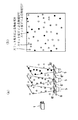
そして、図1(a) に示す如く光源5の照射面にスリット61を形成した金属等のスリット板6を配置し、該スリット61から照射されるシート状の光によって雨片や雪片を照明することにより、シート状の光によって照明された雨片や雪片が図1(b) に示すような撮影画像が撮影手段1より得られる。なお、図13(A)は従来の照明方法により降雨雪片を撮影した画像の写真であり、(B)はシート状の光により降雨雪片を撮影した画像の写真である。
【0026】
このように写し出された奥行き情報が重畳されていない撮影画像の降雨雪成分から前記した画像処理装置を利用することにより、正確なる降雨雪の量、強度、方向を求めることができるものである。
【0027】
次に、第2の実施の形態を図2、図3と共に説明する。
前記した第1の実施の形態にあっては、1つの光源5と、該光源5の照射面に1枚のスリット板6を配置した場合について説明したが、この実施の形態の場合にあっては、奥行き情報を軽減してしまっているために、空間的情報が減少してしまい精度の高い降雨雪情報を得ることができない。
【0028】
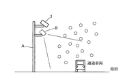
そこで、第2の実施の形態にあっては、空間的情報を得るようにするために3つの異なる輝度の光源5と、該各光源5毎にスリット板6〜6″を配置した場合である。この実施の形態のようにシート状の光をいくつも重ねることにより、図2(a) に示すように奥行き情報を捕らえることができる。すなわち、画像中には、図2(b) のようにある断面毎に輝度の異なった降雨片や降雪片が写し出される。
【0029】
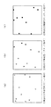
この結果、図3(a) 〜(c) に示す各輝度毎に分別して降雨雪成分を抽出できる。従って、それぞれから得られた情報(降雨雪量、強度、方向)を、規格化して扱うことにより、前記した画像処理装置を利用しても空間的な精度の高い降雨雪の量、強度、方向を求めることができるものである。
【0030】
次に、第3の実施の形態を図4、図5と共に説明する。
前記した第2の実施の形態は、光源5として白色光照明を用いた場合について説明したが、このような白色光照明の場合には、一断面のみを抽出しようとしても既設の照明がテレビカメラの近傍で強度が高いものであれば、その影響を受けることとなり、結果的に奥行き方向の重畳という問題が発生する。
【0031】
そこで、第3の実施の形態にあっては、前記第2の実施の形態における3つの光源5から照射される色を異なる色にしたり、あるいはスリット61に異なる色のフィルタを取付ける等して降雨雪に対して3色の光で照明するようにした。
【0032】
この実施の形態にあっても、図3(b) に示すように画像中には既存照明の影響による降雨雪片が重畳する。しかし、3色の異なる色に照明されているために、図5(a) 〜(c) に示すように、各色毎に色分別して降雨雪成分を抽出することができる。
【0033】
従って、分別された情報(降雨雪量、強度、方向)を、規格化して扱うことにより、前記した画像処理装置を利用しても空間的な精度の高い降雨雪の量、強度、方向を求めることができるものである。図14は1つのシート状の光を赤色とした場合の写真である。
【0034】
なお、前記した実施の形態にあっては、光源5およびスリット板6を1つまたは3つの場合について説明したが、第2の実施の形態の場合には1つの光源5に対して複数のスリット61が形成されたスリット板6を利用してもよく、また、光源5およびスリット板6は3つに限定されるものではなく、空間的な精度を高くする場合には3つ以上配置すればよい。
【0035】
さらに、前記した実施の形態にあっては、光源5を撮影手段1におけるテレビカメラの下側に配置した場合について説明したが、図6に示すように上側、あるいは左右の何れかの方向に配置してもよく、また、図7に示すようにテレビカメラの近傍で、かつ、テレビカメラを軸とした円周方向に配置してもよい。
【0036】
また、シート状の光を出す光源としては、実施の形態のように光源とスリット板を用いる必要はなく、指向性の高いLEDを一列に並べた光源や、ビームを絞ったレーザー光などを扇状に高速掃引する光源などを用いても同様にシート状の光を発生させることが可能である。
【0037】
さらに、前記した実施の形態における説明は、特に、夜間時における降雨雪の状況を検出する場合についての説明であるが、色光(例えば、赤色)のシート状の光を用いることで、昼間時において降雨雪を判別しにくい環境であっても検出が可能となる。
【0038】
【発明の効果】
本発明は前記したように、シート状の光を降雨雪片に照射し、該照射により照明された降雨雪片の画像から降雨雪の量、強度、方向を求めるようにしたので、奥行き情報が重畳されることなく降雨雪片を一意に扱うことが可能となり、従って正確な降雨雪成分の移動ベクトルを求めることができる。
【0039】
また、シート状の光を複数個とすることにより、断面から空間的に情報が拡張され、より正確な降雨雪情報を検出することができ、しかも、前記複数のシート状の光の色を異ならしめることにより、既存照明の影響を受けることなく降雨雪成分を高い精度で抽出することができる等の効果を有するものである。
【図面の簡単な説明】
【図1】 本発明に係る降雨雪状況検出方法およびその装置による第1の実施の形態を示し、(a)は撮影状態を示す斜視図、(b) は撮影された画像である。
【図2】 第2の実施の形態を示し、(a) は撮影状態を示す斜視図、(b) は撮影された画像である。
【図3】 同上のシート状の光毎に撮影された画像である。
【図4】 第3の実施の形態を示し、(a) は撮影状態を示す斜視図、(b) は撮影された画像である。
【図5】 同上のシート状の光毎に撮影された画像である。
【図6】 斜め方向から見た光源5の配置位置の例を示す説明図である。
【図7】 正面から見た光源5の配置位置の例を示す説明図である。
【図8】 従来の照明方法を示す説明図である。
【図9】 画像処理装置のブロック図である。
【図10】 処理動作を示すフローチャートである。
【図11】 従来の照明方法で撮影された降雨雪片を示し、(a) は撮影状態を示す斜視図、(b) は撮影された画像である。
【図12】 同じく従来の照明方法で撮影された降雨雪片を示し、(a) は撮影状態を示す斜視図、(b) は撮影された画像である。
【図13】 (A)は従来の照明方法で撮影された降雨雪片の写真、(B)はシート状の光により撮影された写真である。
【図14】 シート状の赤色光により撮影された降雨雪片の写真である。
【符号の説明】
C 画像処理装置
5 光源
6 スリット板
61 スリット[0001]
BACKGROUND OF THE INVENTION
The present invention mainly relates to a rain / snow condition detection method and apparatus for automatically detecting the amount of rainfall and the amount of snowfall using an imaging means such as a television camera.
[0002]
[Prior art]
Conventionally, as a method for detecting rain or snow conditions falling on an automobile road at night, as shown in FIG. 8, a column A is erected on the shoulder of the vehicle road, and a TV camera or the like is provided above the column A. The
[0003]
Next, the image processing apparatus will be described. This image processing apparatus C is disclosed in Japanese Patent Application No. 10-031154 filed by the applicant company. Hereinafter, an example of the image processing apparatus C will be described with reference to FIGS.
[0004]
The above-mentioned Japanese Patent Application No. 10-031154 discloses three embodiments, namely, a sequential difference method, a dynamic difference processing method, and a Nyquist component extraction method for the extraction of rain and snow components. Three embodiments will be described as one.
[0005]
By the way, the sequential difference method is a method of extracting only a moving object (rain and snow) as a time-series positive / negative component from an image by taking a difference between two images that are temporally adjacent to each other. The method is a method of extracting only the moving body from the image by taking the difference between the background image showing only the stationary object and the captured image showing the moving body, and the Nyquist component extraction method is the time By taking the difference between two images that are adjacent to each other, only a moving object (rain and snow) from the image is subjected to a frequency filter with one of the positive and negative Nyquist components of a pair of Nyquist components having positive and negative polarities in time series. In this method, only a moving object is extracted by calculating a vector connecting between the centroids of the extracted Nyquist components.
[0006]
Hereinafter, the image processing apparatus C for evaluating the rain / snow condition will be described.
1 is a photographing means for outputting image data obtained by capturing a rain / snow detection target area as a digital signal, 2 is an image for storing a frame image composed of a digital signal, and extracting a rain / snow component from a difference of the stored time-series image data. Processing means 3 is an image analysis means for identifying individual rain and snow components and calculating a movement vector, and 4 is an evaluation of any of quantity, intensity and direction based on the calculated number, length and direction of the movement vector. It is a rain and snow evaluation section.
[0007]
Next, details of each means will be described.
The photographing means 1 includes a
[0008]
The image processing means 2 includes a rain / snow
[0009]
In the above-described sequential difference method and Nyquist component extraction method, the image analysis means 3 includes a movement
[0010]
In the above description, when evaluating the conditions of rain and snow on the road where vehicles and pedestrians come and go, in addition to snowflakes and raindrops, traveling vehicles and pedestrians are also extracted as moving components. The area threshold
[0011]
Next, the processing operation of the image processing apparatus C in FIG. 9 will be described with reference to the flowchart in FIG.
The video signal of the rain / snow detection target area photographed by the
[0012]
As described above, when detecting rain and snow conditions in places where vehicles and people cannot pass at all, there are no cases where vehicles or pedestrians are shown on the screen, but when the shooting location is a road, etc. The vehicle running on the screen is also extracted as a moving component. Therefore, in such a case, it is determined in the next area
[0013]
Next, the movement
[0014]
The rain /
[0015]
[Problems to be solved by the invention]
By the way, in the actual image projected by the photographing means 1, the rain / snow component having the depth as seen from the
[0016]
In the rain / snow condition of FIG. 11 (a), the captured image is as shown in FIG. 11 (b) due to the depth, that is, the actual captured image of the rain snowflakes a, b, c Each rain snowflake in Fig. 11 (b) becomes a, b, and c in FIG. 11 (b), and the data is handled two-dimensionally even if the actual size and speed of each rain snowflake are the same. As if it were a different size and speed.
[0017]
In addition, in the rain / snow condition of FIG. 12 (a), the photographed image is as shown in FIG. 12 (b) because of the depth, that is, the photograph is taken for each actual rain snowflake (i), (b), (c). Each rain snowflake on the image becomes a, b, and c in Fig. 11 (b), and even if the actual size and speed of each rain snowflake are different, the data is handled in two dimensions. It looks as if each rainfall snowflake is the same size and speed.
[0018]
Therefore, it is difficult to uniquely handle the snow snowflake in the image data in which the depth information is superimposed, and it is difficult to accurately determine the amount, intensity, direction, etc. of the rain snow calculated from the movement vector obtained from the image. there were.
[0019]
The present invention is intended to St. solve the problems described above, it is an object by performing a lighting sheet, can be extracted rain snow components not superimposed depth information, also a sheet-like By overlaying multiple lights, information can be expanded spatially from the cross-section, and more accurate rainfall and snow information can be extracted. In addition, by changing the brightness of sheet- like lighting or using color lighting, existing lighting can be obtained. It is an object of the present invention to provide a method and an apparatus for detecting a rain / snow condition at night when accurate snow / snow information can be extracted without being affected by the rain.
[0020]
[Means for Solving the Problems]
The rain / snow condition detection method of the present invention is intended to achieve the above-mentioned object, and the method according to
[0021]
According to another aspect of the present invention, there is provided a television camera that captures an image of rain snowflakes illuminated by the sheet-like light and at least two or more light sources that emit light having different brightness or color of the sheet-like light. And an image processing apparatus that extracts any of the amount, intensity, and direction of rain and snow from the image obtained by the imaging means.
[0022]
DETAILED DESCRIPTION OF THE INVENTION
A first embodiment of a rain / snow condition detection method and apparatus according to the present invention will be described below with reference to FIG. In addition, the same code | symbol as the past shows the same member, and description is abbreviate | omitted. Since the
[0025]
Then, as shown in FIG. 1 (a), a
[0026]
By using the image processing apparatus described above from the rain / snow component of the photographed image on which the depth information thus projected is not superimposed, the exact amount, intensity and direction of the rain / snow can be obtained.
[0027]
Next, a second embodiment will be described with reference to FIGS.
In the first embodiment described above, the case where one
[0028]
Therefore, in the second embodiment, in order to obtain spatial information, the
[0029]
As a result, the rain / snow component can be extracted by classification for each luminance shown in FIGS. 3 (a) to 3 (c). Therefore, the information (rainfall amount, intensity, direction) obtained from each is standardized and handled, so that the amount, intensity, direction of the snowfall with high spatial accuracy even when using the image processing apparatus described above. Can be obtained.
[0030]
Next, a third embodiment will be described with reference to FIGS.
In the above-described second embodiment, the case where white light illumination is used as the
[0031]
Therefore, in the third embodiment, it is rained by changing the colors emitted from the three
[0032]
Even in this embodiment, as shown in FIG. 3B, rain snowflakes due to the influence of existing illumination are superimposed on the image. However, since the three different colors are illuminated, as shown in FIGS. 5 (a) to 5 (c), it is possible to extract rain and snow components by color separation for each color.
[0033]
Therefore, by standardizing the classified information (rainfall amount, intensity, direction), the amount, intensity, and direction of snowfall with high spatial accuracy can be obtained even if the above-described image processing apparatus is used. It is something that can be done. FIG. 14 is a photograph when one sheet-like light is red.
[0034]
In the above-described embodiment, one or three
[0035]
Further, in the above-described embodiment, the case where the
[0036]
In addition, as a light source that emits sheet- like light, it is not necessary to use a light source and a slit plate as in the embodiment, and a light source in which LEDs with high directivity are arranged in a row or a laser beam with a narrowed beam is fan-shaped. Even if a light source that sweeps at a high speed is used, sheet- like light can be generated in the same manner.
[0037]
Further, the description in the above-described embodiment is a description in particular regarding the case of detecting the state of rain and snow at night, but by using colored light (for example, red) sheet- like light, Detection is possible even in an environment where it is difficult to discriminate between rain and snow.
[0038]
【The invention's effect】
As described above, the present invention irradiates the snow flakes with sheet- like light, and obtains the amount, intensity, and direction of the rain snow from the image of the rain flakes illuminated by the irradiation, so the depth information is superimposed. Therefore, it is possible to handle a snowfall piece without any problem, so that an accurate movement vector of the snowfall component can be obtained.
[0039]
In addition, by using a plurality of sheet- like lights, information can be spatially expanded from the cross section, more accurate rain / snow information can be detected, and the colors of the plurality of sheet-like lights can be different. By tightening, the rain and snow components can be extracted with high accuracy without being affected by existing lighting.
[Brief description of the drawings]
1A and 1B show a first embodiment of a rain / snow condition detection method and apparatus according to the present invention, wherein FIG. 1A is a perspective view showing a photographing state, and FIG. 1B is a photographed image;
FIG. 2 shows a second embodiment, (a) is a perspective view showing a shooting state, and (b) is a shot image.
FIG. 3 is an image taken for each sheet-like light.
4A and 4B show a third embodiment, in which FIG. 4A is a perspective view showing a shooting state, and FIG. 4B is a shot image.
FIG. 5 is an image taken for each sheet-like light.
FIG. 6 is an explanatory diagram showing an example of an arrangement position of the
FIG. 7 is an explanatory diagram showing an example of an arrangement position of the
FIG. 8 is an explanatory diagram showing a conventional illumination method.
FIG. 9 is a block diagram of an image processing apparatus.
FIG. 10 is a flowchart showing a processing operation.
FIGS. 11A and 11B show rain snowflakes photographed by a conventional illumination method, FIG. 11A is a perspective view showing a photographing state, and FIG. 11B is a photographed image.
FIGS. 12A and 12B show rain snowflakes similarly photographed by a conventional illumination method, FIG. 12A is a perspective view showing a photographing state, and FIG. 12B is a photographed image.
FIGS. 13A and 13B are photographs of rainfall snowflakes taken by a conventional lighting method, and FIGS. 13B and B are photographs taken by sheet-like light.
FIG. 14 is a photograph of rain snowflakes taken with sheet-like red light .
[Explanation of symbols]
C
Claims (2)
Priority Applications (1)
| Application Number | Priority Date | Filing Date | Title |
|---|---|---|---|
| JP36845998A JP4064556B2 (en) | 1998-12-10 | 1998-12-10 | Rain and snow condition detection method and apparatus |
Applications Claiming Priority (1)
| Application Number | Priority Date | Filing Date | Title |
|---|---|---|---|
| JP36845998A JP4064556B2 (en) | 1998-12-10 | 1998-12-10 | Rain and snow condition detection method and apparatus |
Publications (2)
| Publication Number | Publication Date |
|---|---|
| JP2000180563A JP2000180563A (en) | 2000-06-30 |
| JP4064556B2 true JP4064556B2 (en) | 2008-03-19 |
Family
ID=18491877
Family Applications (1)
| Application Number | Title | Priority Date | Filing Date |
|---|---|---|---|
| JP36845998A Expired - Fee Related JP4064556B2 (en) | 1998-12-10 | 1998-12-10 | Rain and snow condition detection method and apparatus |
Country Status (1)
| Country | Link |
|---|---|
| JP (1) | JP4064556B2 (en) |
Families Citing this family (9)
| Publication number | Priority date | Publication date | Assignee | Title |
|---|---|---|---|---|
| JP4430659B2 (en) * | 2006-12-25 | 2010-03-10 | シーシーエス株式会社 | Weather measurement equipment |
| JP4505509B2 (en) * | 2008-01-16 | 2010-07-21 | 日本電信電話株式会社 | Weather information detection method, weather information detection apparatus, and weather information detection program |
| JP5055476B2 (en) * | 2009-11-18 | 2012-10-24 | シーシーエス株式会社 | Weather measurement equipment |
| CN102183801B (en) * | 2011-03-18 | 2012-06-13 | 中国气象科学研究院 | System for automatically observing precipitation phenomenon based on digital shooting |
| KR20140006463A (en) * | 2012-07-05 | 2014-01-16 | 현대모비스 주식회사 | Method and apparatus for recognizing lane |
| JP2018048900A (en) * | 2016-09-21 | 2018-03-29 | サクサ株式会社 | Precipitation detector |
| CN106772700B (en) * | 2017-02-21 | 2023-12-19 | 中国水利水电科学研究院 | Regional rainfall uniformity measuring system and method based on close-range photogrammetry principle |
| CN106872406B (en) * | 2017-02-21 | 2023-12-19 | 中国水利水电科学研究院 | Regional rainfall uniformity measuring system and method based on digital image processing technology |
| CN116648921A (en) * | 2020-08-21 | 2023-08-25 | 株式会社小糸制作所 | In-vehicle sensing system and door control camera |
-
1998
- 1998-12-10 JP JP36845998A patent/JP4064556B2/en not_active Expired - Fee Related
Also Published As
| Publication number | Publication date |
|---|---|
| JP2000180563A (en) | 2000-06-30 |
Similar Documents
| Publication | Publication Date | Title |
|---|---|---|
| CN104512411B (en) | Vehicle control system and imaging sensor | |
| EP2448251B1 (en) | Bundling night vision and other driver assistance systems (DAS) using near infra red (NIR) illumination and a rolling shutter | |
| EP3412511B1 (en) | Bundling of driver assistance systems | |
| WO2010137563A1 (en) | Image processing apparatus | |
| US10482347B2 (en) | Inspection of the contoured surface of the undercarriage of a motor vehicle | |
| JP4977923B2 (en) | Active vehicle visibility assist device and vehicle visibility assist method | |
| KR20070005553A (en) | Imaging system | |
| GB2510833A (en) | A road marking analyser and a method of analysing of road markings | |
| JP2009201064A (en) | Method and apparatus for specifying related region, and method and apparatus for recognizing image | |
| KR20000071087A (en) | Outdoor range finder | |
| KR20180019189A (en) | Systems and methods for processing streamed video images to compensate for the flicker of amplitude-modulated light | |
| CN109409186A (en) | Driver assistance system and method for object detection and notice | |
| CN108197523A (en) | Vehicle detection at night method and system based on image conversion and profile neighborhood difference | |
| JP2009017157A (en) | Image processor, method and program | |
| JP4064556B2 (en) | Rain and snow condition detection method and apparatus | |
| JP4927647B2 (en) | Vehicle periphery monitoring device | |
| KR20080004833A (en) | Apparatus and method for detecting a navigation vehicle in day and night according to luminous state | |
| KR102185100B1 (en) | Safety Management System on a Crosswalk for Pedestrian and its Method | |
| JP3570198B2 (en) | Image processing method and apparatus | |
| JP2006259885A (en) | Method of recognizing signboard and sign using color image | |
| JP2002260165A (en) | Vehicle monitoring system | |
| JP2011227657A (en) | Device for monitoring periphery of vehicle | |
| JP4887540B2 (en) | Vehicle periphery monitoring device, vehicle, vehicle periphery monitoring program, and vehicle periphery monitoring method | |
| JP2004086417A (en) | Method and device for detecting pedestrian on zebra crossing | |
| JP2006252363A (en) | Detector for object around vehicle, and method of detecting object around vehicle |
Legal Events
| Date | Code | Title | Description |
|---|---|---|---|
| A621 | Written request for application examination |
Free format text: JAPANESE INTERMEDIATE CODE: A621 Effective date: 20051125 |
|
| A977 | Report on retrieval |
Free format text: JAPANESE INTERMEDIATE CODE: A971007 Effective date: 20070531 |
|
| A131 | Notification of reasons for refusal |
Free format text: JAPANESE INTERMEDIATE CODE: A131 Effective date: 20070703 |
|
| A521 | Written amendment |
Free format text: JAPANESE INTERMEDIATE CODE: A523 Effective date: 20070831 |
|
| TRDD | Decision of grant or rejection written | ||
| A01 | Written decision to grant a patent or to grant a registration (utility model) |
Free format text: JAPANESE INTERMEDIATE CODE: A01 Effective date: 20071211 |
|
| A61 | First payment of annual fees (during grant procedure) |
Free format text: JAPANESE INTERMEDIATE CODE: A61 Effective date: 20071227 |
|
| R150 | Certificate of patent or registration of utility model |
Free format text: JAPANESE INTERMEDIATE CODE: R150 |
|
| FPAY | Renewal fee payment (event date is renewal date of database) |
Free format text: PAYMENT UNTIL: 20110111 Year of fee payment: 3 |
|
| FPAY | Renewal fee payment (event date is renewal date of database) |
Free format text: PAYMENT UNTIL: 20120111 Year of fee payment: 4 |
|
| FPAY | Renewal fee payment (event date is renewal date of database) |
Free format text: PAYMENT UNTIL: 20140111 Year of fee payment: 6 |
|
| R250 | Receipt of annual fees |
Free format text: JAPANESE INTERMEDIATE CODE: R250 |
|
| LAPS | Cancellation because of no payment of annual fees |