JP4063786B2 - Multicast packet distribution system - Google Patents
Multicast packet distribution system Download PDFInfo
- Publication number
- JP4063786B2 JP4063786B2 JP2004090148A JP2004090148A JP4063786B2 JP 4063786 B2 JP4063786 B2 JP 4063786B2 JP 2004090148 A JP2004090148 A JP 2004090148A JP 2004090148 A JP2004090148 A JP 2004090148A JP 4063786 B2 JP4063786 B2 JP 4063786B2
- Authority
- JP
- Japan
- Prior art keywords
- multicast
- interface
- address
- upstream
- upstream interface
- Prior art date
- Legal status (The legal status is an assumption and is not a legal conclusion. Google has not performed a legal analysis and makes no representation as to the accuracy of the status listed.)
- Expired - Fee Related
Links
Images


Landscapes
- Data Exchanges In Wide-Area Networks (AREA)
Description
本発明は、マルチキャストパケット配信システムに関し、特に、複数の顧客が、複数の事業者が配信しているストリーミングを、複数の事業者から同時に受信可能にしたマルチキャストパケット配信システムに関する。 The present invention relates to a multicast packet distribution system, and more particularly to a multicast packet distribution system in which a plurality of customers can simultaneously receive streaming distributed by a plurality of operators from a plurality of operators.
ADSLやCATV等の高速通信が普及しつつある現在、ストリーミング配信は、ますます重要なコンテンツ配信手段になると考えられ、今後、ADSLマルチキャストプロキシルータやブロードバンドルータは、マルチキャスト(Multicast)に対応することが必須になると思われる。ここに、ストリーミング配信とは、データを読み出しながらその場で再生していく情報配信の総称であり、マルチキャストとは、同じデータを複数の宛先アドレスに配布することをいう。(特許文献1、特許文献2、参照)
As high-speed communications such as ADSL and CATV are spreading, streaming delivery is considered to become an increasingly important content delivery method. In the future, ADSL multicast proxy routers and broadband routers will be able to support multicast (Multicast). It seems to be essential. Here, streaming distribution is a general term for information distribution in which data is read and reproduced on the spot, and multicast refers to distributing the same data to a plurality of destination addresses. (See
このマルチキャストに対応するのに必要となる技術が、マルチキャストのグループを制御するためのプロトコルであるIGMP/MLD(Internet Group Management Protocol/Multicast Listener Discovery)(後述)である。このIGMP/MLDの実装の容易さ等を考えると、ADSLモデムやブロードバンドルータの多くは、IGMP/MLDプロキシ(代理)機能を実装することになる。 A technique required to support this multicast is IGMP / MLD (Internet Group Management Protocol / Multicast Listener Discovery) (described later), which is a protocol for controlling a multicast group. Considering the ease of implementation of this IGMP / MLD, many ADSL modems and broadband routers implement the IGMP / MLD proxy (proxy) function.
ここで、従来のIGMP/MLDプロキシ機能を用いたIPマルチキャストパケット配信システム(以下、IPマルチキャストパケット配信システムと記す)100について、図7を参照しつつ説明する。なお、この種のIGMP/MLDプロキシ機能を用いたIPマルチキャストパケット配信システムについては、例えば、特許文献3−5に記載されている。
ここで、図7のシステム構成は、後述する本発明の実施形態のシステム構成と殆ど同じであるので(マルチキャストプロキシルータの構成および機能のみが異なる)、システム構成の詳細説明は、実施形態において行う。
Here, a conventional IP multicast packet distribution system (hereinafter referred to as an IP multicast packet distribution system) 100 using the IGMP / MLD proxy function will be described with reference to FIG. An IP multicast packet distribution system using this kind of IGMP / MLD proxy function is described in, for example, Patent Documents 3-5.
Here, the system configuration of FIG. 7 is almost the same as the system configuration of the embodiment of the present invention to be described later (only the configuration and functions of the multicast proxy router are different), so the detailed description of the system configuration will be given in the embodiment. .
第1インターネットサービスプロバイダ(事業者A)130a,第2インターネットサービスプロバイダ(事業者B)130bのそれぞれのネットワークは、インターネット140に接続されている。第1,第2インターネットサービスプロバイダ130a,130bは、それぞれ第1,第2マルチキャストルータ131a,131bと、第1,第2マルチキャストサーバ132a,132bを備えている。第1,第2マルチキャストルータ131a,131bは、マルチキャストプロキシルータ(IGMP/MLDプロキシルータ)110の第1,第2アップストリームインタフェース111a,111bに接続されている。
The networks of the first Internet service provider (operator A) 130a and the second Internet service provider (operator B) 130b are connected to the Internet 140. The first and second
マルチキャストプロキシルータ110の第1,第2ダウンストリームインタフェース112a,112bは、それぞれ第1マルチキャストクライアント端末(顧客C1)121aと、第2マルチキャストクライアント端末(顧客C2)121bに接続されている。
The first and second
ここに、アップストリームインタフェースとは、上流側(マルチキャストルータ)に接続しているインタフェースをいい、ダウンストリームインタフェースとは、アップストリームインタフェースとは逆側(下流側)のインタフェースをいう。 Here, the upstream interface refers to an interface connected to the upstream side (multicast router), and the downstream interface refers to an interface on the opposite side (downstream side) from the upstream interface.
ここで、IPマルチキャストパケット配信システム100を構成する要素(マルチキャストサーバ等)の基本的機能を、図8,図9を参照しつつ説明する。
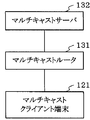
図8は、マルチキャストサーバとマルチキャストルータとマルチキャストクライアント端末との関係を、単純化して示すシステム構成図である。
図9は、図8の構成に、マルチキャストプロキシルータ(IGMP/MLDプロキシルータ)を追加した場合のシステム構成図である。
Here, basic functions of elements (such as a multicast server) constituting the IP multicast
FIG. 8 is a system configuration diagram showing the relationship among a multicast server, a multicast router, and a multicast client terminal in a simplified manner.
FIG. 9 is a system configuration diagram when a multicast proxy router (IGMP / MLD proxy router) is added to the configuration of FIG.
図8に示すように、ストリーミング配信サーバ等のマルチキャストサーバ132(132a,132b)は、マルチキャストパケットを送信し続ける。この状態では、マルチキャストルータ131(131a,131b)は、マルチキャストパケットを受信したインタフェース以外のインタフェースへマルチキャストパケットを転送しない。
即ち、マルチキャストルータ131の 上流側インタフェースで受信したマルチキャストパケットを、下流側インタフェースに転送しない。
As shown in FIG. 8, the multicast server 132 (132a, 132b) such as a streaming distribution server continues to transmit multicast packets. In this state, the multicast router 131 (131a, 131b) does not transfer the multicast packet to an interface other than the interface that has received the multicast packet.
That is, the multicast packet received by the upstream interface of the
マルチキャストクライアント端末121(121a,121b)が、マルチキャストサーバ132からのマルチキャストパケットを受信したい場合は、マルチキャストルータ131宛にマルチキャストグループ「X.X.X.X」を受信したいというメッセージ(受信要求メッセージ)を送信する。ここで、「X.X.X.X」は、マルチキャストグループのアドレスである。
When the multicast client terminal 121 (121a, 121b) wishes to receive a multicast packet from the
マルチキャストルータ131は、前記受信要求メッセージを受信して、はじめてマルチキャストサーバ132からのマルチキャストパケットを、下流側へ転送する。
このメッセージ送信に使用するプロトコルが、前記のIGMP/MLDである。
なお、実際のネットワークでは、複数(多数)のサーバ,ルータ,クライアント端末が接続されている。
The
The protocol used for this message transmission is the IGMP / MLD.
In an actual network, a plurality of (many) servers, routers, and client terminals are connected.
複数のサーバ,ルータ,クライアント端末が接続された場合には、マルチキャストルータ131が管理しなければならない情報(マルチキャストグループのデータ等)が、増えてくる。
なお、基本的にマルチキャストサーバ132は、マルチキャストクライアント端末121の存在の有無に拘わらず、マルチキャストパケットを送信し続ける。
When a plurality of servers, routers, and client terminals are connected, information (multicast group data, etc.) that the
Basically, the
次に、図9を参照しつつ、マルチキャストプロキシルータ(IGMP/MLDプロキシルータ)110の説明をする。
マルチキャストプロキシルータ110は、マルチキャストクライアント端末121からの「X.X.X.X」という受信要求メッセージを受信して、はじめてマルチキャストプロキシルータ110としての動作を開始する。
Next, the multicast proxy router (IGMP / MLD proxy router) 110 will be described with reference to FIG.
The
図9に示したネットワーク(システム構成)で、マルチキャストクライアント端末121が「X.X.X.X」の受信要求メッセージを送信していない状態では、マルチキャストプロキシルータ110が、マルチキャストパケットに関する情報を管理する必要はない。
In the network (system configuration) illustrated in FIG. 9, when the
マルチキャストクライアント端末121からの「X.X.X.X」の受信要求メッセージを受信したマルチキャストプロキシルータ110は、「X.X.X.X」の受信要求メッセージをマルチキャストルータ131へ送信する。
このことが、プロキシ(代理)といわれる所以であり、マルチキャストプロキシルータ110のアップストリームインタフェース111では、マルチキャストクライアント端末121のような動作を行う。
The
This is the reason why it is called a proxy, and the upstream interface 111 of the
このメッセージを受信したマルチキャストルータ131は、この「X.X.X.X」のマルチキャストグループのマルチキャストパケットだけを、下流側へ転送する。
マルチキャストプロキシルータ110は、このマルチキャストパケットを受信し、マルチキャストクライアント端末121へ転送する。
Receiving this message, the
The
よって、マルチキャストプロキシルータ110は、マルチキャストクライアント端末121が受信したい「X.X.X.X」というマルチキャストグループだけを管理すれば良いことになる。
このように、マルチキャストプロキシルータ110を使用すれば、管理しなければならない情報が少なくて済む。
Therefore, the
Thus, if the
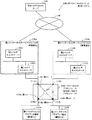
しかしながら、従来のIGMP/MLDプロキシ機能を実装しているマルチキャストプロキシルータ110は、上位ルータ側に対し、一組の論理インタフェース(アップストリームインタフェースとダウンストリームインタフェース)のみを動作させている。即ち、図7に示すように、マルチキャストプロキシルータ110は、複数の論理インタフェースを備えている場合でも、複数の論理インタフェースを同時に動作させることができない。
However, the
つまり、第1マルチキャストクライアント端末(顧客C1)121aと第2マルチキャストクライアント端末(顧客C2)が、それぞれ第1ルート113aと第2ルート113bで動作している場合には(実線で示す)、第3ルート114aと第4ルート114bを同時に動作させることはできない(点線に「×」印を付して示す)。
なお、複数の論理インタフェースのうち、いずれの論理インタフェースを動作させるかは、マルチキャストクライアント端末側から選択可能となっている。
That is, when the first multicast client terminal (customer C1) 121a and the second multicast client terminal (customer C2) are operating on the first route 113a and the second route 113b, respectively (indicated by a solid line), the third The route 114a and the fourth route 114b cannot be operated at the same time (shown with a “x” mark on the dotted line).
Note that which of the plurality of logical interfaces is to be operated can be selected from the multicast client terminal side.
このため、事業者Aと事業者Bが、自分の顧客にだけストリーミングコンテンツを配信するようなサービスを行っている場合、事業者Aと事業者Bの共通の顧客C1と顧客C2が、事業者Aと事業者Bが配信しているストリーミングを、両方から同時に受信することはできない。 For this reason, when the business operator A and the business operator B perform a service that delivers streaming content only to their own customers, the common customer C1 and customer C2 of the business operator A and the business operator B are the business operators. Streaming distributed by A and operator B cannot be received simultaneously from both.
本発明は、上記の問題を解決すべくなされたものであり、複数の顧客が、複数の事業者が配信しているストリーミングを、複数の事業者から同時に受信可能としたマルチキャストパケット配信システムの提供を目的とする。 The present invention has been made to solve the above problem, and provides a multicast packet distribution system in which a plurality of customers can simultaneously receive streaming distributed by a plurality of operators from a plurality of operators. With the goal.
この目的を達成するために本発明のマルチキャストパケット配信システムは、上位ネットワーク(図1のインターネット140)に接続された、複数の下位ネットワークを構成するそれぞれのプロバイダ(第1,第2インターネットサービスプロバイダ130a,130b(事業者A,事業者B))が、それぞれのプロバイダ側のマルチキャストルータ(第1,第2マルチキャストルータ131a,131b)および複数の端末(第1,第2マルチキャストクライアント端末121a,121b(顧客C1,顧客C2))が接続されたマルチキャストプロキシルータ(20)を介して、コンテンツを複数の端末にマルチキャストパケットで配信するマルチキャストパケット配信システムにおいて、
マルチキャストプロキシルータが備える複数の上流側インタフェース上(第1,第2アップストリームインタフェース111a,111b上)のマルチキャストパケットを、マルチキャストプロキシルータが備える複数の下流側インタフェース(第1,第2ダウンストリームインタフェース112a,112b)に、同時に配信する同時配信手段(図3のデータベース21,設定テーブル22,重複テーブル23)を備えた構成としてある。
In order to achieve this object, the multicast packet distribution system of the present invention is configured so that each provider (first and second
Multicast packets on a plurality of upstream interfaces (on the first and second
以上の構成を図示すると、例えば図1,図3に示すようになる。このようにすれば、事業者Aからのマルチキャストパケットは、上流側インタフェース111aを介して二つの下流側インタフェース112a,112bに同時に配信されるので、顧客C1と顧客C2とは、同時に事業者Aからのマルチキャストパケットを受信できる(実線の第1ルート20aと第2ルート20bで示す)。
The above configuration is illustrated in FIGS. 1 and 3, for example. In this way, since the multicast packet from the operator A is simultaneously delivered to the two
また、事業者Bからのマルチキャストパケットは、上流側インタフェース111bを介して二つの下流側インタフェース112a,112bに同時に配信されるので、顧客C1と顧客C2とは、同時に事業者Bからのマルチキャストパケットを受信できる(実線の第3ルート20cと第4ルート20dで示す)。
即ち、複数の顧客(C1とC2)は、複数の事業者(AとB)が配信しているストリーミング(マルチキャストパケット)を、同時に受信可能とすることができる。
Further, since the multicast packet from the operator B is simultaneously distributed to the two
That is, a plurality of customers (C1 and C2) can simultaneously receive streaming (multicast packets) distributed by a plurality of operators (A and B).
また、本発明のマルチキャストパケット配信システムは、マルチキャストプロキシルータが備える複数の下流側インタフェース上のマルチキャストパケットを、マルチキャストプロキシルータが備える複数の上流側インタフェースに、同時に配信可能にした構成としてある。 Further, the multicast packet delivery system of the present invention, the multicast packets on the plurality of downstream-side interface provided for the multicast proxy router, the plurality of upstream interfaces multicast proxy router comprises, is a structure in which the deliverable simultaneously.
以上の構成を図示すると、例えば図1,図3に示すようになる。このようにすれば、顧客C1からのマルチキャストパケットは、下流側インタフェース112aを介して二つの上流側インタフェース111a,111bに同時に配信されるので、事業者Aと事業者Bとは、同時に顧客C1からのマルチキャストパケットを受信できる(実線の第1ルート20aと第3ルート20cで示す。但し、矢印方向は逆である)。
The above configuration is illustrated in FIGS. 1 and 3, for example. In this way, since the multicast packet from the customer C1 is simultaneously delivered to the two
また、顧客C2からのマルチキャストパケットは、下流側インタフェース112bを介して二つの上流側インタフェース111a,111bに同時に配信されるので、事業者Aと事業者Bとは、同時に顧客C2からのマルチキャストパケットを受信できる(実線の第2ルート20bと第4ルート20dで示す.但し、矢印方向は逆である)。
Further, since the multicast packet from the customer C2 is simultaneously delivered to the two
また、本発明のマルチキャストパケット配信システムは、同時配信手段は、少なくともマルチキャストアドレスXのグループが、どのインタフェースで動作しているかの情報を管理するデータベース(図3の21)と、少なくともマルチキャストパケットのマルチキャストアドレスと上流側インタフェースを関連付けるための設定と、端末のIPアドレスと上流側インタフェースを関連付けるための設定と、端末のMACアドレスと上流側インタフェースを関連付けるための設定と、下流側インタフェースと上流側インタフェースを関連付けるための設定と、マルチキャストサーバのIPアドレスと下流側インタフェースを関連付けるための設定とを行う第一の設定手段(設定テーブル22)と、一つのマルチキャストアドレスを複数のインタフェースで使用する場合、重複するエントリはすべて、上流側インタフェースと下流側インタフェースを関連付けるための設定と、マルチキャストサーバのIPアドレスと下流側インタフェースを関連付けるための設定とを行う第二の設定手段(重複テーブル23)とを備えた構成としてある。 Further, the multicast packet delivery system of the present invention, simultaneous delivery means, a group of at least the multicast address X, a database for managing of information running on which interface (21 in FIG. 3), at least the multicast packet Settings for associating the multicast address with the upstream interface, settings for associating the IP address of the terminal with the upstream interface, settings for associating the MAC address of the terminal with the upstream interface, and the downstream interface and the upstream interface A first setting means (setting table 22) for performing a setting for associating the IP address of the multicast server and a setting for associating the downstream interface, and a single multicast address for a plurality of interfaces The second setting means (duplication table) for performing the setting for associating the upstream interface with the downstream interface and the setting for associating the IP address of the multicast server with the downstream interface. 23).
以上の構成を図示すると、例えば図1,図3,図4に示すようになる。上述した同時配信手段が正常に機能するためには、複数の事業者(AとB)と、複数の顧客(C1とC2)との間のルートを設定するために、最小限の各種データを必要とする。
データベース(21)は、少なくともマルチキャストアドレスXのグループが、どのインタフェースで動作しているかの情報を管理する。
The above configuration is illustrated in FIGS. 1, 3, and 4, for example. For simultaneous delivery means described above to function properly, a plurality of carriers between (A and B), in order to set a route between a plurality of customer (C1 and C2), a minimum of various data Need.
The database (21) manages information on which interface at least the group of the multicast address X is operating.
第一の設定手段(設定テーブル22)は、少なくともマルチキャストパケットのマルチキャストアドレスと上流側インタフェースを関連付けるための設定と、端末のIPアドレスと上流側インタフェースを関連付けるための設定と、端末のMACアドレスと上流側インタフェースを関連付けるための設定と、下流側インタフェースと上流側インタフェースを関連付けるための設定と、マルチキャストサーバのIPアドレスと下流側インタフェースを関連付けるための設定とを行う。 The first setting means (setting table 22) includes a setting for associating at least the multicast address of the multicast packet with the upstream interface, a setting for associating the IP address of the terminal with the upstream interface, the MAC address of the terminal and the upstream A setting for associating the downstream interface, a setting for associating the downstream interface with the upstream interface, and a setting for associating the IP address of the multicast server with the downstream interface are performed.
第二の設定手段(重複テーブル23)は、一つのマルチキャストアドレスを複数のインタフェースで使用する場合、重複するエントリはすべて、上流側インタフェースと下流側インタフェースを関連付けるための設定と、マルチキャストサーバのIPアドレスと下流側インタフェースを関連付けるための設定とを行う。 When the second setting means (duplication table 23) uses one multicast address for a plurality of interfaces, all the duplicate entries are set to associate the upstream interface with the downstream interface, and the IP address of the multicast server And setting for associating the downstream interface.
また、本発明のマルチキャストパケット配信システムは、第一の設定手段は、上流側インタフェースがリンクダウンした場合に、他にリンクアップしている上流側インタフェースがある場合には、該リンクアップしている上流側インタフェースを使用する設定を行う構成としてある。
このようにすれば、リンクダウンが発生した場合であっても、事業者側と顧客側との接続性を維持することができる。
Further, in the multicast packet distribution system of the present invention , the first setting means, when the upstream interface is linked down, when there is another upstream interface linked up, is linked up. In this configuration, the upstream interface is set to be used.
In this way, even when a link down occurs, the connectivity between the provider side and the customer side can be maintained.
また、本発明のマルチキャストパケット配信システムは、第一の設定手段は、上流側インタフェースのIPアドレスを解放した場合に、他に使用可能な上流側インタフェースがある場合は、該上流側インタフェースを使用する設定を行う構成としてある。
このようにすれば、上流側インタフェースのIPアドレスを解放した場合であっても、事業者側と顧客側との接続性を維持することができる。
In the multicast packet distribution system of the present invention, when the IP address of the upstream interface is released , the first setting means uses the upstream interface when there is another upstream interface that can be used. It is configured to make settings.
In this way, even when the IP address of the upstream interface is released, the connectivity between the operator side and the customer side can be maintained.
また、本発明のマルチキャストパケット配信システムは、上位ネットワークは、インターネット(140)である構成としてある。
このようにすれば、インターネット上に存在するマルチキャストサーバ(第3マルチキャストサーバ141)と、複数の端末(顧客C1,顧客C2)との間で、下位ネットワークを介して、マルチキャストパケットの送受信を行うことができる。
Further, the multicast packet delivery system of the present invention, the upper level network has a configuration which is the Internet (140).
In this way, multicast packets are transmitted and received between the multicast server (third multicast server 141) existing on the Internet and a plurality of terminals (customer C1, customer C2) via the lower network. Can do.
本発明によれば、マルチキャストパケットを上流側インタフェースに配信する機能を備えたので、複数の顧客が、複数の事業者が配信しているマルチキャストパケットを、同時に受信可能とすることができる。
また、逆に、複数の事業者が、複数の顧客が配信するマルチキャストパケットを、同時に受信可能とすることができる。
According to the present invention, since the multicast packet is distributed to the upstream interface, a plurality of customers can simultaneously receive the multicast packet distributed by a plurality of operators.
Conversely, a plurality of operators can simultaneously receive multicast packets distributed by a plurality of customers.
さらに、複数の事業者と、複数の顧客との間のルートを設定するために、最小限の各種データを備えたので、同時配信手段を正常に機能させることができる。
しかも、設定テーブルは、上流側インタフェースがリンクダウンした場合に、他にリンクアップしている上流側インタフェースがある場合には、該リンクアップしている上流側インタフェースを使用する設定を行う構成としてあるので、リンクダウンが発生した場合であっても、事業者側と顧客側との接続性を維持することができる。
Furthermore, since a minimum amount of various data is provided to set routes between a plurality of businesses and a plurality of customers, the simultaneous distribution means can function normally.
In addition, the setting table is configured to perform settings to use the upstream interface that is linked up when there is another upstream interface that is linked up when the upstream interface is linked down. Therefore, even when link down occurs, the connectivity between the provider side and the customer side can be maintained.
また、設定テーブルは、上流側インタフェースのIPアドレスを解放した場合に、他に使用可能な上流側インタフェースがある場合は、該上流側インタフェースを使用する設定を行う構成としてあるので、上流側インタフェースのIPアドレスを解放した場合であっても、事業者側と顧客側との接続性を維持することができる。 In addition, when the IP address of the upstream interface is released, and there is another upstream interface that can be used, the setting table is configured to use the upstream interface. Even when the IP address is released, the connectivity between the operator side and the customer side can be maintained.
さらに、上位ネットワークは、インターネットである構成としてあるので、インターネット上に存在するマルチキャストサーバと、複数の端末との間で、下位ネットワークを介して、マルチキャストパケットの送受信を行うことができる。 Furthermore, since the upper network is configured to be the Internet, multicast packets can be transmitted / received between a multicast server existing on the Internet and a plurality of terminals via the lower network.
以下、本発明の一実施形態について説明する。
[実施形態]
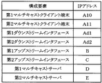
図1は、本実施形態のIPマルチキャストパケット配信システム10のシステム構成図、図2はIPマルチキャストパケット配信システム10を構成するマルチキャストプロキシルータ等の構成要素のIPアドレスの一覧表である。なお、既に概略構成を説明した従来例(図7)と本実施形態(図1)との相違点は、顧客側が備えるマルチキャストプロキシルータ20の構成および機能である。
Hereinafter, an embodiment of the present invention will be described.
[Embodiment]
FIG. 1 is a system configuration diagram of an IP multicast packet distribution system 10 according to the present embodiment, and FIG. 2 is a list of IP addresses of components such as a multicast proxy router that configure the IP multicast packet distribution system 10. The difference between the conventional example (FIG. 7) whose schematic configuration has already been explained and the present embodiment (FIG. 1) is the configuration and function of the
図1,図2に示すように、IGMP/MLDプロキシ機能を実装しているマルチキャストプロキシルータ(IGMP/MLDプロキシルータ)20は、第1アップストリームインタフェース111a、第2アップストリームインタフェース111b、第1ダウンストリームインタフェース112a、第2ダウンストリームインタフェース112bを備えている。
As shown in FIGS. 1 and 2, a multicast proxy router (IGMP / MLD proxy router) 20 that implements an IGMP / MLD proxy function includes a first
マルチキャストプロキシルータ20の第1ダウンストリームインタフェース112a側には、第1マルチキャストクライアント端末121aが接続され、第2ダウンストリームインタフェース112b側には、第2マルチキャストクライアント端末121bが接続されている。
The first
第1アップストリームインタフェース111aは、第1インターネットサービスプロバイダ130a内の第1マルチキャストルータ131aに接続され、第2アップストリームインタフェース111bは、第2インターネットサービスプロバイダ130b内の第2マルチキャストルータ131bに接続されている。
The first
第1マルチキャストサーバ132aは、第1インターネットサービスプロバイダ130aが用意したマルチキャストサーバであり、第1インターネットサービスプロバイダ130aのネットワーク内に設置されている。
第2マルチキャストサーバ132bは、第2インターネットサービスプロバイダ130bが用意したマルチキャストサーバで、第2インターネットサービスプロバイダ130bのネットワーク内に設置されている。
The
The
また、第1インターネットサービスプロバイダ130a、第2インターネットサービスプロバイダ130b以外のネットワーク(インターネット)140に、第3マルチキャストサーバ141が設置されている。
A
図3に示すように、本実施形態のIGMP/MLDプロキシ機能を実装しているマルチキャストプロキシルータ20は、三つの管理テーブルを有している。
第一の管理テーブルは、、受信したIGMPパケット(IPv6の場合は、MLDパケット)の情報を基に作成されるマルチキャストアドレスのデータベース21管理する。マルチキャストプロキシルータ20は、このデータベース21を基にマルチキャストの振り分けを行う。本実施形態では、以降、このデータベース21を、単にデータベース21と呼ぶ。
As shown in FIG. 3, the
The first management table manages the
第二の管理テーブルは、振り分け先の設定を行うテーブル22である。このテーブル22は、ユーザがスタティックに設定するテーブルで、マルチキャストプロキシルータ20は、データベース21に登録されていないIGMPパケットを受信した場合、このテーブル22に従ってデータベース21を作成する。本実施形態では、以降、このテーブルを、設定テーブル22と呼ぶ。
The second management table is a table 22 for setting a distribution destination. This table 22 is a table that is statically set by the user. When the
第三の管理テーブルは、一つのマルチキャストアドレスを、複数のアップストリームインタフェースで使用する場合等に、マルチキャストプロキシルータ20が使用する設定テーブル23である。本実施形態では、以降、このテーブルを、重複テーブル23と呼ぶ。
以下、この三つの管理テーブル(データベース21,設定テーブル22,重複テーブル23)について、順に説明する。
The third management table is a setting table 23 used by the
Hereinafter, these three management tables (
図4は、データベース21の一例である。データベース21は、IPマルチキャストアドレスXのグループが、どのインタフェースで動作しているか等の情報を管理するものである。マルチキャストプロキシルータ20は、このデータベース21に従い、適切なインタフェースにマルチキャストパケットを送信する。以下は、データベース21で管理する情報である。
FIG. 4 is an example of the
なお、IPマルチキャストでは、IPマルチキャストアドレスを、グループという単位で管理する。例えば、第nマルチキャストクライアント端末121nは、IPマルチキャストアドレスXのグループに属する。 In IP multicast, IP multicast addresses are managed in units called groups. For example, the nth multicast client terminal 121n belongs to the group of the IP multicast address X.
21a:IPマルチキャストのグループアドレス
21b:タイマの残り時間(このエントリの有効時間)
21c:このエントリで動作しているIGMPまたはMLDのバージョン
21d:このエントリで使用しているダウンストリームインタフェース
21e:このエントリで使用しているアップストリームインタフェース
21f:送信元IPアドレス
21a: IP multicast group address 21b: timer remaining time (valid time of this entry)
21c: IGMP or MLD version operating in this
設定テーブル22では、以下の項目について設定する。
1. マルチキャストパケットのマルチキャストアドレスとアップストリームインタフェースを関連付けるための設定。
この設定で指定されたマルチキャストアドレス<X>は、指定されたアップストリームインタフェース111xでのみ使用することができ、他のアップストリームインタフェース111yからマルチキャストアドレス<X>のマルチキャストパケットを受信した場合は、廃棄する。
In the setting table 22, the following items are set.
1. Settings for associating the multicast address of the multicast packet with the upstream interface.
The multicast address <X> specified in this setting can be used only by the specified upstream interface 111x, and when a multicast packet with the multicast address <X> is received from another upstream interface 111y, it is discarded. To do.
また、マルチキャストプロキシルータ20のダウンストリームインタフェース側からマルチキャストアドレス<X>のマルチキャストパケットを受信した場合は、マルチキャストプロキシルータ20のアップストリームインタフェース111x側へ送信する。
Further, when a multicast packet of multicast address <X> is received from the downstream interface side of the
2. マルチキャストクライアント端末のIPアドレスとアップストリームインタフェースを関連付けるための設定。
この設定で指定されたIPアドレス<N>を、使用しているマルチキャストクライアント端末からのマルチキャストパケットをアップストリームインタフェース側へ送信する場合、指定されたアップストリームインタフェース111nへ送信する。
2. Settings for associating the IP address of the multicast client terminal with the upstream interface.
When a multicast packet from the multicast client terminal that is using the IP address <N> specified in this setting is transmitted to the upstream interface side, it is transmitted to the specified upstream interface 111n.
3. マルチキャストクライアント端末のMACアドレスとアップストリームインタフェースを関連付けるための設定。
この設定で指定されたMACアドレスを、使用しているマルチキャストクライアント端末からのマルチキャストパケットをアップストリームインタフェース側へ送信する場合、指定されたアップストリームインタフェース111nへ送信する。
3. Settings for associating the MAC address of the multicast client terminal with the upstream interface.
When a multicast packet from a multicast client terminal that is using the MAC address designated by this setting is transmitted to the upstream interface side, it is transmitted to the designated upstream interface 111n.
4. ダウンストリームインタフェースとアップストリームインタフェースを関連付けるための設定。
この設定で指定されたアップストリームインタフェースからのマルチキャストパケットは、必ず指定されたダウンストリームインタフェースに送信される。また、指定されたダウンストリームインタフェースからのマルチキャストパケットは、必ず指定されたアップストリームインタフェースへ送信される。
4. Settings for associating downstream and upstream interfaces.
Multicast packets from the upstream interface specified by this setting are always transmitted to the specified downstream interface. A multicast packet from the designated downstream interface is always transmitted to the designated upstream interface.
5. マルチキャストサーバのIPアドレスとダウンストリームインタフェースを関連付けるための設定。
この設定は、指定したIPアドレスを送信元IPアドレスにセットしたマルチキャストパケットを受信したとき、はじめて有効になる。受信時、マルチキャストプロキシルータ20は、この送信元IPアドレスがセットされたマルチキャストパケットの宛先IPアドレスと、受信したアップストリームインタフェースを関連付ける。
その後は、上記4と同じ動作になる。
5. Settings to associate the multicast server IP address with the downstream interface.
This setting is effective only when a multicast packet with the specified IP address set as the source IP address is received. At the time of reception, the
After that, the same operation as 4 above is performed.
上記1〜5の設定に当てはまらないマルチキャストパケットを受信したときに使用する設定(ルーティングテーブルのデフォルトゲートウェイのようなイメージ)として、以下の項目を用意する。
The following items are prepared as settings (images like the default gateway in the routing table) used when multicast packets that do not fall under the
6. デフォルトで使用するアップストリームインタフェースの指定
6-1. アップストリームインタフェースの固定指定
6-2. 最初にリンクアップしたアップストリームインタフェースの使用
6. Specify the upstream interface to use by default
6-1. Upstream interface fixed specification
6-2. Using the first linked upstream interface
6-3. アップストリームインタフェースのIPアドレスをPPP(Point-to-point Protocol)やDHCP(Dynamic Host Configuration Protocol)で取得する設定になっていた場合、最初にIPアドレスを取得したアップストリームインタフェースを使用
6-4. IPアドレスが小さい方のアップストリームインタフェースを使用
6-5. 固定的に設定した場合以外のパケットについては廃棄
6-3. When the IP address of the upstream interface is set to be acquired by PPP (Point-to-point Protocol) or DHCP (Dynamic Host Configuration Protocol), the upstream interface from which the IP address was first acquired is used.
6-4. Use the upstream interface with the smaller IP address
6-5. Discard packets that are not fixedly set
また、接続性を高めるため、以下の場合についての設定を用意する。
7. アップストリームインタフェースがリンクダウン(LINK DOWN)した場合の扱い
7-1. 他にリンクアップ(LINK UP)しているアップストリームインタフェースがある場合は、そのアップストリームインタフェースを使用する。このとき、使用するアップストリームインタフェースについてあらかじめ優先順位を設定しておく必要がある。ユーザが設定する優先順位に従い、リンクアップしているアップストリームインタフェースのうち、優先度が一番高いアップストリームインタフェースを使用して、マルチキャストパケットの送信を行う。
In order to improve connectivity, the following settings are prepared.
7. Handling when the upstream interface goes down (LINK DOWN)
7-1. If there is another upstream interface that is linked up (LINK UP), use that upstream interface. At this time, it is necessary to set priorities for the upstream interface to be used in advance. In accordance with the priority order set by the user, multicast packets are transmitted using the upstream interface having the highest priority among the upstream interfaces linked up.
7-2. リンクダウンした場合は、そのアップストリームインタフェースを使用することになっているIPマルチキャストパケットは、すべて廃棄する。 7-2. If the link goes down, all IP multicast packets that are supposed to use the upstream interface are discarded.
8. アップストリームインタフェースのIPアドレスを解放したときの扱い(アップストリームインタフェースのIPアドレスを、PPPやDHCPで取得する設定になっていた場合) 8. Handling when the IP address of the upstream interface is released (when the IP address of the upstream interface is set to be acquired by PPP or DHCP)
8-1. 他に使用可能なアップストリームインタフェースがある場合は、そのアップストリームインタフェースを使用する。このとき、使用するアップストリームインタフェースについてあらかじめ優先順位を設定しておく必要がある。ユーザが設定する優先順位に従い、利用可能なアップストリームインタフェースのうち、優先度が一番高いアップストリームインタフェースを使用して、マルチキャストパケットの送信を行う。
8-2. IPアドレスを開放した場合は、そのアップストリームインタフェースを使用することになっているIPマルチキャストパケットは、すべて廃棄する。
8-1. If there is another available upstream interface, use that upstream interface. At this time, it is necessary to set priorities for the upstream interface to be used in advance. According to the priority set by the user, multicast packets are transmitted using the upstream interface having the highest priority among the available upstream interfaces.
8-2. When an IP address is released, all IP multicast packets that are supposed to use the upstream interface are discarded.
重複テーブル23では、以下の項目について設定する。
一つのマルチキャストアドレスを複数のインタフェースで使用する場合、重複するエントリはすべて、下記に示す設定を行っていなくてはならない。
・アップストリームインタフェースとダウンストリームインタフェースを関連付けるための設定
・マルチキャストサーバのIPアドレスとダウンストリームインタフェースを関連付けるための設定
In the duplication table 23, the following items are set.
When a single multicast address is used on multiple interfaces, all duplicate entries must be configured as shown below.
-Settings for associating the upstream interface with the downstream interface-Settings for associating the IP address of the multicast server with the downstream interface
上記以外の場合は、最初に動作しているエントリ(現在、データベース21に登録されているエントリ)が、データベース21から削除されない限り、そのエントリ以外のインタフェースからのマルチキャストパケットは廃棄される。
In cases other than the above, unless the first operating entry (the entry currently registered in the database 21) is deleted from the
以下、本実施形態の動作を説明する。
ここに、マルチキャストプロキシルータ20は、従来のIGMP/MLDプロキシ機能を有している必要があり、本実施形態は、従来のIGMP/MLDプロキシ機能の拡張的な位置付けになる。
The operation of this embodiment will be described below.
Here, the
まず、特殊なマルチキャストアドレスの扱いについて説明する。以下に説明するアドレスについては、データベース21や設定テーブル22の情報に関係なく動作する。
First, the handling of special multicast addresses will be described. The addresses described below operate regardless of the information in the
「224.0.0.1(IPv4)/FF02::1(IPv6)」
マルチキャストプロキシルータ20は、装置起動時、宛先IPアドレスに224.0.0.1(IPv6の場合は、FF02::1)をセットしたIGMP Query(IGMP問い合わせ)パケットを第1ダウンストリームインタフェース112aおよび第2ダウンストリームインタフェース112bに対して送信する(マルチキャストを動作させているすべてのダウンストリームインタフェースに対して送信を行う)。
`` 224.0.0.1 (IPv4) / FF02 :: 1 (IPv6) ''
When the apparatus is activated, the
このQueryパケットは、定期的に第1,第2ダウンストリームインタフェース112a,112bに送信され、このQueryパケットに対するマルチキャストクライアント端末からの応答(IGMPリポート)を受信した場合は、その内容をデータベース21に反映させる。
This Query packet is periodically transmitted to the first and second
第1アップストリームインタフェース111aから宛先IPアドレスを224.0.0.1(IPv6の場合は、FF02::1)にセットしたマルチキャストパケットを受信した場合、マルチキャストプロキシルータ20はデータベース21を参照し、データベース21に登録されているマルチキャストアドレスをセットしたIGMPリポートパケットを第1アップストリームインタフェース111a側に送信する。(図4のデータベース21を持っていた場合、224.1.1.1および239.255.255.255のマルチキャストアドレスをセットしたIGMPリポートパケットを送信する。)
When the multicast packet having the destination IP address set to 224.0.0.1 (FF02 :: 1 in the case of IPv6) is received from the first
「224.0.0.2(IPv4)/FF02::2(IPv6)」
マルチキャストプロキシルータ20が、第2アップストリームインタフェース111b側からグループアドレスに224.3.3.3をセットしている宛先IPアドレスが224.0.0.2(IPv6では、FF02::2)のLeave Groupパケット(グループ離脱パケット)を受信した場合、224.3.3.3のマルチキャストグループに属するホストが他にいないことを確認した後、データベース21に従い、第2アップストリームインタフェース111bへLeave Groupパケットを送信する。
「224.0.0.2 (IPv4) / FF02 :: 2 (IPv6)」
Leave group packet (group leaving packet) with destination IP address 224.0.0.2 (FF02 :: 2 in IPv6) for which
上記以外のマルチキャストパケットを受信した場合の動作は、以下のようになる。
マルチキャストプロキシルータ20は、IPマルチキャストパケットを受信すると、次のように動作する。
1. データベース21、設定テーブル22および重複テーブル23を検索し、受信したIPマルチキャストとに合致するエントリを検索する。
The operation when a multicast packet other than the above is received is as follows.
When receiving the IP multicast packet, the
1. Search the
2. データベース21、設定テーブル22および重複テーブル23に従ってIPマルチキャストパケットを送信する。
3. IPマルチキャストパケットの配信と同時に、データベース21の登録または送信を行う。
2. An IP multicast packet is transmitted according to the
3. Registration or transmission of the
マルチキャストプロキシルータ20が、IPマルチキャストパケットをダウンストリームインタフェース側から受信した場合、マルチキャストプロキシルータ20は、受信したIPマルチキャストパケットを、図5のフローチャート図に従って、適切なインタフェースへ送信する。
When the
図5は、IPv4におけるダウンストリームインタフェース側のフローチャート図である。また、図6は、本実施形態のIPv4におけるアップストリームインタフェース側のフローチャート図である。
以下、図5および図6のフローチャート図を使用してIPv4の場合で説明する。
FIG. 5 is a flowchart on the downstream interface side in IPv4. FIG. 6 is a flowchart on the upstream interface side in IPv4 of this embodiment.
Hereinafter, the case of IPv4 will be described using the flowcharts of FIGS.
マルチキャストプロキシルータ20がダウンストリームインタフェースからマルチキャストパケットを受信すると、まず、そのマルチキャストパケットがIGMPパケット(IPv6の場合はMLDパケット)であるかどうかを判断する(ステップS1)。
When the
ステップS1で、受信したマルチキャストパケットがIGMPリポートである場合、受信したマルチキャストパケットのマルチキャストアドレスが、マルチキャストプロキシルータ20が管理するデータベース21にあるかどうかを確認する(ステップS2)。
If the received multicast packet is an IGMP report in step S1, it is confirmed whether the multicast address of the received multicast packet is in the
ステップS2で、データベース21に受信したマルチキャストパケットのマルチキャストアドレスのエントリが登録されている(=yes)場合、そのエントリのダウンストリームインタフェースとIGMPリポートを受信したダウンストリームインタフェースが一致しているかどうかを確認する(ステップS3)。 In step S2, if the multicast address entry of the received multicast packet is registered in the database 21 (= yes), it is confirmed whether the downstream interface of the entry matches the downstream interface that received the IGMP report. (Step S3).
ステップS3で、一致している(=yes)場合、データベース21を更新する(ステップS4)。
ステップS3で、一致していない(=no)場合、受信したマルチキャストパケット(IGMPリポート)に合致するエントリが、設定テーブル22にあるかどうかを検索する(ステップS5)。
If they match at step S3 (= yes), the
If they do not match at step S3 (= no), it is searched whether there is an entry in the setting table 22 that matches the received multicast packet (IGMP report) (step S5).
ステップS5で、合致するエントリがデータベース21に存在する(=yes)場合、重複テーブル23を参照し、合致したエントリが重複テーブル23に登録されているエントリと合致するかを検索する(ステップS6)。 If there is a matching entry in the database 21 (= yes) in step S5, the duplication table 23 is referred to and it is searched whether the matching entry matches the entry registered in the duplication table 23 (step S6). .
ステップS6で、重複テーブル23に合致するエントリの内容が登録されていた(=yes)場合、データベース21にその内容を登録し(ステップS7)、そのエントリに登録されているグループアドレスをセットしたIGMPリポートパケットを該当するアップストリームインタフェース側に送信する(ステップS8)。
ステップS5,ステップS6で、合致するエントリが存在しない場合、受信したマルチキャストパケット(IGMPリポート)を廃棄する(ステップS9)。
In step S6, if the contents of the entry matching the duplication table 23 are registered (= yes), the contents are registered in the database 21 (step S7), and the IGMP in which the group address registered in the entry is set. The report packet is transmitted to the corresponding upstream interface side (step S8).
If there is no matching entry in steps S5 and S6, the received multicast packet (IGMP report) is discarded (step S9).
ステップS2で、データベース21に受信したマルチキャストパケットのマルチキャストアドレスのエントリが登録されていない(=no)場合、設定テーブル22を参照し、受信したマルチキャストパケット(IGMPリポート)に合致するエントリが、あるかどうかを検索する(ステップS10)。 In step S2, if the multicast address entry of the received multicast packet is not registered in the database 21 (= no), the setting table 22 is referred to and there is an entry that matches the received multicast packet (IGMP report). Whether or not is searched (step S10).
ステップS10で、合致するエントリが存在する(=yes)場合、データベース21にその内容を登録し(ステップS11)、その登録したエントリのグループアドレスをセットしたIGMPリポートを該当するアップストリームインタフェースに送信する(ステップS12)。
ステップS10で、合致するエントリが存在しない場合、受信したマルチキャストパケット(IGMPリポート)を廃棄する(ステップS9)。
If there is a matching entry in step S10 (= yes), the contents are registered in the database 21 (step S11), and an IGMP report in which the group address of the registered entry is set is transmitted to the corresponding upstream interface. (Step S12).
If no matching entry exists in step S10, the received multicast packet (IGMP report) is discarded (step S9).
ステップS1で、受信したマルチキャストパケットがIGMP Leave Groupである場合、IGMP Group-Specific Query(特定グループIGMP問い合わせ)を設定された再送回数だけ送信し(ステップS13)、それに対する応答(IGMPリポート)があるかどうかを確認する(ステップS14)。
ステップS14で、応答が返ってきた(=yes)場合、マルチキャストプロキシルータ20はアクションを起こさない(ステップS15)。
If the received multicast packet is an IGMP Leave Group in step S1, an IGMP Group-Specific Query (specific group IGMP inquiry) is transmitted for the set number of retransmissions (step S13), and there is a response (IGMP report) to that. Whether or not (step S14).
If a response is returned in step S14 (= yes), the
ステップS14で、応答が返ってこない(=no)場合、受信したIGMP Leave GroupにセットされていたグループアドレスをセットしたIGMP Leave Groupパケットを該当するアップストリームインタフェース側に送信し(ステップS16)、データベース21から該当するエントリを削除する(ステップS17)。 If no response is returned in step S14 (= no), an IGMP Leave Group packet in which the group address set in the received IGMP Leave Group is set is transmitted to the corresponding upstream interface side (Step S16), and the database is sent. The corresponding entry is deleted from 21 (step S17).
ステップS1で、受信したマルチキャストパケットがIGMPパケット(IPv6の場合は、MLDパケット)でない場合、データベース21に従って受信したマルチキャストパケットを適切なインタフェース側に送信する。データベース21に該当するエントリがない場合は、その受信パケットを廃棄する。
If the received multicast packet is not an IGMP packet (MLD packet in the case of IPv6) in step S1, the received multicast packet is transmitted to the appropriate interface side according to the
マルチキャストプロキシルータ20が、マルチキャストパケットをアップストリームインタフェース側から受信した場合、受信したマルチキャストパケットを、図6に示したフローチャート図に従って適切なインタフェースへ送信する。
When the
図6に示すように、まず、受信したマルチキャストパケットがIGMPパケットであるかどうかを判断する(ステップS21)。
IGMPパケットである場合、そのパケットがIGMP Queryであることを確認し、そのパケットを受信したアップストリームインタフェース側にIGMPリポートで応答する(ステップS22)。もし、IGMP Queryパケットでない場合は、そのパケットを廃棄する。
As shown in FIG. 6, first, it is determined whether or not the received multicast packet is an IGMP packet (step S21).
If it is an IGMP packet, it confirms that the packet is an IGMP Query, and responds with an IGMP report to the upstream interface side that received the packet (step S22). If it is not an IGMP Query packet, the packet is discarded.
IGMPパケットでない場合、マルチキャストプロキシルータ20が管理するデータベース21に従い、受信したマルチキャストパケットを適切なインタフェースへ送信し(ステップS23)、データベース21を更新する(ステップS24)。もし、データベース21に該当するエントリが存在しない場合は、そのパケットを廃棄する。
If the packet is not an IGMP packet, the received multicast packet is transmitted to an appropriate interface according to the
ここで、本実施形態の効果の概略を説明すると、以下のようになる。即ち、マルチキャストプロキシルータ20が実装しているIGMP/MLDプロキシの振り分け機能(配信機能)を使用することにより、第1マルチキャストサーバ132a、第2マルチキャストサーバ132b、または第3マルチキャストサーバ141からのマルチキャストパケットを、同時に第1マルチキャストクライアント端末121a、第2マルチキャストクライアント端末121bが受信することが可能になる。
Here, the outline of the effect of the present embodiment will be described as follows. That is, by using the distribution function (distribution function) of the IGMP / MLD proxy implemented by the
また、逆に、第1マルチキャストクライアント端末121aまたは第2マルチキャストクライアント端末121bからのマルチキャストパケットを、マルチキャストプロキシルータ20の第1アップストリームインタフェース111aまたは第2アップストリームインタフェース111bに振り分けることも可能である。
Conversely, multicast packets from the first
なお、本実施形態では、マルチキャストプロキシルータ20のアップストリームインタフェースが2個、ダウンストリームインタフェースが2個の場合を想定して説明するが、アップストリームインタフェース、ダウンストリームインタフェース共に3個以上あっても良い。
In the present embodiment, description will be made assuming that the
10 IPマルチキャストパケット配信システム
20 マルチキャストプロキシルータ(IGMP/MLDプロキシルータ)
21 データベース
21a IPマルチキャストのグループアドレス
21b タイマの残り時間(エントリの有効時間)
21c エントリで動作しているIGMPまたはMLDのバージョン
21d エントリで使用しているダウンストリームインタフェース
21e エントリで使用しているアップストリームインタフェース
21f 送信元IPアドレス
22 設定テーブル
23 重複テーブル
100 従来のIPマルチキャストパケット配信システム
110 マルチキャストプロキシルータ(IGMP/MLDプロキシルータ)
111a 第1アップストリームインタフェース
111b 第2アップストリームインタフェース
112a 第1ダウンストリームインタフェース
112b 第2ダウンストリームインタフェース
121 マルチキャストクライアント端末
121a 第1マルチキャストクライアント端末(顧客C1)
121b 第2マルチキャストクライアント端末(顧客C2)
121n 第nマルチキャストクライアント端末
130a 第1インターネットサービスプロバイダ(事業者A)
130b 第2インターネットサービスプロバイダ(事業者B)
131 マルチキャストルータ
131a 第1マルチキャストルータ
131b 第2マルチキャストルータ
132 マルチキャストサーバ
132a 第1マルチキャストサーバ
132b 第2マルチキャストサーバ
140 インターネット
141 第3マルチキャストサーバ
10 IP multicast
21
IGMP or MLD version operating in 21c entry Downstream interface used in 21d entry Upstream interface used in 21e entry
111a first
121b Second multicast client terminal (customer C2)
121n nth
130b Second Internet service provider (operator B)
131
Claims (5)
前記マルチキャストプロキシルータが備える複数の上流側インタフェース上のマルチキャストパケットを、該マルチキャストプロキシルータが備える複数の下流側インタフェースに、同時に配信する同時配信手段を備え、
前記同時配信手段は、少なくともマルチキャストアドレスXのグループが、どのインタフェースで動作しているかの情報を管理するデータベースと、
少なくともマルチキャストパケットのマルチキャストアドレスと上流側インタフェースを関連付けるための設定と、端末のIPアドレスと上流側インタフェースを関連付けるための設定と、端末のMACアドレスと上流側インタフェースを関連付けるための設定と、下流側インタフェースと上流側インタフェースを関連付けるための設定と、マルチキャストサーバのIPアドレスと下流側インタフェースを関連付けるための設定とを行う第一の設定手段と、
一つのマルチキャストアドレスを複数のインタフェースで使用する場合、重複するエントリはすべて、上流側インタフェースと下流側インタフェースを関連付けるための設定と、マルチキャストサーバのIPアドレスと下流側インタフェースを関連付けるための設定とを行う第二の設定手段と
を備えたことを特徴とするマルチキャストパケット配信システム。 Each provider configuring a plurality of lower networks connected to the upper network transmits the contents to the plurality of terminals in a multicast packet via the multicast router on the provider side and the multicast proxy router connected to the plurality of terminals. In a multicast packet distribution system for distribution,
Multicast packets on a plurality of upstream interfaces the multicast proxy router comprises, a plurality of downstream interface the multicast proxy router comprises, e Bei simultaneous distribution means for distributing the same time,
The simultaneous distribution means includes a database for managing information on which interface at least the group of the multicast address X is operating;
Settings for associating at least the multicast address of the multicast packet with the upstream interface, settings for associating the IP address of the terminal with the upstream interface, settings for associating the MAC address of the terminal with the upstream interface, and the downstream interface A first setting means for performing a setting for associating the upstream interface with the upstream interface, and a setting for associating the IP address of the multicast server with the downstream interface;
When one multicast address is used for multiple interfaces, all duplicate entries are set to associate the upstream interface with the downstream interface, and to associate the multicast server IP address with the downstream interface. With second setting means
A multicast packet distribution system comprising:
前記マルチキャストプロキシルータが備える複数の下流側インタフェース上のマルチキャストパケットを、前記マルチキャストプロキシルータが備える複数の上流側インタフェースに、同時に配信可能にしたことを特徴とするマルチキャストパケット配信システム。 The multicast packet distribution system according to claim 1,
A multicast packet distribution system, wherein multicast packets on a plurality of downstream interfaces included in the multicast proxy router can be simultaneously distributed to a plurality of upstream interfaces included in the multicast proxy router.
前記第一の設定手段は、上流側インタフェースがリンクダウンした場合に、他にリンクアップしている上流側インタフェースがある場合には、該リンクアップしている上流側インタフェースを使用する設定を行うことを特徴とするマルチキャストパケット配信システム。 The multicast packet distribution system according to claim 1 or 2 ,
When the upstream interface is linked down, and the other upstream interface is linked up, the first setting means performs setting to use the upstream interface that is linked up. A multicast packet distribution system characterized by the above.
前記第一の設定手段は、前記上流側インタフェースのIPアドレスを解放した場合、他に使用可能な上流側インタフェースがある場合は、該上流側インタフェースを使用する設定を行うことを特徴とするマルチキャストパケット配信システム。 The multicast packet distribution system according to claim 1 or 2 ,
When the first setting means releases the IP address of the upstream interface, and there is another upstream interface that can be used, the multicast packet is configured to use the upstream interface. Distribution system.
前記上位ネットワークは、インターネットであることを特徴とするマルチキャストパケット配信システム。 In the multicast packet distribution system according to claims 1 to 4 ,
The multicast packet distribution system, wherein the upper network is the Internet.
Priority Applications (1)
| Application Number | Priority Date | Filing Date | Title |
|---|---|---|---|
| JP2004090148A JP4063786B2 (en) | 2004-03-25 | 2004-03-25 | Multicast packet distribution system |
Applications Claiming Priority (1)
| Application Number | Priority Date | Filing Date | Title |
|---|---|---|---|
| JP2004090148A JP4063786B2 (en) | 2004-03-25 | 2004-03-25 | Multicast packet distribution system |
Publications (3)
| Publication Number | Publication Date |
|---|---|
| JP2005277948A JP2005277948A (en) | 2005-10-06 |
| JP2005277948A5 JP2005277948A5 (en) | 2007-04-12 |
| JP4063786B2 true JP4063786B2 (en) | 2008-03-19 |
Family
ID=35177123
Family Applications (1)
| Application Number | Title | Priority Date | Filing Date |
|---|---|---|---|
| JP2004090148A Expired - Fee Related JP4063786B2 (en) | 2004-03-25 | 2004-03-25 | Multicast packet distribution system |
Country Status (1)
| Country | Link |
|---|---|
| JP (1) | JP4063786B2 (en) |
Families Citing this family (5)
| Publication number | Priority date | Publication date | Assignee | Title |
|---|---|---|---|---|
| JP4793727B2 (en) * | 2007-04-05 | 2011-10-12 | Necインフロンティア株式会社 | Multicast packet distribution apparatus and method |
| CN101766000A (en) * | 2007-06-26 | 2010-06-30 | 传媒专利有限公司 | The method and apparatus of managing multicast group |
| RU2527210C1 (en) * | 2013-06-14 | 2014-08-27 | Общество с ограниченной ответственностью "Новые технологии презентаций" | Method and system for transmitting data from web server to client terminal devices via wireless local area communication network |
| CN106850706A (en) * | 2015-12-04 | 2017-06-13 | 南宁富桂精密工业有限公司 | Stream medium data transmission system, transmission method and data distributing server |
| CN108494688B (en) * | 2018-03-21 | 2019-11-05 | 常熟理工学院 | A kind of Future Data network implementation approach of low-cost |
-
2004
- 2004-03-25 JP JP2004090148A patent/JP4063786B2/en not_active Expired - Fee Related
Also Published As
| Publication number | Publication date |
|---|---|
| JP2005277948A (en) | 2005-10-06 |
Similar Documents
| Publication | Publication Date | Title |
|---|---|---|
| US7751394B2 (en) | Multicast packet relay device adapted for virtual router | |
| JP4077330B2 (en) | Data generator | |
| US7139818B1 (en) | Techniques for dynamic host configuration without direct communications between client and server | |
| US7450580B2 (en) | Application layer multicast system and intermediate node therefor | |
| JP3792940B2 (en) | Packet multicast delivery system | |
| EP2066080B1 (en) | The method and device for managing route information and retransmitting data in accessing device | |
| US7706265B2 (en) | Decentralized node, access edge node, and access node for aggregating data traffic over an access domain, and method thereof | |
| EP2241091B1 (en) | Combining locally addressed devices and wide area network (wan) addressed devices on a single network | |
| JP4803562B2 (en) | Routing device, routing module and routing method for an access network | |
| US20050152271A1 (en) | Methods and arrangements in an access system | |
| JP2008079175A (en) | Frame transfer system | |
| WO2001018641A1 (en) | A proximity-based redirection system for robust and scalable service-node location in an internetwork | |
| WO2007059679A1 (en) | A method for processing the abnormal multicast service and a network equipment thereof | |
| US9154571B2 (en) | Publish/subscribe networks | |
| US20080186967A1 (en) | Method for supporting source-specific multicast forwarding over ethernet and device thereof | |
| JP4063786B2 (en) | Multicast packet distribution system | |
| US20040042446A1 (en) | Maintaining routing information in a passive optical network | |
| JP3962343B2 (en) | Multicast data communication system and method | |
| US9025606B2 (en) | Method and network node for use in link level communication in a data communications network | |
| Cisco | IP Multicast Technology Overview | |
| Cisco | Internet Protocol (IP) Multicast | |
| WO2021005756A1 (en) | Content distribution system, unicast/multicast conversion device, content distribution method, and content distribution program | |
| JP2005064570A (en) | Network system and internetwork apparatus | |
| JP4361446B2 (en) | Multicast control method, multicast area management device, multicast control device, and program | |
| JP3584897B2 (en) | Multicast router route registration system and program |
Legal Events
| Date | Code | Title | Description |
|---|---|---|---|
| A977 | Report on retrieval |
Free format text: JAPANESE INTERMEDIATE CODE: A971007 Effective date: 20070201 |
|
| A521 | Written amendment |
Free format text: JAPANESE INTERMEDIATE CODE: A523 Effective date: 20070227 |
|
| A131 | Notification of reasons for refusal |
Free format text: JAPANESE INTERMEDIATE CODE: A131 Effective date: 20070710 |
|
| A521 | Written amendment |
Free format text: JAPANESE INTERMEDIATE CODE: A523 Effective date: 20070906 |
|
| TRDD | Decision of grant or rejection written | ||
| A01 | Written decision to grant a patent or to grant a registration (utility model) |
Free format text: JAPANESE INTERMEDIATE CODE: A01 Effective date: 20071204 |
|
| A61 | First payment of annual fees (during grant procedure) |
Free format text: JAPANESE INTERMEDIATE CODE: A61 Effective date: 20071225 |
|
| R150 | Certificate of patent or registration of utility model |
Free format text: JAPANESE INTERMEDIATE CODE: R150 |
|
| FPAY | Renewal fee payment (event date is renewal date of database) |
Free format text: PAYMENT UNTIL: 20110111 Year of fee payment: 3 |
|
| FPAY | Renewal fee payment (event date is renewal date of database) |
Free format text: PAYMENT UNTIL: 20110111 Year of fee payment: 3 |
|
| FPAY | Renewal fee payment (event date is renewal date of database) |
Free format text: PAYMENT UNTIL: 20120111 Year of fee payment: 4 |
|
| FPAY | Renewal fee payment (event date is renewal date of database) |
Free format text: PAYMENT UNTIL: 20130111 Year of fee payment: 5 |
|
| FPAY | Renewal fee payment (event date is renewal date of database) |
Free format text: PAYMENT UNTIL: 20130111 Year of fee payment: 5 |
|
| LAPS | Cancellation because of no payment of annual fees |