JP4063321B2 - Information carrier and recording device for recording on information carrier - Google Patents
Information carrier and recording device for recording on information carrier Download PDFInfo
- Publication number
- JP4063321B2 JP4063321B2 JP51409797A JP51409797A JP4063321B2 JP 4063321 B2 JP4063321 B2 JP 4063321B2 JP 51409797 A JP51409797 A JP 51409797A JP 51409797 A JP51409797 A JP 51409797A JP 4063321 B2 JP4063321 B2 JP 4063321B2
- Authority
- JP
- Japan
- Prior art keywords
- recording
- speed
- information
- information carrier
- parameter
- Prior art date
- Legal status (The legal status is an assumption and is not a legal conclusion. Google has not performed a legal analysis and makes no representation as to the accuracy of the status listed.)
- Expired - Lifetime
Links
Images


Classifications
-
- G—PHYSICS
- G11—INFORMATION STORAGE
- G11B—INFORMATION STORAGE BASED ON RELATIVE MOVEMENT BETWEEN RECORD CARRIER AND TRANSDUCER
- G11B7/00—Recording or reproducing by optical means, e.g. recording using a thermal beam of optical radiation by modifying optical properties or the physical structure, reproducing using an optical beam at lower power by sensing optical properties; Record carriers therefor
- G11B7/004—Recording, reproducing or erasing methods; Read, write or erase circuits therefor
- G11B7/0045—Recording
-
- G—PHYSICS
- G11—INFORMATION STORAGE
- G11B—INFORMATION STORAGE BASED ON RELATIVE MOVEMENT BETWEEN RECORD CARRIER AND TRANSDUCER
- G11B20/00—Signal processing not specific to the method of recording or reproducing; Circuits therefor
- G11B20/10—Digital recording or reproducing
- G11B20/10009—Improvement or modification of read or write signals
- G11B20/10268—Improvement or modification of read or write signals bit detection or demodulation methods
Landscapes
- Engineering & Computer Science (AREA)
- Signal Processing (AREA)
- Optical Recording Or Reproduction (AREA)
- Signal Processing For Digital Recording And Reproducing (AREA)
- Devices For Indicating Variable Information By Combining Individual Elements (AREA)
- Information Retrieval, Db Structures And Fs Structures Therefor (AREA)
- Liquid Crystal (AREA)
- Recording Measured Values (AREA)
- Time Recorders, Dirve Recorders, Access Control (AREA)
- Optical Head (AREA)
Abstract
Description
【技術分野】
【0001】
本発明は、記録プロセスにより情報担体上に情報を記録できる当該記録プロセスを示す記録情報を含む、書き込み可能な形式の情報担体であって、前記記録情報が前記記録プロセスの記録パラメタを含む記録担体に関する。
【0002】
本発明は更に、書き込み可能な形式の情報担体に記録を行うための装置であって、情報担体が、記録プロセスにより当該情報担体上に情報を記録できる当該記録プロセスを示す記録情報を含み、前記記録情報が、前記記録プロセスの記録パラメタを含み、当該装置が、前記記録情報を読み取るための読み取り手段と、実際の記録プロセスに従い情報担体に記録を行うための記録手段とを備える装置に関する。
【背景技術】
【0003】
このような情報担体及び装置は、ヨーロッパ特許公開公報第EP-A-0 397 238(PHN 12.925)で開示されている。この情報担体は、例えばCDシステムに適するCompact Disc Write Once(CD-WO)のような、光学的に書き込み及び読み取り可能な形式のディスクであり、予め記録されたトラック部分、いわゆるプレグルーブを持つ。このプレグルーブは、記録プロセスに従って光学的に読み取り可能なパターンを記録することを意図されている。これらのパターンは情報を表す。前記プレグルーブは、アドレスコード及び補助コードを含む補助信号でさらに変調される。この補助コードは、例えば記録プロセスに必要な書き込みパワーのような、記録に必要なデータを有する。既知の装置は、補助コードを回復する手段、及びこの回復された補助コードに応じて前記書き込みパワーを適合化する手段を有する。この記録プロセス中、前記情報担体は、前記トラックが1つの記録位置に対して固定された1つの記録速度で動くような速度で回転させられる。前記記録は、前記システムでの慣例的な読み取り速度、例えばCDシステムでの公称CDオーディオ読み取り速度と等しい公称記録速度でなされてもよい。既知の情報担体及び装置に対する1つの問題は、前記情報担体が公称記録速度から離れた速度で記録される場合、記録されたパターンは公称記録速度で記録されるパターンから離れてしまうという問題である。
【0004】
更に、米国特許公報第5,457,674号(US 5,457,674)において、光学ディスクはこのディスクのある領域に事前に記録された記録パラメタを持つことが開示されてる。この記録パラメタは、回転周波数及び各回転周波数に対する書込みパワーを含む。更に、前記ディスク上の事前に記録された記録パラメタで指定される周波数以外の回転周波数で記録を行うための装置が開示されている。
【発明の開示】
【発明が解決しようとする課題】
【0005】
本発明は、この情報担体が適する記録速度から離れた速度で記録される偏差パターンを避ける装置及び情報担体を提供することを1つの目的とする。
【課題を解決するための手段】
【0006】
この目的のために、本発明に係る前記情報担体は、記録情報が、記録プロセスの記録速度依存性を示す速度関連情報を含み、この記録プロセスは記録速度に関係し、この速度関連情報は、記録パラメタが使用でき、かつその情報担体が適する記録速度の範囲を含むことを特徴とする。また、この目的のために、本発明に係る装置は、記録情報が前記記録プロセスの記録速度依存性を示す速度関連情報を含み、この速度関連情報は、前記記録パラメタが使用でき、かつその情報担体が適する記録速度の範囲を含み、記録手段は、実際の記録速度と速度関連情報とに依存して実際の記録プロセスを制御し、前記記録速度の範囲に依存して実際の記録速度を選択するように構成されていることを特徴とする。これらの対策は、例えば、記録プロセスが前記装置において簡単に実際の記録速度に適合化されるので、前記パターンは、前記記録速度に関係なくほぼ一定の寸法を持つという利点を持つ。更なる利点は、情報担体の製造者が、それぞれの情報担体に関する実際の記録速度に対する、前記記録プロセスの適合化を実施してもよい点である。標準化の同意がなされた後、より速く記録できる情報担体又は、より速い装置を新しく開発するならば、これは特に有利である。これらの対策は、例えば更に、使用される記録速度が、他の記録パラメタが使用できる情報担体の速度の範囲内にあるか否かを、前記情報担体から直接読み取れる点でも有利である。
【発明を実施するための最良の形態】
【0007】
本発明のこれら及び他の特徴を第1図から第6図を参照して説明する。これらの図において、既述の要素に対応する要素は、類似の符号を有する。
【0008】
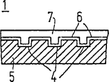
第1a図は、ディスク形状の情報担体1を示す。この情報担体は、記録を意図された連続トラック9を有し、このトラック9は、巻線のらせんパターンで配置されている。この巻線は、らせん状の代わりに同心状に配置されてもよい。このトラック9は、走査中において、例えばプレグルーブ部4が読み取り/書き込みヘッドに前記トラック9をたどることを可能とさせるような、サーボパターンによって情報担体上に示される。サーボパターンは、例えば、サーボトラッキングシステム内に信号を周期的に生じさせる、交番かつ均等に分布させられたサブパターンであってもよい。第1b図は、情報担体1のb−b線に沿った断面を示す。基板5は、ピックアップ層6及び透明層7で覆われている。プレグルーブ部4は、隆起部又は周囲と異なる材料特性として形成されてもよい。ピックアップ層6には、情報記録装置によって光学的に又は磁気光学的に書込みを行うことができる。情報担体上の情報は、マークのパターンで表される。トラック9内におけるパターン形成のため、例えば、各マークが、例えばそのマークの長さに依存する一定の又は変化する書き込みパワーの一つ又はそれ以上の記録パルスによって形成されるような、記録プロセスが使用される。例えば、書き込みパワー、パルス数、変量、デューティサイクル等のような記録プロセスの記録パラメタは、前記情報担体に最適に同調される。その際、この情報担体の材料特性は、重要な役割を果たす。書き込み可能な記録担体の一例は、コンピュータ用の既知のCD Write Once又はCD-MOである。担体情報を同じように有する書き込み可能なCDシステムの広域な記述は、米国特許公報第US-4,901,300号(PHN 12.398)及び米国特許公報第US-5,187,699号(PHQ88.002)に見られる。CDの読み取り及びプレグルーブ部の使用の詳細は、Bouwhuis等著の題名"Principles of optical disc systems" ISBN 0-8527-785-3に見られる。
【0009】
第1c図及び1d図は、前記プレグルーブ部の周期的変調(ウォッブル)の実施例を2つ示す。このウォッブルは、サーボトラッキングピックアップ内に付加的な信号を生じさせる。例えば前記ウォッブルは、補助信号で周波数変調され、担体情報は前記補助信号にコード化される。このような記録情報を有する情報担体の詳細は、上記で述べたヨーロッパ特許公報第EP-0 937 238号に見られる。光学テープのような異なる形式の情報担体は、例えばテープの最初で又は補助トラックに沿って情報領域を認識することによって、異なる方法で記録情報を与えられ得る。
【0010】
本発明に係る情報担体上の記録情報は、速度関連情報を含む。マークの形状は、使用される記録速度とはほぼ無関係であるべきである。例えば、増加される記録速度と一定のままの記録パラメタとで、異なる寸法のマークが形成されるであろう。熱効果が記録プロセスにおいて重要な役割を果たすので、全体として速度差に比例する記録パラメタの適合化は、同じ寸法のマークを得るには不十分である。同じ寸法を得るために、記録プロセスは記録速度に対してさらに適合化されなければならない。前記記録プロセスが、閉じた許容範囲内で実行されるべきであるCD erasable(CD-E)のような再記録可能且つ消去可能な情報担体で用いられる相変化材料に対して、これは特に当てはまる。本発明に係る情報担体に対し、速度関連情報は、記録プロセスと記録速度との間の関係を表す。結果として、実際の記録速度及び速度関連情報に依存して、記録速度が適合化されてもよいし、記録プロセスが適合化されてもよい。
【0011】
第2図は、この情報が、本発明に係る情報担体の1つの実施例におけるプレグルーブ部中の補助信号の連続ビットとして記録される際の、担体情報の1つの適切なフォーマットを示す。24ビット長ユニットが使用され、3個のバイトに再分割される。前記担体情報は、例えばアドレスコードAC及び補助コードHCを含み、このアドレスコードACは、CDシステムでは通例となっているように、トラックの始端に対するトラック9の読み取り部分の位置を、ビット位置13の分mm、ビット位置14の秒ss及びビット位置15のフレームffで示している。プレグルーブでの絶対時間の表示「Absolute Time Indication In The Pregroove(ATIP)」は、バイナリコード化された十進法「Binary Coded Decimal(BCD)」システムで表される。補助コードHCは、時間コードの最重要ビット(MSB)を形成する指定ビット位置20、21及び22での特定の値によって、アドレスコードACから区別される。これら3つのMSBにおいて、前記アドレスコードAC66及び67は、100、000をそれぞれ含み、補助コードHC61、62、63、64、65及び66は、残りの値010、110、001、011、111及び101を持つ。たとえば、与えられた位置で前記情報担体に設けられ記録装置によって読み取ることができるバーコード形式といった異なる形式で、前記記録担体上に前記速度関連情報が設けられてもよいことは、言うまでもない。
【0012】
第3図は、担体情報がコード化されるトラック9の一部を概略的に示す。補助信号は、本質的に、アドレスコードAC、及び10個の可能なコードの一つに補助コードHCを含む。前記補助コードHCは、例えばリードイン及びリードアウト領域の可能な始端及び終端のような前記情報担体1に関する記録情報、又は放射線ビームの必要な書き込みパワーのような記録プロセスの記録パラメタを有する。本発明の1つの実施例では、特定の補助コードHCにおけるいくつかのビットが、基準速度を表すのに使用される一方、他の記録パラメタは固定される。結果として、例えば通例の標準的な速度から離れる二倍の速度のような速度で、情報担体を最適化することが可能である。この速度で、前記情報担体の製造者は、残りの記録パラメタを測定し、それらを前記担体上に記録する。第2の実施例は、前記記録パラメタが使用でき、かつ前記情報担体が適する記録速度の範囲を持つ。前記速度の範囲は、最小速度及び最大速度の両方により示されてもよいが、最小速度又は最大速度が与えられるだけでも可能である。実際の記録速度は、この範囲内に入るべきである。公称記録速度から離れる場合、必要とされる限り、補正を記録パラメタへ施してもよい。記録パラメタが第1記録速度に対して与えられる第3の実施例において、前記第1記録速度から離れた少なくとも他の記録速度で計算された他の記録パラメタが与えられる。記録動作中においては、その記録速度に対するパラメタがディスク上で入手可能な、前記記録速度の一つが使用され得る。前記記録パラメタが第1記録速度で与えられる第4の実施例では、第2記録速度における前記記録パラメタからの偏差を示す補正パラメタが含まれている。結果として、記録パラメタに対する補正が、第1記録速度と使用される記録速度との間の差に依存して計算され得る。前記記録プロセスが第1記録速度で決められている第5の実施例では、プロセス情報が含まれる。このプロセス情報は、第1記録速度から離れたある記録速度で、異なる記録プロセスが使用されるべきであることを表す。この点において、例えば予熱パルス又は全く異なる一続きのパルスが、ある離れた記録速度で適用されることが示されてもよい。
【0013】
当然、情報担体上の速度関連情報の前記実施例の組み合わせは可能である。たとえば異なる基準速度と共に、情報担体上のこのような補助コードを数回提供することによって、異なる記録パラメタ及びもしかすると異なる記録プロセスが、異なる基準速度又はたとえば前記記録放射線源の異なる波長に対して示され得る。
【0014】
第4図は、速度関連情報を持つ記録情報の1つの実施例を示す。これは、第2図を参照して説明された補助コードのフォーマットを有し、MSB位置20、21、22におけるコード101は、それぞれの補助コードHCの残りのビットが、一致したフォーマットによる速度関連情報を含むことを示す。これは、例えば以下のように満たされる。W1−W3は、基準速度で気温25℃で785nmの波長を有する書き込みパワー数(mW)を示し、ここで000は5mWを示し、001は6mW等を示す。V1−V3は、基準速度であり、000は指定なし、001は1倍の公称CD速度、010は2倍の公称CD速度、011は4倍速の公称CD速度等を示す、U1−U7は、ディスクの目的を示す。0000000は一般的な使用等を示す。D1はディスクの形式を示し、0はCD-WO、1はCD-Erasableを示す。前記ビットS1−S3及びA1−A3は、サブ形式を示すのに使用され、各サブ形式に対して、必要に応じて異なる記録プロセスが生成されてもよい。ディスクの形式及びサブ形式は、残りのパラメタが転送される際のフォーマットを適合化するように使用されてもよい。例えばCD-WOは、CD-Eとは異なる記録パラメタを持つ異なる記録プロセスを必要とする。補助コードにおける様々なビットの意味は、示されるディスクの形式/サブ形式に依存したものとされ得る。CD-Eの中でさえ、異なる記録プロセスが必要とされる、異なる物理的実施例及び材料の選択が使用され得る。それぞれのプロセスも前記記録速度に依存するものであってもよい。
【0015】
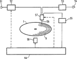
第5図は、ディスク形状の情報担体1に記録を行うための装置を示す。この装置は、記録プロセスに従っで情報担体1に記録を行うためのコード化手段52及び読み取り/書き込みユニット57を有する。情報は入力51に入力され、コード化手段52で記録信号に変換される。この記録信号は、読み取り/書き込みユニット57につながっている。前記情報担体1は、駆動手段58によって駆動され、回転する。前記読み取り/書き込みユニット57はその間、ビーム56を介してトラック9を走査し、前記トラック内に情報を表すマークのパターンを記録する。走査中、前記読み取り/書き込みユニット57は、従来形式のサーボシステム(図示せず)によってトラック9上に位置させられる。システムコントローラ59は、駆動手段58及びサーボシステムを介した、情報担体1の走査を検査する。システムコントローラ59は、コード化手段52及び読み込み/書き込みユニット57を介した、記録プロセスを同様に制御する。一般的に、このような装置は、前記読み込み/書き込みユニット57により読み出されたパターンから情報を回復するためのデコード手段53も有する。前記回復された情報は、次に出力54上に生成される。前記装置は、記録された情報を回復するための復調手段55をさらに含む。前記トラックを辿りながら生成されるサーボ信号は、補助信号の回復のためにサーボ信号を復調するように構成された復調手段55に出力される。復調手段55は、アドレスコードと補助信号からの補助コードとを変換する。これらのコードは、システムコントローラ59に転送される。前記記録プロセスの記録パラメタは、回復された記録された情報(なかでも速度関連情報)と記録速度との関数として、適合化手順(第6図参照)に従って、システムコントローラ59によって適合化される。例えば、使用される書き込みパワーは、読み取り/書き込みユニット57で設定され、記録される信号の形状は、コード化手段52で設定されてもよい。
【0016】
第6図は、以下のステップでシステムコントローラ59によって実行される適合化手順を概略的に示す。S1は、走査動作の開始であり、情報担体が前記装置に挿入された後、前記情報担体1は回転を始め、サーボシステムがロックオンする。S2は、記録された情報の読取りであり、前記トラックの所与の部分が走査される。復調器55は、記録された情報(なかでも速度関連情報)を読み取る。S3は、記録プロセスの適合化であり、前記記録パラメタは、記録指令に対して所望される記録速度と、前記情報担体から読み取られた記録された情報とから計算される。S4は、記録プロセスの校正であり、必要ならば一つ又はそれ以上の試験的記録が、記録パラメタの異なる設定で、情報担体上の試験的記録目的の領域で行われる。S5は、記録プロセスであり、記録命令が実行される。後続する命令は、次に情報担体が前記装置から取り除かれるまで実行されてもよい。この場合、適合化手順はS1から再開される。
【0017】
前記速度関連情報が、記録パラメタが与えられる基準速度を有する場合、S3は以下のように実行される。前記基準速度と実際の速度との間の差が与えられる。これらの速度が同じである場合、前記読み取られた記録パラメタは、直ちに適切ということになり、S4へと続く。差がある場合には、前記記録パラメタは、情報担体のそれぞれの形式に対するこの補正値が既知であるならば、固定値によって補正され得る。記録速度を適合化することもまた可能である。
【0018】
記録パラメタが第1記録速度で与えられ、速度関連情報が前記第1記録速度から離れた少なくとも1つの他の記録速度で与えられる他の記録パラメタを持つ場合、S3は以下のように実行される。前記与えられた速度の一つ、つまり、所望の記録速度からの差が最も少ない1つの速度が選択される。付帯の記録パラメタ及び実際の記録速度が設定され、S4へと続く。
【0019】
前記速度関連情報が、記録パラメタが使用できる記録速度範囲を有する場合、S3は以下のように実行される。所望の記録速度が前記範囲内である場合、S4が直ちに後続する。範囲外なら、実際の速度は、前記範囲内に置かれるように選択されるべきである。多くの場合において、可能な最大の速度が望まれ、この方法において簡単に得られる。前記情報担体が、異なる付帯の記録パラメタを持つ異なる速度範囲が使用できる形式であるならば、前記速度関連情報は当然ながら、全ての使用可能な速度の限界が見つかるような期間に亘って読まれ、この結果、選択は、所望の記録速度が置かれる範囲で行われ得る。
【0020】
記録パラメタが第1記録速度で与えられ、速度関連情報が第2記録速度における前記記録パラメタからの偏差を表す補正パラメタを含む場合、S3が以下のように実行される。前記第1記録速度と使用されるべき記録速度との間の差が特定される。前記補正パラメタは、この時、第2記録速度と実際の記録速度との間の速度差に比例して、記録パラメタへと適用される。例えば補正パラメタが、4倍の速度に対して与えられ、前記装置が2倍の速度のみ処理できるならば、当該補正は、半分にされるべきである。
【0021】
記録プロセスが第1記録速度で決められ、速度関連情報が、第1記録速度から離れた記録速度における少なくとも1つの他の記録プロセスを表すプロセス情報を有する場合、S3が以下のように実行される。所望の記録速度が、異なる記録プロセスが与えられた離れた速度と一致する場合、対応の記録プロセスが選択される。必要ならば、第2の実施例において、上記に記載した方法の一つにより、選択されたプロセスの記録パラメタの補正がさらにあってもよい。
【図面の簡単な説明】
【0022】
【図1】書き込み可能な形式の情報担体を示した図
【図2】情報担体に対する1つの適切なフォーマットを示した図
【図3】担体情報がコード化されるトラックの一部の概略的な図解
【図4】速度関連情報を持つ記録情報を示した図
【図5】情報担体に記録を行うための装置を示した図
【図6】適合化手順の概略的な説明図【Technical field】
[0001]
The present invention relates to a writable format information carrier that includes recording information indicating the recording process capable of recording information on the information carrier by a recording process, wherein the recording information includes a recording parameter of the recording process About.
[0002]
The invention further comprises an apparatus for recording on a writable information carrier, the information carrier comprising record information indicating the recording process capable of recording information on the information carrier by a recording process, The present invention relates to an apparatus in which recording information includes recording parameters of the recording process, and the apparatus includes reading means for reading the recording information and recording means for recording on an information carrier according to an actual recording process.
[Background]
[0003]
Such an information carrier and device are disclosed in EP-A-0 397 238 (PHN 12.925). This information carrier is an optically writable and readable disc such as Compact Disc Write Once (CD-WO) suitable for a CD system, for example, and has a prerecorded track portion, a so-called pregroove. This pregroove is intended to record an optically readable pattern according to a recording process. These patterns represent information. The pregroove is further modulated with an auxiliary signal including an address code and an auxiliary code. The auxiliary code has data necessary for recording, such as write power required for the recording process. The known device has means for recovering the auxiliary code and means for adapting the write power in response to the recovered auxiliary code. During this recording process, the information carrier is rotated at such a speed that the track moves at one recording speed fixed relative to one recording position. The recording may be done at a nominal recording speed equal to the conventional reading speed in the system, for example the nominal CD audio reading speed in a CD system. One problem with known information carriers and devices is that if the information carrier is recorded at a speed away from the nominal recording speed, the recorded pattern will deviate from the pattern recorded at the nominal recording speed. .
[0004]
Furthermore, US Pat. No. 5,457,674 discloses that an optical disc has prerecorded recording parameters in a certain area of the disc. This recording parameter includes the rotational frequency and the writing power for each rotational frequency. Furthermore, an apparatus for recording at a rotational frequency other than the frequency specified by the pre-recorded recording parameters on the disc is disclosed.
DISCLOSURE OF THE INVENTION
[Problems to be solved by the invention]
[0005]
One object of the present invention is to provide an apparatus and an information carrier that avoids a deviation pattern in which the information carrier is recorded at a speed away from a suitable recording speed.
[Means for Solving the Problems]
[0006]
For this purpose, the information carrier according to the present invention provides that the recording information includes speed-related information indicating the recording speed dependence of the recording process, the recording process being related to the recording speed, the speed-related information being It is characterized in that the recording parameters can be used and the information carrier includes a range of suitable recording speeds. For this purpose, the apparatus according to the present invention includes speed-related information in which the recording information indicates the recording speed dependency of the recording process, and the speed-related information can be used by the recording parameter. The carrier includes a suitable recording speed range, and the recording means controls the actual recording process depending on the actual recording speed and speed related information, and selects the actual recording speed depending on the recording speed range. It is comprised so that it may do. These measures have the advantage that, for example, the pattern has a substantially constant dimension regardless of the recording speed, since the recording process is easily adapted to the actual recording speed in the device. A further advantage is that the manufacturer of the information carrier may perform an adaptation of the recording process to the actual recording speed for each information carrier. This is particularly advantageous if a new information carrier or faster device is developed that can be recorded faster after a standardization agreement has been made. These measures are also advantageous, for example, in that it is possible to read directly from the information carrier whether the recording speed used is within the speed range of the information carrier where other recording parameters can be used.
BEST MODE FOR CARRYING OUT THE INVENTION
[0007]
These and other features of the present invention will be described with reference to FIGS. In these drawings, elements corresponding to the elements described above have similar symbols.
[0008]
FIG. 1a shows a disc-
[0009]
FIGS. 1c and 1d show two examples of periodic modulation (wobble) of the pregroove portion. This wobble causes an additional signal in the servo tracking pickup. For example, the wobble is frequency modulated with an auxiliary signal, and carrier information is encoded into the auxiliary signal. Details of such an information carrier having recorded information can be found in the above-mentioned European Patent Publication No. EP-0 937 238. Different types of information carriers, such as optical tapes, can be provided with recorded information in different ways, for example by recognizing information areas at the beginning of the tape or along auxiliary tracks.
[0010]
The recorded information on the information carrier according to the present invention includes speed related information. The shape of the mark should be largely independent of the recording speed used. For example, different sized marks will be formed with increased recording speed and constant recording parameters. Since the thermal effect plays an important role in the recording process, the adaptation of the recording parameters that are proportional to the speed difference as a whole is insufficient to obtain marks of the same size. In order to obtain the same dimensions, the recording process must be further adapted to the recording speed. This is especially true for phase change materials used on re-recordable and erasable information carriers such as CD erasable (CD-E) where the recording process should be performed within closed tolerances. . For the information carrier according to the invention, the speed related information represents the relationship between the recording process and the recording speed. As a result, depending on the actual recording speed and speed related information, the recording speed may be adapted or the recording process may be adapted.
[0011]
FIG. 2 shows one suitable format of carrier information when this information is recorded as successive bits of the auxiliary signal in the pregroove part in one embodiment of the information carrier according to the invention. A 24-bit long unit is used and subdivided into 3 bytes. The carrier information includes, for example, an address code AC and an auxiliary code HC, and this address code AC indicates the position of the read portion of the
[0012]
FIG. 3 schematically shows a part of the
[0013]
Of course, a combination of the above embodiments of speed related information on the information carrier is possible. By providing such an auxiliary code on the information carrier several times, for example with different reference velocities, different recording parameters and possibly different recording processes are shown for different reference velocities or different wavelengths of the recording radiation source, for example. Can be done.
[0014]
FIG. 4 shows one embodiment of recorded information having speed related information. This has the auxiliary code format described with reference to FIG. 2, and the code 101 at the MSB positions 20, 21, 22 is speed related with the format in which the remaining bits of each auxiliary code HC match. Indicates that information is included. This is satisfied, for example, as follows. W1-W3 indicates the number of write powers (mW) having a wavelength of 785 nm at a temperature of 25 ° C. at a reference speed, where 000 indicates 5 mW, 001 indicates 6 mW, and the like. V1-V3 is a reference speed, 000 is not specified, 001 is 1 × nominal CD speed, 010 is 2 × nominal CD speed, 011 is 4 × nominal CD speed, etc. U1-U7 is Indicates the purpose of the disc. 0000000 indicates general use. D1 indicates the disc format, 0 indicates CD-WO, and 1 indicates CD-Erasable. The bits S1-S3 and A1-A3 are used to indicate sub-types, and different recording processes may be generated for each sub-type as needed. The disc type and sub-type may be used to adapt the format in which the remaining parameters are transferred. For example, CD-WO requires a different recording process with different recording parameters than CD-E. The meaning of the various bits in the auxiliary code may be dependent on the disc type / subtype indicated. Even within CD-E, different physical embodiments and material choices may be used where different recording processes are required. Each process may also depend on the recording speed.
[0015]
FIG. 5 shows an apparatus for recording on a disc-shaped
[0016]
FIG. 6 schematically shows the adaptation procedure performed by the
[0017]
When the speed related information has a reference speed to which a recording parameter is given, S3 is executed as follows. The difference between the reference speed and the actual speed is given. If these velocities are the same, the read recording parameters will be immediately appropriate and continue to S4. If there is a difference, the recording parameter can be corrected by a fixed value if this correction value for each type of information carrier is known. It is also possible to adapt the recording speed.
[0018]
If the recording parameter is given at the first recording speed and the speed related information has other recording parameters given at at least one other recording speed away from the first recording speed, S3 is executed as follows: . One of the given speeds, that is, one speed with the smallest difference from the desired recording speed is selected. Ancillary recording parameters and actual recording speed are set and continue to S4.
[0019]
When the speed related information has a recording speed range in which the recording parameter can be used, S3 is executed as follows. If the desired recording speed is within the range, S4 immediately follows. If out of range, the actual speed should be selected to be within the range. In many cases, the maximum possible speed is desired and is easily obtained in this way. If the information carrier is in a format in which different speed ranges with different incidental recording parameters can be used, the speed related information will of course be read over a period in which all available speed limits are found. As a result, the selection can be made within a range where a desired recording speed is set.
[0020]
When the recording parameter is given at the first recording speed and the speed related information includes a correction parameter representing a deviation from the recording parameter at the second recording speed, S3 is executed as follows. A difference between the first recording speed and the recording speed to be used is identified. At this time, the correction parameter is applied to the recording parameter in proportion to the speed difference between the second recording speed and the actual recording speed. For example, if a correction parameter is given for a quadruple speed and the device can only handle a double speed, the correction should be halved.
[0021]
If the recording process is determined by the first recording speed and the speed-related information has process information representing at least one other recording process at a recording speed away from the first recording speed, S3 is executed as follows: . If the desired recording speed matches a remote speed given a different recording process, the corresponding recording process is selected. If necessary, in the second embodiment, there may be further correction of the recording parameters of the selected process by one of the methods described above.
[Brief description of the drawings]
[0022]
FIG. 1 is a diagram showing an information carrier in a writable form. FIG. 2 is a diagram showing one suitable format for the information carrier. [Fig. 4] A diagram showing recording information having speed related information. [Fig. 5] A diagram showing an apparatus for recording on an information carrier. [Fig.
Claims (9)
Applications Claiming Priority (3)
| Application Number | Priority Date | Filing Date | Title |
|---|---|---|---|
| BE9500809 | 1995-09-29 | ||
| BE9500809A BE1009677A3 (en) | 1995-09-29 | 1995-09-29 | INFORMATION CARRIER AND DEVICE FOR DESCRIBING AN INFORMATION CARRIER. |
| PCT/IB1996/000980 WO1997013244A1 (en) | 1995-09-29 | 1996-09-24 | Information carrier and recording device for recording an information carrier |
Related Child Applications (1)
| Application Number | Title | Priority Date | Filing Date |
|---|---|---|---|
| JP2007206881A Division JP2007335077A (en) | 1995-09-29 | 2007-08-08 | Information carrier, and recording device for recording on the same |
Publications (2)
| Publication Number | Publication Date |
|---|---|
| JPH11513521A JPH11513521A (en) | 1999-11-16 |
| JP4063321B2 true JP4063321B2 (en) | 2008-03-19 |
Family
ID=3889207
Family Applications (2)
| Application Number | Title | Priority Date | Filing Date |
|---|---|---|---|
| JP51409797A Expired - Lifetime JP4063321B2 (en) | 1995-09-29 | 1996-09-24 | Information carrier and recording device for recording on information carrier |
| JP2007206881A Pending JP2007335077A (en) | 1995-09-29 | 2007-08-08 | Information carrier, and recording device for recording on the same |
Family Applications After (1)
| Application Number | Title | Priority Date | Filing Date |
|---|---|---|---|
| JP2007206881A Pending JP2007335077A (en) | 1995-09-29 | 2007-08-08 | Information carrier, and recording device for recording on the same |
Country Status (17)
| Country | Link |
|---|---|
| US (1) | US5835462A (en) |
| EP (1) | EP0852796B1 (en) |
| JP (2) | JP4063321B2 (en) |
| KR (1) | KR100470007B1 (en) |
| CN (2) | CN100517473C (en) |
| AT (1) | ATE184416T1 (en) |
| BE (1) | BE1009677A3 (en) |
| CA (1) | CA2206297C (en) |
| CZ (1) | CZ291074B6 (en) |
| DE (1) | DE69604189T2 (en) |
| ES (1) | ES2138831T3 (en) |
| GR (1) | GR3031923T3 (en) |
| HK (1) | HK1012520A1 (en) |
| ID (1) | ID16343A (en) |
| MY (1) | MY120906A (en) |
| TW (1) | TW397974B (en) |
| WO (1) | WO1997013244A1 (en) |
Families Citing this family (75)
| Publication number | Priority date | Publication date | Assignee | Title |
|---|---|---|---|---|
| JP3442243B2 (en) * | 1996-07-12 | 2003-09-02 | ティアック株式会社 | Data reproduction method and apparatus |
| JP3743178B2 (en) * | 1998-10-05 | 2006-02-08 | ヤマハ株式会社 | Recordable optical disc and optical disc recording apparatus |
| US6275458B1 (en) * | 1999-02-18 | 2001-08-14 | Terrence L. Wong | Method and apparatus for reading and writing a multi-level signal from an optical disc |
| US6580683B1 (en) | 1999-06-23 | 2003-06-17 | Dataplay, Inc. | Optical recording medium having a master data area and a writeable data area |
| JP4145036B2 (en) * | 2000-09-28 | 2008-09-03 | 株式会社リコー | Optical information recording medium |
| ATE422092T1 (en) * | 2000-12-11 | 2009-02-15 | Koninkl Philips Electronics Nv | OPTICAL TYPE RECORDING MEDIUM AND RECORDING AND/OR REPRODUCING DEVICE FOR USE WITH SUCH RECORDING MEDIUM |
| KR100869279B1 (en) * | 2000-12-11 | 2008-11-18 | 코닌클리케 필립스 일렉트로닉스 엔.브이. | Record carrier of the optical type and a device for recording and/or playback for use with such a record carrier |
| US6904007B2 (en) * | 2001-01-25 | 2005-06-07 | Dphi Acquisitions, Inc. | Digital servo system with loop gain calibration |
| US7782721B2 (en) * | 2001-01-25 | 2010-08-24 | Dphi Acquisitions, Inc. | Digital focus and tracking servo system with multi-zone calibration |
| US6781929B2 (en) | 2001-01-25 | 2004-08-24 | Dphi Acquisitions, Inc. | Digital tracking servo system with multi-track seek |
| US7095683B2 (en) * | 2001-01-25 | 2006-08-22 | Dphi Acquisitions, Inc. | Tracking and focus digital servo system with write abort |
| US6930963B2 (en) | 2001-01-25 | 2005-08-16 | Dphi Acquistions, Inc. | Tracking and focus servo system with head load |
| US6891781B2 (en) * | 2001-01-25 | 2005-05-10 | Dphi Acquisitions, Inc. | Digital servo system with second order compensator |
| US7020054B2 (en) * | 2001-01-25 | 2006-03-28 | Dphi Acquisitions, Inc. | Digital servo system with biased feed-forward |
| US6728182B2 (en) | 2001-01-25 | 2004-04-27 | Dphi Acquisitions, Inc. | Tracking and focus servo system with a media type boundary crossing detector |
| US6965547B2 (en) * | 2001-01-25 | 2005-11-15 | Dphi Acquisitions, Inc. | Tracking and focus servo system with error signal inverse non-linearity calibration |
| US6738320B2 (en) | 2001-01-25 | 2004-05-18 | Dphi Acquisitions, Inc. | System and method for moving optical pick up from current position to target position with smooth control |
| US6956797B2 (en) * | 2001-01-25 | 2005-10-18 | Dphi Acquisitions, Inc. | Digital servo system with error signal integrity testing |
| US6906985B2 (en) | 2001-01-25 | 2005-06-14 | Dphi Acquisitions, Inc. | Calibration of tracking error signal gain in a tracking servo system |
| US6958957B2 (en) * | 2001-01-25 | 2005-10-25 | Dphi Acquisitions, Inc. | Digital tracking and focus servo system with TES to FES crosstalk calibration |
| US7260031B2 (en) | 2001-01-25 | 2007-08-21 | Dphi Acquisitions, Inc. | Digital focus and tracking servo system with one-track jump |
| US7522480B2 (en) | 2001-01-25 | 2009-04-21 | Dphi Acquisitions, Inc. | Digital tracking servo system with multi-track seek with an acceleration clamp |
| US6882601B2 (en) | 2001-01-25 | 2005-04-19 | Dphi Acquisitions, Inc. | Digital servo system with feed-forward control loops |
| US6847597B2 (en) | 2001-01-25 | 2005-01-25 | Dphi Acquisitions, Inc. | Optical disk drive with a digital focus and tracking servo system |
| US6847596B2 (en) | 2001-01-25 | 2005-01-25 | Dphi Acquisitions, Inc. | Tracking servo system including a multi-track seek algorithm with a track zero crossing period integrity test |
| US6950380B2 (en) * | 2001-01-25 | 2005-09-27 | Dphi Acquisitions, Inc. | Detector input dark current offset calibration in an optical disk drive digital servo |
| US6909676B2 (en) | 2001-01-25 | 2005-06-21 | Dphi Acquisitions, Inc. | Digital tracking servo system with multi-track seek with track zero crossing detection |
| US7593300B2 (en) | 2001-01-25 | 2009-09-22 | Dphi Acquisitions, Inc. | Digital tracking servo system with off-format detection |
| US6937543B2 (en) | 2001-01-25 | 2005-08-30 | Dphi Acquisitions, Inc. | Digital focus servo system with a sliding notch filter |
| US6762980B2 (en) | 2001-01-25 | 2004-07-13 | Dphi Acquisitions, Inc. | Digital tracking servo system with a multi-track seeking and accelerated servo function for regaining a closed tracking loop |
| US6922380B2 (en) | 2001-01-25 | 2005-07-26 | Dphi Acquisitions, Inc. | Tracking and focus servo system with anti-skate algorithm |
| US7196979B2 (en) | 2001-01-25 | 2007-03-27 | Dphi Acquisitions, Inc. | Calibration storage methods for a digital focus and tracking servo system with calibration |
| US7672199B2 (en) | 2001-01-25 | 2010-03-02 | Dphi Acquisitions, Inc. | Close focus algorithm in a digital focus servo system |
| US6704261B2 (en) | 2001-01-25 | 2004-03-09 | Dphi Acquisitions, Inc. | Spin motor control in an optical drive |
| US6891789B2 (en) * | 2001-01-25 | 2005-05-10 | Dphi Acquisitions, Inc. | Tracking and focus servo system with automatic media type detector |
| US6882603B2 (en) * | 2001-01-25 | 2005-04-19 | Dphi Acquisitions, Inc. | Digital tracking servo system with tracking skate detection |
| US6885619B2 (en) | 2001-01-25 | 2005-04-26 | Dphi Acquisitions, Inc. | Detector input stray light offset calibration in an optical disk drive |
| US6813228B2 (en) | 2001-01-25 | 2004-11-02 | Dphi Acquisitions, Inc. | Tracking and focus servo system with direction sensor |
| US7023776B2 (en) * | 2001-01-25 | 2006-04-04 | Dphi Acquisitions, Inc. | Calibration initiation methods for a tracking and focus servo system |
| US7414940B2 (en) | 2001-01-25 | 2008-08-19 | Dphi Acquisitions, Inc. | Calibration of a focus error signal gain in a focus servo system |
| US6809995B2 (en) | 2001-01-25 | 2004-10-26 | Dphi Acquisitions, Inc. | Digital focus and tracking servo system |
| US6970410B2 (en) * | 2001-01-25 | 2005-11-29 | Dphi Acquisitions, Inc. | Focus detection in a digital focus servo system |
| US6898164B2 (en) * | 2001-01-25 | 2005-05-24 | Dphi Acquisitions, Inc. | Close tracking algorithm in a digital tracking servo system |
| US7492675B2 (en) * | 2001-01-25 | 2009-02-17 | Dphi Acquisitions, Inc. | Digital servo system with calibrated notch filters |
| US7680004B2 (en) * | 2001-01-25 | 2010-03-16 | Dphi Acquisitions, Inc. | Digital servo system with inverse non-linearity compensation |
| US6970403B2 (en) * | 2001-01-25 | 2005-11-29 | Dphi Acquisition, Inc. | Calibration of tracking error signal offset in a tracking servo system |
| US7092322B2 (en) * | 2001-01-25 | 2006-08-15 | Dphi Acquisitions, Inc. | Calibration of focus error signal offset in a focus servo system |
| US7023766B2 (en) | 2001-01-25 | 2006-04-04 | Dphi Acquisitions, Inc. | Flexible servicing of servo algorithms using a digital signal processor |
| US7016280B2 (en) * | 2001-01-25 | 2006-03-21 | Dphi Acquisitions, Inc. | Tracking and focus servo system with defect detection |
| US6813226B2 (en) | 2001-01-25 | 2004-11-02 | Dphi Acquisitions, Inc. | Calibration of a focus sum threshold in a focus servo system |
| JP2002245625A (en) * | 2001-02-19 | 2002-08-30 | Pioneer Electronic Corp | Recording medium, information recording device and method, information recording medium and recording program |
| KR100567515B1 (en) | 2001-04-27 | 2006-04-03 | 마쯔시다덴기산교 가부시키가이샤 | Recordable optical disc, optical disc recording apparatus, optical disc reproduction apparatus, and method for recording data onto recordable optical disc |
| JP2003045036A (en) | 2001-07-27 | 2003-02-14 | Toshiba Corp | Optical disk, optical disk recording playback device and optical disk recording playback method |
| JP2003203341A (en) | 2001-11-02 | 2003-07-18 | Victor Co Of Japan Ltd | Optical disk, optical disk recording and playing back device, and optical disk recording and playing back method |
| JP4409949B2 (en) * | 2001-12-21 | 2010-02-03 | コーニンクレッカ フィリップス エレクトロニクス エヌ ヴィ | Recording medium and scanning device |
| TWI257624B (en) * | 2002-02-01 | 2006-07-01 | Matsushita Electric Ind Co Ltd | Information medium and information recording/reproduction apparatus |
| MXPA04010521A (en) * | 2002-04-24 | 2004-12-13 | Samsung Electronics Co Ltd | Optical information storage medium and method of recording thereon. |
| KR20030092588A (en) * | 2002-05-30 | 2003-12-06 | 삼성전자주식회사 | Optical information storage medium and method of recording/reproducing in the same |
| JP2004046966A (en) * | 2002-07-11 | 2004-02-12 | Ricoh Co Ltd | Optical information recording medium, recording condition deciding method, optical information recording device and information processor |
| EP1573721A1 (en) * | 2002-12-13 | 2005-09-14 | Koninklijke Philips Electronics N.V. | Record carrier comprising multiple sets of recording parameters |
| KR100750109B1 (en) * | 2003-02-15 | 2007-08-21 | 삼성전자주식회사 | Information storage medium |
| CN1759444A (en) * | 2003-03-11 | 2006-04-12 | 皇家飞利浦电子股份有限公司 | Dual-speed optical record carrier recording apparatus |
| KR100953637B1 (en) * | 2003-07-07 | 2010-04-20 | 엘지전자 주식회사 | Optical disc and recording method of Disc Information of optical disc |
| CA2474995C (en) * | 2003-07-07 | 2011-11-22 | Lg Electronics Inc. | Recording medium, method of configuring control information thereof, recording and/or reproducing method using the same, and apparatus thereof |
| CN101093677B (en) | 2003-07-07 | 2012-09-19 | Lg电子株式会社 | Recording medium, method for recording control information on recording medium and apparatus thereof |
| KR100976472B1 (en) * | 2003-07-07 | 2010-08-18 | 엘지전자 주식회사 | Optical disc and recording method of Disc Information of optical disc |
| US7564760B2 (en) | 2003-07-09 | 2009-07-21 | Lg Electronics, Inc. | Recording medium, method of configuring disc control information thereof, recording and reproducing method using the same, and apparatus thereof |
| CA2533105A1 (en) * | 2003-07-21 | 2005-01-27 | Koninklijke Philips Electronics N.V. | Method and apparatus for determining the optimal write power, and optical recording medium for use by such method and apparatus |
| MXPA04007512A (en) | 2003-08-14 | 2005-04-25 | Lg Electronics Inc | Recording medium, method of configuring control information thereof, recording and/or reproducing method using the same, and apparatus thereof. |
| DE602004026224D1 (en) * | 2003-08-14 | 2010-05-06 | Lg Electronics Inc | Recording medium, configuration method for control information, recording and reproducing method and apparatus therefor |
| KR101024904B1 (en) | 2003-08-14 | 2011-03-31 | 엘지전자 주식회사 | Recording medium,recording method, recording apparatus and recording/reproducing system |
| MXPA06001715A (en) * | 2003-08-14 | 2006-05-19 | Lg Electronics Inc | Recording medium, method of configuring control information thereof, recording and reproducing method using the same, and apparatus thereof. |
| JP2005166111A (en) * | 2003-11-28 | 2005-06-23 | Pioneer Electronic Corp | Recording medium, apparatus, method and program for information recording, and information recording medium |
| EP1751749B1 (en) * | 2004-05-13 | 2014-12-17 | LG Electronics Inc. | Recording medium, read/write method thereof and read/write apparatus thereof |
| KR101041809B1 (en) * | 2004-07-27 | 2011-06-17 | 엘지전자 주식회사 | Optical disc and configuring disc control information and recording/reproducing method using the same and apparatus thereof |
Family Cites Families (16)
| Publication number | Priority date | Publication date | Assignee | Title |
|---|---|---|---|---|
| FR2546325B1 (en) * | 1983-05-20 | 1988-07-08 | Thomson Csf | OPTICAL POWER CALIBRATION METHOD AND DEVICE APPLIED TO AN OPTICAL DISC FOR DATA RECORDING |
| JP2609593B2 (en) * | 1986-10-24 | 1997-05-14 | 株式会社日立製作所 | Disk medium recording method and disk device |
| JPS63205819A (en) * | 1987-02-20 | 1988-08-25 | Pioneer Electronic Corp | Optical information recorder |
| NL8800151A (en) * | 1988-01-22 | 1989-08-16 | Philips Nv | METHOD AND APPARATUS FOR RECORDING AN INFORMATION SIGNAL |
| US5187699A (en) * | 1988-01-22 | 1993-02-16 | U.S. Philips Corporation | Method and apparatus for successively recording two EFM-modulated signals enabling detection of boundary condition for transitioning between signals |
| US5418764A (en) * | 1988-01-22 | 1995-05-23 | U.S. Philips Corporation | Recording device, a record carrier having preformatted address codes and auxiliary codes providing control data for use by the recording device, and an information recording system including both the recording device and the record carrier |
| EP0397238B1 (en) * | 1989-05-08 | 1995-11-22 | Koninklijke Philips Electronics N.V. | Information recording system, and recording device and record carrier for use in such an information recording system |
| NL8901491A (en) * | 1989-06-13 | 1991-01-02 | Philips Nv | Recording audio signals on compact disc - combining digitised signal input with data relevant to recording speed and other characteristics |
| JPH03201266A (en) * | 1989-12-27 | 1991-09-03 | Victor Co Of Japan Ltd | Draw type information recording medium and its recording device |
| NL9000150A (en) * | 1990-01-22 | 1991-08-16 | Philips Nv | METHOD AND APPARATUS FOR APPLYING A PATTERN OF AREAS WITH CHANGED OPTICAL PROPERTIES IN A RECORD CARRIER |
| NL9000327A (en) * | 1990-02-12 | 1991-09-02 | Philips Nv | INFORMATION RECORDING DEVICE. |
| JP2896925B2 (en) * | 1990-09-04 | 1999-05-31 | 三菱電機株式会社 | Optical disk recording device |
| JP3039099B2 (en) * | 1992-02-14 | 2000-05-08 | ソニー株式会社 | Optical disk recording apparatus and method |
| JP2605577B2 (en) * | 1993-03-19 | 1997-04-30 | ヤマハ株式会社 | Optical disk recording device |
| JPH0773470A (en) * | 1993-09-03 | 1995-03-17 | Pioneer Electron Corp | Draw type optical disk and its recorder |
| JPH0773471A (en) * | 1993-09-03 | 1995-03-17 | Pioneer Electron Corp | Information recorder for draw type optical disk |
-
1995
- 1995-09-29 BE BE9500809A patent/BE1009677A3/en not_active IP Right Cessation
-
1996
- 1996-09-24 CZ CZ19971610A patent/CZ291074B6/en not_active IP Right Cessation
- 1996-09-24 CN CNB031457533A patent/CN100517473C/en not_active Expired - Lifetime
- 1996-09-24 WO PCT/IB1996/000980 patent/WO1997013244A1/en active IP Right Grant
- 1996-09-24 CN CNB961915323A patent/CN1149543C/en not_active Expired - Lifetime
- 1996-09-24 AT AT96929488T patent/ATE184416T1/en active
- 1996-09-24 CA CA2206297A patent/CA2206297C/en not_active Expired - Lifetime
- 1996-09-24 EP EP96929488A patent/EP0852796B1/en not_active Expired - Lifetime
- 1996-09-24 KR KR1019970703582A patent/KR100470007B1/en not_active IP Right Cessation
- 1996-09-24 DE DE69604189T patent/DE69604189T2/en not_active Expired - Lifetime
- 1996-09-24 JP JP51409797A patent/JP4063321B2/en not_active Expired - Lifetime
- 1996-09-24 ES ES96929488T patent/ES2138831T3/en not_active Expired - Lifetime
- 1996-09-27 MY MYPI96004010A patent/MY120906A/en unknown
- 1996-09-30 ID IDP962786A patent/ID16343A/en unknown
- 1996-09-30 US US08/722,651 patent/US5835462A/en not_active Expired - Lifetime
- 1996-12-10 TW TW085115279A patent/TW397974B/en not_active IP Right Cessation
-
1998
- 1998-12-21 HK HK98114109A patent/HK1012520A1/en not_active IP Right Cessation
-
1999
- 1999-11-23 GR GR990403014T patent/GR3031923T3/en unknown
-
2007
- 2007-08-08 JP JP2007206881A patent/JP2007335077A/en active Pending
Also Published As
| Publication number | Publication date |
|---|---|
| ATE184416T1 (en) | 1999-09-15 |
| CZ161097A3 (en) | 1999-04-14 |
| MY120906A (en) | 2005-12-30 |
| HK1012520A1 (en) | 1999-08-06 |
| DE69604189D1 (en) | 1999-10-14 |
| CN1475991A (en) | 2004-02-18 |
| EP0852796A1 (en) | 1998-07-15 |
| CA2206297A1 (en) | 1997-04-10 |
| WO1997013244A1 (en) | 1997-04-10 |
| JPH11513521A (en) | 1999-11-16 |
| US5835462A (en) | 1998-11-10 |
| GR3031923T3 (en) | 2000-03-31 |
| CA2206297C (en) | 2011-08-09 |
| ID16343A (en) | 1997-09-25 |
| DE69604189T2 (en) | 2000-04-13 |
| KR100470007B1 (en) | 2005-04-06 |
| ES2138831T3 (en) | 2000-01-16 |
| CN1149543C (en) | 2004-05-12 |
| CN100517473C (en) | 2009-07-22 |
| CZ291074B6 (en) | 2002-12-11 |
| KR980700646A (en) | 1998-03-30 |
| EP0852796B1 (en) | 1999-09-08 |
| JP2007335077A (en) | 2007-12-27 |
| BE1009677A3 (en) | 1997-06-03 |
| MX9703953A (en) | 1997-09-30 |
| TW397974B (en) | 2000-07-11 |
| CN1182497A (en) | 1998-05-20 |
Similar Documents
| Publication | Publication Date | Title |
|---|---|---|
| JP4063321B2 (en) | Information carrier and recording device for recording on information carrier | |
| EP0382154B1 (en) | Optical disc recording system | |
| US6760287B2 (en) | Optical disk unit | |
| JPH033168A (en) | Information recording system and recording device and recording carrier used for said information recording system | |
| US7027372B2 (en) | Recording and reproducing apparatus | |
| JP2621502B2 (en) | Optical disk recording method | |
| AU776509B2 (en) | Data record medium, recording apparatus, reproducing apparatus, and reproducing method | |
| JPH08329469A (en) | Data recorder | |
| JP3835581B2 (en) | Optical disc apparatus and test writing method | |
| JP2003141821A (en) | Data recording medium, data recording device and method and data reproducing device and method | |
| JP2002163862A (en) | Information recording/reproducing apparatus | |
| JP2726470B2 (en) | Recording medium and optical reader | |
| JPH08115523A (en) | Optical disk and optical disk driving device | |
| JP2001243722A (en) | Disk recording medium and disk drive device | |
| JP2900657B2 (en) | Optical disk drive | |
| US20080175131A1 (en) | Image Reader | |
| JP4470347B2 (en) | Optical disc apparatus and optical disc recording method | |
| JP2673063B2 (en) | Optical disk recording and reproducing method | |
| JP2002216350A (en) | Recording device | |
| JPH11162112A (en) | Optical disk device and method for detecting end of data | |
| MXPA97003953A (en) | Carrier of information and registration device to register an information carrier | |
| JP2002056607A (en) | Recorder, reproducing device and recording medium | |
| JP2003141742A (en) | Data recording medium, mastering apparatus and method, data recorder and data recording method, data reproducing apparatus and method | |
| JPH07161132A (en) | Optical disc recording/reproducing apparatus | |
| JPH08180498A (en) | Reproducing device and recording/reproducing device for magneto-optical disk |
Legal Events
| Date | Code | Title | Description |
|---|---|---|---|
| A131 | Notification of reasons for refusal |
Free format text: JAPANESE INTERMEDIATE CODE: A131 Effective date: 20060905 |
|
| A601 | Written request for extension of time |
Free format text: JAPANESE INTERMEDIATE CODE: A601 Effective date: 20061122 |
|
| A602 | Written permission of extension of time |
Free format text: JAPANESE INTERMEDIATE CODE: A602 Effective date: 20070122 |
|
| A524 | Written submission of copy of amendment under article 19 pct |
Free format text: JAPANESE INTERMEDIATE CODE: A524 Effective date: 20070220 |
|
| A02 | Decision of refusal |
Free format text: JAPANESE INTERMEDIATE CODE: A02 Effective date: 20070410 |
|
| A521 | Request for written amendment filed |
Free format text: JAPANESE INTERMEDIATE CODE: A523 Effective date: 20070808 |
|
| A911 | Transfer to examiner for re-examination before appeal (zenchi) |
Free format text: JAPANESE INTERMEDIATE CODE: A911 Effective date: 20070906 |
|
| TRDD | Decision of grant or rejection written | ||
| A01 | Written decision to grant a patent or to grant a registration (utility model) |
Free format text: JAPANESE INTERMEDIATE CODE: A01 Effective date: 20071127 |
|
| A61 | First payment of annual fees (during grant procedure) |
Free format text: JAPANESE INTERMEDIATE CODE: A61 Effective date: 20071225 |
|
| R150 | Certificate of patent or registration of utility model |
Free format text: JAPANESE INTERMEDIATE CODE: R150 |
|
| FPAY | Renewal fee payment (event date is renewal date of database) |
Free format text: PAYMENT UNTIL: 20110111 Year of fee payment: 3 |
|
| FPAY | Renewal fee payment (event date is renewal date of database) |
Free format text: PAYMENT UNTIL: 20120111 Year of fee payment: 4 |
|
| FPAY | Renewal fee payment (event date is renewal date of database) |
Free format text: PAYMENT UNTIL: 20130111 Year of fee payment: 5 |
|
| FPAY | Renewal fee payment (event date is renewal date of database) |
Free format text: PAYMENT UNTIL: 20140111 Year of fee payment: 6 |
|
| R250 | Receipt of annual fees |
Free format text: JAPANESE INTERMEDIATE CODE: R250 |
|
| R250 | Receipt of annual fees |
Free format text: JAPANESE INTERMEDIATE CODE: R250 |
|
| R250 | Receipt of annual fees |
Free format text: JAPANESE INTERMEDIATE CODE: R250 |
|
| EXPY | Cancellation because of completion of term |