JP4060504B2 - Blood component collection device - Google Patents
Blood component collection device Download PDFInfo
- Publication number
- JP4060504B2 JP4060504B2 JP35835999A JP35835999A JP4060504B2 JP 4060504 B2 JP4060504 B2 JP 4060504B2 JP 35835999 A JP35835999 A JP 35835999A JP 35835999 A JP35835999 A JP 35835999A JP 4060504 B2 JP4060504 B2 JP 4060504B2
- Authority
- JP
- Japan
- Prior art keywords
- blood
- collection
- centrifuge
- plasma
- rotor
- Prior art date
- Legal status (The legal status is an assumption and is not a legal conclusion. Google has not performed a legal analysis and makes no representation as to the accuracy of the status listed.)
- Expired - Fee Related
Links
Images


Landscapes
- Investigating Or Analysing Biological Materials (AREA)
- Sampling And Sample Adjustment (AREA)
- External Artificial Organs (AREA)
Description
【0001】
【発明の属する技術分野】
本発明は、血液中から所定の血液成分を分離する血液成分採取装置に関する。
【0002】
【従来の技術】
採血を行う場合、現在では、血液の有効利用および供血者の負担軽減などの理由から、採血血液を遠心分離などにより各血液成分に分離し、輸血者に必要な成分だけを採取し、その他の成分は供血者に返還する成分採血が行われている。
このような成分採血において、血小板製剤を得る場合、供血者から採血した血液を血液成分採取回路に導入し、該血液成分採取回路に設置された遠心ボウルと呼ばれる遠心分離器により、血漿、白血球、血小板および赤血球の4成分に分離し、その内の血小板を容器に回収して血小板製剤とし、残りの血漿、白血球および赤血球は、供血者に返血することが行われる。
【0003】
血小板採取方法として、例えば、特表平8−509403号公報に開示されている方式がある。この特表平8−509403号公報には、液体を全血に既定流速で加えて希釈しながら遠心ボウルに送るという第1の方式、遠心ボウルに全血を送り込み、遠心分離して低密度成分、中密度成分および高密度成分に分離し、低密度成分を第一の容器に取り出した後、回路を切り替えてその低密度成分を第一流速(定速)で循環させて遠心ボウル内の中密度成分領域を広げ、第二流速(加速)で再循環している間に中密度成分を取り出すという第2の方式が開示されている。
【0004】
【発明が解決しようとする課題】
遠心回転数は供血者によらず一定であり、採血時の血液流量が少ない場合には脱血量の増加に関連して採血時間が長くなり、遠心ボウル内部での血球成分の濃縮が一段と進んだ(高濃縮)状態となり血小板採取が巧く機能しないことがあった。
そこで、本発明の目的は、血小板の採取効率が高く、高濃度の血小板含有液を得ることができる血液成分採取装置を提供することにある。
【0005】
【課題を解決するための手段】
上記目的を達成するものは、内部に貯血空間を有するローターと、前記貯血空間に連通する流入口および流出口とを有し、前記ローターの回転により前記流入口より導入された血液を前記貯血空間内で遠心分離する遠心分離器と、採血針もしくは採血器具接続部と前記遠心分離器の流入口とを接続するための第1のラインと、前記遠心分離器の前記流出口に接続される第2のラインと、前記第1のラインに接続された抗凝固剤注入のための第3のラインと、前記第1のラインの途中に接続された第1チューブおよび前記第2のラインと接続された第2チューブを有する血漿採取バッグと、前記第2のラインに接続された血小板採取バッグとからなる血液成分採取回路を備えた血液成分採取装置であって、該血液成分採取装置は、前記遠心分離器の前記ローターを回転させるための遠心分離器駆動装置と、ヘマトクリット値入力部もしくはヘマトクリット値測定機能および制御部を備え、前記制御部は、ローター回転数を演算するローター回転数演算機能と、供血者の採血時の血流速度算出機能とを備え、該血流速度算出機能により算出された血流速度が一定値より大きい場合は、前記ローター回転数演算機能は、入力もしくは測定されたヘマトクリット値を用いて、該ヘマトクリット値に適したローター回転数を演算し、該血流速度算出機能により算出された血流速度が一定値以下の場合は、前記ローター回転数演算機能は、入力もしくは測定されたヘマトクリット値を用いて演算される該ヘマトクリット値に適したローター回転数よりも所定値低い回転数を演算し、前記ローター回転数演算機能により演算されたローター回転数にてローターを回転させるように遠心分離器駆動装置を制御する機能を備えている血液成分採取装置である。
【0006】
また、前記血液成分採取装置は、前記第1のラインと前記第1チューブとの接続部より遠心分離器側に配置され、前記第1のラインのための第1の送液ポンプと、前記第3のラインのための第2の送液ポンプと、前記血液成分採取回路の流路の開閉を行うための複数の流路開閉手段と、前記遠心分離器駆動装置、前記第1の送液ポンプ、前記第2の送液ポンプおよび前記複数の流路開閉手段を制御するための制御部を備え、さらに、前記制御部は、抗凝固剤が添加された血液の採取、採取された血液の分離および分離された血漿を前記血漿採取バッグ内に採取する血漿採取ステップと、該血漿採取ステップにより採取された前記血漿採取バッグ内の血漿を前記遠心分離器に循環させる血漿循環ステップとからなる少なくとも1回の血漿採取・循環ステップと、該血漿採取・循環ステップの終了後に、前記第1の送液ポンプによる血漿循環速度を加速させて、前記遠心分離器内より血小板を流出させ血小板を前記血小板採取バッグに採取する血小板採取ステップを行わせ、該血小板採取ステップの終了後、前記遠心分離器内の血液を返血する返血ステップを行わせる血小板採取操作が行われるように、前記遠心分離器駆動装置、前記第1の送液ポンプ、前記第2の送液ポンプおよび前記複数の流路開閉手段を制御するものであることが好ましい。
【0007】
そして、前記制御部は、前記血漿採取・循環ステップの終了後であって、前記第1の送液ポンプによる血漿循環速度を加速させる前に、前記第1の送液ポンプ、第2の送液ポンプを作動させて抗凝固剤が添加された血液を採取し、前記遠心分離器駆動装置を作動させて、血液より前記血漿採取バッグ内に所定量の血漿を採取する血漿採取ステップを行わせるものであることが好ましい。また、前記制御部は、前記血漿採取・循環ステップが2回行われるように制御するものであり、初回の血漿採取・循環ステップでは、前記血漿採取バッグ内の血漿を前記遠心分離器に定速にて循環させる血漿採取・定速循環ステップが行われ、2回目の血漿採取・循環ステップでは、前記血漿採取バッグ内の血漿を前記遠心分離器に加速させながら循環させる血漿採取・加速循環ステップが行われるように制御するものであることが好ましい。さらに、前記血液成分採取回路は、前記第2のラインに接続されたバフィーコート採取バッグを備え、前記制御部は、前記血小板採取ステップ終了後であって、前記返血ステップ前に、前記遠心分離器内よりバフィーコートを流出させバフィーコートを前記バフィーコート採取バッグに採取するバフィーコート採取ステップを行うものであることが好ましい。
【0008】
また、前記制御部は、前記バフィーコート採取ステップの終了後さらに血小板採取操作が行われる場合には、採取されたバフィーコートを次の血漿採取・循環ステップ前に前記遠心分離器内に返還するバフィーコート返還ステップを行わせるように、前記第1の送液ポンプおよび前記複数の流路開閉手段を制御するものであることが好ましい。
そして、前記制御部は、最低ローター回転数記憶機能を備え、前記ローター回転数演算機能により演算されたローター回転数が前記最低ローター回転数より大きい場合には、演算されたローター回転数にてローターを回転させるように遠心分離器駆動装置を制御し、前記ローター回転数演算機能により演算されたローター回転数が前記最低ローター回転数より小さい場合には、最低ローター回転数にてローターを回転させるように遠心分離器駆動装置を制御する機能を備えていることが好ましい。
【0009】
そして、前記ヘマトクリット値測定機能は、前記第1のラインであり、かつ抗凝固剤注入のための第3のラインとの接続部より採血針側の位置に設けられたヘマトクリット値測定用センサであってもよい。また、前記ヘマトクリット値測定機能は、最初の血漿採取ステップ時に遠心分離器を用いたヘマトクリット値測定機能であってもよい。
【0010】
【発明の実施の形態】
本発明の血液成分採取装置を図面に示した実施例を用いて説明する。
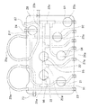
図1は、本発明の血液成分採取装置に使用される血液成分採取回路の構成例を示す平面図であり、図2は、図1の血液成分採取回路のカセットハウジング部分の平面図であり、図3は、血液成分採取回路に使用される遠心分離器に駆動装置が装着された状態の部分破断断面図であり、図4は、血液成分採取回路を装着した状態の本発明の血液成分採取装置の一実施例の概念図である。
本発明の血液成分採取装置1は、内部に貯血空間を有するローター142と、貯血空間に連通する流入口143および流出口144とを有し、ローター142の回転により流入口143より導入された血液を貯血空間内で遠心分離する遠心分離器20と、採血針29もしくは血液プールへの接続部と遠心分離器20の流入口143とを接続するための第1のライン21と、遠心分離器20の流出口144に接続された第2のライン22と、第1のライン21に接続され、抗凝固剤注入のための第3のライン23と、第1のライン21に接続された第1チューブ25aおよび第2のライン22と接続された第2チューブ25bを有する血漿採取バッグ25と、第2のライン22に接続された血小板採取バッグ26とを備える血液成分採取回路2のための血液成分採取装置である。
【0011】
血液成分採取装置1は、遠心分離器20のローター142を回転させるための遠心分離器駆動装置10と、第1のライン21のための第1の送液ポンプ11と、第3のライン23のための第2の送液ポンプ12と、血液成分採取回路2の流路の開閉を行うための複数の流路開閉手段81,82,83,84,85,86,87と、遠心分離器駆動装置10、第1の送液ポンプ11、第2の送液ポンプ12および複数の流路開閉手段を制御するための制御部13を備える。
この血液成分採取装置は、2つのポンプにより構成されているので、装置を小型化できる。
【0012】
そこで、最初に血液成分採取回路2について説明する。
この血液成分採取回路2は、血液成分、特に血小板を採取するための回路である。血小板採取回路2は、採血針29のような採血器具、もしくは採血針または血液プール接続部を有する採血器具への接続部(採血器具接続部)、採血針29もしくは採血器具接続部と遠心分離器20の流入口143とを接続し、第1のポンプチューブ21gを備える第1のライン21(採血および返血ライン)、遠心分離器20の流出口144と第1のライン21とを接続するための第2のライン22、第1のライン21の採血針29の近くに接続され、第2のポンプチューブ23aを備える第3のライン23(抗凝固剤注入ライン)、第1のライン21のポンプチューブ21gより採血針側に位置する分岐コネクター21fに接続された第1チューブ25aおよび第2のライン22と接続された第2チューブ25bを有する血漿採取バッグ25、第2のライン22に接続された第3チューブ26aを備える血小板採取バッグ26、第2のライン22に接続された第4チューブ27aを備えるバフィーコート採取バッグ27、第2のライン22に接続された液体(生理食塩水)注入用の第4のライン24を備える。血液成分採取回路2としては、採血針ではなく、血液バッグなどの血液プールに接続するための接続部(例えば、金属もしくは合成樹脂針)を備えるものでもよい。
【0013】
採血針29として、公知の金属針が使用される。第1のライン21は、採血針29が接続された採血針側第1ライン21aと遠心分離器20の流入口143とを接続された遠心分離器側第1ライン21bとからなる。採血針側第1ライン21aは、軟質樹脂製チューブが複数接続されて形成されている。採血針側第1ライン21aは、採血針側より、第3のライン23との接続用分岐コネクター21c、気泡およびマイクロアグリゲート除去のためのチャンバー21d、第2のライン22との接続用分岐コネクター21e、血漿採取バッグ25の第1チューブ25aとの接続用分岐コネクター21fを備える。チャンバー21dには、通気性かつ菌不透過性のフィルター21iが接続されている。遠心分離器側第1ライン21bは、第1チューブ25aとの接続用分岐コネクター21fに接続されており、その付近に形成されたポンプチューブ21gを有する。
【0014】
遠心分離器20の流出口144と第1のライン21とを接続する第2のライン22は、一端が遠心分離器20の流出口144に接続され、他端が第1のライン21の接続用分岐コネクター21eに接続されている。第2のライン22は、遠心分離器側から、血漿採取バッグ25の第2チューブ25bならびに血小板採取バッグ26の第3チューブ26aとの接続用分岐コネクター22a、第4のライン24との接続用分岐コネクター22b、気泡除去用フィルター22fを備えるチューブとの接続用分岐コネクター22c、バフィーコート採取バッグ27の第4チューブ27aとの接続用分岐コネクター22dを備える。
【0015】
第3のライン23は、一端が第1のライン21に設けられた接続用分岐コネクター21cに接続されている。第3のライン23は、コネクター21c側より、ポンプチューブ23a、異物除去用フィルター23b、気泡除去用チャンバー23c、抗凝固剤容器接続用針23dを備えている。
第4のライン24は、一端が第2のライン22の接続用分岐コネクター22bに接続されている。第4のライン24は、コネクター22b側より、異物除去用フィルター24a、生理食塩水容器接続用針24bを備えている。
血漿採取バッグ25は、第1のライン21のポンプチューブ21gより採血針側に位置する分岐コネクター21fに接続された第1チューブ25a、第2のライン22の分岐コネクター22aに接続された第2チューブ25bを有する。血小板採取バッグ26は、第2のライン22の分岐コネクター22aに接続された第3チューブ26aを備える。バフィーコート採取バッグ27は、第2のライン22の分岐コネクター22dに接続された第4チューブ27aを備える。
【0016】
上述した第1から第4のライン21,22,23,24の形成に使用されるチューブ、ポンプチューブ、さらに、バッグに接続されているチューブの構成材料としては、例えば、ポリ塩化ビニル、ポリエチレン、ポリプロピレン、PETやPBTのようなポリエステル、エチレン−酢酸ビニル共重合体、ポリウレタン、ポリエステルエラストマー、スチレン−ブタジエン−スチレン共重合体等の熱可塑性エラストマー等が挙げられるが、その中でも特に、ポリ塩化ビニルが好ましい。各チューブがポリ塩化ビニル製であれば、十分な可撓性、柔軟性が得られるので取り扱いがし易く、また、クレンメ等による閉塞にも適するからである。また、上述した分岐コネクターの構成材料についても、前記チューブの構成材料と同様のものを用いることができる。なお、ポンプチューブとしては、ローラーポンプにより押圧されても損傷を受けない程度の強度を備えるものが使用されている。
【0017】
血漿採取バッグ25、血小板採取バッグ26、バフィーコート採取バッグ27は、それぞれ、樹脂製の可撓性を有するシート材を重ね、その周縁部を融着(熱融着、高周波融着等)または接着して袋状にしたものが使用される。各バッグ25,26,27に使用される材料としては、例えば、軟質ポリ塩化ビニルが好適に使用される。この軟質ポリ塩化ビニルにおける可塑剤としては、例えば、ジ(エチルヘキシル)フタレート(DEHP)、ジ−(n−デシル)フタレート(DnDP)等が使用される。なお、このような可塑剤の含有量は、ポリ塩化ビニル100重量部に対し、30〜70重量部程度とするのが好ましい。
【0018】
また、上記各バッグ25,26,27のシート材料としては、ポリオレフィン、すなわちエチレン、プロピレン、ブタジエン、イソプレン等のオレフィンあるいはジオレフィンを重合または共重合した重合体を用いてもよい。具体的には、例えば、ポリエチレン、ポリプロピレン、エチレン−酢酸ビニル共重合体(EVA)、EVAと各種熱可塑性エラストマーとのポリマーブレンド等、あるいは、これらを任意に組み合わせたものが挙げられる。さらには、ポリエチレンテレフタレート(PET)、ポリブチレンテレフタレート(PBT)、ポリ−1,4−シクロヘキサンジメチルテレフタレート(PCHT)のようなポリエステル、ポリ塩化ビニリデンを用いることもできる。
なお、血小板採取バッグ26に使用されるシート材としては、血小板保存性を向上するためにガス透過性に優れるものを用いることがより好ましい。そのようなシート材としては、例えば、上述したポリオレフィンやDnDP可塑化ポリ塩化ビニル等を用いること、また、このような素材を用いることなく、上述したような材料のシート材を用い、厚さを比較的薄く(例えば、0.1〜0.5mm程度、特に、0.1〜0.3mm程度)したものが好適である。また、血小板採取バッグには、例えば、生理食塩水、GAC、PAS、PSM−1のような血小板保存液があらかじめ入れられていてもよい。
【0019】
そして、血液成分採取回路2の主要部分は、図2に示すように、カセット式となっている。血液成分採取回路2は、すべてのライン(第1のライン、第2のライン、第3のライン、第4のライン)およびすべてのチューブ(第1チューブ、第2チューブ、第3チューブ、第4チューブ)を部分的に収納しかつ部分的にそれらを保持し、言い換えれば、部分的にそれらが固定されたカセットハウジング28を備える。カセットハウジング28には、第1のポンプチューブ21gの両端および第2のポンプチューブ23aの両端が固定され、これらポンプチューブ21g,23aは、カセットハウジング28より、ローラーポンプの形状に対応したループ状に突出している。このため、第1および第2のポンプチューブ21g,23aは、ローラーポンプへの装着が容易である。
【0020】
さらに、カセットハウジング28は、カセットハウジング28内に位置する複数の開口部を備えている。具体的には、ポンプチューブ21gより採血針側部分の第1のライン21を露出させかつ、血液成分採取装置1の第1の流路開閉手段81の侵入が可能な第1の開口部91、血漿採取バッグ25の第1チューブ25aを露出させかつ血液成分採取装置1の第2の流路開閉手段82の侵入が可能な第2の開口部92、血漿採取バッグ25の第2チューブ25bを露出させかつ血液成分採取装置1の第3の流路開閉手段83の侵入が可能な第3の開口部93、血小板採取バッグ26の第3チューブ26aを露出させかつ血液成分採取装置1の第4の流路開閉手段84の侵入が可能な第4の開口部94、第2のライン22とバフィーコート採取バッグ27の第4チューブ27aとの接続部より遠心分離器側(上流側)の位置の第2のライン22を露出させかつ血液成分採取装置1の第5の流路開閉手段85の侵入が可能な第5の開口部95、第1のライン21との接続部とバフィーコート採取バッグ27の第4チューブ27aとの接続部との間(第2のライン22と第4チューブ27aとの接続部より下流側)の第2のライン22を露出させかつ血液成分採取装置1の第6の流路開閉手段86の侵入が可能な第6の開口部96、第4のライン24を露出させかつ血液成分採取装置1の第7の流路開閉手段87の侵入が可能な第7の開口部97を備えている。
【0021】
また、カセットハウジング28の内面には、上述した分岐コネクターが固定されている。さらに、カセットハウジング28の側面付近には、ハウジングの側面より突出するラインおよびチューブを保持し、かつハウジング部分での折れ曲がりを防止するための補強チューブが設けられている。カセットハウジング28は、内部に図2において破線で示す部分を収納可能な箱状体となっている。そして、カセットハウジング28は、ある程度の剛性を有する合成樹脂により形成されている。
血液成分採取装置1は、このカセットハウジング装着部(図示せず)を備えている。このため、カセットハウジング28を血液成分採取装置1のカセットハウジング装着部に装着することにより、カセットハウジング28の開口部より露出する部分の各ラインおよび各チューブが、自動的に対応する流路開閉手段に装着される。これにより回路の装着が容易であるとともに、血液成分採取準備も迅速に行える。また、血液成分採取装置1には、カセットハウジング装着部に近接して2つのポンプが設けられている。このため、カセットハウジング28より露出するポンプチューブのポンプへの装着も容易である。
【0022】
血液成分採取回路2に設けられている遠心分離器20は、通常遠心ボウルと呼ばれており、遠心力により血液成分を分離する。遠心分離器20は、図3に示すように、上端に流入口143が形成された鉛直方向に伸びる管体141と、管体141の周りで回転し、上部145に対し液密にシールされた中空のローター142とで構成されている。ローター142には、その底部および周壁内面に沿って流路(貯血空間)が形成され、この流路の上部に連通するように流出口144が形成されている。この場合、ローター142の容積は、例えば、100〜350ml程度とされる。
【0023】
ローター142は、血液成分採取装置1が備えるローター回転駆動装置10によりあらかじめ設定された所定の遠心条件(回転速度および回転時間)で回転される。この遠心条件により、ローター142内の血液の分離パターン(例えば、分離する血液成分数)を設定することができる。本実施例では、図3に示すように、血液がローター142の流路内で内層より血漿層131、バフィーコート層132および赤血球層133に分離されるように遠心条件が設定される。
【0024】
次に、図4に示す本発明の血液成分採取装置1について説明する。
血液成分採取装置1は、遠心分離器20のローター142を回転させるための遠心分離器駆動装置10と、第1のライン21のための第1の送液ポンプ11と、第3のライン23のための第2の送液ポンプ12と、血液成分採取回路2の流路の開閉を行うための複数の流路開閉手段81,82,83,84,85,86,87と、遠心分離器駆動装置10、第1の送液ポンプ11、第2の送液ポンプ12および複数の流路開閉手段を制御するための制御部13を備える。さらに、血液成分採取装置1は、第2チューブ25bとの接続部22aより遠心分離器側(上流側)の第2のライン22に装着される濁度センサ14、遠心分離器20の上方に取り付けられた光学式センサ15と、血漿採取バッグ25の重量を検知するための重量センサ16を備える。
【0025】
この実施例では、血液成分採取装置は、ヘマトクリット値入力部を備えている。制御部13は、第1の送液ポンプ11および第2の送液ポンプ12のための2つのポンプコントローラ(図示せず)を備え、制御部13の制御機構と第1の送液ポンプ11および第2の送液ポンプ12とはポンプコントローラを介して電気的に接続されており、さらに、遠心分離器駆動装置(ローター駆動装置)10が備える駆動コントローラとも電気的に接続されている。制御部13は、供血者の採血時の血流速度によって、遠心分離器のローターの遠心回転数を変更する機能を備えている。特に、この実施例の血液成分採取装置では、供血者の血液成分濃度(具体的には、ヘマトクリット値)および供血者の採血時の血流速度によって、遠心分離器のローターの遠心回転数を変更する機能を備えている。供血者の血液成分濃度としては、例えば、ヘマトクリット値、ヘマトクリット値と血小板濃度から算出される採取予想血小板数、血小板濃度、さらには、平均赤血球容積、性別、身長、体重であってもよい。
【0026】
また、制御部13は、最低ローター回転数記憶機能と、供血者の血液成分濃度を用いかつ供血者の採血時の血流速度を考慮してローター回転数を演算するローター回転数演算機能とを備え、ローター回転数演算機能により演算されたローター回転数が最低ローター回転数より大きい場合には、演算されたローター回転数にてローターを回転させるように遠心分離器駆動装置を制御し、演算されたローター回転数が最低ローター回転数より小さい場合には、最低ローター回転数にてローターを回転させるように遠心分離器駆動装置を制御する機能を備えている。
具体的には、血液成分採取装置は、遠心分離器の前記ローターを回転させるための遠心分離器駆動装置と、ヘマトクリット値入力部もしくはヘマトクリット値測定機能を備え、制御部は、ローター回転数を演算するローター回転数演算機能と、供血者の採血時の血流速度算出機能と、最低ローター回転数記憶機能とを備え、血流速度算出機能により算出された血流速度が一定値より大きい場合は、ローター回転数演算機能は、入力もしくは測定されたヘマトクリット値を用いて、ヘマトクリット値に適したローター回転数を演算し、血流速度算出機能により算出された血流速度が一定値以下の場合は、ローター回転数演算機能は、入力もしくは測定されたヘマトクリット値を用いて演算されるヘマトクリット値に適したローター回転数よりも所定値低い回転数を演算し、そして、ローター回転数演算機能により演算されたローター回転数が最低ローター回転数より大きい場合には、演算されたローター回転数にてローターを回転させるように遠心分離器駆動装置を制御し、演算されたローター回転数が最低ローター回転数より小さい場合には、最低ローター回転数にてローターを回転させるようにて遠心分離器駆動装置を制御する機能を備えている。
【0027】
より具体的には、制御部13は、ローター回転数演算機能として、ヘマトクリット値とローター回転数の適正関係式データ記憶部と、供血者の採血時の血流速度算出機能と、入力もしくは後述する測定されたヘマトクリット値と記憶されているヘマトクリット値とローター回転数の適正関係式データより、適正ローター回転数を演算する機能を備えている。ヘマトクリット値とローター回転数の適正関係式データは、多くのヘマトクリット値の血液を用いて各種のローター回転数により実際に血小板の採取を行い良好な結果が得られたデータ(ヘマトクリット値とローター回転数の組み合わせ)より算出することができる。関係式は、一次、二次さらには高次の回帰式として表すことができる。本発明者らが得たヘマトクリット値(x:%)とローター回転数(y:rpm)の適正関係式データの例は、以下の通りである。
【0028】
y=40x+3000
y=−0.94505x2+110.18x+1744
y=0.0667x3−8.7619x2+391.9x−1277.4
【0029】
これら、いずれの適正関係式データの例においても、傾向としては、ヘマトクリット値が低ければ適正ローター回転数も低くなり、逆にヘマトクリット値が高ければ適正ローター回転数も高くなる。
そして、ヘマトクリット値(x)が入力されると、記憶されている上記のようなヘマトクリット値とローター回転数の適正関係式データより、適正ローター回転数(y)が演算される。そして、必要時(後述する血漿採取・循環ステップ時、第2の血漿採取・循環ステップ時)にローター回転数演算機能により演算されたローター回転数にてローターを回転させるように遠心分離器駆動装置を制御する。
【0030】
このようにヘマトクリット値に対応して、ローター回転数を変化させることにより、例えば、低ヘマトクリット値の供血者の場合では、パッキングと呼ばれる過剰遠心による分離血液成分層の過剰圧縮現象を起こすことを防止できる。このようなパッキングが生じると、血小板層も圧縮されるため血小板の採取が困難となり採取効率が悪くなる。また、逆に、高ヘマトクリット値の供血者の場合では、遠心不足による分離不十分な状態を起こすことを防止できる。このような分離不十分な状態が生じると、血小板層内に位置しない多くの血小板が、血球層もしくは血漿中に存在し、採取効率が悪くなる。しかし、本発明の装置では、上記のようなパッキング現象も分離不十分状態の発生も極めて少なくなり、効率のよい血小板採取を行うことができる。
【0031】
さらに、制御部13は、供血者の採血時の血流速度によって、遠心分離器のローターの遠心回転数を変更する機能を備えている。特に、この実施例の血液成分採取装置では、供血者の血液成分濃度(具体的には、ヘマトクリット値)および供血者の採血時の血流速度によって、遠心分離器のローターの遠心回転数を変更する機能を備えている。具体的には、上記のヘマトクリット値を用いて算出されるローター回転数を修正するものである。
【0032】
制御部13は、下記の式1を記憶している。
VDAVE=BPV÷(T1−T2)・・・(式1、血液流速算出式)
式1は、採血動作中の平均採血速度を算出するためのものであり、
T1:採血開始から血小板採取直前の加速工程開始までの時間
T2:循環動作を行い、採血が停止している時間の合計
BPV:そのサイクルにて処理(採血)した血液の総量
平均採血速度:VDAVE
【0033】
そして、血液流速算出機能により算出された平均採血速度:VDAVEが一定流量以下(具体的には、40ml/min以下)の低流量である場合には、下記式によりローター回転数を演算する。
N(修正ローター回転数)=y−D
かつ
N(修正ローター回転数)≧4400
Dは任意の固定値(所定値)であり、100〜800が好適であり、例えば、400である。つまり、平均採血速度:VDAVEが一定流量以下の場合には、4400rpm以上である限り一律に所定値(400rpm)を通常演算値より減じたものを調整ローター回転数として出力し、これによりローターを回転させる。
【0034】
なお、血流速度は、上記のような演算によるものではなく、血液成分採取回路(例えば、第1のライン21)に内部を流れる血液流速を測定するためのセンサ(例えば、電磁式流量計)を設け、実測してもよい。この場合には、第1回目の血漿採取ステップの途中より、実測された血流速度が所定値以下の場合には、ローターの回転数を再度演算し、演算された修正ローター回転数によりローターの回転を制御してもよい。
【0035】
また、上記では、血液流量が低流量である場合に、所定値(400rpm)を通常演算値より減ずるものとなっているが、所定値(固定値)ではなく、算出される血液流量により変化するものであってもよい。このような場合の演算式としては、
N=y−(1/VDAVE)×E
かつ
N(修正ローター回転数)≧4400
としてもよい。Eは任意の固定値であり、4000〜32000が好適であり、例えば16000である。
【0036】
また、制御部としては、上記のように一度y(ローター回転数)を演算し、それを用いて修正ローター回転数Nを算出するものに限定されるものではなく、血液流速算出機能により算出された平均採血速度:VDAVEが一定流量以下(具体的には、40ml/min以下)の低流量である場合に用いられる下記のような低流量時ローター回転数演算式のいずれか1つを記憶しているものであってもよい。
y=40x+3000−D かつ y≧4400
y=−0.94505x2+110.18x+1744−D かつ y≧4400
y=0.0667x3−8.7619x2+391.9x−1277.4−D
かつ y≧4400
【0037】
また、流路開閉手段81,82,83,84,85,86,87も、すべて制御部に接続され、それらの開閉は制御部13により制御されている。さらに、濁度センサ14、遠心分離器20の上方に取り付けられた光学式センサ15、血漿採取バッグ25の重量を検知するための重量センサ16も、制御部13と電気的に接続され、それらより出力される信号は制御部13に入力される。制御部13は、例えばマイクロコンピュータで構成される制御機構およびローター回転数演算機能を有し、上述した重量センサ16、光学式センサ15、濁度センサ14からの検出信号は、制御部13へ随時入力される。制御部13は、濁度センサ14、光学式センサ15、重量センサ16からの信号に基づき、各ポンプの回転、停止、回転方向(正転/逆転)を制御するとともに、必要に応じ、各流路開閉手段の開閉および遠心分離器回転駆動装置10の作動(ローターの回転)を制御する。
【0038】
第1の流路開閉手段81は、ポンプチューブ21gより採血針側において第1のライン21を開閉するために設けられている。第2の流路開閉手段82は、血漿採取バッグ25の第1チューブ25aを開閉するために設けられている。第3の流路開閉手段83は、血漿採取バッグ25の第2チューブ25bを開閉するために設けられている。第4の流路開閉手段84は、血小板採取バッグ26の第3チューブ26aを開閉するために設けられている。第5の流路開閉手段85は、第2のライン22とバフィーコート採取バッグ27の第4チューブ27aとの接続部22dより遠心分離器側(上流側)の位置にて、第2のライン22を開閉するために設けられている。第6の流路開閉手段86は、第1のライン21との接続部21eと第4チューブ27aとの接続部との間(第2のライン22と第4チューブ27aとの接続部より下流側)の位置にて、第2のライン22を開閉するために設けられている。第7の流路開閉手段87は、第4のライン24を開閉するために設けられている。流路開閉手段は、ラインもしくはチューブの挿入部を備え、挿入部には、例えば、ソレノイド、電動モータ、シリンダ(油圧または空気圧)等の駆動源で作動するクランプを有する。具体的には、空気圧で作動する空圧シリンダクランプが好適である。流路開閉手段のクランプは、制御部13からの信号に基づいて作動する。
【0039】
ローター駆動装置10は、図3に示すように、遠心分離器20を収納するローター回転駆動装置ハウジング151と、脚部152と、駆動源であるモータ153と、遠心分離器20を保持する円盤状の固定台155とで構成されている。ハウジング151は、脚部152の上部に載置、固定されている。また、ハウジング151の下面には、ボルト156によりスペーサー157を介してモータ153が固定されている。モータ153の回転軸154の先端部には、固定台155が回転軸154と同軸でかつ一体的に回転するように嵌入されており、固定台155の上部には、ローター142の底部が嵌合する凹部が形成されている。また、遠心分離器20の上部145は、図示しない固定部材によりハウジング151に固定されている。ローター回転駆動装置10では、モータ153を駆動すると、固定台155およびそれに固定されたローター142が、例えば、回転数3000〜6000rpmで回転する。
【0040】
また、ローター回転駆動装置ハウジング151の内壁には、遠心分離器内の分離された血液成分の界面(例えば、血漿層131とバフィーコート層132との界面B、バフィーコート層132と赤血球層133との界面)の位置を光学的に検出する光学式センサ15が、取付部材158により設置、固定されている。この光学式センサ15としては、遠心分離器20の外周面に沿って上下方向に走査し得る光学式センサが用いられる。このセンサは、遠心分離器20の肩の部分に向けて光を照射する光源と、遠心ボウルから反射して戻ってくる光を受光する受光部で構成されている。つまり、LEDまたはレーザーのような発光素子と受光素子とが列状に配置され、発光素子から発せられた光の血液成分での反射光を受光素子により受光し、その受光光量を光電変換するように構成されている。分離された血液成分(例えば、血漿層131とバフィーコート層132)により反射光の強度が異なるため、受光光量が変化した受光素子に対応する位置が、界面Bの位置として検出される。より具体的には、遠心分離器20の光が通過する位置が透明な液体(血漿や水)で充填されている時と、バフィーコート層で充填されている時の、受光部での受光量の差から、バフィーコート層が光通過部に到達したことが検知される。バフィーコート層を検出する位置は、光がボウル内を通過する位置を変えることで調節され、通常は、光線通過位置を決めたら、そこで固定する。
【0041】
濁度センサ14は、第2のライン22中を流れる流体の濁度を検知するためのものであり、濁度に応じた電圧値を出力する。具体的には、濁度が高い時には低電圧値、濁度が低い時には高電圧値を出力する。
第1のライン21のポンプチューブ21gが装着される第1の送液ポンプ11ならびに第3のライン23のポンプチューブ23aが装着される第2の送液ポンプ12としては、ローラーポンプ、ペリスタリックポンプなどの非血液接触型ポンプが好適である。また、第1の送液ポンプ11(血液ポンプ)としては、いずれの方向にも血液を送ることができるものが使用される。具体的には、正回転と逆回転が可能なローラーポンプが用いられている。
【0042】
制御部は、抗凝固剤が添加された血液の採取、採取された血液の分離および分離された血漿を血漿採取バッグ内に採取する血漿採取ステップと、この血漿採取ステップにより採取された血漿採取バッグ内の血漿を遠心分離器に循環させる血漿循環ステップとからなる少なくとも1回の血漿採取・循環ステップと、この血漿採取・循環ステップの終了後に、第1の送液ポンプによる血漿循環速度を加速させて、遠心分離器内より血小板を流出させ血小板を血小板採取バッグに採取する血小板採取ステップと、この血小板採取ステップの終了後、遠心分離器内の血液を返血する返血ステップを行わせるものである。
【0043】
具体的には、制御部13は、第1の送液ポンプ11、第2の送液ポンプ12を作動させて抗凝固剤が添加された血液を採取し、遠心分離器駆動装置10を作動させて(上述した演算値もしくは設定値にて、ローターを回転させて)、血液より血漿採取バッグ25内に第1の所定量の血漿を採取する第1の血漿採取ステップを行わせ、次に、採血を一時中断し、かつ、遠心分離器駆動装置10を作動させて(上述した演算値もしくは設定値にて、ローターを回転させて)、血漿採取バッグ内の血漿を遠心分離器20に定速にて循環させる定速血漿循環ステップ(定速サーキュレーション)からなる血漿採取・定速循環ステップを行わせ、次に、第1の送液ポンプ11、第2の送液ポンプ12を作動させて抗凝固剤が添加された血液を採取し、遠心分離器駆動装置10を作動させて(上述した演算値もしくは設定値にて、ローターを回転させて)、界面センサにより所定位置(例えば、バフィーコート層)を検出するまで血漿を採取する第2の血漿採取ステップと、この第2の血漿採取ステップ終了後に、採血を一時中断し、かつ、遠心分離器駆動装置10を作動させて(上述した演算値もしくは設定値にて、ローターを回転させて)、血漿採取バッグ25内の血漿を遠心分離器20に加速させながら循環させる加速血漿循環ステップ(加速サーキュレーション)とからなる血漿採取・加速循環ステップ、この血漿採取・循環ステップの終了後に、第1の送液ポンプ11による血漿循環速度を加速させて、遠心分離器20内より血小板を流出させ血小板を血小板採取バッグに採取する血小板採取ステップと、この血小板採取ステップの終了後、遠心分離器20内の血液を返血する返血ステップを行わせるものである。なお、第2の血漿採取ステップでは、界面センサで検出するため、血漿バッグの重量検知を行わない。
【0044】
このように、1回の血小板採取操作中に、採血を一時中止しそして採取された血漿を遠心分離器に再循環する血漿再循環ステップが少なくとも2回行われ、かつ、後半の血漿再循環ステップが加速循環となっているため、遠心分離器内での血球層、バフィーコート層(BC層)が過剰圧縮されることを抑制し、赤血球層に埋もれた血小板を舞上げ、BC層に取り込むことができる。また、BC層自体も舞い上がるため、BC層内の血小板と白血球との分離と整列を促進する。このため、白血球の混入が少なく、かつ血小板の採取効率も高い血小板含有液(濃厚血小板血漿)を得ることができる。
【0045】
さらに、この実施例の血液成分採取装置1の制御部13は、上述した血漿採取・定速循環ステップ、血漿採取・加速循環ステップ、血小板採取ステップ、返血ステップからなる血小板採取操作が2回行われるように、遠心分離器駆動装置10、第1の送液ポンプ11、第2の送液ポンプ12および複数の流路開閉手段を制御するものである。
【0046】
さらに、この実施例の血液成分採取装置1の制御部13は、血小板採取ステップ終了後であって、返血ステップ前に、第1の送液ポンプ11による血漿循環速度を血小板採取ステップにおける最終速度よりも高くし、遠心分離器20内よりバフィーコートを流出させバフィーコートをバフィーコート採取バッグ27に採取するバフィーコート採取ステップを行うように制御する。なお、バフィーコート採取ステップは、上記の方法に限定されるものではなく、例えば、第1の送液ポンプ11による血漿循環速度を血小板採取ステップにおける最終速度を維持し、かつ、遠心分離器20のローターの回転速度を下げることにより行ってもよい。さらに、バフィーコート採取ステップは、第1の送液ポンプによる血漿循環速度を血小板採取ステップにおける最終速度より高くするとともに、遠心分離器のローターの回転速度を下げることにより行ってもよい。
そして、バフィーコート採取ステップの終了後、採取されたバフィーコートを次の採血ステップの前に遠心分離器20内に返還するバフィーコート返還ステップを行わせるように、第1の送液ポンプ11および複数の流路開閉手段を制御する。
【0047】
血小板採取操作をより具体的に説明する。
最初に、オペレータが成分採血を開始する直前に供血者より採血したサンプリング血液を用いて、事前に血球成分測定を行う。この時測定された供血者のヘマトクリット値を装置に入力することによって制御部は最適ローター回転数(初期ローター回転数)を算出する。その後必要な他のパラメータを入力する。そして、第3のライン23と採血針29を抗凝固剤でプライミングし、その後ドナーに穿刺針を穿刺し、成分採血を始める。また、採血開始と同時に平均採血速度を計算するための採血時間計測タイマーをスタートさせる。
【0048】
全血に抗凝固剤を所定(全血に対して、1/8〜1/20、具体的には1/10)比率で加え、所定速度(250ml/min以下;好ましくは、150〜40ml/min以下、具体的には、60ml/min以下)で第1のライン21を介して遠心分離器20に送り、遠心分離器20を所定回転数[3000〜6000rpm、好ましくは、4400〜5800rpmの範囲であって供血者のヘマトクリット値を利用して自動計算された値(初期ローター回転数)]で回転させて血液を血漿、バフィーコート、赤血球の各成分に分離し、血漿が遠心分離器20をオーバーフローしたら血漿バッグに採取し、血漿を所定量(10〜150ml、好ましくは、20〜30ml)採取した時点で送血を停止して、血漿を所定条件(採血量よりも大きい速度であり、60〜250ml/minで10〜90sec、具体的には、第1循環が200ml/minx30sec)で、第1のライン21および第2のライン22を通して遠心分離器20に戻す、定速血漿循環を行う。
【0049】
そして、再び、全血に抗凝固剤を所定(全血に対して、1/8〜1/20、具体的には1/10)比率で加え、所定速度(250ml/min以下;好ましくは、150〜40ml/min以下、具体的には、60ml/min以下)で第1のライン21を介して遠心分離器20に送り、遠心分離器20を所定回転数(3000〜6000rpm、好ましくは、4700〜4800rpm)で回転させて血液を血漿、バフィーコート、赤血球の各成分に分離し、遠心分離器20内部の血球界面位置をバフィーコート界面検出センサにて検出した時点で送血を停止して、血漿を所定条件(初速60〜80ml/min、最終到達速度(設定速度)150〜250ml/min、加速条件(1秒間毎に)2〜10ml/minの速度上昇、循環時間10〜90sec)で、第1のライン21および第2のライン22を通して遠心分離器20に戻す、加速血漿循環を行う。
【0050】
この時までの採血時間および血液処理量より平均採血速度(血流速度)を計算し、所定の速度に到達しない場合には、上述したようにローター回転数を再演算する。このときに計算されたローター回転数はこの直後に行われる血小板採取およびバフィーコート採取の動作終了後より利用される。つまり、次のサイクルの採血工程よりローター回転数は変更される。
そして、所定条件(採血量;100〜2500/Hct%[ml]、具体的には、250〜1000/Hct%[ml])条件で再び抗凝固剤を添加しながら微量の全血を採血する。
【0051】
最後の採血が行われた後、血漿を所定条件で第1および第2のライン22を通して遠心分離器20に戻し、所定条件にて段階的に加速度を上昇させて(ステップワイズな加速;0.1〜99ml/min/sec,具体的には、2〜10ml/min/sec)血小板採取速度(60〜250ml/min;実際は200ml/min)に到達させ、遠心分離器20より、流出してきた血小板を血小板採取バッグ26に採取するものである。さらに、この装置では、血小板採取後、血液循環速度を維持(60〜250ml/min、具体的には、200ml/min)し、かつ、遠心分離器20の回転数を下げる(今までの回転数より、100〜300rpm程度下げる)ことにより、流出してきたバフィーコートを採取し、次のサイクルの採血を行う前に、採取したバフィーコートを遠心分離器20に供給するようになっている。なお、バフィーコートの採取は、血小板採取後、血液循環速度を所定速度(血小板採取速度以上、好ましくは、60〜250ml/min、具体的には、205ml/min)に加速することにより行ってもよい。
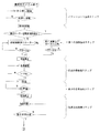
この実施例の血液成分採取装置1による血液成分採取工程(第1回目の血小板採取操作)を図4,図5ないし図10のフローチャートを用いて説明する。この実施例では、血小板採取操作を繰り返して2回行い、さらに、最終回以外の血小板採取ステップ終了後であって、返血ステップ前に、バフィーコート採取ステップを行いかつ次の採血ステップの前に遠心分離器20にこれを返還するバフィーコート返還ステップを行うようになっている。なお、流体注入用の第4のライン24および流路開閉手段87は使用されない。
【0052】
そして、図5に示すように、第1の送液ポンプ11、第2の送液ポンプ12を作動させて抗凝固剤が添加された血液を採取し、遠心分離器駆動装置10を作動させて、血液より血漿採取バッグ25内に第1の所定量の血漿を採取する第1の血漿採取ステップを行う。
最初の採血が開始されると、血液ポンプ11が所定速度(例えば、60ml/min)で採血を開始する。このとき、抗凝固剤ポンプである第2のポンプも同時に所定速度(例えば、血液ポンプ速度の1/10)で抗凝固剤(例えば、ACD−A液)を供給する。ドナーから採取された血液はACD液と混合され、第1のライン21を流れ、チャンバー、第1の流路開閉手段81を通過し、遠心分離器20に流入する。このとき、第6の流路開閉手段86、第5の流路開閉手段85、第2の流路開閉手段82,第3の流路開閉手段83,第7の流路開閉手段87は閉じており、第1の流路開閉手段81、第4の流路開閉手段84は開いている。遠心分離器20にACD加血液が供給されると、遠心分離器20に入っていた滅菌空気は第2のライン22を流れ、第4の流路開閉手段84を通過し、血小板採取バッグ26内に流入する。採血工程開始と同時に遠心分離器20が所定速度(初期ローター回転数演算値)で回転を開始し、遠心分離器20は回転しながらACD加血の供給を受けるので、分離器内では血液の遠心分離が行われ、血液は、内側から血漿層、バフィーコート層(BC層)、赤血球層の3層に分離され、分離器の容量を越えるACD加血液(約270ml)が供給されると、遠心分離器20内は完全に血液により満たされ、遠心分離器20の流出口から血漿が流出する。遠心分離器20の流出口と接続された第2のライン22に取り付けられた濁度センサ14は、ライン中を流れる流体が、空気から血漿に変わったことを検知し、制御部13は、この濁度センサ14の検知信号に基づき第4の流路開閉手段84を閉塞させ、かつ第3の流路開閉手段83を開放させて、血漿を血漿採取バッグ25内に採取する。血漿採取バッグ25は、その重量が重量センサ16により計測されており、計測された重量信号は制御部13に入力されている。このため、血漿採取バッグ25に採取された血漿重量が第1の所定量(10〜150g、例えば、30g)増加すると、制御部13は、第1の流路開閉手段81を閉塞させ、第2の流路開閉手段82を開放させて、定速血漿循環ステップに移行する。
【0053】
定速血漿循環ステップでは、採血を一時中断し、かつ、遠心分離器駆動装置10を作動させて、血漿採取バッグ25内に採取された血漿を遠心分離器20に定速にて循環させる。
定速血漿循環ステップに入ると、制御部13は、第1の流路開閉手段81の閉塞状態および第2の流路開閉手段82の開放状態を維持し、ACDポンプ12は停止し、血液ポンプ11は所定速度(60〜250ml/min、例えば、200ml/min)で作動し、血漿採取バッグ25の血漿は第2の流路開閉手段82を通って、所定速度(初期ローター回転数演算値)で回転する遠心分離器20に送られる。同時に遠心分離器20から流出してきた血漿は濁度センサ14、第3の流路開閉手段83を通って血漿採取バッグ25に流入する。定速血漿循環ステップが始まって所定時間(10〜90秒、例えば、30秒)が経過すると、制御部13は、第2の流路開閉手段82を閉じ、第1の流路開閉手段81を開いて、第2の血漿採取ステップに移行する。第1の血漿循環は、少なくとも60ml/min以上の流速で、10秒以上行うことが好ましい。
【0054】
第2の血漿採取ステップでは、第1の送液ポンプ11、第2の送液ポンプ12を作動させて抗凝固剤が添加された血液を採取し、通常、バッグ内の血漿量の増加により、光学式センサ15が、分離器のバフィーコート層を検出すると、この信号が制御部13に送られ、制御部13は、第1の流路開閉手段81を閉塞させ、第2の流路開閉手段82を開放させて、加速血漿循環ステップに移行する。
具体的には、第1の送液ポンプ11が所定速度(例えば、60ml/min)で採血を開始する。このとき、抗凝固剤ポンプである第2のポンプも同時に所定速度(例えば、血液ポンプ速度の1/10)で抗凝固剤(例えば、ACD−A液)を供給する。ドナーから採取された血液はACD液と混合され、所定速度(初期ローター回転数演算値)で回転する遠心分離器20に流入し、血漿を血漿採取バッグ25内に採取する。通常、バッグ内の血漿量の増加により、光学式センサ15が、分離器のバフィーコート層を検出すると、この信号が制御部13に送られ、制御部13は、第1の流路開閉手段81を閉塞させ、第2の流路開閉手段82を開放させて、第5の加速血漿循環ステップに移行する。第5の血漿採取ステップでは、センサ15がバフィーコート(BC界面:血漿層とバフィーコート層との界面)を検知するまで血漿を採取する。なお、この実施例の装置では、図5、図7および図9のフローチャートにも示されているように、各血漿採取ステップにおいて、BC界面の検知を行っており、もし、第1の血漿採取ステップ中にBC界面が検知されると、血漿採取を中断し、加速血漿循環ステップに移行する。
【0055】
また、この時までの採血時間および血液処理量より平均採血速度(血流速度)を計算し、所定の速度に到達しない場合には、上述したようにローター回転数を再演算し、修正ローター回転数演算値を算出する。このときに計算されたローター回転数はこの直後に行われる血小板採取およびバフィーコート採取の動作終了後より利用される。つまり、次のサイクルの採血工程よりローター回転数は変更される。
【0056】
加速血漿循環ステップでは、採血を一時中断し、かつ、遠心分離器駆動装置10を作動させて、血漿採取バッグ25内の血漿を遠心分離器20に加速させながら循環させる。このときの、血液ポンプ速度は、定速血漿循環ステップより遅く、例えば、60ml/minでスタートし、最終速度が150〜200ml/minに到達するまで、加速する。加速条件としては、1秒間毎に2〜10ml/min速度が上昇する、200ml/min到達時間約14〜70秒で行う。この循環ステップ終了後、図6の▲1▼に移行し、界面調整用の少量血漿採取ステップを行う。
【0057】
図6に示すように、界面調整用の少量血漿採取ステップでは、後に行う血小板採取工程でのバフィーコート層の位置をドナーによらず一定にするために、所定の赤血球供給量分だけ採血する。赤血球供給量は採血量をドナーのヘマトクリット値で除した値で定義され、採血量は、12ml程度が一般的である。この採血においても、第1の送液ポンプ11が所定速度(例えば、60ml/min)で採血を開始する。このとき、抗凝固剤ポンプである第2のポンプも同時に所定速度(例えば、血液ポンプ速度の1/10)で抗凝固剤(例えば、ACD−A液)を供給する。ドナーから採取された血液はACD液と混合され、所定速度(初期ローター回転数演算値)で回転する遠心分離器20に流入され、少量の血漿採取が行われる。制御部13は、設定採取量とポンプ速度より採取時間を演算し、採取時間を経過した時に、採血を終了させる。そして、制御部13は、第1の流路開閉手段81を閉塞させ、第2の流路開閉手段82を開放させて、血小板採取ステップに移行する。
【0058】
上記ステップの終了後、第1の送液ポンプ11による血漿循環速度を加速させて、遠心分離器20内より血小板を流出させ血小板を血小板採取バッグ26に採取する血小板採取ステップを行う。血小板採取ステップは、いわゆる加速工程とも呼ばれる。このステップでは、血液ポンプ速度が、この実施例では、60ml/minから200ml/minまで、所定時間(例えば、1秒間)毎に10ml/minずつ加速するように、制御部13は血液ポンプを操作し、200ml/minに到達したら、血小板採取工程が終了するまで、その速度を維持する。
【0059】
血小板採取ステップが始まると、濁度センサ14が通過する液の濁度を検知し、濁度はセンサにより電圧値として出力され、出力された信号は、制御部13に入力される。血液ポンプの速度が上昇し、おおよそ160から200ml/minに達した時点で遠心分離器20にとどまっていたバフィーコート層に含まれる血小板が流出する。血小板が流出すると濁度センサ14部分を通過する液の濁度が大きくなり、センサより出力される電圧値が0.2V低下した時点で第3の流路開閉手段83が閉じて第4の流路開閉手段84が開き、遠心分離器20から流出してくる血小板リッチな血漿を血小板採取バッグ26に採取する。濁度センサ14から出力される電圧値は、制御部13により血小板濃度に換算され、血小板採取中の血小板採取バッグ26の血小板濃度を演算する。血小板採取バッグ26の血小板濃度は一旦最高濃度に到達したのち、濃度が低下する。最高濃度に到達したことを検知した時点において、血小板採取ステップは終了し、バフィーコート採取ステップに移行する。
【0060】
バフィーコート採取ステップでは、上述の血小板採取ステップが終了すると、制御部13は、第4の流路開閉手段84を閉じ、第5の流路開閉手段85を開放させる。血漿採取バッグ25内の血漿は、血液ポンプ11により、遠心分離器20に送られ、同時に遠心分離器20から流出した液(バフィーコート層が流出したもの)は、バフィーコート採取バッグ27に流入する。バフィーコート採取ステップでは、血液ポンプ11の速度が血小板採取ステップにおける最終速度のまま維持され、かつ、遠心分離器20が所定速度または所定速度よりもわずかに高い回転速度(所定速度よりも50〜200rpm程度、例えば100rpm高い回転速度)に上げられ、これにより、遠心分離器20内よりバフィーコートを流出させバフィーコート採取バッグ27に採取する。ドナーのヘマトクリット値と血小板採取量から演算された量を採取した時点で、血液ポンプ11は停止し、全バルブが閉じ、遠心分離器20の回転が停止してバフィーコート採取ステップが終了する。
【0061】
次に、遠心分離器20内の血液を返血する返血ステップを行う。制御部13は、血液ポンプ11を逆回転させ、また、第1の流路開閉手段81を開放し、遠心分離器20内に残った赤血球層を、第1のライン21よりドナーに返血する。
これにより、1回目(初回)の血小板採取操作が終了する。
続いて、図7に示す、2回目の血小板採取操作に移行する。
最初に、図7に示すように、第1回の血小板採取操作により採取されたバフィーコートを次の血漿採取ステップの前に遠心分離器20内に返還するバフィーコート返還ステップが行われる。バフィーコート返還ステップに移行すると、制御部13は、遠心分離器20を所定回転数(初期ローター回転数演算値)で回転させ、第5の流路開閉手段85、第4の流路開閉手段84を開放し、血液ポンプ11を所定速度(デフォルトは100ml/min)で作動させる。バフィーコート採取バッグ27に入っているバフィーコートは、第5の流路開閉手段85を通り、遠心分離器20に供給される。遠心分離器20の空気は、第2のライン22、第4の流路開閉手段84を通って血小板採取バッグ26に送られる。バフィーコート採取量分だけ血液ポンプ11が回転した後、バフィーコート返還ステップは終了する。
【0062】
なお、第1回の血漿採取ステップ時における平均採血速度(血流速度)が所定の速度に到達しない場合には、図7に示し上述したように修正ローター回転数が演算され、修正ローター回転数にて、第1の血漿採取ステップ、定速血漿循環ステップ、第2の血漿採取ステップ、加速血漿循環ステップが行われ、図8に示す▲2▼に移行し、少量血漿採取ステップ、血小板採取ステップ、バフィーコート採取ステップ、返血ステップを順次行い、2回目の血小板採取操作が終了する。
【0063】
次に、図9に示す、最終回の血小板採取操作について説明する。なお、この実施例では、3回目が最終回となっているが、これに限らず、4回目以降が最終回の血小板採取操作となるものでもよい。この場合、最終回以外は、2回目の血小板採取操作(図7および図8)と同じである。
最初に、図9に示すように、第2回目の血小板採取操作により採取されたバフィーコートを次の血漿採取ステップの前に遠心分離器20内に返還するバフィーコート返還ステップを行う。
バフィーコート返還ステップに移行すると、制御部13は、遠心分離器20を所定回転数(例えば、4800rpm)で回転させ、第5の流路開閉手段85、第4の流路開閉手段84を開放し、血液ポンプ11を所定速度(デフォルトは100ml/min)で作動させる。バフィーコート採取バッグ27に入っているバフィーコートは、第5の流路開閉手段85を通り、遠心分離器20に供給される。遠心分離器20の空気は、第2のライン22、第4の流路開閉手段84を通って血小板採取バッグ26に送られる。バフィーコート採取量分だけ血液ポンプ11が回転した後、バフィーコート返還ステップは終了する。
【0064】
次に、第1の送液ポンプ11、第2の送液ポンプ12を作動させて抗凝固剤が添加された血液を採取し、遠心分離器駆動装置10を作動させて、血液より血漿採取バッグ25内に第1の所定量の血漿を採取する第1の血漿採取ステップを行う。
最初の採血が開始されると、第1の送液ポンプ11が所定速度(例えば、60ml/min)で採血を開始する。このとき、抗凝固剤ポンプである第2のポンプも同時に所定速度(例えば、血液ポンプ速度の1/10)で抗凝固剤(例えば、ACD−A液)を供給する。ドナーから採取された血液はACD液と混合され、第1のライン21を流れ、チャンバー、第1の流路開閉手段81を通過し、遠心分離器20に流入する。このとき、第6の流路開閉手段86、第5の流路開閉手段85、第2の流路開閉手段82,第3の流路開閉手段83,第7の流路開閉手段87は閉じており、第1の流路開閉手段81、第5の流路開閉手段85は開いており、遠心分離器20にACD加血液が供給されると、元々遠心分離器20に入っていた滅菌空気はラインセンサ、第5の流路開閉手段85を通ってバフィーコート採取バッグ27に流入する。採血工程開始と同時に遠心分離器20が所定速度(修正ローター回転数が演算されている場合にはその値、されていない場合には初期ローター回転数演算値)で回転を開始し、遠心分離器20は回転しながらACD加血の供給を受けるので、分離器内では血液の遠心分離が行われ、血液は、内側から血漿層、バフィーコート層(BC層)、赤血球層の3層に分離され、分離器の容量を越えるACD加血液(約270ml)が供給されると、遠心分離器20内は完全に血液により満たされ、遠心分離器20の流出口から血漿が流出する。遠心分離器20の流出口と接続された第2のライン22に取り付けられた濁度センサ14は、ライン中を流れる流体が、空気から血漿に変わったことを検知し、制御部13は、この濁度センサ14の検知信号に基づき、第5の流路開閉手段85を閉塞させ、かつ第3の流路開閉手段83を開放させて、血漿を血漿採取バッグ25内に採取する。血漿採取バッグ25は、その重量が重量センサ16により計測されており、計測された重量信号は制御部13に入力されている。このため、血漿採取バッグ25に採取された血漿重量が所定量(例えば、30g)増加すると、制御部13は、第1の流路開閉手段81を閉塞させ、第2の流路開閉手段82を開放させて、定速血漿循環ステップに移行する。
【0065】
そして、上述した定速血漿循環ステップ、第2の血漿採取ステップ、加速血漿循環ステップを行い、図10に示す▲3▼に移行し、界面調整用の少量血漿採取ステップ、血小板採取ステップ、返血ステップを順次行い、最終回の血小板採取操作が終了する。最終回と2回目との相違は、上述した定速血漿循環ステップにおける空気を流入させるバッグが相違する点と、最終回では、バフィーコート採取ステップを行うことなく返血ステップを行う点である。
【0066】
粒子懸濁液では,粒子濃度が高くなるにつれて懸濁液の見かけ粘度が高くなることが知られている。粘度が高くなると,異なる比重をもつ粒子間の沈降速度差が小さくなる。これを血小板採取工程にあてはめると、遠心分離器20内での粘度が高くなると、血小板と一緒に血小板より比重の大きい白血球が流出する確率が上昇することになる。また、採血中遠心分離器20は回転しており,遠心分離器20内の血液成分には常に遠心力がかかっており、遠心分離器20内の各血液成分は遠心力によって濃縮が進み、分離器の外側より、図3に示すように血球層、バフィーコート層、血漿層に分離される。そして、各層中の粒子は、外側から順次小さいものとなっている。
【0067】
遠心分離器20内には、いわゆる複数のケーキ層が形成され、このケーキ層が徐々に圧縮される。そして、新たに流入する全血は、遠心分離器20の最外層の血球により形成されたケーキ層より流入し、血球はこのケーキ層により捕捉され他の成分は通過し、バフィーコート層、血漿層に移行する。しかし、血球ケーキ層、バフィーコートケーキ層が過剰に圧縮されると各層内の微粒子間の隙間が小さくなり、血小板が、血球ケーキ層もしくはバフィーコートケーキ層に捕捉されることが起きる。このため、血小板の採取効率が低下するものと予想する。
【0068】
しかし、本発明では、血漿採取ステップを区分し、1回目の血漿採取ステップ時間を短くできるとともに、2回目の血漿採取後に、加速血漿循環ステップを行うことにより、上述のケーキ層の圧縮の進行が進みにくい。特に、加速血漿循環ステップとすることにより、最終到達循環速度を高いものとしても、ケーキ層の圧縮が生じにくいばかりか、赤血球層に埋もれた血小板を舞上げ、BC層に取り込むことができる。また、BC層自体も舞い上がるため、BC層内の血小板と白血球との分離と整列を促進する。これらにより、血小板の採取効率が向上する。
【0069】
次に、図11に示す実施例の血液成分採取装置100について説明する。この血液成分採取装置100は、ヘマトクリット値測定機能を備える以外は、上述した血液成分採取装置1と同じであり、同じ部分については、同じ符号を付し、説明は上述の血液成分採取装置1を参照する。
具体的には、血液成分採取装置100は、ヘマトクリット値測定機能を構成するセンサ101を備え、このセンサ101は、制御部13と電気的に接続されている。センサ101としては、例えば、800nmの波長の赤外線を用いてその吸光度を利用したもの(例えば、800nmの赤外線の照射と反射光もしくは透過光を受光する機能を備えたもの)が使用できる。また、特開昭62−265563号公報に提案されているようなものでもよい。センサ101は、正確なヘマトクリット値の測定のために、第1のライン21であり、かつ抗凝固剤注入のための第3のライン23との接続部21cより採血針29側の位置に設けられている。具体的には、センサ101は、第1のライン21であり、抗凝固剤添加ラインである第3のライン23との接続部である分岐管21cと採血針29との間(分岐管の付近)に位置している。このため、抗凝固剤が添加される前の血液のヘマトクリット値を測定する。
【0070】
また、センサ101を直接制御部と接続する形態のものではなく、センサ101とその検知結果よりヘマトクリット値を算出するヘマトクリット値測定本体部を備え、このヘマトクリット値測定本体部より、算出されたヘマトクリット値が制御部13に入力されるように、ヘマトクリット値測定本体部と制御部が接続されたものでもよい。
そして、血液成分採取装置100では、制御部13は、上記の機能により測定されたヘマトクリット値を用いて、そのヘマトクリット値に適したローター回転数を演算するローター回転数演算機能および血漿採取ステップ時、血漿採取・定速循環ステップ時、第2の血漿採取ステップ時および血漿採取・加速循環ステップ時にローター回転数演算機能により演算されたローター回転数にてローターを回転させるように遠心分離器駆動装置を制御する。また、上述した実施例と同様に、第1回の血漿採取ステップ時における平均採血速度(血流速度)が所定の速度に到達しない場合には、上述したように修正ローター回転数が演算され、修正ローター回転数にて、第2回以降の血漿採取ステップにおける血漿採取ステップ時、血漿採取・定速循環ステップ時、第2の血漿採取ステップ時および血漿採取・加速循環ステップ時にローター回転数演算機能により再度算出された修正ローター回転数にてローターを回転させるように遠心分離器駆動装置を制御する。
【0071】
この実施例の血液成分採取装置100による血液成分採取工程(第1回目の血小板採取操作)を図12および図13のフローチャートを用いて説明する。この実施例でも、血小板採取操作を繰り返して2回行い、さらに、最終回以外の血小板採取ステップ終了後であって、返血ステップ前に、バフィーコート採取ステップを行いかつ次の採血ステップの前に遠心分離器20にこれを返還するバフィーコート返還ステップを行うようになっている。
まず、最初に、第3のライン23と採血針29を抗凝固剤でプライミングし、その後ドナーに穿刺針を穿刺する。
【0072】
そして、第1の送液ポンプ11、第2の送液ポンプ12を作動させることにより、第1のライン21に供血者より血液が流入されるとともに、センサ101により検知されたヘマトクリット値関連信号は、制御部13に送られ、制御部13は、このヘマトクリット値関連信号を用いて、ヘマトクリット値を算出する。さらに、算出されたヘマトクリット値より、演算部は、適正ローター回転数を演算する。遠心分離器駆動装置10はローターを演算値で回転させて、血液より血漿採取バッグ25内に第1の所定量の血漿を採取する第1の血漿採取ステップを行う。
【0073】
最初の採血が開始されると、血液ポンプ11が所定速度(例えば、60ml/min)で採血を開始する。このとき、抗凝固剤ポンプである第2のポンプも同時に所定速度(例えば、血液ポンプ速度の1/10)で抗凝固剤(例えば、ACD−A液)を供給する。ドナーから採取された血液はACD液と混合され、第1のライン21を流れ、チャンバー、第1の流路開閉手段81を通過し、遠心分離器20に流入する。このとき、第6の流路開閉手段86、第5の流路開閉手段85、第2の流路開閉手段82,第3の流路開閉手段83,第7の流路開閉手段87は閉じており、第1の流路開閉手段81、第4の流路開閉手段84は開いている。遠心分離器20にACD加血液が供給されると、遠心分離器20に入っていた滅菌空気は第2のライン22を流れ、第4の流路開閉手段84を通過し、血小板採取バッグ26内に流入する。採血工程開始と同時に遠心分離器20のローターが演算値(例えば、4800rpm)で回転を開始し、遠心分離器20は回転しながらACD加血の供給を受けるので、分離器内では血液の遠心分離が行われ、血液は、内側から血漿層、バフィーコート層(BC層)、赤血球層の3層に分離され、分離器の容量を越えるACD加血液(約270ml)が供給されると、遠心分離器20内は完全に血液により満たされ、遠心分離器20の流出口から血漿が流出する。遠心分離器20の流出口と接続された第2のライン22に取り付けられた濁度センサ14は、ライン中を流れる流体が、空気から血漿に変わったことを検知し、制御部13は、この濁度センサ14の検知信号に基づき第4の流路開閉手段84を閉塞させ、かつ第3の流路開閉手段83を開放させて、血漿を血漿採取バッグ25内に採取する。血漿採取バッグ25は、その重量が重量センサ16により計測されており、計測された重量信号は制御部13に入力されている。このため、血漿採取バッグ25に採取された血漿重量が第1の所定量(10〜150g、例えば、20g)増加すると、制御部13は、第1の流路開閉手段81を閉塞させ、第2の流路開閉手段82を開放させて、定速血漿循環ステップに移行する。
【0074】
定速血漿循環ステップ移行後は、上述した実施例1と同じである。そして、第2の血漿採取ステップ終了後、この時までの採血時間および血液処理量より平均採血速度(血流速度)を計算し、所定の速度に到達しない場合には、上述したようにローター回転数を再演算する。このときに計算されたローター回転数は後に行われる血小板採取およびバフィーコート採取の動作終了後より利用される。つまり、次のサイクルの採血工程よりローター回転数は変更される。そして、加速血漿循環ステップが行われ、加速血漿循環ステップ終了後には、図6の▲1▼に移行し、界面調整用の少量血漿採取ステップを行う。これ以降は、図6ないし図10に示すフローチャートならびに図6ないし図10を用いて上述した実施例と同じである。
【0075】
そして、この実施例では、図6ないし図10のように行われるため、当初に演算されたローター回転数(初期ローター回転数演算値)もしくは修正ローター回転数演算値により、必要時にローターの回転数が制御される。また、2回目の採血時にも、ヘマトクリット値を測定し、新たに測定されたヘマトクリット値を用いるとともに血流速度を考慮して、再度ローターの回転速度を演算し、2回目の血漿採取ステップ以降は、新たに演算されたローター回転速度を用いるものとしてもよい。さらに、3回目以降の血漿採取ステップがある場合には、その都度ヘマトクリット値を測定し、新たに測定されたヘマトクリット値を用いるとともに血流速度を考慮して、新たに演算されたローター回転速度(最新のローター回転数演算値)を用いるものとしてもよい。
【0076】
次に、本発明の他の実施例の血液成分採取装置について説明する。この血液成分採取装置は、遠心分離器を用いたヘマトクリット値測定機能を備え、この機能を用いて、最初の血漿採取ステップ時にヘマトクリット値を測定し、測定されたヘマトクリット値を用いて、このヘマトクリット値に適したローター回転数を演算するローター回転数演算機能および第2回目の血漿採取ステップ時および血漿採取・加速循環ステップ時にローター回転数演算機能により演算されたローター回転数にてローターを回転させるように遠心分離器駆動装置を制御するものである。基本的構成は、図4に示す血液成分採取装置1と同じである。
【0077】
遠心分離器を用いたヘマトクリット値の測定方法としては、例えば、以下の方法がある。光学式センサ15としては、遠心分離器20の外周面に沿って上下方向に走査し得る光学式センサが用いられる(具体的には、5つの光センサが垂直方向に直線状に配列されている)。そして、これらセンサを用いて、遠心分離器20のどの位置に血球界面が来ているかを測定する。測定された境界面信号は、制御部にて、xi(i=0〜n、nは光センサの分解能力によって定まる整数)のデータとして記憶される。なお、x0は、界面が検知されない状態であり、xnは、遠心分離器20内がすべて血球で満たされた状態である。遠心分離器形状、容積は既知であり、採血速度(脱血速度)、抗凝固剤注入速度、ローターも回転数を一定のものとすれば、xiとヘマトクリット値(Hct)間は、下記の相関式
Hct(%)=F(xi)
が成り立つとともに、制御部はこの相関式を記憶している。このため、制御部は、上記のセンサ15より得られる信号xiを用いたヘマトクリット値演算機能を備えている。なお、上記相関式においては、供血者からの脱血速度および抗凝固剤注入速度を考慮した補正が行われており、制御部により演算される値は、ACD加血のヘマトクリット値ではなく、ほぼ実際のヘマトクリット値である。
【0078】
この実施例の血液成分採取装置による血液成分採取工程(第1回目の血小板採取操作)を図13のフローチャートを用いて説明する。この実施例では、血小板採取操作を繰り返して2回行い、さらに、最終回以外の血小板採取ステップ終了後であって、返血ステップ前に、バフィーコート採取ステップを行いかつ次の採血ステップの前に遠心分離器20にこれを返還するバフィーコート返還ステップを行うようになっている。
最初に、第3のライン23と採血針29を抗凝固剤でプライミングし、その後ドナーに穿刺針を穿刺する。
第1の送液ポンプ11、第2の送液ポンプ12を作動させて抗凝固剤が添加された血液を採取し、遠心分離器駆動装置10は、制御部が記憶する設定回転数にて、ローターを回転させて、血液より血漿採取バッグ25内に第1の所定量の血漿を採取する第1の血漿採取ステップを行う。
【0079】
最初の採血が開始されると、血液ポンプ11が所定速度(例えば、60ml/min)で採血を開始する。このとき、抗凝固剤ポンプである第2のポンプも同時に所定速度(例えば、血液ポンプ速度の1/10)で抗凝固剤(例えば、ACD−A液)を供給する。ドナーから採取された血液はACD液と混合され、第1のライン21を流れ、チャンバー、第1の流路開閉手段81を通過し、遠心分離器20に流入する。このとき、第6の流路開閉手段86、第5の流路開閉手段85、第2の流路開閉手段82,第3の流路開閉手段83,第7の流路開閉手段87は閉じており、第1の流路開閉手段81、第4の流路開閉手段84は開いている。遠心分離器20にACD加血液が供給されると、遠心分離器20に入っていた滅菌空気は第2のライン22を流れ、第4の流路開閉手段84を通過し、血小板採取バッグ26内に流入する。採血工程開始と同時に遠心分離器20のローターが設定値(例えば、4800rpm)で回転を開始し、遠心分離器20は回転しながらACD加血の供給を受ける。
そして、遠心分離器20に取り付けられた光学式センサ15を用いて、ヘマトクリット値を演算する。そして、演算されたヘマトクリット値を用いて、ローター適正回転数をさらに演算する。
【0080】
また、遠心分離器20内では、血液の遠心分離が行われ、血液は、内側から血漿層、バフィーコート層(BC層)、赤血球層の3層に分離され、分離器の容量を越えるACD加血液(約270ml)が供給されると、遠心分離器20内は完全に血液により満たされ、遠心分離器20の流出口から血漿が流出する。遠心分離器20の流出口と接続された第2のライン22に取り付けられた濁度センサ14は、ライン中を流れる流体が、空気から血漿に変わったことを検知し、制御部13は、この濁度センサ14の検知信号に基づき第4の流路開閉手段84を閉塞させ、かつ第3の流路開閉手段83を開放させて、血漿を血漿採取バッグ25内に採取する。血漿採取バッグ25は、その重量が重量センサ16により計測されており、計測された重量信号は制御部13に入力されている。このため、血漿採取バッグ25に採取された血漿重量が第1の所定量(10〜150g、例えば、20g)増加すると、制御部13は、第1の流路開閉手段81を閉塞させ、第2の流路開閉手段82を開放させて、定速血漿循環ステップに移行する。
【0081】
定速血漿循環ステップでは、採血を一時中断し、かつ、遠心分離器駆動装置10を作動させて遠心分離器20のローターの設定値での回転を維持し、血漿採取バッグ25内に採取された血漿を遠心分離器20に定速にて循環させる。
定速血漿循環ステップに入ると、制御部13は、第1の流路開閉手段81の閉塞状態および第2の流路開閉手段82の開放状態を維持し、ACDポンプは停止し、血液ポンプ11は所定速度(60〜250ml/min、例えば、200ml/min)で作動し、血漿採取バッグ25の血漿は第2の流路開閉手段82を通って、設定値(例えば4800rpm)で回転している遠心分離器20に送られる。同時に遠心分離器20から流出してきた血漿は濁度センサ14、第3の流路開閉手段83を通って血漿採取バッグ25に流入する。定速血漿循環ステップが始まって所定時間(10〜90秒、例えば、30秒)が経過すると、制御部13は、第2の流路開閉手段82を閉じ、第1の流路開閉手段81を開いて、第2の血漿採取ステップに移行する。第1の血漿循環は、少なくとも60ml/min以上の流速で、10秒以上行うことが好ましい。
【0082】
第2の血漿採取ステップでは、第1の送液ポンプ11、第2の送液ポンプ12を作動させて抗凝固剤が添加された血液を採取し、バッグ内の血漿量の増加により、光学式センサ15が、分離器のバフィーコート層を検出すると、この信号が制御部13に送られ、制御部13は、第1の流路開閉手段81を閉塞させ、第2の流路開閉手段82を開放させて、加速血漿循環ステップに移行する。
具体的には、第1の送液ポンプ11が所定速度(例えば、60ml/min)で採血を開始する。このとき、抗凝固剤ポンプである第2のポンプも同時に所定速度(例えば、血液ポンプ速度の1/10)で抗凝固剤(例えば、ACD−A液)を供給する。ドナーから採取された血液はACD液と混合され、設定値(例えば、4800rpm)でローターが回転する遠心分離器20に流入し、血漿を血漿採取バッグ25内に採取する。通常、バッグ内の血漿量の増加により、光学式センサ15が、分離器のバフィーコート層を検出すると、この信号が制御部13に送られ、制御部13は、第1の流路開閉手段81を閉塞させ、第2の流路開閉手段82を開放させて、加速血漿循環ステップに移行する。血漿採取ステップでは、センサがバフィーコート(BC界面:血漿層とバフィーコート層との界面)を検知するまで血漿を採取する。なお、この実施例の装置では、図12、図7および図9のフローチャートにも示されているように、第1から最終前の各血漿採取ステップにおいても、BC界面の検知を行っており、もし、これら第1から最終前の血漿採取ステップ中にBC界面が検知されると、血漿採取を中断し、加速血漿循環ステップに移行する。
【0083】
この時までの採血時間および血液処理量より平均採血速度(血流速度)を計算し、所定の速度に到達しない場合には、上述したようにローター回転数を再演算する。このときに計算されたローター回転数は後に行われる血小板採取およびバフィーコート採取の動作終了後より利用される。つまり、次のサイクルの採血工程よりローター回転数は変更される。
そして、加速血漿循環ステップでは、採血を一時中断し、かつ、遠心分離器駆動装置10を作動させて遠心分離器20のローターの設置値での回転を維持し、血漿採取バッグ25内の血漿を遠心分離器20に加速させながら循環させる。このときの血液ポンプ速度は、定速血漿循環ステップより遅く、例えば、60ml/minでスタートし、最終速度が200ml/minに到達するまで、加速する。加速条件としては、1秒間毎に6.7ml/min速度が上昇する、200ml/min到達時間約21秒で行う。この循環ステップ終了後、図6の▲1▼に移行し、界面調整用の少量血漿採取ステップを行う。
【0084】
これ以降は、図6ないし図10に示すフローチャートならびに図6ないし図10を用いた上述した実施例1と同じとなり、遠心分離器20のローターは、第1回目のステップと異なり、第1回目の血漿採取操作における血流速度が所定値より大きい場合には、当初に測定されたヘマトクリット値より演算された通常ローター回転数演算値により、また、第1回目の血漿採取操作における血流速度が所定値以下の場合には、測定されたヘマトクリット値を用いるとともに血流速度を考慮して算出された修正ローター回転数演算値によりローターの回転が行われる。さらに、3回目以降の血漿採取ステップがある場合には、2回目の血漿採取ステップ時にも遠心分離器を用いてヘマトクリット値を測定し、この測定値を用いて通常ローター回転数演算値もしくは修正ローター回転数演算値を新たに演算し、この演算値を用いてローター回転速度(最新のローター回転数演算値数)を用いて、3回目以降の血漿採取ステップを行うものとしてもよい。
【0085】
【実施例】
図4に示すような回路構成で、ACDポンプ12と血液ポンプ11の2台で構成される装置を作製し、血小板採取性能を比較した。ドナーは同じドナーを用い、2週間以上間隔をあけて比較実験を行った。以下に評価した動作フローを比較したものを示した。n=2例で比較した。得られた濃厚血小板血漿の血小板数、白血球数をSysmex(R)NE−6000で測定した。但し、SysmexのWBC測定下限は0.1×10²[Cells/muL]なので、測定下限を下回ったサンプルではNageotte[1:9]法を用いて測定した。血小板採取量は40mlとした。
【0086】
(実施例1)
血小板採取操作は、3回とし、上述の方法により行った。なお、採血速度は、40ml/min、血漿総量が30gとなった後に行う第1循環条件(200ml/min,30sec)、BC界面検出後に行う第2循環条件(初速60ml/min,到達速度170ml/min、加速条件5ml/min/sec、加速時間22sec)、血小板採取時の加速条件(10ml/min/sec)、血小板採取速度(200ml/min,血小板採取所定濃度まで)、バフィーコート採取速度(195ml/min,30ml)とし、2回目および3回目は、採血前にバフィーコートを遠心分離器に返還し、3回目には、バフィーコート採取を行わなかった。
上述した下記の相関関係式
y=0.0667x3−8.7619x2+391.9x−1277.4−D
かつ
y≧4400
より、修正ローター回転数演算値を算出したところ、最低ローター回転数の4400rpm(Hct=35%)となった。
【0087】
(比較例)
装置としては、実施例と同じものを用いた。血小板採取操作は、3回とし、採血速度は、40ml/min、血漿総量が30gとなった後に行う第1循環条件(200ml/min,30sec)、BC界面検出後に行う第2循環条件(初速60ml/min,到達速度170ml/min、加速条件5ml/min/sec、加速時間22sec)、血小板採取時の加速条件(10ml/min/sec)、血小板採取速度(200ml/min,血小板採取所定濃度まで)、バフィーコート採取速度(195ml/min,30ml)とし、2回目および3回目は、採血前にバフィーコートを遠心分離器に返還し、3回目には、バフィーコート採取を行わなかった。遠心回転数は4800rpm(Hct=35%)とした。
そして、採取された実施例および比較例の濃厚血小板血漿の血小板濃度、白血球濃度、血液処理量は以下の通りである。
【0088】
【表1】

【表2】
【表3】
【発明の効果】
本発明の血液成分採取装置では、制御部は、供血者の採血時の血流速度によって、前記遠心分離器のローターの遠心回転数を制御する機能を備えている。例えば、供血者の採血時の血流速度を考慮してローター回転数を変更させることにより、低血流量の供血者に場合においてパッキングと呼ばれる過剰遠心による分離血液成分層の過剰圧縮現象を起こすことを防止できる。このようなパッキングが生じると、血小板層も圧縮されるため血小板の採取が困難となり採取効率が悪くなる。また、逆に、高ヘマトクリット値の供血者の場合では、遠心不足による分離不十分な状態を起こすことを防止できる。このような分離不十分な状態が生じると、血小板層内に位置しない多くの血小板が、血球層もしくは血漿中に存在し、採取効率が悪くなる。しかし、本発明の装置では、上記のようなパッキング現象も分離不十分状態の発生も極めて少なくなり、効率のよい血小板採取を行うことができる。
【図面の簡単な説明】
【図1】図1は、本発明の血液成分採取装置に使用される血液成分採取回路の構成例を示す平面図である。
【図2】図2は、図1の血液成分採取回路のカセットハウジング部分の平面図である。
【図3】図3は、血液成分採取回路に使用される遠心分離器に駆動装置が装着された状態の部分破断断面図である。
【図4】図4は、血液成分採取回路を装着した状態の本発明の血液成分採取装置の一実施例の概念図である。
【図5】図5は、本発明の血液成分採取装置の作用を説明するためのフローチャートである。
【図6】図6は、本発明の血液成分採取装置の作用を説明するためのフローチャートである。
【図7】図7は、本発明の血液成分採取装置の作用を説明するためのフローチャートである。
【図8】図8は、本発明の血液成分採取装置の作用を説明するためのフローチャートである。
【図9】図9は、本発明の血液成分採取装置の作用を説明するためのフローチャートである。
【図10】図10は、本発明の血液成分採取装置の作用を説明するためのフローチャートである。
【図11】図11は、血液成分採取回路を装着した状態の本発明の血液成分採取装置の他の実施例の概念図である。
【図12】図12は、本発明の血液成分採取装置の作用を説明するためのフローチャートである。
【図13】図13は、本発明の血液成分採取装置の作用を説明するためのフローチャートである。
【符号の説明】
1 血液成分採取装置
2 血液成分採取回路
10 遠心分離器駆動装置
11 第1の送液ポンプ
12 第2の送液ポンプ
13 制御部
14 濁度センサ
15 光学式センサ
16 重量センサ
20 遠心分離器
21 第1のライン
22 第2のライン
23 第3のライン
24 第4のライン
25 血漿採取バッグ
26 血小板採取バッグ
29 採血針
100 血液成分採取装置[0001]
BACKGROUND OF THE INVENTION
The present invention relates to a blood component collection device for separating a predetermined blood component from blood.
[0002]
[Prior art]
At the time of blood collection, for the purpose of effective use of blood and reduction of burden on blood donors, the blood sample is separated into each blood component by centrifugation, etc., and only the components necessary for the transfuser are collected. Ingredients are collected to return the ingredients to the blood donor.
In such component blood collection, when obtaining a platelet preparation, blood collected from a blood donor is introduced into a blood component collection circuit, and a centrifuge called a centrifuge bowl installed in the blood component collection circuit is used to obtain plasma, white blood cells, The platelets and red blood cells are separated into four components, and the platelets are collected in a container to obtain a platelet preparation, and the remaining plasma, white blood cells and red blood cells are returned to the blood donor.
[0003]
As a method for collecting platelets, for example, there is a method disclosed in JP-T-8-509403. In Japanese Patent Publication No. 8-509403, the first method is to add a liquid to whole blood at a predetermined flow rate and send it to a centrifuge bowl while diluting. The whole blood is sent to the centrifuge bowl and centrifuged to obtain a low density component. After separating the medium-density component and the high-density component and taking out the low-density component into the first container, the circuit is switched to circulate the low-density component at the first flow rate (constant speed), and the inside of the centrifuge bowl. A second method is disclosed in which the medium density component is taken out while the density component region is expanded and recirculated at the second flow rate (acceleration).
[0004]
[Problems to be solved by the invention]
The number of centrifugal revolutions is constant regardless of the donor, and when the blood flow rate at the time of blood collection is low, the blood collection time becomes longer in relation to the increase in blood removal volume, and the concentration of blood cell components inside the centrifuge bowl further proceeds. In some cases (high concentration), platelet collection did not work well.
Accordingly, an object of the present invention is to provide a blood component collection device that has high platelet collection efficiency and can obtain a high-concentration platelet-containing solution.
[0005]
[Means for Solving the Problems]
The object to achieve the above object is to have a rotor having a blood storage space inside, an inlet and an outlet communicating with the blood storage space, and blood introduced from the inlet by the rotation of the rotor. A centrifuge for centrifuging, a first line for connecting a blood collection needle or blood collection device connection portion and an inflow port of the centrifuge, and a first line connected to the outflow port of the centrifuge. 2, a third line for injecting an anticoagulant connected to the first line, a first tube connected in the middle of the first line, and the second line. A blood component collection device comprising a blood component collection circuit comprising a plasma collection bag having a second tube and a platelet collection bag connected to the second line, wherein the blood component collection device comprises the centrifuge Separation A centrifuge drive device for rotating the rotor, a hematocrit value input unit or a hematocrit value measurement function and a control unit, and the control unit calculates a rotor rotation number, and a blood donor And when the blood flow velocity calculated by the blood flow velocity calculation function is greater than a certain value, the rotor rotation speed calculation function is configured to input or measure the hematocrit value. The rotor rotation speed suitable for the hematocrit value is calculated, and when the blood flow velocity calculated by the blood flow velocity calculation function is a predetermined value or less, the rotor rotation speed calculation function is input or measured. Calculating a rotational speed lower than the rotor rotational speed suitable for the hematocrit value calculated using the hematocrit value by a predetermined value; It is to have a blood component collection apparatus comprising a function of controlling the centrifugal separator drive unit to rotate the rotor at a rotor rotational speed Ne that is calculated by the rotation speed computing function.
[0006]
In addition, the blood component collection device is disposed on the centrifuge side from a connection portion between the first line and the first tube, and includes a first liquid feeding pump for the first line, A second liquid feeding pump for
[0007]
The control unit is configured to perform the first liquid feeding pump and the second liquid feeding after the end of the plasma collection / circulation step and before accelerating the plasma circulation speed by the first liquid feeding pump. Collecting blood to which an anticoagulant has been added by operating a pump, and operating the centrifuge drive device to perform a plasma collection step of collecting a predetermined amount of plasma from the blood into the plasma collection bag It is preferable that The control unit controls the plasma collection / circulation step to be performed twice. In the first plasma collection / circulation step, the plasma in the plasma collection bag is sent to the centrifuge at a constant speed. In the second plasma collection / circulation step, there is a plasma collection / acceleration circulation step in which the plasma in the plasma collection bag is circulated while being accelerated by the centrifuge. It is preferable that it is controlled to be performed. In addition, the blood component collection circuit includes a buffy coat collection bag connected to the second line, and the control unit performs the centrifugation after the platelet collection step and before the blood return step. It is preferable to perform a buffy coat collecting step of discharging the buffy coat from the inside of the vessel and collecting the buffy coat in the buffy coat collection bag.
[0008]
The control unit may return the collected buffy coat to the centrifuge before the next plasma collection / circulation step when a platelet collection operation is further performed after the buffy coat collection step is completed. It is preferable to control the first liquid feeding pump and the plurality of flow path opening / closing means so as to perform the coat returning step.
And the said control part is equipped with the minimum rotor rotation speed memory | storage function,SaidWhen the rotor rotational speed calculated by the rotor rotational speed calculation function is larger than the minimum rotor rotational speed, the centrifuge drive device is controlled to rotate the rotor at the calculated rotor rotational speed,With the rotor speed calculation functionWhen the calculated rotor rotational speed is smaller than the minimum rotor rotational speed, it is preferable to have a function of controlling the centrifuge drive device to rotate the rotor at the minimum rotor rotational speed.
[0009]
The hematocrit value measuring function is a hematocrit value measuring sensor provided at a position closer to the blood collection needle than the connection with the third line for injecting the anticoagulant into the first line. May be. Further, the hematocrit value measuring function may be a hematocrit value measuring function using a centrifuge during the first plasma collection step.
[0010]
DETAILED DESCRIPTION OF THE INVENTION
The blood component collection device of the present invention will be described with reference to the embodiments shown in the drawings.
FIG. 1 is a plan view showing a configuration example of a blood component collection circuit used in the blood component collection device of the present invention. FIG. 2 is a plan view of a cassette housing portion of the blood component collection circuit of FIG. FIG. 3 is a partially broken cross-sectional view of a centrifuge used in a blood component collection circuit in a state where a drive device is mounted, and FIG. 4 is a blood component collection of the present invention in a state where the blood component collection circuit is mounted. It is a conceptual diagram of one Example of an apparatus.
The blood
[0011]
The blood
Since this blood component collection device is composed of two pumps, the device can be miniaturized.
[0012]
First, the blood
The blood
[0013]
A known metal needle is used as the
[0014]
The
[0015]
One end of the
One end of the
The
[0016]
As a constituent material of the tube used for forming the above-described first to
[0017]
Each of the
[0018]
Further, as the sheet material of each of the
In addition, as a sheet material used for the
[0019]
The main part of the blood
[0020]
Further, the
[0021]
Further, the aforementioned branch connector is fixed to the inner surface of the
The blood
[0022]
The
[0023]
The
[0024]
Next, the blood
The blood
[0025]
In this embodiment, the blood component collection device includes a hematocrit value input unit. The
[0026]
Further, the
Specifically, the blood component collection device has a centrifuge drive device for rotating the rotor of the centrifuge and a hematocrit value input unit or a hematocrit value measurement function, and the control unit calculates the rotor rotation speed. If the blood flow velocity calculated by the blood flow velocity calculation function is greater than a certain value, the blood flow velocity calculation function at the time of blood collection by the donor, and the minimum rotor rotation speed memory function are provided. The rotor speed calculation function calculates the rotor speed suitable for the hematocrit value using the input or measured hematocrit value, and the blood flow speed calculated by the blood flow speed calculation function is below a certain value. The rotor speed calculation function is more than the rotor speed suitable for the hematocrit value calculated using the input or measured hematocrit value. If the rotor speed calculated by the rotor speed calculation function is larger than the minimum rotor speed, the centrifuge is operated to rotate the rotor at the calculated rotor speed. The drive device is controlled, and when the calculated rotor rotation speed is smaller than the minimum rotor rotation speed, the centrifuge drive device is controlled to rotate the rotor at the minimum rotor rotation speed.
[0027]
More specifically, the
[0028]
y = 40x + 3000
y = -0.94505x2+ 110.18x + 1744
y = 0.0667x3-8.7619x2+ 391.9x-1277.4
[0029]
In any of these examples of appropriate relational expression data, the tendency is that the lower the hematocrit value, the lower the appropriate rotor speed, and the higher the hematocrit value, the higher the appropriate rotor speed.
When the hematocrit value (x) is input, the appropriate rotor rotational speed (y) is calculated from the above-described stored appropriate relational expression data of the hematocrit value and the rotor rotational speed. Then, when necessary (at the time of plasma collection / circulation step described later, at the time of second plasma collection / circulation step), the centrifuge drive device rotates the rotor at the rotor speed calculated by the rotor speed calculation function. To control.
[0030]
In this way, by changing the rotor rotation speed in accordance with the hematocrit value, for example, in the case of a donor with a low hematocrit value, it is possible to prevent the excessive compression phenomenon of the separated blood component layer due to excessive centrifugation called packing. it can. When such packing occurs, the platelet layer is also compressed, so that it is difficult to collect platelets, resulting in poor collection efficiency. Conversely, in the case of a donor with a high hematocrit value, it is possible to prevent an insufficient separation due to insufficient centrifugation. When such a state of insufficient separation occurs, many platelets not located in the platelet layer are present in the blood cell layer or plasma, and the collection efficiency is deteriorated. However, in the apparatus of the present invention, the occurrence of the packing phenomenon as described above and the insufficient separation state are extremely reduced, and efficient platelet collection can be performed.
[0031]
Furthermore, the
[0032]
The
VDAVE= BPV ÷ (T1-T2) (
T1: Time from the start of blood collection to the start of the acceleration process immediately before platelet collection
T2: Total time during which blood collection is stopped and blood collection is stopped
BPV: Total amount of blood processed (collected) in that cycle
Average blood collection rate: VDAVE
[0033]
And the average blood collection speed calculated by the blood flow velocity calculation function: VDAVEIs a low flow rate below a certain flow rate (specifically, 40 ml / min or less), the rotor rotational speed is calculated by the following formula.
N (corrected rotor speed) = y−D
And
N (corrected rotor speed) ≧ 4400
D is an arbitrary fixed value (predetermined value), preferably 100 to 800, for example, 400. That is, average blood collection speed: VDAVEIs equal to or less than a constant flow rate, the value obtained by subtracting a predetermined value (400 rpm) from the normal calculation value is output as the adjusted rotor rotation speed as long as it is 4400 rpm or more, thereby rotating the rotor.
[0034]
The blood flow velocity is not based on the above calculation, but a sensor (for example, an electromagnetic flow meter) for measuring the flow velocity of blood flowing through the blood component collection circuit (for example, the first line 21). May be provided and measured. In this case, if the measured blood flow velocity is less than or equal to a predetermined value from the middle of the first plasma collection step, the rotational speed of the rotor is calculated again, and the rotor speed is calculated based on the calculated corrected rotational speed of the rotor. The rotation may be controlled.
[0035]
In the above description, when the blood flow rate is low, the predetermined value (400 rpm) is subtracted from the normal calculation value. However, the predetermined value (fixed value) is not changed, but changes depending on the calculated blood flow rate. It may be a thing. As an arithmetic expression in such a case,
N = y− (1 / VDAVE) × E
And
N (corrected rotor speed) ≧ 4400
It is good. E is an arbitrary fixed value, preferably 4000-32000, for example 16000.
[0036]
Further, the control unit is not limited to the one that calculates y (rotor rotational speed) once and calculates the corrected rotor rotational speed N by using it once as described above, but is calculated by the blood flow rate calculation function. Average blood collection rate: VDAVEStores one of the following low-flow-rate rotor rotational speed calculation formulas used when is a low flow rate of a specific flow rate or less (specifically, 40 ml / min or less). Also good.
y = 40x + 3000-D and y ≧ 4400
y = -0.94505x2+ 110.18x + 1744-D and y ≧ 4400
y = 0.0667x3-8.7619x2+ 391.9x-1277.4-D
And y ≧ 4400
[0037]
Further, the flow path opening / closing means 81, 82, 83, 84, 85, 86, 87 are all connected to the control unit, and their opening / closing is controlled by the
[0038]
The first flow path opening / closing means 81 is provided to open and close the
[0039]
As shown in FIG. 3, the
[0040]
In addition, on the inner wall of the rotor rotation
[0041]
The
The first
[0042]
The control unit is configured to collect blood to which an anticoagulant has been added, to separate the collected blood and to collect the separated plasma in a plasma collection bag, and to collect a plasma collection bag collected by the plasma collection step. At least one plasma collection / circulation step consisting of a plasma circulation step for circulating the plasma in the centrifuge, and after completion of the plasma collection / circulation step, the plasma circulation rate by the first liquid feeding pump is accelerated. A platelet collecting step for allowing platelets to flow out of the centrifuge and collecting the platelets in a platelet collection bag; and a blood return step for returning the blood in the centrifuge after the completion of this platelet collection step. is there.
[0043]
Specifically, the
[0044]
Thus, during one platelet collection operation, blood plasma collection is temporarily stopped and the plasma recirculation step of recirculating the collected plasma to the centrifuge is performed at least twice, and the latter plasma recirculation step Accelerated circulation suppresses excessive compression of the blood cell layer and buffy coat layer (BC layer) in the centrifuge, so that platelets buried in the erythrocyte layer are soared and taken into the BC layer. Can do. In addition, since the BC layer itself rises, the separation and alignment of platelets and leukocytes in the BC layer are promoted. For this reason, it is possible to obtain a platelet-containing liquid (concentrated platelet plasma) with little white blood cell contamination and high platelet collection efficiency.
[0045]
Further, the
[0046]
Furthermore, the
Then, after the buffy coat collecting step is completed, the first
[0047]
The platelet collection operation will be described more specifically.
First, blood cell component measurement is performed in advance using sampling blood collected from a blood donor immediately before the operator starts component blood collection. By inputting the blood donor's hematocrit value measured at this time into the apparatus, the control unit calculates the optimum rotor speed (initial rotor speed). Then enter any other parameters you need. Then, the
[0048]
An anticoagulant is added to whole blood at a predetermined ratio (1/8 to 1/20, specifically 1/10 with respect to whole blood), and a predetermined rate (250 ml / min or less; preferably 150 to 40 ml / min. or less, specifically 60 ml / min or less) to the
[0049]
Then, again, an anticoagulant is added to the whole blood at a predetermined ratio (1/8 to 1/20, specifically 1/10 with respect to the whole blood), and a predetermined rate (250 ml / min or less; preferably, 150 to 40 ml / min or less, specifically, 60 ml / min or less) and sent to the
[0050]
The average blood collection speed (blood flow speed) is calculated from the blood collection time and blood throughput up to this time, and if the predetermined speed is not reached, the rotor rotational speed is recalculated as described above. The rotor rotational speed calculated at this time is used after completion of the platelet collection and buffy coat collection operations performed immediately after this. That is, the rotor rotational speed is changed from the blood collection process of the next cycle.
Then, a small amount of whole blood is collected while the anticoagulant is added again under predetermined conditions (blood collection amount: 100 to 2500 / Hct% [ml], specifically 250 to 1000 / Hct% [ml]). .
[0051]
After the final blood collection, the plasma is returned to the
The blood component collection process (first platelet collection operation) by the blood
[0052]
Then, as shown in FIG. 5, the first
When the first blood collection is started, the
[0053]
In the constant-speed plasma circulation step, blood collection is temporarily interrupted, and the
When entering the constant-speed plasma circulation step, the
[0054]
In the second plasma collection step, the first
Specifically, the first liquid feeding pump 11 starts blood collection at a predetermined speed (for example, 60 ml / min). At this time, the second pump, which is an anticoagulant pump, also supplies an anticoagulant (for example, ACD-A solution) at a predetermined speed (for example, 1/10 of the blood pump speed). The blood collected from the donor is mixed with the ACD solution and flows into the
[0055]
In addition, the average blood collection speed (blood flow speed) is calculated from the blood collection time and blood throughput up to this time, and if the predetermined speed is not reached, the rotor rotational speed is recalculated as described above, and the corrected rotor rotation is performed. Calculate the number calculation value. The rotor rotational speed calculated at this time is used after completion of the platelet collection and buffy coat collection operations performed immediately after this. That is, the rotor rotational speed is changed from the blood collection process of the next cycle.
[0056]
In the accelerated plasma circulation step, blood collection is temporarily interrupted, and the
[0057]
As shown in FIG. 6, in the step of collecting a small amount of plasma for interface adjustment, blood is collected by a predetermined amount of supplied red blood cells in order to make the position of the buffy coat layer constant in the subsequent platelet collection step regardless of the donor. The amount of red blood cells supplied is defined as a value obtained by dividing the amount of blood collected by the donor's hematocrit value, and the amount of blood collected is generally about 12 ml. Also in this blood collection, the first liquid feeding pump 11 starts blood collection at a predetermined speed (for example, 60 ml / min). At this time, the second pump, which is an anticoagulant pump, also supplies an anticoagulant (for example, ACD-A solution) at a predetermined speed (for example, 1/10 of the blood pump speed). The blood collected from the donor is mixed with the ACD solution and flows into the
[0058]
After completion of the above steps, a platelet collection step is performed in which the plasma circulation rate by the first
[0059]
When the platelet collection step is started, the turbidity of the liquid passing through the
[0060]
In the buffy coat collection step, when the above-described platelet collection step ends, the
[0061]
Next, a blood return step for returning the blood in the
Thereby, the first (first time) platelet collection operation is completed.
Subsequently, the process proceeds to the second platelet collection operation shown in FIG.
First, as shown in FIG. 7, a buffy coat returning step is performed in which the buffy coat collected by the first platelet collecting operation is returned to the
[0062]
If the average blood collection speed (blood flow speed) does not reach a predetermined speed during the first plasma collection step, the corrected rotor speed is calculated as shown in FIG. The first plasma collection step, the constant-speed plasma circulation step, the second plasma collection step, and the accelerated plasma circulation step are performed, and the process proceeds to (2) shown in FIG. Then, the buffy coat collection step and the blood return step are sequentially performed, and the second platelet collection operation is completed.
[0063]
Next, the final platelet collection operation shown in FIG. 9 will be described. In this embodiment, the third round is the final round. However, the present invention is not limited to this, and the fourth round or later may be the final platelet collection operation. In this case, except for the final round, the second platelet collection operation (FIGS. 7 and 8) is the same.
First, as shown in FIG. 9, a buffy coat returning step is performed in which the buffy coat collected by the second platelet collecting operation is returned into the
When the process proceeds to the buffy coat return step, the
[0064]
Next, the blood supplied with the anticoagulant is collected by operating the first
When the first blood collection is started, the first liquid feeding pump 11 starts blood collection at a predetermined speed (for example, 60 ml / min). At this time, the second pump, which is an anticoagulant pump, also supplies an anticoagulant (for example, ACD-A solution) at a predetermined speed (for example, 1/10 of the blood pump speed). The blood collected from the donor is mixed with the ACD solution, flows through the
[0065]
Then, the above-described constant-speed plasma circulation step, second plasma collection step, and accelerated plasma circulation step are performed, and the process proceeds to (3) shown in FIG. 10, and a small amount plasma collection step, platelet collection step, and blood return for interface adjustment are performed. Steps are sequentially performed, and the final platelet collection operation is completed. The difference between the last round and the second round is that the bag for inflowing air in the constant-speed plasma circulation step described above is different, and that in the final round, the blood return step is performed without performing the buffy coat collection step.
[0066]
In the particle suspension, it is known that the apparent viscosity of the suspension increases as the particle concentration increases. As the viscosity increases, the settling velocity difference between particles with different specific gravity decreases. If this is applied to the platelet collection step, if the viscosity in the
[0067]
A so-called plurality of cake layers are formed in the
[0068]
However, in the present invention, the plasma collection step can be divided to shorten the time of the first plasma collection step, and the accelerated plasma circulation step can be performed after the second plasma collection, so that the above-described compression of the cake layer can be progressed. Difficult to proceed. In particular, by adopting the accelerated plasma circulation step, the cake layer is hardly compressed even when the final reached circulation speed is high, and the platelets buried in the red blood cell layer can be soared and taken into the BC layer. In addition, since the BC layer itself rises, the separation and alignment of platelets and leukocytes in the BC layer are promoted. As a result, platelet collection efficiency is improved.
[0069]
Next, the blood
Specifically, the blood
[0070]
The
In the blood
[0071]
The blood component collection step (first platelet collection operation) by the blood
First, the
[0072]
Then, by operating the first
[0073]
When the first blood collection is started, the
[0074]
After the transition to the constant-speed plasma circulation step, the process is the same as that in the first embodiment. Then, after the end of the second plasma collection step, the average blood collection speed (blood flow speed) is calculated from the blood collection time and blood throughput until this time, and if the predetermined speed is not reached, the rotor rotation is performed as described above. Recalculate the number. The rotor rotational speed calculated at this time is used after completion of the platelet collection and buffy coat collection operations to be performed later. That is, the rotor rotational speed is changed from the blood collection process of the next cycle. Then, an accelerated plasma circulation step is performed, and after the accelerated plasma circulation step is completed, the process proceeds to (1) in FIG. 6 and a small amount plasma collection step for interface adjustment is performed. The subsequent steps are the same as those in the embodiment described above with reference to the flowcharts shown in FIGS. 6 to 10 and FIGS.
[0075]
In this embodiment, since the process is performed as shown in FIGS. 6 to 10, the rotor rotational speed is calculated as needed based on the initially calculated rotor rotational speed (initial rotor rotational speed calculated value) or the corrected rotor rotational speed calculated value. Is controlled. Also, at the time of the second blood collection, the hematocrit value is measured, the newly measured hematocrit value is used and the blood flow velocity is taken into account, and the rotor rotational speed is calculated again. The newly calculated rotor rotational speed may be used. Further, when there is a third or subsequent plasma collection step, the hematocrit value is measured each time, and the newly calculated rotor rotational speed (using the newly measured hematocrit value and taking into consideration the blood flow velocity) The latest rotor rotational speed calculation value) may be used.
[0076]
Next, a blood component collection device according to another embodiment of the present invention will be described. This blood component collection device has a hematocrit value measurement function using a centrifuge, and using this function, the hematocrit value is measured at the first plasma collection step, and the measured hematocrit value is used to measure this hematocrit value. Rotor rotation speed calculation function that calculates the rotor rotation speed suitable for the first time and the rotor rotation speed calculated by the rotor rotation speed calculation function during the second plasma collection step and plasma collection / acceleration circulation step. It controls the centrifuge drive device. The basic configuration is the same as that of the blood
[0077]
Examples of methods for measuring the hematocrit value using a centrifuge include the following methods. As the
Hct (%) = F (xi)
And the control unit stores this correlation equation. Therefore, the control unit has a hematocrit value calculation function using the signal xi obtained from the
[0078]
The blood component collection process (first platelet collection operation) by the blood component collection apparatus of this embodiment will be described with reference to the flowchart of FIG. In this embodiment, the platelet collection operation is repeated twice, and after the platelet collection step other than the final round is completed, the buffy coat collection step is performed before the blood return step and before the next blood collection step. A buffy coat returning step for returning this to the
First, the
The first
[0079]
When the first blood collection is started, the
Then, the hematocrit value is calculated using the
[0080]
In the
[0081]
In the constant-speed plasma circulation step, blood collection was temporarily interrupted, and the
When entering the constant-speed plasma circulation step, the
[0082]
In the second plasma collection step, blood to which an anticoagulant is added is collected by operating the first
Specifically, the first liquid feeding pump 11 starts blood collection at a predetermined speed (for example, 60 ml / min). At this time, the second pump, which is an anticoagulant pump, also supplies an anticoagulant (for example, ACD-A solution) at a predetermined speed (for example, 1/10 of the blood pump speed). The blood collected from the donor is mixed with the ACD solution, flows into the
[0083]
The average blood collection speed (blood flow speed) is calculated from the blood collection time and blood throughput up to this time, and if the predetermined speed is not reached, the rotor rotational speed is recalculated as described above. The rotor rotational speed calculated at this time is used after completion of the platelet collection and buffy coat collection operations to be performed later. That is, the rotor rotational speed is changed from the blood collection process of the next cycle.
In the accelerated plasma circulation step, blood collection is temporarily interrupted, and the
[0084]
The subsequent steps are the same as those in the first embodiment described above with reference to the flowcharts shown in FIGS. 6 to 10 and FIGS. 6 to 10, and the rotor of the
[0085]
【Example】
A device composed of two ACD pumps 12 and blood pumps 11 with a circuit configuration as shown in FIG. 4 was produced, and the platelet collection performance was compared. The same donor was used as a donor, and a comparative experiment was performed at intervals of 2 weeks or more. The comparison of the evaluated operation flow is shown below. n = 2 cases were compared. The platelet count and white blood cell count of the obtained concentrated platelet plasma were measured with Sysmex (R) NE-6000. However, the lower limit of Sysmex WBC measurement is 0.1 × 10²Since it was [Cells / muL], it measured using the Nageotte [1: 9] method in the sample which fell below the measurement lower limit. The amount of platelets collected was 40 ml.
[0086]
Example 1
The platelet collection operation was performed three times and was performed by the method described above. The blood collection speed is 40 ml / min, the first circulation condition (200 ml / min, 30 sec) performed after the total plasma volume reaches 30 g, the second circulation condition performed after the BC interface detection (initial speed 60 ml / min, arrival speed 170 ml / min). min, acceleration condition 5 ml / min / sec,
The following correlation formula described above
y = 0.0667x3-8.7619x2+ 391.9x-1277.4-D
And
y ≧ 4400
Thus, when the calculated value of the corrected rotor speed was calculated, it was 4400 rpm (Hct = 35%) of the minimum rotor speed.
[0087]
(Comparative example)
The same apparatus as that used in the example was used. The platelet collection operation is performed three times, the blood collection rate is 40 ml / min, the first circulation condition (200 ml / min, 30 sec) performed after the total plasma volume reaches 30 g, and the second circulation condition (initial speed 60 ml) performed after detecting the BC interface. / Min, arrival speed 170 ml / min, acceleration condition 5 ml / min / sec,
The platelet concentration, white blood cell concentration, and blood throughput of the concentrated platelet plasma of the collected Examples and Comparative Examples are as follows.
[0088]
[Table 1]
[Table 2]
[Table 3]
【The invention's effect】
In the blood component collecting apparatus of the present invention, the control unit has a function of controlling the centrifugal rotation speed of the rotor of the centrifuge according to the blood flow velocity at the time of blood collection by the blood donor. For example, by changing the rotational speed of the rotor in consideration of the blood flow velocity at the time of blood collection of the donor, in the case of a donor with a low blood flow, an excessive compression phenomenon of the separated blood component layer due to excessive centrifugation called packing is caused. Can be prevented. When such packing occurs, the platelet layer is also compressed, so that it is difficult to collect platelets, resulting in poor collection efficiency. Conversely, in the case of a donor with a high hematocrit value, it is possible to prevent an insufficient separation due to insufficient centrifugation. When such a state of insufficient separation occurs, many platelets not located in the platelet layer are present in the blood cell layer or plasma, and the collection efficiency is deteriorated. However, in the apparatus of the present invention, the occurrence of the packing phenomenon as described above and the insufficient separation state are extremely reduced, and efficient platelet collection can be performed.
[Brief description of the drawings]
FIG. 1 is a plan view showing a configuration example of a blood component collection circuit used in a blood component collection device of the present invention.
FIG. 2 is a plan view of a cassette housing portion of the blood component collection circuit of FIG. 1;
FIG. 3 is a partially cutaway cross-sectional view showing a state in which a driving device is mounted on a centrifuge used in a blood component collection circuit.
FIG. 4 is a conceptual diagram of an embodiment of a blood component collection device of the present invention with a blood component collection circuit mounted thereon.
FIG. 5 is a flowchart for explaining the operation of the blood component collection device of the present invention.
FIG. 6 is a flowchart for explaining the operation of the blood component collection device of the present invention.
FIG. 7 is a flowchart for explaining the operation of the blood component collection device of the present invention.
FIG. 8 is a flowchart for explaining the operation of the blood component collection device of the present invention.
FIG. 9 is a flowchart for explaining the operation of the blood component collection device of the present invention.
FIG. 10 is a flowchart for explaining the operation of the blood component collection device of the present invention.
FIG. 11 is a conceptual diagram of another embodiment of the blood component collection device of the present invention with the blood component collection circuit attached.
FIG. 12 is a flowchart for explaining the operation of the blood component collection device of the present invention.
FIG. 13 is a flowchart for explaining the operation of the blood component collection device of the present invention.
[Explanation of symbols]
1 Blood component collection device
2 Blood component collection circuit
10 Centrifuge drive device
11 First liquid pump
12 Second liquid pump
13 Control unit
14 Turbidity sensor
15 Optical sensor
16 Weight sensor
20 Centrifuge
21 First line
22 Second line
23 Third line
24 Fourth line
25 Plasma collection bag
26 Platelet collection bag
29 Blood collection needle
100 Blood component collection device
Claims (5)
該血液成分採取装置は、前記遠心分離器の前記ローターを回転させるための遠心分離器駆動装置と、ヘマトクリット値入力部もしくはヘマトクリット値測定機能および制御部を備え、前記制御部は、ローター回転数を演算するローター回転数演算機能と、供血者の採血時の血流速度算出機能とを備え、該血流速度算出機能により算出された血流速度が一定値より大きい場合は、前記ローター回転数演算機能は、入力もしくは測定されたヘマトクリット値を用いて、該ヘマトクリット値に適したローター回転数を演算し、該血流速度算出機能により算出された血流速度が一定値以下の場合は、前記ローター回転数演算機能は、入力もしくは測定されたヘマトクリット値を用いて演算される該ヘマトクリット値に適したローター回転数よりも所定値低い回転数を演算し、前記ローター回転数演算機能により演算されたローター回転数にてローターを回転させるように遠心分離器駆動装置を制御する機能を備えていることを特徴とする血液成分採取装置。A centrifuge having a rotor having a blood storage space therein, an inlet and an outlet communicating with the blood storage space, and centrifuging blood introduced from the inlet by rotation of the rotor in the blood storage space A first line for connecting a blood collection needle or blood collection instrument connection part and the inlet of the centrifuge, a second line connected to the outlet of the centrifuge, and the first A third line for injecting an anticoagulant connected to the first line, a first tube connected in the middle of the first line, and a second tube connected to the second line A blood component collection device comprising a blood component collection circuit comprising a bag and a platelet collection bag connected to the second line,
The blood component collection device includes a centrifuge drive device for rotating the rotor of the centrifuge, a hematocrit value input unit or a hematocrit value measurement function and a control unit, and the control unit determines a rotor rotational speed. A rotor rotation speed calculation function for calculating and a blood flow velocity calculation function at the time of blood collection of a blood donor, and when the blood flow velocity calculated by the blood flow velocity calculation function is greater than a certain value, the rotor rotation speed calculation The function calculates the rotor rotation speed suitable for the hematocrit value using the input or measured hematocrit value, and when the blood flow velocity calculated by the blood flow velocity calculation function is a predetermined value or less, the rotor The rotation speed calculation function is more predetermined than the rotor rotation speed suitable for the hematocrit value calculated using the input or measured hematocrit value. A blood component collection device having a function of calculating a low rotational speed and controlling a centrifuge drive device to rotate the rotor at the rotor rotational speed calculated by the rotor rotational speed calculation function .
さらに、前記制御部は、抗凝固剤が添加された血液の採取、採取された血液の分離および分離された血漿を前記血漿採取バッグ内に採取する血漿採取ステップと、該血漿採取ステップにより採取された前記血漿採取バッグ内の血漿を前記遠心分離器に循環させる血漿循環ステップとからなる少なくとも1回の血漿採取・循環ステップと、該血漿採取・循環ステップの終了後に、前記第1の送液ポンプによる血漿循環速度を加速させて、前記遠心分離器内より血小板を流出させ血小板を前記血小板採取バッグに採取する血小板採取ステップを行わせ、該血小板採取ステップの終了後、前記遠心分離器内の血液を返血する返血ステップを行わせる血小板採取操作が行われるように、前記遠心分離器駆動装置、前記第1の送液ポンプ、前記第2の送液ポンプおよび前記複数の流路開閉手段を制御するものである請求項1に記載の血液成分採取装置。The blood component collection device is disposed on the centrifuge side from a connection portion between the first line and the first tube, and includes a first liquid feeding pump for the first line, the third line A second liquid feed pump for the line, a plurality of flow path opening / closing means for opening and closing the flow path of the blood component collection circuit, the centrifuge drive device, the first liquid feed pump, A control section for controlling the second liquid feeding pump and the plurality of flow path opening and closing means;
Further, the control unit collects blood to which an anticoagulant is added, separation of the collected blood, and a plasma collection step of collecting the separated plasma in the plasma collection bag, and the plasma collection step collects the blood. And at least one plasma collection / circulation step comprising circulating the plasma in the plasma collection bag to the centrifuge, and after completion of the plasma collection / circulation step, the first liquid feed pump The platelet circulation step of accelerating the plasma circulation rate by the centrifuge, collecting platelets from the centrifuge and collecting the platelets in the platelet collection bag, and after completion of the platelet collection step, blood in the centrifuge The centrifuge drive device, the first liquid feed pump, and the second feed are performed so that a platelet collection operation for performing a blood return step for returning blood is performed. Blood component collection apparatus according to claim 1 pump and controls the plurality of flow path shutter means.
Priority Applications (1)
| Application Number | Priority Date | Filing Date | Title |
|---|---|---|---|
| JP35835999A JP4060504B2 (en) | 1999-12-17 | 1999-12-17 | Blood component collection device |
Applications Claiming Priority (1)
| Application Number | Priority Date | Filing Date | Title |
|---|---|---|---|
| JP35835999A JP4060504B2 (en) | 1999-12-17 | 1999-12-17 | Blood component collection device |
Publications (3)
| Publication Number | Publication Date |
|---|---|
| JP2001170165A JP2001170165A (en) | 2001-06-26 |
| JP2001170165A5 JP2001170165A5 (en) | 2004-12-16 |
| JP4060504B2 true JP4060504B2 (en) | 2008-03-12 |
Family
ID=18458895
Family Applications (1)
| Application Number | Title | Priority Date | Filing Date |
|---|---|---|---|
| JP35835999A Expired - Fee Related JP4060504B2 (en) | 1999-12-17 | 1999-12-17 | Blood component collection device |
Country Status (1)
| Country | Link |
|---|---|
| JP (1) | JP4060504B2 (en) |
Families Citing this family (2)
| Publication number | Priority date | Publication date | Assignee | Title |
|---|---|---|---|---|
| JP4832683B2 (en) * | 2001-09-19 | 2011-12-07 | テルモ株式会社 | Platelet collection device |
| NL2000116C2 (en) * | 2006-06-29 | 2008-01-02 | Klip Consultancy B V | Device comprising a container system for a body fluid. |
-
1999
- 1999-12-17 JP JP35835999A patent/JP4060504B2/en not_active Expired - Fee Related
Also Published As
| Publication number | Publication date |
|---|---|
| JP2001170165A (en) | 2001-06-26 |
Similar Documents
| Publication | Publication Date | Title |
|---|---|---|
| JP3817079B2 (en) | Blood component collection device | |
| JP4299452B2 (en) | Platelet collection device | |
| JP3944279B2 (en) | Blood component collection device | |
| JP4832683B2 (en) | Platelet collection device | |
| WO2002078769A1 (en) | Blood component collectig device | |
| US6752777B1 (en) | Blood component collecting apparatus | |
| JP2005296675A (en) | Blood component separating apparatus | |
| JP3848798B2 (en) | Blood component collection device | |
| JP3936132B2 (en) | Platelet collection device | |
| JP4255166B2 (en) | Blood component collection device | |
| JP3936142B2 (en) | Blood component collection device | |
| JP4060504B2 (en) | Blood component collection device | |
| JP4956528B2 (en) | Blood component collection device | |
| JP2005110748A (en) | Blood component collecting apparatus | |
| JPH07313588A (en) | Blood component separating device and blood component separating method | |
| JP2001252350A (en) | Red blood cell apheresis apparatus | |
| JP2002291877A (en) | Blood component collector | |
| JP3798925B2 (en) | Blood component collection device | |
| JP4344592B2 (en) | Blood component collection device | |
| JP3992430B2 (en) | Platelet collection device | |
| JP4256725B2 (en) | Blood component collection device | |
| JP4948712B2 (en) | Blood component collection device | |
| JP2000325468A (en) | Blood component sampling apparatus | |
| JP4727058B2 (en) | Blood component collection device | |
| JP3936130B2 (en) | Platelet collection device |
Legal Events
| Date | Code | Title | Description |
|---|---|---|---|
| A521 | Written amendment |
Free format text: JAPANESE INTERMEDIATE CODE: A523 Effective date: 20040107 |
|
| A621 | Written request for application examination |
Free format text: JAPANESE INTERMEDIATE CODE: A621 Effective date: 20040107 |
|
| A977 | Report on retrieval |
Free format text: JAPANESE INTERMEDIATE CODE: A971007 Effective date: 20060323 |
|
| A131 | Notification of reasons for refusal |
Free format text: JAPANESE INTERMEDIATE CODE: A131 Effective date: 20060404 |
|
| A521 | Written amendment |
Free format text: JAPANESE INTERMEDIATE CODE: A523 Effective date: 20060529 |
|
| A131 | Notification of reasons for refusal |
Free format text: JAPANESE INTERMEDIATE CODE: A131 Effective date: 20070109 |
|
| A521 | Written amendment |
Free format text: JAPANESE INTERMEDIATE CODE: A523 Effective date: 20070306 |
|
| A131 | Notification of reasons for refusal |
Free format text: JAPANESE INTERMEDIATE CODE: A131 Effective date: 20070403 |
|
| A521 | Written amendment |
Free format text: JAPANESE INTERMEDIATE CODE: A523 Effective date: 20070529 |
|
| TRDD | Decision of grant or rejection written | ||
| A01 | Written decision to grant a patent or to grant a registration (utility model) |
Free format text: JAPANESE INTERMEDIATE CODE: A01 Effective date: 20071211 |
|
| A61 | First payment of annual fees (during grant procedure) |
Free format text: JAPANESE INTERMEDIATE CODE: A61 Effective date: 20071220 |
|
| FPAY | Renewal fee payment (event date is renewal date of database) |
Free format text: PAYMENT UNTIL: 20101228 Year of fee payment: 3 |
|
| R150 | Certificate of patent or registration of utility model |
Ref document number: 4060504 Country of ref document: JP Free format text: JAPANESE INTERMEDIATE CODE: R150 Free format text: JAPANESE INTERMEDIATE CODE: R150 |
|
| FPAY | Renewal fee payment (event date is renewal date of database) |
Free format text: PAYMENT UNTIL: 20101228 Year of fee payment: 3 |
|
| FPAY | Renewal fee payment (event date is renewal date of database) |
Free format text: PAYMENT UNTIL: 20111228 Year of fee payment: 4 |
|
| FPAY | Renewal fee payment (event date is renewal date of database) |
Free format text: PAYMENT UNTIL: 20111228 Year of fee payment: 4 |
|
| FPAY | Renewal fee payment (event date is renewal date of database) |
Free format text: PAYMENT UNTIL: 20121228 Year of fee payment: 5 |
|
| FPAY | Renewal fee payment (event date is renewal date of database) |
Free format text: PAYMENT UNTIL: 20121228 Year of fee payment: 5 |
|
| FPAY | Renewal fee payment (event date is renewal date of database) |
Free format text: PAYMENT UNTIL: 20131228 Year of fee payment: 6 |
|
| LAPS | Cancellation because of no payment of annual fees |