JP4059478B2 - Sound field control method and sound field control system - Google Patents
Sound field control method and sound field control system Download PDFInfo
- Publication number
- JP4059478B2 JP4059478B2 JP2002053483A JP2002053483A JP4059478B2 JP 4059478 B2 JP4059478 B2 JP 4059478B2 JP 2002053483 A JP2002053483 A JP 2002053483A JP 2002053483 A JP2002053483 A JP 2002053483A JP 4059478 B2 JP4059478 B2 JP 4059478B2
- Authority
- JP
- Japan
- Prior art keywords
- sound
- sound field
- reverberation
- listening
- reflected
- Prior art date
- Legal status (The legal status is an assumption and is not a legal conclusion. Google has not performed a legal analysis and makes no representation as to the accuracy of the status listed.)
- Expired - Fee Related
Links
Images


Classifications
-
- H—ELECTRICITY
- H04—ELECTRIC COMMUNICATION TECHNIQUE
- H04M—TELEPHONIC COMMUNICATION
- H04M9/00—Arrangements for interconnection not involving centralised switching
- H04M9/08—Two-way loud-speaking telephone systems with means for conditioning the signal, e.g. for suppressing echoes for one or both directions of traffic
- H04M9/082—Two-way loud-speaking telephone systems with means for conditioning the signal, e.g. for suppressing echoes for one or both directions of traffic using echo cancellers
-
- H—ELECTRICITY
- H04—ELECTRIC COMMUNICATION TECHNIQUE
- H04S—STEREOPHONIC SYSTEMS
- H04S7/00—Indicating arrangements; Control arrangements, e.g. balance control
- H04S7/30—Control circuits for electronic adaptation of the sound field
- H04S7/305—Electronic adaptation of stereophonic audio signals to reverberation of the listening space
Description
【0001】
【発明の属する技術分野】
本発明は、再生音場における音響再生において、再生音に所定の残響を付加することで臨場感に富んだ再生音を得る音場制御方法及び音場制御システムの技術分野に属する。
【0002】
【従来の技術】
従来から音楽を再生して受聴するに際し、臨場感に富んだ音響を得る方法やシステムの提案がなされている。その一つとしてトランスオーラルシステムと呼ばれるものがある。このトランスオーラルシステムとは目標とする音空間で、受聴者の位置に対応した位置に置かれたダミーヘッドの両耳部で収録した音を、再生音場において受聴することで、目標とする音空間で受聴していることと同様の臨場感を得ようとするものである。
【0003】
これは収録する際のダミーヘッドの左右両耳のそれぞれの外耳道入り口の音圧PL、PRと、再生音場における受聴者の左右両耳のそれぞれの外耳道入り口の音圧SL、SRとを一致させることにより、収録した音場と同様の音響情報を受聴者に与えるものである。このような再生状態を実現するために、クロストークキャンセルフィルタと呼ばれる再生等価フィルタを備え、再生音場の制御をしている。
【0004】
また、同様に臨場感に富んだ音響を得る方法として、残響付加装置と呼ばれる信号処理装置がある。これは一般にはシステムの前段に有限長の初期反射音生成部があり、その出力信号を後段の残響生成部において再生音源に付加する。残響生成部はコムフィルタのようなIIR(Infinite Impulse Response)タイプのフィルタが並列に並んだ形式が一般的に用いられている。更に、これらの他に実音場のインパルス応答を再生音源に畳み込む形式のものも提案されている。
【0005】
【発明が解決しようとする課題】
しかしながら、従来のトランスオーラルシステムでは、原音場の定位、残響、音質等を厳密に制御することを目的とするため、再生音場の特性をキャンセルするフィルタの最適解が必ずしも安定になるとは限らず、また、原音場と再生音場の特性間に大きな差がある場合、音質的に違和感が残ることがあった。また、左右両耳位置での特性を厳密に求めることで、最適位置で聞いたときは原音場での臨場感が得られるが、そのポイントから少しでも外れた位置で聞くと、原音場とは全く異なる臨場感となり、制御エリアの狭さが問題であった。
【0006】
また、従来の残響付加装置では、再生音場の特性を考慮することなく一義的に設計者のノウハウに基づき、音響付加情報、即ち位相、振幅、残響特性等が決定されて提供されていた。そのため各々の再生音場に付加情報が合致しているとは限らず、また、再生音場の音場データを直接、再生音源に畳み込む形態のものでは長いフィルタが必要になり、大規模なシステム構成になっていた。
【0007】
従って本発明は前記問題点に鑑みなされたものであり、それぞれの再生音場に固有の特性に対応して音響情報を付加し、受聴位置によらず原音場と同様の臨場感のある再生音を得る方法とシステムの提供を課題とする。
【0008】
【課題を解決するための手段】
本発明の音場制御方法は上記課題を解決するために、受聴する受聴音場の残響特性を測定する工程と、基準とする基準音場の残響特性から、前記受聴音場の残響特性を引いた差異を検出する工程と、検出された前記残響特性の差異が最大となる時間に、前記受聴音場において受聴に供する音源に付加する前記基準音場の残響特性に近づけるための反射音パターンを算出する工程と、前記算出された反射音パターンを前記音源に付加する工程とを備える。
【0009】
本発明の音場制御方法によれば、音響を受聴する際に、例えば狭い受聴空間においても、広い受聴空間と同様の臨場感を得ることが可能となる制御の方法である。基準とする基準音場とは、例えば収録スタジオや音楽ホール等であり、受聴音場とは受聴者の部屋、自動車内等に相当する。臨場感を与えるものとして受聴空間の残響特性が大きく作用するが、この残響特性は広い空間よりも狭い空間の方が早く減衰し、広い空間で収録した音を狭い空間で受聴するときに違和感を与えるものである。
【0010】
従って本発明では、基準音場での残響特性と受聴音場での残響特性を測定し、2つの残響特性の差を検出して、その差に基づき受聴音場で再生する音源に付加する前記基準音場の残響特性に近づけるための反射音パターンを求め、再生する際に原音に加えることで、基準音場で聞くことと同様の臨場感が得られるようにしている。
【0011】
受聴者に到達する音波はスピーカからの直接音と、部屋の壁、天井、床、家具等に反射して、直接音より送れて到達する反射音があり、残響特性はこの反射音に係わる特性である。広い部屋の方が狭い部屋より残響は長時間維持される。従って基準音場での残響特性と受聴音場での残響特性とから、基準音場での残響特性に近づくよう反射音パターンを求め、再生する際に原音に加えることになる。尚、目的によっては基準音場を種々な状態に設定しても良く、受聴者は設定された環境に近似された音場で聞くことが可能となる。
【0012】
本発明の音場制御方法は上記課題を解決するために、受聴に供する音源を所定の周波数帯域に分割する工程と、受聴する受聴音場の残響特性を、前記分割した周波数帯域ごとに測定する工程と、基準とする基準音場の残響特性から、前記受聴音場の残響特性を引いた差異を、前記分割された周波数帯域ごとに検出する工程と、検出された前記残響特性の差異が最大となる時間に、前記受聴音場において受聴に供する音源に付加する前記基準音場の残響特性に近づけるための反射音パターンを、前記分割された周波数帯域ごとに算出する工程と、前記算出された前記周波数帯域ごとの反射音パターンを前記音源に付加する工程と、周波数帯域ごとの反射音パターンが付加された前記音源を合成する工程とを備える。
【0013】
本発明の音場制御方法によれば、基準音場での残響特性と受聴音場での残響特性とから、上述したように基準音場での残響特性に近づくよう反射音パターンを求めるに際し、音源を所定の周波数帯域に分けて、それぞれの周波数帯域で最も効果的な反射音パターンを求め、周波数帯域ごとに音源に付加し、更に全てを合成して出力する制御の方法である。
【0014】
残響特性は周波数の高い成分は低い成分に比べて早急に減衰する。従って周波数帯域ごとに最適の反射音パターンを求め、音源に付加することで、更に効果的な臨場感が得られる。
【0015】
本発明の音場制御方法の一態様では、前記音源に付加される反射音パターンは、反射音情報であるとする。
【0016】
この態様によれば、基準音場での残響特性と受聴音場での残響特性とから、上述したように受聴音場での残響特性が基準音場での残響特性に近づくように反射音パターンを求めるものである。
【0017】
本発明の音場制御方法の他の態様では、前記残響特性の測定は、スピーカを所定の信号で駆動し、前記スピーカから発せられた音波を所定位置に置かれたマイクロホンで収音し、前記所定の信号と前記マイクロホンで収音した音響情報とから、前記スピーカと前記マイクロホン間のインパルス応答を分析することにより行われる。
【0018】
この態様によれば、残響特性の測定はスピーカに所定の信号を入力し、スピーカから音波を発生させ、その音波をマイクロホンで収音する。入力した所定の信号とマイクロホンで収音した信号とからスピーカとマイクロホン間のインパルス応答を分析することで得られる。マイクロホンは受聴者の頭部に該当する位置に置かれる。測定結果は記録手段に記録され、反射音パターンを求める際のデータとして用いられる。入力信号としては例えばインパルス信号、M系列雑音、タイムストレッチドパルス等が用いられる。また、帯域制限されたバースト信号等を用い、それぞれの周波数帯で残響特性を求めても良い。
【0019】
本発明の音場制御方法の他の態様では、前記残響特性の測定、及び前記音源に付加される反射音パターンの算出は、複数のスピーカの各々に対して行われる。
【0020】
この態様によれば、例えばステレオのシステムにおいて、複数のスピーカを用いて再生する場合、所定の場所に配置されたスピーカの各々に対して個別に基準音場と受聴音場での残響特性を測定する。これら残響特性からそれぞれのスピーカごとに原音に付加される反射音パターンを求め、受聴音場でその付加情報、即ち反射音パターンを加えて再生することで、ステレオ再生においても基準音場と同様の臨場感を得ることが可能となる。
【0021】
本発明の音場制御システムは上記課題を解決するため、受聴する受聴音場の残響特性を測定する手段と、基準とする基準音場の残響特性から、前記受聴音場の残響特性を引いた差異を検出する手段と、検出された前記残響特性の差異が最大となる時間に、前記受聴音場において受聴に供する音源に付加する前記基準音場の残響特性に近づけるための反射音パターンを算出する手段と、前記算出された反射音パターンを前記音源に付加する手段とを備える。
【0022】
本発明の音場制御システムによれば、音響を受聴する際に、例えば狭い受聴空間においても、広い受聴空間と同様の臨場感を得ることが可能となるように制御するシステムである。
【0023】
基準音場の残響特性を測定する手段と受聴音場の残響特性を測定する手段は、それぞれの音場での残響特性を測定するものであり、その構成は同一のものが用いられる。異なる構成を用いる場合は、それら手段間の測定基準等を補正しておくことが必要である。
【0024】
残響特性の差を検出する手段は、基準音場での残響特性と受聴音場での残響特性の測定結果からその差を検出する。音源に付加する前記基準音場の残響特性に近づけるための反射音パターンを算出する手段は、2つの残響特性の差から受聴音場で再生する音源に付加する情報、即ち反射音パターンを求める。また、反射音パターンを付加する手段は、受聴音場で原音を再生する際に原音にその算出された反射音パターンを付加する。これらの手段により、基準音場で聞くことと同様の臨場感が受聴音場においても得られることになる。
【0025】
本発明の音場制御システムは上記課題を解決するため、受聴に供する音源を所定の周波数帯域に分割する手段と、受聴する受聴音場の残響特性を、前記分割した周波数帯域ごとに測定する手段と、基準とする基準音場の残響特性から、前記受聴音場の残響特性を引いた差異を、前記分割された周波数帯域ごとに検出する手段と、検出された前記残響特性の差異が最大となる時間に、前記受聴音場において受聴に供する音源に付加する前記基準音場の残響特性に近づけるための反射音パターンを、前記分割された周波数帯域ごとに算出する手段と、前記算出された前記周波数帯域ごとの反射音パターンを前記音源に付加する手段と、前記周波数帯域ごとの反射音パターンが付加された前記音源を合成する手段とを備える。
【0026】
本発明の音場制御システムによれば、基準音場での残響特性と受聴音場での残響特性とから、上述したように基準音場での残響特性に近づくよう反射音パターンを求めるに際し、音源を所定の周波数帯域に分けて、それぞれの周波数帯域で最も効果的な反射音パターンを求め、周波数帯域ごとに音源に付加し、更に全てを合成して出力する構成のシステムである。
【0027】
周波数帯域に分割する手段は、基準音場での残響特性と受聴音場での残響特性とから、受聴音場で再生する際に、音源に付加する前記基準音場の残響特性に近づけるための反射音パターンを所定の周波数帯域ごとに求めるために周波数帯域を所定の帯域幅で分割する。
【0028】
また、基準音場の残響特性を測定する手段と受聴音場の残響特性を測定する手段は、それぞれの音場での周波数帯域ごとの残響特性を測定するものであり、その構成は同一のものが用いられる。異なる構成を用いる場合は、それら手段間の測定基準等を補正することが必要である。
【0029】
残響特性の差を検出する手段は、基準音場及び受聴音場での周波数帯域ごとの残響特性の測定結果からその差を検出する。音源に付加する前記基準音場の残響特性に近づけるための反射音パターンを算出する手段は、2つの残響特性の差から受聴音場で再生する音源に付加する情報、即ち反射音パターンを周波数帯域ごとに求める。また、反射音パターンを付加する手段は、受聴音場で原音を再生する際に原音にその算出された反射音パターンを周波数帯域ごとに付加する。更に音源を合成する手段は、これら周波数帯域ごとに反射音パターンが付加された音源を合成して出力する。
【0030】
本発明の音場制御システムの一態様では、前記分割された周波数帯域ごとに、利得を調整する手段を備える。
【0031】
この態様によれば、分割された周波数帯域ごとにレベルが調整できるので周波数特性を調整することを容易に行うことが可能となる。
【0032】
本発明の音場制御システムの他の態様では、前記周波数帯域を分割する手段と前記算出された反射音パターンを音源に付加する手段と前記利得を調整する手段と前記音源を合成する手段とは、信号入出力間の伝達関数に合致する伝達関数を有するフィルタを用いて構成されている
【0033】
この態様によれば、上記システム構成の信号入出力間の伝達関数に合致する伝達関数を有する1つのフィルタに再生音場の音源を通すことで、音源に所望の残響特性を付加することができ、システムが簡単になる。但し、伝達関数は基準音場と受聴音場の組み合わせに応じて、予め求めておく必要がある。
本発明の音場制御システムの他の態様では、前記各々の周波数帯域において、前記周波数帯域を分割する手段と前記算出された反射音パターンを音源に付加する手段と前記利得を調整する手段とは、これら各々の手段を通した信号入出力間の伝達関数に合致する伝達関数を有するフィルタを用いて構成されている。
【0034】
この態様によれば、周波数帯域を分割する手段と情報を音源に付加する手段と利得を調整する手段は、信号入出力間の伝達関数に合致する伝達関数を有するフィルタで構成する。分割した帯域ごとに調整することが可能となる。
【0035】
本発明の音場制御システムの他の態様では、前記残響特性を測定する手段は、スピーカと、該スピーカに入力する所定の信号の発生手段と、前記スピーカから発せられる音波を収音するマイクロホンと、前記所定の信号と前記マイクロホンで収音した音響情報とから、前記スピーカと前記マイクロホン間のインパルス応答を分析する手段とを備える。
【0036】
この態様によれば、所定の信号がスピーカに入力され、スピーカから残響特性測定用の音波が発せられる。マイクロホンはスピーカが発した音波を収音し、音響情報を分析する手段は所定の信号とマイクロホンで収音した音波とからスピーカとマイクロホン間のインパルス応答を分析して残響特性を求める。更に求められた残響特性は受聴音場で付加する反射音パターンを生成するためのデータとして記録装置に記録される。
【0037】
本発明のこのような作用、及び他の利得は次に説明する実施の形態から明らかにされる。
【0038】
【発明の実施の形態】
まず、残響特性の測定システムと、音場、周波数の帯域による残響特性の特徴について図1〜図3を参照して説明する。ここで残響特性とは例えば音楽を受聴する際の音場において、スピーカから発せられた音響が受聴者に伝達される場合の直接音のほか、音場の壁、天井、床等において反射され、伝達される音響の特性に関していて、受聴者の臨場感に影響を与えるものである。音場の広さや、周波数帯域によって固有の特徴を有する。
【0039】
尚、図1は本発明の音場制御方法及び音場制御システムにおける音場の残響特性を測定する測定系を示す図であり、また、図2は測定される残響特性を示す図であって、同図(a)は広い音場における残響特性の一例であり、同図(b)は狭い音場における残響特性の一例である。また、図3も残響特性を示す図であって、同図(a)は低い周波数における残響特性の一例であり、同図(b)は高い周波数における残響特性の一例である。
【0040】
図1に示すように残響特性の測定システムは、音場1の中に、例えば測定用信号音を発するスピーカ2、スピーカ2から所定距離離れた位置に設けられたマイクロホン3、スピーカ2を駆動する信号を発生するテスト信号発生器4、スピーカ2を駆動する増幅器5、マイクロホン3で受信した音のレベルを調整する増幅器6、テスト信号発生器4の信号とマイクロホン3で収音した音波信号からインパルス応答を分析し残響特性を求めるアナライザー7、求められた残響特性を記録する記録装置8等を備えて構成される。さらにシステムを制御するためのパソコン等の制御手段を備えても良い。
【0041】
この測定システムによる残響特性の測定は、テスト信号発生器4からの信号、例えばインパルス信号、M系列雑音、タイムストレッチドパルス等を増幅器5で所定のレベルに調整し、その出力をスピーカ2に入力して駆動して音波を音場1内に発生させる。音場1内に発せられた音波はマイクロホン3によって収音される。マイクロホン3はスピーカ2の前方に、受聴者が音楽等を聴く場合の頭部に該当する位置に配置される。スピーカ2からの音は符号L1で示すように直接マイクロホン3に到達する音と、符号L2、符号L3で示すように音場1の壁、天井、床等に反射してから到達する音があり、これらが残響音の特徴を示すことになる。
【0042】
マイクロホン3によって収音された音波の信号は増幅器6で所定のレベルに変化され、アナライザー7に入力されて、残響特性の測定が行われる。求められた残響特性は記録装置8に記録され、他の音場との比較、残響特性の補正等のデータとして用いる。
【0043】
また、ステレオ装置のように複数のスピーカを所定の位置において再生する場合は、それぞれのスピーカについて個別に残響特性の測定を行い、再生時にそれぞれのスピーカに対応した残響特性の補正を行う。尚、アナライザー7や記録装置8に替わって測定プログラムが備わったパソコン等を用いても良い。また、このパソコンを測定システム全体の制御に供しても良い。
【0044】
次に、音場1の広さと残響特性の関係については、図2(a)は広い音場1における残響特性の一例であり、同図(b)は狭い音場1における残響特性の一例であって、時刻t0まではマイクロホン3に到達する直接音と反射音のトータルのエネルギー積分値であり、時刻t0以降は反射音によるエネルギー積分値である。これらの図のように狭い音場1では広い音場1に比べて反射音によるエネルギー積分値の減衰が早い。
【0045】
また、周波数帯域による残響特性については、図3(a)は低い周波数帯における残響特性の一例であり、同図(b)は高い周波数帯における残響特性の一例であって、時刻t0まではマイクロホン3に到達する直接音と反射音のトータルのエネルギー積分値であり、時刻t0以降は反射音によるエネルギー積分値である。これらの図のように高い周波数帯では低い周波数帯に比べて反射音によるエネルギー積分値の減衰が早い。
【0046】
上述したように音を再生する音場の条件や周波数帯域によって残響特性は異なるものであり、受聴者の音楽を聴く環境によって、反射音の効果による臨場感が異なってくることになる。従って、本発明はこれらの要因に基づき、再生音場の残響特性に応じて、反射音に係わる情報を再生音に付加し、理想とする原音場の臨場感に近い再生音が得られるようにしようとするものである。
【0047】
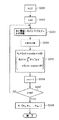
次に、原音場の臨場感に近い再生音を得るための付加情報、即ち反射音パターンの生成に関し、所定の周波数帯域に分割したケースについて図4〜図7を参照して説明する。尚、図4は音場の残響特性の補正について示す図であり、図5は付加する反射音パターンの生成の流れを示すフローチャートであり、図6は帯域別残響特性の計算の流れを示すフローチャートであり、図7は図5に示す反射音パターン生成における生成サブルーチンの流れを示すフローチャートである。
【0048】
図4に示すように、狭い部屋での再生音場残響特性は原音場残響特性に比べて、短い時間で残響は減衰する。この減衰を原音場での残響特性に近づけるため、直接音が到達した時刻t0から所定の時刻tcが経過した時刻teに、最初の反射音パターンを付加し、順次、周波数帯域別の反射音パターンを付加していく。反射音パターンのレベルは再生音場残響特性と原音場残響特性との差が所定の値より小さくなるように決定していく。この反射音パターンを再生する音源に付加することで原音場と同様の臨場感を得ることができる。
【0049】
次に、反射音パターンの生成の流れについて説明する。図5に示すように、まず、原音場でのインパルス応答h0を測定しておく。これは図1に示したシステムにより、例えば音楽ホール等の希望する臨場感の得られる音場で測定する(ステップ101)。次にその音場での周波数の帯域別残響特性を計算する(ステップ102)。この計算については図6を参照し、後段で説明する。これにより求められた帯域別(M個)の伝達関数R0は記録しておき、ステップ108の反射音パターンの生成に供される(ステップ103)。以上で目的とする原音場の残響特性のデータが得られたことになる。
【0050】
次に、再生音場でのインパルス応答h1を測定する(ステップ104)。これも図1に示したシステムにより再生する音場で測定する。帯域数は原音場と同様にMに分割したとして、最初の帯域についての反射音パターンを求めるためのイニシャライズを行う(ステップ105)。ここで分割する帯域は、例えば中心周波数を63、125、250、500、1k、2k、4k、8k、16kHzの9つの帯域に分割する。
【0051】
次に、帯域i番目のバンドパスフィルタの係数をBとし(ステップ106)、再生音場のインパルス応答とバンドパスフィルタの畳み込み演算を行う(ステップ107)。次に、先に求めた原音場のインパルス応答h0とから反射音パターンCを求める(ステップ108)。この反射音パターンの算出について後段で図7を参照し、後段で説明する。
【0052】
その後、次の帯域に設定し(ステップ109)、全ての帯域について反射音パターンの算出を行ったか否かを判別し(ステップ110)、まだ、算出すべき帯域があればステップ106に戻って、次の帯域についての反射音パターンを算出する。一方、全ての帯域について反射音パターンが得られていれば(ステップ111)、終了する。このようにして得られた反射音パターンを再生時に原音に付加することで、目的とする音場、即ち原音場の臨場感で、例えば音楽を聴くことが可能となる。
【0053】
次に、帯域別残響特性の計算について図6を参照して説明する。予め再生音場のインパルス応答を求めておく(ステップ201)。
【0054】
まず、周波数帯域はM個に分割されているとして、計算を最初の帯域に設定する(ステップ202)。次に、バンドパスフィルタの係数をBとし(ステップ203)、原音場のインパルス応答とバンドパスフィルタの畳み込み演算を行う(ステップ204)。次にシュレーダーの残響積分式を用いて残響減衰特性を計算する(ステップ205)。
【0055】
その後、次の帯域に設定し(ステップ206)、全ての帯域について残響減衰特性の算出を行ったか否かを判別し(ステップ207)、まだ、算出すべき帯域があればステップ203に戻って、次の帯域についての残響減衰特性を算出する。一方、全ての帯域について残響減衰特性が得られていれば(ステップ208)、終了する。ここでステップ208はステップ103に該当する。
【0056】
次に、反射音パターンの計算について図7を参照して説明する。まず、反射音パターンの初期状態を設定する(ステップ301)。次に、再生音場の残響特性を計算し(ステップ302)、原音場と再生音場の残響特性の差を演算する(ステップ303)。ここで原音場と再生音場の全帯域における残響特性の差を合計したものをErsとする(ステップ304)。このErsが設定された基準となる差異thより小さいか否かを判別し(ステップ305)、小さければ反射音パターンの生成を終了する。
【0057】
小さくなければ、エラー量の最大値をとる時間teを算出し(ステップ306)、時間teから再生音場のインパルス応答とバンドパスフィルタの畳み込み演算結果が最大となる時間を引いて時刻tcとし(ステップ307)、この時刻tcに反射音パターンCiを設定する(ステップ308)。更に反射音パターンCiに乱数を加え(ステップ309)、シュレーダーの残響積分式によって、帯域iの減衰特性を計算する(ステップ310)。
【0058】
次に、原音場と再生音場の周波数帯域iにおける減衰特性の差を求める(ステップ311)。これら差異を順次合計し(ステップ312)、その値がステップ304で求められたエラーよりも小さいか否かを判別する(ステップ313)。小さくなければステップ308に戻り、ステップ309で新しく発生された乱数を用いて、以下の演算を同様に行う。小さければエラー最小値と反射音パターンCiを設定し、ステップ305に戻って、エラー最小値が設定された値よりか小さいか否かを再度判別する。小さければ反射音パターンの算出を終了し、図5のフローチャートに従って、各周波数帯域の反射音パターンが決定され、再生音に重畳されることになる。
【0059】
以上説明したようにして、原音場と同様の臨場感を得ることができる音響を再生音場で得ることができるものである。尚、反射音パターンの生成方法は上述したことに限るものではない。原音場と再生音場の残響特性の差から、再生音に付加されるべき反射音パターンが得られる方法であれば如何なる方法も利用可能である。
【0060】
(音場制御方法に係わる第一の実施形態)
本発明の音場制御方法の第一実施形態について図8を参照して説明する。本実施形態の音場制御方法の工程は、原音場残響特性測定工程11、再生音場残響特性測定工程12、残響差異検出工程13、付加情報算出工程14、情報付加工程15を備える。
【0061】
原音場残響特性測定工程11は、原音場の残響特性を測定する工程であって、図1を参照して説明したように、スピーカに測定のための信号、例えばインパルス信号を入力して、音波として出力させ、その音波をスピーカの前方の所定の位置に配置されたマイクロホンによって収音し、収音した信号をアナライザーによって分析する工程である。マイクロホンは受聴者が受聴する際の頭部に該当する位置に設定される。原音場としては録音スタジオや音楽ホール等が想定できる。また、受聴者の好みの音場に設定することも可能である。
【0062】
インパルス信号は原理的には全ての周波数成分を含むものであって、スピーカとマイクロホンの特性を含め、音波の伝達経路の伝達関数が一度に測定可能である。音波の伝達経路としてはスピーカからマイクロホンへの直接音と音場の壁、天井、床、家具等に反射されて伝わる反射音があり、これらが音場固有の残響特性を構成する。測定された残響特性は記録装置に記録され、再生音場の残響特性と比較され、再生音への付加情報、即ち反射音パターンの算出に供される。また、インパルス信号に替えてM系列雑音やタイムストレッチドパルス等を用いることも可能である。
【0063】
再生音場残響特性測定工程12は、原音場残響特性測定工程11と同様の方法で再生音場の残響特性を測定する。再生音場とは例えば受聴者の自宅の一室や自動車の座席空間である。一般的に再生音場は原音場より狭い空間であり、狭い空間では残響特性は急速に減衰する。得られた残響特性は原音場の残響特性と比較され、原音場の残響特性と近似するように反射音パターンの算出に供される。
【0064】
残響差異検出工程13は、上述したようにして測定された原音場と再生音場の残響特性の差異を検出する。この差異が原音場と再生音場での臨場感等の差となって受聴者は感じることになる。
【0065】
付加情報算出工程14は、残響差異検出工程13で得られた原音場と再生音場の残響特性の差異に基づき、再生音場の再生音源16に付加して、原音場と同様の臨場感を得ることができるような付加情報、即ち反射音パターンを求める工程である。
【0066】
情報付加工程15は、付加情報算出工程14で求められた反射音パターンを音源16に加え、出力する工程である。出力信号は増幅器を通してスピーカに入力され、音響信号として発せられ、またはディスク等の記録媒体に記録される。ディスク等に記録し再生する場合は、再生するに際しては通常の音響再生装置が使用可能であり、原音場と同様の臨場感を得ることができる。
【0067】
尚、ステレオ等の複数のスピーカを用いる音響システムでは、スピーカごとに残響特性を測定し、反射音パターンを求めることが必要である。
【0068】
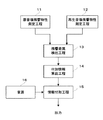
(音場制御方法に係わる第二の実施形態)
本発明の音場制御方法の第二実施形態について図9を参照して説明する。本実施形態の音場制御方法は、周波数帯域分割工程21、原音場残響特性測定工程22、再生音場残響特性測定工程23、残響差異検出工程24、付加情報算出工程25、情報付加工程26、合成工程28を備える。
【0069】
周波数帯域分割工程21は、音を所定の周波数帯域(f1〜f2、f2〜f3、・・・)に分割する工程である。残響特性は周波数帯域によって異なり、周波数の高い方は周波数の低い方に比べて残響特性は急速に減衰する。従って、所定の周波数帯域に分割し、各々の周波数帯域ごとに反射音パターンを生成して、音源27に加える。分割は、例えば中心周波数を63、125、250、500、1k、2k、4k、8k、16kHzの9つに分割する等が考えられる。
【0070】
原音場残響特性測定工程22、再生音場残響特性測定工程23、残響差異検出工程24、付加情報算出工程25、情報付加工程26は分割した周波数帯域ごとに作用することおいてのみ第一実施形態とは異なるものであり、その他の機能、作用は同一である。
【0071】
合成工程28は、反射音パターンが音源27に付加された周波数帯域ごとの信号を合成して出力する工程であり、反射音パターンが付加された再生音を復元し、出力する。出力信号は増幅器を通してスピーカに入力され、音響信号として発せられ、またはディスク等の記録媒体に記録されることも第一実施形態と同様である。
【0072】
(音場制御システムに係わる第一の実施形態)
本発明の音場制御システムの第一実施形態について図10を参照して説明する。本実施形態の構成は、スピーカ2、マイクロホン3、テスト信号発生器4、アナライザー7、記録装置8等を備えた残響特性測定手段31と、残響差異検出手段32と、付加情報算出手段33と、情報付加手段34を備える。
【0073】
残響特性測定手段31は、原音場及び再生音場の残響特性を測定する手段であって、図1を参照して説明したように、スピーカ2と、スピーカ2に入力する測定用信号、例えばインパルス信号を発生するテスト信号発生器4と、スピーカ2から発せられた音波を収音するマイクロホン3と、マイクロホン3で収音した音波からスピーカ2とマイクロホン3間のインパルス応答を分析し残響特性を求めるアナライザー7と、残響特性のデータを記録する記録装置8等を備えている。スピーカ2に入力する信号レベルやマイクロホン3で収音した信号のレベルを調整する増幅器等を更に備えていても良い。
【0074】
テスト信号発生器4からのインパルス信号でスピーカ2を駆動し、音波として出力させ、その音波をスピーカ2の前方の所定の位置に配置されたマイクロホン3によって収音し、収音した信号をアナライザー7によって残響特性を求める。マイクロホン3は受聴者が受聴する際の頭部に該当する位置に設定される。
【0075】
残響差異検出手段32は、残響特性測定手段31によって測定された原音場と再生音場の残響特性からその差異を検出する手段である。
【0076】
付加情報算出手段33は、残響差異検出手段32で得られた原音場と再生音場の残響特性の差異に基づき、再生音場の再生音源35に付加して、原音場と同様の臨場感を得ることができるような付加情報、即ち反射音パターンを求める手段である。
【0077】
情報付加手段34は、付加情報算出手段33で求められた反射音パターンを音源35に加え、出力する手段である。出力信号は増幅器を通してスピーカに入力され、音響信号として発せられ、またはディスク等の記録媒体に記録される。以上説明したシステム構成で再生音場における音響再生が、原音場での環境に近い状態で行うことが可能となる。
【0078】
尚、インパルス信号に替えてM系列雑音やタイムストレッチドパルス等を用いることも可能であることは上述したことと同様である。
【0079】
(音場制御システムに係わる第二の実施形態)
次に、本発明の音場制御システムの第二実施形態について図11を参照して説明する。本実施形態の構成は、周波数帯域分割手段41、残響特性測定手段42、残響差異検出手段43、付加情報算出手段44、情報付加手段46、合成手段47を備える。
【0080】
周波数帯域分割手段41は、音を所定の周波数帯域(f1〜f2、f2〜f3、・・・)に分割する手段である。残響特性は周波数帯域によって異なり、周波数の高い方は周波数の低い方に比べて残響特性は急速に減衰する。従って、周波数帯域ごとに反射音パターンを生成して、音源45に加えるために所定の周波数帯域に分割する。分割は上述したことと同様に、例えば中心周波数を63、125、250、500、1k、2k、4k、8k、16kHzの9つに分割する等が考えられる。
【0081】
残響特性測定手段42、残響差異検出手段43、付加情報算出手段44、情報付加手段47は分割した周波数帯域ごとに作用することおいてのみ第一実施形態とは異なるものであり、その他の機能、作用は同一である。
【0082】
合成手段47は、反射音パターンが音源45に付加された周波数帯域毎の信号を合成して出力する工程であり、反射音パターンが付加された再生音を復元する手段である。出力信号は増幅器を通してスピーカに入力され、音響信号として発せられ、またはディスク等の記録媒体に記録されることも第一実施形態と同様である。
【0083】
(音場制御システムに係わる第一の変形例)
次に、本発明の音場制御システムの第一変形例について図12を参照して説明する。本変形例は音源35からの信号を、分割した周波数帯域に相当する周波数帯域分割手段51、即ちバンドパスフィルタに入力し、通過した周波数の信号に対して、情報付加手段52により付加情報、即ち反射音パターンを付加し、その後、各々の周波数帯域の補正された音響信号を合成手段53で合成して、出力するシステム構成である。情報付加手段52により付加される反射音パターンは、それぞれの周波数帯域について、予め図4〜図7を参照して説明した手順で求めておく必要がある。原音場と再生音場がいつも決まっているような場合は、一度反射音パターンを求めておけば良く、システム構成も簡単である。
【0084】
尚、周波数帯域分割手段51と情報付加手段52は入力信号に対して前後を入れ替えることが可能である。
【0085】
(音場制御システムに係わる第二の変形例)
次に、本発明の音場制御システムの第二変形例について図13を参照して説明する。本変形例は第一変形例で示した情報付加手段52の後段にそれぞれ利得調整手段54を設けたものである。周波数帯域のそれぞれの音響信号に反射音パターンが付加された後、その信号レベルを周波数帯域ごとに調整が可能となり、全周波数帯域にわたって周波数特性を調整することが容易である。また、第一の変形例と同様に周波数帯域分割手段51と情報付加手段52は入力信号に対して前後を入れ替えることが可能である。
【0086】
(音場制御システムに係わる第三の変形例)
次に本発明の音場制御システムの第三変形例について図14を参照して説明する。本変形例は第二変形例で示した周波数帯域分割手段51、情報付加手段52、利得調整手段54を、フィルタ55で置き換えたものである。ここでフィルタ55は周波数帯域分割手段51から利得調整手段54までの伝達関数に略一致させて形成されているものである。システム構成が極めて簡単になる。
【0087】
更に、信号の入出力間の伝達関数を略一致させた1つのフィルタ56でシステムを構成することも可能である。
【0088】
本発明は、上述した実施形態に限られるものではなく、請求の範囲及び明細書全体から読み取れる発明の要旨或いは思想に反しない範囲で適宜変更可能であり、そのような変更を伴う音場制御方法及び音場制御システムもまた本発明の技術思想に含まれるものである。
【0089】
【発明の効果】
以上、説明したように本発明によれば、音響を再生する環境、即ち再生音場固有の残響特性を制御対象としているため、トランスオーラルシステム等の受聴位置でのピンポイント制御とは異なり、受聴位置がずれていても広い部屋と同等の臨場感のある再生音を得ることが可能となる。従って、自動車のような狭い室内においても、広い部屋で受聴しているのと同様な臨場感で聞くことができ、極めて効果的なシステムである。
【0090】
また、分割した周波数帯域ごとに残響特性を制御する形態では、各々の周波数帯域において固有の残響特性が制御されるため、より効果的に原音場と同様な臨場感を得ることが可能である。
【0091】
更に、従来のものでは必要であった逆フィルタに替わって、安定した近似フィルタを用いることが可能であり、比較的小規模のシステムで構成することができる。
【図面の簡単な説明】
【図1】本発明の音場制御方法及び音場制御システムにおける音場の残響特性を測定する測定系を示す図である。
【図2】残響特性を示す図であって、同図(a)は広い音場における残響特性の一例であり、同図(b)は狭い音場における残響特性の一例である。
【図3】残響特性を示す図であって、同図(a)は低い周波数の残響特性の一例であり、同図(b)は高い周波数の残響特性の一例である。
【図4】再生音場の残響特性の補正について示す図である。
【図5】付加する反射音パターンの生成の流れを示すフローチャートである。
【図6】周波数帯域ごとの残響特性の計算の流れを示すフローチャートである。
【図7】図5に示す反射音パターンの生成における生成サブルーチンの流れを示すフローチャートである。
【図8】本発明の音場制御方法における第一の実施形態について示す図である。
【図9】本発明の音場制御方法における第二の実施形態について示す図である。
【図10】本発明の音場制御システムにおける第一の実施形態について示す図である。
【図11】本発明の音場制御システムにおける第二の実施形態について示す図である。
【図12】本発明の音場制御システムにおける第一の変形例について示す図である。
【図13】本発明の音場制御システムにおける第二の変形例について示す図である。
【図14】本発明の音場制御システムにおける第三の変形例について示す図である。
【符号の説明】
1・・・音場
2・・・スピーカ
3・・・マイクロホン
4・・・テスト信号発生器
5、6・・・増幅器
7・・・アナライザー
8・・・記録装置
11、22・・・原音場残響特性測定工程
12、23・・・再生音場残響特性測定工程
13、24・・・残響差異検出工程
14、25・・・付加情報算出工程
15、26・・・情報付加工程
16、27、34、45・・・音源
21・・・周波数帯域分割工程
28・・・合成工程
31、42・・・残響特性測定手段
32、43・・・残響差異検出手段
33、44・・・付加情報算出手段
35、46、52・・・情報付加手段
41、51・・・周波数帯域分割手段
47、53・・・合成手段
54・・・利得調整手段
55、56・・・フィルタ[0001]
BACKGROUND OF THE INVENTION
The present invention belongs to the technical field of a sound field control method and a sound field control system for obtaining reproduced sound with a rich sense of presence by adding predetermined reverberation to the reproduced sound in sound reproduction in the reproduced sound field.
[0002]
[Prior art]
2. Description of the Related Art Conventionally, methods and systems for obtaining realistic sounds have been proposed when playing and listening to music. One of them is called a trans-oral system. This transoral system is the target sound space, and the target sound is heard by listening to the sound recorded at both ears of the dummy head placed at the position corresponding to the listener's position in the playback sound field. I try to get a sense of realism similar to what I hear in space.
[0003]
This is to match the sound pressures PL and PR at the entrances of the right and left ears of the dummy head when recording with the sound pressures SL and SR at the entrances of the ear canals of the left and right ears of the listener in the reproduction sound field Thus, the same acoustic information as the recorded sound field is given to the listener. In order to realize such a reproduction state, a reproduction equivalent filter called a crosstalk cancellation filter is provided to control the reproduction sound field.
[0004]
Similarly, there is a signal processing device called a reverberation adding device as a method for obtaining sound with a rich sense of presence. In general, there is a finite-length initial reflected sound generation unit in the front stage of the system, and the output signal is added to the reproduced sound source in the subsequent reverberation generation unit. The reverberation generation unit generally uses a form in which IIR (Infinite Impulse Response) type filters such as comb filters are arranged in parallel. In addition to these, a type in which an impulse response of a real sound field is convoluted with a reproduction sound source has been proposed.
[0005]
[Problems to be solved by the invention]
However, the conventional trans-oral system aims to strictly control the localization, reverberation, sound quality, etc. of the original sound field, so the optimal filter solution that cancels the characteristics of the reproduced sound field is not always stable. In addition, when there is a large difference between the characteristics of the original sound field and the reproduced sound field, the sound quality may be uncomfortable. In addition, by strictly determining the characteristics at the left and right binaural positions, you can get a sense of realism in the original sound field when listening at the optimal position, but if you listen at a position slightly off the point, what is the original sound field? There was a completely different sense of reality, and the narrowness of the control area was a problem.
[0006]
Further, in the conventional reverberation adding apparatus, acoustic additional information, that is, phase, amplitude, reverberation characteristics, and the like are determined and provided based on the designer's know-how without considering the characteristics of the reproduced sound field. For this reason, the additional information does not always match each sound field, and a long filter is required if the sound field data of the sound field is directly folded into the sound source. It was a composition.
[0007]
Therefore, the present invention has been made in view of the above problems, and adds sound information corresponding to the characteristics unique to each reproduction sound field, and the reproduced sound having the same realistic feeling as the original sound field regardless of the listening position. It is an object to provide a method and a system for obtaining information.
[0008]
[Means for Solving the Problems]
In order to solve the above problems, the sound field control method of the present invention measures a reverberation characteristic of a listening sound field to be heard, and a reverberation characteristic of a reference sound field as a reference.FromReverberation characteristics of the listening fieldPulledThe step of detecting the difference and the difference between the detected reverberation characteristicsAt the time when is the maximumAnd a step of calculating a reflected sound pattern for approximating the reverberation characteristic of the reference sound field to be added to a sound source for listening in the listening sound field, and a step of adding the calculated reflected sound pattern to the sound source. .
[0009]
According to the sound field control method of the present invention, when listening to sound, for example, even in a narrow listening space, it is a control method that makes it possible to obtain the same sense of presence as in a wide listening space.Standard to be used as standardThe sound field is, for example, a recording studio or a music hall,ListeningThe sound field corresponds to a listener's room, a car, or the like. The reverberation characteristics of the listening space greatly affect the sense of presence, but this reverberation characteristic attenuates more quickly in a narrow space than in a wide space, making it uncomfortable when listening to sound recorded in a wide space in a narrow space. Give.
[0010]
Therefore, in the present invention, the reverberation characteristic in the reference sound field and the reverberation characteristic in the listening sound field are measured, the difference between the two reverberation characteristics is detected, and added to the sound source reproduced in the listening sound field based on the difference.Reflected sound pattern to approximate the reverberation characteristics of the reference sound fieldIs added to the original sound during playback, so that a sense of presence similar to that heard in the reference sound field can be obtained.
[0011]
The sound waves that reach the listener are reflected directly from the speaker and reflected from the walls, ceiling, floor, furniture, etc. of the room and sent from the direct sound, and the reverberation characteristics are characteristics related to this reflected sound. It is. The reverberation is maintained longer in the larger room than in the smaller room. ThereforeStandardReverberation characteristics in the sound fieldListeningFrom the reverberation characteristics in the sound field,StandardThe reflected sound pattern is obtained so as to approach the reverberation characteristics in the sound field, and is added to the original sound during reproduction. Depending on the purpose,StandardThe sound field may be set in various states, and the listener can listen in a sound field that approximates the set environment.
[0012]
In order to solve the above problems, the sound field control method of the present invention measures a step of dividing a sound source to be listened to a predetermined frequency band and a reverberation characteristic of the listened sound field to be listened for each of the divided frequency bands. Process and reverberation characteristics of reference sound fieldFromReverberation characteristics of the listening fieldPulledThe difference is detected for each of the divided frequency bands, and the difference between the detected reverberation characteristicsAt the time when is the maximumA step of calculating, for each of the divided frequency bands, a reflected sound pattern for approximating the reverberation characteristics of the reference sound field to be added to a sound source for listening in the listening sound field; and for each of the calculated frequency bands Adding the reflected sound pattern to the sound source and synthesizing the sound source to which the reflected sound pattern for each frequency band is added.
[0013]
According to the sound field control method of the present invention,StandardReverberation characteristics in the sound fieldListeningFrom the reverberation characteristics in the sound field, as described aboveStandardWhen determining the reflected sound pattern to approximate the reverberation characteristics in the sound field, divide the sound source into a predetermined frequency band, determine the most effective reflected sound pattern in each frequency band, add it to the sound source for each frequency band, Further, it is a control method in which all are combined and output.
[0014]
As for the reverberation characteristic, a component having a high frequency attenuates more rapidly than a component having a low frequency. Therefore, a more effective presence can be obtained by obtaining an optimum reflected sound pattern for each frequency band and adding it to the sound source.
[0015]
In one aspect of the sound field control method of the present invention, it is added to the sound source.Reflected sound patternIs,It is assumed that it is reflected sound information.
[0016]
According to this aspect,StandardReverberation characteristics in the sound fieldListeningFrom the reverberation characteristics in the sound field, as described aboveListeningReverberation characteristics in the sound fieldStandardThe reflected sound pattern is obtained so as to approach the reverberation characteristics in the sound field.
[0017]
In another aspect of the sound field control method of the present invention, the reverberation characteristics are measured by driving a speaker with a predetermined signal, collecting sound waves emitted from the speaker with a microphone placed at a predetermined position, and This is performed by analyzing an impulse response between the speaker and the microphone from a predetermined signal and acoustic information collected by the microphone.
[0018]
According to this aspect, the reverberation characteristics are measured by inputting a predetermined signal to the speaker, generating a sound wave from the speaker, and collecting the sound wave by the microphone. It is obtained by analyzing the impulse response between the speaker and the microphone from the input predetermined signal and the signal picked up by the microphone. The microphone is placed at a position corresponding to the listener's head. The measurement result is recorded in the recording means and used as data for obtaining the reflected sound pattern. As the input signal, for example, an impulse signal, M-sequence noise, time stretched pulse, or the like is used. Further, a reverberation characteristic may be obtained in each frequency band using a band-limited burst signal or the like.
[0019]
In another aspect of the sound field control method of the present invention, the reverberation characteristics are measured and added to the sound source.Reflected sound patternCalculation of multiple speakersEach ofTo be done.
[0020]
According to this aspect, for example, in a stereo system, when reproducing using a plurality of speakers, the reverberation characteristics in the reference sound field and the listening sound field are individually measured for each of the speakers arranged in a predetermined place. To do. These reverberation characteristics add to the original sound for each speaker.Reflected sound patternAnd the additional information, that is, the reflected sound pattern is added and reproduced in the listening sound field, so that it is possible to obtain a sense of presence similar to the reference sound field even in stereo reproduction.
[0021]
In order to solve the above problems, the sound field control system of the present invention measures a reverberation characteristic of a listening sound field to be heard, and a reverberation characteristic of a reference sound field as a reference.FromReverberation characteristics of the listening fieldPulledThe means for detecting the difference and the difference between the detected reverberation characteristicsAt the time when is the maximumAnd means for calculating a reflected sound pattern for approximating the reverberation characteristic of the reference sound field to be added to the sound source for listening in the listening sound field, and means for adding the calculated reflected sound pattern to the sound source. .
[0022]
According to the sound field control system of the present invention, when listening to sound, for example, even in a narrow listening space, control is performed so that the same realistic sensation as in a wide listening space can be obtained.
[0023]
StandardA means of measuring the reverberation characteristics of the sound field;ListeningThe means for measuring the reverberation characteristics of the sound field measures reverberation characteristics in each sound field, and the same configuration is used. When using a different configuration, it is necessary to correct the measurement standard between the means.
[0024]
The means for detecting the difference in the reverberation characteristic detects the difference from the measurement result of the reverberation characteristic in the reference sound field and the reverberation characteristic in the listening sound field. Add to sound sourceReflected sound pattern to approximate the reverberation characteristics of the reference sound fieldMeans for calculating information to be added to the sound source reproduced in the listening sound field, that is, the reflected sound pattern, from the difference between the two reverberation characteristics. Also,Reflected sound patternIs added to the original sound when the original sound is reproduced in the listening field.Calculated reflected sound patternIs added. By these means, a sense of reality similar to that heard in the reference sound field can be obtained in the listening sound field.
[0025]
In order to solve the above problems, the sound field control system of the present invention divides a sound source for listening into a predetermined frequency band, and measures a reverberation characteristic of the listening sound field to be listened for each of the divided frequency bands. And reverberation characteristics of the reference sound fieldFromReverberation characteristics of the listening fieldPulledMeans for detecting a difference for each of the divided frequency bands, and a difference between the detected reverberation characteristicsAt the time when is the maximumA means for calculating, for each of the divided frequency bands, a reflected sound pattern for approximating the reverberation characteristics of the reference sound field to be added to a sound source for listening in the listening sound field; and for each of the calculated frequency bands Means for adding the reflected sound pattern to the sound source, and means for synthesizing the sound source to which the reflected sound pattern for each frequency band is added.
[0026]
According to the sound field control system of the present invention,StandardReverberation characteristics in the sound fieldListeningFrom the reverberation characteristics in the sound field, as described aboveStandardWhen finding the reflected sound pattern to approximate the reverberation characteristics in the sound field, divide the sound source into a predetermined frequency band, find the most effective reflected sound pattern in each frequency band, add it to the sound source for each frequency band, Furthermore, it is a system configured to synthesize and output all.
[0027]
The means for dividing the frequency band is added to the sound source when playing in the listening sound field from the reverberation characteristic in the reference sound field and the reverberation characteristic in the listening sound field.Reflected sound pattern to approximate the reverberation characteristics of the reference sound fieldIs obtained by dividing the frequency band by a predetermined bandwidth.
[0028]
Also,StandardA means of measuring the reverberation characteristics of the sound field;ListeningThe means for measuring the reverberation characteristics of the sound field measures reverberation characteristics for each frequency band in each sound field, and the same configuration is used. When different configurations are used, it is necessary to correct the measurement standard between the means.
[0029]
The means for detecting the difference between the reverberation characteristics detects the difference from the measurement result of the reverberation characteristics for each frequency band in the reference sound field and the listening sound field. Add to sound sourceReflected sound pattern to approximate the reverberation characteristics of the reference sound fieldMeans for calculating the information to be added to the sound source reproduced in the listening sound field, that is, the reflected sound pattern for each frequency band from the difference between the two reverberation characteristics. Also,Reflected sound patternIs added to the original sound when the original sound is reproduced in the listening field.Calculated reflected sound patternIs added for each frequency band. Furthermore, the means for synthesizing the sound source synthesizes and outputs the sound source to which the reflected sound pattern is added for each frequency band.
[0030]
In one aspect of the sound field control system of the present invention, there is provided means for adjusting a gain for each of the divided frequency bands.
[0031]
According to this aspect, since the level can be adjusted for each divided frequency band, it is possible to easily adjust the frequency characteristics.
[0032]
In another aspect of the sound field control system of the present invention, the means for dividing the frequency band and theCalculated reflected sound patternMeans for adding to the sound source, means for adjusting the gain, and means for synthesizing the sound sourceWhat is, Constructed using a filter with a transfer function that matches the transfer function between signal input and outputHas been
[0033]
According to this aspect, a desired reverberation characteristic can be added to the sound source by passing the sound source of the reproduction sound field through one filter having a transfer function that matches the transfer function between the signal input and output of the system configuration. , The system becomes simple. However, the transfer function needs to be obtained in advance according to the combination of the reference sound field and the listening sound field.
In another aspect of the sound field control system of the present invention, in each frequency band, the means for dividing the frequency band and theCalculated reflected sound patternAnd means for adjusting the gainWhat is, Constructed using a filter having a transfer function that matches the transfer function between the signal input and output through each of these meansHas been.
[0034]
According to this aspect, the means for dividing the frequency band, the means for adding information to the sound source, and the means for adjusting the gain are configured by a filter having a transfer function that matches the transfer function between the signal input and output. It is possible to adjust for each divided band.
[0035]
In another aspect of the sound field control system of the present invention, the means for measuring the reverberation characteristics includes a speaker, a means for generating a predetermined signal input to the speaker, and a microphone for collecting a sound wave emitted from the speaker. And means for analyzing an impulse response between the speaker and the microphone from the predetermined signal and acoustic information collected by the microphone.
[0036]
According to this aspect, a predetermined signal is input to the speaker, and a sound wave for reverberation characteristic measurement is emitted from the speaker. The microphone picks up the sound wave emitted from the speaker, and the means for analyzing the acoustic information analyzes the impulse response between the speaker and the microphone from the predetermined signal and the sound wave picked up by the microphone to obtain the reverberation characteristic. Furthermore, the reverberation characteristics obtained areListeningIt is recorded in the recording device as data for generating a reflected sound pattern to be added in the sound field.
[0037]
Such an operation and other advantages of the present invention will become apparent from the embodiments described below.
[0038]
DETAILED DESCRIPTION OF THE INVENTION
First, the reverberation characteristic measurement system and the characteristics of the reverberation characteristic depending on the sound field and frequency band will be described with reference to FIGS. Here, reverberation characteristics are reflected in the sound field wall, ceiling, floor, etc. in addition to the direct sound when the sound emitted from the speaker is transmitted to the listener in the sound field when listening to music, Regarding the characteristics of the transmitted sound, it affects the sense of presence of the listener. It has unique characteristics depending on the width of the sound field and the frequency band.
[0039]
1 is a diagram showing a measurement system for measuring the reverberation characteristics of the sound field in the sound field control method and sound field control system of the present invention, and FIG. 2 is a diagram showing the reverberation characteristics to be measured. FIG. 4A is an example of reverberation characteristics in a wide sound field, and FIG. 4B is an example of reverberation characteristics in a narrow sound field. FIG. 3 also shows reverberation characteristics. FIG. 3A is an example of reverberation characteristics at a low frequency, and FIG. 3B is an example of reverberation characteristics at a high frequency.
[0040]
As shown in FIG. 1, the reverberation characteristic measurement system drives, for example, a
[0041]
The reverberation characteristics are measured by this measurement system by adjusting the signal from the
[0042]
The sound wave signal picked up by the
[0043]
When a plurality of speakers are reproduced at a predetermined position as in a stereo device, the reverberation characteristics are individually measured for each speaker, and the reverberation characteristics corresponding to each speaker are corrected during reproduction. Note that a personal computer or the like equipped with a measurement program may be used instead of the
[0044]
Next, regarding the relationship between the width of the
[0045]
As for the reverberation characteristics depending on the frequency band, FIG. 3A is an example of the reverberation characteristics in the low frequency band, and FIG. 3B is an example of the reverberation characteristics in the high frequency band, and the time t0Is the total energy integrated value of the direct sound and the reflected sound that reaches the
[0046]
As described above, the reverberation characteristics differ depending on the conditions of the sound field for reproducing the sound and the frequency band, and the sense of reality due to the effect of the reflected sound differs depending on the environment where the listener listens to the music. Therefore, based on these factors, the present invention adds information related to the reflected sound to the reproduced sound in accordance with the reverberation characteristics of the reproduced sound field, so that a reproduced sound close to the realistic feeling of the original sound field can be obtained. It is something to try.
[0047]
Next, with respect to generation of additional information for obtaining a reproduced sound close to the realistic feeling of the original sound field, that is, the generation of a reflected sound pattern, a case where it is divided into predetermined frequency bands will be described with reference to FIGS. 4 is a diagram showing correction of the reverberation characteristics of the sound field, FIG. 5 is a flowchart showing a flow of generating a reflected sound pattern to be added, and FIG. 6 is a flowchart showing a calculation flow of the reverberation characteristics for each band. FIG. 7 is a flowchart showing the flow of the generation subroutine in the reflected sound pattern generation shown in FIG.
[0048]
As shown in FIG. 4, the reverberation characteristic of the reproduction sound field in a narrow room attenuates in a shorter time than the reverberation characteristic of the original sound field. In order to approximate this attenuation to the reverberation characteristics in the original sound field, the time t when the direct sound arrived0The first reflected sound pattern is added at a time te when a predetermined time tc has elapsed from the beginning, and the reflected sound pattern for each frequency band is sequentially added. The level of the reflected sound pattern is determined so that the difference between the reproduced sound field reverberation characteristic and the original sound field reverberation characteristic becomes smaller than a predetermined value. By adding this reflected sound pattern to the sound source to be reproduced, it is possible to obtain a sense of presence similar to the original sound field.
[0049]
Next, the flow of generating a reflected sound pattern will be described. As shown in FIG. 5, first, the impulse response h in the original sound field0Measure it. This is measured by the system shown in FIG. 1 in a sound field where a desired presence can be obtained, such as a music hall (step 101). Next, a reverberation characteristic of each frequency band in the sound field is calculated (step 102). This calculation will be described later with reference to FIG. The transfer function R for each band (M) determined in this way0Are recorded and used for the generation of the reflected sound pattern in step 108 (step 103). Thus, the target reverberation characteristic data of the original sound field is obtained.
[0050]
Next, impulse response h in the reproduction sound field1Is measured (step 104). This is also measured in the sound field reproduced by the system shown in FIG. Assuming that the number of bands is divided into M as in the original sound field, initialization is performed to obtain a reflected sound pattern for the first band (step 105). The band to be divided here is, for example, divided into nine bands of 63, 125, 250, 500, 1k, 2k, 4k, 8k, and 16 kHz.
[0051]
Next, the coefficient of the band-pass filter for band i is set to B (step 106), and the impulse response of the reproduction sound field and the band-pass filter are convolved (step 107). Next, the impulse response h of the original sound field obtained previously0The reflected sound pattern C is obtained from the above (step 108). The calculation of the reflected sound pattern will be described later with reference to FIG.
[0052]
Thereafter, the next band is set (step 109), it is determined whether or not the reflected sound pattern has been calculated for all bands (step 110), and if there is still a band to be calculated, the process returns to step 106, The reflected sound pattern for the next band is calculated. On the other hand, if the reflected sound pattern has been obtained for all the bands (step 111), the process ends. By adding the reflected sound pattern thus obtained to the original sound at the time of reproduction, it becomes possible to listen to, for example, music with the target sound field, that is, the presence of the original sound field.
[0053]
Next, calculation of reverberation characteristics for each band will be described with reference to FIG. The impulse response of the reproduction sound field is obtained in advance (step 201).
[0054]
First, assuming that the frequency band is divided into M, the calculation is set to the first band (step 202). Next, the bandpass filter coefficient is set to B (step 203), and the impulse response of the original sound field and the bandpass filter convolution operation are performed (step 204). Next, a reverberation attenuation characteristic is calculated using Schroder's reverberation integral formula (step 205).
[0055]
Thereafter, the next band is set (step 206), and it is determined whether or not the reverberation attenuation characteristics have been calculated for all bands (step 207). If there is still a band to be calculated, the process returns to step 203, The reverberation attenuation characteristic for the next band is calculated. On the other hand, if the reverberation attenuation characteristics have been obtained for all the bands (step 208), the process ends. Here,
[0056]
Next, calculation of the reflected sound pattern will be described with reference to FIG. First, the initial state of the reflected sound pattern is set (step 301). Next, the reverberation characteristic of the reproduction sound field is calculated (step 302), and the difference between the reverberation characteristics of the original sound field and the reproduction sound field is calculated (step 303). Here, the sum of the differences of the reverberation characteristics in the entire band of the original sound field and the reproduced sound field is defined as Ers (step 304). It is determined whether or not this Ers is smaller than the set reference difference th (step 305), and if it is smaller, the generation of the reflected sound pattern is terminated.
[0057]
If it is not smaller, a time te that takes the maximum value of the error amount is calculated (step 306), and a time tc is obtained by subtracting from the time te the time when the impulse response of the reproduction sound field and the convolution calculation result of the bandpass filter become maximum ( In step 307), the reflected sound pattern Ci is set at this time tc (step 308). Further, a random number is added to the reflected sound pattern Ci (step 309), and the attenuation characteristic of the band i is calculated by Schroeder reverberation integral formula (step 310).
[0058]
Next, a difference in attenuation characteristics in the frequency band i between the original sound field and the reproduced sound field is obtained (step 311). These differences are sequentially summed (step 312), and it is determined whether or not the value is smaller than the error obtained in step 304 (step 313). If it is not smaller, the process returns to step 308, and the following calculation is similarly performed using the random number newly generated in
[0059]
As described above, it is possible to obtain sound in the reproduced sound field that can provide the same realistic sensation as the original sound field. The method for generating the reflected sound pattern is not limited to the above. Any method can be used as long as a reflected sound pattern to be added to the reproduced sound can be obtained from the difference between the reverberation characteristics of the original sound field and the reproduced sound field.
[0060]
(First embodiment related to sound field control method)
A first embodiment of the sound field control method of the present invention will be described with reference to FIG. The process of the sound field control method of this embodiment includes an original sound field reverberation
[0061]
The original sound field reverberation
[0062]
The impulse signal includes all frequency components in principle, and the transfer function of the sound wave transmission path including the characteristics of the speaker and the microphone can be measured at a time. The sound wave transmission path includes a direct sound from the speaker to the microphone and a reflected sound that is reflected by the sound field wall, ceiling, floor, furniture, etc., and these constitute reverberation characteristics unique to the sound field. The measured reverberation characteristic is recorded in a recording device, compared with the reverberation characteristic of the reproduction sound field, and used for calculating additional information to the reproduction sound, that is, a reflected sound pattern. It is also possible to use M-sequence noise, time stretched pulse or the like instead of the impulse signal.
[0063]
The reproduction sound field reverberation
[0064]
The reverberation
[0065]
The additional information calculation step 14 adds the
[0066]
The
[0067]
In an acoustic system using a plurality of speakers such as stereo, it is necessary to measure reverberation characteristics for each speaker and obtain a reflected sound pattern.
[0068]
(Second embodiment related to sound field control method)
A second embodiment of the sound field control method of the present invention will be described with reference to FIG. The sound field control method of the present embodiment includes a frequency
[0069]
The frequency
[0070]
Original sound field reverberation
[0071]
The synthesizing
[0072]
(First embodiment related to sound field control system)
A first embodiment of the sound field control system of the present invention will be described with reference to FIG. The configuration of this embodiment includes a reverberation
[0073]
The reverberation characteristic measuring means 31 is a means for measuring the reverberation characteristics of the original sound field and the reproduced sound field. As described with reference to FIG. 1, the reverberation characteristic measuring means 31 is a measurement signal input to the
[0074]
The
[0075]
The reverberation difference detection means 32 is means for detecting the difference from the reverberation characteristics of the original sound field and the reproduction sound field measured by the reverberation characteristic measurement means 31.
[0076]
The additional information calculation means 33 adds the reverberation characteristics between the original sound field and the reproduction sound field obtained by the reverberation difference detection means 32 to the
[0077]
The
[0078]
As described above, M-sequence noise, time stretched pulse, or the like can be used instead of the impulse signal.
[0079]
(Second embodiment related to sound field control system)
Next, a second embodiment of the sound field control system of the present invention will be described with reference to FIG. The configuration of this embodiment includes a frequency
[0080]
The frequency band dividing means 41 is a means for dividing the sound into predetermined frequency bands (f1 to f2, f2 to f3,...). The reverberation characteristic varies depending on the frequency band, and the reverberation characteristic attenuates more rapidly at higher frequencies than at lower frequencies. Therefore, a reflected sound pattern is generated for each frequency band and is divided into a predetermined frequency band to be applied to the
[0081]
The reverberation characteristic measuring means 42, the reverberation
[0082]
The synthesizing
[0083]
(First modification related to sound field control system)
Next, a first modification of the sound field control system of the present invention will be described with reference to FIG. In this modification, a signal from the
[0084]
The frequency band dividing means 51 and the information adding means 52 can be interchanged with respect to the input signal.
[0085]
(Second modification related to the sound field control system)
Next, a second modification of the sound field control system of the present invention will be described with reference to FIG. In this modification, gain adjusting means 54 is provided in the subsequent stage of the information adding means 52 shown in the first modification. After the reflected sound pattern is added to each acoustic signal in the frequency band, the signal level can be adjusted for each frequency band, and it is easy to adjust the frequency characteristics over the entire frequency band. Similarly to the first modification, the frequency band dividing means 51 and the information adding means 52 can interchange the front and rear with respect to the input signal.
[0086]
(Third modification of the sound field control system)
Next, a third modification of the sound field control system of the present invention will be described with reference to FIG. In this modified example, the frequency
[0087]
Further, it is possible to configure the system with one
[0088]
The present invention is not limited to the above-described embodiment, and can be appropriately changed without departing from the spirit or idea of the invention that can be read from the claims and the entire specification, and a sound field control method with such a change. The sound field control system is also included in the technical idea of the present invention.
[0089]
【The invention's effect】
As described above, according to the present invention, the environment to reproduce sound, that is, the reverberation characteristic specific to the reproduction sound field is controlled, so that it is different from the pinpoint control at the listening position of the transoral system or the like. Even if the position is shifted, it is possible to obtain a reproduced sound with a sense of presence equivalent to that of a large room. Therefore, even in a small room such as an automobile, it can be heard with a sense of presence similar to that of listening in a large room, which is an extremely effective system.
[0090]
Further, in the form in which the reverberation characteristics are controlled for each divided frequency band, the reverberation characteristics unique to each frequency band are controlled, so that it is possible to more effectively obtain a sense of realism similar to the original sound field.
[0091]
Furthermore, a stable approximate filter can be used in place of the inverse filter that was necessary in the prior art, and a relatively small system can be configured.
[Brief description of the drawings]
FIG. 1 is a diagram showing a measurement system for measuring reverberation characteristics of a sound field in a sound field control method and a sound field control system of the present invention.
2A and 2B are diagrams illustrating reverberation characteristics, in which FIG. 2A is an example of reverberation characteristics in a wide sound field, and FIG. 2B is an example of reverberation characteristics in a narrow sound field.
3A and 3B are diagrams showing reverberation characteristics, in which FIG. 3A is an example of a low frequency reverberation characteristic, and FIG. 3B is an example of a high frequency reverberation characteristic;
FIG. 4 is a diagram illustrating correction of reverberation characteristics of a reproduction sound field.
FIG. 5 is a flowchart showing a flow of generating a reflected sound pattern to be added.
FIG. 6 is a flowchart showing a flow of calculation of reverberation characteristics for each frequency band.
7 is a flowchart showing a flow of a generation subroutine in generation of a reflected sound pattern shown in FIG.
FIG. 8 is a diagram showing a first embodiment in the sound field control method of the present invention.
FIG. 9 is a diagram showing a second embodiment in the sound field control method of the present invention.
FIG. 10 is a diagram showing a first embodiment in the sound field control system of the present invention.
FIG. 11 is a diagram showing a second embodiment in the sound field control system of the present invention.
FIG. 12 is a diagram showing a first modification of the sound field control system of the present invention.
FIG. 13 is a diagram showing a second modification of the sound field control system of the present invention.
FIG. 14 is a diagram showing a third modification of the sound field control system of the present invention.
[Explanation of symbols]
1 ... Sound field
2 ... Speaker
3 ... Microphone
4 ... Test signal generator
5, 6 ... Amplifier
7 ... Analyzer
8 ... Recording device
11, 22 ... Original field reverberation characteristics measurement process
12, 23 ... Reproduction sound field reverberation characteristic measurement process
13, 24 ... reverberation difference detection step
14, 25 ... Additional information calculation step
15, 26 ... Information adding process
16, 27, 34, 45 ... sound source
21 ... Frequency band dividing step
28 ... Synthesis process
31, 42 ... Reverberation characteristic measuring means
32, 43 ... reverberation difference detection means
33, 44 ... Additional information calculating means
35, 46, 52 ... Information adding means
41, 51 ... frequency band dividing means
47, 53... Synthesis means
54 ... Gain adjusting means
55, 56 ... Filter
Claims (11)
基準とする基準音場の残響特性から、前記受聴音場の残響特性を引いた差異を検出する工程と、
検出された前記残響特性の差異が最大となる時間に、前記受聴音場において受聴に供する音源に付加する前記基準音場の残響特性に近づけるための反射音パターンを算出する工程と、
前記算出された反射音パターンを前記音源に付加する工程とを備えること
を特徴とする音場制御方法。Measuring the reverberation characteristics of the listening field to be heard;
Detecting a difference obtained by subtracting the reverberation characteristic of the listening sound field from the reverberation characteristic of the reference sound field as a reference; and
Calculating a reflected sound pattern for approximating the reverberation characteristic of the reference sound field to be added to a sound source for listening in the listening sound field at a time when the difference between the detected reverberation characteristics is maximum ;
Adding the calculated reflected sound pattern to the sound source.
受聴する受聴音場の残響特性を、前記分割した周波数帯域ごとに測定する工程と、
基準とする基準音場の残響特性から、前記受聴音場の残響特性を引いた差異を、前記分割された周波数帯域ごとに検出する工程と、
検出された前記残響特性の差異が最大となる時間に、前記受聴音場において受聴に供する音源に付加する前記基準音場の残響特性に近づけるための反射音パターンを、前記分割された周波数帯域ごとに算出する工程と、
前記算出された前記周波数帯域ごとの反射音パターンを前記音源に付加する工程と、
前記周波数帯域ごとの反射音パターンが付加された前記音源を合成する工程とを備えること
を特徴とする音場制御方法。Dividing a sound source for listening into a predetermined frequency band;
Measuring the reverberation characteristics of the listening sound field to be listened for each of the divided frequency bands;
Detecting the difference obtained by subtracting the reverberation characteristic of the listening sound field from the reverberation characteristic of the reference sound field as a reference for each of the divided frequency bands;
A reflected sound pattern for approximating the reverberation characteristic of the reference sound field to be added to the sound source to be listened to in the listening sound field at the time when the difference in the detected reverberation characteristic is maximized for each of the divided frequency bands. A step of calculating
Adding a reflected sound pattern for each of the calculated frequency bands to the sound source;
Synthesizing the sound source to which the reflected sound pattern for each frequency band is added.
を特徴とする請求項1及び請求項2のいずれか一項に記載の音場制御方法。The sound field control method according to claim 1, wherein the reflected sound pattern added to the sound source is reflected sound information.
前記スピーカから発せられた音波を所定位置に置かれたマイクロホンで収音し、
前記所定の信号と前記マイクロホンで収音した音響情報とから、前記スピーカと前記マイクロホン間のインパルス応答を分析することにより行われること
を特徴とする請求項1から請求項3のいずれか一項に記載の音場制御方法。The reverberation characteristics are measured by driving a speaker with a predetermined signal,
The sound wave emitted from the speaker is collected by a microphone placed in a predetermined position,
The analysis is performed by analyzing an impulse response between the speaker and the microphone from the predetermined signal and acoustic information collected by the microphone. The described sound field control method.
を特徴とする請求項1から請求項4のいずれか一項に記載の音場制御方法。The measurement of the reverberation characteristic and the calculation of the reflected sound pattern added to the sound source are performed for each of a plurality of speakers. Sound field control method.
基準とする基準音場の残響特性から、前記受聴音場の残響特性を引いた差異を検出する手段と、
検出された前記残響特性の差異が最大となる時間に、前記受聴音場において受聴に供する音源に付加される反射音パターンを算出する手段と、
前記算出された反射音パターンを前記音源に付加する手段とを備えること
を特徴とする音場制御システム。Means for measuring the reverberation characteristics of the listening sound field to be heard;
Means for detecting a difference obtained by subtracting the reverberation characteristic of the listening sound field from the reverberation characteristic of the reference sound field as a reference;
Means for calculating a reflected sound pattern to be added to a sound source for listening in the listening sound field at a time when the difference in the detected reverberation characteristic is maximum ;
Means for adding the calculated reflected sound pattern to the sound source.
受聴する受聴音場の残響特性を、前記分割した周波数帯域ごとに測定する手段と、
基準とする基準音場の残響特性から、前記受聴音場の残響特性を引いた差異を、前記分割された周波数帯域ごとに検出する手段と、
検出された前記残響特性の差異が最大となる時間に、前記受聴音場において受聴に供する音源に付加される反射音パターンを、前記分割された周波数帯域ごとに算出する手段と、
前記算出された前記周波数帯域ごとの反射音パターンを前記音源に付加する手段と、
前記周波数帯域ごとの反射音パターンが付加された前記音源を合成する手段とを備えること
を特徴とする音場制御システム。Means for dividing a sound source for listening into a predetermined frequency band;
Means for measuring the reverberation characteristics of the listening sound field for each of the divided frequency bands;
Means for detecting, for each of the divided frequency bands, a difference obtained by subtracting the reverberation characteristic of the listening sound field from the reverberation characteristic of the reference sound field as a reference;
Means for calculating, for each of the divided frequency bands, a reflected sound pattern added to a sound source to be listened to in the listening sound field at a time when the difference between the detected reverberation characteristics is maximum ;
Means for adding the calculated reflected sound pattern for each frequency band to the sound source;
Means for synthesizing the sound source to which the reflected sound pattern for each frequency band is added.
を特徴とする請求項7に記載の音場制御システム。The sound field control system according to claim 7, further comprising means for adjusting a gain for each of the divided frequency bands.
を特徴とする請求項8に記載の音場制御システム。The means for dividing the frequency band, the means for adding the calculated reflected sound pattern to the sound source, the means for adjusting the gain, and the means for synthesizing the sound source include a transfer function that matches a transfer function between signal inputs and outputs The sound field control system according to claim 8, wherein the sound field control system is configured using a filter having the following.
を特徴とする請求項8に記載の音場制御システム。In each frequency band, the means for dividing the frequency band, the means for adding the calculated reflected sound pattern to the sound source, and the means for adjusting the gain are between the signal input and output through these means. The sound field control system according to claim 8, wherein the sound field control system is configured using a filter having a transfer function that matches the transfer function.
を備えることを特徴とする請求項6から請求項10のいずれか一項に記載の音場制御システム。The means for measuring the reverberation characteristics includes a speaker, a means for generating a predetermined signal to be input to the speaker, a microphone for collecting sound waves emitted from the speaker, and a sound collected by the predetermined signal and the microphone. The sound field control system according to any one of claims 6 to 10, further comprising means for analyzing an impulse response between the speaker and the microphone from information.
Priority Applications (3)
| Application Number | Priority Date | Filing Date | Title |
|---|---|---|---|
| JP2002053483A JP4059478B2 (en) | 2002-02-28 | 2002-02-28 | Sound field control method and sound field control system |
| EP02258805.7A EP1341399B1 (en) | 2002-02-28 | 2002-12-19 | Sound field control method and sound field control system |
| US10/322,662 US6909041B2 (en) | 2002-02-28 | 2002-12-19 | Sound field control method and sound field control system |
Applications Claiming Priority (1)
| Application Number | Priority Date | Filing Date | Title |
|---|---|---|---|
| JP2002053483A JP4059478B2 (en) | 2002-02-28 | 2002-02-28 | Sound field control method and sound field control system |
Publications (3)
| Publication Number | Publication Date |
|---|---|
| JP2003255955A JP2003255955A (en) | 2003-09-10 |
| JP2003255955A5 JP2003255955A5 (en) | 2005-03-17 |
| JP4059478B2 true JP4059478B2 (en) | 2008-03-12 |
Family
ID=27678554
Family Applications (1)
| Application Number | Title | Priority Date | Filing Date |
|---|---|---|---|
| JP2002053483A Expired - Fee Related JP4059478B2 (en) | 2002-02-28 | 2002-02-28 | Sound field control method and sound field control system |
Country Status (3)
| Country | Link |
|---|---|
| US (1) | US6909041B2 (en) |
| EP (1) | EP1341399B1 (en) |
| JP (1) | JP4059478B2 (en) |
Families Citing this family (46)
| Publication number | Priority date | Publication date | Assignee | Title |
|---|---|---|---|---|
| GB0301093D0 (en) * | 2003-01-17 | 2003-02-19 | 1 Ltd | Set-up method for array-type sound systems |
| JP2005252467A (en) * | 2004-03-02 | 2005-09-15 | Sony Corp | Sound reproduction method, sound reproducing device and recording medium |
| WO2006003957A1 (en) | 2004-06-30 | 2006-01-12 | Pioneer Corporation | Reverberation adjustment device, reverberation adjustment method, reverberation adjustment program, recording medium containing the program, and sound field correction system |
| US8023662B2 (en) | 2004-07-05 | 2011-09-20 | Pioneer Corporation | Reverberation adjusting apparatus, reverberation correcting method, and sound reproducing system |
| JP2006030443A (en) * | 2004-07-14 | 2006-02-02 | Sony Corp | Recording medium, recording device and method, data processor and method, data output system, and method |
| JP4222276B2 (en) * | 2004-08-27 | 2009-02-12 | ソニー株式会社 | Playback system |
| US8284947B2 (en) | 2004-12-01 | 2012-10-09 | Qnx Software Systems Limited | Reverberation estimation and suppression system |
| US20090220105A1 (en) * | 2005-05-01 | 2009-09-03 | Harry Bachmann | Method for compensating for changes in reproduced audio signals and a corresponding device |
| ATE459216T1 (en) * | 2005-06-28 | 2010-03-15 | Akg Acoustics Gmbh | METHOD FOR SIMULATING A SPACE IMPRESSION AND/OR SOUND IMPRESSION |
| JP2007280485A (en) | 2006-04-05 | 2007-10-25 | Sony Corp | Recording device, reproducing device, recording and reproducing device, recording method, reproducing method, recording and reproducing method, and recording medium |
| JP4834146B2 (en) * | 2007-03-09 | 2011-12-14 | パイオニア株式会社 | Sound field reproduction apparatus and sound field reproduction method |
| JP2009128559A (en) * | 2007-11-22 | 2009-06-11 | Casio Comput Co Ltd | Reverberation effect adding device |
| JP5151483B2 (en) * | 2008-01-07 | 2013-02-27 | ヤマハ株式会社 | Coefficient measuring device, effect applying device, and musical sound generating device |
| EP2416314A4 (en) * | 2009-04-01 | 2013-05-22 | Azat Fuatovich Zakirov | Method for reproducing an audio recording with the simulation of the acoustic characteristics of the recording conditions |
| JP5516060B2 (en) * | 2009-05-19 | 2014-06-11 | ヤマハ株式会社 | Sound field control device |
| GB2471089A (en) * | 2009-06-16 | 2010-12-22 | Focusrite Audio Engineering Ltd | Audio processing device using a library of virtual environment effects |
| JP5672748B2 (en) * | 2010-03-31 | 2015-02-18 | ヤマハ株式会社 | Sound field control device |
| JP5699844B2 (en) * | 2011-07-28 | 2015-04-15 | 富士通株式会社 | Reverberation suppression apparatus, reverberation suppression method, and reverberation suppression program |
| US9084058B2 (en) | 2011-12-29 | 2015-07-14 | Sonos, Inc. | Sound field calibration using listener localization |
| JP2013143744A (en) * | 2012-01-12 | 2013-07-22 | Denso Corp | Sound image presentation device |
| US9219460B2 (en) | 2014-03-17 | 2015-12-22 | Sonos, Inc. | Audio settings based on environment |
| US9106192B2 (en) | 2012-06-28 | 2015-08-11 | Sonos, Inc. | System and method for device playback calibration |
| US8822804B1 (en) * | 2013-02-09 | 2014-09-02 | Vladimir Vassilev | Digital aerophones and dynamic impulse response systems |
| US9264839B2 (en) | 2014-03-17 | 2016-02-16 | Sonos, Inc. | Playback device configuration based on proximity detection |
| US9952825B2 (en) | 2014-09-09 | 2018-04-24 | Sonos, Inc. | Audio processing algorithms |
| JP6056842B2 (en) * | 2014-12-26 | 2017-01-11 | ヤマハ株式会社 | Sound field control device |
| US10393571B2 (en) | 2015-07-06 | 2019-08-27 | Dolby Laboratories Licensing Corporation | Estimation of reverberant energy component from active audio source |
| EP3531714B1 (en) | 2015-09-17 | 2022-02-23 | Sonos Inc. | Facilitating calibration of an audio playback device |
| US9693165B2 (en) | 2015-09-17 | 2017-06-27 | Sonos, Inc. | Validation of audio calibration using multi-dimensional motion check |
| US9743207B1 (en) | 2016-01-18 | 2017-08-22 | Sonos, Inc. | Calibration using multiple recording devices |
| US10003899B2 (en) | 2016-01-25 | 2018-06-19 | Sonos, Inc. | Calibration with particular locations |
| US11106423B2 (en) * | 2016-01-25 | 2021-08-31 | Sonos, Inc. | Evaluating calibration of a playback device |
| US9860662B2 (en) | 2016-04-01 | 2018-01-02 | Sonos, Inc. | Updating playback device configuration information based on calibration data |
| US9864574B2 (en) | 2016-04-01 | 2018-01-09 | Sonos, Inc. | Playback device calibration based on representation spectral characteristics |
| US9763018B1 (en) | 2016-04-12 | 2017-09-12 | Sonos, Inc. | Calibration of audio playback devices |
| US9794710B1 (en) | 2016-07-15 | 2017-10-17 | Sonos, Inc. | Spatial audio correction |
| US10372406B2 (en) | 2016-07-22 | 2019-08-06 | Sonos, Inc. | Calibration interface |
| US10459684B2 (en) | 2016-08-05 | 2019-10-29 | Sonos, Inc. | Calibration of a playback device based on an estimated frequency response |
| KR102633727B1 (en) | 2017-10-17 | 2024-02-05 | 매직 립, 인코포레이티드 | Mixed Reality Spatial Audio |
| CN111713091A (en) | 2018-02-15 | 2020-09-25 | 奇跃公司 | Mixed reality virtual reverberation |
| US10299061B1 (en) | 2018-08-28 | 2019-05-21 | Sonos, Inc. | Playback device calibration |
| US11206484B2 (en) | 2018-08-28 | 2021-12-21 | Sonos, Inc. | Passive speaker authentication |
| US10734965B1 (en) | 2019-08-12 | 2020-08-04 | Sonos, Inc. | Audio calibration of a portable playback device |
| JP7446420B2 (en) | 2019-10-25 | 2024-03-08 | マジック リープ, インコーポレイテッド | Echo fingerprint estimation |
| WO2024029634A1 (en) * | 2022-08-03 | 2024-02-08 | マクセル株式会社 | Broadcast reception device, content protection method, processing method for adding reverberation sound, and control method for broadcast reception device |
| WO2024035873A1 (en) * | 2022-08-12 | 2024-02-15 | Ibiquity Digital Corporation | Ambiance expansion system for a vehicle |
Family Cites Families (11)
| Publication number | Priority date | Publication date | Assignee | Title |
|---|---|---|---|---|
| JPS5666919A (en) * | 1979-11-05 | 1981-06-05 | Nippon Columbia Co Ltd | Automatic corrector for sound field |
| JPS57188119A (en) * | 1981-11-07 | 1982-11-19 | Sony Corp | Acoustic character correcting device |
| JP2646210B2 (en) * | 1987-05-27 | 1997-08-27 | ヤマハ株式会社 | Electroacoustic reverberation support device |
| JP2892205B2 (en) * | 1991-11-28 | 1999-05-17 | 株式会社ケンウッド | Transmission frequency characteristic correction device |
| JP2737595B2 (en) * | 1993-03-26 | 1998-04-08 | ヤマハ株式会社 | Sound field control device |
| US5572443A (en) * | 1993-05-11 | 1996-11-05 | Yamaha Corporation | Acoustic characteristic correction device |
| JPH07334181A (en) * | 1994-06-08 | 1995-12-22 | Matsushita Electric Ind Co Ltd | Sound reverberation generating device |
| US6399868B1 (en) * | 2000-09-28 | 2002-06-04 | Roland Corporation | Sound effect generator and audio system |
| JP3823824B2 (en) * | 2001-12-27 | 2006-09-20 | ヤマハ株式会社 | Electronic musical sound generator and signal processing characteristic adjustment method |
| JP3843841B2 (en) * | 2002-01-10 | 2006-11-08 | ヤマハ株式会社 | Electronic musical instruments |
| JP3767493B2 (en) * | 2002-02-19 | 2006-04-19 | ヤマハ株式会社 | Acoustic correction filter design method, acoustic correction filter creation method, acoustic correction filter characteristic determination device, and acoustic signal output device |
-
2002
- 2002-02-28 JP JP2002053483A patent/JP4059478B2/en not_active Expired - Fee Related
- 2002-12-19 EP EP02258805.7A patent/EP1341399B1/en not_active Expired - Lifetime
- 2002-12-19 US US10/322,662 patent/US6909041B2/en not_active Expired - Fee Related
Also Published As
| Publication number | Publication date |
|---|---|
| EP1341399A3 (en) | 2004-09-29 |
| EP1341399A2 (en) | 2003-09-03 |
| EP1341399B1 (en) | 2014-06-18 |
| US20030159569A1 (en) | 2003-08-28 |
| JP2003255955A (en) | 2003-09-10 |
| US6909041B2 (en) | 2005-06-21 |
Similar Documents
| Publication | Publication Date | Title |
|---|---|---|
| JP4059478B2 (en) | Sound field control method and sound field control system | |
| US4823391A (en) | Sound reproduction system | |
| JP5637661B2 (en) | Method for recording and playing back sound sources with time-varying directional characteristics | |
| JP3584800B2 (en) | Sound field reproduction method and apparatus | |
| US20050195984A1 (en) | Sound reproducing method and apparatus | |
| JP2003255955A5 (en) | ||
| JPH02503721A (en) | electroacoustic system | |
| JP3578783B2 (en) | Sound image localization device for electronic musical instruments | |
| JP5611970B2 (en) | Converter and method for converting audio signals | |
| JP4222276B2 (en) | Playback system | |
| JP3594281B2 (en) | Stereo expansion device and sound field expansion device | |
| JP2006509439A (en) | Personalized surround sound headphone system | |
| JP2007333813A (en) | Electronic piano apparatus, sound field synthesizing method of electronic piano and sound field synthesizing program for electronic piano | |
| JP2004279525A (en) | Sound field control system and sound field control method | |
| US6925426B1 (en) | Process for high fidelity sound recording and reproduction of musical sound | |
| WO1997004620A1 (en) | Headphone device | |
| JP3521451B2 (en) | Sound image localization device | |
| JP2008282042A (en) | Reproduction device | |
| JP4845407B2 (en) | How to generate a reference filter | |
| JP4427915B2 (en) | Virtual sound image localization processor | |
| JP2991452B2 (en) | Sound signal reproduction device | |
| EP2079252A1 (en) | Sound image localization processing apparatus and others | |
| JPH07203597A (en) | Headphone reproducing device | |
| JPH03284800A (en) | Accoustic device | |
| Extra et al. | Artificial reverberation: Comparing algorithms by using monaural analysis tools |
Legal Events
| Date | Code | Title | Description |
|---|---|---|---|
| A521 | Written amendment |
Free format text: JAPANESE INTERMEDIATE CODE: A523 Effective date: 20040408 |
|
| A621 | Written request for application examination |
Free format text: JAPANESE INTERMEDIATE CODE: A621 Effective date: 20040408 |
|
| A131 | Notification of reasons for refusal |
Free format text: JAPANESE INTERMEDIATE CODE: A131 Effective date: 20070227 |
|
| A521 | Written amendment |
Free format text: JAPANESE INTERMEDIATE CODE: A523 Effective date: 20070427 |
|
| A131 | Notification of reasons for refusal |
Free format text: JAPANESE INTERMEDIATE CODE: A131 Effective date: 20070529 |
|
| A521 | Written amendment |
Free format text: JAPANESE INTERMEDIATE CODE: A523 Effective date: 20070725 |
|
| A02 | Decision of refusal |
Free format text: JAPANESE INTERMEDIATE CODE: A02 Effective date: 20070828 |
|
| A521 | Written amendment |
Free format text: JAPANESE INTERMEDIATE CODE: A523 Effective date: 20071026 |
|
| A911 | Transfer to examiner for re-examination before appeal (zenchi) |
Free format text: JAPANESE INTERMEDIATE CODE: A911 Effective date: 20071106 |
|
| TRDD | Decision of grant or rejection written | ||
| A01 | Written decision to grant a patent or to grant a registration (utility model) |
Free format text: JAPANESE INTERMEDIATE CODE: A01 Effective date: 20071211 |
|
| A61 | First payment of annual fees (during grant procedure) |
Free format text: JAPANESE INTERMEDIATE CODE: A61 Effective date: 20071217 |
|
| FPAY | Renewal fee payment (event date is renewal date of database) |
Free format text: PAYMENT UNTIL: 20101228 Year of fee payment: 3 |
|
| R150 | Certificate of patent or registration of utility model |
Free format text: JAPANESE INTERMEDIATE CODE: R150 |
|
| FPAY | Renewal fee payment (event date is renewal date of database) |
Free format text: PAYMENT UNTIL: 20101228 Year of fee payment: 3 |
|
| FPAY | Renewal fee payment (event date is renewal date of database) |
Free format text: PAYMENT UNTIL: 20111228 Year of fee payment: 4 |
|
| FPAY | Renewal fee payment (event date is renewal date of database) |
Free format text: PAYMENT UNTIL: 20121228 Year of fee payment: 5 |
|
| FPAY | Renewal fee payment (event date is renewal date of database) |
Free format text: PAYMENT UNTIL: 20131228 Year of fee payment: 6 |
|
| S531 | Written request for registration of change of domicile |
Free format text: JAPANESE INTERMEDIATE CODE: R313531 |
|
| R350 | Written notification of registration of transfer |
Free format text: JAPANESE INTERMEDIATE CODE: R350 |
|
| S111 | Request for change of ownership or part of ownership |
Free format text: JAPANESE INTERMEDIATE CODE: R313113 |
|
| R350 | Written notification of registration of transfer |
Free format text: JAPANESE INTERMEDIATE CODE: R350 |
|
| LAPS | Cancellation because of no payment of annual fees |