JP4046223B2 - Image processing apparatus and image processing method - Google Patents
Image processing apparatus and image processing method Download PDFInfo
- Publication number
- JP4046223B2 JP4046223B2 JP2003005508A JP2003005508A JP4046223B2 JP 4046223 B2 JP4046223 B2 JP 4046223B2 JP 2003005508 A JP2003005508 A JP 2003005508A JP 2003005508 A JP2003005508 A JP 2003005508A JP 4046223 B2 JP4046223 B2 JP 4046223B2
- Authority
- JP
- Japan
- Prior art keywords
- time
- decoding
- code string
- code
- conversion
- Prior art date
- Legal status (The legal status is an assumption and is not a legal conclusion. Google has not performed a legal analysis and makes no representation as to the accuracy of the status listed.)
- Expired - Fee Related
Links
Images


Description
【0001】
【発明の属する技術分野】
本発明は、画像処理装置及び画像処理方法に関する。
【0002】
【従来の技術】
特許文献1には、動画像データを圧縮符号化した符号列について、フレーム符号化データを復号する際に要する時間を計測して、その時間データから次の復号対象のフレーム符号化データの復号時間を予測し、所定時間内に復号できないと予測されたフレームについては量子化を実行する技術について開示されている。
【0003】
【特許文献1】
特開2002−51339公報
【0004】
【発明が解決しようとする課題】
近年、画像圧縮方式の国際標準であるJPEG2000の規格がまとまり、静止画の新たな標準圧縮符号がネットワーク上を飛び交い始めている。これに伴い、電子写真方式の画像形成装置などが内蔵する画像処理装置でも、ネットワークやデジタルカメラ等の撮影機器から圧縮符号をダイレクトに取得して処理を行うことが求められると予想される。
【0005】
ところで、JPEG2000符号列をネットワークや撮影機器などから画像形成装置が直接受け取って画像形成を行なう場合、受け取った符号列を復号化するために要する時間が事前にわからないという不具合がある。すなわち、画像データを画像形成装置内で符号化し、これを画像形成装置内で復号する場合には、符号化の際に大体の復号時間が見積もれるし、また、タイル分割単位やウェーブレット変換の階層なども機器に適した方式となっているので、復号処理が遅れる心配は比較的少ないが、ネットワークや撮影機器などからダイレクトに取得した圧縮符号列に関しては、符号化の際の情報が存在しないため、また、必ずしも機器に適した符号となっていない可能性があるため、復号処理が遅れる可能性がある。特に、JPEG2000では、タイルの分割やウェーブレット変換の階層などが比較的自由に設定されるために、多様な形式の圧縮符号が存在するというJPEGにはない困難が存在する。
【0006】
そして、電子写真方式のように単位時間あたりに一定数の画素を処理する必要がある画像形成装置においては、所定時間内に所定数の画素が復号化されないと画像形成が途中で止まってしまい、トナーの浪費などにつながるので、復号時間の把握は非常に重要である。
【0007】
また、特に、バンド単位で画像データを復号化して画像形成を行なう場合には、受け取ったJPEG2000の符号列のコードブロックサイズやタイルサイズが1バンドに含まれるライン数を越えている可能性がある。一般にラインバッファに格納可能なライン数は制限があり、格納可能なライン数を越えて画像データを復号してもラインバッファに入りきらない分は破棄しなければならない。
【0008】
例えば、64ライン分のラインバッファしかない場合に、▲1▼128×128画素単位でタイル分割されたJPEG2000符号や、▲2▼7階層のウェーブレット変換(128×128個の係数に対応)を施されたJPEG2000符号を復号化して128ライン分の画像データを得ても、一度にラインバッファに格納できるライン数が64ラインであるため残りの64ラインは廃棄しなくてはならない。従って128ライン分の画像形成を行なうためには同じ128ラインを2回復号化し、1回目には前半の64ラインをラインバッファに格納し、2回目には後半の64ラインをラインバッファに格納するという処理を行なわなければならない。このような場合には処理時間が2倍かかることになり、復号化する速度が処理速度を越える可能性が大きい。
【0009】
一方、取得したJPEG2000符号について一律に復号して再符号化すれば上述の困難はなくなるが、復号+再符号化処理は、一般に時間がかかるために高速な復号が妨げられることがあり、ダイレクトにJPEG2000符号を取得したにも関わらず高速な処理ができないという不具合を生じる。
【0010】
これに対し、特許文献1に開示の技術では、動画像を構成する各フレームの復号時間を所定時間に収めるべく、所定時間内に復号できないと予測されたフレームについては量子化を実行する。しかし、動画像では連続するフレーム中に1フレームだけ強く量子化されたフレームが存在しても視覚上あまり問題とならないのに対して、静止画像では画像の劣化が目に付きやすい。また、機器が想定していない階層やタイルサイズに対する処理には触れられていないという不具合がある。このように、画質上の劣化が目に付きやすい静止画像に関しては、量子化するのではなく、復号時間が短い圧縮符号列へ変換することが望ましい。
【0011】
また、この場合に、かかる変換処理は処理時間を要するという不具合もある。
【0012】
本発明の目的は、静止画像等の符号列について、画質を劣化させることなく短時間で復号することができるようにすることである。
【0013】
本発明の別の目的は、符号列の変換処理により短時間で符号列を復号することができないときは、符号列の変換処理で時間を要することを防止することである。
【0014】
【課題を解決するための手段】
請求項1に記載の発明の画像処理装置は、画像を1又は複数の矩形領域に分割し、各矩形領域を独立して階層的に圧縮符号化した符号列を対象として、当該符号列を復号する際の復号時間を算出する復号時間算出手段と、前記算出した復号時間である算出時間が予め設定された所定時間を超過するか否かを判定する第1の判定手段と、前記判定により前記算出時間が前記所定時間を超過すると判断したときは、前記符号列を前記算出時間より少ない時間で前記復号が行なえる符号列に変換する符号変換手段とを備え、符号変換手段は、前記符号列を構成する前記矩形領域の一部または全部のサイズを変更することによって前記符号列の復号時間を短縮することを特徴とする。
【0015】
したがって、静止画像等の符号列について、画質を劣化させることなく短時間で復号することができる。
【0016】
請求項2に記載の発明の画像処理装置は、画像を1又は複数の矩形領域に分割し、各矩形領域を独立して階層的に圧縮符号化した符号列を対象として、当該符号列を復号する際の復号時間を算出する復号時間算出手段と、前記算出した復号時間である算出時間が予め設定された所定時間を超過するか否かを判定する第1の判定手段と、前記判定により前記算出時間が前記所定時間を超過すると判断したときは、前記符号列を前記算出時間より少ない時間で前記復号が行なえる符号列に変換する符号変換手段とを備え、符号変換手段は、前記符号列を構成するウェーブレット変換係数の一部を復号することによって前記符号列の復号時間を短縮することを特徴とする。
【0017】
請求項3に記載の発明は、請求項1又は2に記載の画像処理装置において、前記算出時間が前記所定時間を超過すると判断したときは、前記符号変換手段による前記符号列の変換に先立って当該変換を行なうことにより前記算出時間が前記所定時間を超過しないようにできるか否かを判定する第2の判定手段を更に備え、前記符号変換手段は、前記判定により前記変換を行なうことで前記算出時間が前記所定時間を超過しないようにできると判断したことを条件に、前記変換を行なうことを特徴とする。
【0018】
したがって、符号列の変換処理により短時間で符号列を復号することができないときは、符号列の変換処理で時間を要することを防止することができる。
【0019】
請求項4に記載の発明は、請求項3に記載の画像処理装置において、前記第2の判定手段により前記変換を行なうことで前記算出時間が前記所定時間を超過しないようにできないと判断したときは、前記符号列を構成するビットプレーンの一部を削除する処理、又は、前記符号列を一度復号して所定の階調処理を施す処理を実行する画像処理手段を更に備えていることを特徴とする。
【0020】
したがって、符号列の変換処理により短時間で符号列を復号することができないときは、符号列を構成するビットプレーンの一部を削除する処理、又は、符号列を一度復号して所定の階調処理を施す処理を行なって、符号列の変換処理で時間を要することを防止することができる。
【0021】
請求項5に記載の発明は、画像を1又は複数の矩形領域に分割し、各矩形領域を独立して階層的に圧縮符号化した符号列を対象として、当該符号列を復号する際の復号時間を算出する復号時間算出ステップと、前記算出した復号時間である算出時間が予め設定された所定時間を超過するか否かを判定する第1の判定ステップと、前記判定により前記算出時間が前記所定時間を超過すると判断したときは、前記符号列を前記算出時間より少ない時間で前記復号が行なえる符号列に変換する符号変換ステップとを有し、符号変換ステップは、前記符号列を構成する前記矩形領域の一部または全部のサイズを変更することによって前記符号列の復号時間を短縮することを特徴とする。
【0022】
請求項6に記載の発明は、画像を1又は複数の矩形領域に分割し、各矩形領域を独立して階層的に圧縮符号化した符号列を対象として、当該符号列を復号する際の復号時間を算出する復号時間算出ステップと、前記算出した復号時間である算出時間が予め設定された所定時間を超過するか否かを判定する第1の判定ステップと、前記判定により前記算出時間が前記所定時間を超過すると判断したときは、前記符号列を前記算出時間より少ない時間で前記復号が行なえる符号列に変換する符号変換ステップとを有し、符号変換ステップは、前記符号列を構成するウェーブレット変換係数の一部を復号することによって前記符 号列の復号時間を短縮することを特徴とする。
【0023】
請求項7に記載の発明は、請求項5又は6に記載の画像処理方法において、前記算出時間が前記所定時間を超過すると判断したときは、前記符号変換ステップによる前記符号列の変換に先立って当該変換を行なうことにより前記算出時間が前記所定時間を超過しないようにできるか否かを判定する第2の判定ステップを更に有し、前記符号変換ステップは、前記判定により前記変換を行なうことで前記算出時間が前記所定時間を超過しないようにできると判断したことを条件に前記変換を行なうことを特徴とする。
【0024】
請求項8に記載の発明は、請求項7に記載の画像処理方法において、前記第2の判定ステップにより前記変換を行なうことで前記算出時間が前記所定時間を超過しないようにできないと判断したときは、前記符号列を構成するビットプレーンの一部を削除する処理、又は、前記符号列を一度復号して所定の階調処理を施す処理を実行する画像処理ステップを更に有することを特徴とする。
【0025】
したがって、請求項1〜4のいずれかの一に記載の発明と同様の作用、効果を奏することができる。
【0026】
【発明の実施の形態】
本発明の一実施の形態について説明する。
【0027】
図1は、本実施の形態であるデジタル複写機1の概略構成を示すブロック図である。このデジタル複写機1は、本発明の画像形成装置を実施するもので、周知の電子写真プロセスにより用紙上などに画像形成を行なうプリンタエンジン2と、原稿の画像を読み取るスキャナ3とを備えている。このデジタル複写機1は、マイクロコンピュータを備えたコントローラ、具体的には、デジタル複写機1の全体を制御する図示しないメインコントローラと、メインコントローラ各部をそれぞれ制御する複数のサブコントローラとにより制御されて動作する。
【0028】
プリンタエンジン2は、それぞれ感光体、現像装置、クリーニング装置、帯電装置を有していて、K,M,C,Y(ブラック、マゼンタ、シアン、イエロー)各色の乾式トナー像を形成するためのプロセスカートリッジ11K,11M,11C,11Yと、転写ベルト12と、定着装置13と、プロセスカートリッジ11K,11M,11C,11Yの各感光体にK,M,C,Y各色の画像の静電潜像を光書込みする光書込装置14K,14M,14C,14Yとを備えている。また、デジタル複写機1は、カラー画像を記録されるための転写材(記録用紙やOHPなど)を収納する給紙トレイ15a〜15cを備えている。各プロセスカートリッジ11K,11M,11C,11Yは、K,M,C,Y各色のトナー像を転写ベルト12に重ね合わせて形成し、この重ね合わされたトナー像は、給紙トレイ15a〜15cから供給される転写材に転写されて、定着装置13により定着される。
【0029】
また、デジタル複写機1は、図示せぬコントローラ、バンドバッファ22、符号化部23、復号部24、ページメモリ25からなる、画像処理装置26を備えている。
【0030】
図1において、バンドバッファ22は、1ページ分の画像データを構成する複数のバンドのうち、一つのバンドに含まれる画素のデータを格納するためのバッファである。ここでバンドとは、所定数の画素ラインから構成される画像データの一領域である。
【0031】
デジタル複写機1は、LANなどの所定のネットワーク4から図示しない通信インターフェイスを介して画像データを受け取ることができる。RIP部21は、ネットワーク4を介して入力された画像データがPDL(ページ記述言語)形式のデータであるとき、これをバンド単位に描画処理してビットマップ形式に変換して、画像処理装置26に出力する。
【0032】
符号化部23はバンドバッファ22に格納された画像データを符号化するための符号化装置である。復号手段となる復号化部24は、圧縮符号を復号するための復号化装置である。本例では、符号化部23で使用する符号化として静止画圧縮の国際標準であるJPEG2000を使用している。したがって、その符号化後の符号列は、静止画像を1又は複数の矩形領域(タイル)に分割し、この各矩形領域を独立して階層的に圧縮符号化するものである。
【0033】
ページメモリ25は所定ページ分の画像データを圧縮符号として格納(記憶)するためのメモリである。本例のページメモリ25は、A4サイズの画像データ1ページ分の圧縮符号列を格納可能とする。ハードディスク27はページメモリ25に格納された圧縮符号列を取得して格納し、必要に応じてその圧縮符号列をページメモリ25に再格納するために設けられたメモリである。
【0034】
RGB→CMYK変換部28は、バンドバッファ22からバンド単位でRGB(レッド、グリーン、ブルー)色の信号で表現された画像データを受け取り、これをCMYK信号に変換する。K、M、C,Y色階調処理部29K、29M,29C,29Yは、それぞれK、M、C,Y色の多値データを少値化して書込データに変換する機能を果たす。本例では、バンドバッファ22では1画素8ビットの600dpi画像データを格納し、これをK、M、C,Y色階調処理部29K、29M,29C,29Yで1画素1ビットの1200dpi画像データへと変換する。
【0035】
K,M,C色の書込みデータは、画像形成開始タイミングを調節するためにラインメモリ16K,16M,16Cに格納され、各色の画像が転写材上で重なり合うようにタイミングを合わせてK、M、C,Y,の色書込装置14K、14M,14C,14Yに送られる。
【0036】
次に、本例における符号化部23が実施する符号化方式を図2(a)の機能ブロック図を参照して説明する。すなわち、RGB信号からなる画像データは必要に応じてタイル分割部31でタイル分割され、タイルごとに独立(ここで、「独立」とは、符号化時に他のタイル内の画素情報を利用することなく符号化を実施すると言う意味である)にDCレベルシフト部32でレベルシフトされ、色変換部33で色変換され、各色変換係数がウェーブレット変換部34でウェーブレット変換され、エントロピー符号化部35でウェーブレット係数がエントロピー符号化される。エントロピー符号化された符号は符号フォーマットに従い、最終的に必要とされる符号順序に並べ替えて出力される。
【0037】
JPEG2000の符号フォーマットの概略構成を図3に示す。符号フォーマットは符号データの始まりを示すSOC(Start of Codestream)マーカで始まる。SOCマーカの後には、符号化のパラメータや量子化のパラメータ等を記述したメインヘッダが続き、その後に実際の符号データが続く。
【0038】
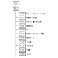
メインヘッダの構成を図4に示す。メインヘッダはCOD,QCDの必須マーカセグメントとCOC,QCC,RGN,POC,PPM,TLM,PLM,CRG,COMのオプションマーカセグメントで構成される。ここでSIZマーカには、タイルサイズの情報が記述されている。またCOMマーカはコメント等の情報を付加したいときに利用するマーカで、メインヘッダ、タイルヘッダの双方で使用することが可能である。
【0039】
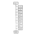
実際の符号データは、SOT(Start of Tile−part)マーカで始まり、タイルヘッダ、SOD(Start of data)マーカ、タイルデータ(符号)で構成される。これら画像全体に相当する符号データの後に、符号の終了を示すEOC(End of Codestream)マーカが付加される。メインヘッダはCOD,QCDの必須マーカセグメントとCOC,QCC,RGN,POC,PPM,TLM,PLM,CRG,COMのオプションマーカセグメントで構成される。
【0040】
タイルヘッダ構成を図5、図6に示す。図5は、タイルデータの先頭に付加されるマーカセグメント列で、COD,COC,QCD,QCC,RGN,POC,PPT,PLT,COMのマーカセグメントが使用可能である。一方、図6は、タイル内が複数に分割されている場合における分割されたタイル部分列の先頭に付加されるマーカセグメント列であり、POC,PPT,PLT,COMのマーカセグメントが使用可能である。タイルヘッダでは必須マーカセグメントはなく、すべてオプションである。
【0041】
DCレベルシフト部32は、画像信号がRGB信号値のような正の数(符号なし整数)である場合には、各信号値から信号のダイナミックレンジの半分を減算するレベルシフトを、逆変換では各信号値に信号のダイナミックレンジの半分を加算するレベルシフトを行う。なお、レベルシフトは画像信号がYCbCr信号におけるCb及びCrのような符号付き整数の場合には適用しない。
【0042】
JPEG2000で使用される色変換の方式はYCrCb等公知の技術なので説明は省略する。ウェーブレット変換としては9×7フィルタ、5×3フィルタのいずれを使用してもよい。いずれのフィルタも隣接画素とオーバーラップするフィルタである。隣接画素とオーバーラップするフィルタを使用する場合、量子化時にブロック歪が発生することがないという利点がある。なお、本例ではバンド境界においても隣接画素とのオーバーラップを行わせるために、バンドを構成する画素と併せて隣接する画素も必要な分だけバンドバッファ22に格納しておく。また、本例での量子化は後述するようにビットプレーン単位でポスト量子化を行うので、ここでは実施しない。
【0043】
JPEG2000のエントロピー符号化は、係数モデリング処理と算術符号化処理とで実行される。この方式は国際標準として周知であるため、詳しい説明は省略するが、以下の説明に必要な範囲で概要を示す。
【0044】
符号化方式は、EBCOT(Embedded Block Coding withOptimized runcation)と呼ばれるブロックベースのビットプレーン符号化である。EBCOTの特徴としては、各サブバンドを同一サイズにブロック分割して符号化する点と、ポスト処理による符号量制御が可能な点が挙げられる。EBCOTは、ブロック分割、係数モデリング、算術符号化という順で符号化が実行される。すなわち符号化は、Code blockと称するブロック単位で行われるのでまずウェーブレット係数はブロックに分割され係数モデリングされる。
【0045】
係数モデリングは、符号化対象となる多値Wavelet係数から、後段の2値算術符号化用のビットモデルを作成することが目的である。言い換えれば、符号化方法を決定する部分である。符号化対象となるWavelet 係数は正負の符号を持った整数(あるいは実数表現された整数)であり、それらを決められた順序で走査しながら、係数を絶対値表現したものに対して、上位ビットから下位ビットへと、ビットプレーン単位で処理を行う。ビットプレーン内の各ビットは3つの処理パスによって4つの符号化を行う。
【0046】
すなわち、まず、各Code blockにおけるビットプレーン上のビット走査順序は、垂直方向に4ビットまとめた単位でのラスター走査で行われる。符号化は、significance propagation pass(有意な係数が周囲にある有意でない係数の符号化)、magnitude refinement pass(有意な係数の符号化)、cleanup pass (残りの係数情報の符号化)の3つの処理パスで実行される。各処理パスで実行される符号化方法は、significance coding、sign coding、magnitude refinement coding、cleanupcodingの4種類がある。なお、ここで、“significance”とは、該当ビット(係数)が“有意である/ない”ことを示しており、以下のような解釈によって行われる。
【0047】
・有意である
これまでの符号化処理において注目係数が0でないとわかっている状態のこと。言い換えれば、すでに1であるビットを符号化済みであること。
【0048】
・有意でない
係数値が0であるか、0の可能性がある状態のこと。言い換えれば、未だ1であるビットを符号化していない状態のこと。
【0049】
符号化は、まず、ビットプレーンのMSBより走査を行い、ビットプレーン中に有意でない係数(0でないビット)が存在するかを判定する。有意である係数が登場するまでは3つの符号化処理パスは実行されない。有意でない係数のみで構成されるビットプレーンは、そのビットプレーン数をパケットヘッダに記述する。この値は復号時に利用され、有意でないビットプレーンを形成するために使われるとともに、係数のダイナミックレンジを復元するためにも必要である。有意であるビットが最初に登場したビットプレーンから実際の符号化は開始され、該ビットプレーンは、まずcleanup passで処理される。その後、下位のビットプレーンに対して順次、3つのパスを用いて処理が進められる。
【0050】
a)Significance propagation pass(有意な係数が周囲にある有意でない係数の符号化)
周囲の所定の8近傍の係数値に少なくとも1つの有意な係数があり、かつ注目する係数(X位置の係数値)がまだ有意でない場合にのみ、本パスにて処理される。それ以外の場合には本パスでは処理されない。
【0051】
b)Magnitude refinement pass(有意な係数の符号化)
注目する係数値(X)がすでに有意である状態の場合には、Magnituderefinement passによって処理される。本パスでは状態変化後(有意でない→有意である)に行う最初のパスであるかどうか、周囲の8近傍に有意な係数値が存在するかどうかによって、3つのコンテクストモデルを算出する。
【0052】
c)Cleanup pass(残りの係数情報の符号化)
上記2つのパス(Significance propagation passとMagnitude refinement pass)に該当しない残りのビットは、Cleanup passにて処理される。
【0053】
本パスで作成するコンテクストは、上記2つのパスのように8近傍の係数値を参照するコンテクストに加えて、ランレングス符号化用のコンテクストを作成する。符号化はランレングス符号化を行うかどうかを判断しながら符号化処理を行う。まず、垂直方向に連続する4つの係数値がすべて本パスに属しており、かつ4つすべての係数値における周囲の8近傍に有意な係数値が存在しないか否かを判断する。もし、本条件に該当する場合には、ランレングス符号化を行う。一方、本条件に該当しない場合には、4つの係数値の中に少なくとも1つの有意である係数が存在するので、各係数値をSignificancepropagation passで符号化する。ランレングス符号化は、4つの注目係数のビットがすべて0であるならば、シンボル0を符号化して終了する。そうでない場合にはシンボル1を符号化する。シンボル1を符号化した場合には、続いて4ビット中の最初の1になっているビット位置を2ビットで符号化し、その直後に正負の符号をSignificance propagation passと同様に符号化をする。ここでビット位置を示す2ビットを符号化する際にはUNIFORMコンテクストと称するコンテクストを用いる。これ以降の係数に対しては、Significance propagation passで符号化を行う。以上の処理が完了すると、次の4つの係数処理に入り、順次符号化処理を行う。なお、算術符号化については公知の技術であるので説明を省略する。
【0054】
次に、復号部24について説明する。図2(b)は、復号部24が実施する復号方式の機能ブロック図である。復号部24が実行するのは符号化部23の逆変換であり、符号化部23で使用するDCレベルシフト、色変換、ウェーブレット変換、エントロピー符号化の各処理の逆変換をそれぞれ実行する逆DCレベルシフト部36、逆色変換部37、ウェーブレット逆変換部38、エントロピー復号部39からなる。圧縮符号がタイル分割されている場合には、かかる処理を各タイルについて実行する。
【0055】
続いて、デジタル複写機1の動作について説明する。
【0056】
スキャナ3で読み込まれた、又は、ネットワーク4から送られてきた画像データは、バンド単位にバンドバッファ22に格納される。本例のバンドバッファ22が格納可能な画像データの容量は、600dpiの1画素あたり8ビットのR,G,Bの3色からなる画像データをA4サイズの4分の1だけ格納できる容量である。
【0057】
バンドバッファ22に格納された1バンド分の画像データは、符号化部23でタイル分割されて符号化される。すなわち符号化部23は、まず、画像データをタイル分割し、各タイルにおいて、図2(a)を参照して前述した処理を実行する。こうして得られた画像データの圧縮符号列はページメモリ25に格納され、その後、ハードディスク27に格納される。
【0058】
画像をプリンタエンジン2で出力する際には、ページメモリ25、ハードディスク27に格納されている圧縮符号列を復号部24で復号し、復号後の画像データはRGB→CMYK変換部28でCMYK色の画像データに変換し、K,M,C,Y色階調処理部29K,29M,29C,29YにおいてK,M,C,Y色がそれぞれ階調処理されて1200dpiで1画素あたり2値のデータに変換する。K,M,C色の画像データは静電潜像の書込タイミングを調節するためにラインメモリ16K,16M,16Cに一時格納され、転写材上でカラー画像を形成するタイミングにあわせて書込装置14K,14M,14Cへと送られる。
【0059】
本例における画像形成プロセスは周知の電子写真プロセスであるので動作の詳細は省略するが、それぞれK,M,C,Y色の乾式トナー像を形成するプロセスカートリッジ11K,11M,11C,11Yに対して書込装置14K,14M,14C,14Yが画像情報に応じた書込み光を発射すると、プロセスカートリッジ11K,11M,11C,11Yにおいて、帯電装置によって帯電させられた感光体上の被露光部分が除電されて静電潜像が形成される。この静電潜像に対して現像装置が乾式トナー粒子を画像部のみに選択的に付着させて可視像とし、この各色の可視像を転写ベルト12上に担持されて搬送される転写材(記録用紙やOHPなど)上に順次重ねていくことで得られたカラー画像を定着装置13で加熱・加圧して転写材上に固定する。
【0060】
次に、JPEG2000アルゴリズムで画像を圧縮した符号列をネットワーク4から受信して直接ページメモリに格納する場合の一連の処理について図7のフローチャートを参照して説明する。
【0061】
図7の処理は、その処理により本発明の画像処理装置を実施するものである。まず、デジタル複写機1の図示しないコントローラは、ネットワーク4からJPEG2000アルゴリズムで画像を圧縮した符号列を取り込む(ステップS1)。この際、デジタル複写機1の出力性能を超える高精細な符号列については600dpi出力に充分な階層までのデータのみを取り込み、また、符号列がページメモリに格納しきれない場合には、ポスト量子化を行い、符号量を削減する。
【0062】
そして、ページメモリ25に格納された符号列について、コントローラは、その復号に要する時間を算出して、復号時間算出手段を実現する(ステップS2)。この算出は、具体的には以下のようにして行う。
【0063】
▲1▼.メインヘッダあるいはタイルヘッダより、各ウェーブレット変換係数について、有意でないビットプレーンの数nを取得する。
【0064】
▲2▼.ついで各ウェーブレット変換係数について、有意なビットプレーンの数mを取得する。
【0065】
▲3▼.有意なビットプレーンのそれぞれについて、復号化に必要な時間BPi を算出する。この「復号化に必要な時間」としては、有意でないビットプレーンについては0秒、有意なビットプレーンについては上述した復号処理の3パスにおいて最も時間がかかるパスが選択された場合の処理時間を用いる。
【0066】
▲4▼.続いて各ビットプレーンの復号回数を計算する。具体的には、バンド単位の処理において1つのバンド内に存在するライン数をNB、ページメモリに格納された符号列のウェーブレット変換階層数(デコンポジションレベル)をNDとした時、
・NB>NDの場合にはNi1=1
・NB≦NDの場合にはNi1=[1+SU(ND/NB)]
(但し、“SU(x)”は、x以上である最小の自然数)
で求められるNi1 を計算する。同様に、ページメモリに格納された符号列が主走査方向にタイル分割されている場合における1タイルに含まれるライン数をNTとしたとき、
・NB>NTの場合にはNi2=[1+SU(NB/NT)]
・NB≦NTの場合にはNi2=[1+SU(NT/NB)]
(但し、“SU(x)”は、x以上である最小の自然数)
で求められるNi2を計算する。[2+SU(NB/NT)]は、高さNBのバンドを高さNTのタイルで埋め尽くす場合に必要なタイル数である。バンドの第1行とタイルの第1行とが同じ行であれば[1+SU(NB/NT)]でよいが、この行がずれることを考えて最悪の場合の[2+SU(NB/NT)]で計算する。Ni1とNi2のうちで大きな値を持つほうがNi すなわち各ビットプレーンの復号回数である。
【0067】
コントローラは、こうして得たNi及びBPiから、復号時間TとしてΣ(Ni×BPi)を計算する(ステップS2)。ここで、Σはインデックスiについての和である。
【0068】
ついで、Tが所定の時間Th1を超えているか否かが判定されて、第1の判定手段を実現する(ステップS3)。ここで時間th1は復号時間の上限であり、TがTh1を超えてしまった場合には、所定時間に所定画素のデータを書込装置14K,14M,14C,14Yに送ることができなくなる。
【0069】
T≦th1の場合には(ステップS3のN)、一連の処理は終了し、画像の出力が可能となるが、T>th1の場合には(ステップS3のY)、そのままでは復号時間がth1をオーバーする恐れが強いので、TがTh1以下となるように圧縮符号の変換による対応可能性を検討する(ステップS4)。具体的には、以下の▲1▼や▲2▼の検討を行う。
【0070】
▲1▼.ウェーブレット変換の階層数が大きすぎるために一つのビットプレーンを複数回復号する必要があり、このため、T>th1となってしまう場合(例えば1バンドに64ラインしか画像データを格納できないのに、8階層のウェーブレット変換がされているので1度に256ラインずつしか復号できない場合)や、あるいは、ウェーブレット変換の階層数が大きすぎるために復号化するビットプレーンが多くなり、このため、T>th1となってしまう場合(例えば6階層までならth1以内に処理できるのに、8階層の符号であるためにth1内に処理できない場合)には、圧縮符号を復号化部24で一部復号する。具体的には、ページメモリ25内の符号列をバンドバッファに順次読み出して、T>th1となるように途中の階層まで復号し、その後再びページメモリに格納する。この場合、階層変換に関係のない第一階層のウェーブレット係数については読み出す必要はないので、処理は高速に実行できる。
【0071】
▲2▼.タイルサイズが大きすぎるためにNTがNBを超え、あるいは、NT<NBであるがNBがNTで割り切れないために画像の位相がずれ、このため、同じビットプレーンを何回も読み出さねばならない場合には、タイルサイズの変換を行う。具体的には、各タイルをバンドバッファ22に順次読み出して画素値まで復号し、これをバンドバッファ22の幅に合ったタイルに変換し、あるいは、復号化部24において複数の復号器で並列処理を行なうことによって復号を行う場合にはタイルを細かく分割して復号処理に適したサイズ/タイル数に変換する。この場合、タイルを個々にバンドバッファ22に読み出せばよいので、タイルの高さがバンドの高さよりも高くても変換処理は容易に行うことができる。また全てのタイルについて変換を行わなくとも、一部のタイルについて細分割を実行すれば復号処理がth1以内に行える場合がある。
【0072】
そして、以上の▲1▼▲2▼の処理によって、T≦th1とすることができるか否かが判定され、第2の判定手段を実現する(ステップS5)。そして、T≦th1とできる場合には(ステップS5のY)、コントローラは圧縮符号を前述の▲1▼▲2▼のように変換し、符号変換手段を実現する(ステップS6)。T≦th1とできない場合には(ステップS5のN)、符号列を量子化又は復号+階調処理して時間内に復号できる圧縮符号に変換し、画像処理手段を実現する(ステップS7)。ステップS7において「量子化」とは、ビットプレーンの一部を削除することを、また、「復号+階調処理」とは、圧縮符号を一度復号して階調処理部29K、29M、29C、29Yにおいてディザ等の階調処理を施し、これをそのまま又は圧縮してページメモリ25に再格納することを意味する。本例では階調処理時に解像度が上がるために情報量が増えることがあるので、この場合には情報量を低減すべく画像の解像度を落とすこともありえる。階調処理された画像データをページメモリ25に格納する場合、復号化部24の処理をスルーできるので、高速に書込装置14K,14M,14C,14Yに画像データを送ることができる。なお、ステップS4の処理は基本的に画質劣化を伴わない処理であるので、一部のタイルや一部のウェーブレット係数についてのみ処理を実行してもよいが、ステップS7の処理のうち画質劣化を伴う処理については、1枚の画像内部での画質バラツキを抑えるために一律に処理を行うことが望ましい。以上で一連の処理が終了し、画像の出力が可能な状態となる。
【0073】
なお、本例のようにバンド単位に復号処理を実行する場合において、圧縮符号列がタイル分割されていない状態で復号時間を見積もったために、実際の出力処理においてバンドによっては復号時間が間に合わなくなる可能性がある。その場合には、その特定のバンドにおいてのみ復号するビットプレーンを制限して復号する。かかる場合にはバンド単位で若干画質に差が生じることになるが、1ページの出力としては復号時間がth1内に収まる程度に圧縮符号が調整されているために、その特定バンドにおいて強い量子化を実行する必要性は一般に低い。また、本例では最悪の処理パスで復号時間を見積もっているために、特定バンドにおいて処理時間が超過する可能性は低い。
【0074】
以上のようにして図7の処理を行なった符号列は、復号化部24で復号して、復号後の画像データはプリンタエンジン2で画像の形成に供される。
【0075】
以上説明したとおり、本デジタル複写機1によれば、取得したJPEG2000符号列の復号時間を算出し、この結果、復号処理が間に合わないと判定された場合には(ステップS3のY)、より短時間で復号できる符号列に変換するので(ステップS6)、画質を劣化させることなく短時間で復号することができる。
【0076】
また、この場合でも、符号列の変換によっても復号処理が間に合わないと判定される場合には、圧縮符号の変換は行わないため(ステップS5のN)、不必要な処理に時間をかけることがなく高速処理が可能である。
【0077】
さらに、この場合には(ステップS5のN)、圧縮符号の変換や量子化などの処理(ステップS7)を実行するため、復号処理が時間内に終了し、画像形成時のエラーを防止できる。さらに、最悪の処理パスを通った場合について復号時間を見積もっているので、バンド単位の処理においても一部のバンドの処理が間に合わないという可能性は低い。
【0078】
なお、本例では静止画像の処理を念頭において説明したが、本発明はこれに限定されるものではなく、様々な形態のデータについて適用することができる。例えば、音声情報については、本例で前述した処理からタイルに関する部分を除いた処理を1次元のウェーブレット変換について実行すれば適用可能である。
【0079】
【発明の効果】
本発明によれば、静止画像の符号列について、画質を劣化させることなく短時間で復号することができる。さらに、符号列の変換処理により短時間で符号列を復号することができないときは、符号列の変換処理で時間を要することを防止することができる。
【図面の簡単な説明】
【図1】本発明の一実施の形態であるデジタル複写機の概略構成を示す説明図である。
【図2】デジタル複写機の符号化部(a)、復号化部(b)の機能ブロック図である。
【図3】JPEG2000の符号フォーマットの概略構成を示す説明図である。
【図4】JPEG2000の符号フォーマットのメインヘッダの構成を示す説明図である。
【図5】JPEG2000の符号フォーマットのタイルヘッダの構成を示す説明図である。
【図6】JPEG2000の符号フォーマットのタイルヘッダの構成を示す説明図である。
【図7】デジタル複写機のコントローラが実行する処理のフローチャートである。
【符号の説明】
1 画像形成装置
2 プリンタエンジン
24 復号手段[0001]
BACKGROUND OF THE INVENTION
The present invention relates to an image processing apparatus and an image processing method.
[0002]
[Prior art]
In Patent Document 1, a time required for decoding frame encoded data is measured for a code string obtained by compressing and encoding moving image data, and the decoding time of the next frame encoded data to be decoded is calculated from the time data. And a technique for performing quantization on a frame predicted to be unable to be decoded within a predetermined time.
[0003]
[Patent Document 1]
JP 2002-51339 A
[0004]
[Problems to be solved by the invention]
In recent years, the standard of JPEG 2000, which is an international standard for image compression, has been gathered, and new standard compression codes for still images have begun to fly over the network. In connection with this, it is expected that an image processing apparatus built in an electrophotographic image forming apparatus or the like is required to perform processing by directly obtaining a compression code from a photographing apparatus such as a network or a digital camera.
[0005]
By the way, when the image forming apparatus directly receives a JPEG2000 code string from a network or a photographing device and performs image formation, there is a problem that the time required to decode the received code string is not known in advance. That is, when image data is encoded in the image forming apparatus and is decoded in the image forming apparatus, an approximate decoding time can be estimated at the time of encoding, and the tile division unit and the wavelet transform hierarchy can be estimated. Is also suitable for devices, so there is relatively little concern about delays in decoding processing, but there is no information at the time of encoding for compressed code strings obtained directly from networks or imaging devices. In addition, since there is a possibility that the code is not necessarily suitable for the device, the decoding process may be delayed. In particular, in JPEG2000, since tile division, wavelet transform layers, and the like are set relatively freely, there is a difficulty that JPEG does not have in that there are various types of compression codes.
[0006]
Then, in an image forming apparatus that needs to process a certain number of pixels per unit time as in the electrophotographic method, image formation stops halfway unless a predetermined number of pixels are decoded within a predetermined time, It is very important to understand the decoding time because it leads to waste of toner.
[0007]
In particular, when image formation is performed by decoding image data in band units, there is a possibility that the code block size or tile size of the received JPEG2000 code string exceeds the number of lines included in one band. . Generally, the number of lines that can be stored in the line buffer is limited, and even if the image data is decoded beyond the number of lines that can be stored, the portion that cannot be stored in the line buffer must be discarded.
[0008]
For example, when there is only a line buffer for 64 lines, (1) JPEG2000 code tiled in units of 128 × 128 pixels and (2) 7-layer wavelet transform (corresponding to 128 × 128 coefficients) are applied. Even if the image data for 128 lines is obtained by decoding the JPEG2000 code, the remaining 64 lines must be discarded because the number of lines that can be stored in the line buffer is 64 lines at a time. Therefore, in order to form an image for 128 lines, the same 128 lines are decoded twice, the first 64 lines are stored in the line buffer in the first time, and the latter 64 lines are stored in the line buffer in the second time. It must be done. In such a case, the processing time takes twice, and there is a high possibility that the decoding speed exceeds the processing speed.
[0009]
On the other hand, if the obtained JPEG2000 code is uniformly decoded and re-encoded, the above-mentioned difficulty is eliminated. However, since the decoding + re-encoding process generally takes time, high-speed decoding may be hindered, and direct There is a problem that high-speed processing cannot be performed even though the JPEG2000 code is acquired.
[0010]
On the other hand, in the technique disclosed in Patent Document 1, quantization is performed on a frame that is predicted to be undecidable within a predetermined time so that the decoding time of each frame constituting the moving image falls within the predetermined time. However, in a moving image, even if there is a frame that is strongly quantized by one frame in a continuous frame, there is not much visual problem, but in a still image, image degradation is easily noticeable. In addition, there is a problem that the processing for the hierarchy and tile size that the device does not assume is not touched. As described above, it is desirable to convert a still image that is easily noticeable in terms of image quality into a compressed code string having a short decoding time instead of quantization.
[0011]
In this case, there is also a problem that such conversion processing requires processing time.
[0012]
An object of the present invention is to be able to decode a code string such as a still image in a short time without degrading image quality.
[0013]
Another object of the present invention is to prevent the code string conversion process from taking time when the code string cannot be decoded in a short time by the code string conversion process.
[0014]
[Means for Solving the Problems]
The image processing apparatus according to the first aspect of the present invention decodes a code string for a code string obtained by dividing an image into one or a plurality of rectangular areas and hierarchically compression-coding each rectangular area independently. A decoding time calculating means for calculating a decoding time at the time of performing, a first determining means for determining whether or not a calculation time which is the calculated decoding time exceeds a predetermined time set in advance, and Code conversion means for converting the code string into a code string that can be decoded in a time shorter than the calculation time when it is determined that the calculation time exceeds the predetermined time;The code conversion means shortens the decoding time of the code string by changing the size of a part or all of the rectangular area constituting the code string.
[0015]
Therefore, a code string such as a still image can be decoded in a short time without degrading the image quality.
[0016]
An image processing apparatus according to a second aspect of the present invention decodes a code string for a code string obtained by dividing an image into one or a plurality of rectangular areas and hierarchically compression-coding each rectangular area independently. A decoding time calculating means for calculating a decoding time at the time of performing, a first determining means for determining whether or not a calculation time which is the calculated decoding time exceeds a predetermined time set in advance, and A code conversion means for converting the code string into a code string that can be decoded in a time shorter than the calculation time when it is determined that the calculation time exceeds the predetermined time; The decoding time of the code string is shortened by decoding a part of the wavelet transform coefficients constituting the code string.
[0017]
Claim 3The invention described inClaim 1 or 2In the image processing apparatus according to claim 1, when it is determined that the calculation time exceeds the predetermined time, the calculation time is set to the predetermined time by performing the conversion prior to conversion of the code string by the code conversion means. It further comprises second determination means for determining whether or not it can be exceeded, and the code conversion means determines that the calculation time can be prevented from exceeding the predetermined time by performing the conversion according to the determination. It is characterized in that the conversion is performed on the condition.
[0018]
Therefore, when the code string cannot be decoded in a short time by the code string conversion process, it is possible to prevent the code string conversion process from taking time.
[0019]
Claim 4The invention described inClaim 3In the image processing apparatus according to claim 1, when it is determined that the calculation time cannot exceed the predetermined time by performing the conversion by the second determination unit, one bit plane constituting the code string is determined. The image processing unit further includes an image processing unit that executes a process of deleting a portion or a process of decoding the code string once and performing a predetermined gradation process.
[0020]
Therefore, when the code string cannot be decoded in a short time by the code string conversion process, a process of deleting a part of the bit plane constituting the code string, or decoding the code string once and a predetermined gradation It is possible to prevent the time required for the code string conversion processing by performing the processing for performing the processing.
[0021]
Claim 5In the invention described in 1, the decoding time for decoding the code string is calculated for a code string obtained by dividing an image into one or a plurality of rectangular areas and hierarchically compression-coding each rectangular area independently. A decoding time calculating step, a first determination step for determining whether or not a calculation time that is the calculated decoding time exceeds a predetermined time set in advance, and the calculation time is set to the predetermined time by the determination. A code conversion step of converting the code string into a code string that can be decoded in a time shorter than the calculation time when it is determined that it exceedsAnd the code conversion step shortens the decoding time of the code string by changing a part or all of the size of the rectangular area constituting the code string.
[0022]
The invention according to claim 6 is a decoding method for decoding a code string for a code string obtained by dividing an image into one or a plurality of rectangular areas and hierarchically compression-coding each rectangular area independently. A decoding time calculating step for calculating time; a first determination step for determining whether or not a calculation time which is the calculated decoding time exceeds a predetermined time set in advance; and A code conversion step of converting the code string into a code string that can be decoded in a time shorter than the calculation time when it is determined that the predetermined time is exceeded, and the code conversion step constitutes the code string The code is decoded by decoding a part of the wavelet transform coefficient. It is characterized in that the decoding time of a sequence is shortened.
[0023]
The invention described in
[0024]
According to an eighth aspect of the present invention, in the image processing method according to the seventh aspect, when it is determined that the calculation time cannot exceed the predetermined time by performing the conversion in the second determination step. Further includes an image processing step of executing a process of deleting a part of the bit plane constituting the code string or a process of decoding the code string once and applying a predetermined gradation process. .
[0025]
Therefore,Claims 1-4The same operation and effect as the invention described in any one of the above can be achieved.
[0026]
DETAILED DESCRIPTION OF THE INVENTION
An embodiment of the present invention will be described.
[0027]
FIG. 1 is a block diagram showing a schematic configuration of a digital copying machine 1 according to the present embodiment. The digital copying machine 1 implements the image forming apparatus of the present invention, and includes a printer engine 2 that forms an image on a sheet or the like by a known electrophotographic process, and a
[0028]
The printer engine 2 includes a photoconductor, a developing device, a cleaning device, and a charging device, and a process for forming dry toner images of K, M, C, and Y (black, magenta, cyan, and yellow) colors. Electrostatic latent images of K, M, C, and Y color images are formed on the photoreceptors of the cartridges 11K, 11M, 11C, and 11Y, the transfer belt 12, the fixing device 13, and the process cartridges 11K, 11M, 11C, and 11Y.
[0029]
The digital copying machine 1 also includes an
[0030]
In FIG. 1, a
[0031]
The digital copying machine 1 can receive image data from a predetermined network 4 such as a LAN via a communication interface (not shown). When the image data input via the network 4 is data in the PDL (page description language) format, the
[0032]
The
[0033]
The
[0034]
The RGB →
[0035]
The K, M, and C writing data are stored in the
[0036]
Next, the encoding method performed by the
[0037]
A schematic configuration of the JPEG 2000 code format is shown in FIG. The code format starts with an SOC (Start of Codestream) marker indicating the start of code data. The SOC marker is followed by a main header describing coding parameters, quantization parameters, etc., followed by actual code data.
[0038]
The structure of the main header is shown in FIG. The main header is composed of COD and QCD essential marker segments and COC, QCC, RGN, POC, PPM, TLM, PLM, CRG, and COM optional marker segments. Here, tile size information is described in the SIZ marker. The COM marker is a marker used when adding information such as a comment, and can be used in both the main header and the tile header.
[0039]
The actual code data starts with an SOT (Start of Tile-part) marker, and includes a tile header, an SOD (Start of data) marker, and tile data (code). After the code data corresponding to the entire image, an EOC (End of Codestream) marker indicating the end of the code is added. The main header is composed of COD and QCD essential marker segments and COC, QCC, RGN, POC, PPM, TLM, PLM, CRG, and COM optional marker segments.
[0040]
The tile header configuration is shown in FIGS. FIG. 5 shows a marker segment sequence added to the head of tile data. COD, COC, QCD, QCC, RGN, POC, PPT, PLT, and COM marker segments can be used. On the other hand, FIG. 6 shows a marker segment sequence added to the head of the divided tile partial sequence when the tile is divided into a plurality of segments, and marker segments of POC, PPT, PLT, and COM can be used. . There is no mandatory marker segment in the tile header, all are optional.
[0041]
When the image signal is a positive number (unsigned integer) such as an RGB signal value, the DC
[0042]
Since the color conversion method used in JPEG2000 is a known technique such as YCrCb, description thereof is omitted. Any of 9 × 7 filters and 5 × 3 filters may be used as the wavelet transform. Both filters are filters that overlap with adjacent pixels. When a filter that overlaps adjacent pixels is used, there is an advantage that block distortion does not occur during quantization. In this example, in order to overlap the adjacent pixels even at the band boundary, the necessary number of adjacent pixels together with the pixels constituting the band are stored in the
[0043]
JPEG2000 entropy coding is performed by coefficient modeling processing and arithmetic coding processing. Since this method is well known as an international standard, a detailed description is omitted, but an outline will be given to the extent necessary for the following description.
[0044]
The encoding method is block-based bit-plane encoding called EBCOT (Embedded Block Coding with Optimized RUNNATION). The characteristics of EBCOT are that each subband is divided into blocks of the same size and encoded, and the amount of code can be controlled by post processing. EBCOT is encoded in the order of block division, coefficient modeling, and arithmetic encoding. That is, since encoding is performed in units of blocks called code blocks, first, wavelet coefficients are divided into blocks and coefficient modeling is performed.
[0045]
The purpose of coefficient modeling is to create a bit model for binary arithmetic coding at the subsequent stage from the multilevel Wavelet coefficient to be encoded. In other words, it is a part for determining the encoding method. The Wavelet coefficient to be encoded is an integer having a positive or negative sign (or an integer expressed as a real number), and the higher order bit for the coefficient expressed in absolute value while scanning in a predetermined order Process from bit to lower bits in bit plane units. Each bit in the bit plane is encoded four times by three processing passes.
[0046]
That is, first, the bit scanning order on the bit plane in each code block is performed by raster scanning in a unit in which four bits are grouped in the vertical direction. There are three types of encoding: significance propagation pass (encoding of insignificant coefficients around which a significant coefficient is present), magnified refinement pass (encoding of significant coefficients), and cleanup pass (encoding of remaining coefficient information). Run in the pass. There are four types of encoding methods executed in each processing pass: significance coding, sign coding, magnified refinement coding, and cleanup coding. Here, “significance” indicates that the corresponding bit (coefficient) is “significant / not significant”, and is interpreted by the following interpretation.
[0047]
・ Significant
A state in which the attention coefficient is known to be not 0 in the encoding process so far. In other words, the bits that are already 1 have been encoded.
[0048]
・ Not significant
A state where the coefficient value is 0 or possibly 0. In other words, the bit that is still 1 is not encoded.
[0049]
In encoding, first, scanning is performed from the MSB of the bit plane, and it is determined whether or not a non-significant coefficient (non-zero bit) exists in the bit plane. The three encoding processing passes are not executed until a significant coefficient appears. For bit planes composed only of insignificant coefficients, the number of bit planes is described in the packet header. This value is used at the time of decoding and is used to form an insignificant bit plane and is also necessary to restore the dynamic range of the coefficients. The actual encoding is started from the bit plane in which a significant bit first appears, and the bit plane is first processed with a cleanup pass. Thereafter, the processing is sequentially performed on the lower bit planes using three passes.
[0050]
a) Significance propagation pass (encoding of insignificant coefficients with significant coefficients around)
The processing is performed in this pass only when there are at least one significant coefficient among the coefficient values in the vicinity of the predetermined eight, and the coefficient of interest (the coefficient value at the X position) is not yet significant. In other cases, it is not processed in this pass.
[0051]
b) Magnitude refinement pass (significant coefficient encoding)
When the coefficient value (X) to be noticed is already significant, it is processed by Magnitude refinement pass. In this pass, three context models are calculated depending on whether this is the first pass after state change (not significant → significant) and whether there are significant coefficient values in the vicinity of the surrounding eight.
[0052]
c) Cleanup pass (encoding of remaining coefficient information)
The remaining bits that do not correspond to the above two paths (Significance propagation pass and Magnitude refinement pass) are processed by the Cleanup pass.
[0053]
The context created by this pass creates a context for run-length encoding in addition to the context referring to the coefficient values in the vicinity of 8 as in the above two passes. Encoding is performed while determining whether to perform run-length encoding. First, it is determined whether all four coefficient values that are continuous in the vertical direction belong to this path, and there are no significant coefficient values in the vicinity of the surrounding eight of all four coefficient values. If this condition is met, run-length encoding is performed. On the other hand, when this condition is not met, at least one significant coefficient is present among the four coefficient values, and therefore, each coefficient value is encoded with the Significancepropagation pass. Run-length encoding ends with encoding symbol 0 if all four bits of the coefficient of interest are zero. Otherwise, symbol 1 is encoded. When the symbol 1 is encoded, the bit position of the first 1 in 4 bits is encoded with 2 bits, and immediately after that, the positive and negative codes are encoded in the same manner as the signature of the propagation of the propagation. Here, when encoding 2 bits indicating a bit position, a context called UNIFORM context is used. The coefficients after this are encoded by the signature propagation pass. When the above process is completed, the following four coefficient processes are entered, and the encoding process is sequentially performed. Since arithmetic coding is a known technique, description thereof is omitted.
[0054]
Next, the
[0055]
Next, the operation of the digital copying machine 1 will be described.
[0056]
Image data read by the
[0057]
The image data for one band stored in the
[0058]
When the image is output by the printer engine 2, the compression code string stored in the
[0059]
Since the image forming process in this example is a well-known electrophotographic process, the details of the operation are omitted, but for the process cartridges 11K, 11M, 11C, and 11Y that form dry toner images of K, M, C, and Y colors, respectively. When the
[0060]
Next, a series of processing when a code string obtained by compressing an image with the JPEG2000 algorithm is received from the network 4 and directly stored in the page memory will be described with reference to the flowchart of FIG.
[0061]
The processing of FIG. 7 is to implement the image processing apparatus of the present invention by the processing. First, a controller (not shown) of the digital copying machine 1 takes in a code string obtained by compressing an image using the JPEG2000 algorithm from the network 4 (step S1). At this time, for a high-definition code string exceeding the output performance of the digital copying machine 1, only data up to a hierarchy sufficient for 600 dpi output is fetched, and when the code string cannot be stored in the page memory, post-quantum The code amount is reduced.
[0062]
Then, for the code string stored in the
[0063]
(1). The number n of insignificant bit planes is obtained for each wavelet transform coefficient from the main header or tile header.
[0064]
(2). Next, the number m of significant bit planes is acquired for each wavelet transform coefficient.
[0065]
(3). For each significant bit plane, the time BPi required for decoding is calculated. As this “time required for decoding”, 0 second is used for insignificant bit planes, and for significant bit planes, the processing time when the path that takes the longest time in the above-described three passes of decoding processing is selected is used. .
[0066]
(4). Subsequently, the number of decoding times of each bit plane is calculated. Specifically, when the number of lines existing in one band is NB and the number of wavelet transform layers (decomposition level) of the code string stored in the page memory is ND in the processing in units of bands,
・ If NB> ND, Ni1= 1
・ If NB ≦ ND, Ni1= [1 + SU (ND / NB)]
(Where “SU (x)” is the smallest natural number that is greater than or equal to x)
Calculate Ni1 obtained in step (1). Similarly, when the number of lines included in one tile when the code string stored in the page memory is tiled in the main scanning direction is NT,
・ If NB> NT, Ni2= [1 + SU (NB / NT)]
・ If NB ≦ NT, Ni2= [1 + SU (NT / NB)]
(Where “SU (x)” is the smallest natural number that is greater than or equal to x)
N required byi2Calculate [2 + SU (NB / NT)] is the number of tiles necessary when a band of height NB is filled with tiles of height NT. If the first row of the band and the first row of the tile are the same row, [1 + SU (NB / NT)] may be used, but the worst case [2 + SU (NB / NT)] considering that this row is shifted. Calculate with Ni1And Ni2Of these, the larger value is Ni, that is, the number of decoding times of each bit plane.
[0067]
The controller N thus obtainediAnd BPiFrom Σ (Ni× BPi) Is calculated (step S2). Where Σ is the sum for index i.
[0068]
Next, it is determined whether or not T exceeds a predetermined time Th1, and the firstJudgmentMeans are realized (step S3). Here, the time th1 is the upper limit of the decoding time, and when T exceeds Th1, data of a predetermined pixel cannot be sent to the
[0069]
If T ≦ th1 (N in step S3), the series of processing ends and the image can be output. If T> th1 (Y in step S3), the decoding time is th1 as it is. Therefore, the possibility of dealing with compression code conversion is examined so that T is equal to or less than Th1 (step S4). Specifically, the following (1) and (2) are examined.
[0070]
(1). Since the number of wavelet transform layers is too large, it is necessary to decode one bit plane multiple times. For this reason, when T> th1 (for example, although only 64 lines can be stored in one band, 8) Since wavelet transform of 8 layers is performed, only 256 lines can be decoded at one time), or because the number of wavelet transform layers is too large, the number of bit planes to be decoded increases. Therefore, T> th1 (For example, if it can be processed within th1 if it is up to 6 layers but cannot be processed within th1 because it is an 8 layer code), the
[0071]
(2). If the tile size is too large, NT exceeds NB, or if NT <NB but NB cannot be divided by NT, the phase of the image shifts, so the same bit plane must be read many times Performs tile size conversion. Specifically, each tile is sequentially read out to the
[0072]
Then, through the processes (1) and (2), it is determined whether or not T ≦ th1 can be established, and the second determination means is realized (step S5). If T ≦ th1 is satisfied (Y in step S5), the controller converts the compression code as described in the above (1) and (2) to realize the code conversion means.(Step S6).If T ≦ th1 cannot be satisfied (N in step S5), the code string is converted into a compression code that can be decoded in time by quantization or decoding + gradation processing, and an image processing means is realized (step S7). In step S7, “quantization” means that a part of the bit plane is deleted, and “decoding + gradation processing” means that the compression code is decoded once and the
[0073]
In addition, when decoding processing is performed in units of bands as in this example, the decoding time is estimated in a state where the compressed code string is not tile-divided, so the decoding time may not be in time for some bands in the actual output processing. There is sex. In that case, decoding is performed by limiting bit planes to be decoded only in the specific band. In such a case, there is a slight difference in image quality on a band basis. However, since the compression code is adjusted so that the decoding time is within th1 as the output of one page, strong quantization is performed in that specific band. The need to perform is generally low. In this example, since the decoding time is estimated using the worst processing path, the possibility that the processing time will be exceeded in a specific band is low.
[0074]
7 is decoded by the
[0075]
As described above, according to the digital copying machine 1, the decoding time of the acquired JPEG2000 code string is calculated, and as a result, if it is determined that the decoding process is not in time (Y in step S3), the decoding time is shorter. Since it is converted into a code string that can be decoded in time (step S6), it can be decoded in a short time without degrading the image quality.
[0076]
Even in this case, the decoding process is not in time due to the conversion of the code string.WhenIn the case of determination, since compression code conversion is not performed (N in step S5), high-speed processing is possible without taking time for unnecessary processing.
[0077]
Further, in this case (N in step S5), processing such as compression code conversion and quantization (step S7) is executed, so that the decoding process is completed in time, and errors during image formation can be prevented. Furthermore, since the decoding time is estimated for the case of passing through the worst processing path, there is a low possibility that the processing of some bands will not be in time even in the processing of each band.
[0078]
In this example, the processing of still images has been described in mind, but the present invention is not limited to this and can be applied to various forms of data. For example, the audio information can be applied by executing processing for the one-dimensional wavelet transform by removing the portion related to the tile from the processing described above in this example.
[0079]
【The invention's effect】
According to the present invention,The still image code string can be decoded in a short time without degrading the image quality.further,When the code string cannot be decoded in a short time by the code string conversion process, it is possible to prevent the code string conversion process from taking time.
[Brief description of the drawings]
FIG. 1 is an explanatory diagram showing a schematic configuration of a digital copying machine according to an embodiment of the present invention.
FIG. 2 is a functional block diagram of an encoding unit (a) and a decoding unit (b) of the digital copying machine.
FIG. 3 is an explanatory diagram showing a schematic configuration of a JPEG2000 code format;
FIG. 4 is an explanatory diagram showing a configuration of a main header of a JPEG 2000 code format.
FIG. 5 is an explanatory diagram illustrating a configuration of a tile header of a JPEG2000 code format.
FIG. 6 is an explanatory diagram illustrating a configuration of a tile header of a JPEG2000 code format.
FIG. 7 is a flowchart of processing executed by a controller of the digital copying machine.
[Explanation of symbols]
1 Image forming device
2 Printer engine
24 Decoding means
Claims (8)
前記算出した復号時間である算出時間が予め設定された所定時間を超過するか否かを判定する第1の判定手段と、
前記判定により前記算出時間が前記所定時間を超過すると判断したときは、前記符号列を前記算出時間より少ない時間で前記復号が行なえる符号列に変換する符号変換手段と、を備え、
前記符号変換手段は、前記符号列を構成する前記矩形領域の一部または全部のサイズを変更することによって前記符号列の復号時間を短縮することを特徴とする画像処理装置。 Decoding time calculation means for dividing a picture into one or a plurality of rectangular areas and calculating a decoding time for decoding the code string for a code string obtained by hierarchically compressing and encoding each rectangular area independently; ,
First determination means for determining whether or not a calculation time which is the calculated decoding time exceeds a predetermined time set in advance;
When it is determined by the determination that the calculation time exceeds the predetermined time, code conversion means for converting the code string into a code string that can be decoded in a time shorter than the calculation time, and
The image processing apparatus, wherein the code conversion means shortens the decoding time of the code string by changing a size of a part or all of the rectangular area constituting the code string.
前記算出した復号時間である算出時間が予め設定された所定時間を超過するか否かを判定する第1の判定手段と、First determination means for determining whether or not a calculation time that is the calculated decoding time exceeds a predetermined time set in advance;
前記判定により前記算出時間が前記所定時間を超過すると判断したときは、前記符号列を前記算出時間より少ない時間で前記復号が行なえる符号列に変換する符号変換手段と、を備え、When it is determined by the determination that the calculation time exceeds the predetermined time, code conversion means for converting the code string into a code string that can be decoded in a time shorter than the calculation time, and
前記符号変換手段は、前記符号列を構成するウェーブレット変換係数の一部を復号することによって前記符号列の復号時間を短縮することを特徴とする画像処理装置。The code conversion means shortens the decoding time of the code string by decoding a part of the wavelet transform coefficients constituting the code string.
前記符号変換手段は、前記判定により前記変換を行なうことで前記算出時間が前記所定時間を超過しないようにできると判断したことを条件に、前記変換を行なうことを特徴とする請求項1又は2に記載の画像処理装置。The code conversion means performs the conversion on the condition that it is determined that the calculation time does not exceed the predetermined time by performing the conversion by the determination. An image processing apparatus according to 1.
前記算出した復号時間である算出時間が予め設定された所定時間を超過するか否かを判定する第1の判定ステップと、A first determination step of determining whether or not a calculation time which is the calculated decoding time exceeds a predetermined time set in advance;
前記判定により前記算出時間が前記所定時間を超過すると判断したときは、前記符号列を前記算出時間より少ない時間で前記復号が行なえる符号列に変換する符号変換ステップとを有し、A code conversion step for converting the code string into a code string that can be decoded in a time shorter than the calculation time when it is determined by the determination that the calculation time exceeds the predetermined time;
前記符号変換ステップは、前記符号列を構成する前記矩形領域の一部または全部のサイズを変更することによって前記符号列の復号時間を短縮することを特徴とする画像処理方法。In the image conversion method, the code conversion step shortens the decoding time of the code string by changing the size of a part or all of the rectangular area constituting the code string.
前記算出した復号時間である算出時間が予め設定された所定時間を超過するか否かを判定する第1の判定ステップと、A first determination step of determining whether or not a calculation time which is the calculated decoding time exceeds a predetermined time set in advance;
前記判定により前記算出時間が前記所定時間を超過すると判断したときは、前記符号列を前記算出時間より少ない時間で前記復号が行なえる符号列に変換する符号変換ステップとを有し、A code conversion step for converting the code string into a code string that can be decoded in a time shorter than the calculation time when it is determined by the determination that the calculation time exceeds the predetermined time;
前記符号変換ステップは、前記符号列を構成するウェーブレット変換係数の一部を復号することによって前記符号列の復号時間を短縮することを特徴とする画像処理方法。The code conversion step is characterized in that a decoding time of the code string is shortened by decoding a part of wavelet transform coefficients constituting the code string.
前記符号変換ステップは、前記判定により前記変換を行なうことで前記算出時間が前記所定時間を超過しないようにできると判断したことを条件に前記変換を行なうことを特徴とする請求項5又は6に記載の画像処理方法。If it is determined that the calculation time exceeds the predetermined time, whether or not the calculation time does not exceed the predetermined time by performing the conversion prior to the conversion of the code string in the code conversion step. A second determination step for determining
Said code conversion step, to claim 5 or 6, characterized by performing said conversion on condition that the calculated time by performing the conversion by the determining has determined that it so as not to exceed the predetermined time The image processing method as described.
Priority Applications (1)
| Application Number | Priority Date | Filing Date | Title |
|---|---|---|---|
| JP2003005508A JP4046223B2 (en) | 2003-01-14 | 2003-01-14 | Image processing apparatus and image processing method |
Applications Claiming Priority (1)
| Application Number | Priority Date | Filing Date | Title |
|---|---|---|---|
| JP2003005508A JP4046223B2 (en) | 2003-01-14 | 2003-01-14 | Image processing apparatus and image processing method |
Publications (3)
| Publication Number | Publication Date |
|---|---|
| JP2004221832A JP2004221832A (en) | 2004-08-05 |
| JP2004221832A5 JP2004221832A5 (en) | 2006-05-11 |
| JP4046223B2 true JP4046223B2 (en) | 2008-02-13 |
Family
ID=32896152
Family Applications (1)
| Application Number | Title | Priority Date | Filing Date |
|---|---|---|---|
| JP2003005508A Expired - Fee Related JP4046223B2 (en) | 2003-01-14 | 2003-01-14 | Image processing apparatus and image processing method |
Country Status (1)
| Country | Link |
|---|---|
| JP (1) | JP4046223B2 (en) |
Families Citing this family (2)
| Publication number | Priority date | Publication date | Assignee | Title |
|---|---|---|---|---|
| JP2006262208A (en) * | 2005-03-17 | 2006-09-28 | Ricoh Co Ltd | Information processing system, method and program for predicting expansion time of encoded file, and information recording medium |
| JP4579049B2 (en) * | 2005-05-11 | 2010-11-10 | 三菱電機株式会社 | Image decoding apparatus and image decoding system |
-
2003
- 2003-01-14 JP JP2003005508A patent/JP4046223B2/en not_active Expired - Fee Related
Also Published As
| Publication number | Publication date |
|---|---|
| JP2004221832A (en) | 2004-08-05 |
Similar Documents
| Publication | Publication Date | Title |
|---|---|---|
| JP2009543423A (en) | Video encoding / decoding method and apparatus | |
| JP2004104650A (en) | Image processor, image reader, image forming device, program for image processing and storage medium | |
| JPH0750758A (en) | Encoder | |
| JP2004248268A (en) | Image processor, image forming apparatus, image decoder, image processing method, program, and memory medium | |
| JPH0514562A (en) | Digital copying machine | |
| JP4046223B2 (en) | Image processing apparatus and image processing method | |
| JP2004248271A (en) | Image processor, image forming apparatus, image processing method, program, and memory medium | |
| JP2006014086A (en) | Moving image encoding apparatus and moving image encoding method | |
| JP4315928B2 (en) | Image processing apparatus and image processing method | |
| JP2004228964A (en) | Image processor, image forming apparatus, program, and storage medium | |
| JP4093871B2 (en) | Image forming apparatus, program, and storage medium | |
| JP3732674B2 (en) | Color image compression method and color image compression apparatus | |
| JP4111863B2 (en) | Image processing apparatus, image forming apparatus, image processing program, and storage medium | |
| JP3189511B2 (en) | Encoding device | |
| JP4050157B2 (en) | Image processing apparatus, image processing method, program, and storage medium | |
| JP2004236220A (en) | Encoder, information management apparatus, decoder, image forming apparatus, encoding program, information management program, decoding program, and storage medium | |
| JP4014087B2 (en) | Image processing apparatus, image processing method, program, and storage medium | |
| JP4017109B2 (en) | Image processing apparatus, image processing method, image forming apparatus, program, and recording medium | |
| JP5078199B2 (en) | Image encoding apparatus and method, program code, and storage medium | |
| JP4159259B2 (en) | Image processing apparatus, image processing method, program for causing computer to execute image processing method, and computer-readable recording medium storing the program | |
| JP4010452B2 (en) | Image processing apparatus and image processing method | |
| JP2004235935A (en) | Image processing apparatus, image forming apparatus, program, and storage medium | |
| JP3784755B2 (en) | Image processing apparatus, image forming apparatus, program, and storage medium | |
| JP2005130244A (en) | Image processing apparatus and image processing method | |
| JP5250591B2 (en) | Image compression apparatus and method, and image forming apparatus |
Legal Events
| Date | Code | Title | Description |
|---|---|---|---|
| RD04 | Notification of resignation of power of attorney |
Free format text: JAPANESE INTERMEDIATE CODE: A7424 Effective date: 20041008 |
|
| A621 | Written request for application examination |
Free format text: JAPANESE INTERMEDIATE CODE: A621 Effective date: 20050824 |
|
| A521 | Written amendment |
Free format text: JAPANESE INTERMEDIATE CODE: A821 Effective date: 20050829 |
|
| RD02 | Notification of acceptance of power of attorney |
Free format text: JAPANESE INTERMEDIATE CODE: A7422 Effective date: 20050829 |
|
| A521 | Written amendment |
Free format text: JAPANESE INTERMEDIATE CODE: A523 Effective date: 20060317 |
|
| RD05 | Notification of revocation of power of attorney |
Free format text: JAPANESE INTERMEDIATE CODE: A7425 Effective date: 20060925 |
|
| A977 | Report on retrieval |
Free format text: JAPANESE INTERMEDIATE CODE: A971007 Effective date: 20070601 |
|
| A131 | Notification of reasons for refusal |
Free format text: JAPANESE INTERMEDIATE CODE: A131 Effective date: 20070619 |
|
| A521 | Written amendment |
Free format text: JAPANESE INTERMEDIATE CODE: A523 Effective date: 20070820 |
|
| A131 | Notification of reasons for refusal |
Free format text: JAPANESE INTERMEDIATE CODE: A131 Effective date: 20070926 |
|
| A521 | Written amendment |
Free format text: JAPANESE INTERMEDIATE CODE: A523 Effective date: 20071023 |
|
| TRDD | Decision of grant or rejection written | ||
| A01 | Written decision to grant a patent or to grant a registration (utility model) |
Free format text: JAPANESE INTERMEDIATE CODE: A01 Effective date: 20071114 |
|
| A61 | First payment of annual fees (during grant procedure) |
Free format text: JAPANESE INTERMEDIATE CODE: A61 Effective date: 20071115 |
|
| FPAY | Renewal fee payment (event date is renewal date of database) |
Free format text: PAYMENT UNTIL: 20101130 Year of fee payment: 3 |
|
| FPAY | Renewal fee payment (event date is renewal date of database) |
Free format text: PAYMENT UNTIL: 20111130 Year of fee payment: 4 |
|
| FPAY | Renewal fee payment (event date is renewal date of database) |
Free format text: PAYMENT UNTIL: 20111130 Year of fee payment: 4 |
|
| FPAY | Renewal fee payment (event date is renewal date of database) |
Free format text: PAYMENT UNTIL: 20121130 Year of fee payment: 5 |
|
| FPAY | Renewal fee payment (event date is renewal date of database) |
Free format text: PAYMENT UNTIL: 20131130 Year of fee payment: 6 |
|
| LAPS | Cancellation because of no payment of annual fees |