JP4045960B2 - Imaging apparatus and method, recording medium, and program - Google Patents
Imaging apparatus and method, recording medium, and program Download PDFInfo
- Publication number
- JP4045960B2 JP4045960B2 JP2003013686A JP2003013686A JP4045960B2 JP 4045960 B2 JP4045960 B2 JP 4045960B2 JP 2003013686 A JP2003013686 A JP 2003013686A JP 2003013686 A JP2003013686 A JP 2003013686A JP 4045960 B2 JP4045960 B2 JP 4045960B2
- Authority
- JP
- Japan
- Prior art keywords
- vehicle
- imaging
- automobile
- unit
- setting
- Prior art date
- Legal status (The legal status is an assumption and is not a legal conclusion. Google has not performed a legal analysis and makes no representation as to the accuracy of the status listed.)
- Expired - Fee Related
Links
Images


Landscapes
- Camera Bodies And Camera Details Or Accessories (AREA)
- Closed-Circuit Television Systems (AREA)
Description
【0001】
【発明の属する技術分野】
本発明は撮像装置および方法、記録媒体、並びにプログラムに関し、特に、自動車内に設けられた後方確認カメラによって、駐車時に車外を監視することができるようにした撮像装置および方法、記録媒体、並びにプログラムに関する。
【0002】
【従来の技術】
ホームセキュリティシステムとして、撮像装置から送信される監視画像をモニタTV(Television)に表示することが提案されている(例えば、特許文献1参照)。
【0003】
また、赤外線センサと画像センサが組み合わされた監視装置が、人体の有無および画策の有無を判定することにより、監視領域内に進入した人体を検出することが提案されている(例えば、特許文献2参照)。
【0004】
これらの特許文献1および特許文献2に記載の発明においては、主に、特定の場所または特定の異常(イベント)が検出される。
【0005】
【特許文献1】
特開平8−124078号公報
【特許文献2】
特開2000−339554号公報
【0006】
【発明が解決しようとする課題】
しかしながら、これらの特許文献1および特許文献2に記載されている発明では、設置の際の調整が煩わしく、さらに、一度設置すると、別の場所にセンサ(撮像装置または監視装置)を移動することが困難であるという課題があった。
【0007】
また、従来使用されている無線カメラは、バッテリ駆動により、常時、画像および音声等を送信し続ける為、バッテリが短時間しか持たないという課題があった。
【0008】
本発明はこのような状況に鑑みてなされたものであり、自動車内に設けられた後方確認カメラによって駐車時に車外を監視することができるようにするものである。
【0009】
【課題を解決するための手段】
本発明の撮像装置は、自動車の内部であって、自動車の窓から外部を撮影できる位置に取り付けられる撮像手段と、自動車周辺を監視する監視モードにおける撮像手段の撮像の方向をユーザによって指定された方向に設定する方向設定手段と、自動車が後方に移動する第1の使用状態にあるのか、または自動車が移動の用途に使用されない第2の使用状態にあるのかを判定する判定手段と、撮像手段の撮像の方向を、自動車が第1の使用状態にある場合、自動車の後方になるように制御するとともに、自動車が第2の使用状態にある場合、方向設定手段により設定された監視モードにおける方向になるように制御する方向制御手段とを備えることを特徴とする。
【0010】
自動車の窓を介して自動車の外部の物体を検出する検出手段と、検出手段により移動する物体が検出されないとき、撮像手段に対する電力の供給を禁止し、移動する物体が検出されたとき、撮像手段に対する電力の供給を許可する電力供給制御手段とをさらに備えることができる。
【0011】
検出手段が移動する物体を検出した場合、方向制御手段は、物体を追跡するように撮像手段の撮像方向を制御することができる。
【0012】
撮像手段に対して電力を供給する電池をさらに備え、電力供給制御手段は、電池の残容量が基準値以下になった場合、電池に代えて、自動車のバッテリからの電力を供給することができる。
【0013】
撮像手段により撮像された画像を送信する送信手段と、撮像手段により撮像された画像の送信先を、自動車が第1の使用状態にある場合、自動車の内部に配置される第1の表示装置に設定し、自動車が第2の使用状態にある場合、自動車の外部に配置される第2の表示装置に設定する送信先設定手段をさらに備えることができる。
【0014】
前記判定手段は、自動車のエンジンキーとトランスミッションギアの状態に基づいて、第1の使用状態と第2の使用状態を判定するようにすることがでできる。
【0015】
本発明の撮像方法は、自動車周辺を監視する監視モードにおける撮像手段の撮像の方向をユーザによって指定された方向に設定する方向設定ステップと、自動車が後方に移動する第1の使用状態にあるのか、または自動車が移動の用途に使用されない第2の使用状態にあるのかを判定する判定ステップと、撮像手段の撮像の方向を、自動車が第1の使用状態にある場合、自動車の後方になるように制御するとともに、自動車が第2の使用状態にある場合、方向設定手段により設定された監視モードにおける方向になるように制御する方向制御ステップとを含むことを特徴とする。
【0016】
本発明の記録媒体に記録されているプログラムは、自動車周辺を監視する監視モードにおける撮像手段の撮像の方向をユーザによって指定された方向に設定する方向設定ステップと、自動車が後方に移動する第1の使用状態にあるのか、または自動車が移動の用途に使用されない第2の使用状態にあるのかを判定する判定ステップと、撮像手段の撮像の方向を、自動車が第1の使用状態にある場合、自動車の後方になるように制御するとともに、自動車が第2の使用状態にある場合、方向設定手段により設定された監視モードにおける方向になるように制御する方向制御ステップとを含むことを特徴とする。
【0017】
本発明のプログラムは、自動車周辺を監視する監視モードにおける撮像手段の撮像の方向をユーザによって指定された方向に設定する方向設定ステップと、自動車が後方に移動する第1の使用状態にあるのか、または自動車が移動の用途に使用されない第2の使用状態にあるのかを判定する判定ステップと、撮像手段の撮像の方向を、自動車が第1の使用状態にある場合、自動車の後方になるように制御するとともに、自動車が第2の使用状態にある場合、方向設定手段により設定された監視モードにおける方向になるように制御する方向制御ステップとをコンピュータに実行させることを特徴とする。
【0018】
本発明においては、撮像手段の撮像の方向が、自動車が第1の使用状態にある場合、自動車の後方になるように制御され、自動車が第2の使用状態にある場合、設定された監視モードにおける方向になるように制御される。
【0019】
【発明の実施の形態】
以下、図を参照して、本発明の実施の形態について説明する。まず、図1を参照して、本発明の撮像装置の第1の実施の形態について説明する。
【0020】
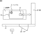
自動車1は、家の壁21と壁22で囲まれた駐車スペースに入る場合であり、壁21と平行に、壁22に向かって後進する。自動車1の内部の後方には、撮影装置11が、その撮影方向が任意の方向に向けられるように取り付けられている。撮影装置11によって撮影された映像は、自動車1の内部の前方であってハンドル2の左側(助手席側)に設けられた受信表示装置12に送信され、表示される。したがって、ドライバは、受信表示装置12に表示される映像を確認することで、後方を振り返ることなく、壁22までの距離を把握したり、壁22までの間の障害物を確認することができ、安全かつ迅速に、自動車1を駐車スペース内に駐車させることができる。また、壁21に設けられたドア23の近傍(自動車1の外部(屋内))には、受信表示装置13が設けられている。
【0021】
図2を参照して、撮影装置11の設置例について説明する。
【0022】
撮影装置11は、自動車1内の後部座席31上に、後方の窓32から外部を撮影できる位置に設けられている。撮影装置11は、マルチセンサカメラ41とパンチルタ42とから構成され、座席31上に取り付けられたパンチルタ42上に、マルチセンサカメラ41が回動自在に設置されている。
【0023】
図3を参照して、撮影装置11の内部の電気的構成例について説明する。
【0024】
トリガセンサ部82は、例えば、マイクロ波センサから構成され、人体(物体)の有無と距離および移動方向を検出する。トリガセンサ部82により取得される検出信号は、マイクロコンピュータ76に送信される。通常の赤外線センサは、ガラスを透過できない。したがって、自動車1の窓ガラスを挟んでの動きは検出できないので、ここでは使用することはできない。勿論、トリガセンサ部82を構成するセンサは、以上の形態のものに限らず、例えば、感熱センサ、振動センサ、音センサ等、他の形態のものであってもよい。
【0025】
入力部81は、図示しないスイッチ、ボタン等により構成される。ユーザは、入力部81を操作することによって、マイクロコンピュータ76に内蔵されたメモリ77に、トリガセンサ部82から送信された検出信号を異常であると判定するための閾値を予め記憶させておくことができる。
【0026】
トリガセンサ部82から検出信号を受信したマイクロコンピュータ76は、検出信号をメモリ77に記憶された閾値と比較する。検出信号が閾値以上であると判定された場合、マイクロコンピュータ76は、電源制御リレー75を制御し、選択部79から供給される電力を、ビデオカメラ部71、処理部72、および無線通信部73に供給させ、それらを起動させる。検出信号が閾値以下である場合、ビデオカメラ部71、処理部72、および無線通信部73は起動されないので、電力消費を抑制することができる。特に、比較的電力消費の大きいビデオカメラ部71が起動されないので、電力消費の抑制には有効である。
【0027】
起動されたビデオカメラ部71により取得される映像信号は、処理部72に供給され、マイクロコンピュータ76より供給される距離情報および電池残量情報と、必要に応じて合成される。合成、その他の各種の信号処理が行われた映像信号は、無線通信部73に供給され、アンテナ74を介して、受信表示装置12および受信表示装置13に無線で送信される。
【0028】
距離情報は、例えば「あと、約1メートルです」といったような障害物までの距離に対応するメッセージを含みメモリ77に記憶されている。
【0029】
マルチセンサカメラ41内に設けられた電池部78、または自動車1内に設けられている自動車バッテリ部102は、ビデオカメラ部71、処理部72、無線通信部73、トリガセンサ部82、マイクロコンピュータ76、および駆動部80に必要な電力を供給する。通常、電池部78から電力が供給されるが、電池部78の電池残量が第1の基準値より少なくなった場合、自動車バッテリ部102からの電力が供給される。
【0030】
電池部78と自動車バッテリ部102の切り換えは、選択部79によって行われる。マイクロコンピュータ76は、電池部78の電池残量が、内蔵されたメモリ77に記憶されている第1の基準値より少ないか否かを判定する。電池部78の電池残量が、第1の基準値より少ない場合、マイクロコンピュータ76は、選択部79を制御し、自動車バッテリ部102からの電力が各部に供給されるように電力の供給を選択する。
【0031】
さらに、マイクロコンピュータ76は、自動車バッテリ部102の電力残量が、メモリ77に記憶されている第2の基準値(第1の基準値より小さい)より少ないか否かを判定する。自動車バッテリ部102の電池残量が、第2の基準値より少ないと判定された場合、マイクロコンピュータ76は、電池残量情報を処理部72に出力する。この電池残量情報は、必要に応じてビデオカメラ部71からの映像信号と合成され、受信表示装置12、および受信表示装置13に送信される。したがって、ユーザは、電池残量が少なくなった場合、そのことを知ることができる。
【0032】
自動車1の内部に設けられた用途検知部101は、自動車1の動作状況を検出し、その検出結果に対応する用途検知信号をマイクロコンピュータ76に出力する。マイクロコンピュータ76は、入力された用途検知信号に基づき、駆動部80を制御し、パンチルタ42を所定の位置に回転させる。パンチルタが回転する位置は、ユーザが、入力部81を操作することによって、メモリ77に予め記憶させておくことができる。
【0033】
磁気ディスク、光メディア、光磁気ディスク、半導体メモリ等よりなるリムーバブルメディア91は、必要に応じてマイクロコンピュータ76に対して装着される。
【0034】
図4は、受信表示装置12の内部の電気的構成例を表している。
【0035】
無線通信部201は、アンテナ202を介して、撮影装置11の無線通信部73から送信されてくるビデオカメラ部71により取得される映像信号、トリガセンサ部82により取得される距離情報、および電池残量情報を受信する。
【0036】
無線通信部201が受信した映像信号、距離情報、および電池残量情報は、処理部203に供給される。処理部203は、入力された信号から映像信号を分離し、例えば、LCD(Liquid Crystal Display)により構成される表示部204に出力する。表示部204は、この映像信号に基づく映像を表示する。処理部203は、また、入力信号から電池残量情報を分離すると、これを表示部204に供給して表示させる。これにより、電池切れ警告のメッセージが表示される。処理部203は、また、入力信号から距離情報を分離すると、それをスピーカ205に出力し、例えば、「あと、約1メートルです」というような音声として出力させる。勿論、出力される音声は、以上のものに限らない。
【0037】
なお、撮影装置11と受信表示装置12との間の通信は、無線によって行われるようにしたが、撮影装置11と受信表示装置12の両方とも、自動車1の内部に設けられているので、それらの間の通信は、有線で行うこともできる。また、表示部204は、カーナビゲーション装置、およびカーテレビジョン受像機の表示部と兼用することができる。あるいはまた、受信表示装置12を、カーナビゲーション装置、カー用テレビジョン受像機と兼用させることもできる。
【0038】
次に、図5を参照して、受信表示装置13の内部の電気的構成例について説明する。
【0039】
無線通信部301が、アンテナ302を介して受信した映像信号、および電池残量情報は、処理部303に供給される。処理部303は、入力信号から映像信号を分離し、表示部304に供給する。これにより、表示部304に映像が表示される。処理部303は、入力信号から、電池残量情報を分離すると、表示部304に出力し、表示させる。これにより、電池切れ警告のメッセージが表示される。
【0040】
また、処理部303は、受信した映像信号、および電池残量情報を、通信部305を介して、ユーザの携帯端末等に送信する。したがって、ユーザは、屋内に設けられた受信表示装置13の付近にいなくても、受信した映像を見ることができ、また、電池切れを知ることができる。
【0041】
なお、撮影装置11は自動車の内部に設けられ、受信表示装置13は屋内(自動車の外部)に設けられているので、撮影装置11と受信表示装置13との間の通信は、無線によって行われる。また、表示部304は、家屋の室内に配置されているテレビジョン受像機、あるいはインターホンの表示部と兼用することができる。
【0042】
この撮影装置11は、自動車1を後退させるときのバックモニタとして使用されるだけでなく、家屋の監視にも使用される。このため、ユーザは、装置の使用を開始する前に、監視の方向を予め登録しておく必要がある。
【0043】
次に、図6のフローチャートを参照して、この監視方向を予め設定登録する処理について説明する。なお、この処理は、ユーザが、自動車1を駐車スペース内の通常駐車させる位置に駐車させた状態で行われる。
【0044】
ユーザが入力部81から監視方向設定の指令を入力したとき、マイクロコンピュータ76は、ステップS1において、電源制御リレー75をオンし、電池部78から選択部79を介して出力される電力をビデオカメラ部71、処理部72、および無線通信部73に供給し、それらを動作状態にする。
【0045】
次に、ユーザは、入力部81を操作することにより、ビデオカメラ部71が監視すべき方向を指向するように、移動位置を入力する。マイクロコンピュータ76は、ステップS2において、指定されたパンチルタ42の位置を取り込む。
【0046】
ステップS3において、マイクロコンピュータ76は、駆動部80を制御し、ステップS2の処理で、取り込まれた位置にパンチルタ42を回転させる。図7の例では、ビデオカメラ部71の撮影方向が壁21を撮影する方向にパンチルタ42は回転している。
【0047】
ステップS4において、マイクロコンピュータ76は、無線通信部73を制御し、ビデオカメラ部71により取得(撮像)されたビデオ信号を、受信表示装置12に送信させる。受信表示装置12の処理部203は、無線通信部201がアンテナ202を介して受信した映像信号を表示部204に出力し、表示させる。ビデオ信号は、自動車1の内部に設置された受信表示装置12に送信されるので、ユーザは、その場で、すぐに、受信表示装置12の表示部204に表示される映像を確認することができる。
【0048】
ユーザは、表示部204の表示画面を見て、監視したい方向の画像が表示されるまで、入力部81を操作する。そして、ユーザは、所望の方向の画像が表示されたとき、入力部81を操作して、OKを入力する。そこで、ステップS5において、マイクロコンピュータ76は、ユーザにより、入力部81からOKが入力されたか否かを判定する。
【0049】
ステップS5の処理において、ユーザにより、入力部81からOKが入力されないと判定された場合、すなわち、ステップS4の処理において、実際に受信表示装置12に表示された映像と、ユーザが監視領域とする範囲の映像とが一致しない場合、処理は、ステップS2に戻り、再び、パンチルタの位置が移動される。
【0050】
ユーザは、例えば、図7に示されるように、ビデオカメラ部71が玄関のドア23を撮像したとき、入力部81を操作して、OKを入力する。
【0051】
ステップS5の処理において、ユーザにより、入力部81からOKが入力されたと判定された場合、すなわち、ステップS4の処理において、実際に受信表示装置12に表示された映像と、ユーザが監視領域とする範囲の映像とが、ほぼ一致した場合、ステップS6において、マイクロコンピュータ76は、内蔵するメモリ77に、そのときのパンチルタ42の位置を記憶させる。
【0052】
ステップS7において、マイクロコンピュータ76は、電源制御リレー75をオフし、ビデオカメラ部71、処理部72、および無線通信部73への電力の供給を中止し、それらを非動作状態にし、監視方向設定処理を終了する。この処理は、1度行えばよく、以後、監視方向を変更しないのであれば、行う必要はない。
【0053】
次に、図8を参照して、マイクロコンピュータ76によるセンサ処理について説明する。
【0054】
ステップS21において、マイクロコンピュータ76は、自動車1内に設けられた用途検知部101から用途検知信号を受信し、受信した用途検知信号に基づき、自動車1のエンジンキーが抜かれているか否かを判定する。
【0055】
ステップS21の処理において、エンジンキーが抜かれていると判定された場合、すなわち、自動車1が駐車している場合、ステップS24において、マイクロコンピュータ76は、監視モード処理を実行する。この監視モード処理の詳細は、図10を参照して後述する。このように、自動車を使用する場合に通常行われる操作だけで、監視モードが設定されるので、監視モード設定のための特別の操作が不要となる。その結果、監視モードを設定し忘れてしまうようなことが防止され、確実に監視を行うことが可能となる。
【0056】
ステップS21の処理において、エンジンキーが抜かれていないと判定された場合、ステップS22において、マイクロコンピュータ76は、ステップS21の処理において受信した用途検知信号に基づき、自動車1のトランスミッションのギアがバックの位置(自動車1を後退させるときの位置)に入っているか否かを判定する。
【0057】
ステップS22において、ギアがバックの位置に入っていると判定された場合、ステップS23において、マイクロコンピュータ76は、バックモニタ処理を実行する。このバックモニタ処理の詳細は、図9を参照して後述する。
【0058】
ステップS22の処理において、ギアがバックに入っていないと判定された場合、すなわち、自動車1が停止もしくは前進している場合、ステップS23、およびステップS24の処理が終了した後、処理はステップS21に戻り、それ以降の処理が繰り返し実行される。
【0059】
次に、図9を参照して、バックモニタ処理について説明する。
【0060】
このバックモニタ処理は、ギアがバックの位置にあるとき、すなわち、自動車1を後進させて、例えば、駐車スペースに入れるときに実行される処理である。
【0061】
ステップS41において、マイクロコンピュータ76は、駆動部80を制御し、パンチルタ42を駆動して、ビデオカメラ部71が、窓32から自動車1の後方を撮像できる位置に移動させる。
【0062】
ステップS42において、マイクロコンピュータ76は、通信相手を、自動車1の外部に配置されている受信表示装置13ではなく、自動車1の内部に設けられた受信表示装置12に設定する。
【0063】
ステップS43において、マイクロコンピュータ76は、電源制御リレー75をオンするとともに、選択部79に電池部78からの電力を選択させ、ビデオカメラ部71、処理部72、および無線通信部73に供給させ、それらを動作状態にする。
【0064】
ステップS41乃至ステップS43の処理は、すでにそのように設定されている場合には、実質的には無視される。
【0065】
ステップS44において、マイクロコンピュータ76は、ビデオカメラ部71により取得され、処理部72により各種信号処理が行われた映像信号を、無線通信部73により、アンテナ74を介して、受信表示装置12に送信させる。
【0066】
ステップS45において、マイクロコンピュータ76は、トリガセンサ部82の距離センサにより取得された距離情報を読み取る。
【0067】
ステップS46において、マイクロコンピュータ76は、ステップS45の処理において読み取られた距離情報に対応する音声をメモリ77から読み出し、受信表示装置12に送信する。
【0068】
以上の処理が、図8のステップS21、S22、S23のルートで繰り返し実行される。受信表示装置12の処理部203は、無線通信部201がアンテナ202を介して無線通信部73から受信した信号を処理し、映像信号を表示部204に出力し、距離情報としての音声信号をスピーカ205に出力する。これにより、表示部204には、自動車1が後退するときの後方の映像が表示される。また、スピーカ205から、例えば、「あと、3メートルです」、「あと、2メートルです」、「あと、1メートルです」といった距離に対応した警告音が発生される。したがって、ユーザ(ドライバ)は、後方を見ずに、前方の表示部204を見ながら、楽な姿勢で、安全に、自動車1を後退させることができる。
【0069】
なお、距離情報に対応する音声は、マイクロコンピュータ76のメモリ77に記憶しておくのではなく、受信表示装置12の記憶部(図示せず)に記憶させておき、受信表示装置12が距離情報を受信したとき、記憶部から読み出すようにしてもよい。
【0070】
次に、図10を参照して、図8のステップS24の監視モード処理の詳細について説明する。
【0071】
上述したように、この監視モード処理は、自動車1のエンジンキーが抜かれているとき(自動車1が駐車状態にあるとき)、自動的に実行される処理である。
【0072】
ステップS61において、マイクロコンピュータ76は、通信相手を、自動車1の内部の受信表示装置12ではなく、屋内に設けられた受信表示装置13に設定する。
【0073】
ステップS62において、マイクロコンピュータ76は、駆動部80を制御し、パンチルタ42をメモリ77に記憶されている位置(図6のステップS6の処理で記憶された位置)に回転させる。なお、この監視モードにおける方向設定を、ユーザが、入力部81をその都度操作して行うようにしてもよい。ただし、その場合、例えば、夜間、駐車する毎に、設定処理が必要となる。そこで、上述したように予め登録しておけば、自動車1を所定の位置に駐車させるだけの操作で(エンジンキーを抜くだけの操作で)、自動的に、方向設定が行われる。したがって、操作性が良くなり、監視すべき方向に設定するのを忘れてしまい、結果的に、監視ができなかったというような事態が発生するのを防止することができる。このように、自動車1に設けられたビデオカメラ部71により、予めユーザにより設定された監視領域(自動車以外の監視領域)を監視するので、侵入者に気付かれるおそれが少なくなり、監視対象範囲の至近距離で確実に侵入者を監視することができる。その結果、侵入者の詳細情報を取得し、ユーザに知らせることができる。
【0074】
さらに、ビデオカメラ部71は、自動車1に設けられているので、屋根等の外部に配置された場合に比べて、侵入者に気付かれにくく、したがって、ビデオカメラ部71が目隠しされ、監視が妨害されるのを防ぐことができる。特に、ビデオカメラ部71の位置が侵入者に容易に気付かれにくいことは、家屋等に限らず、店舗等を監視する場合には、極めて有効である。
【0075】
ステップS63において、マイクロコンピュータ76は、電源制御リレー75をオフし、ビデオカメラ部71、処理部72、および無線通信部73に対する電力の供給を禁止し、それらを非動作状態にする。
【0076】
ステップS61乃至ステップS63の処理は、そのように、すでに設定されている場合は、実質的には無視される。
【0077】
ステップS64において、マイクロコンピュータ76は、トリガセンサ部82の距離センサにより取得された距離情報を読み取る。
【0078】
ステップS65において、マイクロコンピュータ76は、ステップS64の処理において読み取られた距離情報に変化があるか否かを判定する。
【0079】
ステップS65において、読み取られた距離情報に変化があると判定された場合、ステップS66において、マイクロコンピュータ76は、電源制御リレー75をオンし、ビデオカメラ部71、処理部72、および無線通信部73に対して、電池部78からの電力を供給させ、それらを動作状態にする。このように、通常は、ビデオカメラ部71乃至無線通信部73は非動作状態とされ、距離情報に変化があると判定された場合にのみ動作状態とされるので、比較的消費電力の大きいビデオカメラ部71乃至無線通信部73による電力の消費を抑制することができる。
【0080】
ステップS67において、マイクロコンピュータ76は、ビデオカメラ部71により取得され、処理部72により各種信号処理が行われた映像信号を、無線通信部73を介して、受信表示装置13に送信する。
【0081】
ステップS68において、マイクロコンピュータ76は、駆動部80を制御し、パンチルタ42を移動物体の方向に回転する。したがって、ビデオカメラ部71は、常に、移動物体の映像信号を受信表示装置13に送信することができる。
【0082】
ステップS69において、マイクロコンピュータ76は、無線通信部73を介して、警告(例えば、「異常が検出されました」といった文字と音声による警告)を受信表示装置13に送信する。
【0083】
ステップS65において、読み取られた距離情報に変化がないと判定された場合、ステップS70において、マイクロコンピュータ76は、電池部78の残容量を検出する。
【0084】
ステップS71において、マイクロコンピュータ76は、電池部78の電池残量が、内蔵されたメモリ77に記憶されている第1の基準値より少ないか否かを判定する。
【0085】
ステップS71において、電池部78の電池残量が、第1の基準値より少ないと判定された場合、ステップS72において、マイクロコンピュータ76は、選択部79を制御し、電源を電池部78に代えて、自動車バッテリ部102に切り換える。したがって、電力が途切れてしまうことはなく、長時間の監視が可能となる。
【0086】
ステップS71において、電池部78の電池残量が、第1の基準値より多いと判定された場合、およびステップS72の処理の後、ステップS73において、マイクロコンピュータ76は、自動車バッテリ部102の電池残量が、メモリ77に記憶されている第2の基準値より少ないか否かを判定する。
【0087】
ステップS73において、自動車バッテリ部102の電池残量が、第2の基準値より少ないと判定された場合、ステップS74において、マイクロコンピュータ76は、電池残量情報を受信表示装置13に送信する。したがって、ユーザは、電池残量がすくなった場合、常に、そのことを知ることができる。この処理は、ビデオカメラ部71の電源としての電池残量のみならず、自動車バッテリ部102の電池残量を警告するにも有効である。
【0088】
ステップS69またはステップS74の処理の後、およびステップS73において、自動車バッテリ部102の電池残量が、第2の基準値より多いと判定された場合、処理は、図8のステップS21に戻り、それ以降の処理が繰り返し実行される。
【0089】
上述した一連の処理は、ハードウエアにより実行させることもできるし、ソフトウエアにより実行させることもできる。一連の処理をソフトウエアにより実行させる場合には、そのソフトウエアを構成するプログラムが、専用のハードウエアに組み込まれているコンピュータ、または、各種のプログラムをインストールすることで、各種の機能を実行することが可能な、例えば汎用のパーソナルコンピュータなどの、記録媒体からインストールされる。
【0090】
この記録媒体は、図3に示されるように、マルチセンサカメラ41とは別に、ユーザにプログラムを提供するために配布される、プログラムが記録されている磁気ディスク、光ディスク、光磁気ディスク、半導体メモリ等のリムーバブルメディア91よりなるパッケージメディアにより構成されるだけでなく、装置本体に予め組み込まれた状態でユーザに提供される、プログラムが記録されているメモリ77などで構成される。
【0091】
本明細書において、記録媒体に記録されるプログラムを記述するステップは、記載された順序に沿って時系列的に行われる処理はもちろん、必ずしも時系列的に処理されなくとも、並列的あるいは個別に実行される処理をも含むものである。
【0092】
【発明の効果】
本発明によれば、自動車を安全に後退させることができる。また、駐車時に車外を監視することができる。特に、侵入者に気付かれることなく、監視することができる。
【図面の簡単な説明】
【図1】 本発明を適用した撮影装置のバックモニタモードにおける状態を示す図である。
【図2】 図1の撮影装置の設置例を示す図である。
【図3】 図1の撮影装置の内部の電気的構成例を示すブロック図である。
【図4】 図1の自動車内の受信表示装置の内部の電気的構成例を示すブロック図である。
【図5】 図1の自動車外の受信表示装置の内部の電気的構成例を示すブロック図である。
【図6】 監視方向設定処理を説明するフローチャートである。
【図7】 本発明を適用した撮影装置の監視モードにおける状態を示す図である。
【図8】 センサ処理を説明するフローチャートである。
【図9】 バックモニタ処理を説明するフローチャートである。
【図10】 監視モード処理を説明するフローチャートである。
【符号の説明】
11 撮影装置, 12 受信表示装置, 13 受信表示装置, 71 ビデオカメラ部, 72 処理部, 73 無線通信部, 75 電源制御リレー, 76 マイクロコンピュータ, 77 メモリ, 78 電池部, 79 選択部, 80 駆動部, 81 入力部, 82 トリガセンサ部, 101 用途検知部, 102 自動車バッテリ部, 201 無線通信部, 203 処理部, 204 表示部, 205 ブザー, 301 無線通信部, 303 処理部, 304 表示部, 305 通信部[0001]
BACKGROUND OF THE INVENTION
The present invention relates to an imaging apparatus and method, a recording medium, and a program, and more particularly, to an imaging apparatus and method, a recording medium, and a program that can monitor the outside of the vehicle when parked by a rear confirmation camera provided in the automobile. About.
[0002]
[Prior art]
As a home security system, it has been proposed to display a monitoring image transmitted from an imaging device on a monitor TV (Television) (see, for example, Patent Document 1).
[0003]
Further, it has been proposed that a monitoring device in which an infrared sensor and an image sensor are combined detects a human body that has entered the monitoring area by determining the presence or absence of a human body and the presence or absence of a plan (for example, Patent Document 2). reference).
[0004]
In the inventions described in
[0005]
[Patent Document 1]
Japanese Patent Laid-Open No. 8-124078
[Patent Document 2]
JP 2000-339554 A
[0006]
[Problems to be solved by the invention]
However, in the inventions described in
[0007]
In addition, the wireless cameras that have been used conventionally have a problem that the battery has only a short time because it continuously transmits images and sounds by battery driving.
[0008]
This invention is made | formed in view of such a condition, and enables it to monitor the exterior of a vehicle at the time of parking with the back confirmation camera provided in the motor vehicle.
[0009]
[Means for Solving the Problems]
The imaging apparatus of the present inventionCarInside,CarImaging means attached to a position where the outside can be photographed from the window,CarAroundTheImaging means in monitoring mode for monitoringofThe direction of imagingSpecified by the userDirection setting means for setting the direction;CarButBackwardIs in the first use state to move, orCarMovedUsed forDetermining means for determining whether the second use state is not performed, and the imaging direction of the imaging means,CarIs in the first use state,CarofBackwardAnd control to becomeCarIs provided with direction control means for controlling to be in the direction in the monitoring mode set by the direction setting means when in the second use state.
[0010]
CarThrough the windowCarDetecting means for detecting an external object, and when no moving object is detected by the detecting means, supply of power to the imaging means is prohibited, and when a moving object is detected, supply of power to the imaging means is permitted. And a power supply control means.
[0011]
When the detection means detects a moving object, the direction control means can control the imaging direction of the imaging means so as to track the object.
[0012]
Further comprising a battery for supplying power to the imaging means, the power supply control means, when the remaining capacity of the battery is below the reference value, instead of the battery,CarThe power from the battery can be supplied.
[0013]
A transmission unit that transmits an image captured by the imaging unit, and a transmission destination of the image captured by the imaging unit,CarButFirstIf you are in 1 usage state,CarSet to the first display device arranged insideCarButFirstWhen in the state of use of 2,CarCan further include a transmission destination setting means for setting to the second display device arranged outside.
[0014]
The determination means includesCarThe first use state and the second use state can be determined based on the engine key and the state of the transmission gear..
[0015]
The imaging method of the present invention includes:CarAroundTheImaging means in monitoring mode for monitoringofThe direction of imagingSpecified by the userA direction setting step for setting the direction;CarButBackwardIs in the first use state to move, orCarMovedUsed forA determination step of determining whether or not the second use state is not performed, and an imaging direction of the imaging means,CarIs in the first use state,CarofBackwardAnd control to becomeCarAnd a direction control step for controlling to be in the direction in the monitoring mode set by the direction setting means when in the second use state.
[0016]
The program recorded on the recording medium of the present invention is:CarAroundTheImaging means in monitoring mode for monitoringofThe direction of imagingSpecified by the userA direction setting step for setting the direction;CarButBackwardIs in the first use state to move, orCarMovedUsed forA determination step of determining whether or not the second use state is not performed, and an imaging direction of the imaging means,CarIs in the first use state,CarofBackwardAnd control to becomeCarIncluding a direction control step for controlling to be in the direction in the monitoring mode set by the direction setting means when in the second use state.
[0017]
The program of the present inventionCarAroundTheImaging means in monitoring mode for monitoringofThe direction of imagingSpecified by the userA direction setting step for setting the direction;CarButBackwardIs in the first use state to move, orCarMovedUsed forA determination step for determining whether or not the second use state is not performed, and an imaging direction of the imaging means,CarIs in the first use state,CarofBackwardAnd control to becomeCarWhen in the second use state, the computer is caused to execute a direction control step for controlling the direction in the monitoring mode set by the direction setting means.
[0018]
In the present invention, the imaging direction of the imaging means isCarIs in the first use state,CarofBackwardControlled to beCarIs in the second use state, the direction is controlled to be in the set monitoring mode.
[0019]
DETAILED DESCRIPTION OF THE INVENTION
Hereinafter, embodiments of the present invention will be described with reference to the drawings. First, a first embodiment of an imaging apparatus of the present invention will be described with reference to FIG.
[0020]
The
[0021]
With reference to FIG. 2, the installation example of the
[0022]
The photographing
[0023]
With reference to FIG. 3, an example of an electrical configuration inside the photographing
[0024]
The
[0025]
The input unit 81 includes switches, buttons, and the like not shown. The user operates the input unit 81 to store in advance a threshold for determining that the detection signal transmitted from the
[0026]
The microcomputer 76 that has received the detection signal from the
[0027]
The video signal acquired by the activated
[0028]
The distance information is stored in the
[0029]
The battery unit 78 provided in the
[0030]
Switching between the battery unit 78 and the
[0031]
Further, the microcomputer 76 determines whether or not the remaining amount of power of the
[0032]
The
[0033]
A removable medium 91 formed of a magnetic disk, an optical medium, a magneto-optical disk, a semiconductor memory, or the like is attached to the microcomputer 76 as necessary.
[0034]
FIG. 4 shows an example of the electrical configuration inside the
[0035]
The
[0036]
The video signal, distance information, and battery remaining amount information received by the
[0037]
In addition, although communication between the
[0038]
Next, with reference to FIG. 5, an example of an electrical configuration inside the
[0039]
The video signal received by the
[0040]
In addition, the
[0041]
In addition, since the
[0042]
This photographing
[0043]
Next, a process for setting and registering the monitoring direction in advance will be described with reference to the flowchart of FIG. In addition, this process is performed in the state which the user parked the
[0044]
When the user inputs a monitoring direction setting command from the input unit 81, the microcomputer 76 turns on the power control relay 75 in
[0045]
Next, the user operates the input unit 81 to input the movement position so that the
[0046]
In step S3, the microcomputer 76 controls the
[0047]
In step S <b> 4, the microcomputer 76 controls the
[0048]
The user looks at the display screen of the
[0049]
In the process of step S5, when it is determined that the user does not input OK from the input unit 81, that is, in the process of step S4, the video actually displayed on the
[0050]
For example, as shown in FIG. 7, when the
[0051]
In the process of step S5, when it is determined that the user has input OK from the input unit 81, that is, in the process of step S4, the video actually displayed on the
[0052]
In step S7, the microcomputer 76 turns off the power control relay 75, stops the supply of power to the
[0053]
Next, sensor processing by the microcomputer 76 will be described with reference to FIG.
[0054]
In step S21, the microcomputer 76 receives a usage detection signal from the
[0055]
If it is determined in step S21 that the engine key has been removed, that is, if the
[0056]
If it is determined in step S21 that the engine key has not been removed, in step S22, the microcomputer 76 determines that the transmission gear of the
[0057]
If it is determined in step S22 that the gear is in the back position, in step S23, the microcomputer 76 executes a back monitor process. Details of the back monitor processing will be described later with reference to FIG.
[0058]
If it is determined in step S22 that the gear is not in the back, that is, if the
[0059]
Next, the back monitor process will be described with reference to FIG.
[0060]
This back monitor process is a process executed when the gear is in the back position, that is, when the
[0061]
In step S <b> 41, the microcomputer 76 controls the
[0062]
In step S <b> 42, the microcomputer 76 sets the communication partner not to the
[0063]
In step S43, the microcomputer 76 turns on the power control relay 75, causes the
[0064]
If the processing from step S41 to step S43 is already set as such, it is substantially ignored.
[0065]
In step S <b> 44, the microcomputer 76 transmits the video signal acquired by the
[0066]
In step S <b> 45, the microcomputer 76 reads the distance information acquired by the distance sensor of the
[0067]
In step S46, the microcomputer 76 reads out the sound corresponding to the distance information read in the process of step S45 from the
[0068]
The above processing is repeatedly executed in the route of steps S21, S22, and S23 in FIG. The
[0069]
The voice corresponding to the distance information is not stored in the
[0070]
Next, details of the monitoring mode process in step S24 of FIG. 8 will be described with reference to FIG.
[0071]
As described above, this monitoring mode process is a process that is automatically executed when the engine key of the
[0072]
In step S61, the microcomputer 76 sets the communication partner not to the
[0073]
In step S62, the microcomputer 76 controls the
[0074]
Furthermore, since the
[0075]
In step S63, the microcomputer 76 turns off the power control relay 75, prohibits the supply of power to the
[0076]
If the processing from step S61 to step S63 is already set as such, it is substantially ignored.
[0077]
In step S <b> 64, the microcomputer 76 reads the distance information acquired by the distance sensor of the
[0078]
In step S65, the microcomputer 76 determines whether or not there is a change in the distance information read in the process of step S64.
[0079]
If it is determined in step S65 that there is a change in the read distance information, in step S66, the microcomputer 76 turns on the power control relay 75, and the
[0080]
In step S <b> 67, the microcomputer 76 transmits the video signal acquired by the
[0081]
In step S68, the microcomputer 76 controls the
[0082]
In step S <b> 69, the microcomputer 76 transmits a warning (for example, a warning by characters and voice such as “abnormality is detected”) to the
[0083]
If it is determined in step S65 that there is no change in the read distance information, the microcomputer 76 detects the remaining capacity of the battery unit 78 in step S70.
[0084]
In step S <b> 71, the microcomputer 76 determines whether the remaining battery level of the battery unit 78 is less than the first reference value stored in the built-in
[0085]
If it is determined in step S71 that the remaining battery level of the battery unit 78 is less than the first reference value, in step S72, the microcomputer 76 controls the
[0086]
In step S71, when it is determined that the remaining battery level of the battery unit 78 is greater than the first reference value, and after the process of step S72, the microcomputer 76 causes the remaining battery level of the
[0087]
If it is determined in step S73 that the remaining battery level of the
[0088]
If it is determined that the remaining battery level of the
[0089]
The series of processes described above can be executed by hardware or can be executed by software. When a series of processing is executed by software, a program constituting the software executes various functions by installing a computer incorporated in dedicated hardware or various programs. It can be installed from a recording medium such as a general-purpose personal computer.
[0090]
As shown in FIG. 3, this recording medium is distributed to provide a program to the user separately from the
[0091]
In this specification, the step of describing the program recorded on the recording medium is not limited to the processing performed in chronological order according to the described order, but is not necessarily processed in chronological order, either in parallel or individually. The process to be executed is also included.
[0092]
【The invention's effect】
According to the present invention, the automobile can be moved backward safely. In addition, the outside of the vehicle can be monitored during parking. In particular, it is possible to monitor without being noticed by an intruder.
[Brief description of the drawings]
FIG. 1 is a diagram illustrating a state in a back monitor mode of a photographing apparatus to which the present invention is applied.
FIG. 2 is a diagram illustrating an installation example of the photographing apparatus of FIG.
3 is a block diagram illustrating an example of an electrical configuration inside the photographing apparatus of FIG. 1. FIG.
4 is a block diagram showing an example of an electrical configuration inside the reception display device in the automobile of FIG. 1; FIG.
5 is a block diagram illustrating an example of an electrical configuration inside the reception display device outside the automobile in FIG. 1; FIG.
FIG. 6 is a flowchart illustrating a monitoring direction setting process.
FIG. 7 is a diagram illustrating a state in a monitoring mode of an imaging apparatus to which the present invention is applied.
FIG. 8 is a flowchart illustrating sensor processing.
FIG. 9 is a flowchart for explaining back monitor processing;
FIG. 10 is a flowchart illustrating a monitoring mode process.
[Explanation of symbols]
DESCRIPTION OF
Claims (9)
前記自動車周辺を監視する監視モードにおける前記撮像手段の撮像の方向をユーザによって指定された方向に設定する方向設定手段(例えば、図6の監視方向設定処理を行う図3のマイクロコンピュータ76)と、
前記自動車が後方に移動する第1の使用状態にあるのか、または前記自動車が移動の用途に使用されない第2の使用状態にあるのかを判定する判定手段(例えば、図8のステップS21,S22を行う図3のマイクロコンピュータ76)と、
前記撮像手段の撮像の方向を、前記自動車が前記第1の使用状態にある場合、前記自動車の後方になるように制御するとともに、前記自動車が前記第2の使用状態にある場合、前記方向設定手段により設定された前記監視モードにおける方向になるように制御する方向制御手段(例えば、図8のステップS23またはS24を行う図3のマイクロコンピュータ76)と
を備えることを特徴とする撮像装置。Imaging means (for example, video camera unit 71 in FIG. 3) attached to a position inside the automobile and capable of photographing the outside from the window of the automobile ;
Direction setting means (for example, the microcomputer 76 in FIG. 3 for performing the monitoring direction setting process in FIG. 6) for setting the imaging direction of the imaging means in the monitoring mode for monitoring the periphery of the automobile to the direction specified by the user ;
Determining means (for example, steps S21 and S22 in FIG. 8) for determining whether the vehicle is in a first use state where the vehicle moves backward or whether the vehicle is in a second use state where the vehicle is not used for movement . The microcomputer 76) of FIG.
When the vehicle is in the first use state, the imaging direction of the imaging means is controlled to be behind the vehicle , and when the vehicle is in the second use state, the direction setting is performed. An imaging apparatus comprising: direction control means (for example, the microcomputer 76 in FIG. 3 that performs step S23 or S24 in FIG. 8) that controls the direction in the monitoring mode set by the means.
前記検出手段により移動する物体が検出されないとき、前記撮像手段に対する電力の供給を禁止し、移動する物体が検出されたとき、前記撮像手段に対する電力の供給を許可する電力供給制御手段(例えば、図3の自動選択部79)と
をさらに備えることを特徴とする請求項1に記載の撮像装置。And detecting means for detecting an external object of the car through the car window (e.g., trigger sensor 82 of FIG. 3),
When a moving object is not detected by the detection means, power supply control means for prohibiting power supply to the imaging means and permitting power supply to the imaging means when a moving object is detected (for example, FIG. 3. The imaging device according to claim 1, further comprising: 3 automatic selection units 79) .
ことを特徴とする請求項2に記載の撮像装置。The imaging apparatus according to claim 2, wherein when the detection unit detects a moving object, the direction control unit controls an imaging direction of the imaging unit so as to track the object.
前記電力供給制御手段は、前記電池の残容量が基準値以下になった場合、前記電池に代えて、前記自動車のバッテリ(例えば、図3の自動車バッテリ部102)からの電力を供給する
ことを特徴とする請求項2に記載の撮像装置。A battery for supplying power to the imaging means (for example, battery section 78 in FIG. 3) ;
Said power supply control means, when the remaining capacity of the battery falls below the reference value, instead of the battery, the vehicle battery (e.g., an automobile battery unit 102 of FIG. 3) that supplies electric power from The imaging apparatus according to claim 2, characterized in that:
前記撮像手段により撮像された画像の送信先を、前記自動車が前記第1の使用状態にある場合、前記自動車の内部に配置される第1の表示装置に設定し、前記自動車が前記第2の使用状態にある場合、前記自動車の外部に配置される第2の表示装置に設定する送信先設定手段(例えば、図9のステップS43を行う図3のマイクロコンピュータ76)を
さらに備えることを特徴とする請求項1に記載の撮像装置。Transmission means (for example, the wireless communication unit 73 in FIG. 3) for transmitting an image picked up by the image pickup means;
When the vehicle is in the first use state, the transmission destination of the image captured by the imaging unit is set to the first display device disposed inside the vehicle , and the vehicle is When in use, it further comprises transmission destination setting means (for example, the microcomputer 76 in FIG. 3 that performs step S43 in FIG. 9) that is set in the second display device arranged outside the automobile . The imaging device according to claim 1.
ことを特徴とする請求項1に記載の撮像装置。The imaging apparatus according to claim 1, wherein the determination unit determines the first usage state and the second usage state based on a state of an engine key and a transmission gear of the automobile .
前記自動車周辺を監視する監視モードにおける前記撮像手段の撮像の方向をユーザによって指定された方向に設定する方向設定ステップと、
前記自動車が後方に移動する第1の使用状態にあるのか、または前記自動車が移動の用途に使用されない第2の使用状態にあるのかを判定する判定ステップと、
前記撮像手段の撮像の方向を、前記自動車が前記第1の使用状態にある場合、前記自動車の後方になるように制御するとともに、前記自動車が前記第2の使用状態にある場合、前記方向設定手段により設定された前記監視モードにおける方向になるように制御する方向制御ステップと
を含むことを特徴とする撮像方法。 In an imaging method of an imaging apparatus comprising imaging means attached to a position inside an automobile and capable of photographing the outside from the window of the automobile ,
A direction setting step for setting a direction of imaging of the imaging means in a monitoring mode for monitoring the periphery of the automobile to a direction specified by a user ;
A determination step of determining whether the vehicle is in a first usage state where the vehicle moves backward or whether the vehicle is in a second usage state where the vehicle is not used for movement;
When the vehicle is in the first use state, the imaging direction of the imaging means is controlled to be behind the vehicle , and when the vehicle is in the second use state, the direction setting is performed. A direction control step of controlling the direction to be in the monitoring mode set by the means.
駐車状態の前記自動車周辺を監視する監視モードにおける前記撮像手段の撮像の方向をユーザによって指定された方向に設定する方向設定ステップと、
前記自動車が後方に移動する第1の使用状態にあるのか、または前記自動車が移動の用途に使用されない第2の使用状態にあるのかを判定する判定ステップと、
前記撮像手段の撮像の方向を、前記自動車が前記第1の使用状態にある場合、前記自動車の後方になるように制御するとともに、前記自動車が前記第2の使用状態にある場合、前記方向設定手段により設定された前記監視モードにおける方向になるように制御する方向制御ステップと
を含むことを特徴とするコンピュータが読み取り可能なプログラムが記録されている記録媒体。A program for controlling an imaging apparatus provided with imaging means attached to a position inside an automobile and capable of photographing the outside from the window of the automobile ,
A direction setting step for setting the imaging direction of the imaging means in a monitoring mode for monitoring the periphery of the vehicle in a parked state in a direction designated by the user ;
A determination step of determining whether the vehicle is in a first usage state where the vehicle moves backward or whether the vehicle is in a second usage state where the vehicle is not used for movement;
When the vehicle is in the first use state, the imaging direction of the imaging means is controlled to be behind the vehicle , and when the vehicle is in the second use state, the direction setting is performed. And a direction control step for controlling the direction in the monitoring mode set by the means. A recording medium on which a computer-readable program is recorded.
前記自動車周辺を監視する監視モードにおける前記撮像手段の撮像の方向をユーザによって指定された方向に設定する方向設定ステップと、
前記自動車が後方に移動する第1の使用状態にあるのか、または前記自動車が移動の用途に使用されない第2の使用状態にあるのかを判定する判定ステップと、
前記撮像手段の撮像の方向を、前記自動車が前記第1の使用状態にある場合、前記自動車の後方になるように制御するとともに、前記自動車が前記第2の使用状態にある場合、前記方向設定手段により設定された前記監視モードにおける方向になるように制御する方向制御ステップと
を撮像装置のコンピュータに実行させることを特徴とするプログラム。A program for controlling an imaging apparatus provided with imaging means attached to a position inside an automobile and capable of photographing the outside from the window of the automobile ,
A direction setting step for setting a direction of imaging of the imaging means in a monitoring mode for monitoring the periphery of the automobile to a direction specified by a user ;
A determination step of determining whether the vehicle is in a first usage state where the vehicle moves backward or whether the vehicle is in a second usage state where the vehicle is not used for movement;
When the vehicle is in the first use state, the imaging direction of the imaging means is controlled to be behind the vehicle , and when the vehicle is in the second use state, the direction setting is performed. And a direction control step for controlling the direction in the monitoring mode set by the means to be executed by a computer of the imaging apparatus .
Priority Applications (11)
| Application Number | Priority Date | Filing Date | Title |
|---|---|---|---|
| JP2003013686A JP4045960B2 (en) | 2003-01-22 | 2003-01-22 | Imaging apparatus and method, recording medium, and program |
| US10/681,242 US7602413B2 (en) | 2002-10-18 | 2003-10-09 | Information processing system and method, information processing apparatus, image-capturing device and method, recording medium, and program |
| US11/763,931 US7830410B2 (en) | 2002-10-18 | 2007-06-15 | Information processing system and method, information processing apparatus, image-capturing device and method, recording medium, and program |
| US11/763,956 US8072491B2 (en) | 2002-10-18 | 2007-06-15 | Information processing system and method, information processing apparatus, image-capturing device and method, recording medium, and program |
| US11/763,664 US7840284B2 (en) | 2002-10-18 | 2007-06-15 | Information processing system and associated methodology of surveillance event monitoring |
| US11/847,642 US7605841B2 (en) | 2002-10-18 | 2007-08-30 | Information processing system and method, information processing apparatus, image-capturing device and method, recording medium, and program |
| US12/642,311 US8803969B2 (en) | 2002-10-18 | 2009-12-18 | Event monitoring report and display system |
| US14/319,664 US9729836B2 (en) | 2002-10-18 | 2014-06-30 | Information processing system and method, information processing apparatus, image-capturing device and method, recording medium, and program |
| US14/319,842 US9648288B2 (en) | 2002-10-18 | 2014-06-30 | Information processing system and method, information processing apparatus, image-capturing device and method, recording medium, and program |
| US14/319,718 US9532014B2 (en) | 2002-10-18 | 2014-06-30 | Information processing system and method, information processing apparatus, image-capturing device and method, recording medium, and program |
| US15/619,137 US10356370B2 (en) | 2002-10-18 | 2017-06-09 | Information processing system and method, information processing apparatus, image-capturing device and method, recording medium, and program |
Applications Claiming Priority (1)
| Application Number | Priority Date | Filing Date | Title |
|---|---|---|---|
| JP2003013686A JP4045960B2 (en) | 2003-01-22 | 2003-01-22 | Imaging apparatus and method, recording medium, and program |
Publications (3)
| Publication Number | Publication Date |
|---|---|
| JP2004224167A JP2004224167A (en) | 2004-08-12 |
| JP2004224167A5 JP2004224167A5 (en) | 2005-04-07 |
| JP4045960B2 true JP4045960B2 (en) | 2008-02-13 |
Family
ID=32901952
Family Applications (1)
| Application Number | Title | Priority Date | Filing Date |
|---|---|---|---|
| JP2003013686A Expired - Fee Related JP4045960B2 (en) | 2002-10-18 | 2003-01-22 | Imaging apparatus and method, recording medium, and program |
Country Status (1)
| Country | Link |
|---|---|
| JP (1) | JP4045960B2 (en) |
Families Citing this family (3)
| Publication number | Priority date | Publication date | Assignee | Title |
|---|---|---|---|---|
| JP4735961B2 (en) * | 2005-09-26 | 2011-07-27 | クラリオン株式会社 | Navigation device |
| JP4830891B2 (en) * | 2007-02-16 | 2011-12-07 | 株式会社デンソー | Parking position search support device |
| JP5573312B2 (en) * | 2010-04-05 | 2014-08-20 | トヨタ自動車株式会社 | Parking assistance device |
-
2003
- 2003-01-22 JP JP2003013686A patent/JP4045960B2/en not_active Expired - Fee Related
Also Published As
| Publication number | Publication date |
|---|---|
| JP2004224167A (en) | 2004-08-12 |
Similar Documents
| Publication | Publication Date | Title |
|---|---|---|
| US9532014B2 (en) | Information processing system and method, information processing apparatus, image-capturing device and method, recording medium, and program | |
| US8855621B2 (en) | Cellphone controllable car intrusion recording and monitoring reaction system | |
| JP2001253320A (en) | Vehicle monitoring system | |
| JP2002229542A (en) | On-vehicle video switching unit | |
| US20070131755A1 (en) | Left/right side direction switching mechanism of traveling data recorder for vehicle | |
| JP5525903B2 (en) | Security system | |
| JP5978483B2 (en) | Smart parking assist system | |
| JP5133340B2 (en) | Car photographing device | |
| JP4045960B2 (en) | Imaging apparatus and method, recording medium, and program | |
| CN114347950A (en) | Vehicle abnormity processing method, vehicle-mounted equipment and electronic equipment | |
| JP2020203524A (en) | Information display device for vehicle, and vehicular control device | |
| US10977505B2 (en) | Occupant monitoring device for vehicle | |
| KR100459584B1 (en) | Image system having transmission function of the scene image | |
| JP5570064B2 (en) | In-vehicle camera control device, in-vehicle camera control system, and in-vehicle camera control method | |
| KR101145510B1 (en) | Apparatus and method of surveillance in car | |
| KR100437241B1 (en) | A system and method for back warning of automobil | |
| JP7051369B2 (en) | Image processing device and image processing method | |
| US11958425B2 (en) | System and method for controlling a driver facing camera | |
| JP7103773B2 (en) | Image processing device and image processing method | |
| EP3778314B1 (en) | Work machine monitoring system | |
| JP2012121369A (en) | Vehicle antitheft device and on-vehicle control device | |
| JP2024056065A (en) | Vehicle recording control device, vehicle recording control method and program | |
| KR20050061127A (en) | Burglarproof system for vehicle and method of controlling the same |
Legal Events
| Date | Code | Title | Description |
|---|---|---|---|
| A977 | Report on retrieval |
Free format text: JAPANESE INTERMEDIATE CODE: A971007 Effective date: 20060531 |
|
| A131 | Notification of reasons for refusal |
Free format text: JAPANESE INTERMEDIATE CODE: A131 Effective date: 20060613 |
|
| A521 | Request for written amendment filed |
Free format text: JAPANESE INTERMEDIATE CODE: A523 Effective date: 20060728 |
|
| A131 | Notification of reasons for refusal |
Free format text: JAPANESE INTERMEDIATE CODE: A131 Effective date: 20060928 |
|
| A521 | Request for written amendment filed |
Free format text: JAPANESE INTERMEDIATE CODE: A523 Effective date: 20061116 |
|
| A131 | Notification of reasons for refusal |
Free format text: JAPANESE INTERMEDIATE CODE: A131 Effective date: 20070531 |
|
| A521 | Request for written amendment filed |
Free format text: JAPANESE INTERMEDIATE CODE: A523 Effective date: 20070711 |
|
| TRDD | Decision of grant or rejection written | ||
| A01 | Written decision to grant a patent or to grant a registration (utility model) |
Free format text: JAPANESE INTERMEDIATE CODE: A01 Effective date: 20071030 |
|
| A61 | First payment of annual fees (during grant procedure) |
Free format text: JAPANESE INTERMEDIATE CODE: A61 Effective date: 20071112 |
|
| FPAY | Renewal fee payment (event date is renewal date of database) |
Free format text: PAYMENT UNTIL: 20101130 Year of fee payment: 3 |
|
| R151 | Written notification of patent or utility model registration |
Ref document number: 4045960 Country of ref document: JP Free format text: JAPANESE INTERMEDIATE CODE: R151 |
|
| FPAY | Renewal fee payment (event date is renewal date of database) |
Free format text: PAYMENT UNTIL: 20111130 Year of fee payment: 4 |
|
| R250 | Receipt of annual fees |
Free format text: JAPANESE INTERMEDIATE CODE: R250 |
|
| FPAY | Renewal fee payment (event date is renewal date of database) |
Free format text: PAYMENT UNTIL: 20121130 Year of fee payment: 5 |
|
| R250 | Receipt of annual fees |
Free format text: JAPANESE INTERMEDIATE CODE: R250 |
|
| FPAY | Renewal fee payment (event date is renewal date of database) |
Free format text: PAYMENT UNTIL: 20131130 Year of fee payment: 6 |
|
| R250 | Receipt of annual fees |
Free format text: JAPANESE INTERMEDIATE CODE: R250 |
|
| R250 | Receipt of annual fees |
Free format text: JAPANESE INTERMEDIATE CODE: R250 |
|
| R250 | Receipt of annual fees |
Free format text: JAPANESE INTERMEDIATE CODE: R250 |
|
| R250 | Receipt of annual fees |
Free format text: JAPANESE INTERMEDIATE CODE: R250 |
|
| R250 | Receipt of annual fees |
Free format text: JAPANESE INTERMEDIATE CODE: R250 |
|
| R250 | Receipt of annual fees |
Free format text: JAPANESE INTERMEDIATE CODE: R250 |
|
| R250 | Receipt of annual fees |
Free format text: JAPANESE INTERMEDIATE CODE: R250 |
|
| R250 | Receipt of annual fees |
Free format text: JAPANESE INTERMEDIATE CODE: R250 |
|
| LAPS | Cancellation because of no payment of annual fees |