JP4043237B2 - Engine management system - Google Patents
Engine management system Download PDFInfo
- Publication number
- JP4043237B2 JP4043237B2 JP2001560001A JP2001560001A JP4043237B2 JP 4043237 B2 JP4043237 B2 JP 4043237B2 JP 2001560001 A JP2001560001 A JP 2001560001A JP 2001560001 A JP2001560001 A JP 2001560001A JP 4043237 B2 JP4043237 B2 JP 4043237B2
- Authority
- JP
- Japan
- Prior art keywords
- engine
- computer
- map
- engine control
- engine management
- Prior art date
- Legal status (The legal status is an assumption and is not a legal conclusion. Google has not performed a legal analysis and makes no representation as to the accuracy of the status listed.)
- Expired - Fee Related
Links
Images


Classifications
-
- F—MECHANICAL ENGINEERING; LIGHTING; HEATING; WEAPONS; BLASTING
- F02—COMBUSTION ENGINES; HOT-GAS OR COMBUSTION-PRODUCT ENGINE PLANTS
- F02D—CONTROLLING COMBUSTION ENGINES
- F02D41/00—Electrical control of supply of combustible mixture or its constituents
- F02D41/30—Controlling fuel injection
- F02D41/3005—Details not otherwise provided for
-
- F—MECHANICAL ENGINEERING; LIGHTING; HEATING; WEAPONS; BLASTING
- F02—COMBUSTION ENGINES; HOT-GAS OR COMBUSTION-PRODUCT ENGINE PLANTS
- F02D—CONTROLLING COMBUSTION ENGINES
- F02D37/00—Non-electrical conjoint control of two or more functions of engines, not otherwise provided for
- F02D37/02—Non-electrical conjoint control of two or more functions of engines, not otherwise provided for one of the functions being ignition
-
- F—MECHANICAL ENGINEERING; LIGHTING; HEATING; WEAPONS; BLASTING
- F02—COMBUSTION ENGINES; HOT-GAS OR COMBUSTION-PRODUCT ENGINE PLANTS
- F02D—CONTROLLING COMBUSTION ENGINES
- F02D41/00—Electrical control of supply of combustible mixture or its constituents
- F02D41/24—Electrical control of supply of combustible mixture or its constituents characterised by the use of digital means
- F02D41/2406—Electrical control of supply of combustible mixture or its constituents characterised by the use of digital means using essentially read only memories
- F02D41/2409—Addressing techniques specially adapted therefor
- F02D41/2422—Selective use of one or more tables
-
- F—MECHANICAL ENGINEERING; LIGHTING; HEATING; WEAPONS; BLASTING
- F02—COMBUSTION ENGINES; HOT-GAS OR COMBUSTION-PRODUCT ENGINE PLANTS
- F02D—CONTROLLING COMBUSTION ENGINES
- F02D41/00—Electrical control of supply of combustible mixture or its constituents
- F02D41/24—Electrical control of supply of combustible mixture or its constituents characterised by the use of digital means
- F02D41/26—Electrical control of supply of combustible mixture or its constituents characterised by the use of digital means using computer, e.g. microprocessor
- F02D41/263—Electrical control of supply of combustible mixture or its constituents characterised by the use of digital means using computer, e.g. microprocessor the program execution being modifiable by physical parameters
-
- F—MECHANICAL ENGINEERING; LIGHTING; HEATING; WEAPONS; BLASTING
- F02—COMBUSTION ENGINES; HOT-GAS OR COMBUSTION-PRODUCT ENGINE PLANTS
- F02D—CONTROLLING COMBUSTION ENGINES
- F02D2400/00—Control systems adapted for specific engine types; Special features of engine control systems not otherwise provided for; Power supply, connectors or cabling for engine control systems
- F02D2400/11—After-sales modification devices designed to be used to modify an engine afterwards
-
- F—MECHANICAL ENGINEERING; LIGHTING; HEATING; WEAPONS; BLASTING
- F02—COMBUSTION ENGINES; HOT-GAS OR COMBUSTION-PRODUCT ENGINE PLANTS
- F02D—CONTROLLING COMBUSTION ENGINES
- F02D2400/00—Control systems adapted for specific engine types; Special features of engine control systems not otherwise provided for; Power supply, connectors or cabling for engine control systems
- F02D2400/18—Packaging of the electronic circuit in a casing
Landscapes
- Engineering & Computer Science (AREA)
- Chemical & Material Sciences (AREA)
- Combustion & Propulsion (AREA)
- Mechanical Engineering (AREA)
- General Engineering & Computer Science (AREA)
- Microelectronics & Electronic Packaging (AREA)
- Computer Hardware Design (AREA)
- Combined Controls Of Internal Combustion Engines (AREA)
- Electrical Control Of Air Or Fuel Supplied To Internal-Combustion Engine (AREA)
- Testing Of Engines (AREA)
- Control Of Throttle Valves Provided In The Intake System Or In The Exhaust System (AREA)
- Control Of Vehicle Engines Or Engines For Specific Uses (AREA)
- Iron Core Of Rotating Electric Machines (AREA)
- Lifting Devices For Agricultural Implements (AREA)
Abstract
Description
【0001】
【出願係属中の出願の相互参照】
本出願は、その内容の全体を参考として引用し本明細書に含めた、2000年2月18日付けで出願された米国仮特許出願第60/183,380号のより先の出願日の利益を主張するものである。
【0002】
【発明の分野】
本開示は、内燃機関用のエンジン管理システム(engine management system)に関するものである。特に、この開示は、運転者が掌サイズコンピュータ(palm-size computer)とエンジン制御システムとの間にてエンジンの管理データを伝達し且つ掌サイズコンピュータと外部コンピュータとの間にてエンジン管理ファイルを伝達することを許容するシステムを提供することを目的とするものである。一例として、1つの実施の形態によるシステムは、エンジンが運転しないとき又はその所期の環境内で運転するとき、エンジンの制御マップに基づく基準エンジン制御値に対する修正を表すトリム制御値を変化させることにより、運転者がエンジンの運転状態を較正することを可能にする。より具体的には、リクレーション車のライダーは、例えば、車を操縦し又は運転する間、点火タイミング及び燃料の供給等のため、基準エンジン制御マップを較正するトリム制御マップを生じさせることができる。
【0003】
内燃機関の性能は運転サイクル(例えば、2サイクル、4サイクル、オットー、ディーゼル又はワンケル)、燃焼室の数及び設計、点火及び燃料供給システムの選択及び制御、エンジンが運転するときの周囲状態を含む多数のファクタに依存すると考えられる。
【0004】
燃焼室の設計の選択の例は、圧縮比を選ぶこと、及び燃焼室の各々と関係した吸気バルブ及び排気バルブの数を選ぶこととを含むと考えられる。一般に、これらの選択は、エンジンが製造された後、エンジンの運転状態を較正し得るように変化させることはできないと考えられる。
【0005】
点火システムに関して、ブレーカポイントシステム及び電子式点火システムが既知である。これらの既知のシステムは、例えば、回転速度及び負荷のような、エンジンの運転上の特性に基づいて点火タイミングを提供すると考えられる。ブレーカポイントシステムの場合、エンジン速度は、遠心力により変位された重りを使用して機械的に検出されることが多く、また、エンジン負荷を検出するため吸気マニホルドの真空圧が一般に使用されると考えられる。電子式点火システムの場合、エンジン速度は、一般に、クランク軸の回転と関係した角度動作センサにより検出され、また、エンジン負荷は、例えば、スロットルの位置センサの出力によって検出されることが多いと考えられる。それの各場合において、エンジンの所定の運転状態に対しこれらの既知のシステムに従って点火タイミングは一定とされると考えられる。
【0006】
燃料供給システムに関して、気化器及び燃料噴射システムが既知である。これらの既知のシステムは、エンジンに導入すべき空気量に基づいて、即ち運転者が設定したスロットルの位置に従って、例えば、ガソリンのような、ある量の燃料を供給すると考えられる。気化器の場合、燃料は「ジェット」として既知のオリフィスシステムにより供給されると考えられる。気化器の作用の一例として、アイドルジェットは、エンジンのアイドリング速度にてスロットルバルブの下流で燃料を供給することができ、また、エンジン速度を急速に増し易くするため加速器ポンプにより燃料の供給量を増すことができると考えられる。燃料の供給量を修正するため、殆どの気化器を分解し且つ寸法の異なるジェット又はポンプを設置しなければならないと考えられる。しかし、これは、殆どの場合、エンジンが運転されていないときにのみ行うことができると考えられている骨の折れる過程である。
【0007】
電子式に作動可能である、既知の燃料噴射システムは、精密に調節した量の燃料を吸気システム内に、又は直接、燃焼シリンダ内に噴霧すると考えられる。燃料の量は、エンジン状態に基づいて及び「マップ」又は「検索表」として既知のデータ表に基づいてコントローラにより決定されると考えられる。マップは、コントローラに接続されたセンサによって測定することが可能である、少なくとも1つの独立的な変数の各々(即ち、エンジン状態の特性)に対し可能な値即ち「調節点」の集合と、例えば、燃料の量のような、独立的な可変制御関数に対する相応する制御値の集合とを含むことが考えられる。
【0008】
従来、マップはエンジン製造メーカにより開発され且つ工場にてエンジン制御ユニット内に恒久的に設定されると考えられる。現在、路上車の場合、このことは、排出物の量の規則に適合するように法律で要求されると考えられる。しかし、法律で要求されないときでも、製造メーカは、エンジン運転者が多岐に亙る理由のためマップを修正することを阻止しており、その理由としては、製造メーカは、そのマップが最良のエンジン性能を提供すると確信していること、製造メーカはエンジンの運転者が不適切な制御値を設定することによりエンジンを損傷させるのではないかと心配すること、又は製造メーカは、エンジンの運転者がマップを適正に修正するのに十分な技能を有しないであろうと考えるからである。しかし、製造メーカは、そのマップをメーカが設定する一連の状態下にて最良に作動するように「最適化」していると考える。殆どの場合、これらの状態は、エンジンが運転されるときの状態に適合しないと考えられる。その結果、既製のマップは、エンジンの性能を最適化するどころか、それを制限すると考えられる。
【0009】
空気の温度、高度及び大気圧のような周囲状態がエンジンの性能に影響を与えることが更に考えられる。これらの状態は、一般に、エンジンの全運転範囲に大きく影響すると考えられる。燃料噴射の場合、エンジンの各運転状態する調節を計算することにより、これらの状態を補償することが既知であると考えられる。
【0010】
このように、エンジンの性能は、周囲状態下にて燃焼させる方法に実質的に依存すると考えられる。空気対ガソリンの理論混合比は、14.7:1である。しかし、約10:1乃至約20:1の範囲の比でも燃焼し、また、特定のエンジン性能(例えば、特定レベルの動力出力、より良い燃料経済性、又は排出物の量の減少)を実現し得るように空燃比を調節することが望ましいことがしばしばであると考えられる。同様に、ピストンが圧縮行程の上死点に達する前に、特定のエンジン性能(例えば、最低の燃料消費量又は排出物の量の減少)を実現するため、一般に、クランクの回転度によって測定される点火タイミングを調節することも望ましいと考えられる。
【0011】
既知の点火タイミングシステム及び燃料供給システムにとって、これらシステムの納入者が設定した一定の制御状態によりエンジンの運転状態が制約されるということは1つの不利益な点であると考えられる。また、これらの既知のシステムに対する何らかの可能な調節を行うためには、技術員が1つ又はより多くのシステム構成部品の形態を変更し又はシステムを分解し、代替的な構成部品を取り付け且つシステムを再度組み立てることを必要とすることも1つの不利益な点であると考えられる。このため、これらの既知のシステムにとって、エンジンをその所期の環境内で連続的に運転する間に、これら調節の効果及び十分さを決定することができないということが1つの不利益な点であると更に考えられる。これら調節の効果を直接、比較することはできないことは、これら既知のシステムの1つの不利益な点であると更に考えられる。既知の点火及び燃料供給システムのこれらの不利益な点を解決することが必要とされていると考えられる。
【0012】
【発明の概要】
本発明は、内燃機関用のエンジン管理システムを提供するものである。このエンジン管理システムは、エンジンの運転制御値を計算するエンジン制御システムと、エンジンの制御システムに対して移動可能な掌サイズコンピュータと、掌サイズコンピュータと連絡する外部コンピュータとを備えている。エンジンの運転制御値は、エンジンの性能を変化させるべく内燃機関に供給し得るようにされている。掌サイズコンピュータは、高さ約15.24cm以下、幅約10.16cm以下、厚さ約2.54cm以下の寸法を有する。掌サイズコンピュータは、エンジン管理データをエンジンの制御システムに連絡する一組みのエンジン管理ツールを作動させる。外部コンピュータは、掌サイズコンピュータのエンジン管理ツール及びエンジン管理ファイルにダウンロードし、また、掌サイズコンピュータのエンジン管理ファイルからアップロードする。
【0013】
本明細書に組み込まれ且つその一部を構成する添付図面は、本発明の1つ又はより多数の実施の形態を含み、上記の全体的な説明及び以下の詳細な説明と共に、本発明を実施することを目的とする最良の形態に従って本発明の原理を開示する働きをする。
【0014】
【発明の詳細な説明】
本発明に関連して使用されるとき、「トリム」又は「トリミング」「群」「マップトリムの限定(definition)」及び「マップセット」という表現は特定の意味を有する。「トリム」及び「トリミング」という表現は1つ又はより多数の調節点の値を変化させることを意味する。正又は負とすることのできるこの変化の値は、当初の調節点又は選ばれた増分量の関数とすることができる。「群」という表現はトリミング作用により連動して作用を受ける調節点の集合又は包括部分を意味するものとする。
【0015】
1つの群は、「マップトリムの限定」により画成することができる。例えば、マップトリムの限定は、例えば、検知したエンジンの運転上の特性のような独立的変数の選ばれた範囲内に属する一群の調節点を形成し得るようにエンジンの制御マップを包括することができる。「マップセット」という表現は単一のエンジン制御マップ又は複数の関連するエンジン制御マップの組合せ体を意味するものとする。例えば、1つのマップセットは点火タイミングマップのみから成るようにすることができる。これと代替的に、1つのマップセットは点火タイミングマップ及び燃料供給マップを備えるものとしてもよい。
【0016】
図1を参照すると、エンジン管理システム10は、外部コンピュータ130内にエンジン管理ファイルのライブラリを含んでいる。これらのエンジン管理ファイルは、掌サイズコンピュータ120を介してエンジン制御システムに利用可能とすることができ、また、エンジン性能を較正するために使用することができる。エンジン管理システム10は、(例えば、線を介し又は無線で)1つ又はより多数の入力装置又は出力装置(例えば、センサ又はアクチュエータ)に接続されたエンジン制御ユニット20を含んでいる。エンジン制御ユニット20は、電気入力信号に作用すると共に、電気出力信号を供給し得るように暗号化した指令を使用するプロセッサを含むことができる。1つの実施の形態によれば、エンジン制御ユニット20を以下により詳細に説明する色々なその他の構成部品に線にて電気的に接続する。
【0017】
エンジン制御ユニット20のハウジング20a及びその他の構成部品は、既知の仕方にて、例えば、自動二輪車のフレームのような車のシャシ(図示せず)に電気的に接地することができる。エンジン制御ユニット20との電気的接続部は、配線ルーム(loom)(図示せず)の端部にて相応する直角の雄型プラグ(図示せず)を受け入れ得るようにハウジング20a上に取り付けられた2つの雌型受け部(図示せず)を備えることができる。勿論、任意の数の雄型プラグ及び任意の数の雌型受け部を任意の組合せ及び形態にてハウジング20a又は配線ルームの何れかと関係させることができる。
【0018】
エンジン制御ユニット20は、運転者シート(図示せず)の下方に設置することができる。エンジン制御ユニット20は、エンジン制御ユニット20の下側に取り付けることのできる電気的接続具及び点火コイル30へのアクセス可能性を容易にし得るよう枢動可能に取り付けることができる。エンジン制御者シートが枢動することは、また、エンジン制御ユニット20のハウジング20a内に組み込むことのできる大気圧センサ22から汚染物を排出することをも容易にする。点火コイル30及び大気圧センサ22の機能及びそのエンジン制御ユニット20との関係について、以下により詳細に説明する。更に、点火コイル30及び大気圧センサ22の何れか一方又は双方をエンジン制御ユニット20から別個に取り付けることができる。
【0019】
1つの実施の形態によれば、エンジン制御ユニット20は、単一のエンジンの運転制御値、即ち点火タイミングのような単一のエンジンの制御値を調節することを可能にすることができる。しかし、図面に図示した別の実施の形態によれば、エンジン制御ユニット20は、複数のエンジンの運転制御値、即ち燃料の量及び点火タイミングのような複数のエンジン制御値を制御することもできる。
【0020】
エンジン制御ユニット20は、燃料供給モジュール40に電気的に接続されている。燃料供給モジュール40は、流体入口(図示せず)から流体出口(図示せず)まで伸びるスロット本体40a上に取り付けることのできる少なくとも1つの燃料噴射装置42を含むことができる。蝶形弁(図示せず)が入口と出口との間にてスロットの本体40a内に配置され且つ流体がスロット本体40aを通って流れるのを阻止する第一の形態と、流体がスロット本体40aを通って流れるのを許容する第二の形態との間にて軸(図示せず)の周りで枢動可能である。例えば、捩ればね(図示せず)のような戻しばねの偏倚力に抗して蝶形弁を第一の形態から第二の形態まで枢動させ得るように、アクチュエータカム(図示せず)が蝶形弁に接続されている。
【0021】
アクチュエータカムは、運転者が制御可能であるスロットル制御要素(図示せず)にスロットのケーブル(図示せず)を介して接続することができる。以下により詳細に説明するように、蝶形弁が軸の周りで枢動されるとき、蝶形弁の角度位置を測定し得るようスロットル位置センサ44も蝶形弁に接続されている。
【0022】
2サイクルエンジン内で燃料スロットル本体40aの内部から吸気ポート(図示せず)に向けて、又は4サイクルエンジンにてポペットバルブ開口部(図示せず)を通じて精密に調節した量の燃料を噴霧し得るように燃料噴射装置42の方向を設定することができる。複数の吸気バルブ(図示せず)を有する4サイクルエンジンの設計の場合、燃料をそれぞれのバルブ開口部を通じて噴霧し得るように噴射装置42の各々の方向を設定することができる。
【0023】
燃料供給モジュール40は、吸気の空気温度センサ46を更に備えることができ、このセンサは、例えば、スロットル本体40aの壁を通じ且つ蝶形弁の上流に取り付けることができる。空気温度センサ46の機能及びエンジン制御ユニット20との関係について以下により詳細に説明する。
【0024】
燃料供給モジュール40は、エンジン制御ユニット20と協働して、取り外し、分解し、再組み立て且つ再設置することなく、電子的に調節することが可能であることを含む多数の有利な点を提供する。別の有利な点は、エンジンが運転している間、電子的に制御可能な点である。別の有利な点は、以下により詳細に説明するように、マップトリムの限定により特定される、異なる群の調節点を別個に制御し得ることである。更に別の有利な点は、例えば、大気圧又は空気温度の変化のような、周囲状態の変化を補償し得るように燃料噴射装置42をプログラム化することができる点である。エンジン管理システム10の実施の形態によれば、燃料噴射装置42を作動させるのに利用可能な電圧の変化を補償し、また、ラムダ(Lambda)センサによって、燃料噴射装置42の磨耗及び老化を補償することが可能である。
【0025】
燃料タンク60から燃料を受け取る低圧の燃料入口52と、高圧の燃料出口54とを有する電動の燃料ポンプ50は、燃料噴射装置42に加圧された燃料を供給することができる。エンジン制御ユニット20に電気的に相互に接続することのできる燃料ポンプ50は、容積形ポンプ又は動的ポンプとすることができる。圧力調節装置70を高圧燃料出口54に接続し、燃料噴射装置42に供給される燃料の圧力を調節することができる。圧力調節装置70は、高圧の燃料流の一部分を燃料タンク60に戻すことにより、余剰な圧力を逃がすことができる。燃料ポンプ50は、例えば、エンジン100の外側のような、スペースが許容する任意の箇所に取り付けることができる。
【0026】
保守可能である、燃料フィルタ(図示せず)は、燃料供給源に沿った任意の位置に配置された別個のユニットとすることができ、又は、燃料タンク60、燃料ポンプ50、燃料噴射装置42又は圧力調節装置70内に燃料フィルタを内蔵させることができる。
【0027】
図2乃至図4を更に参照すると、例えば、自動二輪車のライダーのような、運転者が容易にアクセス可能なダッシュパネル80にエンジン制御ユニット20が電気的に接続されている。ダッシュパネル80は、エンジン制御ユニット20に供給されるトリム信号を調節する少なくとも1つのスイッチを備えることができ、また、エンジン制御ユニット20から供給された情報を運転者に伝達し得るように、少なくとも1つのディスプレイ装置82を備えることができる。図2乃至図4に図示するように、ダッシュパネル80は、マップセット選択スイッチ84と、少なくとも1つのトリム+/−調節スイッチ86(例えば、トリム+押釦86a及び別個のトリム−押釦86bが図2乃至図4に図示されている)と、トリム無効スイッチ88と、オン/オフスイッチ90とを含むことができる。トリム無効スイッチ88は、エンジン制御ユニット20が2つの機能を果たすようにするトリム無効信号を調節する。トリム無効スイッチ88が「オン」位置にあるとき、エンジン制御ユニット20は、トリム制御値によって修正された基準エンジン制御値に等しいエンジンの運転制御値を計算し、エンジン制御ユニット20は、トリム信号(少なくとも1つのトリム+/−調節スイッチ86によって調節される)及びトリム無効信号(トリム無効スイッチ88により調節される)を処理する。
【0028】
トリム無効スイッチ88が「オフ」位置にあるとき、エンジン制御ユニット20は、基準エンジン制御値にだけ等しいエンジンの運転制御値を計算し、エンジン制御ユニット20は、トリム信号(少なくとも1つのトリム+/−調節スイッチ86により調節される)及びトリム無効信号(トリム無効スイッチ88によって調節される)を無視する。オン/オフスイッチ90は、装置10の全ての構成要素への電気を励起し又は非励起状態とする。例えば、オン/オフスイッチ90は、バッテリ34及びオルタネータ(即ち、ステータ36及びロータ38)をエンジン制御ユニット20から切り離す。ディスプレイ装置82は、任意のアナログ又はデジタル装置とすることができ、また、英数文字又は図形の像を表示することができる。図2に図示するように、ディスプレイ装置82は、3つの「スマート」ライト82a、82b、82cを含むことができる。ダッシュパネル80におけるスイッチ84、86、88、90及びディスプレイ装置82の機能並びにエンジン制御ユニット20に対するそれらの関係について、以下により詳細に説明する。
【0029】
ダッシュパネル80は、スイッチ84、86、88、90の人間工学的操作を可能にし、また、ディスプレイ装置82を容易に見ることができるようにすべく運転者に対し取り付けられている。例えば、自動二輪車の場合、ダッシュパネル80は、例えば、左手グリップ部202に近接してハンドルバー200に取り付けることができる。勿論、ダッシュパネル80は、自動二輪車の運転中、ライダーが容易にアクセス可能であり且つ見ることができるようなその他の位置に配置してもよい。図2乃至図4に図示するように、ダッシュパネル80を配置することにより、ライダーの左親指を使用してスイッチ84、86、88、90の触覚的識別及び操作を容易にし得るようにスイッチ84、86、88、90を人間工学的に配置することができる。破線92は、ライダーの親指の可能な移動線を示す。更に、スマートライトの限定により特定される情報、即ち、スマートライト82a、82b、82cにより提供される全ての情報をライダーがちらっと見るだけで確認することができるようにするため、スマートライト82a、82b、82cはライダーに提示される。
【0030】
図3及び図4には、ダッシュパネル80´の1つの代替的な配置が図示されている。図4に最も良く図示するように、ダッシュパネル80´は、以下により詳細に説明するように、固定部分80a及び比較的移動可能な掌サイズコンピュータ120から成っている。ディスプレイ装置82、マップ選択スイッチ84及びオン/オフスイッチ90を有する固定部分80aは、ハンドルバー200に固定されている。ディスプレイ装置を有する掌サイズコンピュータは、ハンドルバー200に対し取り外し可能である。該ディスプレイ装置は、掌サイズコンピュータ120と一体化されたディスプレイスクリーンとすることができる。スマートライト82a、82b、82cは図3及び図4に図示されていないが、固定部分80aは、スマートライト82a、82b、82cを有することもできる。ライダーがエンジン100を最早、トリムする必要がないとき、又は、運転者が掌サイズコンピュータ120を周囲状態(例えば、雨水、塵等)から保護しようとするとき、掌サイズコンピュータ120を取り外し且つ運転者自身に、車に又はその他の場所に格納することができる。
【0031】
次に、全ての図面を参照しつつ、システムの構成要素の機能及び関係について説明する。図面に図示したエンジン管理システム10として、エンジン制御ユニット20は、例えば、燃料の量を制御するといった。第一のエンジン制御のための第一の制御信号及び例えば、点火タイミングを制御するといった、第二のエンジン制御のための第二の制御信号を供給する。このように、エンジン制御ユニット20内に記憶させたマップセットの各々に対し、1つの点火タイミングのマップ及び燃料の量のマップが存在する。しかし、一般に、1つのマップセットには、異なる数のマップ(即ち、1つのみ又は2つ以上)、異なる型式のマップ(例えば、燃料のタイミング、動力ジェット作動又は動力バルブ作動)あるいは、異なるマップ型式の組み合わせ(例えば、点火タイミング、燃料タイミング及び動力バルブ作動)を含めることができる。
【0032】
表1には、任意に選ばれた数の点火タイミング調節点を含む1つのマップの一例が図示されている。調節点の各々は、2つのエンジン運転特性、即ち、エンジン速度値及びスロットル位置設定値の値に相応する。このように、所定のエンジン速度値(例えば、クランク軸の動作角度センサ102からの出力信号により検知され、又は該出力信号から誘導された値)に対し、また、所定のスロットル位置設定の値(例えば、スロットル位置センサ44によって測定された値)に対し、1つの点火タイミング調節点が割り当てられる。例えば、このマップは、スロットルの開き程度に関係なく、分当たり2000回転(r.p.m.)にて上死点前(BTDC)5°の点火タイミングを供給するようにエンジン制御ユニット20に命令する。5000r.p.m.のとき、エンジン制御ユニット20は、スロットルが閉じられたときのBTDC25°からスロットルが75%以上開いたときのBTDC30°まで点火タイミングを変化させる。
【0033】
【0034】
1つ又はより多数のマップセットを含むエンジン管理データは、データポート110を介して又は掌サイズコンピュータ120をダッシュパネル80´の固定部分80aに「収容する」ことにより、掌サイズコンピュータ120からエンジン制御ユニット20にダウンロードすることができる。掌サイズコンピュータ120と、データポート110又は固定部分80aの何れかとの接続は、線を介して又は無線により行うことができる。マップセットに加えて、エンジン管理データは、マップトリムの限定、スマートライトの限定及びエンジン制御ユニット20に対するソフトウエアの更新を含むことができる。
【0035】
本明細書で使用するように、「掌サイズコンピュータ」という表現は、通常の運転者の通常のサイズの掌内にほぼ収まるハウジング内に包み込まれた手持ち型装置を意味する。掌サイズコンピュータの高さ、幅、及び厚さ寸法は、約15.24cm×約10.16cm×約2.54cm(約6インチ×約4インチ×約1インチ)以下である。このため、掌サイズコンピュータは、例えば、通常サイズのスカートのポケットに入れて容易に持ち運ぶことができる。
【0036】
電池作動式の掌サイズコンピュータは、全体として、入力/出力装置としてタッチスクリーンを有している。かかる掌サイズコンピュータの例は、ヒューレット・パッカード(Hewlett−Packard)のポケット(Pocket)PC及び3コム(Com)のパームパイロット(PalmPilot)を含む。
【0037】
当該発明者達は、エンジン管理データを自動二輪車のエンジン制御システムに連絡するため1組みのエンジン管理ツールを作動させる掌サイズコンピュータ120を使用することにより実現される、予想外の多数の結果を知見した。例えば、これらの有利な点として、ラップトップ又はデスクトップパーソナルコンピュータのコストに比して掌サイズコンピュータ120のコストが比較的低廉であることが含まれる。ラップトップ又はデスクトップパーソナルコンピュータに比して掌サイズコンピュータ120の寸法及び重量が軽減され且つ機械的衝撃(衝撃力、跳ね返り、震動等に起因するようなもの)に対する許容公差が大きいこともまた有利な点である。後者に関しては、小型、軽重量及び機械的衝撃に対する大きい許容公差は、耐久レースに参加している自動二輪車のライダーに対し、そのレース中、例えば、衣類のポケット又は自動二輪車の格納部分に入れて掌サイズコンピュータ120を搭載状態で携帯することさえも可能にする。
【0038】
組みのエンジン管理ツールは、オプティマムパワー・テクノロジーズ(Optimum Power Technology)が製造するOPT Calソフトウエアのような較正ツールを含むことができる。OPT Calソフトウエアを使用すれば、エンジン運転者は、エンジン制御ユニット20に対しどのマップセットを作動させるべきか、即ち、マップセットの作用可能な部分、即ち、修正可能な部分を特定するマップトリムの限定及びスマートライトの限定を作動させるべきかを指令することができる。掌サイズコンピュータ120とエンジン制御ユニット20との間にてデータを伝送するために使用されるデータポート110は、任意の形態とすることができ(例えば、送受信技術を使用して結合又はケーブルのような物理的接続を使用して)、また、任意のプロトコル(例えば、RS−232又はISO9141)を使用することができる。
【0039】
ダウンロードされたデータを処理することに加えて、エンジン制御ユニット20は、また、任意の必要な搭載型センサに接続することもできる。空気温度センサ46及び大気圧センサ22は、エンジン100内に導入される空気の密度を表わすセンサ信号を提供し、また、エンジン制御ユニット20にダウンロードされた各マップセットの値に基づいて全ての制御信号の全体を変化させるために使用することができる。本発明に関連して、「全体的」という表現は、1つの制御マップ中の各調節点の調節を行うことを意味する一方、「局所的」という表現は、1つの制御マップ中の1つの調節点又は調節点の群を意味する。エンジン速度センサ102及びスロットル位置センサ44からのセンサ信号は、調節点を呼び出すため、エンジン制御ユニット20により監視されることに加えて、トリミングのため何れの調節点を基礎とすべきかを決定するために使用することができる。
【0040】
燃料噴射装置42を含む燃料供給システム40に関連してエンジン管理システム10を使用することは、気化器のジェット化と同様であるとみなすことができる、即ち、特定のスロットル開き度以下のとき、本発明によるトリミングは、遅いジェットの変化に相応し、より大きいスロットル開き度におけるトリミングは、ニードルジェットの変化に相応し、また、更により大きいスロットル開き度におけるトリミングは、主要ジェットの変化に相応する。しかし、エンジン管理システム10によるトリムする場合と異なり、殆どのジェットの変化は、エンジンを運転しているときに行うことはできない。
【0041】
更に、電気システムの電圧用センサ(図示せず)は、燃料噴射装置42内の電気機械的動作の応動時間及び精度に直接、影響する変化を測定することができる。ギアの位置及びサイドスタンドの展開のためのセンサ(図示せず)は、自動二輪車のライダーに対し、有害であり又は危険となる可能性のある状態を警告するため使用することができる。ギア変化の開始を検出するセンサ(図示せず)は、エンジン制御ユニット20に対し、点火システム又は燃料供給モジュール40を瞬間的に停止させ、これにより、より滑らかなシフトを行い得るように信号を送ることができる。勿論、エンジン制御ユニット20は、エンジン運転者に警告を与えることのできる、エンジン冷却液の温度、又はオイルの圧力用のセンサ(図示せず)のような、多くの他のセンサに接続することができる。
【0042】
エンジン制御ユニット20は、また、ダッシュパネル80からトリム信号、トリム無効信号及びマップ選択信号を受け取り、スマートライトの限定に従って、スマートライト82a、82b、82cを適宜に作動させる。トリム機能は、マップセットの選択スイッチ84、少なくとも1つのマップ+/−スイッチ86、及びマップトリム無効スイッチ88により制御される。図2乃至図4に図示するように、マップセットの選択スイッチ84は、3位置トグルスイッチとし、これにより、3つのマップセットを選ぶことができる。これと代替的に、マップセットの選択スイッチ84は、2つのマップセットのみ又は3つ以上のマップセットを選ぶことを可能にすることができる。
【0043】
選択可能であるマップセットの可能な組み合わせは極めて大きい。第一の例として、マップセット選択スイッチ84の中心位置は、休止位置からの車の加速を最適化する1つのマップセットに割り当てることができ、マップセット選択スイッチ84の下方位置は、大部分の時間の間、使用されるマップセットに割り当てることができ、最大電力出力が要求されるとき、マップ選択スイッチ84の上方位置を使用することができる。第二の例として、マップセット選択スイッチ84の下方位置は、これに伴うトリムの限定に従って割り当て、点火タイミングマップをトリムすることを可能にし、また、マップセット選択スイッチの上方位置は、これに伴うマップトリムの限定に従って割り当て、燃料の量のマップをトリムできるようにする。
【0044】
マップトリム+/−スイッチ86は、現在、有効な調節点(又は、現在有効な調節点を含む調節点の群)に基づいて特定の関数又は量だけトリム制御値を増分し又は減分するため3位置ロッカスイッチとすることができる。これと代替的に、マップトリム+/−スイッチ86を(+)又は(−)の何れかに揺動させることで、現在有効な調節点を含む調節点の群に対し複雑な一組みの調節が開始されるようにしてもよい。かかる複雑な調節の一例として、その群中の調節点の各々に対する調節は、現在、有効な調節点に対し行われた調節に比例するものとすることができる。また、上述したように、マップトリム+/−スイッチ86により信号が送られる調節は、現在、選ばれているマップに対して行うか又は全ての同様のマップに対し行うことができる。図2乃至図4に図示するように、3位置ロッカ型マップトリム+/−ロッカスイッチ86に代えて、別個の押釦86a、86bを使用することができる。
【0045】
マップトリム無効スイッチ88は、エンジンの運転者が基準マップセットとトリム処理したマップセットとを瞬間的に比較すること、即ち、「ABAB」を行うことを許容する。更に、エンジンがその所期の環境内で連続的に運転される間にこれらの比較を行うことができる。また、マップトリム無効スイッチ88は、エンジン制御ユニット20に対し、マップトリム+/−スイッチ86からの入力を処理すべきか否かも命令する。
【0046】
図2に図示するように、ディスプレイ装置82は、エンジンの運転者をトリム処理過程にて助ける一組みの3つのスマートライト82a、82b、82cを備えることができる。スマートライト82a、82b、82cは、異なる情報を伝送すべく作動可能なスマートライト82a、82b、82cの限定に従って調節することができる。例えば、エンジンが現在、マップの一部分を実行しているならば、スマートライト82a、82b、82cは、トリムが作動中であることを表示し、また、スマートライトは、エンジンの運転者が予め設定した安全な最大値又は最小値以上又は以下にトリムする試みがなされたかどうかを表示することができる。
【0047】
また、スマートライト82a、82b、82cは、エンジンの運転者に対しセンサの故障、電池の低電圧又はエンジンの過熱のような状態を警告し得るように較正することもできる。異なる運転モード(即ち、暗い、連続的にグローする、ゆっくりと点滅する、及び急速に点滅すること)を有することに加えて、スマートライト82a、82b、82cは、運転者がチラッと見ただけで確認することができる情報の量を更に増すため、異なる色(例えば、緑、琥珀色及び赤)を有するようにすることができる。
【0048】
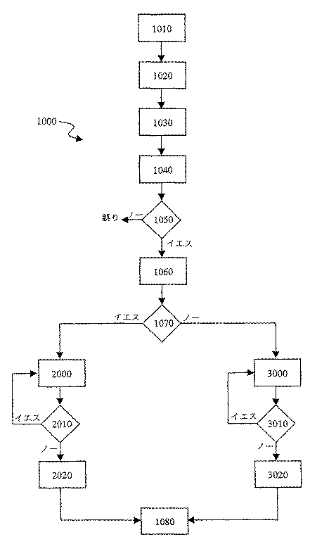
図5には、最適なアイドル速度の性能を得るため、燃料の供給マップを較正する目的にて、エンジン100のアイドル性能をトリムすべくエンジン管理システム10を使用する方法1000の一例が図示されている、工程1010において、マップトリム無効スイッチ88はマップトリム+/−スイッチ86a、86bを作動可能な形態とされている。工程1020において、エンジン管理システム10が調節される。この調節1020は、1)スロットルの小さい調節値(例えば、0乃至10%のスロットルの開き度)を作用可能な範囲として特定すると共に、トリム能力を制限するため(例えば、基準制御マップの調節値の+/−20%以内)、マップトリムの限定を確立することと、2)スロットル位置センサ44がエンジン100が作用可能な範囲内で作動していることを表示するセンサ信号を提供する場合、ライト82cが安定的にグローするようにスマートライトの限定を確立することと、3)1つのマップセット、マップトリムの限定、(例えば、データポート110を介して)スマートライトの限定をエンジン制御ユニット20にダウンロードすることとを含むことができる。
【0049】
工程1030において、エンジン100が始動される。工程1040において、運転者はエンジン100のアイドリングを許容し得るようにスロットルを解放する。工程1050において、エンジン制御ユニット20は、スロットル位置センサ44から供給されたセンサ信号に基づいて、エンジン状態がマップトリムの限定による作動可能な範囲内にあるかどうかを決定する。工程1050の決定が否(即ち、「ノー」)であるならば、エンジン制御ユニット20は、スマートライト82cを点灯させる情報信号をディスプレイ装置82に提供しない。工程1050の決定が肯(即ち、「イエス」)であるならば、エンジン制御ユニット20はスマートライト82を点灯させ、これにより運転者にエンジン100を較正するためトリム+/−スイッチ86a、86b及びトリム無効スイッチ88の操作が有効であることを表示する情報信号をディスプレイ装置82に供給する。工程1050での肯の決定後、工程1060において、運転者はトリム+押釦86aを押す。工程1070において、運転者は、ディスプレイ装置82からの助けを受け、又は助けを受けずに、エンジン性能が変化して、エンジン100がより速く回転しているか(即ち、r.p.m.が増加しているか)どうかを決定する。
【0050】
工程1070での肯定的な決定後、工程2000において、運転者は再度、トリム+スイッチ86aを押す。工程2010において、運転者は再度、エンジンの性能が変化して、エンジン100がより速く回転している(即ち、r.p.m.が増加している)かどうかを決定する。工程2010における決定が肯であるならば、工程2000が繰り返される。トリム能力の限界値(例えば、基準制御マップによる調節点の値の基準エンジン制御値に20%を加えたトリム信号)に達する(図示せず)迄、又はエンジン100がより遅く回転する(即ち、r.p.m.が減少する)ようにエンジン性能が変化したと運転者が決定する迄、工程2000は繰り返される。工程2010の決定が否であるならば、運転者はトリム−押釦86bを押して、それ以前のエンジン性能に戻る。
【0051】
工程1070での否定的な決定の後、工程3000において、運転者は、トリム−押釦86bを押す。工程3010において、運転者は再度、エンジン性能が変化して、エンジン100がより速く回転している(即ち、r.p.m.が増加している)かどうかを決定する。工程3010の決定が肯であるならば、トリム能力(例えば、基準制御マップによる調節点の基準エンジン制御値から20%差し引いたトリム信号)に達する(図示せず)迄、又はエンジン100がより遅く回転する(即ち、r.p.m.が減少する)ようにエンジン性能が変化したと運転者が決定する迄、工程3000は繰り返される。工程3010の決定が否であるならば、運転者はトリム+押釦86aを押して、それ以前のエンジン性能に戻る。工程1080において、運転者は、エンジン100のアイドル速度性能を最適化する、即ち、マップのトリムの限定に従って作用可能な範囲内に調節することに成功している。
【0052】
基準制御マップと比較して、エンジン100をトリミングする効果を評価するため、ABAB性能を行うようにマップトリム無効スイッチ88を操作することができる。運転者が選んだトリム制御値を編集したものをトリム制御マップに記憶させ且つ基準マップセットを修正し得るようにパーソナルコンピュータにアップロードし、これによりその後に使用可能な新たな基準マップを作成することができる。
【0053】
このように、エンジン管理システム10は、エンジン100がその所期の環境内で運転されている間に行うことができる調節によってエンジン性能を較正すること、及びこの運転中、調節の有効性を評価するためABAB比較を行うことを可能にすることとを含む、多数の有利な点を提供する。「ABAB」比較は、運転者がトリム無効スイッチ88をその第一の形態と第二の形態との間にて交互に操作することを意味する。トリム無効スイッチ88の第一の形態において、トリム無効信号によりエンジン制御ユニット20は、トリム制御値によって修正された基準エンジン制御値を計算する(即ち、基準制御マップを修正するトリム制御マップを有する)。トリム無効スイッチ88の第二の形態において、トリム無効信号によって、エンジン制御ユニット20は、基準制御値にのみ等しいエンジンの運転制御値を計算する(即ち、基準制御マップを修正するトリム制御マップは無い)。
【0054】
更に、エンジン管理システム10の実施の形態は、1つのキットとして提供し、エンジン制御ユニット20及び点火モジュールが既存の点火システムに置換し、また、燃料供給システム40及び燃料ポンプ50が既存の気化器に置換するようにすることができる。このキットは、既存の配線ルームに置換すべき置換用配線ルーム(図示せず)を更に含むことができる。エンジン管理システム10の別の有利な点は、その機能が汎用的に適用可能な点、即ち、エンジン管理システム10は、車種に特定のものではなく、多分、第二の車に対して要求されるように、エンジン制御ユニット20に追加のルームを加え又はソフトウエアをアップグレードするだけで異なる車の間で主要な構成要素の全てを交換することが可能な点である。
【0055】
エンジン管理システム10の実施の形態は、内燃機関作動による陸上走行車、水上乗物、及び飛行乗物に対し提供することができ、このため、自動二輪車、全荒地用乗物、スノーモービル、ボート、個人用水上乗物及び飛行機を含む。上述した実施の形態は、エンジン管理システムをトリミングする本発明の装置及び方法の例であり、これにより多数の有利な点が実現される。
【0056】
これらの有利な点には、エンジンの所期の環境内での連続的な運転中、エンジンの運転を較正することを許容することを含む。例えば、レース用エンジンの性能は、エンジンを停止させ且つピットに入ることなく、レース中に較正することができる。更に、エンジン性能は、特定のユーザの規定したエンジン性能範囲内で修正することができる。これらの有利な点は、また、マップセットを掌サイズコンピュータ120からのダウンロードとしてエンジン制御ユニット20に提供することを許容することも含む。これらのマップセットは、ワールドワイドウェブ(world wide web)又はコンピュータディスクを介することを含む、任意の既知の伝送技術又はプロトコルを介して外部のプロセッサに提供することができる。
【0057】
これらの有利な点は、エンジン100をその所期の環境内で連続的に運転する過程中、エンジンの運転者が容易にアクセス可能であるダッシュパネル80、80´にトリム制御部を設けることを更に含む。例えば、ダッシュパネル80、80´は、自動二輪車のハンドルバー200の左手グリップ部202を握る手の指で容易に操作可能であるように取り付けられた、少なくとも1つのスイッチを備えることができる。トリム制御スイッチは、手袋をしたライダーが触覚的に識別し且つ制御部を操作し易くするため、ダッシュパネル80、80´上に人間工学的に配置することができる。
【0058】
これらの有利な点は、エンジンの運転者がちらっと見るだけで情報を伝達することのできる、1つ又はより多数のディスプレイ装置82をダッシュパネル80、80´上に設けることを更に含む。これらのディスプレイ装置82は、異なる型式の情報(例えば、エンジンの状況、エンジン制御ユニットの状況、トリム状態等)を表わすため、異なるモード(例えば、不点灯、安定的なグロー、ゆっくりと点滅すること、急速に点滅すること等)を使用することのできる、「スマートな」即ち画成可能な作用を果たす複数のライト82a、82b、82cを含むことができる。これらのスマートライト82a、82b、82cを作動させるための限定は、マップセットがエンジン制御ユニット20にダウンロードされると同時に、エンジン制御ユニット20にダウンロードさせることができる。
【0059】
特定の実施の形態に関して本発明を開示したが、特許請求の範囲に規定された本発明の範囲から逸脱せずに、説明した実施の形態に対する多数の改変例、変更及び変化を加えることが可能である。従って、本発明は、説明した実施の形態にのみ限定されるものではなく、特許請求の範囲の文言により規定される、全範囲及びその等価物を含むことを意図するものである。
【図面の簡単な説明】
【図1】 エンジンの運転状態を較正するシステムの1つの実施の形態の概略図である。
【図2】 第一の実施の形態のダッシュパネルの平面図である。
【図3】 第二の実施の形態の格納した掌サイズコンピュータを備えるダッシュパネルの平面図である。
【図4】 掌サイズコンピュータを取り外した形態にて図示する図3のダッシュパネルの斜視図である。
【図5】 エンジンの運転状態を較正するエンジン管理ツールの1つの実施の形態に従ってエンジンの性能を較正する方法を示すフロー図である。[0001]
[Cross-reference of pending applications]
This application is a benefit of earlier filing date of US Provisional Patent Application No. 60 / 183,380, filed February 18, 2000, which is hereby incorporated by reference in its entirety. Is an insistence.
[0002]
Field of the Invention
The present disclosure relates to an engine management system for an internal combustion engine. In particular, this disclosure discloses that the driver communicates engine management data between a palm-size computer and an engine control system, and transmits an engine management file between the palm-size computer and an external computer. The object is to provide a system that allows transmission. As an example, a system according to one embodiment changes a trim control value that represents a correction to a reference engine control value based on the engine's control map when the engine is not running or is running within its intended environment. Allows the driver to calibrate the operating state of the engine. More specifically, a recreational vehicle rider can generate a trim control map that calibrates the reference engine control map, for example, for ignition timing and fuel delivery, while driving or driving the vehicle. .
[0003]
The performance of an internal combustion engine includes the operating cycle (eg, 2 cycles, 4 cycles, Otto, Diesel or Wankel), number and design of combustion chambers, selection and control of ignition and fuel delivery systems, ambient conditions when the engine is operating It is believed to depend on a number of factors.
[0004]
Examples of combustion chamber design choices may include choosing a compression ratio and choosing the number of intake and exhaust valves associated with each of the combustion chambers. In general, these selections may not be changed after the engine is manufactured so that the operating conditions of the engine can be calibrated.
[0005]
Regarding ignition systems, breaker point systems and electronic ignition systems are known. These known systems are believed to provide ignition timing based on engine operating characteristics such as, for example, rotational speed and load. In the case of a breaker point system, engine speed is often mechanically detected using a weight displaced by centrifugal force, and the vacuum pressure of the intake manifold is commonly used to detect engine load. Conceivable. In the case of an electronic ignition system, the engine speed is generally detected by an angular motion sensor related to the rotation of the crankshaft, and the engine load is often detected by, for example, the output of a throttle position sensor. It is done. In each of those cases, the ignition timing is believed to be constant according to these known systems for a given operating condition of the engine.
[0006]
With respect to fuel supply systems, carburetors and fuel injection systems are known. These known systems are believed to deliver a quantity of fuel, for example gasoline, based on the amount of air to be introduced into the engine, i.e. according to the throttle position set by the driver. In the case of a carburetor, the fuel would be supplied by an orifice system known as a “jet”. As an example of the action of the carburetor, the idle jet can supply fuel downstream of the throttle valve at the engine idling speed, and the fuel supply amount can be increased by an accelerator pump in order to easily increase the engine speed. It is thought that it can increase. To correct the fuel supply, most carburetors must be disassembled and jets or pumps of different dimensions must be installed. However, this is a laborious process that is thought to be possible in most cases only when the engine is not running.
[0007]
Known fuel injection systems that are electronically operable are believed to spray a precisely regulated amount of fuel into the intake system or directly into the combustion cylinder. It is believed that the amount of fuel is determined by the controller based on engine conditions and based on a data table known as a “map” or “search table”. The map is a set of possible values or “adjustment points” for each of at least one independent variable (ie characteristics of the engine condition) that can be measured by sensors connected to the controller, eg And a corresponding set of control values for an independent variable control function, such as the amount of fuel.
[0008]
Traditionally, maps are considered developed by engine manufacturers and set permanently in the engine control unit at the factory. Currently, in the case of road vehicles, this is believed to be required by law to comply with emissions volume rules. However, even when not required by law, manufacturers have prevented the map from being modified for a variety of reasons, including the fact that the manufacturer has the best engine performance. The manufacturer is worried that the engine operator may damage the engine by setting an inappropriate control value, or the manufacturer This is because we think that we will not have enough skills to correct the problem properly. However, the manufacturer considers that the map is “optimized” to work best under a set of conditions set by the manufacturer. In most cases, these conditions are considered incompatible with the conditions when the engine is operated. As a result, off-the-shelf maps are likely to limit, rather than optimize engine performance.
[0009]
It is further conceivable that ambient conditions such as air temperature, altitude and atmospheric pressure affect the performance of the engine. These conditions are generally considered to greatly affect the entire operating range of the engine. In the case of fuel injection, it is considered known to compensate for these conditions by calculating the adjustments for each operating condition of the engine.
[0010]
Thus, engine performance is believed to be substantially dependent on the method of combustion under ambient conditions. The theoretical mixing ratio of air to gasoline is 14.7: 1. However, it burns at ratios in the range of about 10: 1 to about 20: 1 and also achieves specific engine performance (eg, specific levels of power output, better fuel economy, or reduced emissions) It is often considered desirable to adjust the air-fuel ratio so that it can. Similarly, in order to achieve a specific engine performance (eg minimum fuel consumption or reduced emissions) before the piston reaches the top dead center of the compression stroke, it is generally measured by the degree of crank rotation. It may also be desirable to adjust the ignition timing.
[0011]
For known ignition timing systems and fuel delivery systems, it is considered a disadvantage that the operating conditions of the engine are constrained by certain control conditions set by the suppliers of these systems. Also, in order to make any possible adjustments to these known systems, a technician changes the form of one or more system components or disassembles the system, installs alternative components and installs the system. The need to reassemble is also considered a disadvantage. For this reason, one disadvantage is that for these known systems, the effect and sufficiency of these adjustments cannot be determined while the engine is continuously operating in its intended environment. It is further considered that there is. The inability to directly compare the effects of these adjustments is further considered to be one disadvantage of these known systems. There appears to be a need to overcome these disadvantages of known ignition and fuel delivery systems.
[0012]
SUMMARY OF THE INVENTION
The present invention provides an engine management system for an internal combustion engine. The engine management system includes an engine control system that calculates an engine operation control value, a palm size computer that is movable with respect to the engine control system, and an external computer that communicates with the palm size computer. The engine operation control value can be supplied to the internal combustion engine to change the engine performance. The palm size computer has dimensions of about 15.24 cm height, about 10.16 cm width, and about 2.54 cm thickness. The palm size computer operates a set of engine management tools that communicate engine management data to the engine control system. The external computer downloads to the engine management tool and engine management file of the palm size computer, and uploads from the engine management file of the palm size computer.
[0013]
The accompanying drawings, which are incorporated in and constitute a part of this specification, include one or more embodiments of the invention and, together with the general description above and the following detailed description, implement the invention. It serves to disclose the principles of the invention in accordance with the best mode intended.
[0014]
DETAILED DESCRIPTION OF THE INVENTION
When used in connection with the present invention, the expressions “trim” or “trim” “group” “definition of map trim” and “map set” have specific meanings. The expressions “trim” and “trimming” mean changing the value of one or more adjustment points. The value of this change, which can be positive or negative, can be a function of the original adjustment point or a selected incremental amount. The expression “group” is intended to mean a set of adjustment points or a comprehensive part that are affected by a trimming action.
[0015]
One group can be defined by “map trim restrictions”. For example, map trim limitations include an engine control map that can form a group of adjustment points that fall within a selected range of independent variables such as, for example, sensed engine operating characteristics. Can do. The expression “map set” is intended to mean a single engine control map or a combination of multiple related engine control maps. For example, one map set may consist only of the ignition timing map. Alternatively, one map set may include an ignition timing map and a fuel supply map.
[0016]
Referring to FIG. 1, the engine management system 10 includes an engine management file library in an
[0017]
The housing 20a and other components of the
[0018]
The
[0019]
According to one embodiment, the
[0020]
The
[0021]
The actuator cam can be connected via a slot cable (not shown) to a throttle control element (not shown) that can be controlled by the driver. As will be described in more detail below, a
[0022]
A precisely adjusted amount of fuel can be sprayed from the inside of the
[0023]
The
[0024]
The
[0025]
An
[0026]
A serviceable fuel filter (not shown) can be a separate unit located at any location along the fuel supply, or fuel tank 60,
[0027]
With further reference to FIGS. 2-4, the
[0028]
When the trim disable
[0029]
The
[0030]
3 and 4 illustrate one alternative arrangement of the dash panel 80 '. As best illustrated in FIG. 4, the dash panel 80 'comprises a fixed
[0031]
Next, functions and relationships of system components will be described with reference to all the drawings. As the engine management system 10 shown in the drawing, the
[0032]
Table 1 shows an example of a map that includes an arbitrarily selected number of ignition timing adjustment points. Each of the adjustment points corresponds to two engine operating characteristics: the engine speed value and the throttle position set value. Thus, for a predetermined engine speed value (for example, a value detected by an output signal from the crankshaft
[0033]
[0034]
Engine management data, including one or more map sets, can be engine controlled from the
[0035]
As used herein, the expression “palm size computer” means a handheld device encased within a housing that fits within a normal driver's normal size palm. The height, width, and thickness dimensions of a palm size computer are about 15.24 cm x about 10.16 cm x about 2.54 cm (about 6 inches x about 4 inches x about 1 inch) or less. For this reason, the palm-sized computer can be easily carried in a pocket of a normal size skirt, for example.
[0036]
A battery-operated palm-sized computer as a whole has a touch screen as an input / output device. Examples of such palm-sized computers include the Hewlett-Packard Pocket PC and the 3 Com Palm Palm Pilot.
[0037]
The inventors have discovered a number of unexpected results that are realized by using a
[0038]
The set of engine management tools can include calibration tools such as OPT Cal software manufactured by Optimum Power Technology. Using the OPT Cal software, the engine operator can determine which map set is to be activated for the
[0039]
In addition to processing the downloaded data, the
[0040]
Using the engine management system 10 in conjunction with a
[0041]
In addition, a voltage sensor (not shown) in the electrical system can measure changes that directly affect the response time and accuracy of the electromechanical operation within the
[0042]
The
[0043]
The possible combinations of map sets that can be selected are quite large. As a first example, the center position of the map set
[0044]
The map trim +/-
[0045]
The map trim disable
[0046]
As shown in FIG. 2, the
[0047]
The
[0048]
FIG. 5 illustrates an
[0049]
In
[0050]
After an affirmative determination at
[0051]
After a negative determination at
[0052]
In order to evaluate the effect of trimming
[0053]
In this way, the engine management system 10 calibrates engine performance with adjustments that can be made while the
[0054]
Furthermore, the embodiment of the engine management system 10 is provided as a kit, the
[0055]
Embodiments of the engine management system 10 can be provided for land vehicles, water vehicles, and flying vehicles operated by an internal combustion engine, such as motorcycles, all-terrain vehicles, snowmobiles, boats, personal water. Includes upper vehicles and airplanes. The embodiments described above are examples of the apparatus and method of the present invention for trimming an engine management system, which provides a number of advantages.
[0056]
These advantages include allowing the operation of the engine to be calibrated during continuous operation within the engine's intended environment. For example, the performance of a racing engine can be calibrated during a race without stopping the engine and entering the pit. Furthermore, the engine performance can be modified within the engine performance range defined by the particular user. These advantages also include allowing the map set to be provided to the
[0057]
These advantages include providing trim controls on the
[0058]
These advantages further include providing one or
[0059]
While the invention has been disclosed in terms of specific embodiments, numerous modifications, changes and variations to the described embodiments can be made without departing from the scope of the invention as defined in the claims. It is. Accordingly, the present invention is not intended to be limited to the embodiments described but is intended to include the full scope and equivalents defined by the language of the claims.
[Brief description of the drawings]
FIG. 1 is a schematic diagram of one embodiment of a system for calibrating engine operating conditions.
FIG. 2 is a plan view of the dash panel of the first embodiment.
FIG. 3 is a plan view of a dash panel including a stored palm size computer according to the second embodiment.
4 is a perspective view of the dash panel of FIG. 3 illustrated with the palm size computer removed.
FIG. 5 is a flow diagram illustrating a method for calibrating engine performance in accordance with one embodiment of an engine management tool for calibrating engine operating conditions.
Claims (20)
エンジン性能を変化させるべく内燃機関へ供給されるようにされたエンジンの運転制御値を計算するエンジン制御システム(20)と、
エンジン制御システムに対して移動可能な掌サイズコンピュータ(120)であって、高さ約15.24cm以下、幅約10.16cm以下、厚さ約2.54cm以下の寸法を有し、エンジン管理データをエンジン制御システムに伝達すべく1組のエンジン管理ツール(80)を作動させる掌サイズコンピュータと、
掌サイズコンピュータと連絡する外部コンピュータ(130)と、を備え、
エンジン制御システム(20)は、車のシャシに電気的に接地されたハウジング(20a)を有し、且つ燃料供給モジュール(40)に電気的に接続され、
外部コンピュータ(130)は、掌サイズコンピュータ(120)へエンジン管理ファイルをダウンロードし且つ掌サイズコンピュータからエンジン管理ファイルをアップロードし、
掌サイズコンピュータ(120)は、入力/出力装置としてタッチスクリーンを有しており、
外部コンピュータ(130)は、エンジン管理ファイルのライブラリを含み、
前記エンジン管理ファイルは、掌サイズコンピュータを介してエンジン制御システムに利用可能であり且つエンジン性能を校正するために使用することができることを特徴とするエンジン管理システム。In an engine management system (10) for an internal combustion engine,
An engine control system (20) for calculating an operational control value of an engine adapted to be supplied to the internal combustion engine to change the engine performance;
A palm-sized computer (120) movable with respect to the engine control system, having a height of about 15.24 cm or less, a width of about 10.16 cm or less, and a thickness of about 2.54 cm or less, engine management data A palm size computer that activates a set of engine management tools (80) to communicate to the engine control system;
An external computer (130) in communication with the palm-sized computer,
The engine control system (20) has a housing (20a) that is electrically grounded to the vehicle chassis and is electrically connected to the fuel supply module (40),
The external computer (130) downloads the engine management file to the palm size computer (120) and uploads the engine management file from the palm size computer,
The palm size computer (120) has a touch screen as an input / output device,
The external computer (130) includes a library of engine management files,
The engine management file is available to an engine control system via a palm size computer and can be used to calibrate engine performance .
エンジンの運転の特徴を制御し得るようにエンジンに供給されるエンジンの作動制御値を決定するエンジン制御システム(20)と、
エンジン管理データをエンジン制御システム(20)に連絡する掌サイズコンピュータ(120)と、
エンジン管理データを掌サイズコンピュータ(120)に連絡する外部コンピュータ(130)と、を備え、
エンジン制御システム(20)は、車のシャシに電気的に接地されたハウジング(20a)を有し、且つ燃料供給モジュール(40)に電気的に接続され、
掌サイズコンピュータ(120)は、エンジンの制御システム(20)に接続可能であり、且つ外部コンピュータ(130)に独立的に接続可能であり、更に入力/出力装置としてタッチスクリーンを有しており、
外部コンピュータ(130)は、エンジン管理ファイルのライブラリを含み、
前記エンジン管理ファイルは、掌サイズコンピュータを介してエンジン制御システムに利用可能であり、且つエンジン性能を校正するために使用することができることを特徴とするエンジン管理システム。In the engine management system (10),
An engine control system (20) for determining an engine operating control value supplied to the engine so as to control engine operating characteristics;
A palm size computer (120) for communicating engine management data to the engine control system (20);
An external computer (130) for communicating engine management data to a palm-sized computer (120),
The engine control system (20) has a housing (20a) that is electrically grounded to the vehicle chassis and is electrically connected to the fuel supply module (40),
The palm size computer (120) can be connected to the engine control system (20) and can be independently connected to the external computer (130), and further has a touch screen as an input / output device.
The external computer (130) includes a library of engine management files,
The engine management system can be used for an engine control system through a palm size computer and can be used to calibrate engine performance .
内燃エンジン(100)と、
前記エンジンの1つの運転特徴を制御し得るように前記エンジンに隣接して取り付けられたアクチュエータと、
記憶装置及び出力部を有するエンジン制御システム(20)であって、記憶装置はエンジンの運転制御値を決定する命令を記憶し且つ前記制御値と一致する信号が入力される出力部を有し、出力部は前記アクチュエータに接続される前記エンジン制御システムと、
エンジンの運転制御値を決定するときに使用されるエンジン管理データをエンジン制御システム(20)に連絡する掌サイズコンピュータ(120)と、
前記掌サイズコンピュータを前記エンジン制御システムに接続する第一のカプラー(110)と、
前記エンジン管理データを前記掌サイズコンピュータに連絡する外部コンピュータ(130)と、
前記掌サイズコンピュータ(120)を前記外部コンピュータ(130)に接続する第二のカプラーと、を備え、
エンジン制御システム(20)は、車のシャシに電気的に接地されたハウジング(20a)を有し、且つ燃料供給モジュール(40)に電気的に接続され、
前記掌サイズコンピュータ(120)は、前記エンジン制御システム(20)に接続可能であり、且つ前記外部コンピュータ(130)に独立的に接続可能であり、更に入力/出力装置としてタッチスクリーンを有しており、
外部コンピュータ(130)は、エンジン管理ファイルのライブラリを含み、
前記エンジン管理ファイルは、掌サイズコンピュータを介してエンジン制御システムに利用可能であり、且つエンジン性能を校正するために使用することができるエンジン管理システム。In the engine management system (10),
An internal combustion engine (100);
An actuator mounted adjacent to the engine so as to control one operating characteristic of the engine;
An engine control system (20) having a storage device and an output unit, wherein the storage device stores an instruction for determining an operation control value of the engine and has an output unit to which a signal matching the control value is input, The output unit is connected to the actuator, the engine control system,
A palm-sized computer (120) for communicating engine management data used in determining engine operation control values to the engine control system (20);
A first coupler (110) connecting the palm size computer to the engine control system;
An external computer (130) for communicating the engine management data to the palm-sized computer;
A second coupler connecting the palm size computer (120) to the external computer (130),
The engine control system (20) has a housing (20a) that is electrically grounded to the vehicle chassis and is electrically connected to the fuel supply module (40),
The palm size computer (120) can be connected to the engine control system (20) and can be independently connected to the external computer (130), and further has a touch screen as an input / output device. And
The external computer (130) includes a library of engine management files,
The engine management file is available to an engine control system via a palm size computer and can be used to calibrate engine performance .
1つのマップを外部コンピュータ(130)に記憶させる工程と、
外部コンピュータ(130)を掌サイズコンピュータ(120)に接続する工程と、
マップを外部コンピュータ(130)から掌サイズコンピュータ(120)にダウンロードする工程と、
掌サイズコンピュータ(120)を自動二輪車上に取り付ける工程と、
掌サイズコンピュータ(120)をエンジン制御ユニット(20)に接続する工程と、
マップを掌サイズコンピュータ(120)からエンジン制御ユニット(20)にダウンロードする工程と、を備え、
エンジン制御ユニット(20)は、マップを利用してエンジンの運転値を決定し、
エンジン制御システム(20)は、車のシャシに電気的に接地されたハウジング(20a)を有し、且つ燃料供給モジュール(40)に電気的に接続され、
掌サイズコンピュータ(120)は、入力/出力装置としてタッチスクリーンを有するものであることを特徴とするエンジンを調節する方法。In the method of adjusting the engine,
Storing one map in an external computer (130);
Connecting an external computer (130) to the palm-sized computer (120);
Downloading the map from the external computer (130) to the palm size computer (120);
Mounting a palm size computer (120) on a motorcycle;
Connecting a palm size computer (120) to the engine control unit (20);
Downloading the map from the palm size computer (120) to the engine control unit (20),
The engine control unit (20) determines the engine operating value using the map,
The engine control system (20) has a housing (20a) that is electrically grounded to the vehicle chassis and is electrically connected to the fuel supply module (40),
A method for adjusting an engine, wherein the palm size computer (120) has a touch screen as an input / output device .
Applications Claiming Priority (3)
| Application Number | Priority Date | Filing Date | Title |
|---|---|---|---|
| US18338000P | 2000-02-18 | 2000-02-18 | |
| US60/183,380 | 2000-02-18 | ||
| PCT/US2001/005046 WO2001061176A2 (en) | 2000-02-18 | 2001-02-20 | An engine management system |
Publications (2)
| Publication Number | Publication Date |
|---|---|
| JP2003522900A JP2003522900A (en) | 2003-07-29 |
| JP4043237B2 true JP4043237B2 (en) | 2008-02-06 |
Family
ID=22672565
Family Applications (2)
| Application Number | Title | Priority Date | Filing Date |
|---|---|---|---|
| JP2001560001A Expired - Fee Related JP4043237B2 (en) | 2000-02-18 | 2001-02-20 | Engine management system |
| JP2001560002A Expired - Lifetime JP4017398B2 (en) | 2000-02-18 | 2001-02-20 | Apparatus and method for calibrating an engine management system |
Family Applications After (1)
| Application Number | Title | Priority Date | Filing Date |
|---|---|---|---|
| JP2001560002A Expired - Lifetime JP4017398B2 (en) | 2000-02-18 | 2001-02-20 | Apparatus and method for calibrating an engine management system |
Country Status (10)
| Country | Link |
|---|---|
| US (2) | US6539299B2 (en) |
| EP (2) | EP1255925B1 (en) |
| JP (2) | JP4043237B2 (en) |
| CN (2) | CN100416067C (en) |
| AT (2) | ATE325268T1 (en) |
| AU (4) | AU2001241573B2 (en) |
| CA (2) | CA2398331C (en) |
| DE (2) | DE60119287T2 (en) |
| MX (2) | MXPA02007992A (en) |
| WO (2) | WO2001061177A2 (en) |
Families Citing this family (133)
| Publication number | Priority date | Publication date | Assignee | Title |
|---|---|---|---|---|
| DE19845441C2 (en) * | 1998-10-02 | 2003-01-16 | Ficht Gmbh & Co Kg | Method for electronically trimming an injector |
| US6772061B1 (en) * | 2000-08-18 | 2004-08-03 | Bombardier Recreational Products Inc. | System, method, and apparatus for controlling vehicle performance |
| US7641342B2 (en) * | 2000-10-07 | 2010-01-05 | Metaio Gmbh | Information system and method for providing information using a holographic element |
| US20080161985A1 (en) * | 2001-02-26 | 2008-07-03 | Stefan Hallstensson | Adjusting of the fuel consumption of a water vessel |
| JP4908728B2 (en) * | 2001-04-10 | 2012-04-04 | ローベルト ボツシユ ゲゼルシヤフト ミツト ベシユレンクテル ハフツング | System and method for correcting injection characteristics of at least one injector |
| WO2002103316A2 (en) * | 2001-06-15 | 2002-12-27 | Carcheckup, Llc | Auto diagnosis method and device |
| US6575144B2 (en) * | 2001-07-31 | 2003-06-10 | Ford Motor Company | Method for controlling an engine utilizing vehicle position |
| US20030105577A1 (en) * | 2001-12-05 | 2003-06-05 | Dino Bortolin | Autonomous control of engine operation via a lookup table |
| DE10205375A1 (en) * | 2002-02-09 | 2003-08-21 | Bosch Gmbh Robert | Method and device for controlling an internal combustion engine, in particular for regulating the speed of the internal combustion engine |
| DE10212039A1 (en) * | 2002-03-19 | 2003-10-02 | Zahnradfabrik Friedrichshafen | Wireless communication in vehicles |
| US7280026B2 (en) * | 2002-04-18 | 2007-10-09 | Coldwatt, Inc. | Extended E matrix integrated magnetics (MIM) core |
| US7047128B2 (en) * | 2002-12-12 | 2006-05-16 | Rtk Technologies Limited | Chipped engine control unit system having copy protected and selectable multiple control programs |
| US6925375B2 (en) * | 2003-03-20 | 2005-08-02 | Detroit Diesel Corporation | System and method for determining a parameter set for an engine controller module |
| JP4188227B2 (en) * | 2003-12-26 | 2008-11-26 | 本田技研工業株式会社 | vehicle |
| US20060041337A1 (en) * | 2004-08-19 | 2006-02-23 | Augsburger Brett N | Web-enabled engine reprogramming |
| US7321283B2 (en) * | 2004-08-19 | 2008-01-22 | Coldwatt, Inc. | Vertical winding structures for planar magnetic switched-mode power converters |
| US7427910B2 (en) * | 2004-08-19 | 2008-09-23 | Coldwatt, Inc. | Winding structure for efficient switch-mode power converters |
| DE102004047542A1 (en) * | 2004-09-30 | 2006-04-27 | Bayerische Motoren Werke Ag | Device and method for reading out adaptation values from motor vehicle control units |
| CA2586119C (en) * | 2004-11-12 | 2013-10-01 | Volvo Trucks North America, Inc. | Systems and methods for guiding operators to optimized engine operation |
| US7743606B2 (en) * | 2004-11-18 | 2010-06-29 | Honeywell International Inc. | Exhaust catalyst system |
| US7182075B2 (en) * | 2004-12-07 | 2007-02-27 | Honeywell International Inc. | EGR system |
| US7286928B2 (en) * | 2004-12-22 | 2007-10-23 | Caterpillar Inc. | Wireless communications system for work machine components |
| US7275374B2 (en) * | 2004-12-29 | 2007-10-02 | Honeywell International Inc. | Coordinated multivariable control of fuel and air in engines |
| US7591135B2 (en) * | 2004-12-29 | 2009-09-22 | Honeywell International Inc. | Method and system for using a measure of fueling rate in the air side control of an engine |
| US7328577B2 (en) | 2004-12-29 | 2008-02-12 | Honeywell International Inc. | Multivariable control for an engine |
| US7165399B2 (en) * | 2004-12-29 | 2007-01-23 | Honeywell International Inc. | Method and system for using a measure of fueling rate in the air side control of an engine |
| US7467614B2 (en) * | 2004-12-29 | 2008-12-23 | Honeywell International Inc. | Pedal position and/or pedal change rate for use in control of an engine |
| US20060168945A1 (en) * | 2005-02-02 | 2006-08-03 | Honeywell International Inc. | Aftertreatment for combustion engines |
| US7417875B2 (en) * | 2005-02-08 | 2008-08-26 | Coldwatt, Inc. | Power converter employing integrated magnetics with a current multiplier rectifier and method of operating the same |
| US7385375B2 (en) * | 2005-02-23 | 2008-06-10 | Coldwatt, Inc. | Control circuit for a depletion mode switch and method of operating the same |
| US7876191B2 (en) * | 2005-02-23 | 2011-01-25 | Flextronics International Usa, Inc. | Power converter employing a tapped inductor and integrated magnetics and method of operating the same |
| US7176662B2 (en) * | 2005-02-23 | 2007-02-13 | Coldwatt, Inc. | Power converter employing a tapped inductor and integrated magnetics and method of operating the same |
| US7254477B1 (en) * | 2005-03-17 | 2007-08-07 | Banks Gale C | Apparatus and method for engine performance evaluation |
| US7752840B2 (en) * | 2005-03-24 | 2010-07-13 | Honeywell International Inc. | Engine exhaust heat exchanger |
| GB2424983A (en) | 2005-04-07 | 2006-10-11 | Autoliv Dev | Seatbelt pretensioner control system |
| JP2006315500A (en) * | 2005-05-11 | 2006-11-24 | Yamaha Motor Co Ltd | Saddle riding type vehicle |
| US20090038875A1 (en) * | 2005-05-12 | 2009-02-12 | Arctic Cat, Inc. | Off-road engine configuration with noise reduction system |
| US7469177B2 (en) * | 2005-06-17 | 2008-12-23 | Honeywell International Inc. | Distributed control architecture for powertrains |
| US7389773B2 (en) | 2005-08-18 | 2008-06-24 | Honeywell International Inc. | Emissions sensors for fuel control in engines |
| US7155334B1 (en) | 2005-09-29 | 2006-12-26 | Honeywell International Inc. | Use of sensors in a state observer for a diesel engine |
| US7765792B2 (en) * | 2005-10-21 | 2010-08-03 | Honeywell International Inc. | System for particulate matter sensor signal processing |
| US7357125B2 (en) * | 2005-10-26 | 2008-04-15 | Honeywell International Inc. | Exhaust gas recirculation system |
| US20070144149A1 (en) * | 2005-12-28 | 2007-06-28 | Honeywell International Inc. | Controlled regeneration system |
| US7415389B2 (en) * | 2005-12-29 | 2008-08-19 | Honeywell International Inc. | Calibration of engine control systems |
| US8630768B2 (en) | 2006-05-22 | 2014-01-14 | Inthinc Technology Solutions, Inc. | System and method for monitoring vehicle parameters and driver behavior |
| JP2008019843A (en) * | 2006-07-14 | 2008-01-31 | Yamaha Motor Co Ltd | Engine setting system and server device used for it |
| US8125205B2 (en) * | 2006-08-31 | 2012-02-28 | Flextronics International Usa, Inc. | Power converter employing regulators with a coupled inductor |
| JP2010503577A (en) * | 2006-09-15 | 2010-02-04 | ボルボ ラストバグナー アーベー | Method for ensuring synchronization between an engine control device and a transmission control device, a computer program for executing the method and a computer program product |
| US7899610B2 (en) * | 2006-10-02 | 2011-03-01 | Inthinc Technology Solutions, Inc. | System and method for reconfiguring an electronic control unit of a motor vehicle to optimize fuel economy |
| US7675759B2 (en) | 2006-12-01 | 2010-03-09 | Flextronics International Usa, Inc. | Power system with power converters having an adaptive controller |
| US7667986B2 (en) * | 2006-12-01 | 2010-02-23 | Flextronics International Usa, Inc. | Power system with power converters having an adaptive controller |
| US7675758B2 (en) * | 2006-12-01 | 2010-03-09 | Flextronics International Usa, Inc. | Power converter with an adaptive controller and method of operating the same |
| US7889517B2 (en) * | 2006-12-01 | 2011-02-15 | Flextronics International Usa, Inc. | Power system with power converters having an adaptive controller |
| US9197132B2 (en) | 2006-12-01 | 2015-11-24 | Flextronics International Usa, Inc. | Power converter with an adaptive controller and method of operating the same |
| JP5207431B2 (en) * | 2006-12-21 | 2013-06-12 | ヤマハ発動機株式会社 | Outboard motor fuel control system |
| US8041529B2 (en) * | 2007-02-09 | 2011-10-18 | Robert Bosch Gmbh | Changing parameters in a tested system using virtual working pages |
| US7468649B2 (en) * | 2007-03-14 | 2008-12-23 | Flextronics International Usa, Inc. | Isolated power converter |
| US7906941B2 (en) * | 2007-06-19 | 2011-03-15 | Flextronics International Usa, Inc. | System and method for estimating input power for a power processing circuit |
| US7593808B2 (en) | 2007-08-07 | 2009-09-22 | Banks Gale C | Apparatus and method for engine performance evaluation |
| US8010275B2 (en) * | 2007-10-01 | 2011-08-30 | GM Global Technology Operations LLC | Secured throttle position in a coordinated torque control system |
| US7558663B2 (en) * | 2007-10-03 | 2009-07-07 | Tyler T Drazich | Fuel injection control system with exempt area of fuel map |
| WO2009049076A1 (en) * | 2007-10-09 | 2009-04-16 | Particle Drilling Technologies, Inc. | Injection system and method |
| US8933691B2 (en) * | 2007-10-27 | 2015-01-13 | Walbro Engine Management, L.L.C. | Rotary position sensor |
| CN103122800B (en) * | 2007-10-27 | 2016-01-20 | 沃尔布罗发动机使用有限责任公司 | Engine fuel delivery systems, equipment and method |
| US8612107B2 (en) * | 2008-06-10 | 2013-12-17 | The Regents Of The University Of Michigan | Method, control apparatus and powertrain system controller for real-time, self-learning control based on individual operating style |
| US8060290B2 (en) | 2008-07-17 | 2011-11-15 | Honeywell International Inc. | Configurable automotive controller |
| JP4958867B2 (en) * | 2008-09-19 | 2012-06-20 | 本田技研工業株式会社 | Motorcycle with engine setting system |
| US20100097325A1 (en) * | 2008-10-21 | 2010-04-22 | Daisuke Nagao | Touch screen assemblies and saddle-type vehicles having one or more touch screen assemblies |
| CN102342008B (en) | 2009-01-19 | 2016-08-03 | 伟创力国际美国公司 | Controller for power converter |
| CN102342007B (en) * | 2009-01-19 | 2015-01-07 | 伟创力国际美国公司 | Controller for a power converter |
| WO2010114914A1 (en) * | 2009-03-31 | 2010-10-07 | Flextronics International Usa, Inc. | Magnetic device formed with u-shaped core pieces and power converter employing the same |
| JP2010261385A (en) * | 2009-05-08 | 2010-11-18 | Suzuki Motor Corp | Electronic control throttle valve control apparatus |
| US9077248B2 (en) | 2009-06-17 | 2015-07-07 | Power Systems Technologies Ltd | Start-up circuit for a power adapter |
| US8514593B2 (en) * | 2009-06-17 | 2013-08-20 | Power Systems Technologies, Ltd. | Power converter employing a variable switching frequency and a magnetic device with a non-uniform gap |
| US8643222B2 (en) | 2009-06-17 | 2014-02-04 | Power Systems Technologies Ltd | Power adapter employing a power reducer |
| US20100332077A1 (en) * | 2009-06-26 | 2010-12-30 | Honeywell International Inc. | Wireless winch switch |
| US8224519B2 (en) * | 2009-07-24 | 2012-07-17 | Harley-Davidson Motor Company Group, LLC | Vehicle calibration using data collected during normal operating conditions |
| US8638578B2 (en) | 2009-08-14 | 2014-01-28 | Power System Technologies, Ltd. | Power converter including a charge pump employable in a power adapter |
| US8620461B2 (en) * | 2009-09-24 | 2013-12-31 | Honeywell International, Inc. | Method and system for updating tuning parameters of a controller |
| US8976549B2 (en) * | 2009-12-03 | 2015-03-10 | Power Systems Technologies, Ltd. | Startup circuit including first and second Schmitt triggers and power converter employing the same |
| US8520420B2 (en) * | 2009-12-18 | 2013-08-27 | Power Systems Technologies, Ltd. | Controller for modifying dead time between switches in a power converter |
| US9246391B2 (en) | 2010-01-22 | 2016-01-26 | Power Systems Technologies Ltd. | Controller for providing a corrected signal to a sensed peak current through a circuit element of a power converter |
| US8787043B2 (en) * | 2010-01-22 | 2014-07-22 | Power Systems Technologies, Ltd. | Controller for a power converter and method of operating the same |
| WO2011116225A1 (en) | 2010-03-17 | 2011-09-22 | Power Systems Technologies, Ltd. | Control system for a power converter and method of operating the same |
| WO2011119850A2 (en) * | 2010-03-26 | 2011-09-29 | Power Systems Technologies, Ltd. | Power adapter having a universal serial bus hub |
| WO2011139932A1 (en) * | 2010-05-05 | 2011-11-10 | Ross Richard T | High power to weight two stroke engine and exhaust system |
| US8504175B2 (en) | 2010-06-02 | 2013-08-06 | Honeywell International Inc. | Using model predictive control to optimize variable trajectories and system control |
| US9417884B2 (en) | 2010-11-22 | 2016-08-16 | Freescale Semiconductor, Inc. | Method for enabling calibration during start-up of a micro controller unit and integrated circuit therefor |
| FR2970348A1 (en) * | 2011-01-12 | 2012-07-13 | Peugeot Citroen Automobiles Sa | Actuator controlling method for executing injection function for e.g. diesel engine, in motor vehicle, involves resetting operating point of engine by comparing measured signal and reference signal which is function of operating point |
| US8792257B2 (en) | 2011-03-25 | 2014-07-29 | Power Systems Technologies, Ltd. | Power converter with reduced power dissipation |
| US9677493B2 (en) | 2011-09-19 | 2017-06-13 | Honeywell Spol, S.R.O. | Coordinated engine and emissions control system |
| US20130111905A1 (en) | 2011-11-04 | 2013-05-09 | Honeywell Spol. S.R.O. | Integrated optimization and control of an engine and aftertreatment system |
| US9650934B2 (en) | 2011-11-04 | 2017-05-16 | Honeywell spol.s.r.o. | Engine and aftertreatment optimization system |
| US20130173137A1 (en) * | 2011-12-29 | 2013-07-04 | General Electric Company | System, apparatus, and method for protecting vehicle engines |
| US10495014B2 (en) | 2011-12-29 | 2019-12-03 | Ge Global Sourcing Llc | Systems and methods for displaying test details of an engine control test |
| US8792256B2 (en) | 2012-01-27 | 2014-07-29 | Power Systems Technologies Ltd. | Controller for a switch and method of operating the same |
| JP2014012460A (en) * | 2012-07-04 | 2014-01-23 | Yamaha Motor Co Ltd | Ship propulsion system |
| US9190898B2 (en) | 2012-07-06 | 2015-11-17 | Power Systems Technologies, Ltd | Controller for a power converter and method of operating the same |
| US9379629B2 (en) | 2012-07-16 | 2016-06-28 | Power Systems Technologies, Ltd. | Magnetic device and power converter employing the same |
| US9099232B2 (en) | 2012-07-16 | 2015-08-04 | Power Systems Technologies Ltd. | Magnetic device and power converter employing the same |
| US9106130B2 (en) | 2012-07-16 | 2015-08-11 | Power Systems Technologies, Inc. | Magnetic device and power converter employing the same |
| US9214264B2 (en) | 2012-07-16 | 2015-12-15 | Power Systems Technologies, Ltd. | Magnetic device and power converter employing the same |
| US8589002B1 (en) * | 2012-07-30 | 2013-11-19 | General Electric Company | Methods and systems for estimating engine fuel consumption |
| CN102900556A (en) * | 2012-09-29 | 2013-01-30 | 杭州晟城环保科技有限公司 | Automobile engine working condition adjusting and energy-saving device |
| US9240712B2 (en) | 2012-12-13 | 2016-01-19 | Power Systems Technologies Ltd. | Controller including a common current-sense device for power switches of a power converter |
| US9587576B2 (en) | 2013-03-27 | 2017-03-07 | Ford Global Technologies, Llc | Methods and system for improving vehicle operation |
| CN103287361B (en) * | 2013-06-14 | 2015-05-20 | 力帆实业(集团)股份有限公司 | Independent type engine start and stop control system and control method thereof |
| US9300206B2 (en) | 2013-11-15 | 2016-03-29 | Power Systems Technologies Ltd. | Method for estimating power of a power converter |
| US9278698B2 (en) | 2014-04-23 | 2016-03-08 | Honda Motor Co., Ltd. | Methods and apparatus for limiting engine speed |
| DE102014213185A1 (en) * | 2014-07-08 | 2016-01-14 | Ford Global Technologies, Llc | Apparatus and method for adjusting engine control parameters of an internal combustion engine |
| US10443479B2 (en) * | 2014-10-30 | 2019-10-15 | Roush Enterprises, Inc. | Exhaust control system |
| EP3051367B1 (en) | 2015-01-28 | 2020-11-25 | Honeywell spol s.r.o. | An approach and system for handling constraints for measured disturbances with uncertain preview |
| US9657676B2 (en) * | 2015-02-04 | 2017-05-23 | Ford Global Technologies, Llc | Methods and systems for powertrain control |
| EP3056706A1 (en) | 2015-02-16 | 2016-08-17 | Honeywell International Inc. | An approach for aftertreatment system modeling and model identification |
| EP3091212A1 (en) | 2015-05-06 | 2016-11-09 | Honeywell International Inc. | An identification approach for internal combustion engine mean value models |
| EP3125052B1 (en) | 2015-07-31 | 2020-09-02 | Garrett Transportation I Inc. | Quadratic program solver for mpc using variable ordering |
| US10272779B2 (en) | 2015-08-05 | 2019-04-30 | Garrett Transportation I Inc. | System and approach for dynamic vehicle speed optimization |
| US10082058B2 (en) | 2015-11-02 | 2018-09-25 | Roush Enterprises, Inc. | Muffler with selected exhaust pathways |
| US20170159574A1 (en) * | 2015-12-04 | 2017-06-08 | General Electric Company | Adaptive Engine Model Torque Splitting Optimization |
| US10415492B2 (en) | 2016-01-29 | 2019-09-17 | Garrett Transportation I Inc. | Engine system with inferential sensor |
| USD800739S1 (en) | 2016-02-16 | 2017-10-24 | General Electric Company | Display screen with graphical user interface for displaying test details of an engine control test |
| US10124750B2 (en) | 2016-04-26 | 2018-11-13 | Honeywell International Inc. | Vehicle security module system |
| US10036338B2 (en) | 2016-04-26 | 2018-07-31 | Honeywell International Inc. | Condition-based powertrain control system |
| US9813119B1 (en) | 2016-10-06 | 2017-11-07 | Harley-Davidson Motor Company Group, LLC | Passive wireless accessory switch pack |
| EP3548729B1 (en) | 2016-11-29 | 2023-02-22 | Garrett Transportation I Inc. | An inferential flow sensor |
| US11057213B2 (en) | 2017-10-13 | 2021-07-06 | Garrett Transportation I, Inc. | Authentication system for electronic control unit on a bus |
| JPWO2019187098A1 (en) * | 2018-03-30 | 2021-02-12 | 本田技研工業株式会社 | Internal combustion engine management system, server device, and internal combustion engine management method |
| US11574510B2 (en) | 2020-03-30 | 2023-02-07 | Innova Electronics Corporation | Multi-functional automotive diagnostic tablet with interchangeable function-specific cartridges |
| US11651628B2 (en) | 2020-04-20 | 2023-05-16 | Innova Electronics Corporation | Router for vehicle diagnostic system |
| US11967189B2 (en) | 2020-04-20 | 2024-04-23 | Innova Electronics Corporation | Router for communicating vehicle data to a vehicle resource |
| US11455841B1 (en) | 2021-08-26 | 2022-09-27 | Innova Electronics Corporation | System and method for selective vehicle data retrieval |
| US11335139B1 (en) | 2021-08-26 | 2022-05-17 | Innova Electronics Corporation | System and method for selective vehicle data retrieval |
| US11625962B2 (en) | 2021-08-26 | 2023-04-11 | Innova Electronics Corporation | System, method, and computer program product for providing application-based assistance with vehicle emission test compliance |
Family Cites Families (56)
| Publication number | Priority date | Publication date | Assignee | Title |
|---|---|---|---|---|
| JPS55134732A (en) | 1979-04-04 | 1980-10-20 | Nippon Denso Co Ltd | Optimal controlling method of engine |
| US4321902A (en) * | 1980-04-11 | 1982-03-30 | General Motors Corporation | Engine control method |
| DE3018275A1 (en) | 1980-05-13 | 1981-11-19 | Robert Bosch Gmbh, 7000 Stuttgart | DEVICE FOR OPTIMIZING DATA AND / OR PROGRAMS FOR PROGRAMMED CONTROL UNITS |
| US4408296A (en) | 1980-08-27 | 1983-10-04 | Rca Corporation | Digital timing system for spark advance |
| JPS5813140A (en) | 1981-07-17 | 1983-01-25 | Nissan Motor Co Ltd | Electronic engine control device with external adjustment function |
| US4496286A (en) | 1983-07-18 | 1985-01-29 | J-W Operating Company | Control system for engine-driven compressor unit and method of operation thereof |
| US4703430A (en) | 1983-11-21 | 1987-10-27 | Hitachi, Ltd. | Method controlling air-fuel ratio |
| DE3408215A1 (en) | 1984-02-01 | 1985-08-01 | Robert Bosch Gmbh, 7000 Stuttgart | CONTROL AND REGULATING METHOD FOR THE OPERATING CHARACTERISTICS OF AN INTERNAL COMBUSTION ENGINE |
| DE3407920A1 (en) | 1984-03-03 | 1985-09-05 | Robert Bosch Gmbh, 7000 Stuttgart | ELECTRONIC CONTROL SYSTEM FOR CONTROLLING TECHNICAL PLANTS AND MACHINES AND CONTROL METHODS USING THEM |
| JPH0792018B2 (en) | 1984-07-04 | 1995-10-09 | 日本電装株式会社 | Vehicle control device |
| EP0348449A4 (en) | 1987-11-06 | 1990-02-06 | Invent Eng Pty Ltd | User modifiable fuel injection computer. |
| US5123397A (en) | 1988-07-29 | 1992-06-23 | North American Philips Corporation | Vehicle management computer |
| US5091858A (en) | 1989-01-09 | 1992-02-25 | Digital Fuel Injection | Electronic control of engine fuel delivery |
| CA2057046C (en) * | 1989-06-07 | 1999-06-08 | Edwin Theodore Schoell | Computer-aided engine diagnostic system |
| US4955348A (en) | 1989-11-08 | 1990-09-11 | William A. Budde | Fuel injection conversion system for V-twin motorcycle engines |
| US5523948A (en) | 1990-09-06 | 1996-06-04 | Adrain; John B. | Apparatus and method for modifying control of an originally manufactured engine control module |
| CA2050126A1 (en) | 1990-09-06 | 1992-03-07 | John B. Adrain | Automotive multiple memory selector apparatus with human interactive control |
| US5446665A (en) | 1993-03-18 | 1995-08-29 | John B. Adrain | Automotive multiple memory selector apparatus |
| GB9019423D0 (en) * | 1990-09-06 | 1990-10-24 | Gen Motors Luxembourg Operatio | Electronic controller for vehicle |
| US5200900A (en) | 1990-09-06 | 1993-04-06 | John B. Adrain | Automotive multiple memory selector apparatus with human interactive control |
| WO1992009957A1 (en) | 1990-11-30 | 1992-06-11 | Weber, U.S.A., Inc. | Electronic engine controller having user-variable parameters |
| US5268842A (en) | 1990-12-03 | 1993-12-07 | Cummins Engine Company, Inc. | Electronic control of engine fuel injection based on engine duty cycle |
| US5287281A (en) | 1991-02-27 | 1994-02-15 | Echlin Inc. | Computer controlled flow of nitrous oxide injected into an internal combustion engine |
| US5088464A (en) | 1991-06-24 | 1992-02-18 | Echlin, Inc. | Motorcycle engine management system |
| US5174263A (en) | 1991-06-24 | 1992-12-29 | Echlin, Inc. | Motorcycle engine management system |
| JP3063939B2 (en) | 1992-06-30 | 2000-07-12 | 三信工業株式会社 | Control system for fuel injection engine |
| US5269275A (en) | 1992-11-02 | 1993-12-14 | David Rook | Pulse width modulated controller for nitrous oxide and fuel delivery |
| US5535620A (en) | 1993-04-05 | 1996-07-16 | Applied Computer Engineering, Inc. | Engine management system |
| US5608632A (en) | 1993-10-19 | 1997-03-04 | White; Robert M. | Self-contained sequential-throttle-body-injection engine control system |
| JP2857702B2 (en) | 1993-11-02 | 1999-02-17 | 本田技研工業株式会社 | Fuel injection amount control device for internal combustion engine |
| JPH0828416A (en) | 1994-07-13 | 1996-01-30 | Sanshin Ind Co Ltd | Ignition timing control device for engine |
| JPH0893529A (en) | 1994-09-21 | 1996-04-09 | Honda Motor Co Ltd | Fuel injection controller for internal combustion engine |
| US5701871A (en) | 1994-12-20 | 1997-12-30 | Honda Giken Kogyo Kabushiki Kaisha | Fuel supply control system for internal combustion engines |
| US6098012A (en) | 1995-02-13 | 2000-08-01 | Daimlerchrysler Corporation | Neural network based transient fuel control method |
| US5749346A (en) | 1995-02-23 | 1998-05-12 | Hirel Holdings, Inc. | Electronic control unit for controlling an electronic injector fuel delivery system and method of controlling an electronic injector fuel delivery system |
| US5908463A (en) | 1995-02-25 | 1999-06-01 | Honda Giken Kogyo Kabushiki Kaisha | Fuel metering control system for internal combustion engine |
| US6041279A (en) | 1995-02-25 | 2000-03-21 | Honda Giken Kogyo Kabushiki Kaisha | Fuel metering control system for internal combustion engine |
| US5778857A (en) | 1995-10-02 | 1998-07-14 | Yamaha Hatsudoki Kabushiki Kaisha | Engine control system and method |
| DE19612796A1 (en) | 1996-03-30 | 1997-10-02 | Hans Juergen Hennig | Electronic vehicle, train or aircraft log book |
| JP3139370B2 (en) | 1996-04-23 | 2001-02-26 | トヨタ自動車株式会社 | Ignition timing control device for internal combustion engine |
| US5803043A (en) | 1996-05-29 | 1998-09-08 | Bayron; Harry | Data input interface for power and speed controller |
| US5769051A (en) | 1996-05-29 | 1998-06-23 | Bayron; Harry | Data input interface for power and speed controller |
| US6021369A (en) | 1996-06-27 | 2000-02-01 | Yamaha Hatsudoki Kabushiki Kaisha | Integrated controlling system |
| US6039012A (en) | 1996-09-18 | 2000-03-21 | Yamaha Hatsudoki Kabushiki Kaisha | Operating control system for 2 cycle direct injection engine |
| JPH10289006A (en) | 1997-04-11 | 1998-10-27 | Yamaha Motor Co Ltd | Method for controlling object to be controlled using artificial emotion |
| JPH10318113A (en) | 1997-05-16 | 1998-12-02 | Sanshin Ind Co Ltd | Operation control device for marine engine |
| US5806013A (en) | 1997-08-29 | 1998-09-08 | Echlin, Inc. | Control of engine fuel delivery using an artificial neural network in parallel with a feed-forward controller |
| US5938716A (en) | 1997-09-08 | 1999-08-17 | Cummins Engine Company, Inc. | System for customizing vehicle engine control computer operation |
| WO1999036839A1 (en) | 1998-01-16 | 1999-07-22 | WILLIAMS, Norman, George | User configurable bimodular engine management computer |
| US6020654A (en) | 1998-03-25 | 2000-02-01 | Lear Automotive Dearborn, Inc. | Auto PC wallet PC faceplate |
| US6067965A (en) | 1998-08-31 | 2000-05-30 | Ford Global Technologies, Inc. | Method and system for determining a quantity of fuel to be injected into an internal combustion engine |
| US6189057B1 (en) * | 1998-09-14 | 2001-02-13 | Chrysler Corporation | Motor vehicle accessory interface for transferring serial data with and supplying DC power to external accessory device |
| US6142123A (en) | 1998-12-14 | 2000-11-07 | Cannondale Corporation | Motorcycle |
| US6170463B1 (en) | 1999-03-05 | 2001-01-09 | Outboard Marine Corporation | Method and apparatus for optimizing engine operation |
| US6169943B1 (en) * | 1999-07-14 | 2001-01-02 | Eaton Corporation | Motor vehicle diagnostic system using hand-held remote control |
| US7068147B2 (en) * | 1999-12-07 | 2006-06-27 | Denso Corporation | Control information rewriting system |
-
2001
- 2001-02-16 US US09/784,336 patent/US6539299B2/en not_active Expired - Fee Related
- 2001-02-20 DE DE60119287T patent/DE60119287T2/en not_active Expired - Lifetime
- 2001-02-20 DE DE60119493T patent/DE60119493T2/en not_active Expired - Lifetime
- 2001-02-20 JP JP2001560001A patent/JP4043237B2/en not_active Expired - Fee Related
- 2001-02-20 CN CNB01805210XA patent/CN100416067C/en not_active Expired - Fee Related
- 2001-02-20 EP EP01912831A patent/EP1255925B1/en not_active Expired - Lifetime
- 2001-02-20 MX MXPA02007992A patent/MXPA02007992A/en active IP Right Grant
- 2001-02-20 CN CNB018052118A patent/CN1237264C/en not_active Expired - Fee Related
- 2001-02-20 MX MXPA02007991A patent/MXPA02007991A/en active IP Right Grant
- 2001-02-20 AU AU2001241573A patent/AU2001241573B2/en not_active Ceased
- 2001-02-20 AU AU4157301A patent/AU4157301A/en active Pending
- 2001-02-20 JP JP2001560002A patent/JP4017398B2/en not_active Expired - Lifetime
- 2001-02-20 AT AT01912831T patent/ATE325268T1/en active
- 2001-02-20 US US09/792,010 patent/US6512974B2/en not_active Expired - Fee Related
- 2001-02-20 EP EP01910836A patent/EP1255924B1/en not_active Expired - Lifetime
- 2001-02-20 WO PCT/US2001/005325 patent/WO2001061177A2/en active IP Right Grant
- 2001-02-20 CA CA2398331A patent/CA2398331C/en not_active Expired - Fee Related
- 2001-02-20 WO PCT/US2001/005046 patent/WO2001061176A2/en active IP Right Grant
- 2001-02-20 AU AU3839901A patent/AU3839901A/en active Pending
- 2001-02-20 AT AT01910836T patent/ATE325946T1/en active
- 2001-02-20 AU AU2001238399A patent/AU2001238399B2/en not_active Ceased
- 2001-02-20 CA CA002398577A patent/CA2398577C/en not_active Expired - Fee Related
Also Published As
Similar Documents
| Publication | Publication Date | Title |
|---|---|---|
| JP4043237B2 (en) | Engine management system | |
| US6701897B2 (en) | Engine fuel delivery management system | |
| AU2002320566A1 (en) | An engine fuel delivery management system | |
| CN101010502A (en) | Predictive engine combustion management | |
| US6415766B1 (en) | Engine idle control system | |
| JPH06213026A (en) | Marine propeller | |
| US4373498A (en) | Exhaust gas recirculation system for internal combustion engine | |
| CN103874839A (en) | Rotational speed control device and rotational speed control method for internal combustion engine | |
| KR0149512B1 (en) | Internal combustion engine air supply system | |
| US7288047B1 (en) | Engine and transmission control system and method for a motorized vehicle | |
| EP1617064A2 (en) | Apparatus and method for calibrating an engine management system | |
| JP2003254106A (en) | Fuel supply system for compressive ignition-type dual fuel engine | |
| JP7399593B2 (en) | Internal combustion engine control device | |
| JP2021121731A (en) | Control device for internal combustion engine | |
| CN101965442A (en) | Controller and control method for internal combustion engine | |
| JP2005273605A (en) | Controller of fuel injection engine | |
| AU5106590A (en) | Internal combustion engine air supply system |
Legal Events
| Date | Code | Title | Description |
|---|---|---|---|
| A131 | Notification of reasons for refusal |
Free format text: JAPANESE INTERMEDIATE CODE: A131 Effective date: 20060105 |
|
| A521 | Request for written amendment filed |
Free format text: JAPANESE INTERMEDIATE CODE: A523 Effective date: 20060405 |
|
| A131 | Notification of reasons for refusal |
Free format text: JAPANESE INTERMEDIATE CODE: A131 Effective date: 20070105 |
|
| A601 | Written request for extension of time |
Free format text: JAPANESE INTERMEDIATE CODE: A601 Effective date: 20070109 |
|
| A602 | Written permission of extension of time |
Free format text: JAPANESE INTERMEDIATE CODE: A602 Effective date: 20070116 |
|
| A521 | Request for written amendment filed |
Free format text: JAPANESE INTERMEDIATE CODE: A523 Effective date: 20070705 |
|
| TRDD | Decision of grant or rejection written | ||
| A01 | Written decision to grant a patent or to grant a registration (utility model) |
Free format text: JAPANESE INTERMEDIATE CODE: A01 Effective date: 20071016 |
|
| A61 | First payment of annual fees (during grant procedure) |
Free format text: JAPANESE INTERMEDIATE CODE: A61 Effective date: 20071113 |
|
| R150 | Certificate of patent or registration of utility model |
Free format text: JAPANESE INTERMEDIATE CODE: R150 |
|
| FPAY | Renewal fee payment (event date is renewal date of database) |
Free format text: PAYMENT UNTIL: 20101122 Year of fee payment: 3 |
|
| FPAY | Renewal fee payment (event date is renewal date of database) |
Free format text: PAYMENT UNTIL: 20101122 Year of fee payment: 3 |
|
| FPAY | Renewal fee payment (event date is renewal date of database) |
Free format text: PAYMENT UNTIL: 20111122 Year of fee payment: 4 |
|
| FPAY | Renewal fee payment (event date is renewal date of database) |
Free format text: PAYMENT UNTIL: 20111122 Year of fee payment: 4 |
|
| FPAY | Renewal fee payment (event date is renewal date of database) |
Free format text: PAYMENT UNTIL: 20121122 Year of fee payment: 5 |
|
| LAPS | Cancellation because of no payment of annual fees |