JP4040636B2 - Process cartridge and electrophotographic image forming apparatus - Google Patents
Process cartridge and electrophotographic image forming apparatus Download PDFInfo
- Publication number
- JP4040636B2 JP4040636B2 JP2005086041A JP2005086041A JP4040636B2 JP 4040636 B2 JP4040636 B2 JP 4040636B2 JP 2005086041 A JP2005086041 A JP 2005086041A JP 2005086041 A JP2005086041 A JP 2005086041A JP 4040636 B2 JP4040636 B2 JP 4040636B2
- Authority
- JP
- Japan
- Prior art keywords
- unit
- drum
- driving force
- photosensitive drum
- main body
- Prior art date
- Legal status (The legal status is an assumption and is not a legal conclusion. Google has not performed a legal analysis and makes no representation as to the accuracy of the status listed.)
- Expired - Fee Related
Links
Images


Classifications
-
- G—PHYSICS
- G03—PHOTOGRAPHY; CINEMATOGRAPHY; ANALOGOUS TECHNIQUES USING WAVES OTHER THAN OPTICAL WAVES; ELECTROGRAPHY; HOLOGRAPHY
- G03G—ELECTROGRAPHY; ELECTROPHOTOGRAPHY; MAGNETOGRAPHY
- G03G21/00—Arrangements not provided for by groups G03G13/00 - G03G19/00, e.g. cleaning, elimination of residual charge
- G03G21/16—Mechanical means for facilitating the maintenance of the apparatus, e.g. modular arrangements
- G03G21/18—Mechanical means for facilitating the maintenance of the apparatus, e.g. modular arrangements using a processing cartridge, whereby the process cartridge comprises at least two image processing means in a single unit
- G03G21/1803—Arrangements or disposition of the complete process cartridge or parts thereof
- G03G21/1817—Arrangements or disposition of the complete process cartridge or parts thereof having a submodular arrangement
- G03G21/1825—Pivotable subunit connection
-
- G—PHYSICS
- G03—PHOTOGRAPHY; CINEMATOGRAPHY; ANALOGOUS TECHNIQUES USING WAVES OTHER THAN OPTICAL WAVES; ELECTROGRAPHY; HOLOGRAPHY
- G03G—ELECTROGRAPHY; ELECTROPHOTOGRAPHY; MAGNETOGRAPHY
- G03G15/00—Apparatus for electrographic processes using a charge pattern
-
- G—PHYSICS
- G03—PHOTOGRAPHY; CINEMATOGRAPHY; ANALOGOUS TECHNIQUES USING WAVES OTHER THAN OPTICAL WAVES; ELECTROGRAPHY; HOLOGRAPHY
- G03G—ELECTROGRAPHY; ELECTROPHOTOGRAPHY; MAGNETOGRAPHY
- G03G21/00—Arrangements not provided for by groups G03G13/00 - G03G19/00, e.g. cleaning, elimination of residual charge
- G03G21/16—Mechanical means for facilitating the maintenance of the apparatus, e.g. modular arrangements
- G03G21/18—Mechanical means for facilitating the maintenance of the apparatus, e.g. modular arrangements using a processing cartridge, whereby the process cartridge comprises at least two image processing means in a single unit
- G03G21/1839—Means for handling the process cartridge in the apparatus body
- G03G21/1842—Means for handling the process cartridge in the apparatus body for guiding and mounting the process cartridge, positioning, alignment, locks
- G03G21/185—Means for handling the process cartridge in the apparatus body for guiding and mounting the process cartridge, positioning, alignment, locks the process cartridge being mounted parallel to the axis of the photosensitive member
-
- G—PHYSICS
- G03—PHOTOGRAPHY; CINEMATOGRAPHY; ANALOGOUS TECHNIQUES USING WAVES OTHER THAN OPTICAL WAVES; ELECTROGRAPHY; HOLOGRAPHY
- G03G—ELECTROGRAPHY; ELECTROPHOTOGRAPHY; MAGNETOGRAPHY
- G03G21/00—Arrangements not provided for by groups G03G13/00 - G03G19/00, e.g. cleaning, elimination of residual charge
- G03G21/16—Mechanical means for facilitating the maintenance of the apparatus, e.g. modular arrangements
- G03G21/18—Mechanical means for facilitating the maintenance of the apparatus, e.g. modular arrangements using a processing cartridge, whereby the process cartridge comprises at least two image processing means in a single unit
- G03G21/1839—Means for handling the process cartridge in the apparatus body
- G03G21/1857—Means for handling the process cartridge in the apparatus body for transmitting mechanical drive power to the process cartridge, drive mechanisms, gears, couplings, braking mechanisms
-
- G—PHYSICS
- G03—PHOTOGRAPHY; CINEMATOGRAPHY; ANALOGOUS TECHNIQUES USING WAVES OTHER THAN OPTICAL WAVES; ELECTROGRAPHY; HOLOGRAPHY
- G03G—ELECTROGRAPHY; ELECTROPHOTOGRAPHY; MAGNETOGRAPHY
- G03G2221/00—Processes not provided for by group G03G2215/00, e.g. cleaning or residual charge elimination
- G03G2221/16—Mechanical means for facilitating the maintenance of the apparatus, e.g. modular arrangements and complete machine concepts
- G03G2221/18—Cartridge systems
- G03G2221/183—Process cartridge
- G03G2221/1853—Process cartridge having a submodular arrangement
- G03G2221/1861—Rotational subunit connection
Landscapes
- Physics & Mathematics (AREA)
- General Physics & Mathematics (AREA)
- Engineering & Computer Science (AREA)
- Computer Vision & Pattern Recognition (AREA)
- Electrophotography Configuration And Component (AREA)
- Dry Development In Electrophotography (AREA)
Description
本発明は、電子写真画像形成装置の装置本体に着脱可能なプロセスカートリッジ、及び、前記電子写真画像形成装置に関するものである。 The present invention relates to a process cartridge that can be attached to and detached from an apparatus main body of an electrophotographic image forming apparatus, and the electrophotographic image forming apparatus.
ここで、前記電子写真画像形成装置とは、電子写真画像形成方式を用いて記録媒体(例えば、普通紙、OHPシート)に画像を形成するものである。そして、前記電子写真画像形成装置の例とひいては、例えば、電子写真複写機、電子写真プリンタ(例えば、レーザービームプリンタ、LEDプリンタ等)、ファクシミリ装置及びワードプロセッサ等が挙げられる。 Here, the electrophotographic image forming apparatus forms an image on a recording medium (for example, plain paper, OHP sheet) using an electrophotographic image forming system. Examples of the electrophotographic image forming apparatus include an electrophotographic copying machine, an electrophotographic printer (for example, a laser beam printer, an LED printer, etc.), a facsimile apparatus, a word processor, and the like.
電子写真画像形成装置において使用される現像方式の一つに接触現像方式がある。前記接触現像方式とは、現像ローラと感光体ドラムを接触させた状態で、現像剤を用いて前記感光体ドラムに形成された静電潜像を現像する方式のことである。前記接触現像方式においては、前記現像ローラと前記感光体ドラムとを接触させた状態で長時間放置した場合、前記現像ローラが変形するおそれがある。 One of the developing methods used in the electrophotographic image forming apparatus is a contact developing method. The contact development method is a method of developing the electrostatic latent image formed on the photosensitive drum using a developer in a state where the developing roller and the photosensitive drum are in contact with each other. In the contact development method, when the developing roller and the photosensitive drum are in contact with each other for a long time, the developing roller may be deformed.
前記問題点を解決するために、画像形成時以外には現像ローラと感光体ドラムを離隔するための構成が知られている(特許文献1参照)。ここで、前記構成においては、前記現像ローラと前記感光体ドラムとを離隔するためのトリガが電子写真画像形成装置本体に設けられている。また、前記現像ローラと前記感光体ドラムは画像形成ユニットに設けられている。そして、画像形成ユニットは前記装置本体に着脱可能である。また、前記画像形成ユニットは、前記現像ローラを回転可能に支持する現像ユニットと、前記感光体ドラムを回転可能に支持するドラムユニットとを有している。そして、前記画像形成ユニットが前記装置本体に装着された状態において、画像形成時以外には、前記トリガが前記現像ユニットを押圧する。これによって、前記現像ユニットが前記ドラムユニットに対して移動する。その結果、前記現像ローラと前記感光体ドラムとが離隔する。
しかしながら、前記構成においては、前記トリガが前記装置本体に設けられている。そのため、前記画像形成ユニットが前記装置本体に装着された状態で、前記トリガと前記現像ユニットとの位置精度を考慮する必要がある。 However, in the said structure, the said trigger is provided in the said apparatus main body. Therefore, it is necessary to consider the positional accuracy between the trigger and the developing unit in a state where the image forming unit is mounted on the apparatus main body.
そこで、本発明の目的は、プロセスカートリッジが電子写真画像形成装置本体に装着された状態で現像ユニットを移動させるために移動する移動部材と前記現像ユニットとの間の位置精度を向上させることのできるプロセスカートリッジ、及び、電子写真画像形成装置を提供することにある。 SUMMARY OF THE INVENTION Accordingly, an object of the present invention is to improve the positional accuracy between a moving member that moves to move the developing unit while the process cartridge is mounted on the electrophotographic image forming apparatus main body and the developing unit. A process cartridge and an electrophotographic image forming apparatus are provided.
また、本発明の他の目的は、電子写真画像形成装置本体に装着する際の負荷が軽いプロセスカートリッジ、及び、前記電子写真画像形成装置を提供することにある。 Another object of the present invention is to provide a process cartridge that is lightly loaded when mounted on the electrophotographic image forming apparatus main body, and the electrophotographic image forming apparatus.
また、本発明の他の目的は、現像ローラと電子写真感光体ドラムとが接触する接触位置と前記現像ローラと前記電子写真感光体ドラムとが離隔する離隔位置との間で現像ユニットを移動させるために移動する移動部材と、前記移動部材を駆動させるための駆動力を電子写真画像形成装置本体から受ける移動部材駆動力受け部と、を有するプロセスカートリッジ、及び、前記電子写真画像形成装置を提供することにある。 Another object of the present invention is to move the developing unit between a contact position where the developing roller and the electrophotographic photosensitive drum are in contact with each other and a separation position where the developing roller and the electrophotographic photosensitive drum are separated from each other. Provided are a process cartridge having a moving member that moves for movement, and a moving member driving force receiving portion that receives a driving force for driving the moving member from an electrophotographic image forming apparatus main body, and the electrophotographic image forming apparatus There is to do.
前記課題を解決するために本出願に係る代表的な発明は、
回転可能なドラム駆動力伝達部と、回転可能な本体カップリング部と、を有する電子写真画像形成装置本体に着脱可能なプロセスカートリッジにおいて、
電子写真感光体ドラムと、
前記電子写真感光体ドラムと接触して、現像剤を用いて前記電子写真感光体ドラムに形成された静電潜像を現像するための現像ローラと、
前記電子写真感光体ドラムを支持するドラムユニットであって、前記プロセスカートリッジが前記装置本体に装着された状態で、前記装置本体に位置決めされるドラムユニットと、
前記現像ローラを支持して、前記ドラムユニットに対して移動可能な現像ユニットであって、前記静電潜像を現像するために前記電子写真感光体ドラムと前記現像ローラとを接触させる接触位置と、前記電子写真感光体ドラムと前記現像ローラとを離隔させる離隔位置と、をとり得る現像ユニットと、
前記ドラムユニットが前記装置本体に位置決めされた状態で、前記ドラム駆動力伝達部と嵌合して前記ドラム駆動力伝達部からドラム駆動力を受けることにより前記電子写真感光体ドラムを回転させるドラム駆動力受け部であって、前記ドラムユニットに設けられたドラム駆動力受け部と、
前記ドラムユニットが前記装置本体に位置決めされた状態で、前記本体カップリング部と嵌合して前記本体カップリング部から回転駆動力を受けるカートリッジカップリング部であって、前記ドラムユニットに設けられたカートリッジカップリング部と、
前記カートリッジカップリング部から前記回転駆動力を受けて前記現像ユニットに対して移動することにより、前記現像ユニットを前記接触位置と前記離隔位置との間で移動させる移動部材と、
を有することを特徴とする。
In order to solve the above problems, a representative invention according to the present application is:
In a process cartridge that is attachable to and detachable from an electrophotographic image forming apparatus main body having a rotatable drum driving force transmission portion and a rotatable main body coupling portion ,
An electrophotographic photosensitive drum;
A developing roller for contacting the electrophotographic photosensitive drum and developing an electrostatic latent image formed on the electrophotographic photosensitive drum using a developer;
A drum unit for supporting the electrophotographic photosensitive drum, the drum unit being positioned on the apparatus main body in a state where the process cartridge is mounted on the apparatus main body;
A developing unit that supports the developing roller and is movable with respect to the drum unit, wherein the electrophotographic photosensitive drum and the developing roller are brought into contact with each other to develop the electrostatic latent image; A developing unit capable of taking a separation position for separating the electrophotographic photosensitive drum and the developing roller;
A drum driving force for rotating the electrophotographic photosensitive drum by fitting the drum unit with the drum driving force transmitting portion and receiving the drum driving force from the drum driving force transmitting portion while the drum unit is positioned on the apparatus main body. A drum driving force receiving portion provided in the drum unit;
A cartridge coupling part that is fitted to the main body coupling part and receives a rotational driving force from the main body coupling part in a state where the drum unit is positioned on the apparatus main body, the cartridge cup provided in the drum unit The ring part,
A moving member that moves the developing unit between the contact position and the separation position by receiving the rotational driving force from the cartridge coupling unit and moving the developing unit;
It is characterized by having.
本発明によれば、プロセスカートリッジが電子写真画像形成装置本体に装着された状態で現像ユニットを移動させるために移動する移動部材と前記現像ユニットとの間の位置精度を向上させることができる。 According to the present invention, the positional accuracy between the developing unit and the moving member that moves to move the developing unit in a state where the process cartridge is mounted on the electrophotographic image forming apparatus main body can be improved.
また、本発明によれば、プロセスカートリッジを電子写真画像形成装置本体に装着する際の負荷を軽くすることができる。 Further, according to the present invention, it is possible to reduce the load when the process cartridge is mounted on the electrophotographic image forming apparatus main body.
(電子写真画像形成装置の構成)
まず、図1を用いて、本発明の一実施例であるプロセスカートリッジ7(7Y、7M、7C、7Bk)を着脱可能な電子写真画像形成装置100の構成について説明する。前記画像形成装置100の装置本体99は、前記カートリッジ7(7Y、7M、7C、7Bk)を取り外し可能に装着するために、4つのカートリッジ装着部101を有する。前記各装着部101は、前記装置本体99を設置した状態で、水平方向に並設されている。そして、前記各カートリッジ7(7Y、7M、7C、7Bk)は、それぞれ1個の電子写真感光体ドラム1を有する。ここで、前記カートリッジ7Yはイエローの現像剤を収納している。そして、そして、前記カートリッジ7Mはマゼンタの現像剤を収納している。そして、前記カートリッジ7Cはシアンの現像剤を収納している。そして、前記カートリッジ7Bkは、ブラックの現像剤を収納している。本実施例では、前記現像剤は非磁性一成分トナーである。ここで、前記カートリッジ7は、画像形成方向(図1中の矢印Aで示す方向、即ち、後述する転写ベルト103の移動方向である)において上流側から下流側へ向かって、7Y、7M、7C、7Kの順序で並んでいる。前記感光体ドラム1は、前記装置本体99に設けられた駆動伝達部120によって、時計回りに回転する(図1、図3参照)。前記感光体ドラム1の周囲には、前記回転方向に従って順に、帯電ローラ2、スキャナユニット102、現像ユニット4、転写ベルト103が配置されている。ここで、前記帯電ローラ2は、前記感光体ドラム1に接触した状態で前記感光体ドラム1の周面を均一に帯電する。また、前記スキャナユニット102は、画像情報に基づいてレーザービームLを前記感光体ドラム1の周面に照射する。その結果、前記感光体ドラム1の周面に前記画像情報に応じた静電潜像が形成される。また、前記現像ユニット4は、現像ローラ5を回転可能に支持している。そして、前記現像ローラ5は、現像剤を用いて前記静電潜像を現像する。また、前記転写ベルト103は、前記感光体ドラム1に接触して回転する。そして、前記転写ベルト103には、前記感光体ドラム1に形成された現像剤像が静電転写される。そして、前記クリーニング手段6が、前記転写後の前記感光体ドラム1周面に残った現像剤を除去する。ここで、前記感光体ドラム1、前記帯電ローラ2、前記現像ユニット4、及び、前記クリーニング手段6は一体的にカートリッジ化されて、前記カートリッジ7を構成している。
(Configuration of electrophotographic image forming apparatus)
First, the configuration of an electrophotographic
そして、前記転写ベルト103を間にして前記感光体ドラム1と対向する位置に、1次転写ローラ104が設けられている。ここで、前記1次転写ローラ104は前記転写ベルト103を前記感光体ドラム1に押圧している。また、図1中の右側において、前記転写ベルト103は2次転写ローラ105と対向して接している。そして、記録媒体Sは、前記転写ベルト103と前記2次転写ローラ105とが当接する当接部の間を通過する。前記当接部において、前記転写ベルト103から記録媒体Sへ前記現像剤像が転写される。
A
(画像形成の動作)
画像形成の動作は次の通りである。まず、前記各カートリッジ7の有する前記感光体ドラム1が、前記装置本体99に設けられた駆動伝達部120によって、画像形成のタイミングに合わせて回転する。最初は、前記感光体ドラム1と前記現像ローラ5とは離隔している。しかし、前記画像形成のタイミングにあわせて前記現像ローラ5が回転しながら前記感光体ドラム1と接触する。ここで、フルカラー画像形成を開始する際には、前記現像ローラ5と前記感光体ドラム1との接触動作は、前記カートリッジ7Y、前記カートリッジ7M、前記カートリッジ7C、前記カートリッジ7Bkの順序で行われる。また、フルカラー画像形成を終了する際には、前記現像ローラ5と前記感光体ドラム1との離隔動作も前記順序で行われる。モノクロ画像を形成する際には、画像形成開始時に前記カートリッジ7Bkのみが前記接触及び離隔動作を行う。尚、前記感光体ドラム1と前記現像ローラ5とが離隔及び接触する構成、及び、駆動伝達の詳細については後述する。そして、前記各カートリッジ7に対応するスキャナユニット102が駆動する。そして、前記感光体ドラム1の回転に従動して、前記帯電ローラ2も回転する。その際、前記帯電ローラ2に帯電バイアスが印加される。その結果、前記感光体ドラム1の周面に一様な電荷が付与される。そして前記スキャナユニット102は、画像情報に応じてレーザービームLを前記感光体ドラム1の周面に照射する。その結果、前記感光体ドラム1の周面に静電潜像が形成される。そして、前記現像ユニット4に回転可能に支持された前記現像ローラ5は、現像剤を用いて前記静電潜像を現像する。そして、前記各感光体ドラム1と前記各1次転写ローラ104との間に形成される電界によって、前記各感光体ドラム1に形成された各現像剤像が前記転写ベルト103へ順次転写される。その後、前記転写ベルト103に転写された4色の現像剤像は、前記転写ベルト103と2次転写ローラ105との間に形成される電界によって、記録媒体Sへ転写される。その後、前記記録媒体Sは定着部106に搬送される。そして、前記定着部106において前記現像剤像が前記記録媒体Sに熱定着される。その後、前記記録媒体Sが前記排出部107から前記画像形成装置100の外に排出される。
(Image forming operation)
The image forming operation is as follows. First, the
(プロセスカートリッジの電子写真画像形成装置本体への装着)
次に、図2を用いて、前記カートリッジ7の前記装置本体99への装着について説明する。前記装置本体99の正面には本体カバー108が設けられている。前記本体カバー108の内側には、前記カートリッジ7を装着するためのカートリッジ装着部101が設けられている。そして、前記カートリッジ7は、前記カートリッジ7の長手方向(感光体ドラム1及び現像ローラ5の長手方向と同一方向)に沿って、前記装着部101に装着される。
(Installation of the process cartridge in the main body of the electrophotographic image forming apparatus)
Next, the mounting of the cartridge 7 to the apparatus
(プロセスカートリッジ)
次に、プロセスカートリッジ7について説明する。図3は、前記カートリッジ7の斜視図である。前記カートリッジ7は、ドラムユニット8と現像ユニット2とを有する。前記ドラムユニット8は、感光体ドラム1、帯電ローラ2、及び、クリーニング手段6を有する。尚、前記ドラムユニット8は、前記感光体ドラム1、及び、前記帯電ローラを回転可能に支持する。そして、前記現像ユニット2は、現像ローラ5を回転可能に支持する。前記ドラムユニット8の両端には、前記現像ユニット4を回動可能に支持するための支持部42が設けられている。そして、前記ドラムユニット8は、前記支持部42に設けられた軸11を介して、前記現像ユニット4を揺動可能に支持している。即ち、前記現像ユニット4は、前記ドラムユニット8に対して移動可能である。更に言い換えると、前記現像ユニット4と前記ドラムユニット8とは、前記支持部42を介して回動可能に結合している。また、前記カートリッジ7は、前記ドラムユニット8と前記現像ユニット4との間に付勢力(弾性力)を作用させるための付勢部材としてのバネ12を有する。尚、前記バネ12は、その一端を前記ドラムユニット8に、その他端を前記現像ユニット4に取り付けられている。そして、前記付勢力によって、前記現像ローラ5と前記感光体ドラム1とが接触する。ここで、前記付勢部材の例としてバネを挙げたが、両ユニット間に付勢力を作用させるものであればバネ以外であってもよい。
(Process cartridge)
Next, the process cartridge 7 will be described. FIG. 3 is a perspective view of the cartridge 7. The cartridge 7 has a drum unit 8 and a developing unit 2. The drum unit 8 includes a
また、前記カートリッジ7が前記装置本体99に装着される装着方向において、前記ドラムユニット8の前方にはドラム駆動力受け部9が設けられている。ここで、前記駆動力受け部9は、前記装着方向において、前記ドラムユニット8の枠体81よりも前方に突出している。また、本実施例では、前記駆動力受け部9としてカップリング部材(カートリッジ側カップリング部材)を用いている。そして前記カップリング部材は、断面が複数の角部を有する非円形のねじれた突起である。一方、前記装置本体99には、駆動力伝達部120が設けられている。ここで、本実施例では、前記駆動力伝達部120としてカップリング部材(カートリッジ側カップリング部材)を用いている。そして、前記カップリング部材は、断面が複数の角部を有する非円形のねじれた穴である。ここで、前記カートリッジ7が前記装置本体に装着された状態で、前記駆動力受け部9は、前記感光体ドラム1を回転させるための駆動力を前記駆動力伝達部から受ける。即ち、前記カートリッジ7を前記装置本体99に装着した状態で、前記ねじれた突起と前記ねじれた穴が嵌合することによって、前記駆動力伝達部120から前記駆動力受け部9に駆動力が伝達される。このように本実施例においては、前記カップリング部材同士の係合によって、前記装置本体99から前記感光体ドラム1を回転させるためのドラム駆動力を受ける。ここで、カップリング部材は、前記長手方向において係合するので、前記カートリッジ7を装着する際に妨げとなることはない。
A drum driving force receiving portion 9 is provided in front of the drum unit 8 in the mounting direction in which the cartridge 7 is mounted on the apparatus
また、前記装着方向において前記ドラムユニット8の前方には、移動部材駆動力受け部10が回転可能に設けられている。本実施例では、前記駆動力受け部10としてカップリング機構が用いられている。ここで、前記駆動力受け部10と前記駆動力受け部9とは独立して設けられている。また、前記駆動力受け部10は、前記装着方向において、前記枠体81よりも後方に位置する。言い換えれば、前記駆動力受け部10は、前記枠体81の内部に位置する。更に言い換えれば、前記装着方向において、前記駆動力受け部10は、前記装着方向において、前記駆動力受け部9よりも後方に位置する。これによって、前記駆動力受け部10はより安定して駆動力を受けることができる。また、前記駆動力受け部10は、前記現像ローラ5と前記感光体ドラム1とを接触及び離隔させるように前記現像ユニット4を移動させるための駆動力を前記装置本体99から受ける。ここで、前記駆動力受け部10は、前記装着方向の前方に向かって突き出た突起部10a、10bを有する。前記突起部10a、10bは、前記枠体81の外側に露出している。また、前記駆動力受け部10は、ギア部10cを有している。前記ギア部10cは、前記装着方向において、前記突起部10a,10bよりも後方に位置する。前記ギア部10cは、前記駆動力受け部10が受けた駆動力をカム19(後述する)に伝達する。前記感光体ドラム1と前記現像ローラ5とを接触及び離隔させるための駆動伝達構成については後述する。
A moving member driving
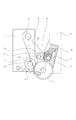
(現像ローラ接触離隔構成)
図4に、前記カートリッジ7を内側から見た図を示す。図4は、前記カートリッジ7の内部の構成が理解し易いように、前記現像ユニット4と前記感光体ドラム1とを一部切断した状態を示す。図4はカートリッジ7の長手方向の一端を示しているが、前記長手方向の他端も同様に構成されている。尚、本実施例では、前記カートリッジ7の構成は、収納している現像剤の色以外は、各色ともに同じである。
(Development roller contact separation structure)
FIG. 4 shows the cartridge 7 viewed from the inside. FIG. 4 shows a state in which the developing unit 4 and the
前記現像ローラ5は金属軸50の周面に弾性体51を被覆したものである。ここで、例えば、前記軸50と前記弾性体51は一体成形したものである。前記弾性体51とひいては、ソリッドゴム単層、又は、ソリッドゴム層に樹脂コーティングを施したものがある。
The developing
そして、円筒形状のコロ13が、前記金属軸50の両端部に回動可能に設けられている。前記コロ13の外径は、前記現像ローラ5の外径よりもわずかに小さい。そして、前記コロ13は画像形成時に前記感光体ドラム1の周面に当接する。これによって、前記感光体ドラム1の前記弾性体51に対する侵入量が所望の値に規制される。
A
また、前記現像ユニット4と前記ドラムユニット8との間には、移動部材としてのカム19が設けられている。具体的には、前記装着方向に沿って見て、前記カム19は、前記現像ローラ5と前記帯電ローラ2との間に設けられている。更に言うと、前記装着方向に沿って見て、前記カム19は、前記現像ローラ5の軸線と、前記帯電ローラ2の軸線と、前記感光体ドラム1の軸線、及び、前記軸11の軸線とで囲まれた領域(図6、図7において一点鎖線によって囲まれた領域R)に設けられている。これによって、前記カム19を配置するためのスペースを新たに設ける必要がなくなる。そのため、前記カートリッジ7の小型化を図ることができる。ひいては、前記装置本体99の小型化を図ることができる。また、軸14が、前記感光体ドラム1と平行に、前記ドラムユニット8に設けられている。前記軸14は、前記ドラムユニット8の長手方向に沿って、前記ドラムユニット8の一端から他端に亘って設けられている。前記カム19(19a、19b)は、前記軸14の長手方向の一端と他端に設けられている(図3参照)。ここで、前記軸14の長手方向の両端は、前記ドラムユニット8の枠体81に回動可能に支持されている。具体的には、前記軸14の長手方向において、前記カム19よりも外側が前記枠体81に支持されている。即ち、前記カム19は、前記長手方向において、前記枠体81の内側に設けられている。このように前記カム19を配置することによって、前記カートリッジ7の小型化を図ることができる。また、前記スキャナユニット102から照射されたレーザービームLは、前記帯電ローラ2と前記軸14との間を通る。ここで、前記カム19は、前記現像ユニット4の長手方向の両端部であって、前記現像ユニット4の側面に各々設けられた被押圧面15と対向している。尚、前記軸14には突起部20が設けられている。前記突起部20は、前記軸14の長手方向において前記カム19よりも中央寄りの位置に位置している。また、前記突起部20は、前記帯電ローラ2と前記感光体ドラム1との接触を解除するためのものである。前記帯電ローラ2の接触解除に関わる構成および作用については後述する。
Further, a
図6は、前記現像ローラ5と前記感光体ドラム1とが前記長手方向に沿って接触している状態を示す。ここで、前記現像ローラ5と前記感光体ドラム1とが前記長手方向に沿って互いに接触している状態において、前記ドラムユニット8に対する前記現像ユニット4の位置を接触位置と言う。また、図7は、前記現像ローラ5と前記感光体ドラム1とが離隔している状態を示す。このように、前記現像ローラ5と前記感光体ドラム1とが互いに離れている状態において、前記ドラムユニット8に対する前記現像ユニット4の位置を離隔位置と言う。前記カム19は大径部191と小径部192を有する。前記大径部191が前記被押圧面15と対向する角度に位置している場合、前記大径部191は前記被押圧面15と接触している。そして、前記大径部191は前記被押圧面15を略水平方向へ押圧する。その際、前記現像ユニット4が前記離隔位置に位置する(図7)。そして、前記現像ローラ5と前記感光体ドラム1とが離隔する。図7において、離隔量をmで表記している。本実施例では離隔量mが1mm程度になるように、前記カム19の形状を設定している。そして、前記装置本体99から前記駆動力受け部10が前記カム19を回転させるための駆動力を受ける。これにより、前記カム19が前記大径部191と前記被押圧面15とが接触した位置から前記バネ12の弾性力に抗して反時計回りに回転する。この際、前記現像ユニット4が、前記バネ12の弾性力によって、軸11を中心として反時計回りに回転する。前記現像ユニット4の回転に従って、前記離隔量は次第に小さくなっていく。そして、前記小径部192が前記被押圧面15と対向する。その結果、前記現像ユニット4が前記離隔位置から前記接触位置に移動する(図6)。この状態では、前記現像ローラ5と前記感光体ドラム1とが接触する。即ち、前記大径部191と前記被押圧面15とが接触した位置から前記カム19が180°回転すると、前記小径部192が前記被押圧面15と対向する。その結果、前記現像ユニット4が前記離隔位置から前記接触位置に移動する。ここで、前記現像ユニット4が前記接触位置に位置する際には、前記カム19は前記被押圧面15から完全に離隔している。まとめると、前記カートリッジ7が前記装置本体99に装着された状態で前記カム19が180°回転する毎に、前記ドラムユニット8に対して前記現像ユニット4が前記接触位置(図6)と前記離隔位置(図7)との間で移動する。即ち、前記カム19は、前記現像ユニット4を前記接触位置と前記離隔位置との間で移動させるために回転する。
FIG. 6 shows a state where the developing
ここで、前記カム19の外周形状は線対称形状である。これによって、前記カム19の回転方向が時計回り又は反時計回りのいずれであっても、同じタイミングで前記現像ローラ5と前記感光体ドラム1との接触及び離隔動作を行うことができる。また、前記カム19の外周形状は滑らかな曲線である。これによって、前記接触及び離隔の衝撃による画像への影響を少なくできる。即ち、両者を接触する際には、前記バネ12の弾性力によって、前記カム19の回転に応じて、前記被押圧面15が前記カム19の曲面に沿って徐々に下方へ移動する。そこで、両者が接触する際の振動を軽減できる。前記カートリッジ7を単体で出荷する場合には、前記大径部191を前記被押圧面15に対向させた状態に前記カム19の位置を維持する。また、被押圧面15が平面形状であるのに対し、前記大径部191の一部も平面形状にしている。そして、前記カートリッジ7を単体で出荷する際には、前記平面同士を接触させて、且つ、前記バネ12の弾性力でもって、前記平面同士を押圧するように前記ユニット4,8を付勢させる。これによって、前記カム19が不用意に回転することを規制できる。そのため、前記カートリッジ7の輸送中に、振動などで前記カム19が回転することを防止できる。これによって、前記カートリッジ7の輸送中に前記現像ローラ4と前記感光体ドラム1とが接触するのを防止できる。また、前記カートリッジ7が前記装置本体99に装着された状態で、前記装置本体99から駆動力の伝達を受けて前記カム19が回転すれば、前記現像ユニットを前記離隔位置から前記接触位置にすることができる。このように、本実施例によれば、前記感光体ドラム1と前記現像ローラ5とを前記長手方向に沿って当接させた状態で長期に保管するときに生じる前記弾性体51の変形を抑制出来る。また、前記カム19が前記カートリッジ7の枠体71の内部に配置されることによって、前記カム19が前記装置本体99に配置される場合と比べて、前記現像ユニット4を前記接触位置と前記離隔位置に移動させる際の前記カム19の変位量を少なくすることができる。また、前述した通り、前記カム19は前記領域R(即ち、前記現像ローラ5及び感光体ドラム1の近く)に配置されている。これにより、前記現像ローラ5と前記感光体ドラム1との間の離隔量を決定する際に、前記枠体71やその他の部品の変形量や公差等による影響を少なくできる。
Here, the outer peripheral shape of the
尚、本実施例においては、移動部材としてカムを例に挙げて説明した。しかし、移動部材としては、カム機構に限定されず、例えばクランク機構等であっても良い。また、移動部材の移動態様としては、回転運動のみならず直線運動も含まれる。尚、本実施例で説明した通り、カムの回転運動の場合には、設置するための空間を小さくすることができる。 In the present embodiment, the cam has been described as an example of the moving member. However, the moving member is not limited to the cam mechanism, and may be a crank mechanism, for example. In addition, the moving mode of the moving member includes not only rotational motion but also linear motion. As described in the present embodiment, in the case of the rotational movement of the cam, the installation space can be reduced.
また、本実施例においては、前記現像ユニット4を前記接触位置から前記離隔位置へ移動させるための力は、前記カム19が前記被押圧部15に付勢する付勢力である。また、前記現像ユニット4を前記離隔位置から前記接触位置へ移動させるための力は、前記バネ12の弾性力である。しかし、前記移動させるための力は、本実施例の形態に限られず、前述した内容と逆であっても良い。まとめると、前記力は、前記移動部材の移動に応じて発生する力のことである。即ち、「移動部材が現像ユニットを接触位置と離隔位置との間で移動させる」構成とは、カムとバネの組み合わせに限定されない。「移動部材の移動に応じて、現像ユニットが接触位置と離隔位置との間で移動させる」ことができる構成ならば良い。例えば、前述したクランク機構等を用いても良い。尚、本実施例のように、前記カム19を用いて前記現像ユニット4を前記離隔位置へ移動させて、前記バネ12を用いて前記現像ユニット4を前記接触位置へ移動させる構成が、前記感光体ドラム1に対する前記現像ローラ5の侵入量を安定させることができる。
In this embodiment, the force for moving the developing unit 4 from the contact position to the separation position is a biasing force that biases the
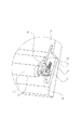
(移動部材の駆動伝達)
図8に、前記装着方向におけるプロセスカートリッジ7の前方の側面図を示す。前記カートリッジ7が前記装置本体99に装着された状態で、前記ドラムユニット8は前記装置本体99に位置決めされる。具体的には、前記装着方向において、前記ドラムユニット8の前方であって前記ドラムユニット8の下側に第一被位置決め部82及び第二被位置決め部83が設けられている。尚、前記装着方向において前記ドラムユニット8の後方に、前記第一被位置決め部82及び前記第二被位置決め部83と同様の被位置決め部(不図示)が設けられている。そして、前記カートリッジ7が前記装着部101に装着された際に、前記装着方向の前方において、前記第一被位置決め部82、前記第二被位置決め部83が前記装置本体99に位置決めされる。
(Drive transmission of moving member)
FIG. 8 shows a front side view of the process cartridge 7 in the mounting direction. In a state where the cartridge 7 is mounted on the apparatus
更に、前記装着方向において、前記ドラムユニット8の前方に、被回転止め部84が設けられている。前記被回転止め部84は、前記装置本体に設けられた回転止め部(不図示)によって、前記ドラムユニット8が前記装着方向に対して交差する交差方向に回転するのを規制される。即ち、前記被回転止め部84は、前記ドラムユニット8が前記駆動力受け部9を中心に回転するのを規制する。そして、前記装着方向において、前記ドラムユニット8の前方には、移動部材駆動力受け部10が回転可能に設けられている。このように、前記装置本体99に位置決めされた前記ドラムユニット8に前記駆動力受け部10を設けることにより、前記現像ユニット4を移動させるための駆動力を安定して受けることができる。更に、前記駆動力受け部9の回転中心を中心として前記回転中心と前記被回転止め部84との最短距離を半径とする円周内に前記駆動力受け部10を配置する。これによって、前記駆動力受け部10が前記駆動力を受ける際の、前記駆動力受け部10の位置を安定させることができる。
Further, a rotation stop portion 84 is provided in front of the drum unit 8 in the mounting direction. The rotation-stopped portion 84 is restricted from rotating in the crossing direction intersecting the mounting direction by the rotation-stopping portion (not shown) provided in the apparatus main body. That is, the rotation-stopped portion 84 restricts the drum unit 8 from rotating around the driving force receiving portion 9. A moving member driving
また、前記装着方向において、前記ドラムユニット8の前方には、移動部材ギア17が回転可能に設けられている。前記ギア17は、前記軸14の長手方向の端部に設けられている。更に、前記ギア17はアイドラギア18を介して前記駆動力受け部10のギア部10cとギア連結している。ここで、前記ギア17と前記ギア部10cの歯数は等しく16歯で構成されている。そうすることで前記ギア部10cの1回転に対し、前記ギア17も等しく1回転する。即ち、前記駆動力受け部10と前記軸14との回転数を1対1に対応させている。そこで、前記ギア17が回転することによって前記軸14が回転する。そして、前記軸14が回転することによって前記カム19が回転する。ここで、前記カム19は、前記軸14の一端と他端とに固定して設けられている。ここで、本実施例では、前記駆動力受け部10としてカップリング(カートリッジカップリング)を用いている。そして、前記カップリングは、前記装着方向の前方に突出した第一突起部10a、第二突起部10bを有する。即ち、前記第一突起部10a及び前記第二突起部10bは、同一半径であって角度の異なる2つの円弧状である。そして、前記第一突起部10a及び前記第二突起部10bは、フォークのように突出している。前記第一突起部10aの円弧角は150°であるのに対して、前記第二突起部10bの円弧角は90°である。
A moving
一方、図9に示すように、前記装置本体99には、前記駆動力受け部10に駆動力を伝達する駆動力伝達部108が設けられている。本実施例では、前記駆動力伝達部108としてカップリング(本体カップリング)を用いている。ここで、前記カートリッジ7が前記装置本体99に装着された状態で、前記伝達部108は、前記駆動力受け部10と対向する。そして、前記伝達部108としての前記カップリングは、同一半径の円弧状である2つの突起部を有している。前記2つの突起部は、フォークのように突出した形状である。前記2つの突起部は、前記駆動力受け部10の第一の突起部10aと第二の突起部10bとの間の凹みの円弧よりもわずかに小さい円弧形状である。そして、前記駆動力受け部10は前記伝達部108に対して、所定の角度でのみ嵌合可能となっている。
On the other hand, as shown in FIG. 9, the apparatus
前記伝達部108の内部にはD字形状の穴部108a(不図示)が設けられている。そして、前記回動軸109には、D字形状の突起部109aが設けられている。前記伝達部108は、前記回動軸109の軸方向にスライド可能に前記回動軸109に対して支持されている。そして、前記回動軸109と同軸に設けられた圧縮バネ110によって、前記伝達部108は、前記カートリッジ7の方向に付勢されている。そして、前記回動軸109の先端には、Eリング111が取り付けられている。そして、前記Eリング111が、前記伝達部108が前記回動軸109から脱落するのを防止している。前記バネ110の付勢力は、前記伝達部108がスライドし得る程度の最小の付勢力に設定している。一方、前記回動軸109の回転方向に対ひいては、前記穴部108aと前記突起部109aとが嵌合することにより、前記伝達部108と前記回動軸109とが一体的に回転する。前記回動軸109は、軸受け部材112を介して、板金113に回転可能に支持されている。ここで、前記軸受け部材112、及び、前記板金113は、前記装置本体99に設けられている。また、前記回動軸109にはギア114が結合しており、前記回動軸109と前記ギア114とが一体的に回転する。前記ギア114はモータ(不図示)とギア連結している。また、前記装置本体99には、前記ギア114の回転角度を0°と180°の2箇所で検知可能なセンサ(不図示)が設けられている。
A D-shaped hole 108 a (not shown) is provided inside the
前記伝達部108と前記駆動力受け部10とのカップリング動作について説明する。前記カートリッジ7を前記装置本体99に装着した際、前記駆動力受け部10と嵌合しない角度に前記伝達部108が位置する場合には、前記回動軸109の軸方向に前記伝達部108が退避する。そして、モータ(不図示)が回転することによって、前記回動軸109と前記伝達部108とが一体となって回転する。前記モータは前記装置本体99に設けられている。そして、前記伝達部108が前記駆動力受け部10と嵌合する角度まで回転した際に、前記バネ110の付勢力によって前記伝達部108が前記駆動力受け部10の方向に移動する。そして、前記伝達部108と前記駆動力受け部10が嵌合が完了する。これによって、前記伝達部108から前記駆動力受け部10に駆動力が伝達される。このように、前記装着方向に沿って前記カートリッジ7を前記装置本体99に装着して前記モータが回転するだけで、前記伝達部108と前記駆動力受け部10が嵌合する。そのため、前記伝達部108と前記駆動力受け部10にギアを用いる場合に比べて、両者を嵌合させるための動作が不要になる。また前記伝達部108と前記駆動力受け部10との駆動構成としてカップリング部材を用いたので、両者が前記長手方向において係合する。そのため、前記カートリッジ7を前記装置本体99に装着する際に妨げとなることはない。
A coupling operation between the
前記伝達部108と前記駆動力受け部10とが所定の角度でのみ嵌合して、前記駆動力受け部10と移動部材14との回転数が1対1に対応している。そのため、前記センサによって、前記移動部材14の角度を検知して、かつ、制御することができる。即ち、前記センサによって、画像形成時には現像ローラ5と感光体ドラム1とを接触させて、画像形成時以外では現像ローラ5と感光体ドラム1とを離隔させるように制御することができる。そうすることによって、現像ローラ5の有する弾性体の永久変形を防止できる。さらに、画像形成時以外では、現像ローラ5を回転停止し回転時間を極力短くできる。そうすることによって、前記カートリッジ7の寿命を延ばすことができる。
The
また、本実施例のように前記カートリッジ7内に、前記現像ローラ5と前記感光体ドラム1とを接触及び離隔するための前記カム19を設けたことによって、前記カム19のためのスペースを前記装置本体99に設ける必要がない。特に、本実施例では、前記カートリッジ7を前記装置本体99へ装着する装着方向は現像ローラ5の長手方向と平行な方向であり、前記現像ユニット4と前記ドラムユニット8との間に前記カム19が設けられている。そのため、前記カートリッジ7の外部に前記現像ユニット4を移動させるための部材を設ける場合と比べてもカートリッジ7を小型化できる。
Further, the
尚、本実施例では、前記感光体ドラム1に駆動力を伝達させる構成、及び、前記カム19に駆動力を伝達させる構成にカップリングを用いたが、これに限定されるものではない。例えば、前記カップリングの代わりにギアを用いても良い。また、前記カートリッジ7を前記装置本体99に装着される装着方向に限定されることはない。即ち、前記カートリッジ7の長手方向と交差する交差方向へ向かって、前記カートリッジ7を前記装置本体99に装着しても良い。しかしながら、前述した構成によれば、前述した効果が得られる。
In the present embodiment, the coupling is used for the structure for transmitting the driving force to the
(帯電ローラ接触解除)
次に、前記帯電ローラ2と前記感光体ドラム1とが接触、及び、その接触を解除する機構について説明する。
(Release charging roller contact)
Next, a contact mechanism between the charging roller 2 and the
まず、図11を用いて、前記帯電ローラ2の軸支持構成について説明する。図10は、前記帯電ローラ2の長手方向端部の斜視図である。なお、本図は前記長手方向の一端のみが示されている。しかし、前記長手方向の他端についても同様の構成である。 First, the shaft support structure of the charging roller 2 will be described with reference to FIG. FIG. 10 is a perspective view of the longitudinal end portion of the charging roller 2. In the figure, only one end in the longitudinal direction is shown. However, the other end in the longitudinal direction has the same configuration.
前記帯電ローラ2は、金属軸2bと弾性体2aとを一体成形したものである。そして、前記金属軸2bの長手方向の一端には、キャップ形状の軸受け部材21が設けられている。そして、前記軸受け部材21が前記金属軸2bを回転可能に支持している。前記軸受け部材21の側面には、前記軸受け部材21をガイドするためのガイド溝210が設けられている。そして、前記ガイド溝210は、前記ドラムユニット8の枠体81に設けられたガイドリブ22に沿って、スライド可能に支持されている。このようにして、前記帯電ローラ2は、前記帯電ローラ2の軸線と前記感光体ドラム1の軸線とを通る平面と平行に移動可能となる。そして、前記枠体81に取り付けられたバネ23が、前記軸受け部材21を前記感光体ドラム1の方向へ付勢する。これによって、前記帯電ローラ2と前記感光体ドラム1とが接触している。
The charging roller 2 is formed by integrally forming a metal shaft 2b and an elastic body 2a. A cap-shaped
以下、前記帯電ローラ2が前記感光体ドラム1と接触して画像形成可能な状態となった前記コマ16の姿勢を第一の姿勢とよぶ。そして、この際の前記感光体ドラム1に対する前記帯電ローラ2の位置を第一位置とよぶ。また、前記帯電ローラ2が前記感光体ドラム1から離隔した状態における前記コマ16の姿勢を第二の姿勢とする。そして、この際の前記感光体ドラム1に対する前記帯電ローラ2の位置を第二位置とよぶ。
Hereinafter, the posture of the top 16 in which the charging roller 2 is in contact with the
前記金属軸2bには、接触解除コマ16(以下単にコマ)が回動可能に支持されている。即ち、前記コマ16は、前記弾性体2aと前記軸受け部材21との間に設けられている。図12に前記コマ16の形状を示す。図12中の破線で示される円は前記帯電ローラ2の外径である。前記コマ16の中央に設けられた穴16aが、前記金属軸2bに係合する。前記コマ16の外周面には、第一外周面16bと第二外周面16cとが設けられている。ここで、前記第一外周面16bは、前記帯電ローラ2の半径方向において前記帯電ローラ2の外周面よりも外側の領域に位置する。そして、前記第二外周面16cは、前記半径方向において前記帯電ローラ2の外周面よりも内側の領域に位置する。そして、前記カートリッジ7を使用する際には、前記第二外周面16cと前記感光体ドラム1とを対向させる。この際、前記帯電ローラ2が前記感光体ドラム1を押圧する。
A contact release piece 16 (hereinafter simply referred to as a “top”) is rotatably supported on the metal shaft 2b. That is, the top 16 is provided between the elastic body 2 a and the bearing
図10に示すように、前記第一外周面16bと前記感光体ドラム1とが対向している状態では、前記第一外周面16bと前記感光体ドラム1が接触する。これによって、前記帯電ローラ2が感光体ドラム1から離隔する。即ち、前記帯電ローラ2と前記感光体ドラム1との接触が解除される。前記第一外周面16bには感光体ドラム1の曲率と同じ曲率の曲面が設けられている。これによって、前記コマ16を前記第二の姿勢で静止させると、前記コマ16の位置は安定する。即ち、前記カートリッジ7の輸送中に発生する振動で、前記コマ16が前記第二の姿勢からずれることを防止している。
As shown in FIG. 10, in a state where the first outer peripheral surface 16b and the
さらに、前記コマ16には突起部16dが設けられている。前記突起部16dは、前記コマ16が前記第一の姿勢の際に前記軸14の位置する方向へ突出する。一方、前記軸14には、前記突起部16dと対向する位置に突起部20が設けられている。図5に示すように、前記カートリッジ7の長手方向において、前記突起部20は前記カム19よりも前記カートリッジ7の中央寄りの位置に設けられている。そして、前記長手方向において、前記突起部20と前記被押圧面15とは位置がずれている。そのため、前記突起部20と前記被押圧面15とは干渉しない。同様に、前記長手方向において、前記カム19と前記コマ16とは位置がずれている。そのため、前記カム19と前記コマ16とは干渉しない。
Further, the top 16 is provided with a
図9は、前記装置本体99に装着する以前の前記カートリッジ7の状態を示したものである。図9においては、前記現像ローラ5と前記感光体ドラム1とは、距離mの隙間を保って離隔している。また、前記帯電ローラ2と前記感光体ドラム1とは、距離nの隙間を保って離隔している。即ち、前記帯電ローラ2は前記第二位置に位置する。この状態で前記軸14を反時計回りに回転させる。これにより、前記軸14の突起部20が前記コマ16の突起部16dと接触する。そして、前記コマ16が、前記帯電ローラ2の軸心を中心として、時計回りに回転する。そして、前記コマ16は、前記第二外周面16cが前記感光体ドラム1に対向する前記第一の姿勢になる。そして、前記帯電ローラ2は、前記第一外周面16bによる規制が解除される。その結果、前記帯電ローラ2は、前記バネ23の付勢力によって、前記感光体ドラム1に付勢する。
FIG. 9 shows the state of the cartridge 7 before being attached to the apparatus
そして、前記帯電ローラ2が前記感光体ドラム1に付勢すると同時に、前記現像ローラ5と前記感光体ドラム1とが離れるように、前記カム19と前記被押圧面15とが付勢していた状態が解除される。これによって、前記現像ローラ5と前記感光体ドラム1とが接触する。そして、画像形成可能な状態になる。一旦、前記コマ16が前記第一の姿勢になると、前記第一外周面16bと前記第二外周面16cとの境界稜線部と回転止め16eによって、前記コマ16の姿勢はそのまま維持される。そして、前記第一の姿勢において、前記コマ16は前記軸14の突起部20の回転半径に干渉しない。
The
図10で示すように、前記カートリッジ7単体での出荷の際には、前記帯電ローラ2と前記感光体ドラム1とが接触しない状態にしておく。そして、前記状態でユーザが前記カートリッジ7を前記装置本体99に装着する。前記装置本体99の初期動作において、前記駆動力伝達部108を所定の方向に回転させる。これによって、図6、図7に示すように、前記帯電ローラ2は前記感光体ドラム1と接触する。
As shown in FIG. 10, when the cartridge 7 is shipped alone, the charging roller 2 and the
これによって、前記カートリッジ7を出荷する際の(特にカートリッジ単体で出荷する際)振動、カートリッジ7の長期保管によって生じる前記帯電ローラ2の変形や、前記感光体ドラム1へのメモリーを防止出来る。そして、ユーザにわずらわしい余計な動作を強いることなく、自動的に前記帯電ローラ2を付勢状態、すなわち画像形成可能な状態にすることが出来る。
As a result, vibration when shipping the cartridge 7 (particularly when shipping the cartridge alone), deformation of the charging roller 2 caused by long-term storage of the cartridge 7, and memory on the
尚、本実施例では、前記第二位置において前記帯電ローラ2と前記感光体ドラム1とが完全に離隔している。しかし、必ずしも完全に両者が離隔しなくともよい。即ち、前記第一位置と比べて前記感光体ドラム1の軸線と前記帯電ローラ2の軸線との距離が離れる方向に移動していればよい。即ち、前記感光体ドラム1と前記帯電ローラ2との間にかかる付勢力の一部を前記コマ16が受けることによって、前記弊害(帯電ローラ2の永久変形や感光体ドラムへのメモリー)を緩和することが出来る。但し、完全に離隔した場合は前記弊害を完全に排除することができる。
In this embodiment, the charging roller 2 and the
尚、本実施例において、現像ユニットの例として前記現像ユニット4を挙げた。しかし、現像ユニットとしては本実施例の形態に限定するものではない。例えば、前記現像ユニットは、前記現像ローラ5を支持するだけの構成であってもよい。
In the present embodiment, the developing unit 4 is given as an example of the developing unit. However, the developing unit is not limited to the embodiment. For example, the developing unit may be configured to only support the developing
尚、前記プロセスカートリッジとは、前述した実施例に限定されるものではない。例えば、プロセス手段としてのクリーニング部材、帯電ローラを有していなくても良い。即ち、電子写真感光体ドラムと、プロセス手段としての現像ローラとを有していれば良い。 The process cartridge is not limited to the above-described embodiment. For example, it is not necessary to have a cleaning member and a charging roller as process means. That is, it is only necessary to have an electrophotographic photosensitive drum and a developing roller as process means.
S 記録媒体
1 感光体ドラム
2 帯電ローラ
2a 弾性体
4 現像ユニット
5 現像ローラ
6 クリーニング手段
7 プロセスカートリッジ
8 ドラムユニット
9 ドラム駆動入力部
10 現像離隔入力部材
10a 第一R突起部
10b 第二R突起部
10c 入力部ギア
11 軸
12 加圧バネ
13 コロ
14 現像離隔部材
15 被押圧面
16 コマ
16a 穴
16b 第一外周面
16c 第二外周面
16d 突起部
16e 回転止め
17 現像離隔ギア
18 アイドラギア
19 カム
20 突起部
21 帯電ローラ軸受け部材
22 ガイドリブ
23 バネ
100 画像形成装置
101 カートリッジ装着部
102 スキャナユニット
103 転写ベルト
104 1次転写ローラ
105 2次転写ローラ
106 定着部
107 排出部
108 駆動伝達部
109 回動軸
109a Dカット部
110 圧縮バネ
111 Eリング
112 軸受け部材
113 板金
114 ギア
DESCRIPTION OF SYMBOLS S Recording medium 1 Photosensitive drum 2 Charging roller 2a Elastic body 4 Developing
Claims (9)
電子写真感光体ドラムと、
前記電子写真感光体ドラムと接触して、現像剤を用いて前記電子写真感光体ドラムに形成された静電潜像を現像するための現像ローラと、
前記電子写真感光体ドラムを支持するドラムユニットであって、前記プロセスカートリッジが前記装置本体に装着された状態で、前記装置本体に位置決めされるドラムユニットと、
前記現像ローラを支持して、前記ドラムユニットに対して移動可能な現像ユニットであって、前記静電潜像を現像するために前記電子写真感光体ドラムと前記現像ローラとを接触させる接触位置と、前記電子写真感光体ドラムと前記現像ローラとを離隔させる離隔位置と、をとり得る現像ユニットと、
前記ドラムユニットが前記装置本体に位置決めされた状態で、前記ドラム駆動力伝達部と嵌合して前記ドラム駆動力伝達部からドラム駆動力を受けることにより前記電子写真感光体ドラムを回転させるドラム駆動力受け部であって、前記ドラムユニットに設けられたドラム駆動力受け部と、
前記ドラムユニットが前記装置本体に位置決めされた状態で、前記本体カップリング部と嵌合して前記本体カップリング部から回転駆動力を受けるカートリッジカップリング部であって、前記ドラムユニットに設けられたカートリッジカップリング部と、
前記カートリッジカップリング部から前記回転駆動力を受けて前記現像ユニットに対して移動することにより、前記現像ユニットを前記接触位置と前記離隔位置との間で移動させる移動部材と、
を有することを特徴とするプロセスカートリッジ。 In a process cartridge that is attachable to and detachable from an electrophotographic image forming apparatus main body having a rotatable drum driving force transmission portion and a rotatable main body coupling portion ,
An electrophotographic photosensitive drum;
A developing roller for contacting the electrophotographic photosensitive drum and developing an electrostatic latent image formed on the electrophotographic photosensitive drum using a developer;
A drum unit for supporting the electrophotographic photosensitive drum, the drum unit being positioned on the apparatus main body in a state where the process cartridge is mounted on the apparatus main body;
A developing unit that supports the developing roller and is movable with respect to the drum unit, wherein the electrophotographic photosensitive drum and the developing roller are brought into contact with each other to develop the electrostatic latent image; A developing unit capable of taking a separation position for separating the electrophotographic photosensitive drum and the developing roller;
A drum driving force for rotating the electrophotographic photosensitive drum by fitting the drum unit with the drum driving force transmitting portion and receiving the drum driving force from the drum driving force transmitting portion while the drum unit is positioned on the apparatus main body. A drum driving force receiving portion provided in the drum unit;
A cartridge coupling portion that is fitted to the main body coupling portion and receives a rotational driving force from the main body coupling portion in a state where the drum unit is positioned on the apparatus main body, and the cartridge cup provided in the drum unit The ring part,
A moving member that moves the developing unit between the contact position and the separation position by receiving the rotational driving force from the cartridge coupling unit and moving the developing unit;
A process cartridge comprising:
i)位置決め部と、
ii)回転可能なドラム駆動力伝達部と、
iii)回転可能な本体カップリング部と、
iv)電子写真感光体ドラムと、前記電子写真感光体ドラムと接触して、現像剤を用いて前記電子写真感光体ドラムに形成された静電潜像を現像するための現像ローラと、前記電子写真感光体ドラムを支持するドラムユニットであって、前記プロセスカートリッジが前記電子写真画像形成装置の装置本体に装着された状態で、前記位置決め部によって位置決めされるドラムユニットと、前記現像ローラを支持して、前記ドラムユニットと回動可能に結合している現像ユニットであって、前記静電潜像を現像するために前記電子写真感光体ドラムと前記現像ローラとが接触する接触位置と、前記電子写真感光体ドラムと前記現像ローラとが離隔する離隔位置と、をとり得る現像ユニットと、前記ドラムユニットが前記電子写真画像形成装置本体に位置決めされた状態で、前記ドラム駆動力伝達部と嵌合して前記ドラム駆動力伝達部からドラム駆動力を受けることにより前記電子写真感光体ドラムを回転させるドラム駆動力受け部であって、前記ドラムユニットに設けられたドラム駆動力受け部と、前記ドラムユニットが前記電子写真画像形成装置本体に位置決めされた状態で、前記本体カップリング部と嵌合して前記本体カップリング部から回転駆動力を受けるカートリッジカップリング部であって、前記ドラムユニットに設けられたカートリッジカップリング部と、前記カートリッジカップリング部から前記回転駆動力を受けて前記現像ユニットに対して移動することにより、前記現像ユニットを前記接触位置と前記離隔位置との間で移動させる移動部材と、を有するプロセスカートリッジと、
を有することを特徴とする電子写真画像形成装置。 In an electrophotographic image forming apparatus for forming an image on a recording medium,
i) a positioning part;
ii) a rotatable drum driving force transmission unit;
iii) a rotatable main body coupling portion ;
iv) an electrophotographic photosensitive drum, a developing roller for contacting the electrophotographic photosensitive drum and developing an electrostatic latent image formed on the electrophotographic photosensitive drum using a developer, and the electronic A drum unit for supporting a photographic photosensitive drum, wherein the process cartridge is mounted on an apparatus main body of the electrophotographic image forming apparatus, the drum unit positioned by the positioning unit, and the developing roller, A developing unit rotatably coupled to the drum unit, wherein the electrophotographic photosensitive drum and the developing roller are in contact with each other to develop the electrostatic latent image; and the electrophotographic photosensitive member a separation position where the developing roller is spaced apart from the drum, and the possible development unit, said drum unit is the main body of the electrophotographic image forming apparatus In the positioned state, the a drum driving force receiving portion for rotating the electrophotographic photosensitive drum by receiving drum driving force from said drum driving force transmitting portion engaged with said drum driving force transmitting portion, wherein A drum driving force receiving portion provided in the drum unit and a state where the drum unit is positioned in the electrophotographic image forming apparatus main body and is fitted with the main body coupling portion to receive a rotational driving force from the main body coupling portion. A cartridge coupling unit, the cartridge coupling unit provided in the drum unit; and the cartridge unit coupled to the cartridge unit by receiving the rotational driving force from the cartridge coupling unit and moving relative to the development unit. process car having a moving member for moving between the position and the separation position And the ridge,
An electrophotographic image forming apparatus comprising:
Priority Applications (11)
| Application Number | Priority Date | Filing Date | Title |
|---|---|---|---|
| JP2005086041A JP4040636B2 (en) | 2005-03-24 | 2005-03-24 | Process cartridge and electrophotographic image forming apparatus |
| US11/094,242 US7194225B2 (en) | 2005-03-24 | 2005-03-31 | Process cartridge and image forming apparatus |
| EP05007645.4A EP1705532B1 (en) | 2005-03-24 | 2005-04-07 | Process cartridge and image forming apparatus |
| KR1020077021869A KR100906264B1 (en) | 2005-03-24 | 2005-04-27 | Process cartridge and image forming apparatus |
| RU2007139324/28A RU2376620C2 (en) | 2005-03-24 | 2005-04-27 | Cartridge and image formation device |
| CN2005800492471A CN101147102B (en) | 2005-03-24 | 2005-04-27 | Process cartridge and image forming apparatus |
| CN2009102083953A CN101782738B (en) | 2005-03-24 | 2005-04-27 | Process cartridge and image forming apparatus |
| PCT/JP2005/008457 WO2006100786A1 (en) | 2005-03-24 | 2005-04-27 | Process cartridge and image forming apparatus |
| TW094114128A TWI272459B (en) | 2005-03-24 | 2005-05-02 | Process cartridge and image forming apparatus |
| US11/611,974 US7319834B2 (en) | 2005-03-24 | 2006-12-18 | Process cartridge and image forming apparatus |
| US11/944,854 US7477865B2 (en) | 2005-03-24 | 2007-11-26 | Process cartridge and image forming apparatus |
Applications Claiming Priority (1)
| Application Number | Priority Date | Filing Date | Title |
|---|---|---|---|
| JP2005086041A JP4040636B2 (en) | 2005-03-24 | 2005-03-24 | Process cartridge and electrophotographic image forming apparatus |
Publications (3)
| Publication Number | Publication Date |
|---|---|
| JP2006267602A JP2006267602A (en) | 2006-10-05 |
| JP2006267602A5 JP2006267602A5 (en) | 2007-07-19 |
| JP4040636B2 true JP4040636B2 (en) | 2008-01-30 |
Family
ID=35148776
Family Applications (1)
| Application Number | Title | Priority Date | Filing Date |
|---|---|---|---|
| JP2005086041A Expired - Fee Related JP4040636B2 (en) | 2005-03-24 | 2005-03-24 | Process cartridge and electrophotographic image forming apparatus |
Country Status (8)
| Country | Link |
|---|---|
| US (3) | US7194225B2 (en) |
| EP (1) | EP1705532B1 (en) |
| JP (1) | JP4040636B2 (en) |
| KR (1) | KR100906264B1 (en) |
| CN (2) | CN101147102B (en) |
| RU (1) | RU2376620C2 (en) |
| TW (1) | TWI272459B (en) |
| WO (1) | WO2006100786A1 (en) |
Families Citing this family (73)
| Publication number | Priority date | Publication date | Assignee | Title |
|---|---|---|---|---|
| JP4378299B2 (en) | 2004-02-20 | 2009-12-02 | キヤノン株式会社 | Process cartridge and electrophotographic image forming apparatus |
| JP4040636B2 (en) | 2005-03-24 | 2008-01-30 | キヤノン株式会社 | Process cartridge and electrophotographic image forming apparatus |
| JP4661507B2 (en) | 2005-09-30 | 2011-03-30 | ブラザー工業株式会社 | Image forming apparatus |
| JP4280770B2 (en) * | 2006-01-11 | 2009-06-17 | キヤノン株式会社 | Process cartridge and electrophotographic image forming apparatus |
| JP4871614B2 (en) * | 2006-03-03 | 2012-02-08 | キヤノン株式会社 | Process cartridge and electrophotographic image forming apparatus |
| JP4927451B2 (en) * | 2006-06-16 | 2012-05-09 | 株式会社リコー | Process cartridge and image forming apparatus |
| JP4095649B1 (en) * | 2006-12-28 | 2008-06-04 | キヤノン株式会社 | Electrophotographic image forming apparatus, process cartridge, and moving member |
| JP5094186B2 (en) * | 2007-04-10 | 2012-12-12 | キヤノン株式会社 | Process cartridge and electrophotographic image forming apparatus |
| JP4458378B2 (en) | 2007-06-29 | 2010-04-28 | キヤノン株式会社 | Process cartridge and electrophotographic image forming apparatus |
| KR101394277B1 (en) * | 2007-09-28 | 2014-05-14 | 삼성전자주식회사 | Developing unit, image forming apparatus having the same and developing unit change method |
| JP4636097B2 (en) | 2008-03-07 | 2011-02-23 | ブラザー工業株式会社 | Process unit |
| JP5127565B2 (en) * | 2008-05-23 | 2013-01-23 | キヤノン株式会社 | Cartridge and image forming apparatus |
| JP4869289B2 (en) * | 2008-05-27 | 2012-02-08 | キヤノン株式会社 | Process cartridge and electrophotographic image forming apparatus |
| JP5328230B2 (en) | 2008-06-10 | 2013-10-30 | キヤノン株式会社 | Cartridge and electrophotographic image forming apparatus using the cartridge |
| JP4902756B2 (en) * | 2009-06-12 | 2012-03-21 | キヤノン株式会社 | Image forming apparatus |
| JP5511440B2 (en) * | 2009-06-12 | 2014-06-04 | キヤノン株式会社 | Image forming apparatus |
| JP2011123348A (en) * | 2009-12-11 | 2011-06-23 | Canon Inc | Process cartridge and method for disassembling process cartridge |
| WO2011074109A1 (en) * | 2009-12-18 | 2011-06-23 | キヤノン株式会社 | Image forming device and process cartridge |
| US8369740B2 (en) * | 2010-04-02 | 2013-02-05 | Wazana Brothers International, Inc | Remanufactured toner cartridge with added cleaning roller for the primary charge roller, and methods |
| JP5517732B2 (en) * | 2010-05-11 | 2014-06-11 | キヤノン株式会社 | Process cartridge and image forming apparatus |
| JP5653097B2 (en) * | 2010-07-07 | 2015-01-14 | キヤノン株式会社 | Image forming unit |
| JP5636845B2 (en) * | 2010-09-24 | 2014-12-10 | 富士ゼロックス株式会社 | Image forming apparatus |
| JP5542741B2 (en) * | 2010-11-30 | 2014-07-09 | 京セラドキュメントソリューションズ株式会社 | Toner supply device and toner storage container |
| WO2013008955A1 (en) | 2011-07-14 | 2013-01-17 | キヤノン株式会社 | Developer storage container, process cartridge, and electrophotographic image forming device |
| KR101385967B1 (en) * | 2011-11-23 | 2014-04-17 | 삼성전자주식회사 | Developing device and image forming apparatus using the same |
| JP5911275B2 (en) | 2011-11-29 | 2016-04-27 | キヤノン株式会社 | Developer storage unit, developing device, process cartridge, electrophotographic image forming apparatus |
| JP5808233B2 (en) | 2011-11-29 | 2015-11-10 | キヤノン株式会社 | Developer storage unit, developing device, process cartridge, electrophotographic image forming apparatus |
| US8867966B2 (en) * | 2011-12-30 | 2014-10-21 | Lexmark International, Inc. | Toner cartridge for use in an image forming device |
| JP5935391B2 (en) * | 2012-02-29 | 2016-06-15 | ブラザー工業株式会社 | Image forming apparatus |
| JP6053404B2 (en) | 2012-06-15 | 2016-12-27 | キヤノン株式会社 | Developer storage unit, developing device, process cartridge, electrophotographic image forming apparatus |
| ES2816752T3 (en) | 2012-06-15 | 2021-04-05 | Canon Kk | Cartridge, cartridge process and electrophotographic imaging apparatus |
| JP6202911B2 (en) | 2012-09-07 | 2017-09-27 | キヤノン株式会社 | Image forming apparatus, process cartridge |
| JP6513153B2 (en) * | 2012-09-07 | 2019-05-15 | キヤノン株式会社 | Process cartridge |
| JP5693678B2 (en) | 2012-09-10 | 2015-04-01 | キヤノン株式会社 | Developer storage container, developer storage unit, process cartridge, image forming apparatus |
| JP6066841B2 (en) | 2012-09-10 | 2017-01-25 | キヤノン株式会社 | Developing cartridge, process cartridge, and image forming apparatus |
| JP5980061B2 (en) | 2012-09-11 | 2016-08-31 | キヤノン株式会社 | Developer container, process cartridge, and image forming apparatus |
| JP6202820B2 (en) | 2013-01-11 | 2017-09-27 | キヤノン株式会社 | Developer storage unit, developing device, process cartridge, and image forming apparatus |
| JP6116254B2 (en) | 2013-01-11 | 2017-04-19 | キヤノン株式会社 | Developer storage unit, developing device, process cartridge, image forming apparatus |
| US20150093158A1 (en) * | 2013-09-27 | 2015-04-02 | Oki Data Corporation | Image forming apparatus |
| JP6376749B2 (en) | 2013-12-06 | 2018-08-22 | キヤノン株式会社 | Process cartridge and electrophotographic image forming apparatus |
| CN104730896B (en) * | 2013-12-24 | 2022-05-06 | 纳思达股份有限公司 | Processing box and image forming device matched with same |
| JP6381222B2 (en) | 2014-02-18 | 2018-08-29 | キヤノン株式会社 | Developer storage unit and manufacturing method thereof, developing device, process cartridge, and image forming apparatus |
| KR20160074232A (en) * | 2014-12-18 | 2016-06-28 | 삼성전자주식회사 | Developing cartridge and imaeg forming apparatus using the same |
| CA3028577C (en) * | 2015-02-27 | 2023-01-03 | Canon Kabushiki Kaisha | Drum unit, cartridge and coupling member |
| CA3071418C (en) * | 2015-02-27 | 2024-03-19 | Canon Kabushiki Kaisha | Cartridge |
| US9964911B2 (en) * | 2015-03-20 | 2018-05-08 | Canon Kabushiki Kaisha | Driving force transmitting apparatus and image forming apparatus |
| JP6632408B2 (en) * | 2015-03-20 | 2020-01-22 | キヤノン株式会社 | Drive transmission device and image forming apparatus |
| KR101733802B1 (en) | 2015-12-23 | 2017-05-10 | 에스프린팅솔루션 주식회사 | Development cartridge and electrophotographic image forming apparatus using the same |
| WO2017142099A1 (en) | 2016-02-18 | 2017-08-24 | Canon Kabushiki Kaisha | Cartridge and image forming apparatus |
| JP6950147B2 (en) * | 2016-03-15 | 2021-10-13 | ブラザー工業株式会社 | Process cartridge |
| KR102112767B1 (en) * | 2016-04-13 | 2020-06-03 | 나인스타 코포레이션 | Positioning assembly and processing cartridge |
| US10359734B2 (en) * | 2016-04-20 | 2019-07-23 | Fuji Xerox Co., Ltd. | Image forming apparatus and image forming unit |
| JP6969084B2 (en) * | 2016-04-20 | 2021-11-24 | 富士フイルムビジネスイノベーション株式会社 | Image forming device and image forming unit |
| EP3239782B1 (en) | 2016-04-27 | 2019-08-21 | Canon Kabushiki Kaisha | Developing device and image forming apparatus |
| KR102250501B1 (en) | 2016-08-26 | 2021-05-10 | 캐논 가부시끼가이샤 | Drum unit, cartridge, electrophotographic image forming device, and coupling member |
| CN108062019A (en) * | 2016-11-09 | 2018-05-22 | 纳思达股份有限公司 | A kind of handle box and electronic imaging apparatus |
| US10802439B2 (en) * | 2016-12-09 | 2020-10-13 | Huiwei Corporation | Process cartridge |
| CN106886142B (en) * | 2017-01-25 | 2020-07-03 | 珠海赛纳打印科技股份有限公司 | Process cartridge and image forming apparatus |
| JP6821450B2 (en) * | 2017-01-25 | 2021-01-27 | キヤノン株式会社 | Develop equipment, process cartridges, and image forming equipment |
| KR101739382B1 (en) | 2017-04-13 | 2017-05-24 | 에스프린팅솔루션 주식회사 | development cartridge and electrophotographic image forming apparatus using the same |
| KR102223456B1 (en) | 2017-06-15 | 2021-03-04 | 캐논 가부시끼가이샤 | Cartridge and electrophotographic image forming apparatus |
| CN110119078A (en) * | 2018-02-04 | 2019-08-13 | 江西润宏模具有限公司 | A kind of handle box |
| JP7047541B2 (en) * | 2018-03-30 | 2022-04-05 | ブラザー工業株式会社 | Develop cartridge |
| JP7226616B2 (en) * | 2018-03-30 | 2023-02-21 | ブラザー工業株式会社 | developer cartridge |
| CN110908263A (en) * | 2018-09-18 | 2020-03-24 | 卢敬坤 | Processing box |
| JP7207921B2 (en) * | 2018-09-26 | 2023-01-18 | キヤノン株式会社 | photoreceptor unit |
| WO2020189798A1 (en) | 2019-03-18 | 2020-09-24 | キヤノン株式会社 | Electrophotographic image forming device and cartridge |
| CN110161824B (en) * | 2019-03-31 | 2022-10-14 | 珠海市拓佳科技有限公司 | Processing box with movable piece |
| JP7282586B2 (en) * | 2019-04-25 | 2023-05-29 | キヤノン株式会社 | image forming device |
| CN112782956A (en) * | 2019-11-01 | 2021-05-11 | 纳思达股份有限公司 | Process cartridge and image forming apparatus |
| US11112749B1 (en) | 2020-06-30 | 2021-09-07 | Jiangxi Yibo E-Tech Co. Ltd. | Process cartridge |
| CN114488744B (en) * | 2020-11-12 | 2023-10-31 | 纳思达股份有限公司 | Process cartridge |
| RU2769786C1 (en) * | 2021-02-09 | 2022-04-06 | Кэнон Кабусики Кайся | Drum assembly, cartridge, electrophotographic imaging device and coupling |
Family Cites Families (27)
| Publication number | Priority date | Publication date | Assignee | Title |
|---|---|---|---|---|
| US5099278A (en) * | 1989-07-26 | 1992-03-24 | Konica Corporation | Apparatus for switching and driving a plurality of driven system |
| JPH0756491A (en) | 1993-08-17 | 1995-03-03 | Oki Electric Ind Co Ltd | Electrophotographic recording device |
| JP3017916B2 (en) | 1993-12-27 | 2000-03-13 | 東芝テック株式会社 | Image forming device |
| JP3268162B2 (en) * | 1995-04-28 | 2002-03-25 | キヤノン株式会社 | Process cartridge and image forming apparatus |
| JP3320398B2 (en) * | 1999-05-20 | 2002-09-03 | キヤノン株式会社 | Process cartridge and electrophotographic image forming apparatus |
| JP2001013762A (en) | 1999-06-30 | 2001-01-19 | Ricoh Co Ltd | Electrification device |
| JP2001337511A (en) | 2000-05-26 | 2001-12-07 | Matsushita Electric Ind Co Ltd | Color image forming device |
| US7062273B2 (en) * | 2000-12-25 | 2006-06-13 | Kabushiki Kaisha Toshiba | Mobile communication terminal apparatus having an array antenna for communication to at least one base station |
| JP3566697B2 (en) * | 2001-02-09 | 2004-09-15 | キヤノン株式会社 | Process cartridge, electrophotographic image forming apparatus, and separation mechanism |
| US6834173B2 (en) * | 2001-11-05 | 2004-12-21 | Canon Kabushiki Kaisha | Image-forming-apparatus process cartridge having a locking portion to prevent the cartridge from disengaging from the image forming apparatus and an image forming apparatus mounting such a cartridge |
| US6882811B2 (en) * | 2002-02-28 | 2005-04-19 | Oki Data Corporation | Image drum cartridge and developing unit having a movable developing roller |
| JP3977760B2 (en) | 2002-02-28 | 2007-09-19 | 株式会社沖データ | Image forming cartridge and developing device |
| JP3684209B2 (en) * | 2002-05-31 | 2005-08-17 | キヤノン株式会社 | Cartridge and electrophotographic image forming apparatus |
| US6947687B2 (en) * | 2002-06-07 | 2005-09-20 | Canon Kabushiki Kaisha | Cartridge having locking portion for locking cartridge with an image forming apparatus and releasing portion to release the locking portion, and image forming apparatus having such a cartridge |
| JP2004054083A (en) * | 2002-07-23 | 2004-02-19 | Canon Inc | Image forming apparatus |
| JP3542588B2 (en) * | 2002-09-30 | 2004-07-14 | キヤノン株式会社 | Developing cartridge, mounting method of one end side cover, mounting method of other end side cover, and electrophotographic image forming apparatus |
| JP3809412B2 (en) * | 2002-09-30 | 2006-08-16 | キヤノン株式会社 | Developing cartridge and electrophotographic image forming apparatus |
| JP3745327B2 (en) * | 2002-09-30 | 2006-02-15 | キヤノン株式会社 | Process cartridge remanufacturing method |
| US7190921B2 (en) * | 2003-07-31 | 2007-03-13 | Brother Kogyo Kabushiki Kaisha | Developing cartridge, photosensitive member cartridge, process unit, and image forming apparatus |
| JP3970217B2 (en) * | 2003-08-29 | 2007-09-05 | キヤノン株式会社 | Electrophotographic image forming apparatus |
| JP2005099691A (en) * | 2003-08-29 | 2005-04-14 | Canon Inc | Processing cartridge and electrophotographic image forming apparatus |
| JP3958272B2 (en) * | 2003-09-25 | 2007-08-15 | キヤノン株式会社 | Process cartridge and electrophotographic image forming apparatus |
| JP4378299B2 (en) * | 2004-02-20 | 2009-12-02 | キヤノン株式会社 | Process cartridge and electrophotographic image forming apparatus |
| JP2005286883A (en) * | 2004-03-30 | 2005-10-13 | Canon Inc | Packet relay device and address assignment method thereof |
| JP4040636B2 (en) * | 2005-03-24 | 2008-01-30 | キヤノン株式会社 | Process cartridge and electrophotographic image forming apparatus |
| CN101336524B (en) * | 2006-02-02 | 2013-07-24 | 富士通株式会社 | Wireless transmission method, wireless transmitter and wireless receiver |
| US8200286B2 (en) * | 2008-10-31 | 2012-06-12 | Telefonaktiebolaget L M Ericsson (Publ) | Base station and method for improving coverage in a wireless communication system using antenna beam-jitter and CQI correction |
-
2005
- 2005-03-24 JP JP2005086041A patent/JP4040636B2/en not_active Expired - Fee Related
- 2005-03-31 US US11/094,242 patent/US7194225B2/en active Active
- 2005-04-07 EP EP05007645.4A patent/EP1705532B1/en not_active Not-in-force
- 2005-04-27 CN CN2005800492471A patent/CN101147102B/en not_active Expired - Fee Related
- 2005-04-27 CN CN2009102083953A patent/CN101782738B/en not_active Expired - Fee Related
- 2005-04-27 WO PCT/JP2005/008457 patent/WO2006100786A1/en active Application Filing
- 2005-04-27 KR KR1020077021869A patent/KR100906264B1/en active IP Right Grant
- 2005-04-27 RU RU2007139324/28A patent/RU2376620C2/en active
- 2005-05-02 TW TW094114128A patent/TWI272459B/en not_active IP Right Cessation
-
2006
- 2006-12-18 US US11/611,974 patent/US7319834B2/en active Active
-
2007
- 2007-11-26 US US11/944,854 patent/US7477865B2/en active Active
Also Published As
| Publication number | Publication date |
|---|---|
| TWI272459B (en) | 2007-02-01 |
| TW200634452A (en) | 2006-10-01 |
| US7477865B2 (en) | 2009-01-13 |
| RU2376620C2 (en) | 2009-12-20 |
| EP1705532A1 (en) | 2006-09-27 |
| CN101782738A (en) | 2010-07-21 |
| US7319834B2 (en) | 2008-01-15 |
| CN101147102B (en) | 2010-05-12 |
| US20060216061A1 (en) | 2006-09-28 |
| EP1705532B1 (en) | 2016-03-23 |
| US20080080892A1 (en) | 2008-04-03 |
| KR20070116004A (en) | 2007-12-06 |
| US20070098438A1 (en) | 2007-05-03 |
| JP2006267602A (en) | 2006-10-05 |
| RU2007139324A (en) | 2009-04-27 |
| WO2006100786A1 (en) | 2006-09-28 |
| CN101782738B (en) | 2012-07-11 |
| KR100906264B1 (en) | 2009-07-06 |
| US7194225B2 (en) | 2007-03-20 |
| CN101147102A (en) | 2008-03-19 |
Similar Documents
| Publication | Publication Date | Title |
|---|---|---|
| JP4040636B2 (en) | Process cartridge and electrophotographic image forming apparatus | |
| JP4871614B2 (en) | Process cartridge and electrophotographic image forming apparatus | |
| US11307531B2 (en) | Cartridge, process cartridge and electrophotographic image forming apparatus | |
| US10824110B2 (en) | Process cartridge and image forming apparatus | |
| WO2016125209A1 (en) | Developing cartridge | |
| JP2007164095A (en) | State detection mechanism | |
| US11126109B2 (en) | Developing cartridge including coupling and clutch for allowing rotation of coupling in first direction and stopping rotation of coupling in second direction | |
| US9388000B2 (en) | Spacing mechanism for spacing two members, and a fixing device sheet feeding-conveying device and image forming apparatus incorporating same | |
| JP2014055991A (en) | Process cartridge and image forming device | |
| US20190243305A1 (en) | Image forming apparatus | |
| JP2023051321A (en) | Image forming apparatus | |
| JP2007033916A (en) | Image forming apparatus | |
| JP2015108786A (en) | Developing device, process cartridge, electrophotographic image forming apparatus, and method for assembling developing device |
Legal Events
| Date | Code | Title | Description |
|---|---|---|---|
| A521 | Request for written amendment filed |
Free format text: JAPANESE INTERMEDIATE CODE: A523 Effective date: 20070528 |
|
| A621 | Written request for application examination |
Free format text: JAPANESE INTERMEDIATE CODE: A621 Effective date: 20070528 |
|
| A871 | Explanation of circumstances concerning accelerated examination |
Free format text: JAPANESE INTERMEDIATE CODE: A871 Effective date: 20070611 |
|
| A975 | Report on accelerated examination |
Free format text: JAPANESE INTERMEDIATE CODE: A971005 Effective date: 20070709 |
|
| A131 | Notification of reasons for refusal |
Free format text: JAPANESE INTERMEDIATE CODE: A131 Effective date: 20070717 |
|
| A521 | Request for written amendment filed |
Free format text: JAPANESE INTERMEDIATE CODE: A523 Effective date: 20070918 |
|
| TRDD | Decision of grant or rejection written | ||
| A01 | Written decision to grant a patent or to grant a registration (utility model) |
Free format text: JAPANESE INTERMEDIATE CODE: A01 Effective date: 20071030 |
|
| A61 | First payment of annual fees (during grant procedure) |
Free format text: JAPANESE INTERMEDIATE CODE: A61 Effective date: 20071107 |
|
| FPAY | Renewal fee payment (event date is renewal date of database) |
Free format text: PAYMENT UNTIL: 20101116 Year of fee payment: 3 |
|
| R150 | Certificate of patent or registration of utility model |
Ref document number: 4040636 Country of ref document: JP Free format text: JAPANESE INTERMEDIATE CODE: R150 Free format text: JAPANESE INTERMEDIATE CODE: R150 |
|
| FPAY | Renewal fee payment (event date is renewal date of database) |
Free format text: PAYMENT UNTIL: 20101116 Year of fee payment: 3 |
|
| FPAY | Renewal fee payment (event date is renewal date of database) |
Free format text: PAYMENT UNTIL: 20111116 Year of fee payment: 4 |
|
| FPAY | Renewal fee payment (event date is renewal date of database) |
Free format text: PAYMENT UNTIL: 20121116 Year of fee payment: 5 |
|
| FPAY | Renewal fee payment (event date is renewal date of database) |
Free format text: PAYMENT UNTIL: 20131116 Year of fee payment: 6 |
|
| LAPS | Cancellation because of no payment of annual fees |