JP4038480B2 - Dual function input device and method - Google Patents
Dual function input device and method Download PDFInfo
- Publication number
- JP4038480B2 JP4038480B2 JP2003548226A JP2003548226A JP4038480B2 JP 4038480 B2 JP4038480 B2 JP 4038480B2 JP 2003548226 A JP2003548226 A JP 2003548226A JP 2003548226 A JP2003548226 A JP 2003548226A JP 4038480 B2 JP4038480 B2 JP 4038480B2
- Authority
- JP
- Japan
- Prior art keywords
- sensing
- foil
- sensor
- sensors
- group
- Prior art date
- Legal status (The legal status is an assumption and is not a legal conclusion. Google has not performed a legal analysis and makes no representation as to the accuracy of the status listed.)
- Expired - Lifetime
Links
Images


Classifications
-
- G—PHYSICS
- G06—COMPUTING; CALCULATING OR COUNTING
- G06F—ELECTRIC DIGITAL DATA PROCESSING
- G06F3/00—Input arrangements for transferring data to be processed into a form capable of being handled by the computer; Output arrangements for transferring data from processing unit to output unit, e.g. interface arrangements
- G06F3/01—Input arrangements or combined input and output arrangements for interaction between user and computer
- G06F3/03—Arrangements for converting the position or the displacement of a member into a coded form
- G06F3/041—Digitisers, e.g. for touch screens or touch pads, characterised by the transducing means
- G06F3/045—Digitisers, e.g. for touch screens or touch pads, characterised by the transducing means using resistive elements, e.g. a single continuous surface or two parallel surfaces put in contact
-
- G—PHYSICS
- G06—COMPUTING; CALCULATING OR COUNTING
- G06F—ELECTRIC DIGITAL DATA PROCESSING
- G06F3/00—Input arrangements for transferring data to be processed into a form capable of being handled by the computer; Output arrangements for transferring data from processing unit to output unit, e.g. interface arrangements
- G06F3/01—Input arrangements or combined input and output arrangements for interaction between user and computer
- G06F3/03—Arrangements for converting the position or the displacement of a member into a coded form
- G06F3/041—Digitisers, e.g. for touch screens or touch pads, characterised by the transducing means
- G06F3/0416—Control or interface arrangements specially adapted for digitisers
- G06F3/04166—Details of scanning methods, e.g. sampling time, grouping of sub areas or time sharing with display driving
- G06F3/041661—Details of scanning methods, e.g. sampling time, grouping of sub areas or time sharing with display driving using detection at multiple resolutions, e.g. coarse and fine scanning; using detection within a limited area, e.g. object tracking window
-
- G—PHYSICS
- G06—COMPUTING; CALCULATING OR COUNTING
- G06F—ELECTRIC DIGITAL DATA PROCESSING
- G06F3/00—Input arrangements for transferring data to be processed into a form capable of being handled by the computer; Output arrangements for transferring data from processing unit to output unit, e.g. interface arrangements
- G06F3/01—Input arrangements or combined input and output arrangements for interaction between user and computer
- G06F3/03—Arrangements for converting the position or the displacement of a member into a coded form
- G06F3/041—Digitisers, e.g. for touch screens or touch pads, characterised by the transducing means
- G06F3/046—Digitisers, e.g. for touch screens or touch pads, characterised by the transducing means by electromagnetic means
-
- G—PHYSICS
- G06—COMPUTING; CALCULATING OR COUNTING
- G06F—ELECTRIC DIGITAL DATA PROCESSING
- G06F3/00—Input arrangements for transferring data to be processed into a form capable of being handled by the computer; Output arrangements for transferring data from processing unit to output unit, e.g. interface arrangements
- G06F3/01—Input arrangements or combined input and output arrangements for interaction between user and computer
- G06F3/048—Interaction techniques based on graphical user interfaces [GUI]
- G06F3/0487—Interaction techniques based on graphical user interfaces [GUI] using specific features provided by the input device, e.g. functions controlled by the rotation of a mouse with dual sensing arrangements, or of the nature of the input device, e.g. tap gestures based on pressure sensed by a digitiser
- G06F3/0488—Interaction techniques based on graphical user interfaces [GUI] using specific features provided by the input device, e.g. functions controlled by the rotation of a mouse with dual sensing arrangements, or of the nature of the input device, e.g. tap gestures based on pressure sensed by a digitiser using a touch-screen or digitiser, e.g. input of commands through traced gestures
- G06F3/04886—Interaction techniques based on graphical user interfaces [GUI] using specific features provided by the input device, e.g. functions controlled by the rotation of a mouse with dual sensing arrangements, or of the nature of the input device, e.g. tap gestures based on pressure sensed by a digitiser using a touch-screen or digitiser, e.g. input of commands through traced gestures by partitioning the display area of the touch-screen or the surface of the digitising tablet into independently controllable areas, e.g. virtual keyboards or menus
Landscapes
- Engineering & Computer Science (AREA)
- General Engineering & Computer Science (AREA)
- Theoretical Computer Science (AREA)
- Physics & Mathematics (AREA)
- Human Computer Interaction (AREA)
- General Physics & Mathematics (AREA)
- Electromagnetism (AREA)
- Position Input By Displaying (AREA)
- Input From Keyboards Or The Like (AREA)
Description
本発明はデジタイザに関し、さらに詳しくは、コンピューティング装置へのユーザ入力を受け入れるためのデジタイザに関するが、それに限定されない。 The present invention relates to digitizers, and more particularly, but not exclusively, to digitizers for accepting user input to a computing device.
入力装置は一般的に三つの最も普及している技術、マウス、ローラボール、および類似装置の場合のような移動追跡、タッチスクリーンの場合のような接触技術、およびスタイラスによるようなポインティングシステムのうちの一つを使用する。様々な用途が特定の入力技術またはシステムに適しているかもしれない。 Input devices are generally among the three most popular technologies, movement tracking as in the case of mice, roller balls, and similar devices, touch technology as in the case of touch screens, and pointing systems such as with styluses Use one of these. Various applications may be appropriate for a particular input technology or system.
接触技術は一般的に、種々の製品用の入力装置として使用される。タッチデジタイザの使用は、ウェブパッド、ウェブタブレット、タブレット−PC、ワイヤレススクリーン、およびハンドヘルドコンピュータのような新しいモバイル装置の出現のため、急速に成長している。そのような新しいモバイル装置は通常、機動性の配慮のため、一体化キーボードまたはマウスを装備しておらず、したがって接触入力装置を頻繁に使用する。モバイル装置と同様に、タッチデジタイザは、マウスが壊れたり外れやすい商店および類似場所で一般大衆にサービスを提供するコンピュータシステムでも有用であり、またそれらはコンピュータを適切に密封することを可能にするので、工場現場のような危険な環境で使用されるコンピュータにも有用である。 Contact technology is commonly used as an input device for various products. The use of touch digitizers is growing rapidly due to the advent of new mobile devices such as web pads, web tablets, tablet-PCs, wireless screens, and handheld computers. Such new mobile devices are usually not equipped with an integrated keyboard or mouse for mobility considerations, and therefore frequently use touch input devices. Similar to mobile devices, touch digitizers are also useful in computer systems that serve the general public in shops and similar places where the mouse is prone to breakage or detachment, and because they allow the computer to be properly sealed. It is also useful for computers used in hazardous environments such as factory floors.
今まで、接触感応ディスプレイは、接触刺激を検出するために種々の技術を使用して実現されてきた。一例では、ディスプレイ上に透明なオーバレイが配置される。オーバレイは、抵抗性、導電性、または容量性とすることのできるセンサの配列を含む。センサは、ディスプレイスクリーン領域にわたって行列状に配列され、したがって各センサは特定の接触位置を表わす。別の技術は、接触位置を決定するためにCRTスクリーン全体をスキャンする光信号の処理を含む。さらに別の技術は、ディスプレイの周辺に取り付けられた力感応トランスデューサの配列を含む。各トランスデューサは接触刺激を受け取ると、様々な信号を発生する。次いで、これらの信号の相対的大きさを使用して、接触位置を決定することができる。これらの技術およびその他の主要な欠点は、それらが全て単一入力(例えばスタイラス、指)の位置の識別を目標としていることである。これらの解決策はどれも多重入力を同時にサポートしない。 To date, touch-sensitive displays have been implemented using various techniques to detect touch stimuli. In one example, a transparent overlay is placed on the display. The overlay includes an array of sensors that can be resistive, conductive, or capacitive. The sensors are arranged in a matrix over the display screen area, so that each sensor represents a specific touch location. Another technique involves processing an optical signal that scans the entire CRT screen to determine the touch location. Yet another technique includes an array of force sensitive transducers attached to the periphery of the display. Each transducer generates various signals when it receives a contact stimulus. The relative magnitude of these signals can then be used to determine the touch location. These techniques and other major drawbacks are that they are all aimed at identifying the position of a single input (eg stylus, finger). None of these solutions support multiple inputs simultaneously.
タブレットPCのようなインターネット機器の出現により、コンピュータキーボードの必要性が明らかになってきた。標準キーボードをタブレットPCに接続すると装置の機動性が低下するので、これらの装置に英数字情報を供給する要求は通常、「オンスクリーン」キーボードの実現によって満たされる。「オンスクリーン」キーボードとは、ディスプレイ上にグラフィック表示されるコンピュータキーボードの方式である。入力は、指またはスタイラスを使用して、関連グラフィカルキーに連続的に触れることによってもたらされる。しかし、既存の接触技術の内在的構造のため、一度に二つ以上の接触(すなわち二つ以上のキー)はサポートすることができない。この内在的特性は、「和音キー」として知られる種類の便利で直感的キーボード操作、例えば同時の「シフト」+「文字」または「コントロール」+「alt」+「削除」を適用することを不可能にする。 With the advent of Internet devices such as tablet PCs, the need for computer keyboards has become apparent. Since connecting standard keyboards to tablet PCs reduces the mobility of the devices, the requirement to supply alphanumeric information to these devices is usually met by the implementation of “on-screen” keyboards. An “on-screen” keyboard is a computer keyboard system that is graphically displayed on a display. Input is provided by continuously touching the associated graphical key using a finger or stylus. However, due to the inherent structure of existing contact technology, it is not possible to support more than one contact at a time (ie more than one key). This intrinsic property makes it difficult to apply a convenient and intuitive keyboard operation of the kind known as “chord key”, eg simultaneous “shift” + “character” or “control” + “alt” + “delete”. enable.
過去に、接触感応入力装置を他の種類のデジタイザと結合する試みがあった。Greniansによる米国特許第4686332号は、どちらも同一の透明なフォイル内に組み込まれたキャパシタンス指感知センサと電磁スタイラスの結合を記載している。Greniansでは、キャパシタンスを測定するため、および電磁信号をピックアップスタイラスに伝送するために、同一導体が使用される。しかし、装置は方法の間で切替えるように強いられ、それにより非常に低下した位置レポートレートで作動する。Greniansの追加の弱点は、ピックアップスタイラスの使用法である。それは受信器として働き、したがってワイヤによってホストシステムに接続しなければならず、あるいは代替的に内部バッテリおよび送信器を使用しなければならない。どちらのピックアップ構成もモバイルシステムには望ましくない。 In the past, there have been attempts to combine touch sensitive input devices with other types of digitizers. U.S. Pat. No. 4,686,332 to Glenians describes the coupling of a capacitance finger sensing sensor and an electromagnetic stylus, both incorporated in the same transparent foil. In Glenians, the same conductor is used to measure capacitance and to transmit electromagnetic signals to the pickup stylus. However, the device is forced to switch between methods, thereby operating at a greatly reduced location reporting rate. An additional weakness of Glenians is the use of a pickup stylus. It acts as a receiver and must therefore be connected to the host system by wires, or alternatively an internal battery and transmitter must be used. Neither pickup configuration is desirable for mobile systems.
Duwaerの米国特許第5231381号は、一方が指接触に感応し、他方がスタイラス位置に感応し、どちらも同一装置に組み込まれた、二つの独立センサの結合を記載している。Duwaerの装置は指接触およびスタイラスを同時に検知することができる。しかし、二つの独立入力センサの使用法は、通常装置の価格を上昇させるので、大きい弱点である。さらに、Duwaerの装置は多重指接触を検知することができず、したがって和音キー機能性をサポートすることができない。 Duwaer US Pat. No. 5,231,381 describes the combination of two independent sensors, one sensitive to finger contact and the other sensitive to stylus position, both incorporated into the same device. Duwaer's device can detect finger touch and stylus simultaneously. However, the use of two independent input sensors is a major weakness because it usually increases the price of the device. In addition, Duwaer's device cannot detect multiple finger touches and therefore cannot support chord key functionality.
Perskiらへの米国特許出願第09/628334号「Physical Object Location Apparatus and Method and a Platform using the same」には、透明な導電性オーバレイフォイルを使用した電磁ポインティング装置が記載されている。該装置は、ディスプレイの上に配置されたスタイラスのような物理的オブジェクトの位置およびアイデンティティを検知することができる。上記の電磁技術は一つまたはそれ以上の電磁ポインタの正確な位置検知のみならず、複数の物理的オブジェクト、例えばゲーム用の駒の感知が可能である。しかし、電磁技術は内在的に指接触入力を感知することができず、したがって「オンスクリーン」または「仮想キーボード」の指方式の操作には適さない。上述の出願をここに参照によって本書に組み込む。読者は、そこに異なる位置の異なるスタイラスまたは駒の同時検知を可能にする方法が記載されていることに注意を向けられたい。 No. 09/628334, “Physical Object Location Apparatus and Method and a Platform using the same” to Perski et al. Describes an electromagnetic pointing device using a transparent conductive overlay foil. The device can sense the position and identity of a physical object such as a stylus placed on the display. The electromagnetic technology described above can detect not only the precise position of one or more electromagnetic pointers, but also a plurality of physical objects, such as game pieces. However, electromagnetic technology does not inherently sense finger touch input and is therefore not suitable for “on-screen” or “virtual keyboard” finger-based operations. The aforementioned application is hereby incorporated herein by reference. The reader should note that there is described a method that allows simultaneous detection of different styluses or pieces at different positions.
一般的に、指およびスタイラスのインタラクションは、異なる分解能および異なる更新レベルを持つ異なる検知技術を必要とする。指およびスタイラスの両方のインタラクションのために単一検知技術を使用する試みが、Buchanaらの米国特許第5543589号に記載されており、それは四層−二システムの透明フォイル構成を使用する。両方のシステムが同一接触検知方法を使用するが、一方はスタイラス型インタラクションを感知することができ、他方は指接触型インタラクションを感知することができるように、異なる分解能レベルおよび更新レートを持つ。該システムの弱点は、二つの感知システムを使用する高価格、および四つのフォイル層の使用は、ディスプレイ上に使用したときに、下にあるスクリーンの可視性を著しく低減することである。Buchanaのシステムの追加の弱点は、二つの同様の感知システムを使用することから生じる。一例として、完全なマウスのエミュレーションには、ディスプレイ上をホバリングしている間に、スタイラスの位置を追跡する必要がある。他方では指接触検知のために不可欠である、そのような機能を感圧システムによってサポートすることはできない。 In general, finger and stylus interaction requires different sensing techniques with different resolutions and different update levels. An attempt to use a single sensing technique for both finger and stylus interaction is described in U.S. Pat. No. 5,543,589 to Buchana et al., Which uses a four layer-two system transparent foil configuration. Both systems use the same touch detection method, but with different resolution levels and update rates so that one can sense stylus type interaction and the other can sense finger touch type interaction. The weakness of the system is the high cost of using two sensing systems, and the use of four foil layers significantly reduces the visibility of the underlying screen when used on a display. An additional weakness of the Buchana system results from the use of two similar sensing systems. As an example, full mouse emulation requires tracking the position of the stylus while hovering over the display. On the other hand, such functions, which are essential for finger contact detection, cannot be supported by a pressure sensitive system.
したがって、上記の限界を持たないデジタイザの必要性が広く認識されており、それを持つことは非常に有利である。 Therefore, the need for a digitizer that does not have the above limitations is widely recognized and it is very advantageous to have it.
本発明の一態様では、第一型の感知方法を使用してユーザインタラクションを感知するための第一センサを有する第一感知システムと、第二型の感知方法を使用してユーザインタラクションを感知するための第二センサを有する第二感知システムとを備え、前記第一および第二センサが感知面上の同一位置に配置されて成る、デジタルシステムへのユーザ入力のための装置を提供する。 In one aspect of the invention, a first sensing system having a first sensor for sensing user interaction using a first type sensing method and sensing a user interaction using a second type sensing method. And a second sensing system having a second sensor for providing a device for user input to the digital system, wherein the first and second sensors are co-located on the sensing surface.
前記第一および前記第二感知システムは同時に感知するように動作可能であることが好ましい。 Preferably, the first and second sensing systems are operable to sense simultaneously.
前記感知面はディスプレイスクリーン上に重ね合わせることが好ましい。 The sensing surface is preferably superimposed on a display screen.
前記感知面は前記ディスプレイスクリーンの一部の上に重ね合わせることが好ましい。 The sensing surface is preferably overlaid on a portion of the display screen.
前記第一感知システムは前記ディスプレイスクリーンの一部の上に重ね合わせ、前記第二感知システムは前記ディスプレイスクリーンの実質的に全体の上に重ね合わせることが好ましい。 Preferably, the first sensing system is superimposed on a portion of the display screen, and the second sensing system is superimposed on substantially the entire display screen.
前記感知システムの各々を、前記ディスプレイスクリーンのそれぞれ独立に画定される部分上に重ね合わせることが好ましい。 Each of the sensing systems is preferably overlaid on a respective independently defined portion of the display screen.
前記第一感知システムは接触圧感知システムであることが好ましい。 The first sensing system is preferably a contact pressure sensing system.
前記第二感知システムは電磁ベースの感知システムであることが好ましい。 The second sensing system is preferably an electromagnetic based sensing system.
前記ディスプレイスクリーンはフラットパネルスクリーンであることが好ましい。 The display screen is preferably a flat panel screen.
前記感知システムの少なくとも一つが、それぞれのセンサとの多重同時インタラクションを読み取るためのセンサ読取り動作可能性を備えることが好ましい。 Preferably, at least one of the sensing systems comprises sensor readability for reading multiple simultaneous interactions with each sensor.
前記ディスプレイスクリーンはLCDスクリーンであることが好ましい。 The display screen is preferably an LCD screen.
装置は、コンピューティングシステムに付属物として取り付けることができるように、接続性インタフェースを備えることが好ましい。 The device preferably comprises a connectivity interface so that it can be attached as an accessory to the computing system.
前記ディスプレイスクリーンは電子パッド型面であることが好ましい。 The display screen is preferably an electronic pad type surface.
前記同一位置に配置される感知システムは、フォイルベースの感知配列体として構成されることが好ましい。 The co-located sensing system is preferably configured as a foil-based sensing array.
前記フォイルベースの感知配列体は少なくとも一つの透明フォイルを含むことが好ましい。 The foil-based sensing array preferably includes at least one transparent foil.
前記センサの少なくともいくつかは有機導電性材料を含むことが好ましい。 Preferably, at least some of the sensors include an organic conductive material.
前記透明フォイルはパターン形成された透明フォイルであることが好ましい。 The transparent foil is preferably a patterned transparent foil.
前記パターンは前記フォイルにエッチングされ、それによって前記センサを形成することが好ましい。 The pattern is preferably etched into the foil, thereby forming the sensor.
前記パターンは前記フォイルに印刷され、それによって前記センサを形成することが好ましい。 The pattern is preferably printed on the foil, thereby forming the sensor.
前記パターンはパッシベーションによって導入することが好ましい。 The pattern is preferably introduced by passivation.
前記フォイルベースの感知配列体は少なくとも二つの重ね合わされた透明フォイルを含むことが好ましい。 The foil-based sensing array preferably includes at least two superimposed transparent foils.
前記第一感知システムのセンサは、前記少なくとも二つの重ね合わされた透明フォイルの各々に埋め込むことが好ましい。 The sensor of the first sensing system is preferably embedded in each of the at least two superimposed transparent foils.
前記第二感知システムのセンサは、前記少なくとも二つの重ね合わされた透明フォイルの各々に埋め込むことが好ましい。 The sensor of the second sensing system is preferably embedded in each of the at least two superimposed transparent foils.
前記第一および前記第二感知システムのセンサはそれぞれ、前記フォイルベースの感知配列体にインタリーブすることが好ましい。 Preferably, the sensors of the first and second sensing systems each interleave with the foil-based sensing array.
前記第一および前記第二感知システムのセンサはそれぞれ、前記少なくとも二つの重ね合わされた透明フォイルのうちの前記第一フォイルにインタリーブすることが好ましい。 Each of the sensors of the first and second sensing systems preferably interleave with the first foil of the at least two superimposed transparent foils.
前記第一および前記第二感知システムは、それぞれのセンサをスキャンするための異なるレポートレートをそれぞれ有することが好ましい。 The first and second sensing systems preferably each have a different report rate for scanning the respective sensor.
前記それぞれ異なるレポートレートは、前記第一および第二ユーザインタラクション型のうちのそれぞれの型との互換性が得られるように選択することが好ましい。 The different report rates are preferably selected so as to be compatible with each of the first and second user interaction types.
前記第一及び前記第二感知システムはそれぞれ異なる感知分解能レベルを持つことが好ましい。 The first and second sensing systems preferably have different sensing resolution levels.
前記それぞれ異なる感知分解能レベルは、前記第一および第二ユーザインタラクション型のうちのそれぞれの型との互換性が得られるように選択することが好ましい。 The different sensing resolution levels are preferably selected to be compatible with each of the first and second user interaction types.
前記第一感知システムは電磁ベースの感知システムであり、前記それぞれのユーザインタラクションがスタイラス操作であり、前記それぞれの分解能レベルはそれぞれの用途との互換性が得られるように選択することが好ましい。 Preferably, the first sensing system is an electromagnetic-based sensing system, each user interaction is a stylus operation, and each resolution level is selected to be compatible with each application.
前記第二感知システムは圧力ベースの感知システムであり、前記それぞれのユーザインタラクションが接触であり、前記それぞれの分解能レベルは指先サイズに対して選択することが好ましい。 Preferably, the second sensing system is a pressure-based sensing system, the respective user interaction is touch, and the respective resolution level is selected for fingertip size.
前記フォイルベースの感知配列体は二つの重ね合わされた透明フォイルを含み、感圧センサの第一平行配列体は前記フォイルのうちの第一フォイル上に配置され、前記第一平行配列体に直交する感圧センサの第二平行配列体は、相応して前記フォイルのうちの第二フォイル上に配置されることが好ましい。 The foil-based sensing array includes two superimposed transparent foils, and the first parallel array of pressure sensitive sensors is disposed on the first foil of the foils and is orthogonal to the first parallel array. The second parallel array of pressure sensitive sensors is preferably arranged on the second foil of the foils accordingly.
前記重ね合わされたフォイルは、圧力が加えられたときに一緒に押圧されるように、可撓性スペーサによって間隔配置されることが好ましい。 The superimposed foils are preferably spaced by flexible spacers so that they are pressed together when pressure is applied.
前記可撓性スペーサは空隙を持つ実質的に非導電性の材料のマトリックスを含み、前記空隙は、任意の接点に圧力が加えられたときに対応するセンサが接触するように、感圧センサの前記第一および第二並行配列体の間の接点に対応して配置されることが好ましい。 The flexible spacer includes a matrix of a substantially non-conductive material with a gap, which is a pressure sensitive sensor such that the corresponding sensor contacts when pressure is applied to any contact. It is preferable to be arranged corresponding to the contact point between the first and second parallel arrays.
前記実質的に非導電性の材料は、前記第一感知システムのセンサの間を分離するように配置することが好ましい。 The substantially non-conductive material is preferably arranged to separate the sensors of the first sensing system.
前記可撓性スペーサはスペーサドットを含み、前記スペーサドットは前記第一感知システムのセンサの周りに集中することが好ましい。 Preferably, the flexible spacer includes a spacer dot, and the spacer dot is concentrated around a sensor of the first sensing system.
前記可撓性スペーサは前記フォイルの少なくとも一つに印刷することが好ましい。 The flexible spacer is preferably printed on at least one of the foils.
各感知システムは前記フォイルベースの感知配列体内に配置された一組のセンサを持ち、各組のセンサは実質的に格子状に配列することが好ましい。 Each sensing system has a set of sensors disposed within the foil-based sensing array, and each set of sensors is preferably arranged in a substantially grid pattern.
各感知システムは検知座標を画定するように並べられたセンサの配列を有し、前記感知システムの少なくとも一つが、多段階スキャンニング動作で前記検知座標をスキャンし、それによって複数の位置にホームインするためのスキャンニング制御機能性を備えることが好ましい。 Each sensing system has an array of sensors arranged to define sensing coordinates, and at least one of the sensing systems scans the sensing coordinates in a multi-step scanning operation, thereby home-in at multiple locations. It is preferred to have scanning control functionality for doing so.
前記配列体が格子であり、前記座標がデカルト座標であることが好ましい。 It is preferable that the array is a lattice and the coordinates are Cartesian coordinates.
前記多段階スキャンニング動作は、前記格子の各軸に沿って一群のセンサをスキャンする第一段階、および前記第一段階で示された座標にホームインする第二段階を含むことが好ましい。 Preferably, the multi-stage scanning operation includes a first stage of scanning a group of sensors along each axis of the grid and a second stage of home-in to the coordinates indicated in the first stage.
前記第一段階は、第一軸の各群の全てのセンサに感知信号を与え、前記第二軸の各センサを読み取り、次いで前記第二軸の各群の全てのセンサに感知信号を与え、かつ前記第一軸の各センサを読み取ることを含むことが好ましい。 The first stage provides sensing signals to all sensors in each group of first axes, reads each sensor in the second axis, and then provides sensing signals to all sensors in each group of the second axis; It is preferable to include reading each sensor of the first axis.
前記スキャンニング制御機能性は、曖昧さが存在するかどうかを決定し、曖昧さが存在する場合には、疑わしいセンサは信号を発生させるセンサと定義するように動作可能であることが好ましい。 The scanning control functionality is preferably operable to determine whether ambiguity exists and, if ambiguity exists, a suspicious sensor is defined as a sensor that generates a signal.
前記スキャンニング制御機能性はさらに、前記軸のうちの第一の軸における各疑わしいセンサを一度に一つづつ選択し、それに感知信号を与え、かつ前記軸のうちの第二の軸における各疑わしいセンサを読み取るように、動作可能であることが好ましい。 The scanning control functionality further selects each suspicious sensor on the first axis of the axes one at a time, provides a sensing signal thereto, and each suspicious sensor on the second axis of the axes. It is preferably operable to read the sensor.
本発明の第二態様では、少なくとも二つの圧力位置を検知するための感圧装置であって、
検知座標を画定するように並べられた圧力センサの配列体と、
多段階スキャンニング動作で前記検知座標をスキャンし、それによって前記少なくとも二つの圧力位置にホームインするためのスキャンニング制御機能性と
を備えた装置を提供する。
In a second aspect of the present invention, a pressure-sensitive device for detecting at least two pressure positions,
An array of pressure sensors arranged to define sensing coordinates;
An apparatus is provided with scanning control functionality for scanning the sensed coordinates in a multi-stage scanning operation, thereby home-in to the at least two pressure positions.
本発明の第三態様では、ビジュアルディスプレイスクリーン上に重ね合わせるためのセンサ配列体であって、
第一型のユーザインタラクションを検知するための第一検知システムのセンサおよび第二型のユーザインタラクションを検知するための第二検知システムのセンサが埋め込まれた第一透明フォイルと、
前記第一透明フォイル上に重ね合わされ、それから可撓式に離れて配置された第二透明フォイルであって、埋め込まれた前記第一検知システムおよび前記第二検知システムのセンサをさらに有する第二透明フォイルと、
を備えたセンサ配列体を提供する。
In a third aspect of the invention, a sensor array for overlaying on a visual display screen,
A first transparent foil embedded with a sensor of a first detection system for detecting a first type of user interaction and a sensor of a second detection system for detecting a second type of user interaction;
A second transparent foil superimposed on and then flexibly spaced from the first transparent foil, the second transparent foil further comprising an embedded sensor of the first sensing system and the second sensing system Foil,
A sensor array comprising:
本発明のさらなる態様では、ビジュアルディスプレイスクリーン上に重ね合わせるための感圧配列体であって、
第一組の平行な圧力センサを有する第一透明フォイルと、
前記第一透明フォイル上に重ね合わされ、第二組の平行な圧力センサを有する第二透明フォイルであって、前記第一および第二組の透明フォイルがそれぞれ直交するように配向された第二透明フォイルと、
前記第一透明フォイルと前記第二透明フォイルとの間に配置されて前記フォイル間を分離する実質的に非導電性のスペーサであって、前記スペーサが圧力が加えられた位置付近でそれぞれのフォイル上の圧力センサ間の接触が可能となるように可撓性であり、それによって接触した圧力センサ間で信号が転送されるように構成されたスペーサと、
前記圧力センサによって画定される格子上の各接点に関する曖昧な圧力情報を提供するような仕方で、前記センサに信号を与え、かつ出力を読み出すようにスキャンニング動作を制御するためのスキャンニング制御装置と、
を備えた感圧配列体を提供する。
In a further aspect of the invention, a pressure sensitive array for overlaying on a visual display screen comprising:
A first transparent foil having a first set of parallel pressure sensors;
A second transparent foil superimposed on the first transparent foil and having a second set of parallel pressure sensors, the second transparent being oriented so that the first and second sets of transparent foils are orthogonal to each other Foil,
A substantially non-conductive spacer disposed between the first transparent foil and the second transparent foil to separate the foils, wherein each of the foils is located near a position where pressure is applied. A spacer that is flexible to allow contact between the upper pressure sensors, and thereby configured to transfer signals between the contacting pressure sensors;
A scanning control device for controlling the scanning operation to provide signals to the sensors and read the outputs in a manner that provides ambiguous pressure information for each contact on the grid defined by the pressure sensors. When,
A pressure-sensitive array comprising:
前記スキャンニング動作は、各フォイル上のセンサ群をスキャンする第一段階、および前記第一段階で示された接点にホームインし、それによって複数位置の圧力の同時印加を検知する第二段階の二段階で構成されることが好ましい。 The scanning operation includes a first step of scanning a group of sensors on each foil, and a second step of detecting a simultaneous application of pressure at a plurality of positions by home-in to the contact indicated in the first step. It is preferable to be composed of two stages.
各スキャンニング動作は、各接点の個別試験を含む網羅的なスキャンニング動作であることが好ましい。 Each scanning operation is preferably an exhaustive scanning operation including individual testing of each contact.
前記第一段階は、前記フォイルのうちの一方のフォイル上の各センサに信号を出力し、前記フォイルのうちの他方のフォイル上の各センサで検知し、次いで前記他方のフォイル上の各センサに信号を出力し、前記フォイルのうちの前記一方のフォイル上の各センサで検知することを含むことが好ましい。 The first stage outputs a signal to each sensor on one foil of the foil, senses it on each sensor on the other foil of the foil, and then sends it to each sensor on the other foil Preferably, the method includes outputting a signal and detecting with each sensor on the one of the foils.
前記第二段階は、前記第一段階で示された前記フォイルのうちの一方のフォイル上の各センサに信号を出力し、前記フォイルのうちの他方のフォイル上の前記第一段階で示された各センサで検知することを含むことが好ましい。 The second stage outputs a signal to each sensor on one of the foils indicated in the first stage and is indicated in the first stage on the other foil of the foils. It is preferable to include detecting by each sensor.
前記スキャンニング制御装置が、圧力印加パターンの最速の起こり得る変化の実質的に二倍の頻度で前記二段階の各々を実行するように動作可能であることが好ましい。 Preferably, the scanning controller is operable to perform each of the two stages with a frequency that is substantially twice the fastest possible change in pressure application pattern.
本発明の第四態様では、格子状に配列された複数の圧力感応点を感知して、複数の前記点における圧力の同時印加を検知するための方法であって、前記格子の前記圧力点の各々について曖昧な圧力検出結果が得られるように前記格子を試験することを含む方法を提供する。 According to a fourth aspect of the present invention, there is provided a method for detecting a plurality of pressure sensitive points arranged in a grid and detecting simultaneous application of pressure at a plurality of the points, the pressure points of the grid being A method is provided that includes testing the grid to obtain an ambiguous pressure detection result for each.
好ましくは、前記試験は、
前記格子の一軸上の複数のセンサの各々に信号を出力することと、
前記格子の第二軸上の複数のセンサの各々で検知することと、
前記格子の前記第二軸上の前記複数のセンサの各々に信号を出力することと、
前記格子の前記第一軸上の前記複数のセンサの各々で検知することと、
前記検知から、曖昧さの源と考えられるセンサを推定することと、
前記曖昧さを解決するためにさらなる出力および検知を実行することと、
を含む。
Preferably, the test comprises
Outputting a signal to each of a plurality of sensors on one axis of the grating;
Sensing with each of a plurality of sensors on the second axis of the grid;
Outputting a signal to each of the plurality of sensors on the second axis of the grating;
Sensing with each of the plurality of sensors on the first axis of the grid;
Estimating from the detection a sensor that is considered a source of ambiguity;
Performing further output and detection to resolve the ambiguity;
including.
前記出力のさらなる実行は、前記軸のうちの一方を選択し、かつその上にある前記可能な曖昧さの源の各々に信号を出力することを含み、前記検知が、各々の前記出力に対し、前記軸のうちの他方の軸上にある前記考えられる曖昧さの源の各々で検知することを含むことが好ましい。 Further execution of the output includes selecting one of the axes and outputting a signal to each of the possible sources of ambiguity thereon, wherein the sensing is for each of the outputs. Preferably detecting at each of the possible sources of ambiguity on the other of the axes.
前記試験は、個別に前記圧力点の各々の網羅的試験を含むことが好ましい。 Preferably, the tests individually include an exhaustive test for each of the pressure points.
特に別途に定義しない限り、本書で使用する全ての技術的および科学的用語は、本発明が属する技術分野の通常の熟練者が一般的に理解しているのと同じ意味を持つ。本書で提示する材料、方法、および例は単なる例証であって、限定の意図は無い。 Unless defined otherwise, all technical and scientific terms used herein have the same meaning as commonly understood by one of ordinary skill in the art to which this invention belongs. The materials, methods, and examples presented herein are illustrative only and not intended to be limiting.
本発明の方法およびシステムの実現は、選択されたタスクまたはステップを手動的に、自動的に、またはそれらを組み合せて実行または達成することを含む。さらに、本発明の方法およびシステムの好適な実施形態の実際の計装および装備によれば、本発明の一部はハードウェアを必要とするが、特定の選択されたステップはハードウェアによって、またはいずれかのオペレーティングシステムもしくはいずれかのファームウェア上のソフトウェアによって、またはそれらの組合せによって実現することができる。例えばハードウェアとして、本発明の選択されたステップはチップまたは回路として実現することができる。ソフトウェアとして、本発明の選択されたステップは、いずれかの適切なオペレーティングシステムを使用してコンピュータによって実行される複数のソフトウェア命令として実現することができる。いずれの場合も、本発明の方法およびシステムの選択されたステップは、複数の命令を実行するためのコンピューティングプラットフォームのようなデータプロセッサによって実行されると記述することができる。 Implementation of the method and system of the present invention involves performing or accomplishing selected tasks or steps manually, automatically, or a combination thereof. Further, according to the actual instrumentation and equipment of preferred embodiments of the method and system of the present invention, some of the present invention requires hardware, but certain selected steps are either by hardware, or It can be implemented by any operating system or software on any firmware, or a combination thereof. For example, as hardware, selected steps of the present invention can be implemented as a chip or a circuit. As software, selected steps of the present invention can be implemented as a plurality of software instructions that are executed by a computer using any suitable operating system. In any case, selected steps of the methods and systems of the present invention can be described as being performed by a data processor such as a computing platform for executing a plurality of instructions.
本発明をここで、単なる例として、添付の図面を参照しながら説明する。今から特に図面を参照しながら詳細に説明するが、図示する細部は例であって、本発明の好適な実施形態を分かり易く説明することを目的としており、本発明の原理および概念的側面の最も有用かつ容易に理解できる説明であると信じられるものを提供するために提示するものであることを強調しておく。これに関し、本発明の構造上の細部を本発明の基本的な理解に必要である以上に詳しく示すことはしないが、図面に即した説明は、本発明の幾つかの形態をいかに実施することができるかを、当業者に明らかにする。
図1は、本発明の第一の好適な実施形態に係る二重技術センサの簡易ブロック図である。
図2は、仮想キーボードを示すスクリーンディスプレイである。
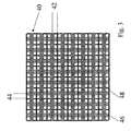
図3は、本発明の好適な実施形態に係る二層感知配列体にレイアウトされた導体を示す略図である。
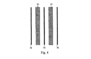
図4は、図3の配列体のフォイルの一つの拡大を示す簡易図である。
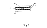
図5は、本発明の好適な実施形態に係る、相互に重ね合わされかつスペーサによって分離された二つのフォイルを示す簡易縦断面図である。
図6は、フォイル間に配置された分離層を上から見た簡易平面図である。
図7は、図1のデジタル処理装置の好適な実施形態の簡易ブロック図である。
図8は、単一接触を検知するための装置を示す簡易配線図である。
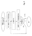
図9は、センサの同時多重接触を検知するための手順の第一の好適な実施形態を示す簡易フローチャートである。
図10は、センサの同時多重接触を検知するための手順の第二の、より効率的な実施形態を示す簡易フローチャートである。
図11は、センサの同時多重接触を検知するための手順の第三の、より正確な実施形態を示す簡易フローチャートである。
The present invention will now be described, by way of example only, with reference to the accompanying drawings. Reference will now be made in detail to the drawings, but the details illustrated are by way of example only and are for purposes of illustrating the preferred embodiments of the present invention in an easy-to-understand manner. It is emphasized that they are presented to provide what is believed to be the most useful and easily understandable explanation. In this regard, the structural details of the present invention will not be shown in more detail than is necessary for a basic understanding of the present invention, but the description in accordance with the drawings shows how to implement some forms of the present invention. It will be clear to those skilled in the art whether this is possible.
FIG. 1 is a simplified block diagram of a dual technology sensor according to a first preferred embodiment of the present invention.
FIG. 2 is a screen display showing a virtual keyboard.
FIG. 3 is a schematic diagram illustrating conductors laid out in a two-layer sensing array according to a preferred embodiment of the present invention.
FIG. 4 is a simplified diagram illustrating one enlargement of the foil of the array of FIG.
FIG. 5 is a simplified longitudinal cross-sectional view showing two foils superimposed on each other and separated by a spacer, according to a preferred embodiment of the present invention.
FIG. 6 is a simplified plan view of the separation layer disposed between the foils as viewed from above.
FIG. 7 is a simplified block diagram of a preferred embodiment of the digital processing apparatus of FIG.
FIG. 8 is a simplified wiring diagram showing an apparatus for detecting a single contact.
FIG. 9 is a simplified flowchart illustrating a first preferred embodiment of a procedure for detecting simultaneous multiple contact of sensors.
FIG. 10 is a simplified flowchart illustrating a second, more efficient embodiment of the procedure for detecting simultaneous multiple contact of sensors.
FIG. 11 is a simplified flowchart illustrating a third, more accurate embodiment of the procedure for detecting simultaneous multiple contact of a sensor.
本実施形態は、物理的オブジェクトの位置、および関連する場合にはアイデンティティを検知することができ、さらに、ディスプレイ上での直接指入力を可能にすることができる、パターン形成された透明な導電性フォイルシステムを開示する。実施形態の主な用途は、「オンスクリーン」または仮想キーボードのスタイラス操作および自然かつ直感的指操作の両方を可能にすることである。実施形態は単一デジタイザシステムを提供するので、モバイル装置に組み込むのに特に有用である。しかし、それらは、ユーザがコンピュータシステムとインタラクトする必要があるどんな状況でも、直感的かつ柔軟なデータ入力またはユーザインタラクションシステムとして有用である。 This embodiment is a patterned transparent conductive material that can sense the location of physical objects and, where relevant, identity, and can also allow direct finger input on the display A foil system is disclosed. The main application of the embodiment is to allow both “on-screen” or virtual keyboard stylus operation and natural and intuitive finger operation. Embodiments are particularly useful for incorporation into mobile devices because they provide a single digitizer system. However, they are useful as an intuitive and flexible data entry or user interaction system in any situation where a user needs to interact with a computer system.
本実施形態はまた、多重同時接触を感知することができ、かつしたがっていわゆる和音操作をサポートすることができるタッチスクリーンをも開示する。 This embodiment also discloses a touch screen that can sense multiple simultaneous contacts and thus can support so-called chord manipulation.
実施形態はしたがって、上述した先行技術の弱点を克服するような仕方で仮想キーボードをサポートするために使用することができる。実施形態は、電磁技術および接触感応技術を単一の透明なフォイルシステムに結合する。加えて、好適な実施形態は、同時の二つ以上の接触入力を検知することを可能にし、それによって和音キー操作を可能にする。 Embodiments can therefore be used to support a virtual keyboard in a manner that overcomes the weaknesses of the prior art described above. Embodiments combine electromagnetic technology and touch sensitive technology into a single transparent foil system. In addition, the preferred embodiment allows for detecting two or more simultaneous touch inputs, thereby allowing chord key operation.
さらに詳しくは、本発明の実施形態は、スタイラスのような物理的オブジェクトの電磁気学を使用した検出、および単一の透明なオーバレイフォイルシステムを使用した指接触操作の検出の両方をサポートする、新しい型のフラットパネルディスプレイデジタイザを提供する。 More particularly, embodiments of the present invention support a new detection that uses both electromagnetic detection of physical objects such as styluses and detection of finger touch operations using a single transparent overlay foil system. A flat panel display digitizer of the type.
実施形態は、コンピューティングシステムの一部の内蔵品として、またはアドオン付属物として設けることができる。 Embodiments can be provided as part of a computing system or as an add-on accessory.
本発明に係るデジタイザの原理および動作は、図面および付随する説明を参照することによって一層よく理解することができる。 The principles and operation of a digitizer according to the present invention may be better understood with reference to the drawings and accompanying descriptions.
本発明の少なくとも一実施形態を詳細に説明する前に、本発明はその適用を以下の説明で記述し、あるいは図面に示す構成部品の構造および配列の詳細に限定されないことを理解されたい。本発明は他の実施形態が可能であり、あるいは様々な方法で実施または実行することができる。また、本書で用いる語法および専門用語は説明を目的とするものであって、限定とみなすべきではないことも理解されたい。 Before describing at least one embodiment of the present invention in detail, it is to be understood that the present invention is not limited to the details of the construction and arrangement of components set forth in the following description or illustrated in the drawings. The invention is capable of other embodiments or of being practiced or carried out in various ways. It should also be understood that the terminology and terminology used herein is for illustrative purposes and should not be considered limiting.
今、図1を参照すると、それは、本発明の第一の好適な実施形態に係る一体化技術のデジタイザを示す簡易ブロック図である。例えばモバイルコンピューティング装置に組み込むためのデジタイザ10は、電磁気および接触感応性透明導体を結合した、透明な感知配列体12を含む。センサ配列体12は一般的に、LCDまたは他の種類のコンピュータディスプレイ上に配置される。好ましくはセンサのフレームに取り付けられるフロントエンドASIC14は、電磁気センサ導体によって出力される信号を処理し、標本化する。標本化された信号は好ましくは、電磁気サブシステム専用であり、以下で電磁(EM)バス18と呼ぶデータバス18を介してデジタル処理装置16に転送される。抵抗バス20は、デジタル装置16とタッチセンサとの間で接触信号を転送する。接触信号の場合、バスに沿っての信号転送は、後でさらに詳細に説明する通り、双方向である。
Reference is now made to FIG. 1, which is a simplified block diagram illustrating an integrated technology digitizer according to a first preferred embodiment of the present invention. For example, a
デジタル装置16は、電磁気および接触感応信号の両方を処理することが好ましい。後でさらに詳細に説明する通り、処理の結果は、電磁気的に突き止められ、かつ/または識別されたオブジェクト、例えば一つまたはそれ以上のスタイラスの一連の位置、およびセンサに接触した一つまたはそれ以上の指の位置である。デジタルプロセッサの出力は、インタフェース24を介してホストコンピューティング装置22に転送することが好ましい。好適な実施形態では、デジタルユニットは、単純なシリアルインタフェースを介してホストと通信する。USBのような追加インタフェースを使用することもできる。
The
ホストコンピュータはスタイラスの位置およびモードをマウス入力として解釈することが好ましい。今、図2を参照すると、それは仮想キーボードを使用するモバイルコンピューティング装置の典型的なディスプレイ30を示す簡易スクリーン図解である。ホストスクリーンディスプレイに一般的に提示することができる種類の仮想キーボード32が示されている。仮想キーボードは、標準キーボードレイアウトに配列された標準キーボードキーの図解を含む。ユーザは、指またはスタイラスのようなポインティング装置のいずれかを使用して、スクリーンのディスプレイのキーに対応する位置に触れることができ、検知された位置は対応するキーボード入力と解釈される。
The host computer preferably interprets the stylus position and mode as mouse input. Reference is now made to FIG. 2, which is a simplified screen illustration showing a
本発明の好適な実施形態では、接触検知は、キーボードが配置されそうな画面の下方部分にだけ延在し、スタイラス感知はスクリーン全体に延在する。そのような実施形態は部品数の低減を導き、したがってより大きい信頼性に結びついたコストの低減を導く。当業者は、各感知システムがスクリーンの一部分だけに限定されるものを含め、他の構成が可能であることを理解されるであろう。 In a preferred embodiment of the present invention, touch detection extends only to the lower part of the screen where the keyboard is likely to be placed, and stylus detection extends to the entire screen. Such an embodiment leads to a reduction in the number of parts and thus a reduction in cost associated with greater reliability. Those skilled in the art will appreciate that other configurations are possible, including those in which each sensing system is limited to only a portion of the screen.
米国特許出願第09/628334号には、フラットパネルディスプレイの頂面に配置されたスタイラスのような物理的オブジェクトを検出することができる、電磁気ベースの感知システムが記載されている。そこに開示された実施形態は、一方が一組の縦導体を含み、他方が一組の横導体を含む、好ましくは有機導電線がパターン形成されて成る、二つの透明フォイルから作られたシステムを記載している。物理的オブジェクトは、二組のフォイルを取り囲む励磁コイルによって付勢される共振回路を含む。付勢のためのトリガ信号は、事前設定された間隔で信号ジェネレータによって提供されることが好ましい。物理的オブジェクトの正確な位置は、こうして付勢された結果として物理的オブジェクトによって出力される信号を処理することによって決定される。出力された信号は、横および縦導体の格子によって感知される。信号処理は周囲のセンサ間の捕間を見込んでいるので、感知分解能は格子サイズより高い。 US patent application Ser. No. 09 / 628,334 describes an electromagnetic-based sensing system that can detect a physical object such as a stylus located on the top surface of a flat panel display. An embodiment disclosed therein is a system made from two transparent foils, preferably patterned with organic conductive lines, one containing a set of longitudinal conductors and the other containing a set of transverse conductors. Is described. The physical object includes a resonant circuit energized by an excitation coil that surrounds the two sets of foils. The trigger signal for activation is preferably provided by the signal generator at preset intervals. The exact position of the physical object is determined by processing the signal output by the physical object as a result of this biasing. The output signal is sensed by a grid of horizontal and vertical conductors. Since signal processing allows for gaps between surrounding sensors, the sensing resolution is higher than the grid size.
上記の出願と同様に、本発明の好適な実施形態では、物理的オブジェクトの共振回路によって送信される電磁信号の発振は、導体の二次元マトリックスによって感知することができる。導電線は透明フォイル上にパターン形成され、線間は非導電性領域によって分離される。しかし、本発明の実施形態では、導電ストライプ(代替的に圧力ストライプと呼ばれる)が、フォイルの各々における電磁導体の間にパターン形成される。これらの導電ストライプは、接触圧力を感知するのに使用される。導電線および圧力ストライプは有機導電性材料から作成することが好ましい。 Similar to the above application, in a preferred embodiment of the present invention, the oscillation of the electromagnetic signal transmitted by the resonant circuit of the physical object can be sensed by a two-dimensional matrix of conductors. Conductive lines are patterned on the transparent foil and the lines are separated by non-conductive areas. However, in embodiments of the present invention, conductive stripes (alternatively referred to as pressure stripes) are patterned between the electromagnetic conductors in each of the foils. These conductive stripes are used to sense contact pressure. Conductive lines and pressure stripes are preferably made from an organic conductive material.
導電線は、均一の導電層からエッチングすることによって形成することができ、あるいはフォイル上に印刷することができる。さらなる代替実施形態では、一層の導電性材料を設け、次いで導電が必要でない場所にパッシベーションプロセスを行なう。 The conductive lines can be formed by etching from a uniform conductive layer or can be printed on the foil. In a further alternative embodiment, a layer of conductive material is provided and then a passivation process is performed where no conduction is required.
今、図3を参照すると、それは、本発明の好適な実施形態に係る二層感知配列体上にレイアウトされた導体を示す略図である。図3で使用される配列体は抵抗マトリックスとして知られている。配列体40は透明導体の二次元格子から形成することが好ましい。配列体は、第一組の平行導電線42を含む第一フォイル層および第二組の平行導電線44を含む第二フォイル層の二つのフォイル層を含むことが好ましい。フォイルは、第二組の平行導電線が第一組に対して実質的に直交するように配置することが好ましい。
Reference is now made to FIG. 3, which is a schematic diagram illustrating conductors laid out on a two-layer sensing array in accordance with a preferred embodiment of the present invention. The array used in FIG. 3 is known as a resistance matrix. The
好適な実施形態では、接触感応性の幅広導電ストライプ46は、第一および第二層の各々におけるEM感応性の狭幅導電線48の間にパターン形成される。接触感応性ストライプは必ずしも幅広である必要はないことに注意されたい。別の好適な実施形態では、それらは導電線と同じ幅である。導電ストライプ間の間隔は、それが指を検知する必要のある分解能レベルに適するように選択することが好ましい。EM感応性の狭幅線は、スタイラスからの電磁放射を検知し、信号処理のレベルに依存する分解能レベルを有する。分解能レベルは導電ストライプより高いことが好ましく、関連用途の要件に合わせて選択することが好ましい。周囲のセンサ線で受け取る信号間の捕間を実行することによって、高い分解能を達成することができる。
In a preferred embodiment, contact sensitive wide
今、図4を参照すると、それは、図3の配列体のフォイルの一つの拡大を示す簡易図である。層は、一実施形態では、格子の配向の一方、すなわち縦または横の平行な導体を含む。接触圧力を感知するのに使用される接触感応性の幅広導電ストライプ50および52は、電磁アンテナとして使用される導電線54、56および58の間にパターン形成される。このようにして、導電ストライプは二つのフォイルの各々の上の導電線の対の間にパターン形成される。次いで二つのフォイルは重ね合わされて、一つの透明フォイル上に配置された横ストライプおよび網一つの透明フォイル上に配置された縦ストライプを含む二次元格子を形成する。
Reference is now made to FIG. 4, which is a simplified diagram showing one enlargement of the foil of the array of FIG. The layer comprises, in one embodiment, parallel conductors in one of the orientations of the lattice, ie, longitudinal or transverse. Contact sensitive wide
今、図5を参照すると、それは、本発明の好適な実施形態に係る、相互に重ね合わされ、かつスペーサによって分離された二つのフォイルを示す簡易縦断面図である。 Reference is now made to FIG. 5, which is a simplified longitudinal section showing two foils superimposed on each other and separated by a spacer, according to a preferred embodiment of the present invention.
二つのフォイル60および62はそれぞれ、横センサパターンおよび縦センサパターンを含む。フォイルは相互の上に組み立てられ、非導電性分離層64によって分離される。各フォイルは導電面66および68をそれぞれ有する。フォイルは、各フォイルの導電側が他方のフォイルに対面するように配設される。
The two foils 60 and 62 each include a horizontal sensor pattern and a vertical sensor pattern. The foils are assembled on top of each other and separated by a
今、図6を参照すると、それは分離層64を上から見た図を示す簡易図である。上述した通り、フォイルの間に配置される分離層64は、電磁導体のパターンと一致するように構成された、縦70および横72の非導電性分離線の二次元マトリックスを含むことが好ましい。マトリックスは、非導電性分離線の間に配置された空隙74を含むことが好ましい。分離層64は、電磁線が相互に接触したり、あるいは反対側のフォイル上の感圧性ストライプのいずれかに触れるのを防止することによって、かつそれぞれのフォイル上の感圧性ストライプが相互に接触するのを通常防止することによって、回路短絡を防止する。
Reference is now made to FIG. 6, which is a simplified diagram showing a view of the
加えて、マトリックスは弾性材料製である。分離層64は、上述の通り、縦および横の導電ストライプ間に物理的空隙を形成し、こうして、圧力が印加されないときに、ストライプが相互に接触するのを防止することによって、圧力の感知を可能にする。しかし、圧力を印加するとマトリックスは圧搾され、上下層のストライプが空隙74の領域で接触する。同時に、マトリックスの分離線はそれらの間に非導電性分離を設けており、それは圧力の印加時にも保持されるので、隣接する電磁線の間に接触は起きない。
In addition, the matrix is made of an elastic material. The
分離層64のパターン形成は、特定量の追加余裕をもって、電磁導体のパターンと実質的に一致することが好ましい。分離層はこうして、方形または矩形の非導電性マスクを含むことができる。マスクは、センサ製造プロセスの一環として、透明な非導電性接着剤を使用して、フォイル層上に印刷することが好ましい。代替的に、それは、フォイルに塗布された非導電性材料の層からエッチングすることができる。透明な非導電性接着剤とは別に、他の透明または半透明な非導電性材料も適しているかもしれず、透明性および半透明性はフォイルに使用される層の厚さに関係すると考えられる。さらに、電磁導体は特に薄いので、スクリーンの表示を妨害することなく、不透明な材料のマスクを作成することが可能であるかもしれず、そのような実施形態は、映像に対する小さい妨害が重大ではないCNC装置のような特定の産業用分野に特に適しているかもしれない。
It is preferable that the pattern formation of the
本発明の代替実施形態では、分離層64はスペーサドットのマスクを含む。高密度のそのようなスペーサドットは電磁導体の領域に配置され、それらが相互に接触したり、あるいは感圧ストライプに接触することを防止する。より低密度のドットは、圧力が加えられないときにはストライプが相互に接触するのを防止するが、接触圧力により容易に接触することを可能にするのに充分なように、感圧ストライプ間の接点の領域に配置される。別の好適な実施形態では、接点領域にはドットを設けない。
In an alternative embodiment of the present invention, the
今、図7を参照すると、それは、図1のデジタル処理装置16の好適な実施形態の簡易ブロック図である。デジタル処理装置16は、タッチインタフェース80およびEMインタフェース82の二つのインタフェースを含む。タッチインタフェース80は信号を提供し、センサ接触導体から入力を受け取る。EMインタフェース82は、EMセンサから信号を受け取るフロントエンドASIC14と共に動作する。EMインタフェースは、様々なフロントエンド14で標本化されたシリアル入力の信号を受け取り、それらをパラレル表現にパックする。デジタル信号処理装置(DSP)84はタッチインタフェースおよびEMインタフェースの両方に接続され、それぞれのインタフェースからのデータを処理して、EMサブシステムによって検知されるスタイラスのような物理的オブジェクトの位置、および接触サブシステムによって検知される指接触の位置の両方を決定する。DSPによって算出された位置は、リンク、例えばシリアルリンク86を介して、ホストコンピュータに送られる。DSPはフラッシュメモリ88およびRAM90に関連付けられることが好ましい。DSP演算コードは、フラッシュメモリ88に格納することが好ましく、標本化データはRAM90に格納することが好ましい。信号ジェネレータ91は、EMサブシステム用のトリガ信号を提供する。
Reference is now made to FIG. 7, which is a simplified block diagram of a preferred embodiment of the
好適な実施形態では、タッチインタフェース80はPLD(プログラマブル論理素子)によって実現される。各圧力ストライプは、入力および出力の両方として使用することのできるPLD IOピンの一つに直接接続される。代替的に、入力および出力信号を増幅するために、PLDとセンサ導体との間に双方向バッファを配置することができる。
In the preferred embodiment, the
今、図8を参照すると、それは、単一接触を検出するための装置を示す簡易配線図である。上述の通り、タッチインタフェース80を実現するPLD91は、この場合は出力として使用されるそのIOピン92の一つに、一般的には静的DCレベルの信号を出力する。信号は縦ストライプ94に提供される。縦ストライプ94は横ストライプ96との通常非接触接点を有し、次に横ストライプはプルダウン抵抗器98に接続される。縦導体94が横導体96と接触しない限り、プルダウン抵抗器98は、横導体96に接続されたPLD入力ピン100の入力電圧を低レベルにする。指の圧力は縦ストライプ94および横ストライプ96を接続し、出力ピン92の高電圧を入力ピン100に移送させる。PLD入力で検出された高レベルは、接触検知と解釈される。
Reference is now made to FIG. 8, which is a simplified wiring diagram illustrating an apparatus for detecting a single contact. As described above, the
DSP84は、PLD91のIOピンの構成および状態を制御することが好ましい。DSP84は、どのピンが現在出力またはトリガ信号を提供しているか、かつどれが入力の検出に設定されているかを決定する。すなわち、それはI/Oピンのうちのどれが「1」に設定され、どれが「0」に設定されているかを決定し、かつそれは入力ピンのレベルを読み取る。二つ以上の出力を同時に「1」に設定することができ、「0」についても同様である。
The
今、図9を参照すると、それは、同時多重指接触を検出するために接触検知器を循環するための手順の第一の好適な実施形態を示すフローチャートである。図9の手順に従って、格子軸の一つにおける圧力ストライプの各々を一度に一つのストライプづつループし、直交する軸上の格子ストライプの各々における信号を次々に読み取ることによって、多重接触検知を達成することができる。 Reference is now made to FIG. 9, which is a flow chart illustrating a first preferred embodiment of a procedure for cycling a contact detector to detect simultaneous multiple finger contact. Multiple touch sensing is achieved by looping each of the pressure stripes on one of the grid axes one stripe at a time and reading the signal on each of the grid stripes on the orthogonal axes one after the other according to the procedure of FIG. be able to.
さらに詳しくは、軸の一方、縦または横のいずれかをトリガ用に選択し、他方を読取り用に選択する。読取り用に選択した軸、例えば横軸では、各ストライプは上述したように一般的にプルダウン抵抗器によって入力に設定され、それは実際には低位状態を意味する。次いで、直交軸、例えば縦軸におけるストライプのうちの最初のものが1に設定される。横ストライプの各々が今読み取られる。横ストライプのいずれかにおける1の存在は、その横ストライプと第一の縦ストライプとの間の接点に指があることを示す。プロセスは、スクリーン全体がスキャンされるまで、縦ストライプの各々について一つづつ繰り返される。 More specifically, one of the axes, either vertical or horizontal, is selected for triggering and the other is selected for reading. On the axis selected for reading, eg, the horizontal axis, each stripe is typically set to input by a pull-down resistor as described above, which actually means a low state. The first of the stripes on the orthogonal axis, eg, the vertical axis, is then set to 1. Each of the horizontal stripes is now read. The presence of 1 in any of the horizontal stripes indicates that there is a finger at the contact point between that horizontal stripe and the first vertical stripe. The process is repeated one for each vertical stripe until the entire screen is scanned.
信頼できる結果を得るために、循環は、指がスクリーン上でタイプする可能性のある最高速度と少なくとも同じ速度で実行することが好ましい。図9の手順の弱点は多数の検出ステップである。該手順はn*m段階を必要とする。ここでnは縦ストライプの個数を表わし、mは横ストライプの個数を表わす。そのような手順を使用して、上述した速度を達成することは難しい。 In order to obtain reliable results, the cycling is preferably performed at a speed that is at least as fast as the finger can type on the screen. The weakness of the procedure of FIG. 9 is a number of detection steps. The procedure requires n * m steps. Here, n represents the number of vertical stripes, and m represents the number of horizontal stripes. Using such a procedure, it is difficult to achieve the speeds described above.
今、図10を参照すると、それは、多重接触を検知するためのより高速の手順を示す簡易フローチャートである。信号、一般的に「1」が、一方の軸のストライプ群に印加される。該群は一般的に、その軸の全てのストライプとすることができる。その後、他方の軸のストライプの各々の入力が次々に読み取られる。次いで、同じ信号が第二軸のストライプ群に印加され、第一軸のストライプの各々で読取りが行なわれる。使用した群が軸全体である場合には、図10の手順はn+mステップを必要とし、図9のそれに対してかなりの低減である。しかし、該手順は、全ての可能な接触の組合せの間で区別することができず、したがって部分的にしか信頼できない。特に、各軸に二つまたはそれ以上の信号検知が存在する場合には、曖昧さが生じる。 Reference is now made to FIG. 10, which is a simplified flowchart illustrating a faster procedure for detecting multiple contacts. A signal, generally “1”, is applied to the stripe group on one axis. The group can generally be all stripes of its axis. Thereafter, each input of the other axis stripe is read one after another. The same signal is then applied to the second axis stripe group, and a read is performed on each of the first axis stripes. If the group used is the entire axis, the procedure of FIG. 10 requires n + m steps, which is a considerable reduction over that of FIG. However, the procedure cannot distinguish between all possible contact combinations and is therefore only partially reliable. In particular, ambiguity arises when there are two or more signal detections on each axis.
今、図11を参照すると、それは、多重接触を検知するための手順の第三の好適な実施形態を示す簡易フローチャートである。 Reference is now made to FIG. 11, which is a simplified flowchart illustrating a third preferred embodiment of a procedure for detecting multiple touches.
図11の実施形態では、図9および10の両方の手順を結合して、完全に信頼できる検出アルゴリズムを生成する。図11の手順の第一段階は、単に図10の手順を実行することである。すなわち、第一信号を一方の軸の全てのストライプに印加し、他方の軸で応答を探す。次いで、第二信号を他方の軸の全てのストライプに印加しながら、第一軸で応答を探す。 In the embodiment of FIG. 11, the procedures of both FIGS. 9 and 10 are combined to produce a fully reliable detection algorithm. The first step in the procedure of FIG. 11 is simply to execute the procedure of FIG. That is, the first signal is applied to all stripes on one axis and the response is searched on the other axis. The second signal is then applied to all stripes on the other axis, looking for a response on the first axis.
図10の手順の結果を使用して、曖昧さが存在するかどうかを決定し、存在する場合には、どのストライプが疑わしいストライプとみなすことができるかを決定する。両方の軸に二つ以上の検知信号がある場合、曖昧さが存在するとみなされる。そのような場合、疑わしいストライプとは、検知信号を発生したストライプである。そのような場合、曖昧さを解消する。そのような解消を達成するために、アルゴリズムは、軸の一方における疑わしいストライプの各々を次々にループし、他方の軸の疑わしいストライプの各々の応答を探す。したがって、該手順は、曖昧さが存在しない限り、ステップの数はn+mのままであるので、処理時間に対してほとんどコストを掛けずに明白な結果を提供することができる。曖昧さが存在する場合には、追加される追加ステップの数は、疑わしいストライプの積にすぎない。好適な実施形態では、ループ用に選択する軸は、疑わしいストライプの数が小さい方の軸である。したがって、第一軸にp個の疑わしいストライプがあり、第二軸にq個の疑わしいストライプがある場合、ステップの総数はn+m+(q*p)である。 The results of the procedure of FIG. 10 are used to determine whether ambiguity exists and, if so, which stripes can be considered suspicious stripes. Ambiguity is considered to exist if there are more than one detection signal on both axes. In such a case, the suspicious stripe is the stripe that generated the detection signal. In such cases, the ambiguity is resolved. To achieve such resolution, the algorithm loops through each suspicious stripe on one of the axes in turn, looking for a response for each suspicious stripe on the other axis. Thus, the procedure can provide obvious results with little cost to processing time since the number of steps remains n + m unless there is ambiguity. If there is ambiguity, the number of additional steps added is only a product of suspicious stripes. In the preferred embodiment, the axis selected for the loop is the axis with the smaller number of suspicious stripes. Thus, if there are p suspicious stripes on the first axis and q suspicious stripes on the second axis, the total number of steps is n + m + (q * p).
本発明の追加の目的、利点、および新規の特徴は、限定するものと意図されていない以下の例を考察することにより、当業の通常の熟練者には明らかになるであろう。加えて、本書で上述しかつ請求の範囲に記載する本発明の様々な実施形態および態様の各々が、以下の例に実験的裏づけを見出すであろう。 Additional objects, advantages, and novel features of the present invention will become apparent to those of ordinary skill in the art upon consideration of the following examples, which are not intended to be limiting. In addition, each of the various embodiments and aspects of the invention described hereinabove and described in the claims will find experimental support in the following examples.
分かり易くするために別個の実施形態の文脈で説明した本発明の特定の特徴は、単一の実施形態で組み合せて提供することもできることを理解されたい。逆に、簡潔にするために単一の実施形態の文脈で説明した本発明の様々な特徴を別々に、または任意の適切な部分組合せにより提供することもできる。 It should be understood that certain features of the invention described in the context of separate embodiments for clarity may also be provided in combination in a single embodiment. Conversely, various features of the invention described in the context of a single embodiment for the sake of brevity may be provided separately or in any appropriate subcombination.
本発明を特定の実施形態に関連して説明したが、多くの代替、変形、および変化が当業者には明らかになることが明白である。したがって、請求の範囲に記載する精神および幅広い範囲内に該当する代替、変形、および変化を全て包含するつもりである。本明細書に示した全ての刊行物、特許、および特許出願は、あたかも個々の刊行物、特許、または特許出願の各々が明確かつ個別に参照によって本書に組み込まれると指摘されたかのように、その場合と同程度に、参照によってそっくりそのまま本明細書に組み込まれる。加えて、本願における参考文献の引用または識別は、そのような文献が本願の先行技術として利用可能であることの承認とは解釈されないものとする。 Although the invention has been described with reference to particular embodiments, it is evident that many alternatives, modifications, and variations will become apparent to those skilled in the art. Accordingly, it is intended to embrace all such alternatives, modifications and variations that fall within the spirit and broad scope of the appended claims. All publications, patents, and patent applications mentioned in this specification are intended to be used as if each individual publication, patent, or patent application was specifically and individually indicated to be incorporated herein by reference. To the extent that is the case, it is incorporated herein by reference in its entirety. In addition, citation or identification of any reference in this application shall not be construed as an admission that such reference is available as prior art to the present application.
Claims (45)
第二型の感知方法を使用する第二の種類のユーザインタラクションを感知するための第二センサを有する第二のセンサ群と、を備え、
前記第一および第二の種類のユーザインタラクションが相互に独立であり、前記第一および第二のセンサ群の少なくとも一部が単一フォイルの感知層にパターン形成され、同一位置にインターリーブするように配置されて成る、デジタルシステムへのユーザ入力のための装置。A first group of sensors having sensors for sensing a first type of user interaction using a first type of sensing method;
A second sensor group having a second sensor for sensing a second type of user interaction using a second type of sensing method;
The first and second types of user interaction are independent of each other such that at least a portion of the first and second sensor groups are patterned on a single foil sensing layer and interleaved at the same location. Arranged device for user input to a digital system.
第一型のユーザインタラクションを検知するための第一検知システムのセンサおよび第二型のユーザインタラクションを検知するための第二検知システムのセンサが埋め込まれた第一透明フォイルと、
前記第一透明フォイル上に重ね合わされ、それから可撓式に離れて配置された第二透明フォイルであって、埋め込まれた前記第一検知システムおよび前記第二検知システムのセンサをさらに有する第二透明フォイルと、
を備えたセンサ配列体。A sensor array for overlaying on a visual display screen,
A first transparent foil embedded with a sensor of a first detection system for detecting a first type of user interaction and a sensor of a second detection system for detecting a second type of user interaction;
A second transparent foil superimposed on and then flexibly spaced from the first transparent foil, the second transparent foil further comprising an embedded sensor of the first sensing system and the second sensing system Foil,
A sensor array comprising:
Applications Claiming Priority (3)
| Application Number | Priority Date | Filing Date | Title |
|---|---|---|---|
| US33377001P | 2001-11-29 | 2001-11-29 | |
| US10/270,373 US6762752B2 (en) | 2001-11-29 | 2002-10-15 | Dual function input device and method |
| PCT/IL2002/000957 WO2003046882A1 (en) | 2001-11-29 | 2002-11-28 | Dual function input device and method |
Publications (3)
| Publication Number | Publication Date |
|---|---|
| JP2005510814A JP2005510814A (en) | 2005-04-21 |
| JP2005510814A5 JP2005510814A5 (en) | 2005-12-22 |
| JP4038480B2 true JP4038480B2 (en) | 2008-01-23 |
Family
ID=26954243
Family Applications (1)
| Application Number | Title | Priority Date | Filing Date |
|---|---|---|---|
| JP2003548226A Expired - Lifetime JP4038480B2 (en) | 2001-11-29 | 2002-11-28 | Dual function input device and method |
Country Status (4)
| Country | Link |
|---|---|
| US (1) | US6762752B2 (en) |
| JP (1) | JP4038480B2 (en) |
| AU (1) | AU2002356407A1 (en) |
| WO (1) | WO2003046882A1 (en) |
Families Citing this family (225)
| Publication number | Priority date | Publication date | Assignee | Title |
|---|---|---|---|---|
| US8825152B2 (en) | 1996-01-08 | 2014-09-02 | Impulse Dynamics, N.V. | Modulation of intracellular calcium concentration using non-excitatory electrical signals applied to the tissue |
| US7167748B2 (en) | 1996-01-08 | 2007-01-23 | Impulse Dynamics Nv | Electrical muscle controller |
| JP4175662B2 (en) | 1996-01-08 | 2008-11-05 | インパルス ダイナミクス エヌ.ヴイ. | Electric muscle control device |
| US9289618B1 (en) | 1996-01-08 | 2016-03-22 | Impulse Dynamics Nv | Electrical muscle controller |
| US8321013B2 (en) | 1996-01-08 | 2012-11-27 | Impulse Dynamics, N.V. | Electrical muscle controller and pacing with hemodynamic enhancement |
| US9713723B2 (en) | 1996-01-11 | 2017-07-25 | Impulse Dynamics Nv | Signal delivery through the right ventricular septum |
| GB9722766D0 (en) | 1997-10-28 | 1997-12-24 | British Telecomm | Portable computers |
| US7808479B1 (en) | 2003-09-02 | 2010-10-05 | Apple Inc. | Ambidextrous mouse |
| US9239673B2 (en) | 1998-01-26 | 2016-01-19 | Apple Inc. | Gesturing with a multipoint sensing device |
| US7663607B2 (en) | 2004-05-06 | 2010-02-16 | Apple Inc. | Multipoint touchscreen |
| US7844914B2 (en) | 2004-07-30 | 2010-11-30 | Apple Inc. | Activating virtual keys of a touch-screen virtual keyboard |
| WO1999038149A1 (en) | 1998-01-26 | 1999-07-29 | Wayne Westerman | Method and apparatus for integrating manual input |
| US7614008B2 (en) | 2004-07-30 | 2009-11-03 | Apple Inc. | Operation of a computer with touch screen interface |
| US8479122B2 (en) | 2004-07-30 | 2013-07-02 | Apple Inc. | Gestures for touch sensitive input devices |
| US9292111B2 (en) | 1998-01-26 | 2016-03-22 | Apple Inc. | Gesturing with a multipoint sensing device |
| US7265494B2 (en) | 1998-10-09 | 2007-09-04 | Azoteq Pty Ltd. | Intelligent user interface with touch sensor technology |
| US7528508B2 (en) | 1998-10-09 | 2009-05-05 | Azoteq Pty Ltd. | Touch sensor user interface with compressible material construction |
| EP1147176B1 (en) * | 1999-02-04 | 2009-12-16 | Pluristem Ltd. | Method and apparatus for maintenance and expansion of hemopoietic stem cells and/or progenitor cells |
| US8019421B2 (en) | 1999-03-05 | 2011-09-13 | Metacure Limited | Blood glucose level control |
| WO2006073671A1 (en) | 2004-12-09 | 2006-07-13 | Impulse Dynamics Nv | Protein activity modification |
| US8666495B2 (en) | 1999-03-05 | 2014-03-04 | Metacure Limited | Gastrointestinal methods and apparatus for use in treating disorders and controlling blood sugar |
| US8346363B2 (en) | 1999-03-05 | 2013-01-01 | Metacure Limited | Blood glucose level control |
| US9101765B2 (en) | 1999-03-05 | 2015-08-11 | Metacure Limited | Non-immediate effects of therapy |
| US8700161B2 (en) | 1999-03-05 | 2014-04-15 | Metacure Limited | Blood glucose level control |
| US7030861B1 (en) * | 2001-02-10 | 2006-04-18 | Wayne Carl Westerman | System and method for packing multi-touch gestures onto a hand |
| US7730401B2 (en) * | 2001-05-16 | 2010-06-01 | Synaptics Incorporated | Touch screen with user interface enhancement |
| JP2003280800A (en) * | 2002-01-21 | 2003-10-02 | Matsushita Electric Ind Co Ltd | Touch panel |
| US6882337B2 (en) * | 2002-04-18 | 2005-04-19 | Microsoft Corporation | Virtual keyboard for touch-typing using audio feedback |
| US20030206161A1 (en) * | 2002-05-01 | 2003-11-06 | Fa-Chung Liu | Tablet integrated type monitor filter |
| US7477242B2 (en) | 2002-05-20 | 2009-01-13 | 3M Innovative Properties Company | Capacitive touch screen with conductive polymer |
| US11275405B2 (en) | 2005-03-04 | 2022-03-15 | Apple Inc. | Multi-functional hand-held device |
| US7656393B2 (en) | 2005-03-04 | 2010-02-02 | Apple Inc. | Electronic device having display and surrounding touch sensitive bezel for user interface and control |
| JP3630153B2 (en) * | 2002-07-19 | 2005-03-16 | ソニー株式会社 | Information display input device, information display input method, and information processing device |
| EP1550105B1 (en) * | 2002-08-29 | 2011-05-18 | N-Trig Ltd. | Transparent digitiser |
| US7372455B2 (en) * | 2003-02-10 | 2008-05-13 | N-Trig Ltd. | Touch detection for a digitizer |
| US7840262B2 (en) | 2003-03-10 | 2010-11-23 | Impulse Dynamics Nv | Apparatus and method for delivering electrical signals to modify gene expression in cardiac tissue |
| US11439815B2 (en) | 2003-03-10 | 2022-09-13 | Impulse Dynamics Nv | Protein activity modification |
| US7755616B2 (en) * | 2003-03-28 | 2010-07-13 | Lg Display Co., Ltd. | Liquid crystal display device having electromagnetic type touch panel |
| US8792985B2 (en) | 2003-07-21 | 2014-07-29 | Metacure Limited | Gastrointestinal methods and apparatus for use in treating disorders and controlling blood sugar |
| CN100520687C (en) * | 2003-07-21 | 2009-07-29 | 皇家飞利浦电子股份有限公司 | Touch sensitive display for a portable device and the portable device |
| US9024884B2 (en) | 2003-09-02 | 2015-05-05 | Apple Inc. | Touch-sensitive electronic apparatus for media applications, and methods therefor |
| US7307624B2 (en) * | 2003-12-30 | 2007-12-11 | 3M Innovative Properties Company | Touch sensor with linearized response |
| GB0401991D0 (en) * | 2004-01-30 | 2004-03-03 | Ford Global Tech Llc | Touch screens |
| FR2866726B1 (en) * | 2004-02-23 | 2006-05-26 | Jazzmutant | CONTROLLER BY HANDLING VIRTUAL OBJECTS ON A MULTI-CONTACT TOUCH SCREEN |
| US11779768B2 (en) | 2004-03-10 | 2023-10-10 | Impulse Dynamics Nv | Protein activity modification |
| US8352031B2 (en) | 2004-03-10 | 2013-01-08 | Impulse Dynamics Nv | Protein activity modification |
| US7492358B2 (en) * | 2004-06-15 | 2009-02-17 | International Business Machines Corporation | Resistive scanning grid touch panel |
| TWI291642B (en) * | 2004-07-15 | 2007-12-21 | N trig ltd | A tracking window for a digitizer system |
| EP1787281A2 (en) * | 2004-07-15 | 2007-05-23 | N-Trig Ltd. | Automatic switching for a dual mode digitizer |
| JP4529012B2 (en) * | 2004-07-16 | 2010-08-25 | アオイ電子株式会社 | Nano gripper device |
| JP4405335B2 (en) * | 2004-07-27 | 2010-01-27 | 株式会社ワコム | POSITION DETECTION DEVICE AND INPUT SYSTEM |
| US8381135B2 (en) | 2004-07-30 | 2013-02-19 | Apple Inc. | Proximity detector in handheld device |
| US7653883B2 (en) | 2004-07-30 | 2010-01-26 | Apple Inc. | Proximity detector in handheld device |
| CN101661357B (en) | 2004-08-16 | 2013-07-03 | 苹果公司 | Touch sensitive device and method of increasing the spatial resolution of touch sensitive device |
| CN101014927A (en) * | 2004-09-14 | 2007-08-08 | 诺基亚公司 | Method for using indicating device |
| US7728823B2 (en) * | 2004-09-24 | 2010-06-01 | Apple Inc. | System and method for processing raw data of track pad device |
| EP1805587A1 (en) * | 2004-09-24 | 2007-07-11 | Apple Computer, Inc. | Raw data track pad device and system |
| US7719522B2 (en) * | 2004-09-24 | 2010-05-18 | Apple Inc. | Raw data track pad device and system |
| US8244371B2 (en) | 2005-03-18 | 2012-08-14 | Metacure Limited | Pancreas lead |
| EP1898991B1 (en) | 2005-05-04 | 2016-06-29 | Impulse Dynamics NV | Protein activity modification |
| US9019209B2 (en) | 2005-06-08 | 2015-04-28 | 3M Innovative Properties Company | Touch location determination involving multiple touch location processes |
| WO2007017848A2 (en) | 2005-08-11 | 2007-02-15 | N-Trig Ltd. | Apparatus for object information detection and methods of using same |
| US7294089B2 (en) * | 2005-08-15 | 2007-11-13 | Ford Global Technologies, Llc | Multiple-speed automatic transmission |
| CN102841713A (en) * | 2005-09-15 | 2012-12-26 | 苹果公司 | System and method for processing raw data of track pad device |
| US7864160B2 (en) * | 2005-10-05 | 2011-01-04 | 3M Innovative Properties Company | Interleaved electrodes for touch sensing |
| US9064772B2 (en) * | 2005-10-07 | 2015-06-23 | Integrated Digital Technologies, Inc. | Touch screen system having dual touch sensing function |
| US7868874B2 (en) | 2005-11-15 | 2011-01-11 | Synaptics Incorporated | Methods and systems for detecting a position-based attribute of an object using digital codes |
| US8018440B2 (en) | 2005-12-30 | 2011-09-13 | Microsoft Corporation | Unintentional touch rejection |
| KR101230309B1 (en) * | 2006-01-27 | 2013-02-06 | 삼성디스플레이 주식회사 | Display device and processing apparatus of sensing signal |
| JP4799237B2 (en) * | 2006-03-27 | 2011-10-26 | 三洋電機株式会社 | Displacement detection sensor, displacement detection device, and terminal device |
| US8144125B2 (en) | 2006-03-30 | 2012-03-27 | Cypress Semiconductor Corporation | Apparatus and method for reducing average scan rate to detect a conductive object on a sensing device |
| US7511702B2 (en) * | 2006-03-30 | 2009-03-31 | Apple Inc. | Force and location sensitive display |
| US7538760B2 (en) | 2006-03-30 | 2009-05-26 | Apple Inc. | Force imaging input device and system |
| US8264466B2 (en) * | 2006-03-31 | 2012-09-11 | 3M Innovative Properties Company | Touch screen having reduced visibility transparent conductor pattern |
| US7978181B2 (en) | 2006-04-25 | 2011-07-12 | Apple Inc. | Keystroke tactility arrangement on a smooth touch surface |
| US8279180B2 (en) | 2006-05-02 | 2012-10-02 | Apple Inc. | Multipoint touch surface controller |
| WO2007129085A2 (en) * | 2006-05-09 | 2007-11-15 | Sensopad Limited | Navigation arrangement for an electronic device |
| US8059015B2 (en) | 2006-05-25 | 2011-11-15 | Cypress Semiconductor Corporation | Capacitance sensing matrix for keyboard architecture |
| US8243027B2 (en) | 2006-06-09 | 2012-08-14 | Apple Inc. | Touch screen liquid crystal display |
| EP3264240A1 (en) | 2006-06-09 | 2018-01-03 | Apple Inc. | Touch screen liquid crystal display |
| CN104965621B (en) | 2006-06-09 | 2018-06-12 | 苹果公司 | Touch screen LCD and its operating method |
| US8059102B2 (en) * | 2006-06-13 | 2011-11-15 | N-Trig Ltd. | Fingertip touch recognition for a digitizer |
| US8040321B2 (en) | 2006-07-10 | 2011-10-18 | Cypress Semiconductor Corporation | Touch-sensor with shared capacitive sensors |
| WO2008007372A2 (en) * | 2006-07-12 | 2008-01-17 | N-Trig Ltd. | Hover and touch detection for a digitizer |
| US8686964B2 (en) * | 2006-07-13 | 2014-04-01 | N-Trig Ltd. | User specific recognition of intended user interaction with a digitizer |
| WO2008020446A1 (en) * | 2006-08-15 | 2008-02-21 | N-Trig Ltd. | Gesture detection for a digitizer |
| US9201556B2 (en) | 2006-11-08 | 2015-12-01 | 3M Innovative Properties Company | Touch location sensing system and method employing sensor data fitting to a predefined curve |
| US8547114B2 (en) | 2006-11-14 | 2013-10-01 | Cypress Semiconductor Corporation | Capacitance to code converter with sigma-delta modulator |
| JP4966636B2 (en) * | 2006-12-13 | 2012-07-04 | 株式会社ワコム | Coordinate input device |
| US8207944B2 (en) * | 2006-12-19 | 2012-06-26 | 3M Innovative Properties Company | Capacitance measuring circuit and method |
| US20080150917A1 (en) * | 2006-12-20 | 2008-06-26 | 3M Innovative Properties Company | Oscillator circuit for use in an untethered stylus |
| US20080149401A1 (en) * | 2006-12-20 | 2008-06-26 | 3M Innovative Properties Company | Untethered stylus employing separate communication channels |
| US8243049B2 (en) * | 2006-12-20 | 2012-08-14 | 3M Innovative Properties Company | Untethered stylus employing low current power converter |
| US7956851B2 (en) * | 2006-12-20 | 2011-06-07 | 3M Innovative Properties Company | Self-tuning drive source employing input impedance phase detection |
| US8134542B2 (en) | 2006-12-20 | 2012-03-13 | 3M Innovative Properties Company | Untethered stylus employing separate communication and power channels |
| US7436164B2 (en) * | 2006-12-20 | 2008-10-14 | 3M Innovative Properties Company | Untethered device employing tunable resonant circuit |
| US8040329B2 (en) * | 2006-12-20 | 2011-10-18 | 3M Innovative Properties Company | Frequency control circuit for tuning a resonant circuit of an untethered device |
| US7787259B2 (en) * | 2006-12-28 | 2010-08-31 | 3M Innovative Properties Company | Magnetic shield for use in a location sensing system |
| US8089474B2 (en) * | 2006-12-28 | 2012-01-03 | 3M Innovative Properties Company | Location sensing system and method employing adaptive drive signal adjustment |
| US8040330B2 (en) * | 2006-12-28 | 2011-10-18 | 3M Innovative Properties Company | Untethered stylus empolying multiple reference frequency communication |
| US8493330B2 (en) | 2007-01-03 | 2013-07-23 | Apple Inc. | Individual channel phase delay scheme |
| US9710095B2 (en) | 2007-01-05 | 2017-07-18 | Apple Inc. | Touch screen stack-ups |
| US8058937B2 (en) | 2007-01-30 | 2011-11-15 | Cypress Semiconductor Corporation | Setting a discharge rate and a charge rate of a relaxation oscillator circuit |
| US9348167B2 (en) * | 2007-03-19 | 2016-05-24 | Via Optronics Gmbh | Enhanced liquid crystal display system and methods |
| WO2008120200A2 (en) | 2007-03-29 | 2008-10-09 | N-Trig Ltd. | System and method for multiple object detection on a digitizer system |
| US7924362B2 (en) | 2007-04-20 | 2011-04-12 | Via Optronics, Llc | Bezelless display system having a display assembly with an overlay including a transparent section optically bonded to a display region with an optical layer that includes a pre-cured adhesive preform |
| WO2008133999A1 (en) * | 2007-04-24 | 2008-11-06 | White Electronic Designs Corp. | Interactive display system |
| US8355009B2 (en) * | 2007-04-25 | 2013-01-15 | Mcdermid William J | Method and apparatus for determining coordinates of simultaneous touches on a touch sensor pad |
| US20090009482A1 (en) * | 2007-05-01 | 2009-01-08 | Mcdermid William J | Touch sensor pad user input device |
| US8144126B2 (en) | 2007-05-07 | 2012-03-27 | Cypress Semiconductor Corporation | Reducing sleep current in a capacitance sensing system |
| US9285930B2 (en) | 2007-05-09 | 2016-03-15 | Wacom Co., Ltd. | Electret stylus for touch-sensor device |
| EP2152194A1 (en) * | 2007-05-09 | 2010-02-17 | S.A.E. Afikim | Method and system for predicting calving |
| WO2009006557A1 (en) * | 2007-07-03 | 2009-01-08 | Cypress Semiconductor Corporation | Method for improving scan time and sensitivity in touch sensitive user interface device |
| US8570053B1 (en) | 2007-07-03 | 2013-10-29 | Cypress Semiconductor Corporation | Capacitive field sensor with sigma-delta modulator |
| US8258986B2 (en) | 2007-07-03 | 2012-09-04 | Cypress Semiconductor Corporation | Capacitive-matrix keyboard with multiple touch detection |
| US8169238B1 (en) | 2007-07-03 | 2012-05-01 | Cypress Semiconductor Corporation | Capacitance to frequency converter |
| US20090033632A1 (en) * | 2007-07-30 | 2009-02-05 | Szolyga Thomas H | Integrated touch pad and pen-based tablet input system |
| US7834862B2 (en) * | 2007-09-28 | 2010-11-16 | Au Optronics Corporation | Touch sensor layout design |
| TW200925969A (en) * | 2007-12-11 | 2009-06-16 | Tpk Touch Solutions Inc | Device for scanning and detecting touch point of touch control panel and method thereof |
| FR2925713B1 (en) * | 2007-12-19 | 2010-03-19 | Stantum | MULTICONTACT TOUCH SENSOR WITH SLEEP MODE |
| FR2925716B1 (en) * | 2007-12-19 | 2010-06-18 | Stantum | ELECTRONIC ANALYSIS CIRCUIT WITH SCANNING CHARACTERISTIC MODULATION FOR A PASSIVE MATRIX MULTICONTACT TOUCH SENSOR |
| FR2925715B1 (en) * | 2007-12-19 | 2010-06-18 | Stantum | ELECTRONIC ANALYSIS CIRCUIT WITH ALTERNATING POWER AXIS / DETECTION AXIS FOR MULTICONTACT TOUCH SENSOR WITH PASSIVE MATRIX |
| FR2925714B1 (en) * | 2007-12-19 | 2010-01-15 | Stantum | ELECTRONIC CAPACITIVE / RESISTIVE ALTERNATING ANALYSIS CIRCUIT FOR MULTICONTACT PASSIVE MATRIX TOUCH SENSOR |
| US9367166B1 (en) * | 2007-12-21 | 2016-06-14 | Cypress Semiconductor Corporation | System and method of visualizing capacitance sensing system operation |
| US8525798B2 (en) | 2008-01-28 | 2013-09-03 | Cypress Semiconductor Corporation | Touch sensing |
| US8319505B1 (en) | 2008-10-24 | 2012-11-27 | Cypress Semiconductor Corporation | Methods and circuits for measuring mutual and self capacitance |
| US8358142B2 (en) | 2008-02-27 | 2013-01-22 | Cypress Semiconductor Corporation | Methods and circuits for measuring mutual and self capacitance |
| EP2247998B1 (en) * | 2008-02-28 | 2019-04-10 | New York University | Method and apparatus for providing input to a processor, and a sensor pad |
| US9104273B1 (en) | 2008-02-29 | 2015-08-11 | Cypress Semiconductor Corporation | Multi-touch sensing method |
| US8289289B2 (en) | 2008-04-03 | 2012-10-16 | N-trig, Ltd. | Multi-touch and single touch detection |
| US20090267905A1 (en) * | 2008-04-26 | 2009-10-29 | Chung-Wen Hsu | Cursor Input Device With Dual Input Modes |
| KR20080047522A (en) * | 2008-05-10 | 2008-05-29 | 한창섭 | Input method and device which use touch pad and magnetic sensor |
| US8665228B2 (en) | 2008-06-19 | 2014-03-04 | Tactile Displays, Llc | Energy efficient interactive display with energy regenerative keyboard |
| US8217908B2 (en) | 2008-06-19 | 2012-07-10 | Tactile Displays, Llc | Apparatus and method for interactive display with tactile feedback |
| US8115745B2 (en) | 2008-06-19 | 2012-02-14 | Tactile Displays, Llc | Apparatus and method for interactive display with tactile feedback |
| US9513705B2 (en) * | 2008-06-19 | 2016-12-06 | Tactile Displays, Llc | Interactive display with tactile feedback |
| US20090322699A1 (en) * | 2008-06-25 | 2009-12-31 | Sony Ericsson Mobile Communications Ab | Multiple input detection for resistive touch panel |
| US20100006350A1 (en) * | 2008-07-11 | 2010-01-14 | Elias John G | Stylus Adapted For Low Resolution Touch Sensor Panels |
| US9477342B2 (en) * | 2008-08-26 | 2016-10-25 | Google Technology Holdings LLC | Multi-touch force sensing touch-screen devices and methods |
| US8321174B1 (en) | 2008-09-26 | 2012-11-27 | Cypress Semiconductor Corporation | System and method to measure capacitance of capacitive sensor array |
| US8482545B2 (en) | 2008-10-02 | 2013-07-09 | Wacom Co., Ltd. | Combination touch and transducer input system and method |
| CN101751194B (en) * | 2008-12-12 | 2014-01-29 | 华硕电脑股份有限公司 | Touch control panel with function of multi-point touch control and multi-point touch control detecting method |
| US10180746B1 (en) | 2009-02-26 | 2019-01-15 | Amazon Technologies, Inc. | Hardware enabled interpolating sensor and display |
| US9740341B1 (en) | 2009-02-26 | 2017-08-22 | Amazon Technologies, Inc. | Capacitive sensing with interpolating force-sensitive resistor array |
| JP4775459B2 (en) * | 2009-02-27 | 2011-09-21 | 株式会社デンソー | Electronic equipment and information processing system |
| US8836648B2 (en) | 2009-05-27 | 2014-09-16 | Microsoft Corporation | Touch pull-in gesture |
| CN101950213B (en) * | 2009-07-10 | 2013-05-22 | 群康科技(深圳)有限公司 | Touch screen and multi-point identification method used for same |
| US8723825B2 (en) | 2009-07-28 | 2014-05-13 | Cypress Semiconductor Corporation | Predictive touch surface scanning |
| US8723827B2 (en) | 2009-07-28 | 2014-05-13 | Cypress Semiconductor Corporation | Predictive touch surface scanning |
| US9069405B2 (en) * | 2009-07-28 | 2015-06-30 | Cypress Semiconductor Corporation | Dynamic mode switching for fast touch response |
| US9785272B1 (en) | 2009-07-31 | 2017-10-10 | Amazon Technologies, Inc. | Touch distinction |
| US9244562B1 (en) | 2009-07-31 | 2016-01-26 | Amazon Technologies, Inc. | Gestures and touches on force-sensitive input devices |
| GB0913734D0 (en) * | 2009-08-06 | 2009-09-16 | Binstead Ronald P | Masked touch sensors |
| US8654524B2 (en) | 2009-08-17 | 2014-02-18 | Apple Inc. | Housing as an I/O device |
| WO2011023225A1 (en) * | 2009-08-25 | 2011-03-03 | Promethean Ltd | Interactive surface with a plurality of input detection technologies |
| TW201115215A (en) * | 2009-10-23 | 2011-05-01 | Prime View Int Co Ltd | Touch structure and touch display apparatus comprising the same |
| TWI407355B (en) * | 2009-11-19 | 2013-09-01 | Elan Microelectronics Corp | Detection and Correction of Capacitive Touchpad |
| US8810524B1 (en) | 2009-11-20 | 2014-08-19 | Amazon Technologies, Inc. | Two-sided touch sensor |
| US8261213B2 (en) | 2010-01-28 | 2012-09-04 | Microsoft Corporation | Brush, carbon-copy, and fill gestures |
| US20110185320A1 (en) * | 2010-01-28 | 2011-07-28 | Microsoft Corporation | Cross-reference Gestures |
| US20110185299A1 (en) * | 2010-01-28 | 2011-07-28 | Microsoft Corporation | Stamp Gestures |
| US9411504B2 (en) | 2010-01-28 | 2016-08-09 | Microsoft Technology Licensing, Llc | Copy and staple gestures |
| WO2011092710A2 (en) | 2010-02-01 | 2011-08-04 | Metacure Limited | Gastrointestinal electrical therapy |
| US20110191704A1 (en) * | 2010-02-04 | 2011-08-04 | Microsoft Corporation | Contextual multiplexing gestures |
| US9519356B2 (en) * | 2010-02-04 | 2016-12-13 | Microsoft Technology Licensing, Llc | Link gestures |
| US9274682B2 (en) * | 2010-02-19 | 2016-03-01 | Microsoft Technology Licensing, Llc | Off-screen gestures to create on-screen input |
| US8799827B2 (en) * | 2010-02-19 | 2014-08-05 | Microsoft Corporation | Page manipulations using on and off-screen gestures |
| US9367205B2 (en) | 2010-02-19 | 2016-06-14 | Microsoft Technolgoy Licensing, Llc | Radial menus with bezel gestures |
| US9310994B2 (en) * | 2010-02-19 | 2016-04-12 | Microsoft Technology Licensing, Llc | Use of bezel as an input mechanism |
| US9965165B2 (en) * | 2010-02-19 | 2018-05-08 | Microsoft Technology Licensing, Llc | Multi-finger gestures |
| US20110209098A1 (en) * | 2010-02-19 | 2011-08-25 | Hinckley Kenneth P | On and Off-Screen Gesture Combinations |
| US9075522B2 (en) * | 2010-02-25 | 2015-07-07 | Microsoft Technology Licensing, Llc | Multi-screen bookmark hold gesture |
| US9454304B2 (en) * | 2010-02-25 | 2016-09-27 | Microsoft Technology Licensing, Llc | Multi-screen dual tap gesture |
| US20110209058A1 (en) * | 2010-02-25 | 2011-08-25 | Microsoft Corporation | Multi-screen hold and tap gesture |
| US8539384B2 (en) * | 2010-02-25 | 2013-09-17 | Microsoft Corporation | Multi-screen pinch and expand gestures |
| US8473870B2 (en) * | 2010-02-25 | 2013-06-25 | Microsoft Corporation | Multi-screen hold and drag gesture |
| US20110209101A1 (en) * | 2010-02-25 | 2011-08-25 | Hinckley Kenneth P | Multi-screen pinch-to-pocket gesture |
| US8751970B2 (en) * | 2010-02-25 | 2014-06-10 | Microsoft Corporation | Multi-screen synchronous slide gesture |
| US8707174B2 (en) * | 2010-02-25 | 2014-04-22 | Microsoft Corporation | Multi-screen hold and page-flip gesture |
| US9105023B2 (en) * | 2010-02-26 | 2015-08-11 | Blackberry Limited | Methods and devices for transmitting and receiving data used to activate a device to operate with a server |
| JP5427070B2 (en) * | 2010-03-05 | 2014-02-26 | 株式会社ワコム | Position detection device |
| US10719131B2 (en) | 2010-04-05 | 2020-07-21 | Tactile Displays, Llc | Interactive display with tactile feedback |
| CN102253787B (en) | 2010-05-21 | 2014-12-10 | 宸鸿科技(厦门)有限公司 | Inductive touch sensor and touch point sensing method thereof |
| US9092931B2 (en) | 2010-06-28 | 2015-07-28 | Wms Gaming Inc. | Wagering game input apparatus and method |
| US9310923B2 (en) | 2010-12-03 | 2016-04-12 | Apple Inc. | Input device for touch sensitive devices |
| US20120159395A1 (en) | 2010-12-20 | 2012-06-21 | Microsoft Corporation | Application-launching interface for multiple modes |
| US8804056B2 (en) | 2010-12-22 | 2014-08-12 | Apple Inc. | Integrated touch screens |
| US8689123B2 (en) | 2010-12-23 | 2014-04-01 | Microsoft Corporation | Application reporting in an application-selectable user interface |
| US8612874B2 (en) | 2010-12-23 | 2013-12-17 | Microsoft Corporation | Presenting an application change through a tile |
| US9104440B2 (en) | 2011-05-27 | 2015-08-11 | Microsoft Technology Licensing, Llc | Multi-application environment |
| US9158445B2 (en) | 2011-05-27 | 2015-10-13 | Microsoft Technology Licensing, Llc | Managing an immersive interface in a multi-application immersive environment |
| US9658766B2 (en) | 2011-05-27 | 2017-05-23 | Microsoft Technology Licensing, Llc | Edge gesture |
| US9104307B2 (en) | 2011-05-27 | 2015-08-11 | Microsoft Technology Licensing, Llc | Multi-application environment |
| US8893033B2 (en) | 2011-05-27 | 2014-11-18 | Microsoft Corporation | Application notifications |
| US9329703B2 (en) | 2011-06-22 | 2016-05-03 | Apple Inc. | Intelligent stylus |
| US8928635B2 (en) | 2011-06-22 | 2015-01-06 | Apple Inc. | Active stylus |
| US20130057587A1 (en) | 2011-09-01 | 2013-03-07 | Microsoft Corporation | Arranging tiles |
| US9146670B2 (en) | 2011-09-10 | 2015-09-29 | Microsoft Technology Licensing, Llc | Progressively indicating new content in an application-selectable user interface |
| FR2981765B1 (en) | 2011-10-20 | 2013-12-27 | Stantum | METHOD FOR ACQUIRING DATA OF A MATRIX TOUCH SENSOR, IN PARTICULAR FOR A TOUCH SCREEN |
| US9081448B2 (en) | 2011-11-04 | 2015-07-14 | 3M Innovative Properties Company | Digitizer using multiple stylus sensing techniques |
| US9310943B1 (en) | 2012-01-17 | 2016-04-12 | Parade Technologies, Ltd. | Multi-stage stylus scanning |
| US11042244B2 (en) * | 2012-04-24 | 2021-06-22 | Sony Corporation | Terminal device and touch input method |
| US9557845B2 (en) | 2012-07-27 | 2017-01-31 | Apple Inc. | Input device for and method of communication with capacitive devices through frequency variation |
| US9652090B2 (en) | 2012-07-27 | 2017-05-16 | Apple Inc. | Device for digital communication through capacitive coupling |
| US9176604B2 (en) | 2012-07-27 | 2015-11-03 | Apple Inc. | Stylus device |
| US11314368B2 (en) * | 2012-09-14 | 2022-04-26 | Samsung Display Co., Ltd. | Display device and method of driving the same in two modes |
| US9557846B2 (en) | 2012-10-04 | 2017-01-31 | Corning Incorporated | Pressure-sensing touch system utilizing optical and capacitive systems |
| US9582122B2 (en) | 2012-11-12 | 2017-02-28 | Microsoft Technology Licensing, Llc | Touch-sensitive bezel techniques |
| US10048775B2 (en) | 2013-03-14 | 2018-08-14 | Apple Inc. | Stylus detection and demodulation |
| US10845901B2 (en) | 2013-07-31 | 2020-11-24 | Apple Inc. | Touch controller architecture |
| US10073578B2 (en) | 2013-08-13 | 2018-09-11 | Samsung Electronics Company, Ltd | Electromagnetic interference signal detection |
| US10042446B2 (en) | 2013-08-13 | 2018-08-07 | Samsung Electronics Company, Ltd. | Interaction modes for object-device interactions |
| US10101869B2 (en) | 2013-08-13 | 2018-10-16 | Samsung Electronics Company, Ltd. | Identifying device associated with touch event |
| US10108305B2 (en) * | 2013-08-13 | 2018-10-23 | Samsung Electronics Company, Ltd. | Interaction sensing |
| US10141929B2 (en) | 2013-08-13 | 2018-11-27 | Samsung Electronics Company, Ltd. | Processing electromagnetic interference signal using machine learning |
| KR102111032B1 (en) | 2013-08-14 | 2020-05-15 | 삼성디스플레이 주식회사 | Touch sensing display device |
| US9652070B2 (en) * | 2013-09-25 | 2017-05-16 | Lenovo (Singapore) Pte. Ltd. | Integrating multiple different touch based inputs |
| US9477337B2 (en) | 2014-03-14 | 2016-10-25 | Microsoft Technology Licensing, Llc | Conductive trace routing for display and bezel sensors |
| BR112016028209A2 (en) | 2014-06-23 | 2017-08-22 | Microsoft Technology Licensing Llc | capacitive based digitizer sensor |
| CN104076986B (en) * | 2014-07-25 | 2015-12-09 | 上海逗屋网络科技有限公司 | A kind of method of toch control for multiple point touching terminal and equipment |
| US10067618B2 (en) | 2014-12-04 | 2018-09-04 | Apple Inc. | Coarse scan and targeted active mode scan for touch |
| KR20160082042A (en) | 2014-12-30 | 2016-07-08 | 엘지이노텍 주식회사 | Touch panel |
| US10474277B2 (en) | 2016-05-31 | 2019-11-12 | Apple Inc. | Position-based stylus communication |
| CN107632738B (en) * | 2017-09-29 | 2023-10-20 | 京东方科技集团股份有限公司 | Touch display panel, manufacturing method thereof and touch display device |
| KR102468750B1 (en) * | 2017-12-29 | 2022-11-18 | 엘지디스플레이 주식회사 | Touch display device, touch system, touch driving circuit, and pen sensing method |
Family Cites Families (13)
| Publication number | Priority date | Publication date | Assignee | Title |
|---|---|---|---|---|
| EP0421025B1 (en) * | 1989-10-02 | 1999-05-06 | Koninklijke Philips Electronics N.V. | Data processing system with a touch screen and a digitizing tablet, both integrated in an input device |
| US5402151A (en) | 1989-10-02 | 1995-03-28 | U.S. Philips Corporation | Data processing system with a touch screen and a digitizing tablet, both integrated in an input device |
| US6239389B1 (en) * | 1992-06-08 | 2001-05-29 | Synaptics, Inc. | Object position detection system and method |
| BE1007462A3 (en) * | 1993-08-26 | 1995-07-04 | Philips Electronics Nv | Data processing device with touch sensor and power. |
| KR100300397B1 (en) * | 1994-04-21 | 2001-10-22 | 김순택 | System having touch panel and digitizer function and driving method |
| US5543589A (en) * | 1994-05-23 | 1996-08-06 | International Business Machines Corporation | Touchpad with dual sensor that simplifies scanning |
| TW274598B (en) * | 1994-11-15 | 1996-04-21 | Alps Electric Co Ltd | Coordinate input device for pen of finger tip |
| DE69623706T2 (en) * | 1995-02-22 | 2003-05-22 | Koninkl Philips Electronics Nv | AFFORDABLE RESISTANCE TABLET WITH TOUCH AND GRIP FUNCTIONALITY |
| US5956020A (en) * | 1995-07-27 | 1999-09-21 | Microtouch Systems, Inc. | Touchscreen controller with pen and/or finger inputs |
| US6128007A (en) | 1996-07-29 | 2000-10-03 | Motorola, Inc. | Method and apparatus for multi-mode handwritten input and hand directed control of a computing device |
| US6392636B1 (en) * | 1998-01-22 | 2002-05-21 | Stmicroelectronics, Inc. | Touchpad providing screen cursor/pointer movement control |
| US6504530B1 (en) * | 1999-09-07 | 2003-01-07 | Elo Touchsystems, Inc. | Touch confirming touchscreen utilizing plural touch sensors |
| US6417846B1 (en) * | 2000-02-02 | 2002-07-09 | Lee Si-Ken | Multifunction input device |
-
2002
- 2002-10-15 US US10/270,373 patent/US6762752B2/en not_active Expired - Lifetime
- 2002-11-28 JP JP2003548226A patent/JP4038480B2/en not_active Expired - Lifetime
- 2002-11-28 WO PCT/IL2002/000957 patent/WO2003046882A1/en active Application Filing
- 2002-11-28 AU AU2002356407A patent/AU2002356407A1/en not_active Abandoned
Also Published As
| Publication number | Publication date |
|---|---|
| JP2005510814A (en) | 2005-04-21 |
| US20030098858A1 (en) | 2003-05-29 |
| WO2003046882A1 (en) | 2003-06-05 |
| US6762752B2 (en) | 2004-07-13 |
| AU2002356407A1 (en) | 2003-06-10 |
Similar Documents
| Publication | Publication Date | Title |
|---|---|---|
| JP4038480B2 (en) | Dual function input device and method | |
| US9870109B2 (en) | Device and method for localized force and proximity sensing | |
| EP1138014B1 (en) | A flexible transparent touch sensing system for electronic devices | |
| US9529485B2 (en) | Trace pattern for touch-sensing application | |
| US9690395B2 (en) | Digitizer system | |
| US9977549B2 (en) | Single substrate touch sensor | |
| US7324095B2 (en) | Pressure-sensitive input device for data processing systems | |
| KR100221252B1 (en) | Data processing system | |
| CN107148608B (en) | Apparatus and method for force and proximity sensing with intermediate shield electrode layers | |
| US7952564B2 (en) | Multiple-touch sensor | |
| KR101101581B1 (en) | A Multi-point Touch-sensitive Device | |
| US20170262097A1 (en) | Single Layer Sensor Pattern | |
| JP2005510814A5 (en) | ||
| US20130147739A1 (en) | Input interface, portable electronic device and method of producing an input interface | |
| EP0609021A2 (en) | Capacitive position sensor | |
| US20100253651A1 (en) | Input device with deflectable electrode | |
| KR20150123868A (en) | Device and method for localized force sensing | |
| KR20130135270A (en) | Touch-sensitive device with electrodes having location pattern included therein | |
| CN107924243A (en) | Pressure sensitive touch system and the computing device with pressure sensitive touch system | |
| US9372587B2 (en) | Methods and apparatus for arranging electrode layers and associated routing traces in a sensor device | |
| AU2013205165B2 (en) | Interpreting touch contacts on a touch surface | |
| KR20170067824A (en) | Digitizer sensor | |
| AU2015271962B2 (en) | Interpreting touch contacts on a touch surface | |
| JPS62203218A (en) | Inputting device of electronic equipment | |
| GB2429618A (en) | Providing mouse button functions for a touch panel having both pointer and keyboard modes |
Legal Events
| Date | Code | Title | Description |
|---|---|---|---|
| A621 | Written request for application examination |
Free format text: JAPANESE INTERMEDIATE CODE: A621 Effective date: 20051122 |
|
| RD02 | Notification of acceptance of power of attorney |
Free format text: JAPANESE INTERMEDIATE CODE: A7422 Effective date: 20051122 |
|
| RD04 | Notification of resignation of power of attorney |
Free format text: JAPANESE INTERMEDIATE CODE: A7424 Effective date: 20051128 |
|
| A131 | Notification of reasons for refusal |
Free format text: JAPANESE INTERMEDIATE CODE: A131 Effective date: 20070622 |
|
| A521 | Request for written amendment filed |
Free format text: JAPANESE INTERMEDIATE CODE: A523 Effective date: 20070920 |
|
| TRDD | Decision of grant or rejection written | ||
| A01 | Written decision to grant a patent or to grant a registration (utility model) |
Free format text: JAPANESE INTERMEDIATE CODE: A01 Effective date: 20071016 |
|
| A61 | First payment of annual fees (during grant procedure) |
Free format text: JAPANESE INTERMEDIATE CODE: A61 Effective date: 20071105 |
|
| R150 | Certificate of patent or registration of utility model |
Ref document number: 4038480 Country of ref document: JP Free format text: JAPANESE INTERMEDIATE CODE: R150 Free format text: JAPANESE INTERMEDIATE CODE: R150 |
|
| FPAY | Renewal fee payment (event date is renewal date of database) |
Free format text: PAYMENT UNTIL: 20101109 Year of fee payment: 3 |
|
| FPAY | Renewal fee payment (event date is renewal date of database) |
Free format text: PAYMENT UNTIL: 20111109 Year of fee payment: 4 |
|
| R250 | Receipt of annual fees |
Free format text: JAPANESE INTERMEDIATE CODE: R250 |
|
| FPAY | Renewal fee payment (event date is renewal date of database) |
Free format text: PAYMENT UNTIL: 20111109 Year of fee payment: 4 |
|
| FPAY | Renewal fee payment (event date is renewal date of database) |
Free format text: PAYMENT UNTIL: 20121109 Year of fee payment: 5 |
|
| R250 | Receipt of annual fees |
Free format text: JAPANESE INTERMEDIATE CODE: R250 |
|
| FPAY | Renewal fee payment (event date is renewal date of database) |
Free format text: PAYMENT UNTIL: 20121109 Year of fee payment: 5 |
|
| FPAY | Renewal fee payment (event date is renewal date of database) |
Free format text: PAYMENT UNTIL: 20131109 Year of fee payment: 6 |
|
| R250 | Receipt of annual fees |
Free format text: JAPANESE INTERMEDIATE CODE: R250 |
|
| R250 | Receipt of annual fees |
Free format text: JAPANESE INTERMEDIATE CODE: R250 |
|
| R250 | Receipt of annual fees |
Free format text: JAPANESE INTERMEDIATE CODE: R250 |
|
| S111 | Request for change of ownership or part of ownership |
Free format text: JAPANESE INTERMEDIATE CODE: R313113 |
|
| S531 | Written request for registration of change of domicile |
Free format text: JAPANESE INTERMEDIATE CODE: R313531 |
|
| R350 | Written notification of registration of transfer |
Free format text: JAPANESE INTERMEDIATE CODE: R350 |
|
| R250 | Receipt of annual fees |
Free format text: JAPANESE INTERMEDIATE CODE: R250 |
|
| R250 | Receipt of annual fees |
Free format text: JAPANESE INTERMEDIATE CODE: R250 |
|
| R250 | Receipt of annual fees |
Free format text: JAPANESE INTERMEDIATE CODE: R250 |
|
| R250 | Receipt of annual fees |
Free format text: JAPANESE INTERMEDIATE CODE: R250 |
|
| R250 | Receipt of annual fees |
Free format text: JAPANESE INTERMEDIATE CODE: R250 |
|
| R250 | Receipt of annual fees |
Free format text: JAPANESE INTERMEDIATE CODE: R250 |
|
| R250 | Receipt of annual fees |
Free format text: JAPANESE INTERMEDIATE CODE: R250 |
|
| R250 | Receipt of annual fees |
Free format text: JAPANESE INTERMEDIATE CODE: R250 |
|
| EXPY | Cancellation because of completion of term |