JP4036635B2 - Information device system and information device - Google Patents
Information device system and information device Download PDFInfo
- Publication number
- JP4036635B2 JP4036635B2 JP2001342187A JP2001342187A JP4036635B2 JP 4036635 B2 JP4036635 B2 JP 4036635B2 JP 2001342187 A JP2001342187 A JP 2001342187A JP 2001342187 A JP2001342187 A JP 2001342187A JP 4036635 B2 JP4036635 B2 JP 4036635B2
- Authority
- JP
- Japan
- Prior art keywords
- information
- circuit
- wireless communication
- display
- unique
- Prior art date
- Legal status (The legal status is an assumption and is not a legal conclusion. Google has not performed a legal analysis and makes no representation as to the accuracy of the status listed.)
- Expired - Fee Related
Links
Images


Landscapes
- Cameras In General (AREA)
- Studio Devices (AREA)
Description
【0001】
【発明の属する技術分野】
本発明は、情報機器システム、及び、情報機器に関するものである。
【0002】
【従来の技術】
特開2001−14277は、無線通信手段を有するデジタルスチルカメラ等の情報機器と、携帯電話などに代表される携帯無線通信端末内のそれぞれの情報記憶部に記憶されたパスワードなどの所有者情報とを比較して照合させ認証を行なうことにより通信を確保することを開示している。
【0003】
【発明が解決しようとする課題】
従来の方法では、無線通信手段を有する情報機器間での最初の通信を確保する際に、まず一度Bluetooth(登録商標)等の無線通信手段を用いて無線通信を行い、同じ所有者特有情報をそれぞれの情報記憶部内に持つ機器を探し、照合する事で通信を行える構成となっている。しかし、無線通信端末の普及により、周囲に多くの無線通信端末が存在する場合にはそれぞれに対して認証作業を行うことは非常に時間を要してしまう。
【0004】
また、手動操作部材の少ないカメラ側で通信を行いたい機器を登録する為に、通信に用いる固有のIPアドレスを入力するのは使用者にとって困難であると言える。
【0005】
本発明は、このような課題に着目してなされたものであり、その目的とするところは、通信を行いたい機器を容易に登録することが可能な情報機器システム、及び、情報機器を提供することにある。
【0006】
【課題を解決するための手段】
上記の目的を達成するために、本発明の第1の態様に係る情報機器システムは、無線通信機能を有する複数の情報機器を含む情報機器システムにおいて、上記複数の情報機器の中には、機器自体もしくは機器所有者に固有の情報を表示可能な表示回路を有する情報機器、及び、撮像回路を有する情報機器が含まれており、上記撮像回路を有する情報機器は、上記表示回路を有する機器にて表示されている上記固有情報を撮像し、この撮像した画像を分析することによって対象機器の固有情報を登録可能であって、該登録処理を行うのに先立って通信可能な範囲に存在する情報機器に対して各々の固有情報を表示させる信号を送信する。
【0007】
また、本発明の第2の態様に係る情報機器システムは、第1の態様に係る情報機器システムにおいて、上記表示回路には、文字列データ、または、バーコードデータが表示される。
【0008】
また、本発明の第3の態様に係る情報機器システムは、第1の態様に係る情報機器システムにおいて、上記固有情報は、通信のためのアドレスデータ、または、パスワードデータである。
【0009】
また、本発明の第4の態様に係る情報機器システムは、他の情報機器の表示回路に表示されている上記他の情報機器固有の情報を撮像するための撮像回路と、上記撮像回路で撮像した上記固有情報を分析して、上記他の情報機器の固有情報を登録する画像認識回路と、上記登録した固有情報に基づいて、上記他の情報機器と通信する通信回路と、を具備しており、上記通信回路は、上記撮像回路による撮像動作に先立って上記他の情報機器に対して上記情報を表示するように指示する信号を出力する。
【0010】
【発明の実施の形態】
本発明においては、無線通信を行いたい無線通信端末などの情報機器の表示部にIPアドレスやバーコード・パスワードと言った機器特有の固有の情報を表示させ、カメラ側でこの固有の情報を撮像する。この撮像動作により取得した画像を認識して、前記固有の情報を取りこみ、カメラと情報機器の動作を関連付ける。このような関連付けにより、カメラ側に認証に必要な特別な操作部材を設けて機器を大型化する事がなくなり、無線通信端末の登録の際に無線通信を行わないので、周囲に機器が多数ある場合でも認証に手間取ることなく、無線通信端末を容易に登録する事が出来る。
【0011】
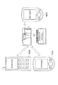
以下、図面を参照して本発明の実施形態を詳細に説明する。図1は、本発明の一実施の形態に係る情報機器システムの概要を示す概念図である。本実施形態の情報機器システムでは、デジタルスチルカメラ101と、PDA端末102A、102A’や携帯電話102Bなどの情報機器102とが、無線通信(例えば、2.45GHz帯を用いたBluetooth(登録商標)や赤外線を用いたIrDA、長波長帯を用いた非接触IC・PHS/携帯電話用通信網など)により通信を行い、相互間でデータのやり取りを行う。
【0012】
デジタルスチルカメラ101は、内部の撮像回路により、情報機器102についての固有の情報を撮像し、この撮像した画像を分析して内部のデータ記憶手段に保存する。そして、このデータ記憶手段に登録された機器との無線通信を受け付け、登録されていない機器との通信要求は受付ない様にする事で通信の認証を行う。
【0013】
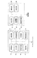
図2は、デジタルスチルカメラ101と情報機器102の内部構成を示すブロック図である。デジタルスチルカメラ101は、撮像回路11と、画像認識回路12と、記憶回路13と、無線通信回路14と、表示回路15とから構成される。情報機器102は、表示回路21と、記憶回路22と、無線通信回路23とから構成される。
【0014】
例えばこの無線通信において情報機器102がマスターとなり、デジタルスチルカメラ101がスレーブとなる通信の場合、情報機器102は、機器自体もしくは機器所有者が独自に備えている特定の情報(固有の情報)を、文字列からなる特定のコードに変換し表示回路21に表示する。
【0015】
デジタルスチルカメラ101は、表示回路21に表示された固有の情報を撮像回路11を用いて撮像し、撮像した固有の情報を画像認識回路12によりデジタルスチルカメラ内部で扱える形式に変換して、記憶回路13に記憶する。
【0016】
このように、撮像動作により機器の関連付けを行うようにしたので、無線通信可能な範囲内で数多く有る機器の中から登録したい機器を探すと言った作業をなくすことができる。
【0017】
この撮像動作を伴う情報機器102の登録を一度行ったのちは、情報機器102内部の無線通信回路23が通信を制御する信号を送った際に、デジタルスチルカメラ101は内部の無線通信回路14を用いて通信を行なう。このとき、登録されていない機器には無線通信のエラーコードを送信する事で、自ら機器の所有者が登録した情報機器以外からの無線通信信号には応答しないようにすることができ、デジタルスチルカメラ101内部のデータを保護するようになっている。
【0018】
次に、無線通信においてデジタルスチルカメラ101がマスターとなり、情報機器102がスレーブとなる場合について説明する。撮像による登録までは先に述べた実施形態と同じように記憶回路13に登録を行なう。そして、登録された機器の一覧を表示回路15に表示し、表示された一覧の中から任意のものを選択し、無線通信回路14を用いて制御信号を送る方法も考えられる。
【0019】
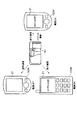
また、デジタルスチルカメラ101がマスターとなる場合には、図3に示すように、認証動作を行う際に通信可能範囲内に存在する情報機器102(PDA端末102A、102A’や携帯電話102B)の表示回路21に固有の情報を表示させる信号を送り、その時点で電源が投入されている情報機器102(図3ではPDA端末102A’と携帯電話102B)については表示回路21に固有の情報を表示する。その際に撮像を行い画像認識を行なうことでボタンを増やすことなく容易に関連付けを行う事が可能となる。
【0020】
撮像による無線通信の認証登録を行うために、情報機器102の表示回路21に機器もしくは機器所有者に固有の情報を表示させる必要があるが、その具体的方法について図4(a)、(b)を参照して説明する。第1の方法では図4(a)に示すように、情報機器102の表示回路21に文字列データを表示し、デジタルスチルカメラ101の画像認識回路12で認識させる方法である。第2の方法は図4(b)に示すように、バーコードデータをデジタルスチルカメラ101の画像認識回路12が認識可能なコードに変換した上で表示回路21に表示し、これをデジタルカメラ101の撮像回路11により撮像し、画像認識回路12で認識する方法である。
【0021】
なお、本発明では、情報機器102が画像を表示し、デジタルスチルカメラ101の撮像回路11による撮像を行なうことにより、無線通信を行う対象となる情報機器102の認証を行っているが、ほぼ同様の構成で情報機器102がスピーカなどの発音手段を有し、デジタルスチルカメラ101などの登録したい側の機器がマイクロフォン等の、集音手段と音声認識手段を有していれば、本発明とほぼ構成を同じくして音声による無線通信機器の認識まで行うことが可能である。
【0022】
図5は、本発明の一実施形態における情報機器システムのブロック図である。デジタルスチルカメラ101は、制御回路10と、撮像回路11と、画像認識回路12と、記憶回路13と、無線通信回路14と、表示回路15と、手動操作回路16と、認証回路17とを具備する。
【0023】
制御回路10は、主にCPUやMPUによって構成され、デジタルスチルカメラ101全体の動作の制御を司る回路である。
【0024】
撮像回路11は、主にデジタルスチルカメラ101の主機能である被写界情報をデジタルデータに変換し、記憶回路13に保存する回路である。ここではCCDやCMOSと言った撮像素子や、撮像素子に被写界の画像を効率良く結像させる光学レンズ、被写体までの距離を測定する測距回路等で構成される。本発明では、撮像回路11は、撮像を行った画像を元に無線通信の認証の登録を行う際にも用いられる。
【0025】
画像認識回路12は、画像処理エンジンなどによって構成され、撮像回路11で撮像されて記憶回路13に保存された被写界情報をもとに、撮影した画像が何を意味するものなのかについて画像処理によって分析を行い、撮像回路11からの入力を制御回路10で扱える形のデータに変換する。
【0026】
記憶回路13は、不揮発性記憶メモリやDRAMによって構成され、デジタルスチルカメラ101が露光動作により取得した被写界情報や、ユーザが機器を使いやすくする為に設定したユーザ情報、撮像、認証動作によって一度登録された、無線通信端末に固有の情報等を保存する。本発明では画像認識回路12が動作する為に、一時的に画像認識回路12が認識を完了するまでの間データを記憶しておく為にも用いられる。
【0027】
無線通信回路14は、BluetoothやIrDA、無線LANなどにおいて用いられる制御ICによって構成され、送信を行いたいデータを通信を行える形式のデータに変換し、対応機器間での無線通信を可能とする回路であり、制御信号の送受信やデータの送受信等に用いられる。本発明の実施形態では無線通信におけるマスタとして機能するがスレーブとして用いられる様にする事も考えられる。
【0028】
表示回路15は、LCDパネルや有機ELシートなどによって構成され、デジタルスチルカメラ101の撮像回路11によって撮像され、記憶回路13に保存された画像や、デジタルスチルカメラ101の設定情報等の表示、ユーザの手動操作の確認の為の表示を行う為などに用いられる。本発明では撮像動作により情報機器を関連付ける際に、実際に登録できた事の確認の際や登録解除の際に情報機器の選択などを行えるようにする為に用いられる。
【0029】
手動操作回路16は、十字入力キーやダイアル、SW等によって構成され、デジタルスチルカメラ101の使用者が所望する動作を機器に入力を行い、制御回路10に送り、ユーザの要求通りにデジタルスチルカメラ101の動作を行う為の回路である。
【0030】
認証回路17は、外部の機器より無線通信回路14に無線通信要求が到着した際に、当該要求に係る情報機器102が既にデジタルスチルカメラ101の記憶回路13に登録されているかどうかを判断する。登録されていない情報機器102からの無線通信要求であればエラーを返し、登録されている情報機器からの無線通信要求であれば無線通信を行う、といった認証動作を行う。
【0031】
次に、情報機器102について説明する。情報機器102は、制御回路20と、表示回路21と、記憶回路22と、無線通信回路23とを具備する。
【0032】
制御回路20は、例えば、CPUやMPU等によって構成され、情報機器102の全体の動作シーケンスを司る制御を行う。
【0033】
表示回路21は、例えば、LCDパネルや有機ELシートなどによって構成され、情報機器102の状態表示や内蔵の記憶回路22の内容や、本発明において通信機器の登録に用いる固有情報記憶回路24内の、機器特有の情報を表示させる為に用いられる。
【0034】
無線通信回路23は、例えば、BluetoothやIrDA、無線LANなどの制御ICによって構成され、送信を行いたいデータを通信を行える形式のデータに変換し、対応機器間での無線通信を可能とする回路であり、制御信号の送受信やデータの送受信等に用いられる。
【0035】
記憶回路22は、例えば、不揮発性メモリやDRAM等によって構成され、使用者が入力した情報や無線通信端末によって取得したデータ等を保存しておく為の回路である。
【0036】
固有情報記憶回路24は、不揮発性メモリなど、データがユーザの操作等によって消失したり、他の機器と競合する事のない記憶媒体によって構成される。情報機器102の電源ONに連動して、固有情報記憶回路24に記録されている機器固有の情報を表示回路21に表示させ登録作業を行う。
【0037】
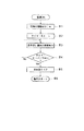
以下に、本発明の特徴となる無線通信の関連付け動作について説明する。図6は、本発明の一実施形態における情報機器102の電源投入時の動作の流れ図である。情報機器102の電源が投入されると、ステップ#1の固有の情報の取りこみ処理に入る。ステップ#1において制御回路20は、製造時もしくは機器所有者によって設定され固有情報記憶回路24に記録されている、機器固有の情報を読み込む処理を行い、機器固有の情報表示の為の準備を行う。次にステップ#2に進む。
【0038】
ステップ#2において、制御回路20は、所定時間でオーバーフローする内蔵のタイマーをスタートさせる。このタイマーの役割としては、電源投入後表示回路21に固有の情報が表示されつづけるのでなく、予め設定された所定時間経過したら表示を停止するための計時を行なう。タイマーをスタートしたらステップ#3に進む。
【0039】
ステップ#3では、表示回路21に無線通信の関連付け処理を行う為の固有情報の表示を行う。この固有情報の表示中に、デジタルスチルカメラ101が当該固有情報を撮像する事で関連付けを行う。そして表示を行ったままステップ#4に進む。
【0040】
ステップ#4では、ステップ#2でスタートさせたタイマーが所定時間経過によりオーバーフローしていないかどうかを確認する。ここで所定時間が経過していなければ引き続き表示しつづけるのでステップ#3に進み、再び表示ルーチンにすすみ、所定時間が経過していればステップ#5に進む。
【0041】
ステップ#5は、情報機器102の電源表示より所定時間経過したので、表示回路21に表示されていた固有の情報を消す為のルーチンである。表示回路21のクリアが完了したらステップ#6に進み、PDAや携帯電話としての動作を行う。
【0042】
上記した図6の処理は、最も簡易化した流れ図であり、毎回電源投入時に機器特有の情報を表示するのではなく、機器の設定により表示しないようにする事も考えられる。また、タイマーのオーバーフローまでステップ#3で、機器固有の情報を表示部21に表示しつづけるが、機器所有者が情報機器102に備えられている手動操作部材を操作した際に、図5のループ処理を抜ける様にして表示動作を短時間で終わらせる事も考えられる。
【0043】
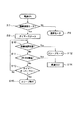
図7は、本発明の一実施形態におけるデジタルスチルカメラ101の電源投入時の動作流れ図である。デジタルスチルカメラ101の電源が投入された場合にはステップ#7に進む。ステップ#7では、デジタルスチルカメラ101の動作モードチェックを行う。無線通信モードに設定されている場合にはステップ#8に進み、その他の静止画撮影モードや動画撮影モード、表示モードの場合にはステップ#9に進んで、それぞれモードに対応した動作を行う。
【0044】
ステップ#8では、無線通信モードを所定時間で終了させる為に、制御回路10は内蔵のタイマーをスタートして、電源オンもしくはモード変更後の時間の計測を行う。無線通信モードのままで待機しつづけると、消費電流が大きくなって電池のエネルギがなくなるので所定時間の計測を行う。タイマーをスタートしたらステップ#10に進む。
【0045】
ステップ#10は、外部から無線通信信号を受信したかどうかをチェックするルーチンであり、外部よりの無線通信信号を受信し、無線通信のスレーブとして動作する場合にはステップ#12に進み、無線通信のスレーブとしての通信を行う。無線信号を受信しなければそのままステップ#11に進む。
【0046】
ステップ#11では手動操作部材からの入力をチェックする。モード変更などの処理があった場合もここで割込みを発生する処理によりこの流れ図を抜けるが、本発明においては、デジタルスチルカメラ101の撮像動作と連動する2R SWの操作が検出されたかどうかを判断し、検出された場合にはステップ#14に進んで関連付け動作を行う。この関連付け動作に関しては、図8を用いて後で詳しく説明を行う事にする。2R SWも他のスイッチも検出されなければステップ#13に進む。
【0047】
ステップ#13では、ステップ#8でスタートしたタイマーが所定時間の経過によりオーバーフローしていないかどうかを確認する。まだ所定時間に達していなければステップ#10に戻り、ステップ#11の無線通信信号待ちと、ステップ#12のSW検出待ちを行う。もしタイマーがオーバーフローしていたらステップ#15に移行し、制御回路10の低消費電力モードに移行し、電池を無駄に消費する事を防ぐスリープモードに移行する。
【0048】
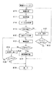
図8は、本発明の一実施形態におけるデジタルスチルカメラの関連付け動作の流れ図である。
【0049】
まずステップ#14で関連付けルーチンが呼ばれると、ステップ#16にてデジタルスチルカメラ101は測光センサや測距センサを用いて被写界情報を測定し、CCDセンサやCMOSセンサで構成される撮像回路11を駆動して撮像動作を行う。この際にユーザは撮像動作を行う光学系を、無線通信を行いたい情報機器102の表示回路21に向けて撮像動作を行う必要がある。そして、撮像動作が完了したらステップ#17に進む。
【0050】
ステップ#17では、ステップ#14の撮像動作によって得られた被写界情報の記憶を行う。デジタルスチルカメラ101の制御回路10は、撮像回路11の出力を以後の分析処理の為に記憶回路13に一時的に記憶させる。そしてステップ#18に進み、データ分析処理を行なう。
【0051】
ステップ#18においてデジタルスチルカメラ101の制御回路10は、画像認識回路12を駆動させて記憶回路13に記憶されている情報機器102の表示回路21に表示される図4に示すような文字情報やバーコード情報の解析を行う。この解析によりデジタルスチルカメラ101が認識できるコードに変換できたかどうかの判断をステップ#19に進み行う。
【0052】
ステップ#19では、デジタルスチルカメラ101の画像認識回路12の出力がデジタルスチルカメラ101の制御回路10で扱えるデータに変換できたかどうかのチェックを行う。情報機器102の表示回路21に表示された機器固有の情報がこの変換により、制御回路10で認識でき、かつ取り扱いできるデータであればステップ#20に進む。情報機器102の表示回路21に何も表示されていなかった場合、もしくは表示されていても関連付けに関係ないコードが表示された場合、または全く関係無いものを撮像した場合にはステップ#21に進む。
【0053】
ステップ#21では、画像認識回路12で認識する事のできなかった記憶回路13に保存されている画像と、エラーメッセージをデジタルスチルカメラ101の表示回路15に表示させる。そしてステップ#22に進む。
【0054】
また、ステップ#22では、認識できなかった事を受けて、もう一度機器登録作業を行うかどうかを、デジタルスチルカメラ101及び情報機器102の使用者にたずねる。デジタルスチルカメラ101及び情報機器102の使用者は、機器登録作業を行うかどうかを手動操作回路16を介してデジタルスチルカメラ101に入力する。
【0055】
機器登録作業をここでいったん止めたい場合には、記憶回路13に一時的に記憶された被写界情報を記憶容量の削減の為に削除してステップ#28に進み、関連付けルーチンを終了する。一方、もう一度機器登録作業を行いたい場合には#16に進む事になる。
【0056】
また、本流れ図では記載していないが、仮に機器登録作業中にデジタルスチルカメラ101の使用者が通常の被写界の撮影動作を行いたいと思い、ステップ#16で撮像動作を行なうことも考えられる。この場合、制御回路10はエラー表示する際に、ステップ#21で撮像した画像を正式に記憶回路13に記憶するかどうかの問いかけを表示回路15に表示させる。使用者はこれに応答して記録を行うかどうかの確認を手動操作回路16により行う。
【0057】
ステップ#20では、ステップ#19にて分析可能と判断された出力データを記憶部13に記憶する処理を行う。そして、ステップ#23に進む。
【0058】
ステップ#23では、ステップ#20で記憶された情報機器102のデータに対して無線通信回路14を駆動して無線通信を行う。無線通信信号の送信が完了したらステップ#24に進む。
【0059】
ステップ#24では、ステップ#23にてデジタルスチルカメラ101より情報機器102に対して行った無線通信に対して応答があるかどうかを確認する。ここでは擬似的に情報機器102の表示部に他の機器の固有の情報を表示させる等の処理を行なう。画像認識回路12が解析した固有の情報を持つ情報機器が近くに存在しない場合、認識させる事は誤認識となるので、情報機器102からの応答があるまで所定時間待機動作を行う。応答が無かった場合にはステップ#25に進み、応答があった場合はステップ#27に進む。
【0060】
ステップ#25では、ステップ#24で無線通信に対する応答を待っていたのに応答が来なかったことを知らせるべくデジタルスチルカメラ101の表示回路15に表示を行う。機器使用者は再びこの無線通信動作による確認を行うかどうかを、手動操作回路16からの入力により選択する。もし、関連付け動作をいったん打ち切る場合はステップ#20で記憶された画像認識回路12の出力データを消去し、ステップ#28に進み関連付け動作を終了する。もう一度再トライしたい場合はステップ#23に戻って無線通信回路14を駆動させ、ステップ#24で応答待機待ちとなる。
【0061】
ステップ#27では、画像認識回路12で得られた情報機器102が近くに存在することが確認されたので、正式に記憶回路13に情報機器102の関連付けを行う。そしてステップ#28に進んで正式に無線通信可能機器として登録を行う。
【0062】
今後、デジタルスチルカメラ101の認証回路17はこの登録を行った機器からの無線通信信号を受信して無線を行えるようにする。登録されて無い機器からの無線信号はエラー信号を送信し応答する事にして、対応機器のみ通信を可能とする。
【0063】
本実施形態では、デジタルスチルカメラ101が無線通信のホスト機器にも、スレーブ機器にもなれる場合の実施形態を説明したが、ホスト機器になれず外部からの信号に対して応答するしか出来ないターゲット機器の場合、ステップ#23の無線通信動作が行えない事になる。その場合、少しセキュリティの面で上記の実施例より弱くなってしまう事になるが、ステップ#20で記憶した分析されたデータをそのまま記憶回路に対応機器として保存し、その機器だけ無線通信を行うことも考えられる。
【0064】
今まで述べてきた実施形態では、情報機器102は、電源投入時に機器固有の情報を表示部21に毎回表示、もしくは設定により電源投入時に表示回路21に機器固有の情報を表示させるようにしたが、デジタルスチルカメラ101が、機器固有の情報表示命令を送信できる場合には、以下のような方法により情報機器102の表示回路21に表示させる。
【0065】
図9は、本発明の一実施形態における情報機器の無線通信割込み動作の流れ図である。
【0066】
情報機器102に電源が入っている状態で、外部より無線通信信号を受信し割込み動作が発生した場合にはステップ#29に進む。ステップ#29では、情報機器102の記憶回路22に既に関連付けられた機器からの無線通信信号かどうかのチェックを行う。もし既に無線通信機器として登録されている機器からの通信信号であれば、ステップ#30に進んで通常の無線通信動作を行う。もし、まだ登録されていない機器からの通信信号である場合にはステップ#31に進む。
【0067】
ステップ#31では、無線通信を要求している機器の無線IPを一時的に記憶回路22に保存する。そして、ステップ#32に進む。
【0068】
ステップ#32では、外部の機器からの無線信号かどうかを確認し、機器固有の情報を表示する命令であればステップ#33に進む。もし、他のデータ送信命令等であった場合には、登録されていない機器に対してデータを送信するのはセキュリティ上問題があるので、ステップ#34に進み通信エラー処理を行う。通信エラー処理は送られてきた機器の無線IPに対して通信エラー信号を送るとともに表示回路21に無線通信NGを表示させる処理である。これにより無線通信の失敗が確認されて情報機器102は無線通信割込み処理を抜け、通常動作に移る。
【0069】
ステップ#33では、情報機器102の固有情報記憶回路24に保存されている、機器製造時に設定される無線IPや機器所有者特有の情報を制御回路20が読み出す処理を行う。この情報を正常に取り込めた場合にはステップ#35に進む。
【0070】
ステップ#35では、表示回路21に固有の情報を表示しておく為の所定時間を設定するタイマーをスタートさせる処理を行う。そしてタイマーをスタートしたらステップ#36に進む。
【0071】
ステップ#36では、制御回路20はステップ#33で読み出した機器固有の情報を表示回路21に表示させる処理を行う。そしてステップ#37に進み、ステップ#35でスタートさせたタイマーがオーバーフローするまで、表示回路21に機器固有の情報を表示しつづける処理を行う。タイマーがオーバーフローしたらステップ#38に進む。
【0072】
ステップ#38では、表示回路21に表示されていた機器固有の情報をクリアする処理を行う。このクリア動作までの間に、関連付けを行いたいデジタルスチルカメラ101はステップ#16の撮像動作からステップ#20までを実行することになる。そしてそのまま#39に進む。
【0073】
ステップ#39では無線通信信号を受信するまでの所定時間を設定するタイマーをスタートさせる。そしてステップ#40に進む。ステップ#40では、関連付けを行いたいデジタルスチルカメラ101からの無線通信信号が到来したかどうかの確認を行う。もし無線通信信号を受信していなければステップ#41に進み、ステップ#39でスタートさせたタイマーがオーバーフローするまで、ステップ#40とステップ#41の間でループを回り、所定時間の経過後、ステップ#39のタイマーがオーバーフローしたらステップ#44に進み割込み処理を終える。もし、タイマーがオーバーフローする前に無線通信信号を受信したら、ステップ#42に進む。
【0074】
ステップ#42では、ステップ#31で保存した固有情報表示命令を送ってきた情報機器と、今回の無線通信信号を送ってきた機器の無線IPが一致しているかどうかを確認する処理を行う。これにより、無線IPの一致が確認できたら、機器を登録する為にステップ#43に進み、もし一致しなければ、登録NGとなるのでステップ#44に進んで無線割込処理を終える。
【0075】
ステップ#43では無線機器の関連付け動作を行う。情報機器内の記憶回路22にステップ#31とステップ#42の処理で一致した無線機器の無線IPを保存する。これにより、今後情報機器102は、ステップ#29で関連付けされた機器からの通信かどうかを判別する事で、安全に無線通信をおこなう事が出来る。
【0076】
以上が、本発明における一実施形態における無線通信機器の登録処理である。
【0077】
(付記)
1. 近距離型無線通信手段を有するデジタルスチルカメラと、
上記デジタルスチルカメラと所定距離内で近距離型無線通信を行う事の出来る情報機器とを含む情報機器システムにおいて、
上記デジタルスチルカメラは、
上記情報機器についての固有の情報を撮像する撮像手段と、
上記撮像手段により撮像された固有の情報を所定の形式に変換する画像認識手段と、
上記画像認識手段より変換された固有の情報を記憶するための記憶手段と、
上記記憶手段に記憶された固有の情報に基づいて、情報機器との通信の可否を決定する認証手段と、
を具備することを特徴とする情報機器システム。
【0078】
2. 上記情報機器は、機器自体もしくは機器所有者に固有の情報を記憶する情報記憶手段と、当該固有の情報を表示する表示手段とを有し、
近距離型無線通信を行う相手となる機器の登録時に、上記固有の情報を上記上記記憶手段から読み出して上記表示手段に表示させ、表示された固有の情報を上記デジタルスチルカメラの撮像手段により撮像することにより登録を行なうことを特徴とする1.に記載の情報機器システム。
【0079】
3. 上記固有の情報は、機器の製造時に割り当てられる固有のアドレスであることを特徴とする1.に記載の情報機器システム。
【0080】
4. 上記表示手段は、上記情報機器の電源投入の際に、上記固有の情報を所定時間表示することを特徴とする2.に記載の情報機器システム。
【0081】
5. 上記表示手段は、上記情報機器が電源投入されている状態の時に、上記デジタルスチルカメラからの無線通信信号の受信に従って、上記固有の情報を所定時間表示することを特徴とする2.に記載の情報機器システム。
【0082】
6. 上記デジタルスチルカメラは無線通信スレーブとなる機器であり、予め内蔵のデータ記憶部に固有情報が登録された情報機器の無線通信信号のみ無線通信動作を行う事を特徴とした1.に記載の情報機器システム。
【0083】
7. 上記デジタルスチルカメラは、被写界情報や操作の内容を確認する状態表示手段を有する無線通信におけるマスターとなる機器であり、予め内蔵のデータ記憶部に登録された情報機器を上記状態表示手段により選択し、選択された機器に対して通信の信号を送信することを特徴とする1.に記載の情報機器システム。
【0084】
【発明の効果】
本発明によれば、近くに複数の同様の通信規格の機器が多く存在する場合であっても容易にデジタルスチルカメラと情報機器の動作を関連付ける事が出来るようになる。
【図面の簡単な説明】
【図1】本発明の一実施の形態に係る情報機器システムの概要を示す概念図である。
【図2】デジタルスチルカメラ101と情報機器102の内部構成を示すブロック図である。
【図3】本発明の関連付け動作を行なう一実施形態の概念図である。
【図4】本発明における機器固有の情報を表示させる一実施形態を説明するための図である。
【図5】本発明の一実施形態における情報機器システムのブロック図である。
【図6】本発明の一実施形態における情報機器の電源投入時の動作の流れ図である。
【図7】本発明の一実施形態におけるデジタルスチルカメラの電源投入時の動作流れ図である。
【図8】本発明の一実施形態におけるデジタルスチルカメラの関連付け動作の流れ図である。
【図9】本発明の一実施形態における情報機器の無線通信割込み動作の流れ図である。
【符号の説明】
10 制御回路
11 撮像回路
12 画像認識回路
13 記憶回路
14 無線通信回路
15 表示回路
16 手動操作回路
17 認証回路
20 制御回路
21 表示回路
22 記憶回路
23 無線通信回路
24 固有情報記憶回路
101 デジタルスチルカメラ
102A、102A’ PDA端末
102B 携帯電話[0001]
BACKGROUND OF THE INVENTION
The present invention relates to an information equipment system. And information equipment It is about.
[0002]
[Prior art]
JP 2001-142 A 77 Is stored in each information storage unit in an information device such as a digital still camera having a wireless communication means and a portable wireless communication terminal represented by a mobile phone or the like. Memory It is disclosed that communication is ensured by comparing and comparing with owner information such as a password and the like.
[0003]
[Problems to be solved by the invention]
In the conventional method, when initial communication between information devices having wireless communication means is ensured, wireless communication is first performed using wireless communication means such as Bluetooth (registered trademark), and the same owner-specific information is obtained. It is configured to be able to communicate by searching for and checking the devices in each information storage unit. However, due to the widespread use of wireless communication terminals, when there are many wireless communication terminals in the vicinity, it takes a very long time to perform an authentication operation on each of them.
[0004]
Further, it can be said that it is difficult for the user to input a unique IP address used for communication in order to register a device to be communicated on the camera side with few manual operation members.
[0005]
The present invention has been made paying attention to such a problem, and its object is as follows. Information device system and information device capable of easily registering devices to communicate with Is to provide.
[0006]
[Means for Solving the Problems]
To achieve the above object, a first aspect of the present invention Related information equipment system Is wireless In an information device system including a plurality of information devices having a communication function, among the plurality of information devices, an information device having a display circuit capable of displaying information unique to the device itself or the device owner, and an imaging circuit An information device having circuit An information device having an image can capture the unique information displayed on the device having the display circuit, and register the unique information of the target device by analyzing the captured image. Thus, prior to performing the registration process, a signal for displaying each unique information is transmitted to an information device existing within a communicable range. .
[0007]
The second aspect of the present invention Related information equipment system In the first aspect Information equipment system In the display circuit, character string data or bar code data is displayed.
[0008]
The third aspect of the present invention Related information equipment system The first aspect Related information equipment system The unique information is address data for communication or password data.
[0009]
The fourth aspect of the present invention Related information equipment system An image pickup circuit for picking up information unique to the other information device displayed on the display circuit of the other information device, and analyzing the unique information picked up by the image pickup circuit to analyze the other information device. An image recognition circuit for registering unique information of the device, and a communication circuit for communicating with the other information device based on the registered unique information. And the communication circuit outputs a signal instructing the other information device to display the information prior to the imaging operation by the imaging circuit. .
[0010]
DETAILED DESCRIPTION OF THE INVENTION
In the present invention, device-specific information such as an IP address or barcode / password is displayed on the display unit of an information device such as a wireless communication terminal that wants to perform wireless communication, and the camera captures this unique information. To do. The image acquired by this imaging operation is recognized, the unique information is taken in, and the operation of the camera and the information device is associated. With such association, there is no need to provide a special operation member necessary for authentication on the camera side to increase the size of the device, and wireless communication is not performed at the time of registration of the wireless communication terminal, so there are many devices in the vicinity. Even in this case, the wireless communication terminal can be easily registered without taking time for authentication.
[0011]
Hereinafter, embodiments of the present invention will be described in detail with reference to the drawings. FIG. 1 is a conceptual diagram showing an outline of an information equipment system according to an embodiment of the present invention. In the information device system of the present embodiment, the
[0012]
The
[0013]
FIG. 2 is a block diagram showing the internal configuration of the digital
[0014]
For example, in the case of communication in which the
[0015]
The
[0016]
As described above, since the devices are associated with each other by the imaging operation, it is possible to eliminate the task of searching for a device to be registered from among a large number of devices within a wireless communication range.
[0017]
After registering the
[0018]
Next, a case where the digital still
[0019]
When the digital
[0020]
In order to perform authentication registration of wireless communication by imaging, it is necessary to display information specific to the device or device owner on the
[0021]
In the present invention, the
[0022]
FIG. 5 is a block diagram of an information equipment system according to an embodiment of the present invention. The digital
[0023]
The
[0024]
The
[0025]
The
[0026]
The
[0027]
The
[0028]
The
[0029]
The
[0030]
When a wireless communication request arrives at the
[0031]
Next, the
[0032]
The
[0033]
The
[0034]
The
[0035]
The
[0036]
The unique
[0037]
Hereinafter, an association operation of wireless communication, which is a feature of the present invention, will be described. FIG. 6 is a flowchart of the operation at the time of turning on the
[0038]
In
[0039]
In step # 3, unique information for performing a wireless communication association process is displayed on the
[0040]
In
[0041]
[0042]
The process of FIG. 6 described above is the most simplified flowchart, and it may be possible not to display device-specific information every time the power is turned on but to display it by setting the device. Further, in step # 3 until the timer overflows, the device-specific information is continuously displayed on the
[0043]
FIG. 7 is an operation flowchart when the digital
[0044]
In
[0045]
[0046]
In
[0047]
In
[0048]
FIG. 8 is a flowchart of the association operation of the digital still camera according to the embodiment of the present invention.
[0049]
First, when the association routine is called in
[0050]
In
[0051]
In
[0052]
In
[0053]
In
[0054]
In
[0055]
If it is desired to stop the device registration work here, the scene information temporarily stored in the
[0056]
Although not described in this flowchart, it is assumed that the user of the digital
[0057]
In
[0058]
In
[0059]
In
[0060]
In
[0061]
In
[0062]
In the future, the
[0063]
In this embodiment, the embodiment in which the digital
[0064]
In the embodiment described so far, the
[0065]
FIG. 9 is a flowchart of the wireless communication interrupt operation of the information device according to the embodiment of the present invention.
[0066]
If the wireless communication signal is received from the outside while the
[0067]
In
[0068]
In
[0069]
In
[0070]
In
[0071]
In
[0072]
In
[0073]
In
[0074]
In
[0075]
In
[0076]
The above is the registration processing of the wireless communication device in one embodiment of the present invention.
[0077]
(Appendix)
1. A digital still camera having a short-range wireless communication means;
In an information equipment system including the digital still camera and an information equipment capable of performing short-range wireless communication within a predetermined distance,
The digital still camera
Imaging means for imaging unique information about the information device;
Image recognition means for converting unique information captured by the imaging means into a predetermined format;
Storage means for storing unique information converted by the image recognition means;
An authentication unit that determines whether communication with the information device is possible based on the unique information stored in the storage unit;
An information equipment system comprising:
[0078]
2. The information device has information storage means for storing information unique to the device itself or the device owner, and display means for displaying the unique information,
When registering a device to be a partner for short-range wireless communication, the unique information is read from the storage means and displayed on the display means, and the displayed unique information is imaged by the imaging means of the digital still camera. It is characterized in that registration is performed. The information equipment system described in 1.
[0079]
3. The unique information is a unique address assigned at the time of manufacturing the device. The information equipment system described in 1.
[0080]
4). The display means displays the unique information for a predetermined time when the information device is turned on. The information equipment system described in 1.
[0081]
5. The display means displays the specific information for a predetermined time in accordance with reception of a wireless communication signal from the digital still camera when the information device is powered on. The information equipment system described in 1.
[0082]
6). The digital still camera is a device serving as a wireless communication slave, and performs a wireless communication operation only on a wireless communication signal of an information device in which unique information is registered in advance in a built-in data storage unit. The information equipment system described in 1.
[0083]
7). The digital still camera is a master device in wireless communication having state display means for confirming object scene information and operation contents, and information devices registered in a built-in data storage unit in advance are displayed by the state display means. 1. Select and transmit a communication signal to the selected device. The information equipment system described in 1.
[0084]
【The invention's effect】
According to the present invention, it is possible to easily associate the operations of a digital still camera and an information device even when there are many devices having a similar communication standard nearby.
[Brief description of the drawings]
FIG. 1 is a conceptual diagram showing an outline of an information equipment system according to an embodiment of the present invention.
FIG. 2 is a block diagram showing an internal configuration of the digital
FIG. 3 is a conceptual diagram of an embodiment for performing an association operation of the present invention.
FIG. 4 is a diagram for explaining an embodiment of displaying device-specific information in the present invention.
FIG. 5 is a block diagram of an information equipment system according to an embodiment of the present invention.
FIG. 6 is a flowchart of the operation at the time of power-on of the information device according to the embodiment of the present invention.
FIG. 7 is an operation flowchart when the digital still camera according to the embodiment of the present invention is turned on.
FIG. 8 is a flowchart of an association operation of a digital still camera according to an embodiment of the present invention.
FIG. 9 is a flowchart of the wireless communication interrupt operation of the information device according to the embodiment of the present invention.
[Explanation of symbols]
10 Control circuit
11 Imaging circuit
12 Image recognition circuit
13 Memory circuit
14 Wireless communication circuit
15 Display circuit
16 Manual operation circuit
17 Authentication circuit
20 Control circuit
21 Display circuit
22 Memory circuit
23 Wireless communication circuit
24 Unique information storage circuit
101 digital still camera
102A, 102A 'PDA terminal
102B mobile phone
Claims (4)
上記複数の情報機器の中には、機器自体もしくは機器所有者に固有の情報を表示可能な表示回路を有する情報機器、及び、撮像回路を有する情報機器が含まれており、
上記撮像回路を有する情報機器は、上記表示回路を有する機器にて表示されている上記固有情報を撮像し、この撮像した画像を分析することによって対象機器の固有情報を登録可能であって、該登録処理を行うのに先立って通信可能な範囲に存在する情報機器に対して各々の固有情報を表示させる信号を送信することを特徴とする情報機器システム。 In an information equipment system including a plurality of information equipment having a wireless communication function,
Among the plurality of information devices, an information device having a display circuit capable of displaying information unique to the device itself or the device owner, and an information device having an imaging circuit are included.
Information device having the imaging circuit captures the specific information displayed by the device having the display circuit, I registrable der specific information of the target device by analyzing the captured image, An information device system, wherein a signal for displaying each unique information is transmitted to an information device existing within a communicable range prior to performing the registration process .
上記撮像回路で撮像した上記固有情報を分析して、上記他の情報機器の固有情報を登録する画像認識回路と、
上記登録した固有情報に基づいて、上記他の情報機器と通信する通信回路と、
を具備しており、
上記通信回路は、上記撮像回路による撮像動作に先立って上記他の情報機器に対して上記情報を表示するように指示する信号を出力することを特徴とする情報機器。An imaging circuit for imaging information unique to the other information device displayed on the display circuit of the other information device;
An image recognition circuit that analyzes the unique information imaged by the imaging circuit and registers unique information of the other information device;
Based on the registered unique information, a communication circuit that communicates with the other information device,
It has
Prior to the imaging operation by the imaging circuit, the communication circuit outputs a signal instructing the other information device to display the information.
Priority Applications (1)
| Application Number | Priority Date | Filing Date | Title |
|---|---|---|---|
| JP2001342187A JP4036635B2 (en) | 2001-11-07 | 2001-11-07 | Information device system and information device |
Applications Claiming Priority (1)
| Application Number | Priority Date | Filing Date | Title |
|---|---|---|---|
| JP2001342187A JP4036635B2 (en) | 2001-11-07 | 2001-11-07 | Information device system and information device |
Publications (3)
| Publication Number | Publication Date |
|---|---|
| JP2003143457A JP2003143457A (en) | 2003-05-16 |
| JP2003143457A5 JP2003143457A5 (en) | 2005-07-07 |
| JP4036635B2 true JP4036635B2 (en) | 2008-01-23 |
Family
ID=19156084
Family Applications (1)
| Application Number | Title | Priority Date | Filing Date |
|---|---|---|---|
| JP2001342187A Expired - Fee Related JP4036635B2 (en) | 2001-11-07 | 2001-11-07 | Information device system and information device |
Country Status (1)
| Country | Link |
|---|---|
| JP (1) | JP4036635B2 (en) |
Families Citing this family (7)
| Publication number | Priority date | Publication date | Assignee | Title |
|---|---|---|---|---|
| JP4312642B2 (en) * | 2004-03-31 | 2009-08-12 | 富士フイルム株式会社 | Wireless LAN transmitter and control method thereof |
| JP2007274567A (en) * | 2006-03-31 | 2007-10-18 | Olympus Imaging Corp | Information apparatus system and electronic camera used for information apparatus system |
| JP4914182B2 (en) | 2006-11-15 | 2012-04-11 | キヤノン株式会社 | Data processing apparatus, method for controlling data processing apparatus, and computer program for causing computer to execute the control method |
| JP5214279B2 (en) | 2008-03-04 | 2013-06-19 | オリンパス株式会社 | Information processing terminal, terminal selection system |
| US8839379B2 (en) * | 2010-10-26 | 2014-09-16 | Cisco Technology, Inc. | Using an image to provide credentials for service access |
| WO2011144025A2 (en) * | 2011-05-18 | 2011-11-24 | 华为终端有限公司 | Networking method, server end device, client end device and network system |
| JP2013143616A (en) | 2012-01-10 | 2013-07-22 | Nec Access Technica Ltd | Radio communication terminal, information provision medium, access point, radio communication method, and program |
-
2001
- 2001-11-07 JP JP2001342187A patent/JP4036635B2/en not_active Expired - Fee Related
Also Published As
| Publication number | Publication date |
|---|---|
| JP2003143457A (en) | 2003-05-16 |
Similar Documents
| Publication | Publication Date | Title |
|---|---|---|
| US7403510B1 (en) | Communication terminal apparatus, communication method thereof, and connected destination selection method in wireless LAN | |
| US7164438B2 (en) | Electronic pickup camera and control method of electronic pickup camera | |
| JP6004752B2 (en) | COMMUNICATION DEVICE, ITS CONTROL METHOD, PROGRAM | |
| US7602420B2 (en) | Image capture apparatus, method for controlling the same and computer program | |
| US20070109420A1 (en) | Electronic pickup camera and control method of electronic pickup camera | |
| JP6115159B2 (en) | Image forming apparatus and log management system | |
| JP2002335344A5 (en) | ||
| JP2007116474A (en) | Camera system | |
| CN106356060A (en) | Voice communication method and device | |
| KR20160004930A (en) | Communication apparatus, terminal apparatus, control methods thereof, and computer-readable storage medium | |
| JP6553986B2 (en) | Communication device, control method therefor, program | |
| JP4597583B2 (en) | Data transmission device, data reception device, communication system, control program for data transmission device, control program for data reception device, and computer-readable recording medium | |
| JP6029292B2 (en) | COMMUNICATION DEVICE, COMMUNICATION METHOD, AND PROGRAM | |
| JP4174208B2 (en) | Information processing terminal and information processing method | |
| JP4036635B2 (en) | Information device system and information device | |
| JP2009206774A (en) | System and device for transmitting image, and control method | |
| JP6399854B2 (en) | COMMUNICATION DEVICE, COMMUNICATION DEVICE CONTROL METHOD, PROGRAM | |
| JP4818001B2 (en) | Imaging apparatus, control method thereof, and program | |
| JP2007166660A (en) | Information processing terminal and information processing method | |
| JP2003152713A (en) | Method for authenticating communication opposite party, information communication system, and control program | |
| WO2017092039A1 (en) | Method, apparatus and equipment for providing and obtaining location information | |
| JP6528931B2 (en) | IMAGE PROCESSING SYSTEM, IMAGE PROCESSING DEVICE, REMOTE CONTROL METHOD, AND REMOTE CONTROL PROGRAM | |
| JP5031589B2 (en) | Information processing apparatus, information processing apparatus control method, and program | |
| JP6747486B2 (en) | Device control system, image processing device, device control method, and device control program | |
| JP2012058473A (en) | Position information acquisition device, imaging device, and control method for them |
Legal Events
| Date | Code | Title | Description |
|---|---|---|---|
| A521 | Request for written amendment filed |
Free format text: JAPANESE INTERMEDIATE CODE: A523 Effective date: 20041108 |
|
| A621 | Written request for application examination |
Free format text: JAPANESE INTERMEDIATE CODE: A621 Effective date: 20041108 |
|
| A977 | Report on retrieval |
Free format text: JAPANESE INTERMEDIATE CODE: A971007 Effective date: 20070614 |
|
| A131 | Notification of reasons for refusal |
Free format text: JAPANESE INTERMEDIATE CODE: A131 Effective date: 20070619 |
|
| A521 | Request for written amendment filed |
Free format text: JAPANESE INTERMEDIATE CODE: A523 Effective date: 20070820 |
|
| TRDD | Decision of grant or rejection written | ||
| A01 | Written decision to grant a patent or to grant a registration (utility model) |
Free format text: JAPANESE INTERMEDIATE CODE: A01 Effective date: 20071023 |
|
| A61 | First payment of annual fees (during grant procedure) |
Free format text: JAPANESE INTERMEDIATE CODE: A61 Effective date: 20071030 |
|
| FPAY | Renewal fee payment (event date is renewal date of database) |
Free format text: PAYMENT UNTIL: 20101109 Year of fee payment: 3 |
|
| FPAY | Renewal fee payment (event date is renewal date of database) |
Free format text: PAYMENT UNTIL: 20101109 Year of fee payment: 3 |
|
| FPAY | Renewal fee payment (event date is renewal date of database) |
Free format text: PAYMENT UNTIL: 20111109 Year of fee payment: 4 |
|
| FPAY | Renewal fee payment (event date is renewal date of database) |
Free format text: PAYMENT UNTIL: 20111109 Year of fee payment: 4 |
|
| FPAY | Renewal fee payment (event date is renewal date of database) |
Free format text: PAYMENT UNTIL: 20121109 Year of fee payment: 5 |
|
| FPAY | Renewal fee payment (event date is renewal date of database) |
Free format text: PAYMENT UNTIL: 20131109 Year of fee payment: 6 |
|
| S531 | Written request for registration of change of domicile |
Free format text: JAPANESE INTERMEDIATE CODE: R313531 |
|
| R350 | Written notification of registration of transfer |
Free format text: JAPANESE INTERMEDIATE CODE: R350 |
|
| LAPS | Cancellation because of no payment of annual fees |