JP4035257B2 - Image processing apparatus, image processing method, and computer-readable storage medium - Google Patents
Image processing apparatus, image processing method, and computer-readable storage medium Download PDFInfo
- Publication number
- JP4035257B2 JP4035257B2 JP09759099A JP9759099A JP4035257B2 JP 4035257 B2 JP4035257 B2 JP 4035257B2 JP 09759099 A JP09759099 A JP 09759099A JP 9759099 A JP9759099 A JP 9759099A JP 4035257 B2 JP4035257 B2 JP 4035257B2
- Authority
- JP
- Japan
- Prior art keywords
- image data
- watermark information
- motion
- circuit
- image
- Prior art date
- Legal status (The legal status is an assumption and is not a legal conclusion. Google has not performed a legal analysis and makes no representation as to the accuracy of the status listed.)
- Expired - Fee Related
Links
- 238000003672 processing method Methods 0.000 title claims description 8
- 239000013598 vector Substances 0.000 claims description 18
- 238000000034 method Methods 0.000 claims description 16
- 238000013139 quantization Methods 0.000 claims description 13
- 230000008569 process Effects 0.000 claims description 6
- 238000004590 computer program Methods 0.000 claims description 2
- 230000001131 transforming effect Effects 0.000 claims 2
- 230000000694 effects Effects 0.000 description 21
- 238000007906 compression Methods 0.000 description 17
- 230000006835 compression Effects 0.000 description 17
- 238000001514 detection method Methods 0.000 description 17
- 238000010586 diagram Methods 0.000 description 17
- 238000006243 chemical reaction Methods 0.000 description 10
- 230000006870 function Effects 0.000 description 10
- 238000000926 separation method Methods 0.000 description 6
- 230000006866 deterioration Effects 0.000 description 4
- 230000009466 transformation Effects 0.000 description 4
- 230000015556 catabolic process Effects 0.000 description 3
- 238000006731 degradation reaction Methods 0.000 description 3
- 230000008859 change Effects 0.000 description 2
- 230000002457 bidirectional effect Effects 0.000 description 1
- 230000000903 blocking effect Effects 0.000 description 1
- 238000004891 communication Methods 0.000 description 1
- 238000013144 data compression Methods 0.000 description 1
- 230000003292 diminished effect Effects 0.000 description 1
- 238000003780 insertion Methods 0.000 description 1
- 230000037431 insertion Effects 0.000 description 1
- 238000007726 management method Methods 0.000 description 1
- 230000003287 optical effect Effects 0.000 description 1
- 230000004044 response Effects 0.000 description 1
Images


Classifications
-
- G—PHYSICS
- G06—COMPUTING; CALCULATING OR COUNTING
- G06T—IMAGE DATA PROCESSING OR GENERATION, IN GENERAL
- G06T1/00—General purpose image data processing
- G06T1/0021—Image watermarking
- G06T1/0085—Time domain based watermarking, e.g. watermarks spread over several images
-
- H—ELECTRICITY
- H04—ELECTRIC COMMUNICATION TECHNIQUE
- H04N—PICTORIAL COMMUNICATION, e.g. TELEVISION
- H04N19/00—Methods or arrangements for coding, decoding, compressing or decompressing digital video signals
- H04N19/46—Embedding additional information in the video signal during the compression process
- H04N19/467—Embedding additional information in the video signal during the compression process characterised by the embedded information being invisible, e.g. watermarking
-
- G—PHYSICS
- G06—COMPUTING; CALCULATING OR COUNTING
- G06T—IMAGE DATA PROCESSING OR GENERATION, IN GENERAL
- G06T2201/00—General purpose image data processing
- G06T2201/005—Image watermarking
- G06T2201/0052—Embedding of the watermark in the frequency domain
-
- G—PHYSICS
- G06—COMPUTING; CALCULATING OR COUNTING
- G06T—IMAGE DATA PROCESSING OR GENERATION, IN GENERAL
- G06T2201/00—General purpose image data processing
- G06T2201/005—Image watermarking
- G06T2201/0061—Embedding of the watermark in each block of the image, e.g. segmented watermarking
Description
【0001】
【発明の属する技術分野】
本発明は、画像データに透かし情報を埋め込む画像処理装置、画像処理方法及び画像処理プログラムが記憶されたコンピュータ読み取り可能な記録媒体に関するものである。
【0002】
【従来の技術】
従来からの画像記録/再生装置としては、アナログ映像信号を磁気テープに記録するビデオテープレコーダがあるが、複写を繰り返すと画像劣化もあり、不正利用などの著作権問題もそれほどクローズアップされてこなかった。
これに対して、映像信号をデジタル化し、時には圧縮符号化するなどを施したデジタル画像データは、取り扱いが容易であり、磁気テープに記録するデジタルVTRに記録できるばかりでなく、コンピュータの記憶装置に記憶したり、通信回線を介して伝送できたりする。このデジタル化された画像データは、記録したり伝送したりしても画像の劣化がほとんどないため、不正流用が懸念されている。
【0003】
この不正流用を防ぐ方法として、画像データの著作権者、発信元、管理番号、流通経路等々のID情報データとしてのデジタル透かし(ウォーターマーキング)を画像に入れることが知られている。デジタル透かしとは、画像を見るユーザーからは解らないように、こっそりと透かし情報を画像に混入させ、不正流用された画像の流出元や径路を、後から確認できるようにするものである。この場合、透かし情報を入れることによる画像の劣化を極力抑えることと、画像から透かしだけを抜き取ることができないように混入すること、また透かし情報を入れることによってデータ量が大幅に増加するのを防ぐこと等が重要になってくる。
【0004】
動画像にデジタル透かしを入れる場合は、フレーム毎に透かし情報を混入するとそのデータ量が膨大になるため、一部のフレームのみに入れる方式が提案されている。ただし、あまり透かしを入れるフレーム間隔を広げすぎると、動画像の一部を不正流用された場合の抑止効果が薄れてしまう。
【0005】
【発明が解決しようとする課題】
上述のように、動画像の一部のフレームにデジタル透かしを入れる場合、数フレームに渡って画像が変化しない部分にデジタル透かしを入れると、前後フレームと比較することで、画像に変化が無いにも関わらずデータが変化しているために、デジタル透かしが入っていることが明らかになってしまうばかりか、デジタル透かしの位置までも明らかになってしまう問題があった。それ故に、そのフレームだけを抜くなど、透かしだけを抜き取ることも容易になってしまう。
【0006】
上述したような背景から本願発明の一つの目的は、透かし情報の有無やその場所が明らかになるのを防ぐとともに、透かし情報を入れることによる画像の劣化及びデータ量の増加を抑え、かつ、埋め込まれた透かし情報に対する攻撃耐性を有する画像処理装置、画像処理方法及びその画像処理プログラムが記憶されたコンピュータ読み取り可能な記録媒体を提供することを目的としている。
【0007】
【課題を解決するための手段】
本発明の画像処理装置は、画像データを入力する入力手段と、前記画像データの動きを判定する動き判定手段と、前記動き判定手段において、動き有りと判定された画像データを選択する選択手段と、前記選択された画像データに基づいた情報データに透かし情報を重畳する重畳手段とを有し、前記情報データは、直交変換され、量子化された画像データ、または、動きベクトルデータであり、前記重畳手段は、前記動き判定手段で、動き有りと判定されなかった画像データに対しては、透かし情報を重畳しないことを特徴とする。
【0008】
また、本発明の画像処理方法は、画像データを入力する入力工程と、前記画像データの動きを判定する動き判定工程と、前記動き判定工程において、動き有りと判定された画像データを選択する選択工程と、前記選択された画像データに基づいた情報データに透かし情報を重畳する重畳工程とを有し、前記情報データは、直交変換され、量子化された画像データ、または、動きベクトルデータであり、前記重畳工程は、前記動き判定工程で、動き有りと判定されなかった画像データに対しては、透かし情報を重畳しないことを特徴とする。
【0009】
また、本発明のコンピュータ読み取り可能な記憶媒体は、本発明の画像処理方法の各工程をコンピュータに実行させるためのコンピュータプログラムを格納することを特徴とする。
【0010】
【発明の実施の形態】
以下、図面を参照しながら本発明の第1の実施例を説明する。
図1は、本発明を動画像を記録再生可能なビデオカメラに適用した場合の第1の実施例を構成を示すブロック図である。
図1において、撮影レンズ100を通してCCD(charge coupled device)等の撮像素子101に結像された被写体像は電気信号に変換され、カメラ信号処理回路102で所定の信号処理を行うことで、デジタル画像データに変換される。前記デジタル画像データは、圧縮符号化回路103で後述する圧縮符号化処理されて、記録再生回路104により記録媒体105に記録される。尚、記録媒体105としてはハードディスク、メモリカード、ビデオテープ等を使用すればよい。
【0011】
透かし情報発生回路106は、原著作権者、編集隣接著作権者、及び利用者情報等の利権関係とか、発信元や流通経路を明確にするための透かし情報を発生する回路であり、これらの透かし情報は操作部107を操作することにより作成することができる。
透かし情報発生回路106によって発生された透かし情報は、圧縮符号化回路103により符号化処理中に画像データに埋め込まれる。この処理の詳細は後述する。
【0012】
記録媒体105に記録された符号化された画像データは、記録再生回路104により再生され、復号化回路108によって復号処理される。復号処理された画像データは透かし情報分離回路109に入力される。
透かし情報分離回路109では、復号化回路108から出力された画像データから透かし情報を分離処理する。透かし情報分離回路109で処理された画像データは表示器110へ出力され、表示される。また、透かし情報分離回路109は、分離された透かし情報を操作部107に指示に応じて表示器110へ出力する。
【0013】
つまり、透かし情報分離回路109では、透かし情報すべてを表示器110へ供給して表示させることもできるし、操作部107の指示により透かし情報の中で必要な情報(たとえば、著作者情報)だけを表示器110へ供給して表示させることもできる。更に、透かし情報を表示器110へ全く供給しないようにし、透かし情報を表示器110に表示させないこともできる。
表示器110では、透かし情報分離回路109から透かし情報が供給された時は、前記透かし情報を画像データと共にモニタに表示する。
【0014】
ここで、表示器110の表示例を図2に示す。
図2(a)は、文字情報で埋め込まれた透かし情報のうち、原著作者情報をオンスクリーン表示した例である。この例では、文字情報なので、表示器110内のキャラクタジェネレータを用いて表示文字を作り出している。
図2(b)は、透かし情報が図2(a)のように文字情報ではなく、画像情報として埋め込まれていた場合で、この例では原著作者情報を画像に重ねて表示した例である。
図2(c)は、この映像が、どの流通経路で配布されたかを表示する例である。この例では、TVのオンエアで配布されたことを表している。
図2(d)は、透かし情報をオフにした時の表示例である。
【0015】
次に、圧縮符号化回路103の詳細を図3を参照しながら説明する。図3は、第1の実施例の圧縮符号化回路103の詳細ブロック図である。
図3において、カメラ信号処理回路102から圧縮符号化回路103に入力された画像データは、ブロック分割回路201により水平8画素、垂直8画素で構成されるブロックに分割され、ブロック化された画像データは動き検出回路206と加算器202とに供給される。
【0016】
動き検出回路206では、ブロック単位で画像データの動きを判定する。図4に示すように、現在のフレーム(kフレーム)とひとつ前のフレーム(k−1フレーム)とで、ブロックデータの比較を行ってブロック単位での画像データの動きを判定している。ここでは、ブロック単位で現フレームと前フレームとの差分値を計算し、その差分値に応じて現ブロックの動きを判定している。つまり、差分値が大きければ動き有りと判定し、差分値が小さければ動き無しと判定する。
【0017】
動き検出回路206で、動き有りと判定された図5に示すようなブロックは、ブロック選択回路207で選択される。そして、その動き有りと判定されたブロックに対して、透かし情報発生回路106で発生された透かし情報が、加算器202を介して画像データに重畳される。
但し、ブロック選択回路207は、フレームカウンタ208に従って所定のフレーム間隔を目安に、かつ所定数のブロックに動きが検出されたフレームに対してのみ透かし情報を埋め込むように制御している。すべてのフレームの画像データに透かし情報を重畳するのではなく、固定のフレーム間隔で、或いはランダムなフレーム間隔で透かし情報を動きのあるブロックの画像データに重畳する。
【0018】
ここで、第1の実施例での画像データに透かし情報を重畳する方法について述べる。
透かし情報を画像データに埋め込む際は、画像の冗長度(ノイズマージン)を考慮し、コード化された透かし情報を埋め込む。
本実施例では、動きの有るブロック毎に透かし情報の1ビットを埋め込む。複数ブロックに渡って埋め込むことにより、全体で複数ビットの透かし情報を埋め込む。また、透かし情報の埋め込み順は、透かし情報を復号するために所定の規則を決めておかなければならないが、本実施例では画面の左上から動きの有るブロックに対して透かし情報を順次埋め込むようにする。図5に透かし情報を埋め込む順番の例を示し、ブロックに付された番号が透かし情報を埋め込む順番を示している。
【0019】
図3に戻ると、DCT回路203では、加算器202から出力された画像データを前記ブロック単位でDCT(Discrete Cosine Transform)変換を行う。尚、DCT回路203では、フレーム単位でのDCT変換モード(8×8画素ブロックでのDCT変換)と、フィールド単位でのDCT変換モード(8×8画素ブロックを第1のフィールドと第2のフィールドのおのおの4×8ブロックに分割し、DCT変換する)とを有し、動き検出回路206の動き結果に基づいて、これらモードを切り換えている。つまり、動き有りと判定されたときはフィールド変換モード、それ以外はフレーム変換モードを選択して直交変換を行う。
【0020】
DCT回路203で変換された画像データは、量子化回路204により量子化され、可変長符号化回路205によってハフマン符号化等の可変長符号化を行い、データ圧縮される。このようにして圧縮符号化処理されたデータは、前述したように、記録再生回路104により記録媒体105に記録される。
尚、上記透かし情報としては、情報を符号化した符号透かし情報であっても良いし、輝度情報や色情報で表現される画像透かし信号でも良い。
【0021】
本実施例では、動きの有る画像の空間の一部に透かし情報を埋め込むことで、復号化した画像では、透かし情報はほとんど検出できなくなるが、符号化された画像には透かし情報が残り続けるという効果を有する。
また、動画像のうち、動きが検出された部分にのみ透かし情報を埋め込むので、データ量の増加を防ぐと共に、静止した画像には透かし情報が入っていないため、前後の画像を比較してデータの変化により透かし情報を抽出するようなことはできない。したがって、第三者が透かしが入っている事実や場所を突き止めることが不可能となる効果があり、動画像の切り出しや改ざんをされても、デジタル透かし情報を抜き取ることができないため、動画像の不正流用の抑止効果があるばかりでなく、動画像の不正使用を突き止めることが可能になる効果がある。さらに、透かし情報を動きのある部分のみに入れることで、透かし情報の埋め込みよる画像劣化を視覚上目立たなくするという効果も有する。
【0022】
以下、図面を参照しながら第2の実施例を説明する。
第2の実施例は、全体の構成は第1の実施例と同様であり、図1を用いてすでに説明した通りである。但し、圧縮符号化回路103の内部構成が第1の実施例と異なり、以下では、圧縮符号化回路103の構成及び処理を説明する。
図6は、第2の実施例の圧縮符号化回路103の詳細ブロック図である。
図6において、圧縮符号化回路103に入力された画像データは、ブロック分割回路301により水平8画素、垂直8画素で構成されるブロックに分割され、ブロック化された画像データは動き検出回路306とDCT回路302とに供給される。
【0023】
動き検出回路306では、第1の実施例の動き検出回路206と同様な処理によってブロック毎の画像の動きを判定する。
DCT回路302では、前記ブロック単位でDCT係数に変換され、量子化回路303で量子化される。また、DCT回路302では、第1の実施例と同様にフレーム変換モードとフィールド変換モードとを有し、動き検出回路306の出力に応じてモード選択される。
【0024】
動き検出回路306で、動き有りと判断された図5に示すようなブロックは、ブロック選択回路307で選択される。そして、その動き有りのブロックに対して、透かし情報発生回路106で発生された透かし情報が、加算器304を介して量子化された画像データに重畳される。但し、ブロック選択回路307は、第1の実施例と同様にフレームカウンタ308に従って所定のフレーム間隔を目安に、かつ所定数のブロックに動きが検出されたフレームに対してのみ透かし情報を埋め込むように制御している。すべてのフレームの画像データに透かし情報を重畳するのではなく、固定のフレーム間隔で、或いはランダムなフレーム間隔で透かし情報を動きのあるブロックの画像データに重畳する。
【0025】
可変長符号化回路305では、加算器304から出力された画像データをハフマン符号化等の可変長符号化を行い、データ圧縮した上で、記録再生回路104へ出力する。
ここで、第2の実施例での画像データに透かし情報を重畳する方法について述べる。
透かし情報を画像データに埋め込む際は、画像の冗長度(ノイズマージン)を考慮し、コード化された透かし情報を埋め込む。
【0026】
本実施例では、動きの有るブロック毎に透かし情報の1ビットを埋め込む。本実施例ではDCT変換された、交流成分の低周波数成分のデータに透かし情報を埋め込む。これは、後段の可変長符号化回路305で用いられるハフマン符号の符号化効率や拡大縮小変換など、あらゆる攻撃に対して耐性を持たせるためである。
【0027】
上述のように透かし情報を複数ブロックに渡って埋め込むことにより、全体で複数ビットの透かし情報を埋め込む。また、透かし情報の埋め込み順は、透かし情報を復号するために所定の規則を決めておかなければならないが、本実施例では画面の左上から動きの有るブロックに対して透かし情報を順次埋め込むようにする。図5に透かし情報を埋め込む順番の例を示し、図に示されたブロック番号が透かし情報を埋め込む順番を示している。
【0028】
本実施例は、第1の実施例とは異なり、DCT変換後の空間周波数成分に、動きの有るブロックに対して透かし情報を埋め込むもので、第1の実施例よりも攻撃に対する耐性に優れる。尚、本実施例では周波数成分に変換する方式としてDCT変換を用いたが、それに限るものではなくFFT(fast fourier transform)を利用して周波数成分に変換しても良い。
【0029】
また、第1の実施例と同様に、動きの有る画像の周波数空間の一部に透かし情報を埋め込むことで、デコードした画像では、透かし情報はほとんど検出できなくなるが、符号化された画像には透かし情報が残り続けるという効果を有する。また、動画像のうち、動きが検出された部分にのみ透かし情報を埋め込むので、データ量の増加を防ぐと共に、静止した画像には透かし情報が入っていないため、前後の画像を比較してデータの変化により透かし情報を抽出するようなことはできない。したがって、第三者が透かしが入っている事実や場所を突き止めることが不可能となる効果があり、動画像の切り出しや改ざんをされても、デジタル透かし情報を抜き取ることができないため、動画像の不正流用の抑止効果があるばかりでなく、動画像の不正使用を突き止めることが可能になる効果がある。さらに、透かし情報を動きのある部分のみに入れることで、透かし情報の埋め込みよる画像劣化を視覚上目立たなくするという効果も有する。
【0030】
以下、図面を参照しながら第3の実施例を説明する。
図7は、本発明の第3の実施例の画像処理装置の構成を示すブロック図である。
図7において、圧縮符号化された画像データが記録された記録媒体401から再生回路402によって読み出される。記録媒体401は、ハードディスク、RAM、ビデオテープ、DVD等で構成されている。
【0031】
記録媒体401に記録されている画像データは図8のように構成された符号化回路を用いて符号化されたものである。
図8は、記録媒体401に記録された符号化された画像データを生成するための符号化回路の構成を示すブロック図である。
図8において、ブロック化回路501において入力された画像データを、水平8画素、垂直8画素で構成されたブロックに分割する。ブロック化回路501でブロック分割された画像データは、前記ブロック単位でDCT変換処理され、量子化回路503により量子化され、可変長符号化回路504によってハフマン符号化等の可変長符号化される。
【0032】
図7の説明に戻り、再生回路402により再生された符号化された画像データは、透かし埋め込み回路403により、操作部407の指示に応じて透かし情報発生回路406から発生された透かし情報が埋め込まれる(詳細は後述する)。配信サーバ404は、透かし埋め込み回路403から出力された画像データをデジタルネットワーク405に流す。
【0033】
次に、透かし埋め込み回路403の詳細を図9を用いて説明する。
図9は、透かし埋め込み回路403の詳細ブロック図である。
図9において、可変長復号化回路601では再生回路402から再生された符号化された画像データを可変長復号化する。可変長復号化回路601から出力される画像データは周波数成分の画像データとなる。可変長復号化回路601で復号化された周波数成分の画像データは、透かし情報を重畳するための加算器602及び逆量子化回路604へ出力される。
【0034】
逆量子化回路604では、可変長復号化回路601で復号化された画像データの逆量子化を行う。その逆量子化された画像データは逆DCT回路605により、前記ブロック単位で逆DCT変換されて、周波数成分データから符号化前の画像データに戻される。
動き検出回路606では、逆DCT回路605から出力された画像データを前記ブロック単位で動き判定する。動きの判定方法は、第1の実施例で説明した方法と同様である。
【0035】
動き検出回路606で、動き有りと判定された図5に示すようなブロックは、ブロック選択回路607で選択され、その動き有りと判定されたブロックに対して透かし情報発生回路406で発生された透かし情報が加算器602で復号された画像データに重畳される。但し、ブロック選択回路607は、第1の実施例と同様にフレームカウンタ608に従って所定のフレーム間隔を目安に、かつ所定数のブロックに動きが検出されたフレームに対してのみ透かし情報を埋め込むように制御している。すべてのフレームの画像データに透かし情報を重畳するのではなく、固定のフレーム間隔で、或いはランダムなフレーム間隔で透かし情報を動きのあるブロックの画像データに重畳する。尚、透かし情報の埋め込み方法は、第2の実施例で説明した方法と同様である。
加算器602から出力された画像データは、可変長符号化回路603により再度可変長符号化され、配信サーバ404へ出力される。
【0036】
本実施例では、符号化された画像データに、透かし情報(著作権情報等)を新たに埋め込んで、ネットワークを介して配信することができるので、配信される画像データの著作権を保護することが可能となる。
また、動きの有る画像の周波数空間の一部に透かし情報を埋め込むことで、復号化した画像では、透かし情報はほとんど検出できなくなるが、符号化された画像には透かし情報が残り続けるという効果を有する。
【0037】
また、動画像のうち、動きが検出された部分にのみ透かし情報を埋め込むので、データ量の増加を防ぐと共に、静止した画像には透かし情報が入っていないため、前後の画像を比較してデータの変化により透かし情報を抽出するようなことはできない。したがって、第三者が透かしが入っている事実や場所を突き止めることが不可能となる効果があり、動画像の切り出しや改ざんをされても、デジタル透かし情報を抜き取ることができないため、動画像の不正流用の抑止効果があるばかりでなく、動画像の不正使用を突き止めることが可能になる効果がある。さらに、透かし情報を動きのある部分のみに入れることで、透かし情報の埋め込みよる画像劣化を視覚上目立たなくするという効果も有する。
【0038】
以下、図面を参照しながら第4の実施例を説明する。
第4の実施例は、全体の構成は第1の実施例と同様であり、図1を用いてすでに説明した通りである。但し、圧縮符号化回路103の内部構成が第1の実施例と異なり、以下では、圧縮符号化回路103の構成及び処理を説明する。
図10は、第4の実施例の圧縮符号化回路103の詳細ブロック図である。第4の実施例ではMPEG-1或いはMPEG-2に準拠した圧縮符号化を実行する。
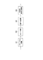
MPEG-1、MPEG-2では、例えば図11に示すような画面タイプの並びで符号化処理を行う。
【0039】
MPEGでは、画像にIピクチャ、Pピクチャ、Bピクチャという3つのタイプを規定している。
Iピクチャ(図11のn、n+6フレーム)は、フレーム内符号化(Intra符号化)を行う。Pピクチャ(図11のn+3フレーム)は、フレーム間順方向予測符号化を行う。例えば、n+3フレームはn+6の画像を参照して動き補償符号化を行う。Bピクチャ(図11のn+1,n+2,n+4,n+5フレーム)は、双方向予測符号化を行う。Bピクチャは、前後のIピクチャやPピクチャを基に、動き補償符号化を行う。
本実施例では、Pピクチャに対して透かし情報を埋め込む様にした。以下ではPピクチャの処理のみ説明する。尚、Bピクチャにも透かし情報を同様な処理で埋め込んでも当然良い。
【0040】
図10において、入力されたデジタル画像データはブロック分割回路701で水平8画素、垂直8画素で構成されるブロックに分割される。ブロック分割された画像データは、差分器702により後述する動き補償回路707から出力された画像データと差分されて、DCT回路703へ出力される。DCT回路703では、前記ブロック単位でDCT変換される。
DCT変換された画像データは、量子化回路704により量子化される。量子化された画像データは、逆量子化回路708に送られて後述する局部復号が実施されると共に、可変長符号化回路705によりハフマン符号化等の可変長符号化処理される。
【0041】
一方、逆量子化回路708では、量子化回路704から出力された画像データを逆量子化し、逆DCT回路709により符号化前の画像データに局部復号される。
この局部復号された画像データは、動き補償回路707に供給され、所定の期間保持され、そして現在の入力値である画像データと比較を行い動き検出(動きベクトル検出)を行う。動き補償回路707は、動き検出結果に従って、動き補償を行うための該当部の画像データを差分器702に供給する。
【0042】
また、動き補償回路707は、本実施例では(16×16)画素のブロック単位で動き検出を行い、前記動きベクトルデータを検出している。前記動きベクトルは、ゲート回路710と加算器711に供給される。
ゲート回路710では、透かし情報発生回路106より発生された透かし情報を、動きベクトルのレベルが所定レベル以上の時に通過するように制御する。つまり、動きベクトルが所定レベル以上の時に透かし情報がゲート回路710を通過し、加算器711によって動きベクトルデータに透かし情報が重畳される。動きベクトルが所定レベル以下の時は透かし情報はゲート回路710を通過できず、透かし情報は動きベクトルデータに重畳されない。
【0043】
加算器711から出力された動きベクトルデータは多重化回路706により符号化された画像データに多重化されて記録再生回路104へ出力される。
尚、本実施例では一つの動きベクトルの移動を透かし情報のビット列の1ビットに対応させる。動きベクトルを複数組み合わせて透かし情報とする。いくつの動きベクトルを用いるか、またどのような順序で透かし情報の1ビットを付加して行くかは、透かし情報を復元する際に必要なので、当然あらかじめその規則は決めている。
【0044】
本実施例では、動き検出から得られる動きベクトルのうち、動きの大きい部分の動きベクトルに透かし情報を埋め込むことで、画像の見えない部分に透かし情報が埋め込むことができる。画像を劣化させることがない。
また、第三者には透かしが入っている事実や場所を突き止めることが不可能となる効果があり、動画像の切り出しや改ざんをされても、デジタル透かし情報を抜き取ることができないため、動画像の不正流用の抑止効果があるばかりでなく、動画像の不正使用を突き止めることが可能になる効果がある。
【0045】
本発明は複数の機器(たとえばホストコンピュータ、インタフェース機器、リーダ、プリンタ等)から構成されるシステムに適用しても一つの機器(たとえばデジタルVTR、デジタルカメラ、デジタルテレビ)からなる装置に適用してもよい。
【0046】
また前述した実施例の機能を実現する様に各種のデバイスを動作させる様に該各種デバイスと接続された装置あるいはシステム内のコンピュータに、前記実施例の機能を実現するためのソフトウエアのプログラムコードを供給し、そのシステムあるいは装置のコンピュータ(CPUあるいはMPU)を格納されたプログラムに従って前記各種デバイスを動作させることによって実施したものも本願発明の範疇に含まれる。
【0047】
またこの場合、前記ソフトウエアのプログラムコード自体が前述した実施例の機能を実現することになり、そのプログラムコード自体、及びそのプログラムコードをコンピュータに供給するための手段、例えばかかるプログラムコードを格納した記憶媒体は本発明を構成する。
かかるプログラムコードを格納する記憶媒体としては例えばフロッピーディスク、ハードディスク、光ディスク、光磁気ディスク、CD−ROM、磁気テープ、不揮発性のメモリカード、ROM等を用いることが出来る。
【0048】
またコンピュータが供給されたプログラムコードを実行することにより、前述の実施例の機能が実現されるだけではなく、そのプログラムコードがコンピュータにおいて稼働しているOS(オペレーティングシステム)、あるいは他のアプリケーションソフト等と共同して前述の実施例の機能が実現される場合にもかかるプログラムコードは本願発明の実施形態に含まれることは言うまでもない。
【0049】
更に供給されたプログラムコードが、コンピュータの機能拡張ボードやコンピュータに接続された機能拡張ユニットに備わるメモリに格納された後そのプログラムコードの指示に基づいてその機能拡張ボードや機能格納ユニットに備わるCPU等が実際の処理の一部または全部を行い、その処理によって前述した実施例の機能が実現される場合も本願発明に含まれることは言うまでもない。
【0050】
【発明の効果】
以上の説明から明らかなように、本発明は、前後の画像を比較してデータの変化により透かし情報を抽出するようなことはできず、第三者が透かしが入っている事実や場所を突き止めることが不可能となる効果がある。これにより、画像の切り出しや改ざんをされても、デジタル透かし情報を抜き取ることができないため、画像の不正流用の抑止効果があるばかりでなく、画像の不正使用を突き止めることが可能になるという効果がある。
さらに、透かし情報の埋め込みによるデータ量の増大を抑えるとともに、画像劣化を視覚上目立たなくするという効果も有する。
【図面の簡単な説明】
【図1】本発明をビデオカメラに適用した場合の第1の実施例の構成を示すブロック図である。
【図2】本発明に係わる画像の表示例を示す図である。
【図3】第1の実施例の圧縮符号化回路103の詳細ブロック図である。
【図4】ブロックの動きを判断処理を説明するための図である。
【図5】フレーム内で動き有りのブロックを示す図である。
【図6】第2の実施例の圧縮符号化回路103の詳細ブロック図である。
【図7】本発明の第3の実施例の画像処理装置の構成を示すブロック図である。
【図8】記録媒体401に記録された符号化された画像データを生成するための符号化回路の構成を示すブロック図である。
【図9】透かし埋め込み回路403の詳細ブロック図である。
【図10】第4の実施例の圧縮符号化回路103の詳細ブロック図である。
【図11】MPEG符号化処理における画面タイプの並びの例を示す図である。
【符号の説明】
101 撮像素子
102 カメラ信号処理回路
103 圧縮符号化回路
104 記録媒体
106、406 透かし情報発生回路
201、301、701 ブロック分割回路
202、304、602、711 加算器
203、302、703 DCT回路
204、303、503、704 量子化回路
205、305、504、705 可変長符号化回路
206、306、606 動き検出回路
207、307、607 ブロック選択回路
208、308、608 フレームカウンタ
403 透かし埋め込み回路
601 可変長復号化回路
605、709 逆DCT回路
702 差分器
706 多重化回路
707 動き補償回路
708 逆量子化回路
710 ゲート回路[0001]
BACKGROUND OF THE INVENTION
The present invention relates to an image processing apparatus for embedding watermark information in image data, an image processing method, and a computer-readable recording medium storing an image processing program.
[0002]
[Prior art]
Conventional video recording / playback devices include video tape recorders that record analog video signals on magnetic tape. However, repeated copying causes image degradation, and copyright issues such as unauthorized use are not so close-up. It was.
In contrast, digital image data obtained by digitizing a video signal and sometimes compressing and encoding it is easy to handle and can be recorded not only on a digital VTR recorded on a magnetic tape but also in a computer storage device. It can be stored or transmitted via a communication line. Since this digitized image data is hardly deteriorated even if it is recorded or transmitted, there is a concern about unauthorized use.
[0003]
As a method of preventing this unauthorized use, it is known to add digital watermarks (watermarking) as ID information data such as copyright holders, senders, management numbers, distribution channels, etc. of image data to images. The digital watermark is a method in which watermark information is secretly mixed into an image so that it cannot be understood by a user who views the image, so that the source and path of an illegally diverted image can be confirmed later. In this case, it is possible to prevent deterioration of the image due to the watermark information as much as possible, to prevent only the watermark from being extracted from the image, and to prevent a significant increase in the data amount due to the watermark information being included. This becomes important.
[0004]
In the case of putting a digital watermark in a moving image, the amount of data becomes enormous if watermark information is mixed for each frame. Therefore, a method of putting only in a part of the frame has been proposed. However, if the frame interval in which the watermark is inserted is too wide, the deterrent effect when a part of the moving image is misappropriated is diminished.
[0005]
[Problems to be solved by the invention]
As described above, when a digital watermark is added to a part of a frame of a moving image, if the digital watermark is added to a part where the image does not change over several frames, there is no change in the image by comparing with the previous and next frames. Nevertheless, since the data has changed, there is a problem that not only does it become clear that the digital watermark is included, but also the position of the digital watermark becomes clear. Therefore, it becomes easy to extract only the watermark, such as extracting only the frame.
[0006]
From the background described above, one object of the present invention is to prevent the presence / absence and location of watermark information from being clarified, to suppress degradation of the image and increase in the amount of data due to insertion of watermark information, and to embed It is an object of the present invention to provide an image processing apparatus, an image processing method, and a computer-readable recording medium storing the image processing program having resistance to attacks on the watermark information.
[0007]
[Means for Solving the Problems]
An image processing apparatus according to the present invention includes an input unit that inputs image data, a motion determination unit that determines a motion of the image data, and a selection unit that selects image data that is determined to have motion in the motion determination unit. Superimposing means for superimposing watermark information on information data based on the selected image data, and the information data includes: Orthogonally transformed, It is quantized image data or motion vector data, and the superimposing means does not superimpose watermark information on image data that has not been determined to have motion by the motion determining means. .
[0008]
The image processing method of the present invention includes an input step for inputting image data, a motion determination step for determining movement of the image data, and selection for selecting image data determined to have motion in the motion determination step. A superposition step of superimposing watermark information on information data based on the selected image data, and the information data includes: Orthogonally transformed, Quantized image data or motion vector data, the superimposition Process Is characterized in that watermark information is not superimposed on image data that has not been determined to have motion in the motion determination step.
[0009]
The computer-readable storage medium of the present invention stores a computer program for causing a computer to execute each step of the image processing method of the present invention.
[0010]
DETAILED DESCRIPTION OF THE INVENTION
A first embodiment of the present invention will be described below with reference to the drawings.
FIG. 1 is a block diagram showing the configuration of a first embodiment when the present invention is applied to a video camera capable of recording and reproducing moving images.
In FIG. 1, a subject image formed on an
[0011]
The watermark
The watermark information generated by the watermark
[0012]
The encoded image data recorded on the
The watermark
[0013]
That is, the watermark
When the watermark information is supplied from the watermark
[0014]
Here, a display example of the
FIG. 2A shows an example of on-screen display of original author information among watermark information embedded with character information. In this example, since it is character information, a display character is created using a character generator in the
FIG. 2B shows an example in which the watermark information is embedded as image information instead of character information as shown in FIG. 2A. In this example, the original author information is displayed superimposed on the image.
FIG. 2C shows an example of displaying on which distribution channel this video is distributed. In this example, it is distributed on the TV.
FIG. 2D shows a display example when the watermark information is turned off.
[0015]
Next, details of the
In FIG. 3, the image data input from the camera
[0016]
The
[0017]
The block as shown in FIG. 5 determined by the
However, the
[0018]
Here, a method for superimposing watermark information on image data in the first embodiment will be described.
When embedding watermark information in image data, coded watermark information is embedded in consideration of image redundancy (noise margin).
In this embodiment, one bit of watermark information is embedded for each block having motion. By embedding over a plurality of blocks, watermark information of a plurality of bits is embedded as a whole. In addition, the watermark information must be embedded in a predetermined rule for decoding the watermark information. In this embodiment, the watermark information is sequentially embedded in a moving block from the upper left of the screen. To do. FIG. 5 shows an example of the order in which the watermark information is embedded, and the numbers given to the blocks indicate the order in which the watermark information is embedded.
[0019]
Returning to FIG. 3, the
[0020]
The image data converted by the
The watermark information may be code watermark information obtained by encoding information, or an image watermark signal expressed by luminance information or color information.
[0021]
In this embodiment, by embedding watermark information in a part of the space of the moving image, the watermark information can hardly be detected in the decoded image, but the watermark information remains in the encoded image. Has an effect.
In addition, since the watermark information is embedded only in the motion image of the moving image, the data amount is prevented from increasing, and the still image does not include the watermark information. It is not possible to extract watermark information due to changes in. Therefore, there is an effect that it becomes impossible for a third party to find out the fact or place where the watermark is included, and even if the moving image is cut out or altered, the digital watermark information cannot be extracted. Not only has the effect of deterring unauthorized use, but it also has the effect of making it possible to identify unauthorized use of moving images. Furthermore, by inserting the watermark information only in the moving part, there is an effect that the image deterioration due to the embedding of the watermark information is not visually noticeable.
[0022]
The second embodiment will be described below with reference to the drawings.
The entire configuration of the second embodiment is the same as that of the first embodiment, and has already been described with reference to FIG. However, the internal configuration of the
FIG. 6 is a detailed block diagram of the
In FIG. 6, the image data input to the
[0023]
The
The
[0024]
A block as shown in FIG. 5 determined by the
[0025]
The variable
Here, a method for superimposing watermark information on image data in the second embodiment will be described.
When embedding watermark information in image data, coded watermark information is embedded in consideration of image redundancy (noise margin).
[0026]
In this embodiment, one bit of watermark information is embedded for each block having motion. In this embodiment, watermark information is embedded in the low frequency component data of the AC component that has been DCT transformed. This is to provide resistance to various attacks such as encoding efficiency and scaling conversion of the Huffman code used in the subsequent variable-
[0027]
By embedding watermark information over a plurality of blocks as described above, a plurality of bits of watermark information are embedded as a whole. In addition, the watermark information must be embedded in a predetermined rule for decoding the watermark information. In this embodiment, the watermark information is sequentially embedded in a moving block from the upper left of the screen. To do. FIG. 5 shows an example of the order in which the watermark information is embedded, and the block numbers shown in the figure indicate the order in which the watermark information is embedded.
[0028]
Unlike the first embodiment, the present embodiment embeds watermark information in a block having motion in the spatial frequency component after DCT transform, and is more resistant to attacks than the first embodiment. In this embodiment, DCT conversion is used as a method for converting to frequency components. However, the present invention is not limited to this, and the frequency components may be converted using FFT (fast fourier transform).
[0029]
Similarly to the first embodiment, by embedding watermark information in a part of the frequency space of a moving image, the watermark information can hardly be detected in the decoded image. There is an effect that watermark information continues to remain. In addition, since the watermark information is embedded only in the motion image of the moving image, the data amount is prevented from increasing, and the still image does not include the watermark information. It is not possible to extract watermark information due to changes in. Therefore, there is an effect that it becomes impossible for a third party to find out the fact or place where the watermark is included, and even if the moving image is cut out or altered, the digital watermark information cannot be extracted. Not only has the effect of deterring unauthorized use, but it also has the effect of making it possible to identify unauthorized use of moving images. Furthermore, by inserting the watermark information only in the moving part, there is an effect that the image deterioration due to the embedding of the watermark information is not visually noticeable.
[0030]
The third embodiment will be described below with reference to the drawings.
FIG. 7 is a block diagram showing the configuration of the image processing apparatus according to the third embodiment of the present invention.
In FIG. 7, the
[0031]
The image data recorded on the
FIG. 8 is a block diagram showing a configuration of an encoding circuit for generating encoded image data recorded on the
In FIG. 8, the image data input by the blocking
[0032]
Returning to the description of FIG. 7, the watermark information generated from the watermark
[0033]
Next, details of the
FIG. 9 is a detailed block diagram of the
In FIG. 9, a variable
[0034]
The
The
[0035]
The block as shown in FIG. 5 determined by the
The image data output from the
[0036]
In the present embodiment, watermark information (copyright information, etc.) can be newly embedded in the encoded image data and distributed via the network, so that the copyright of the distributed image data is protected. Is possible.
Also, by embedding watermark information in a part of the frequency space of a moving image, the watermark information can hardly be detected in the decoded image, but the watermark information remains in the encoded image. Have.
[0037]
In addition, since the watermark information is embedded only in the motion image of the moving image, the data amount is prevented from increasing, and the still image does not include the watermark information. It is not possible to extract watermark information due to changes in. Therefore, there is an effect that it becomes impossible for a third party to find out the fact or place where the watermark is included, and even if the moving image is cut out or altered, the digital watermark information cannot be extracted. Not only has the effect of deterring unauthorized use, but it also has the effect of making it possible to identify unauthorized use of moving images. Furthermore, by inserting the watermark information only in the moving part, there is an effect that the image deterioration due to the embedding of the watermark information is not visually noticeable.
[0038]
The fourth embodiment will be described below with reference to the drawings.
The overall structure of the fourth embodiment is the same as that of the first embodiment, and has already been described with reference to FIG. However, the internal configuration of the
FIG. 10 is a detailed block diagram of the
In MPEG-1 and MPEG-2, for example, encoding processing is performed in a sequence of screen types as shown in FIG.
[0039]
MPEG defines three types of images: I picture, P picture, and B picture.
An I picture (n, n + 6 frames in FIG. 11) is subjected to intra-frame coding (Intra coding). The P picture (n + 3 frames in FIG. 11) is subjected to interframe forward prediction encoding. For example, for n + 3 frames, motion compensation coding is performed with reference to n + 6 images. B pictures (n + 1, n + 2, n + 4, n + 5 frames in FIG. 11) are subjected to bidirectional predictive coding. The B picture is subjected to motion compensation coding based on the preceding and following I pictures and P pictures.
In this embodiment, watermark information is embedded in a P picture. In the following, only P picture processing will be described. Of course, the watermark information may be embedded in the B picture by the same process.
[0040]
In FIG. 10, input digital image data is divided by a
The image data subjected to DCT conversion is quantized by the
[0041]
On the other hand, the
The locally decoded image data is supplied to the
[0042]
In the present embodiment, the
The
[0043]
The motion vector data output from the
In this embodiment, the movement of one motion vector is made to correspond to one bit of the bit string of watermark information. A plurality of motion vectors are combined to form watermark information. The number of motion vectors to be used and the order in which 1 bit of watermark information is added are necessary when restoring the watermark information, so the rules are naturally determined in advance.
[0044]
In this embodiment, by embedding watermark information in a motion vector of a portion having a large motion among motion vectors obtained from motion detection, the watermark information can be embedded in a portion where an image cannot be seen. Does not deteriorate the image.
In addition, there is an effect that makes it impossible for a third party to find out the fact and location of the watermark, and even if the moving image is cut out or altered, the digital watermark information cannot be extracted. In addition to the effect of preventing unauthorized use of the video, there is an effect that it is possible to determine the illegal use of moving images.
[0045]
The present invention can be applied to a system composed of a plurality of devices (for example, a host computer, an interface device, a reader, a printer, etc.) or an apparatus composed of one device (for example, a digital VTR, a digital camera, a digital television). Also good.
[0046]
Also, software program codes for realizing the functions of the above-described embodiments in a computer in an apparatus or a system connected to the various devices so as to operate the various devices so as to realize the functions of the above-described embodiments. Is implemented by operating the various devices according to a program stored in a computer (CPU or MPU) of the system or apparatus.
[0047]
In this case, the software program code itself realizes the functions of the above-described embodiments, and the program code itself and means for supplying the program code to the computer, for example, the program code are stored. The storage medium constitutes the present invention.
As a storage medium for storing the program code, for example, a floppy disk, a hard disk, an optical disk, a magneto-optical disk, a CD-ROM, a magnetic tape, a nonvolatile memory card, a ROM, or the like can be used.
[0048]
Further, by executing the program code supplied by the computer, not only the functions of the above-described embodiments are realized, but also the OS (operating system) in which the program code is running on the computer, or other application software, etc. It goes without saying that the program code is also included in the embodiment of the present invention even when the functions of the above-described embodiments are realized in cooperation with the embodiment.
[0049]
Further, the supplied program code is stored in the memory provided in the function expansion board of the computer or the function expansion unit connected to the computer, and then the CPU provided in the function expansion board or function storage unit based on the instruction of the program code However, it is needless to say that the present invention also includes a case where the function of the above-described embodiment is realized by performing part or all of the actual processing.
[0050]
【The invention's effect】
As is clear from the above description, the present invention cannot extract the watermark information by changing the data by comparing the previous and subsequent images, and the third party finds the fact and place where the watermark is included. There is an effect that makes it impossible. As a result, digital watermark information cannot be extracted even if the image is cut out or tampered with, so that not only is there an effect of preventing unauthorized use of the image, but it is also possible to determine the unauthorized use of the image. is there.
In addition, an increase in the amount of data due to embedding watermark information can be suppressed, and image degradation can be visually inconspicuous.
[Brief description of the drawings]
FIG. 1 is a block diagram showing a configuration of a first embodiment when the present invention is applied to a video camera.
FIG. 2 is a view showing a display example of an image according to the present invention.
FIG. 3 is a detailed block diagram of a
FIG. 4 is a diagram for explaining a block motion determination process;
FIG. 5 is a diagram showing a block with motion in a frame.
FIG. 6 is a detailed block diagram of a
FIG. 7 is a block diagram illustrating a configuration of an image processing apparatus according to a third embodiment of the present invention.
8 is a block diagram showing a configuration of an encoding circuit for generating encoded image data recorded on a
FIG. 9 is a detailed block diagram of the
FIG. 10 is a detailed block diagram of a
FIG. 11 is a diagram illustrating an example of screen type arrangement in MPEG encoding processing;
[Explanation of symbols]
101 Image sensor
102 Camera signal processing circuit
103 Compression encoding circuit
104 Recording medium
106, 406 Watermark information generation circuit
201, 301, 701 Block division circuit
202, 304, 602, 711 Adder
203, 302, 703 DCT circuit
204, 303, 503, 704 Quantization circuit
205, 305, 504, 705 Variable length coding circuit
206, 306, 606 Motion detection circuit
207, 307, 607 Block selection circuit
208, 308, 608 frame counter
403 Watermark Embedding Circuit
601 Variable length decoding circuit
605, 709 Inverse DCT circuit
702 Differencer
706 Multiplexing circuit
707 motion compensation circuit
708 Inverse quantization circuit
710 Gate circuit
Claims (9)
前記画像データの動きを判定する動き判定手段と、
前記動き判定手段において、動き有りと判定された画像データを選択する選択手段と、
前記選択された画像データに基づいた情報データに透かし情報を重畳する重畳手段とを有し、
前記情報データは、直交変換され、量子化された画像データ、または、動きベクトルデータであり、
前記重畳手段は、前記動き判定手段で、動き有りと判定されなかった画像データに対しては、透かし情報を重畳しないことを特徴とする画像処理装置。Input means for inputting image data;
Movement determining means for determining movement of the image data;
In the movement determination means, a selection means for selecting image data determined to have movement;
Superimposing means for superimposing watermark information on information data based on the selected image data,
The information data is orthogonally transformed and quantized image data or motion vector data,
The image processing apparatus according to claim 1, wherein the superimposing unit does not superimpose watermark information on image data that has not been determined to be in motion by the motion determining unit.
前記画像データの動きを判定する動き判定工程と、
前記動き判定工程において、動き有りと判定された画像データを選択する選択工程と、
前記選択された画像データに基づいた情報データに透かし情報を重畳する重畳工程とを有し、
前記情報データは、直交変換され、量子化された画像データ、または、動きベクトルデータであり、
前記重畳工程は、前記動き判定工程で、動き有りと判定されなかった画像データに対しては、透かし情報を重畳しないことを特徴とする画像処理方法。An input process for inputting image data;
A motion determination step of determining the motion of the image data;
A selection step of selecting image data determined to have movement in the movement determination step;
A superimposition step of superimposing watermark information on information data based on the selected image data,
The information data is orthogonally transformed and quantized image data or motion vector data,
The image processing method, wherein the superimposing step does not superimpose watermark information on image data that has not been determined to have motion in the motion determination step.
Priority Applications (2)
| Application Number | Priority Date | Filing Date | Title |
|---|---|---|---|
| JP09759099A JP4035257B2 (en) | 1998-04-10 | 1999-04-05 | Image processing apparatus, image processing method, and computer-readable storage medium |
| US09/288,219 US6639996B2 (en) | 1998-04-10 | 1999-04-08 | Image processing apparatus, image processing method and computer readable memory medium |
Applications Claiming Priority (3)
| Application Number | Priority Date | Filing Date | Title |
|---|---|---|---|
| JP9894998 | 1998-04-10 | ||
| JP10-98949 | 1998-04-10 | ||
| JP09759099A JP4035257B2 (en) | 1998-04-10 | 1999-04-05 | Image processing apparatus, image processing method, and computer-readable storage medium |
Publications (2)
| Publication Number | Publication Date |
|---|---|
| JPH11355736A JPH11355736A (en) | 1999-12-24 |
| JP4035257B2 true JP4035257B2 (en) | 2008-01-16 |
Family
ID=26438756
Family Applications (1)
| Application Number | Title | Priority Date | Filing Date |
|---|---|---|---|
| JP09759099A Expired - Fee Related JP4035257B2 (en) | 1998-04-10 | 1999-04-05 | Image processing apparatus, image processing method, and computer-readable storage medium |
Country Status (2)
| Country | Link |
|---|---|
| US (1) | US6639996B2 (en) |
| JP (1) | JP4035257B2 (en) |
Families Citing this family (24)
| Publication number | Priority date | Publication date | Assignee | Title |
|---|---|---|---|---|
| US8332478B2 (en) * | 1998-10-01 | 2012-12-11 | Digimarc Corporation | Context sensitive connected content |
| US20020032734A1 (en) | 2000-07-26 | 2002-03-14 | Rhoads Geoffrey B. | Collateral data combined with user characteristics to select web site |
| JP2001111808A (en) * | 1999-10-05 | 2001-04-20 | Nec Corp | Electronic watermark data inserting system and device |
| EP1172007A1 (en) * | 2000-01-14 | 2002-01-16 | Koninklijke Philips Electronics N.V. | Transcoding method and device |
| JP3549097B2 (en) * | 2000-04-26 | 2004-08-04 | インターナショナル・ビジネス・マシーンズ・コーポレーション | Method for identifying owner of collaborative work object, computer system, and computer-readable recording medium |
| JP2002084510A (en) * | 2000-09-08 | 2002-03-22 | Jisedai Joho Hoso System Kenkyusho:Kk | Method and apparatus for embedding electronic watermark |
| US7095870B2 (en) * | 2000-12-21 | 2006-08-22 | Hitachi, Ltd. | Electronic watermark embedding apparatus and method and a format conversion device having a watermark embedding function |
| KR100383836B1 (en) * | 2001-05-30 | 2003-05-14 | 한국과학기술원 | Watermarking insert and analysis method of robust motion based on multi-resolution analysis |
| JP3861624B2 (en) | 2001-06-05 | 2006-12-20 | ソニー株式会社 | Digital watermark embedding processing apparatus, digital watermark embedding processing method, and program |
| JP3861623B2 (en) | 2001-06-05 | 2006-12-20 | ソニー株式会社 | Digital watermark embedding processing apparatus, digital watermark embedding processing method, and program |
| US7020304B2 (en) | 2002-01-22 | 2006-03-28 | Digimarc Corporation | Digital watermarking and fingerprinting including synchronization, layering, version control, and compressed embedding |
| US7424128B2 (en) | 2002-04-10 | 2008-09-09 | Pioneer Corporation | Electronic watermark embedding apparatus, electronic watermark embedding method, record medium having electronic watermark and manufacturing method of record medium |
| JP2004048219A (en) * | 2002-07-10 | 2004-02-12 | Hitachi Ltd | Inserting method of electronic watermark information |
| EP1398732A3 (en) * | 2002-09-04 | 2006-09-27 | Matsushita Electric Industrial Co., Ltd. | Digital watermark-embedding and detecting |
| JP2006505171A (en) * | 2002-10-30 | 2006-02-09 | コーニンクレッカ フィリップス エレクトロニクス エヌ ヴィ | Adaptive watermark |
| FR2846828B1 (en) * | 2002-10-31 | 2005-03-11 | France Telecom | METHOD FOR TATOTING A VIDEO SIGNAL, SYSTEM AND DATA CARRIER FOR IMPLEMENTING SAID METHOD, METHOD FOR EXTRACTING THE TATTOO OF A VIDEO SIGNAL, SYSTEM FOR IMPLEMENTING SAID METHOD |
| US20040208231A1 (en) * | 2003-04-17 | 2004-10-21 | G-Mix Co., Ltd. | Concealing process of digital information |
| BRPI0409745A (en) * | 2003-04-25 | 2006-05-09 | Thomson Licensing | tagging techniques for tracking pirated media content |
| WO2005011300A2 (en) * | 2003-07-15 | 2005-02-03 | Transchip, Inc. | Data overlay for a digital camera module |
| CN1965584A (en) * | 2004-06-08 | 2007-05-16 | 皇家飞利浦电子股份有限公司 | Compensating watermark irregularities caused by moved objects |
| JP4321550B2 (en) | 2005-08-31 | 2009-08-26 | ソニー株式会社 | Information processing apparatus, information recording medium manufacturing apparatus, information recording medium and method, and computer program |
| JP5859845B2 (en) * | 2011-12-27 | 2016-02-16 | Jfeスチール株式会社 | Threading plate abnormality detection device |
| US20130188712A1 (en) * | 2012-01-24 | 2013-07-25 | Futurewei Technologies, Inc. | Compressed Domain Watermarking with Reduced Error Propagation |
| CA2993346C (en) | 2015-07-24 | 2023-08-15 | Info Wise Limited | Wireless access tag duplication system and method |
Family Cites Families (12)
| Publication number | Priority date | Publication date | Assignee | Title |
|---|---|---|---|---|
| US5646997A (en) * | 1994-12-14 | 1997-07-08 | Barton; James M. | Method and apparatus for embedding authentication information within digital data |
| US6226387B1 (en) * | 1996-08-30 | 2001-05-01 | Regents Of The University Of Minnesota | Method and apparatus for scene-based video watermarking |
| US6282299B1 (en) * | 1996-08-30 | 2001-08-28 | Regents Of The University Of Minnesota | Method and apparatus for video watermarking using perceptual masks |
| US6052780A (en) * | 1996-09-12 | 2000-04-18 | Open Security Solutions, Llc | Computer system and process for accessing an encrypted and self-decrypting digital information product while restricting access to decrypted digital information |
| US5809139A (en) * | 1996-09-13 | 1998-09-15 | Vivo Software, Inc. | Watermarking method and apparatus for compressed digital video |
| JP3686741B2 (en) * | 1997-02-19 | 2005-08-24 | 富士通株式会社 | Identification information embedding method in image data, identification information extraction method from image data in which identification information is embedded, identification information embedding device in image data, identification information extraction device from image data in which identification information is embedded, and computer Readable medium |
| US5960081A (en) * | 1997-06-05 | 1999-09-28 | Cray Research, Inc. | Embedding a digital signature in a video sequence |
| US6208735B1 (en) * | 1997-09-10 | 2001-03-27 | Nec Research Institute, Inc. | Secure spread spectrum watermarking for multimedia data |
| US6101602A (en) * | 1997-12-08 | 2000-08-08 | The United States Of America As Represented By The Secretary Of The Air Force | Digital watermarking by adding random, smooth patterns |
| US6037984A (en) * | 1997-12-24 | 2000-03-14 | Sarnoff Corporation | Method and apparatus for embedding a watermark into a digital image or image sequence |
| US6208745B1 (en) * | 1997-12-30 | 2001-03-27 | Sarnoff Corporation | Method and apparatus for imbedding a watermark into a bitstream representation of a digital image sequence |
| US6188728B1 (en) * | 1998-09-29 | 2001-02-13 | Sarnoff Corporation | Block motion video coding and decoding |
-
1999
- 1999-04-05 JP JP09759099A patent/JP4035257B2/en not_active Expired - Fee Related
- 1999-04-08 US US09/288,219 patent/US6639996B2/en not_active Expired - Lifetime
Also Published As
| Publication number | Publication date |
|---|---|
| US20020114488A1 (en) | 2002-08-22 |
| US6639996B2 (en) | 2003-10-28 |
| JPH11355736A (en) | 1999-12-24 |
Similar Documents
| Publication | Publication Date | Title |
|---|---|---|
| JP4035257B2 (en) | Image processing apparatus, image processing method, and computer-readable storage medium | |
| KR100553469B1 (en) | Electronic watermark data insertion apparatus and electronic watermark data detection apparatus | |
| Langelaar et al. | Real-time labeling of MPEG-2 compressed video | |
| JP3768705B2 (en) | Digital watermark embedding device, output control device, and computer-readable storage medium | |
| US6810131B2 (en) | Information processing method and apparatus | |
| US6798893B1 (en) | Digital watermarking technique | |
| JP3137022B2 (en) | Video encoding device | |
| JP4617049B2 (en) | Method and apparatus for embedding data in an encoded digital bitstream | |
| EP0860997A2 (en) | Digital data encode system | |
| US6449378B1 (en) | Data processing apparatus and method and storage medium | |
| EP1164543A2 (en) | Digital information embedding/extracting | |
| US7526099B2 (en) | Motion picture data processing device, method, and program | |
| JP4023324B2 (en) | Watermark embedding and image compression unit | |
| KR100643273B1 (en) | Video watermarking method and apparatus, video content protecting method and apparatus using video watermarking | |
| JP2001111808A (en) | Electronic watermark data inserting system and device | |
| JP3353691B2 (en) | Digital data encoding system, digital watermark data insertion method, and storage medium storing control program | |
| JP3480700B2 (en) | Digital watermark recording method and digital watermark recording device | |
| Chaumont | Ensuring security of H. 264 videos by using watermarking | |
| JP2000083254A (en) | Moving picture coding method and moving picture decoding method | |
| JP4588514B2 (en) | Scrambled video distribution system and playback device | |
| JP3933140B2 (en) | Electronic watermark data insertion method and apparatus | |
| JP4020302B2 (en) | Information embedding device and information extracting device | |
| CA2230183C (en) | Digital data encode system | |
| JP2006270988A (en) | Method for inserting electronic watermark data, its device and electronic watermark data detector | |
| Busch et al. | Video Watermarking: Requirements |
Legal Events
| Date | Code | Title | Description |
|---|---|---|---|
| A131 | Notification of reasons for refusal |
Free format text: JAPANESE INTERMEDIATE CODE: A131 Effective date: 20061212 |
|
| A521 | Request for written amendment filed |
Free format text: JAPANESE INTERMEDIATE CODE: A523 Effective date: 20070201 |
|
| A131 | Notification of reasons for refusal |
Free format text: JAPANESE INTERMEDIATE CODE: A131 Effective date: 20070731 |
|
| A521 | Request for written amendment filed |
Free format text: JAPANESE INTERMEDIATE CODE: A523 Effective date: 20070829 |
|
| TRDD | Decision of grant or rejection written | ||
| A01 | Written decision to grant a patent or to grant a registration (utility model) |
Free format text: JAPANESE INTERMEDIATE CODE: A01 Effective date: 20071009 |
|
| A61 | First payment of annual fees (during grant procedure) |
Free format text: JAPANESE INTERMEDIATE CODE: A61 Effective date: 20071029 |
|
| FPAY | Renewal fee payment (event date is renewal date of database) |
Free format text: PAYMENT UNTIL: 20101102 Year of fee payment: 3 |
|
| R150 | Certificate of patent or registration of utility model |
Free format text: JAPANESE INTERMEDIATE CODE: R150 |
|
| FPAY | Renewal fee payment (event date is renewal date of database) |
Free format text: PAYMENT UNTIL: 20101102 Year of fee payment: 3 |
|
| FPAY | Renewal fee payment (event date is renewal date of database) |
Free format text: PAYMENT UNTIL: 20111102 Year of fee payment: 4 |
|
| FPAY | Renewal fee payment (event date is renewal date of database) |
Free format text: PAYMENT UNTIL: 20121102 Year of fee payment: 5 |
|
| FPAY | Renewal fee payment (event date is renewal date of database) |
Free format text: PAYMENT UNTIL: 20131102 Year of fee payment: 6 |
|
| LAPS | Cancellation because of no payment of annual fees |