JP4031442B2 - Image processing apparatus and image forming apparatus having the same - Google Patents
Image processing apparatus and image forming apparatus having the same Download PDFInfo
- Publication number
- JP4031442B2 JP4031442B2 JP2004002197A JP2004002197A JP4031442B2 JP 4031442 B2 JP4031442 B2 JP 4031442B2 JP 2004002197 A JP2004002197 A JP 2004002197A JP 2004002197 A JP2004002197 A JP 2004002197A JP 4031442 B2 JP4031442 B2 JP 4031442B2
- Authority
- JP
- Japan
- Prior art keywords
- image data
- data
- image
- histogram
- processing unit
- Prior art date
- Legal status (The legal status is an assumption and is not a legal conclusion. Google has not performed a legal analysis and makes no representation as to the accuracy of the status listed.)
- Expired - Fee Related
Links
Images


Landscapes
- Record Information Processing For Printing (AREA)
- Image Processing (AREA)
- Compression Of Band Width Or Redundancy In Fax (AREA)
Description
本発明は、本発明は、画像データの圧縮処理及び伸張処理を行う画像処理装置、及びそれを備える画像形成装置に関する。 The present invention relates to an image processing apparatus that performs compression processing and decompression processing of image data, and an image forming apparatus including the image processing apparatus.
周知の様に、複写機、プリンタ、ファクシミリ装置等のデジタル画像形成装置においては、画像データを入力すると、画像データに対して各種の画像処理を施してから、画像データを電子写真方式やインクジェット方式等の出力エンジンに出力して、画像データによって示される画像の記録を行っている。 As is well known, in digital image forming apparatuses such as copiers, printers, and facsimile machines, when image data is input, the image data is subjected to various image processing and then the image data is electrophotographic or inkjet. The image indicated by the image data is recorded on the output engine.
各種の画像処理を行う画像処理部としては、高速処理のために、ASIC(Application Specific Integrated Circuit:特定用途向け集積回路)やDSP(Digital Signal Processor:デジタル信号処理プロセッサ)を用いることが多い。また、画像処理の内容によっては、大容量のメモリを必要とし、画像データをASICやDSP内のメモリ又は外部のより大容量のメモリ等に一旦書き出し、必要になった時点で、画像データをメモリから読み込むという処理を行う。 As an image processing unit that performs various types of image processing, an ASIC (Application Specific Integrated Circuit) or a DSP (Digital Signal Processor) is often used for high-speed processing. Depending on the contents of the image processing, a large capacity memory is required, and the image data is once written in the memory in the ASIC or DSP, or in a larger external memory, etc., and the image data is stored in the memory when necessary. Read from.
この様なメモリへの書き出し及び読み込みに際しては、通常、圧縮処理を行わない。これは、画像処理における各ステップで画像データをメモリに対して入出力するに度に、画像データを圧縮伸張し、かつ多様な画像データの全てについて平均的に高圧縮率を達成するならば、圧縮伸張アルゴリズムが複雑になり、またメモリ帯域に見合うだけのスループットを持つ圧縮伸張処理回路を設ける必要あり、回路規模が膨大となるためである。 When writing to and reading from such a memory, compression processing is usually not performed. This means that each time image data is input / output to / from the memory at each step in image processing, the image data is compressed and expanded, and an average high compression ratio is achieved for all of the various image data. This is because the compression / decompression algorithm becomes complicated, and it is necessary to provide a compression / decompression processing circuit having a throughput corresponding to the memory bandwidth, and the circuit scale becomes enormous.
一方、特許文献1には、プレスキャンにより得られた画像の各画素の濃度に関するヒストグラムを形成し、このヒストグラムに基づいて、予め定められた複数の圧縮処理方式のいずれかを選択し、この選択した圧縮処理方式を用いて、本スキャンにより得られた画像を圧縮するという技術が開示されている。
画像処理速度は、画像データを一時的に記憶するメモリと密接な関係にある。所望の画像処理速度を達成するには、画像処理に際して画像データをメモリに対して入出力するのに必要な一定のメモリ帯域が要求される。この要求されるメモリ帯域が実際のメモリのメモリ帯域以内でなければ、その画像処理速度が保障されない。 The image processing speed is closely related to a memory that temporarily stores image data. In order to achieve a desired image processing speed, a certain memory bandwidth required for inputting / outputting image data to / from the memory during image processing is required. If the required memory bandwidth is not within the memory bandwidth of the actual memory, the image processing speed cannot be guaranteed.
メモリへの書き出し及び読み込みに際し、画像データの圧縮伸張を行わなければ、画像データが大きく、メモリ帯域を当然増やす必要があり、メモリ容量も大きくなければならない。 If the image data is not compressed and expanded when writing to and reading from the memory, the image data is large, the memory bandwidth must be increased, and the memory capacity must be large.
これに対して画像データの圧縮伸張を行うならば、書き出し及び読み込みされる画像データが元の画像データよりも小さくなり、メモリ帯域を減らすことができ(見かけ上のメモリ帯域が実際のメモリ帯域よりも増える)、メモリ容量も小さくすることができる。しかしながら、先に述べた様にメモリ帯域に見合うだけのスループットを持つ圧縮伸張回路を設けると、回路規模が大きくなる。このため、簡単な圧縮伸張アルゴリズムの採用が考えられるが、この場合には、多様な画像データの全てについて平均的に高圧縮率を得ることができない。 On the other hand, if the image data is compressed / decompressed, the image data to be written and read becomes smaller than the original image data, and the memory bandwidth can be reduced (the apparent memory bandwidth is larger than the actual memory bandwidth). Memory capacity can be reduced. However, if a compression / decompression circuit having a throughput corresponding to the memory bandwidth is provided as described above, the circuit scale increases. For this reason, a simple compression / decompression algorithm may be employed. In this case, however, a high compression rate cannot be obtained on average for all of various image data.
更に、特許文献1では、プレスキャンにより得られた画像の各画素の濃度に関するヒストグラムに基づいて、複数の圧縮処理方式のいずれかを選択しているものの、多様な画像データの全てについて平均的に高圧縮率を得るには、多くの圧縮処理方式を準備する必要があり、やはり回路規模が増大する。
Furthermore, in
そこで、本発明は、上記問題点に鑑みなされたものであり、回路規模を抑えつつ、多様な画像データについて平均的に高圧縮率を達成することができ、必要メモリ帯域及び必要メモリ容量の削減を実現することが可能な画像処理装置及びそれを備える画像形成装置を提供することを目的とする。 Therefore, the present invention has been made in view of the above problems, and can achieve a high compression ratio on average for various image data while reducing the circuit scale, and reducing the required memory bandwidth and the required memory capacity. An object of the present invention is to provide an image processing apparatus capable of realizing the above and an image forming apparatus including the same.
上記課題を解決するために、本発明は、同一画像を示す第1及び第2画像データを取得し、第1画像データを用いて、第2画像データの圧縮伸張を行う画像処理装置において、第1画像データのヒストグラムデータを作成するヒストグラム作成手段と、ヒストグラム作成手段により作成されたヒストグラムデータに対して補正処理を行って、補正ヒストグラムデータを作成するヒストグラム補正手段と、ヒストグラム補正手段により作成された補正ヒストグラムデータに応じた圧縮伸張率で、第2画像データの可逆的な圧縮伸張を行う圧縮伸張手段と、圧縮された第2画像データの書き込み読み出しを行う記憶手段とを備えている。 In order to solve the above-described problem, the present invention provides an image processing apparatus that acquires first and second image data indicating the same image and compresses and expands the second image data using the first image data. Histogram creation means for creating histogram data of one image data, histogram correction means for creating correction histogram data by performing correction processing on the histogram data created by the histogram creation means, and histogram correction means A compression / expansion unit that performs reversible compression / expansion of the second image data at a compression / expansion rate according to the correction histogram data , and a storage unit that writes and reads the compressed second image data are provided.
また、本発明においては、ヒストグラムデータに対して補正処理を行って、補正ヒストグラムデータを作成し、補正ヒストグラムデータに基づいて、第2画像データを圧縮伸張している。 In the present invention, correction processing is performed on the histogram data to generate correction histogram data, and the second image data is compressed and expanded based on the correction histogram data.
更に、本発明においては、画像を複数ブロックに分割し、ブロック毎に、ヒストグラムデータを作成し、第2画像データを圧縮伸張している。 Furthermore, in the present invention, the image is divided into a plurality of blocks, histogram data is created for each block, and the second image data is compressed and expanded.
また、本発明においては、圧縮された第2画像データのデータサイズが一定サイズ以上の場合は、非圧縮状態の第2画像データの書き込み読み出しを記憶手段に対して行っている。 In the present invention, when the data size of the compressed second image data is equal to or larger than a certain size, the storage unit performs writing / reading of the uncompressed second image data.
一方、本発明の画像形成装置は、上記本発明の画像処理装置を備えている。 On the other hand, an image forming apparatus of the present invention includes the image processing apparatus of the present invention.
本発明によれば、同一画像を示す第1及び第2画像データを取得し、第1画像データのヒストグラムデータを作成して、ヒストグラムデータに応じた圧縮伸張率で、第2画像データの圧縮伸張を行っている。従って、多様な画像であっても、ヒストグラムデータ(画像の濃度ヒストグラム)を把握し、ヒストグラムデータに基づいて、第2画像データを効率的に圧縮することができ、記憶手段の記憶容量の低減とメモリ帯域の見かけ上の増大が可能となる。 According to the present invention, first and second image data representing the same image is acquired, histogram data of the first image data is created, and the second image data is compressed and decompressed at a compression / decompression ratio according to the histogram data. It is carried out. Therefore, even for various images, the histogram data (image density histogram) can be grasped, and the second image data can be efficiently compressed based on the histogram data, and the storage capacity of the storage means can be reduced. An apparent increase in memory bandwidth is possible.
また、ヒストグラムデータに対して補正処理を行い、補正ヒストグラムデータに基づいて、第2画像データを圧縮伸張するので、ノイズ等を原因として第1及び第2画像データ間で濃度ヒストグラムの変化が発生しても、データの圧縮率の低下を抑えることができる。 In addition, since the correction processing is performed on the histogram data and the second image data is compressed and expanded based on the correction histogram data, a change in the density histogram occurs between the first and second image data due to noise or the like. However, it is possible to suppress a decrease in the data compression rate.
更に、画像を複数ブロックに分割し、ブロック毎に、ヒストグラムデータを作成し、第2画像データを圧縮伸張しているので、画像中の局所的な濃度変化をヒストグラムデータに反映させて、第2画像データの圧縮伸張を行うことができ、データの圧縮率の低下を抑えることができる。 Furthermore, since the image is divided into a plurality of blocks, histogram data is created for each block, and the second image data is compressed and expanded, the local density change in the image is reflected in the histogram data, and the second Image data can be compressed and expanded, and a reduction in data compression rate can be suppressed.
また、圧縮された第2画像データのデータサイズが一定サイズ以上の場合は、非圧縮状態の第2画像データの書き込み読み出しを記憶手段に対して行っているので、記憶手段の記憶容量を無駄に用いることがない。 In addition, when the data size of the compressed second image data is equal to or larger than a certain size, the storage means is used to write and read the uncompressed second image data, so the storage capacity of the storage means is wasted. Not used.
尚、本発明の画像形成装置は、上記本発明の画像処理装置と同様の作用及び効果を果たすことができる。 The image forming apparatus of the present invention can achieve the same operations and effects as the image processing apparatus of the present invention.
以下、本発明の実施例を添付図面を参照しつつ詳細に説明する。 Hereinafter, embodiments of the present invention will be described in detail with reference to the accompanying drawings.
図1は、本発明の画像形成装置の実施例1を示すブロック図である。本実施例の画像形成装置10は、デジタル複写機であり、スキャナ部(画像入力装置)11、画像処理部(画像処理装置)12、エンジン部(画像出力装置)13、コンソール14、コントローラ15、及びメモリ16を備えている。
FIG. 1 is a block
スキャナ部11は、図示しないCCD(Charge Coupled Device)ラインイメージセンサユニット、及びCCDラインイメージセンサユニットを副走査方向に往復移動させる副走査方向駆動系を備えている。CCDラインイメージセンサユニットは、原稿画像を副走査方向に走査しつつ該原稿画像を主走査方向に繰り返し走査し、1主走査ライン毎に、RGB(R:赤・G:緑・B:青)カラー信号を生成出力する。CCDラインイメージセンサユニットの出力のうちの有効範囲(原稿の読み取り範囲)に対応するカラー信号のみが選択され、このカラー信号がA/D変換されて、RGB画像データが生成され画像処理部12に出力される。
The
画像処理部12は、ASICで構成されており、スキャナ部11からのRGB画像データを受け取り、RGB画像データに対して各種の画像処理を施してから、RGB画像データをCMYK(C:青緑・M:深紅・Y:黄・K:黒)画像データに変換し、このCMYK画像データをエンジン部13へ出力する。
The
コントローラ15は、汎用CPU(Central Processing Unit )で構成され、スキャナ部11、画像処理部12、及びエンジン部13を制御し、一連の複写動作の制御を実施する。コンソール14は、図示しないが、ユーザとのインタフェースを行うための液晶表示装置、動作指示用のボタン類等から構成されている。
The
エンジン部13は、図示しないCMYKの4色トナーを用いたタンデム型の電子写真方式のカラー出力エンジンであり、画像処理部12から1ページ分のCMYK画像データを受け取り、CMYK画像データにより示されるカラーの原稿画像を記録用紙に記録する。
The
メモリ16は、例えばDRAM(Dynamic Random Access Memory)やSRAM(Static Random Access Memory)で構成される大容量のデータを格納するための記憶装置であり、画像処理部12からの画像データを一時的に記憶する。
The
次に、本実施形態の画像形成装置10における画像処理部12を更に詳しく説明する。
Next, the
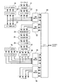
図2は、画像処理部12の構成を示すブロック図である。この画像処理部12は、メモリインタフェース20、シェーディング補正処理部21、入力ガンマ処理部22、カラー画像判定部23、解像度変換処理部24、領域分離処理部25、フィルタ処理部26、色補正処理部27、中間調処理部28、ヒストグラム算出部A29、ヒストグラム補正部A30、圧縮処理部A31、伸張処理部A32、ヒストグラム算出部B33、ヒストグラム補正部B34、圧縮処理部B35、伸張処理部B36を備えている。
FIG. 2 is a block diagram illustrating a configuration of the
メモリインタフェース20は、圧縮処理部A31、伸張処理部A32、圧縮処理部B35、及び伸張処理部B36とメモリ16間の画像データの入出力制御を行うインタフェースである。
The
シェーディング補正処理部21は、CCDラインイメージセンサユニット(主走査方向)の受光量分布が均一でない状態でのRGB画像データを補正して、このRGB画像データを受光量分布が均一な状態でのRGB画像データに変換する。すなわち、スキャナ部11からのRGB画像データに対して、読み取り原稿の照明系、結像系、撮像系で生じる各種の歪みを取り除く処理を行う。
The shading
入力ガンマ処理部22は、スキャナ部11からのRGB画像データがCCDラインイメージセンサユニットの感度にリニアになる様に、スキャナ部11の入力特性を補正して、RGB画像データを後段の画像処理で扱い易くする。
The input
カラー画像判別部23は、入力ガンマ処理部22からのRGB画像データによって示される原稿画像がカラー及びモノクロのいずれであるかを判別する。
The color
ヒストグラム算出部A29は、入力ガンマ処理部22からのRGB画像データによって示される画像を構成する各画素の色と階調を参照し、各色の256階調についての度数データ(ヒストグラムデータ)を作成する。このため、ヒストグラム算出部A29は、RGBの各色別に、256階調の出現度数をそれぞれカウントする256個の度数カウンタ、合計768個の度数カウンタを内蔵する。
The histogram calculation unit A29 refers to the color and gradation of each pixel constituting the image indicated by the RGB image data from the input
ヒストグラム補正部A30は、ヒストグラム算出部A29により算出されたヒストグラムデータの変動を考慮し、出現度数分布を補正した補正ヒストグラムデータを算出し、補正ヒストグラムデータに基づいて静的なハフマン符号化テーブルを作成する。 The histogram correction unit A30 calculates corrected histogram data in which the appearance frequency distribution is corrected in consideration of fluctuations in the histogram data calculated by the histogram calculation unit A29, and creates a static Huffman coding table based on the corrected histogram data To do.
圧縮処理部A31は、ヒストグラム補正部A30により作成されたハフマン符号化テーブルを用いて、入力ガンマ処理部22からのRGB画像データをハフマン符号化して、これにより圧縮されたRGB画像データをメモリインタフェース20を通じてメモリ16に記憶する。
The compression processing unit A31 performs Huffman coding on the RGB image data from the input
伸張処理部A32は、圧縮処理部A31により圧縮されたRGB画像データをメモリインタフェース20を通じてメモリ16から読み出し、ハフマン符号化テーブルを用いて、このRGB画像データを復号化して伸長し、元の非圧縮状態のRGB画像データを得る。
The decompression processing unit A32 reads out the RGB image data compressed by the compression processing unit A31 from the
解像度変換処理部24は、伸張処理部A32からのRGB画像データを用いて、主走査方向もしくは副走査方向に変倍した原稿画像を示すRGB画像データを生成して出力する。解像度変換により拡大を行う場合には、画像データのデータ量が増えるため、画像データをメモリに一旦保存してから、画像データをメモリから再度読み出すことにより、処理速度を一定に保つ必要がある。
The resolution
領域分離処理部25は、RGB画像データによって示される画像の各画素に対して、文字を表す画素かそれ以外を表す画素かを示す属性フラッグの1ビットを付加する。
The area
フィルタ処理部26は、画素毎に、RGB画像データを2次元FIR(Finite Impulse Response )フィルタにかけるものであって、画素の属性フラッグを用い、画素が文字を表せば、RGB画像データを強調フィルタ処理にかけて、文字エッジを強調し、画素がそれ以外を表せば、RGB画像データを平滑フィルタにかけて、ノイズの除去を行う。
The
色補正処理部27は、RGB画像データをCMYK画像データに変換する。すなわち、色再現の忠実化実現のために、不要吸収成分を含むCMYK色材の分光特性をテーブルで参照して、RGB値をCMYK値に直接変換する。このCMYK画像データは、CMYKの各色別に256階調を表す。
The color
中間調処理部28は、CMYKの各色別に256階調を表すCMYK画像データを色補正処理部26から受け取ると、多値ディザ処理を行って、CMYKの各色別の256階調をエンジン部13の階調表現能力に合わせたCMYKの各色別の16階調で表現したCMYK画像データを生成出力する。
When the
ヒストグラム算出部B33は、中間調処理部28からのCMYK画像データを受け取り、CMYK画像データによって示される画像を構成する各画素の色と階調を参照し、各色の16階調についての度数データ(ヒストグラムデータ)を作成する。このため、ヒストグラム算出部B33は、CMYKの各色別に、16階調の出現度数をそれぞれカウントする16個の度数カウンタ、合計64個の度数カウンタを内蔵する。
The histogram calculation unit B33 receives the CMYK image data from the
ヒストグラム補正部B34は、ヒストグラム算出部B33が算出したヒストグラムデータの変動を考慮し、出現度数分布を補正した補正ヒストグラムデータを算出し、補正ヒストグラムデータに基づいて静的なハフマン符号化テーブルを作成する。 The histogram correction unit B34 calculates corrected histogram data in which the appearance frequency distribution is corrected in consideration of fluctuations in the histogram data calculated by the histogram calculation unit B33, and creates a static Huffman coding table based on the corrected histogram data. .
圧縮処理部B35は、ヒストグラム補正部B34により作成されたハフマン符号化テーブルを用いて、中間調処理部28からのCMYK画像データをハフマン符号化して、これにより圧縮されたCMYK画像データをメモリインタフェース20を通じてメモリ16に記憶する。
The compression processing unit B35 performs Huffman coding on the CMYK image data from the
伸張処理部B36は、圧縮処理部B35により圧縮されたCMYK画像データをメモリインタフェース20を通じてメモリ16から読み出し、ハフマン符号化テーブルを用いて、このCMYK画像データを復号化して伸長し、元の未圧縮状態のCMYK画像データを得る。
The decompression processing unit B36 reads the CMYK image data compressed by the compression processing unit B35 from the
伸張処理部B36からのCMYK画像データは、エンジン部13による原稿画像の記録タイミングに合わせて、CMYKの各色別にエンジン部13へと出力される。
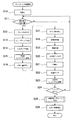
次に、図3のフローチャートを参照して、画像処理部12を中心とする処理の概略を説明する。
The CMYK image data from the expansion processing unit B36 is output to the
Next, an outline of processing centered on the
ここでは、ステップS1のプレスキャン処理を行ってから、ステップS2の本スキャン処理を行っている。 Here, after performing the pre-scan process of step S1, the main scan process of step S2 is performed.
ステップS1のプレスキャン処理においては、スキャナ部11による原稿画像の読み取り走査、及び画像処理部12による処理が行なわれて、原稿画像がカラー及びモノクロのいずれであるかが判別され、RGB画像データを圧縮伸張するのに必用なハフマン符号化テーブルが作成され、CMYK画像データを圧縮伸張するのに必用なハフマン符号化テーブルも作成される。ただし、CMYK画像データをエンジン部13に出力することはない。
In the pre-scan process in step S1, a document image is read and scanned by the
ステップS2の本スキャン処理においては、スキャナ部11による原稿画像の読み取り走査、及び画像処理部12による処理が行なわれて、プレスキャン処理により作成されたハフマン符号化テーブルを用いて、RGB画像データの圧縮伸張、メモリ16に対する圧縮されたRGB画像データの読み書き、CMYK画像データの圧縮伸張、メモリ16に対する圧縮されたCMYK画像データの読み書きが行われる。そして、CMYK画像データをエンジン部13に出力する。
In the main scan process of step S2, the original image is scanned by the
次に、図4のフローチャートを参照して、ステップS1のプレスキャン処理を説明する。 Next, the prescan process in step S1 will be described with reference to the flowchart of FIG.
まず、ステップS10において、画像処理部12の初期化が行われ、画像処理部12の各種動作パラメータがコントローラ15により設定される。このとき、ヒストグラム算出部A29及びヒストグラム算出部B33内の度数カウンタも初期化される。
First, in step S <b> 10, the
ステップS11において、スキャナ部11のCCDラインイメージセンサユニットが副走査方向に移動されて、読み取り位置に来たか否かが判定される。読み取り位置は、スキャナ部11の入力解像度を600dpi(dot per inch)とすると、1インチの区間を600分割したそれぞれの位置である。
In step S11, it is determined whether the CCD line image sensor unit of the
ステップS12において、スキャナ部11は、読み取り位置に移動されると、RGBの各色別に、主走査1ライン分の各画素値を読み取って、各画素の値を10ビットのデジタル信号にそれぞれ変換し、このデジタル信号をRGB画像データとして画像処理部12に出力する。
In step S12, when moved to the reading position, the
ステップS13において、シェーディング補正処理部21は、主走査1ライン分のRGB画像データを受け取ると、RGB画像データにシェーディング補正処理を施す。これに伴って、各画素の値を示す10ビットのデジタル信号が8ビットのデジタル信号に変換される。
In step S13, when the shading
ステップS14において、入力ガンマ補正処理部22は、スキャナ部11の入力特性を補正して、RGB画像データを後段の画像処理で扱い易くする。
In step S14, the input gamma
ステップS15において、ヒストグラム算出部A29は、入力ガンマ処理部22からの主走査1ライン分のRGB画像データによって示される主走査1ライン分の各画素の色と階調を参照し、各色別の256階調の出現度数に応じて該ヒストグラム算出部A29内の256個の度数カウンタをそれぞれインクリメントして、各色別に、256階調の出現度数を計数する。
In step S15, the histogram calculation unit A29 refers to the color and gradation of each pixel for one main scanning line indicated by the RGB image data for one main scanning line from the input
ステップS16において、入力ガンマ補正処理部22からの主走査1ライン分のRGB画像データをメモリ16に一旦書き込む。このとき、圧縮処理部A31は、ハフマン符号化処理を実施せず、主走査1ライン分のRGB画像データをそのままの非圧縮状態でメモリインタフェース20に出力してメモリ16に書き込む。
In step S <b> 16, RGB image data for one main scanning line from the input gamma
ステップS17において、伸張処理部A32は、メモリインタフェース20を介して、メモリ16から非圧縮状態のRGB画像データを読み出し、このRGB画像データを解像度変換処理部24に供給する。
In step S <b> 17, the decompression processing unit A <b> 32 reads the uncompressed RGB image data from the
ステップS18において、解像度変換処理部24は、伸張処理部A32からのRGB画像データについて、主走査方向及び副走査方向の両方で解像度変換処理を行い、主走査方向及び副走査方向に変倍したRGB画像データを生成して出力する。
In step S18, the resolution
ステップS19において、領域分離処理部25は、RGB画像データによって示される各画素に対して、文字を表す画素かそれ以外を表す画素かを示す属性フラッグの1ビットを付加する。
In step S <b> 19, the region
ステップS20において、フィルタ処理部26は、画素毎に、画素の属性フラッグを用い、画素が文字を表せば、RGB画像データを強調フィルタ処理にかけて、文字エッジを強調し、画素がそれ以外を表せば、RGB画像データを平滑フィルタにかけて、ノイズの除去を行う。
In step S20, the
ステップS21において、色補正処理部27は、CMYK色材の分光特性をテーブルで参照して、各色別の256階調のRGB画像データを各色別の256階調のCMYK画像データに変換する。
In step S <b> 21, the color
ステップS22において、中間調処理部28は、多値ディザ処理を行って、CMYKの各色別の256階調をCMYKの各色別の16階調で表現したCMYK画像データを生成出力する。
In step S22, the
ステップS23において、ヒストグラム算出部B33は、中間調処理部28からのCMYK画像データによって示される各画素の色と階調を参照し、各色別の16階調の出現度数に応じて該ヒストグラム算出部B33内の64個の度数カウンタをそれぞれインクリメントして、各色別に、16階調の出現度数を計数する。
In step S23, the histogram calculation unit B33 refers to the color and gradation of each pixel indicated by the CMYK image data from the
この様なステップS11〜S23の処理により、原稿画像の主走査1ライン分が読み取られて、この主走査1ライン分に対応するRGB画像データ及びCMYK画像データが生成されて処理され、RGBの各色別に、256階調の度数が計数され、CMYKの各色別に、16階調の度数が計数される。 Through the processing in steps S11 to S23, one main scanning line of the original image is read, and RGB image data and CMYK image data corresponding to the main scanning one line are generated and processed. Separately, the frequency of 256 gradations is counted, and the frequency of 16 gradations is counted for each color of CMYK.
引き続いて、ステップS24において、原稿画像の1ページを読み取って処理したか否かが確認され、処理が終了していなければ、ステップS11〜S23の処理を繰り返す。これにより、原稿画像の1ページに対応するRGB画像データ及びCMYK画像データが生成されて処理され、RGBの各色別に、256階調の度数が計数され、CMYKの各色別に、16階調の度数が計数される。 Subsequently, in step S24, it is confirmed whether or not one page of the document image has been read and processed. If the process has not ended, the processes in steps S11 to S23 are repeated. Thereby, RGB image data and CMYK image data corresponding to one page of the original image are generated and processed, and the frequency of 256 gradations is counted for each color of RGB, and the frequency of 16 gradations is counted for each color of CMYK. Counted.
次に、ステップS25において、ヒストグラム補正部A30は、ヒストグラム算出部A29内の256個の度数カウンタにより計数された各色別の256階調の出現度数(ヒストグラムデータ)に基づいて、各色別に、補正ヒストグラムデータを作成し、補正ヒストグラムデータに基づいて、本スキャン処理のためのハフマン符号化テーブルを作成する。 Next, in step S25, the histogram correction unit A30 corrects the histogram for each color based on the appearance frequency (histogram data) of 256 gradations for each color counted by the 256 frequency counters in the histogram calculation unit A29. Data is created, and a Huffman coding table for the main scan process is created based on the corrected histogram data.
また、ヒストグラム補正部B34は、ヒストグラム算出部B33内の64個の度数カウンタにより計数された各色別の16階調の出現度数(ヒストグラムデータ)に基づいて、各色別に、補正ヒストグラムデータを作成し、補正ヒストグラムデータに基づいて、本スキャン処理のためのハフマン符号化テーブルを作成する。 In addition, the histogram correction unit B34 generates correction histogram data for each color based on the appearance frequency (histogram data) of 16 gradations for each color counted by the 64 frequency counters in the histogram calculation unit B33. Based on the corrected histogram data, a Huffman coding table for the main scan process is created.
補正ヒストグラムデータの作成処理には、後述する平均化補正と正規化補正が用いられる。この補正ヒストグラムデータを作成する理由は、プレスキャン処理と本スキャン処理のいずれのときにも、スキャナ部11により同一原稿画像を示す同一画像データが生成されるはずであるが、ノイズやCCDラインイメージセンサユニット周辺のアナログ回路の状態変化が原因となり、プレスキャン処理と本スキャン処理間で各階調のドリフトが発生して、本スキャン時に収集した各階調の出現度数分布がプレスキャン時に収集した各階調の出現度数分布から若干変化することがあるので、これに対処するためである。
The correction histogram data creation process uses averaging correction and normalization correction, which will be described later. The reason for creating this correction histogram data is that the same image data indicating the same document image should be generated by the
更に、プレスキャン処理の最後のステップS26において、カラー画像判別部23は、入力ガンマ処理部22からのRGB画像データによって示される原稿画像がカラー及びモノクロのいずれであるかを判別する。原稿画像全体のデータを受け取ってからでなければ、カラー及びモノクロのいずれであるかを判別することができないため、本処理は最後に実行される。
Further, in the final step S26 of the prescan process, the color
次に、図5のフローチャートを参照して、ステップS25の補正ヒストグラムデータ及びハフマン符号化テーブルの作成処理を説明する。 Next, the process of creating the corrected histogram data and the Huffman coding table in step S25 will be described with reference to the flowchart of FIG.
まず、ステップS30において、補正処理として平均化補正を行う。この平均化補正は、図6のグラフに示す様にプレスキャン処理のときの各階調の出現度数分布に大きな変異があり、その上で同グラフに示すように本スキャン処理のときに各階調の出現度数分布が変化する状態で、プレスキャン処理のときの出現度数分布をそのまま用いて後述するハフマン符号化テーブルを作成し、このハフマン符号化テーブルを用いて、画像データを圧縮すると、圧縮後のデータサイズが元のデータサイズよりも増大したり、圧縮後のデータサイズが一定サイズ以上になるという危険性があることから、これを防止するために行なわれる。 First, in step S30, averaging correction is performed as correction processing. In this averaging correction, as shown in the graph of FIG. 6, there is a large variation in the frequency distribution of each gradation at the time of the pre-scan process, and after that, as shown in the same graph, When the appearance frequency distribution is changed, a Huffman coding table to be described later is created using the appearance frequency distribution at the time of pre-scan processing as it is, and when the image data is compressed using this Huffman coding table, This is done to prevent this because there is a risk that the data size will be larger than the original data size or that the data size after compression will exceed a certain size.
この平均化補正手法としては、予め平均化係数αを決めておき、階調Xに対する出現度数C(X)、CAを平均出現度数として、補正出現度数C‘(X)を以下の式で決定する。

ステップS31において、平均化補正を行ったヒストグラムデータに対して正規化補正を実施する。これは、ハフマン符号長をそろえるための処理であり、ハフマン符号長を12bitに規定した場合には、ステップS30で算出した補正出現度数C‘(X)に対して補正出現度数全体の総和CA’を用い、正規化出現度数C‘’(X)を次の式に従って算出する。小数点以下は切り捨てとする。
ステップS32において、ハフマン符号化テーブルを作成する。ハフマン符号化テーブルの作成方法は、正規化出現度数C‘’(X)を用いて、従来から知られている手法でハフマン木を作成し、作成したハフマン木から各階調に対するコード表を生成することで行う。これにより、ヒストグラム補正部A30においては図7に示す様な各ハフマン符号化テーブル71、72が作成され、またヒストグラム補正部B34においては図8に示す様な各ハフマン符号化テーブル81、82が作成される。各ハフマン符号化テーブル71、81は、順引き用ハフマン符号化テーブルとして、階調から符号化値とビット長を得るために圧縮時に用いられる。また、各ハフマン符号化テーブル72、83は、逆引き用ハフマン符号化テーブルとして、符号化後のビットパターンから階調とビット長を得るために伸張時に用いられる。各ハフマン符号化テーブル71、72、81、82は、色毎に用意される。 In step S32, a Huffman coding table is created. The Huffman coding table is created by creating a Huffman tree by a conventionally known method using the normalized appearance frequency C ″ (X), and generating a code table for each gradation from the created Huffman tree. Do that. As a result, the Huffman coding tables 71 and 72 as shown in FIG. 7 are created in the histogram correction unit A30, and the Huffman coding tables 81 and 82 as shown in FIG. 8 are created in the histogram correction unit B34. Is done. Each of the Huffman coding tables 71 and 81 is used as a forward Huffman coding table and used for compression in order to obtain a coded value and a bit length from the gradation. The Huffman encoding tables 72 and 83 are used as decompression Huffman encoding tables when decompressing to obtain a gradation and a bit length from the encoded bit pattern. Each Huffman encoding table 71, 72, 81, 82 is prepared for each color.
以上の様な手順で、プレスキャン処理は行われる。 The pre-scan process is performed in the above procedure.
次に、図9のフローチャートを参照して、ステップS2の本スキャン処理を説明する。 Next, the main scanning process in step S2 will be described with reference to the flowchart of FIG.
まず、ステップS40において、ステップS10と同様に、画像処理部12の初期化がわれ、画像処理部12の各種動作パラメータがコントローラ15により設定される。このとき、圧縮処理部A31、伸張処理部A32、圧縮処理部B35、伸張処理部B36に、各ハフマン符号化テーブル71、72、81、82が設定される。
First, in step S40, as in step S10, the
ステップS41〜S44は、先に述べた図4のステップS11〜S14と同様である。 Steps S41 to S44 are the same as steps S11 to S14 of FIG. 4 described above.
ステップS45において、圧縮処理部A31は、入力ガンマ処理部22からのRGB画像データを受け取り、RGBの各色別に、図7に示す様なハフマン符号化テーブル71に従って、画像データをハフマン符号化し、データ圧縮を実施する。このデータ圧縮は、主走査ライン単位で行われ、図10に示す様なパケットデータが作成される。ハフマン符号化によって圧縮化された画像データがバイト単位でなかったときには、バイト単位となる様に圧縮化された画像データにダミービットが追加される。
In step S45, the compression processing unit A31 receives the RGB image data from the input
ステップS46において、主走査ライン毎に、パケットデータをメモリインタフェース20を通してメモリ16に保存する。
In step S46, the packet data is stored in the
ステップS47において、必要な主走査ラインのパケットデータをメモリインタフェース20を通してメモリ16から読み出す。
In step S47, necessary packet data of the main scanning line is read from the
ステップS48において、伸張処理部A32は、RGBの各色別に、図7に示す様なハフマン符号化テーブル72に従って、圧縮された画像データを伸張し、元の画像データを得る。 In step S48, the decompression processing unit A32 decompresses the compressed image data according to the Huffman coding table 72 as shown in FIG. 7 for each of the RGB colors to obtain the original image data.
ステップS49〜S51は、先に述べた図4のステップS18〜S20と同様である。 Steps S49 to S51 are the same as steps S18 to S20 of FIG. 4 described above.
ステップS52において、色補正処理部27は、RGB画像データをCMYK画像データに変換する。このとき、プレスキャン処理により原稿画像がカラーと判別されていれば、カラー用の色補正処理を行い、モノクロと判定されていれば、モノクロ用の色補正処理を行う。
In step S52, the color
ステップS53は、S22と同様の処理を行う。 Step S53 performs the same process as S22.
ステップS54において、原稿画像がカラー及びモノクロのいずれであるかにより、以降の2通りの処理過程のいずれかが選択される。 In step S54, one of the following two processes is selected depending on whether the document image is color or monochrome.
原稿画像がモノクロである場合は、各ステップS61、62が選択される。各ステップS61、62においては、CMYK画像データの圧縮伸張が行われずに、CMYK画像データがメモリ16に対して入出力される。これは、ヒストグラム算出部B33によりプレスキャン時に取得したヒストグラムデータがカラー用の色補正処理を実施されて生成されたCMYK画像データに基づくものであり、このヒストグラムデータがモノクロ用の色補正処理を実施されて生成された画像データに基づくヒストグラムデータとは異なるためである。
If the document image is monochrome, steps S61 and S62 are selected. In steps S61 and S62, the CMYK image data is input / output to / from the
ステップS55において、圧縮処理部B35は、中間調処理部28からのCMYK画像データを受け取り、CMYKの各色別に、図8に示す様なハフマン符号化テーブル81に従って、画像データをハフマン符号化し、データ圧縮を実施する。このデータ圧縮は、主走査ライン単位で行われ、図11に示す様なパケットデータが作成される。ハフマン符号化によって圧縮化された画像データがバイト単位でなかったときには、バイト単位となる様に圧縮化された画像データにダミービットが追加される。
In step S55, the compression processing unit B35 receives the CMYK image data from the
ステップS56において、主走査ライン毎に、パケットデータをメモリインタフェース20を通してメモリ16に保存する。
In step S56, the packet data is stored in the
ステップS57において、CMYKの色別に、必要な主走査ラインデータを、メモリインタフェース20を通してメモリ16から読み出す。
In step S57, necessary main scanning line data is read from the
ステップS58において、伸張処理部B36は、CMYKの色別に、図8に示す様なハフマン符号化テーブル82に従って、圧縮された画像データを伸張し、元の画像データを得る。 In step S58, the decompression processing unit B36 decompresses the compressed image data according to the CMYK color according to the Huffman coding table 82 as shown in FIG. 8, and obtains the original image data.
ステップS59において、伸張された元のCMYK画像データは、エンジン部13からの要求に応じて該エンジン部13に出力される。
In step S <b> 59, the expanded original CMYK image data is output to the
ステップS60において、原稿画像の1ページ全ての画像データを処理したか否かを確認し、処理が終了していければ、ステップS41〜S59の処理を繰り返す。 In step S60, it is confirmed whether or not all the image data of one page of the document image has been processed. If the processing is not completed, the processing in steps S41 to S59 is repeated.
以上の様な手順で、本スキャン処理は行われる。 The main scanning process is performed in the above procedure.
この様に本実施例では、プレスキャン処理で原稿画像のヒストグラムデータを作成して補正し、補正ヒストグラムデータに基づいてハフマン符号化テーブルを作成し、ハフマン符号化テーブルを用いて、画像データの圧縮伸張を行っているので、原稿画像の濃度ヒストグラムに応じて画像データを効率的に圧縮伸張することができ、メモリ16に対するデータ転送量を低減することができる。また、プレスキャン時に取得したデータを用いて、本スキャン処理での圧縮処理の符号化を決定しているため、圧縮伸張処理が軽く、メモリ帯域に追随可能な圧縮処理部と伸張処理部の回路規模が小さくてすむ。
As described above, in the present embodiment, the histogram data of the document image is created and corrected by the pre-scan process, the Huffman coding table is created based on the corrected histogram data, and the image data is compressed using the Huffman coding table. Since the expansion is performed, the image data can be efficiently compressed and expanded according to the density histogram of the document image, and the data transfer amount to the
尚、上記実施例では、ステップS30で平均化補正を行っているが、スキャナ部11等が原稿画像の全画像データを格納できる記憶装置を持っており、プレスキャン時と本スキャン時で記憶装置内の同一画像データを用いることができるならば、平均化補正を行わなくても良い。
In the above-described embodiment, the averaging correction is performed in step S30. However, the
また、圧縮後のデータサイズが圧縮前のデータサイズよりも大きくなっても、圧縮後のデータをそのまま格納しているが、図11に示す様に圧縮しているか否かを示すフラグをパケットデータに付加すれば、圧縮後のデータサイズが圧縮前のデータサイズよりも小さくなったときに、圧縮されたデータをメモリ16に記憶し、また圧縮後のデータサイズが圧縮前のデータサイズよりも大きくなったときに、非圧縮のデータをメモリ16に記憶し、データの読み出しに際し、パケットデータのフラッグを参照して、データの伸張が必用か否かを判別することができる。これにより、局所的なメモリ使用量の増加や必要なメモリ帯域の増加を防ぐことが可能となる。
Even if the data size after compression becomes larger than the data size before compression, the compressed data is stored as it is. However, as shown in FIG. If the data size after compression becomes smaller than the data size before compression, the compressed data is stored in the
また、ヒストグラムデータとして、原稿画像の全画像データを対象にした1種類のみを作成しているが、原稿画像を主走査ライン単位や、領域分離処理により分割されたブロック単位で、ヒストグラムデータを作成し、ブロック別に、圧縮処理及び伸張処理で用いられるハフマン符号化テーブルを作成し、各ハフマン符号化テーブルを切り替えて用いてもよい。 In addition, only one type is created as the histogram data for all image data of the document image. However, the histogram data is created in units of main scanning lines or blocks divided by region separation processing. Alternatively, a Huffman coding table used in compression processing and decompression processing may be created for each block, and each Huffman coding table may be switched and used.
また、静的なハフマン符号化を圧縮方式及び伸張方式として用いたが、ヒストグラムデータから出現度数が大きい値のみをランレングス圧縮するという手法を用いてもよい。また、静的なハフマン符号化に変えて算術符号を用いても良い。 Further, although static Huffman coding is used as the compression method and decompression method, a method may be used in which only a value having a large appearance frequency is run-length compressed from the histogram data. An arithmetic code may be used instead of the static Huffman coding.
11 スキャナ部
12 画像処理部
13 エンジン部
16 メモリ
20 メモリインタフェース
29 ヒストグラム算出部A
30 ヒストグラム補正部A
31 圧縮処理部A
32 伸張処理部A
33 ヒストグラム算出部B
34 ヒストグラム補正部B
35 圧縮処理部B
36 伸張処理部B
DESCRIPTION OF
30 Histogram correction part A
31 Compression processing part A
32 Decompression processing part A
33 Histogram calculator B
34 Histogram correction part B
35 Compression processing part B
36 Decompression processing part B
Claims (4)
第1画像データのヒストグラムデータを作成するヒストグラム作成手段と、
ヒストグラム作成手段により作成されたヒストグラムデータに対して補正処理を行って、補正ヒストグラムデータを作成するヒストグラム補正手段と、
ヒストグラム補正手段により作成された補正ヒストグラムデータに応じた圧縮伸張率で、第2画像データの可逆的な圧縮伸張を行う圧縮伸張手段と、
圧縮された第2画像データの書き込み読み出しを行う記憶手段と
を備えることを特徴とする画像処理装置。 In an image processing apparatus that acquires first and second image data indicating the same image, and compresses and expands the second image data using the first image data.
A histogram creating means for creating histogram data of the first image data;
Histogram correction means for performing correction processing on the histogram data created by the histogram creation means to create corrected histogram data; and
Compression / expansion means for performing reversible compression / expansion of the second image data at a compression / expansion rate corresponding to the corrected histogram data created by the histogram correction means ;
An image processing apparatus comprising: storage means for writing and reading compressed second image data.
Priority Applications (1)
| Application Number | Priority Date | Filing Date | Title |
|---|---|---|---|
| JP2004002197A JP4031442B2 (en) | 2004-01-07 | 2004-01-07 | Image processing apparatus and image forming apparatus having the same |
Applications Claiming Priority (1)
| Application Number | Priority Date | Filing Date | Title |
|---|---|---|---|
| JP2004002197A JP4031442B2 (en) | 2004-01-07 | 2004-01-07 | Image processing apparatus and image forming apparatus having the same |
Publications (2)
| Publication Number | Publication Date |
|---|---|
| JP2005198022A JP2005198022A (en) | 2005-07-21 |
| JP4031442B2 true JP4031442B2 (en) | 2008-01-09 |
Family
ID=34817490
Family Applications (1)
| Application Number | Title | Priority Date | Filing Date |
|---|---|---|---|
| JP2004002197A Expired - Fee Related JP4031442B2 (en) | 2004-01-07 | 2004-01-07 | Image processing apparatus and image forming apparatus having the same |
Country Status (1)
| Country | Link |
|---|---|
| JP (1) | JP4031442B2 (en) |
Families Citing this family (3)
| Publication number | Priority date | Publication date | Assignee | Title |
|---|---|---|---|---|
| JP5267147B2 (en) * | 2009-01-16 | 2013-08-21 | 株式会社リコー | Image processing apparatus, image processing method, and computer program |
| JP5630129B2 (en) * | 2010-07-30 | 2014-11-26 | ヤマハ株式会社 | Method and program for performing compression encoding and decoding of bitmap font |
| CN110620637B (en) * | 2019-09-26 | 2023-02-03 | 上海仪电(集团)有限公司中央研究院 | Data decompression device and method based on FPGA |
-
2004
- 2004-01-07 JP JP2004002197A patent/JP4031442B2/en not_active Expired - Fee Related
Also Published As
| Publication number | Publication date |
|---|---|
| JP2005198022A (en) | 2005-07-21 |
Similar Documents
| Publication | Publication Date | Title |
|---|---|---|
| US8849021B2 (en) | Image processing apparatus, method, and storage medium for high speed compression processing | |
| JP4176114B2 (en) | Image compression apparatus, image reading apparatus including the same, image processing apparatus including the image compression apparatus, image forming apparatus including the same, and image compression processing method | |
| US7013050B2 (en) | Image encoding apparatus and method, program code, and storage medium | |
| JP2007028408A (en) | Image processing apparatus | |
| JP2010161503A (en) | Image forming apparatus and image forming method | |
| WO2004015984A1 (en) | Image data processing device, image data processing method, program, recording medium, and image reading device | |
| US20050024666A1 (en) | Copying apparatus, a program, and a storage medium | |
| US20060215205A1 (en) | Image processing apparatus, image processing method and image processing program | |
| JP2005269379A (en) | System, method and program for image processing | |
| JP2010278948A (en) | Image processing apparatus | |
| JP4031442B2 (en) | Image processing apparatus and image forming apparatus having the same | |
| JP4508108B2 (en) | Image processing for gradation expression | |
| JP2010278933A (en) | Image processing device, image forming device, image processing method, program and recording medium | |
| JP2004336487A (en) | Facsimile machine, program and storage medium | |
| JP4148443B2 (en) | Image forming apparatus | |
| JP3117331B2 (en) | Image data processing device | |
| JP4802853B2 (en) | Image processing apparatus and image processing program | |
| JP6541387B2 (en) | PROCESSING APPARATUS, CONTROL METHOD THEREOF, AND PROGRAM | |
| JP4926128B2 (en) | Image processing apparatus, image reading apparatus, image forming apparatus, computer program, recording medium, and image processing method | |
| JP2005332154A (en) | Image processor and image processing method | |
| JP2018174420A (en) | Image processing apparatus and computer program | |
| JP5321364B2 (en) | Image processing apparatus, image processing method, and program | |
| JP4027300B2 (en) | Image processing method, image processing apparatus, image forming apparatus, computer program, and recording medium | |
| JP4279710B2 (en) | Image processing system | |
| JP2010074300A (en) | Image processor, image reader and image forming apparatus |
Legal Events
| Date | Code | Title | Description |
|---|---|---|---|
| A621 | Written request for application examination |
Free format text: JAPANESE INTERMEDIATE CODE: A621 Effective date: 20060125 |
|
| A131 | Notification of reasons for refusal |
Free format text: JAPANESE INTERMEDIATE CODE: A131 Effective date: 20070717 |
|
| A521 | Written amendment |
Free format text: JAPANESE INTERMEDIATE CODE: A523 Effective date: 20070913 |
|
| TRDD | Decision of grant or rejection written | ||
| A01 | Written decision to grant a patent or to grant a registration (utility model) |
Free format text: JAPANESE INTERMEDIATE CODE: A01 Effective date: 20071016 |
|
| A61 | First payment of annual fees (during grant procedure) |
Free format text: JAPANESE INTERMEDIATE CODE: A61 Effective date: 20071018 |
|
| R150 | Certificate of patent or registration of utility model |
Ref document number: 4031442 Country of ref document: JP Free format text: JAPANESE INTERMEDIATE CODE: R150 Free format text: JAPANESE INTERMEDIATE CODE: R150 |
|
| FPAY | Renewal fee payment (event date is renewal date of database) |
Free format text: PAYMENT UNTIL: 20101026 Year of fee payment: 3 |
|
| FPAY | Renewal fee payment (event date is renewal date of database) |
Free format text: PAYMENT UNTIL: 20111026 Year of fee payment: 4 |
|
| FPAY | Renewal fee payment (event date is renewal date of database) |
Free format text: PAYMENT UNTIL: 20121026 Year of fee payment: 5 |
|
| FPAY | Renewal fee payment (event date is renewal date of database) |
Free format text: PAYMENT UNTIL: 20131026 Year of fee payment: 6 |
|
| LAPS | Cancellation because of no payment of annual fees |