JP4028366B2 - Electric power steering device - Google Patents
Electric power steering device Download PDFInfo
- Publication number
- JP4028366B2 JP4028366B2 JP2002351443A JP2002351443A JP4028366B2 JP 4028366 B2 JP4028366 B2 JP 4028366B2 JP 2002351443 A JP2002351443 A JP 2002351443A JP 2002351443 A JP2002351443 A JP 2002351443A JP 4028366 B2 JP4028366 B2 JP 4028366B2
- Authority
- JP
- Japan
- Prior art keywords
- electric motor
- control unit
- steering
- terminal
- brush
- Prior art date
- Legal status (The legal status is an assumption and is not a legal conclusion. Google has not performed a legal analysis and makes no representation as to the accuracy of the status listed.)
- Expired - Fee Related
Links
Images


Landscapes
- Power Steering Mechanism (AREA)
- Motor Or Generator Frames (AREA)
- Connection Of Motors, Electrical Generators, Mechanical Devices, And The Like (AREA)
Description
【0001】
【発明の属する技術分野】
本発明は、車両のステアリングの操舵力を補助する電動パワーステアリング装置に関する。
【0002】
【従来技術】
従来、電動パワーステアリング装置は、ステアリングの操舵トルクを検出するトルクセンサと、このトルクセンサで検出した操舵トルクに基づいて操舵補助力を決定する制御部と、この制御部で決定された操舵補助力を出力する電動モータと、この電動モータで出力された操舵補助力を転舵輪側に伝達する動力伝達部とを一体に設けている。また、制御部と電動モータとを接続して電動モータへ供給するための給電線を外部を通じて配している(例えば、特許文献1参照。)。
【0003】
【特許文献1】
特開平8−175403号公報(第1、4図)
【0004】
【発明が解決しようとする課題】
ところが、特許文献1に記載されている給電線は、ワイヤーハーネスであって、外部を通じて配されていることから、制御部が電動モータへ流れる電流をデューティー制御すると、給電線からは電磁波が発生し、例えば車両のラジオのレシーバーにノイズを発生させてしまう。そのため、給電線を電動パワーステアリング装置の外壁を成すハウジング内に収容することで、給電線からの電磁波によって外部機器に悪影響を与えることを抑制できると共に、給電線にワイヤーハーネスを用いる必要がなくなる。これにより、剛性の高い電動モータのモータターミナルを制御部の制御基板に直接接続させることが考えられるが、モータターミナルを制御基板に半田付け等により直接接続させると、電動モータのブラシから発生する振動がモータターミナル及び制御基板を介してハウジングに伝達され、騒音を発生させてしまう。また、車両の振動によってモータターミナルが固定されているブラシホルダが振動することで、モータターミナルを介して制御基板とモータターミナルとの接合部分に伝達されて応力が加わり、接合不良が発生してしまうという問題がある。
【0005】
本発明は、上記問題に鑑みなされたものであり、電動モータからの振動が制御部に伝達されることを抑制できる電動パワーステアリング装置を提供することを目的とする。
【0006】
【課題を解決するための手段】
上記課題を解決するために、請求項1では、操舵軸に加えられた操舵力に基づいて、操舵力を補助する操舵補助力を決定する制御部と、制御部で決定された操舵補助力を操舵軸に与えるための電動モータと、電動モータに給電するブラシと、ブラシを保持するブラシホルダと、制御部と電動モータとを収容するための外枠とを備え、制御部は、操舵補助力に応じて電動モータに流れる電流を制御し、ブラシホルダはゴムマウントによりフローティングされており、制御部と電動モータのブラシとの間に電気的に接続され、且つ電動モータへ電流を供給するための給電線は、全てが外枠内に設けられ、且つ可撓性であることを特徴としている。
【0007】
この構成により、制御部と電動モータとの間に接続される給電線は、可撓性であることから、また、ブラシホルダはゴムマウントによりフローティングされていることから、電動モータからの振動を給電線によって吸収させることができる。これにより、電動モータからの振動が制御部に伝達されることを抑制できる。
【0008】
また、請求項1では、給電線の一端は、制御部の制御基板に接続された第1のターミナルと接合され、第1のターミナルは、外枠に固定される樹脂部材に位置決め固定されていることを特徴としている。
【0009】
この構成により、第1のターミナルは、外枠に固定される樹脂部材に位置決め固定されていることから、第1のターミナルを制御基板に接合させ易くすることができる。
【0010】
また、請求項1では、給電線の他端は、電動モータに接続された第2のターミナルと接合され、給電線は、第1のターミナルもしくは第2のターミナルとかしめのみによって接合されることを特徴としている。
【0011】
この構成により、給電線の一端と第1のターミナルもしくは給電線の他端と第2のターミナルを安価で、且つ容易に接合させることができる。
【0014】
また、請求項2では、給電線は、網状の電気伝導材料のみから成る導線であって、熱溶融性部材によって固化されており、熱溶融性部材は、給電線に電流が流れることで、軟化することを特徴としている。
【0015】
この構成により、可撓性の電気伝達材料のみから成る給電線を熱溶融性部材によって固化することで、給電線の剛性を高くし、制御部との位置決めをすることができるため、給電線を制御基板に接合させ易くすることができる。また、熱溶融性部材は、給電線に電流が流れることで軟化することから、給電線の剛性を低くでき、電動モータからの振動を給電線によって吸収させることができる。
【0016】
【発明の実施の形態】
以下、図に示す実施形態について説明する。
【0017】
[第1実施形態]
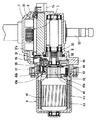
図1は、電動パワーステアリング装置1の軸方向断面図である。図2は、電動パワーステアリング装置1の入力軸51及び出力軸52に沿った軸方向断面図である。図3は、図2における制御部3及び支持部材8を示す軸方向断面図である。図4の(a)は、制御部3の正面図であり、(b)は、図4(a)の側面図である。図5は、電動パワーステアリング装置1の一部の径方向断面図である。図6は、図1の一部分の拡大図である。図7は、図6のVII−VII矢視断面図である。
【0018】
本実施形態の電動パワーステアリング装置1は、車両の車室内に設けられ、図1及び図2に示すように、トルクセンサ2、制御部3、電動モータ4及び動力伝達部5から構成されており、トルクセンサ2と制御部3と動力伝達部5とがハウジング6及びカバー7内に設けられ、電動モータ4がヨーク49内に設けられている。
【0019】
操舵軸は、入力軸51、出力軸52及びトーションバー53から構成されており、ベアリング11、12、13、14により支持されている。
【0020】
入力軸51は、図2に示すように、ステアリング(図示しない)に連結され、出力軸52の内周に軸受14を介して相対回転可能に設けられている。
【0021】
出力軸52は、入力軸51と同軸上に設けられ、トーションバー53を介して入力軸51と相対回転可能に連結されている。
【0022】
トーションバー53は、入力軸51と出力軸52との中空部に挿入されて、両端がそれぞれピン9、10を介して入力軸51と出力軸52とに連結され、ステアリングの操作により入力軸51に操舵力が付与されると、自身に捩じれが生じることで、入力軸51と出力軸52とが相対回転する。
【0023】
トルクセンサ2は、ステアリングに加えられる操舵力を検出するものであり、磁石21、磁気ヨーク22、集磁リング23及び磁気センサ24から構成されている。
【0024】
磁石21は、リング状であって、ステアリングと連結される入力軸51の外周に磁石固定部21aを介して圧入固定されており、周方向にN極とS極とが交互に着磁されている。
【0025】
磁気ヨーク22は、磁石21の極数(N極又はS極)と同数の磁極爪(図示しない)が全周に等間隔に設けられた環状体で、2個1組で構成され、磁石21の外周に一定のエアギャップを有して同心に設けられている。なお、1組の磁気ヨーク22は、互いの磁極爪が周方向にずれて交互に配置されるように位置決めされている。
【0026】
集磁リング23は、磁気ヨーク22と同様に2個1組で構成され、磁気ヨーク22の外周に近接して設けられる。この集磁リング23は、後述する円筒部材8の内周面に集磁リング固定部23bを介して一体成形されている。また、集磁リング23には、周方向の一部分に平板状の集磁部23aが設けられ、この集磁部23aは、互いの集磁部23aが軸方向に対向して設けられている。
【0027】
磁気センサ24は、軸方向に対向する集磁部23a同士の間に設けられ、両集磁部23a間に発生する磁束密度を検出し、その検出した磁束密度を電気信号(例えば電圧信号)に変換して出力する。この磁気センサ24は、例えばホールICであり、円筒部材8に集磁リング固定部23bを介して固定され、ホールICターミナル24aが軸方向のステアリング側に直角に折り曲げられ、制御部3の制御基板31に半田により接続されている。
【0028】
制御部3は、上述のトルクセンサ2で検出された操舵トルクに基づいて、電動モータ4へ流れる電流をデューティー制御するものである。
【0029】
制御基板31は、板状であって、図4(a)に示すように、その平面形状が長方形と半円形とを組み合わせた形状を呈しており、半円形側の中央部に入力軸51を通すための丸孔31aが設けられている。また、制御基板31には、電動モータ4のモータターミナル41が接続される貫通孔31bが設けられている。
【0030】
スイッチングトランジスタ32は、電動モータ4に流れる電流をデューティー制御するためのものであって、支持部材8の斜面部82に直接ネジ止め等により固定されている。このスイッチングトランジスタ32は、図2に示すように、スイッチングトランジスタ32の側方に取り出されたターミナルが軸方向のステアリング側に曲げられて制御基板31に半田により接続されている。
【0031】
制御基板31には、図3及び図4(a)に示すように、制御素子33、リレー34、35及びコンデンサ36が直接基板上に組み付けられている。また、制御基板31には、トルクセンサ2からの端子が接続され、操舵力が入力される。
【0032】
制御素子33は、マイクロコンピュータ等の素子であり、トルクセンサ2からの操舵力に応じて、電動モータ4に流す電流を決定し、且つスイッチングトランジスタ32をデューティー制御するための信号を生成する。リレー34は、イグニッションスイッチ(図示しない)がオン及びオフされることで電動モータ4へ流れる電流を通電及び遮断させるものである。リレー35は、電動モータ4の駆動回路がフェ−ルした際に、ステアリングの入力に対して電動モータ4が回転されることで、電動モータ4が発電しないように電動モータ4とスイッチングトランジスタ32との間に流れる電流を遮断させるものである。コンデンサ36は、電源電圧の変動を抑制するものである。
【0033】
電動モータ4は、上述した制御部3で決定されたステアリングの操舵力を補助するための操舵補助力を出力軸52に付与するものであり、磁性体のヨーク49の内周にマグネット48を有する界磁、この界磁の内周に回転自在に支持されたアーマチャ47及びこのアーマチャ47に設けられたコンミテータ46に摺接するブラシ43等から構成される直流モータである。また、ブラシ43をブラシホルダ43a内に設けられたスプリング44により、内径方向に付勢することで、ブラシ43をコンミテータ46に摺接させている。また、ブラシホルダ43aは、ゴムマウント43bによってフローティングされている。なお、このゴムマウント43bは、ブラシ43がコンミテータ46の外周面上を摺動する時に発生する振動を吸収するものである。さらに、電動モータ4は、図5に示すように、ヨーク49の開口端面がハウジング6の側面に当接して組み付けられ、ボルト18によりフレームエンド70に固定されている。
【0034】
また、電動モータ4は、図1、図6及び図7に示すように、第1のピグテール42を介してブラシ43と電気的に接続され、ブラシホルダ43aに固定される第2のターミナルを成す金属製のモータターミナル41を具備し、このモータターミナル41は、ブラシホルダ43aにかしめによって固定されているプレート(図示しない)と一体成形されている。また、モータターミナル41の他端は、給電線と網線とを成す第2のピグテール19の一端とかしめにより接合されている。
【0035】
第2のピグテール19は、可撓性の電気伝導材料である銅から成り、一端が上述のモータターミナル41と、他端が第1のターミナルを成す基板ターミナル37とそれぞれかしめによって接合されている。
【0036】
基板ターミナル37は、長手方向が制御部3と直交するように樹脂部材37aに固定されており、一端が制御基板31と半田により接合され、他端が第2のピグテール19の他端と接合されている。
【0037】
樹脂部材37aは、制御基板31に接続される基板ターミナル37を位置決めするために固定しており、樹脂によって成形され、ネジによってハウジング6の内壁に当接しているエンドフレーム70に固定されている。
【0038】
そして、制御部3で決定され、スイッチングトランジスタ32によりデューティー制御された電流が基板ターミナル37、第2のピグテール19、モータターミナル41、プレート、第1のピグテール42及びブラシ43を介してアーマチャ47に供給される。
【0039】
動力伝達部5は、上述した電動モータ4から出力される操舵補助力を転舵輪側へ伝達するものであり、入力軸51、出力軸52、トーションバー53、ウォームホイール54及びウォームギヤ55から構成されている。
【0040】
ウォームギヤ55は、図1に示すように、電動モータ4のアーマチャシャフト45に圧入固定された伝達部材16を介してアーマチャシャフト45の回転力が伝達されることで回転する。
【0041】
ウォームホイール54は、図2に示すように、出力軸52の外周に固定され、ウォームホイール54の外周がウォームギヤ55と噛み合っており、ウォームギヤ55が回転することで周方向に回転する。
【0042】
ハウジング6は、外枠を成し、動力伝達部5を収容するためのものであって、アルミニウム製であり、ハウジング6内に支持部材8が固定される。このハウジング6は、ベアリング12を介して出力軸52を回転自在に支持している。
【0043】
カバー7は、外枠を成し、ハウジング6と同様にアルミニウム製であり、ハウジング6内にトルクセンサ2、制御部3及び動力伝達部5を収容するために設けられたハウジング6の開口端を塞ぐためのものであって、入力軸51を支持するベアリング13を固定する。また、カバー7は、支持部材8をハウジング6の内壁と当接するように支持部材8を押し付ける。また、カバー7は、図5に示すように、ハウジング6に設けられたカバー固定部71a、71bに固定される。このカバー固定部71aは、ハウジング6の外壁とヨーク49の外壁とが接する線に近接する位置に設けられる。カバー固定部71bは、カバー固定部71aと軸心の対称位置に設けられる。
【0044】
なお、特許請求の範囲の外枠とは、本実施形態でのハウジング6とカバー7とエンドフレーム70とを合わせたものに相当する。
【0045】
支持部材8は、アルミニウム製であって、円筒形状と直方体形状とを組み合わせた形状を呈しており、ハウジング6とカバー7との間の空間内に設けられる。また、支持部材8は、図2に示すように、軸方向のステアリング側の面で制御部3を支持し、反ステアリング側の面でハウジング6の内壁に固定される。さらに、支持部材8は、内周面に集磁リング23が設けられた集磁リング固定部23aが設けられている。また、支持部材8は、ベアリング11を介して出力軸52を軸支している。さらに、支持部材8は、ハウジング6の内壁と当接する当接部81を有している。この当接部81の支持部材8のスイッチングトランジスタ32が固定される面の裏面側がハウジング6と当接している。また、支持部材8には、図4(b)に示すように、バッテリ(図示しない)との接続するための電源用ターミナルと、車速信号等を入力するための信号用ターミナルとを有するコネクタ15が固定されている。
【0046】
また、支持部材8は、図3に示すように、制御部3が支持された状態で、ハウジング6とカバー7との間の空間内に収納される。
【0047】
[第1実施形態の効果]
本実施形態の電動パワーステアリング装置1のモータターミナル41は、ゴムマウント43bによりフローティングされているブラシホルダ43aに固定されているため、ブラシ43の振動が伝達されてしまうが、可撓性のある第2のピグテール19を介して制御基板31に接続されることから、モータターミナル41に伝達される振動を第2のピグテール19によって吸収させることができる。そのため、モータターミナル41に伝達される振動が制御基板31に伝達されることを抑制できる。これにより、ブラシ43で発生する振動がハウジング6に伝達されることを抑制できるため、騒音が発生することを抑制できる。さらに、制御基板31の基板ターミナル37と半田により接続される接続部分に応力が加わることを抑制できるため、制御基板31と基板ターミナル37とを接続する半田の破裂を抑制できる。よって、電動パワーステアリング装置1の信頼性の向上を図ることができる。
【0048】
また、基板ターミナル37は、エンドフレーム70にネジにより固定される樹脂部材37aに固定されることで、位置決めされているため、基板ターミナル37を制御基板31に接続させ易くすることができる。
【0049】
さらに、第2のピグテール19の一端は、モータターミナル41と、他端は、基板ターミナル37とかしめにより接合させることで、安価で、且つ容易に制御部3と電動モータ4とを電気的に接続させることができる。
【0050】
[第2実施形態]
図8は、電動パワーステアリング装置1の軸方向断面図の拡大図である。図9は、図8のIX−IX矢視断面図である。ここでは、第1実施形態と同様な箇所は省略し、相違する箇所についてのみ説明する。
【0051】
本実施形態では、図8及び図9に示すように、第2のピグテール19とモータターミナル41とを給電用コネクタ60を介して制御部3と電動モータ4とを電気的に接続させている。
【0052】
第2のピグテール19の他端は、給電用コネクタ60とかしめによって接合されている。また、給電用コネクタ60は、モータターミナル41に嵌め込まれることによって電気的に接続されている。なお、樹脂部材37aは、支持部材8にネジによって固定されている。
【0053】
本実施形態では、第2のピグテール19の他端が給電用コネクタ60を介してモータターミナル41と電気的に接続されていることから、給電用コネクタ60をモータターミナル41に嵌合することで、接合させることができるため、半田付けする必要がない。これにより、組み付け性の向上を図ることができる。
【0054】
[第3実施形態]
図10は、電動パワーステアリング装置1の軸方向断面図である。図11は、図10のI−I矢視断面図である。ここでは、第1実施形態と同様な箇所は省略し、相違する箇所についてのみ説明する。
【0055】
本実施形態では、図10及び図11に示すように、第1及び第2実施形態での樹脂部材37aを用いずに、第2のピグテール19を例えばワックス等の熱溶融性部材によって固化することで、剛性を高くし、且つ基板ターミナル37を位置決めしている。また、制御基板31と基板ターミナル37とを接続した後に、制御部3と電動モータ4との間を通電させることで、第2のピグテール19に固化されている熱溶融性部材が軟化する。そして、この軟化した熱溶融性部材を吸引して除去する。これにより、第2のピグテール19の剛性を低くすることができるため、モータターミナル41の振動を第2のピグテール19によって吸収させることができる。
【0056】
なお、本実施形態では、制御部3と電動モータ4との間を通電させることで、第2のピグテール19に固化されている熱溶融性部材を軟化させているが、通電電流を高くして熱溶融性部材を気化させてもよい。これにより、第2のピグテール19の剛性をより低くすることができる。さらに、熱溶融性部材を気化させることで、熱溶融性部材を吸引して除去する必要がなくなる。
【0057】
なお、以上説明した第1から第3の実施形態では、制御部3と電動モータ4とを基板ターミナル37、第2のピグテール19及びモータターミナル41によって電気的に接続させているが、第2のピグテール19のみで電気的に接続させていてもよい。
【0058】
なお、第1及び第2実施形態では、第2のピグテール19を用いているが、被覆線等の可撓性のある電気伝導材料であればよい。
【図面の簡単な説明】
【図1】電動パワーステアリング装置の軸方向断面図である。(第1実施形態)
【図2】電動パワーステアリング装置の入力軸及び出力軸に沿った軸方向断面図である。(第1実施形態)
【図3】図2における制御部及び支持部材を示す軸方向断面図である。(第1実施形態)
【図4】(a)は、制御部の正面図であり、(b)は、(a)の側面図である。(第1実施形態)
【図5】電動パワーステアリング装置の一部の径方向断面図である。(第1実施形態)
【図6】図1の一部分の拡大図である。(第1実施形態)
【図7】図6のVII−VII矢視断面図である。(第1実施形態)
【図8】電動パワーステアリング装置の軸方向断面図の拡大図である。(第2実施形態)
【図9】図8のIX−IX矢視断面図である。(第2実施形態)
【図10】電動パワーステアリング装置の軸方向断面図の拡大図である。(第3実施形態)
【図11】図10のI−I矢視断面図である。(第3実施形態)
【符号の説明】
1…電動パワーステアリング装置、
2…トルクセンサ、
3…制御部、
4…電動モータ、
5…動力伝達部、
6…ハウジング、
7…カバー、
8…支持部材、
19…第2のピグテール、
37…基板ターミナル、
37a…樹脂部材、
41…モータターミナル、
60…給電用コネクタ。[0001]
BACKGROUND OF THE INVENTION
The present invention relates to an electric power steering device that assists the steering force of a vehicle steering.
[0002]
[Prior art]
Conventionally, an electric power steering apparatus includes a torque sensor that detects a steering torque of a steering, a control unit that determines a steering assist force based on the steering torque detected by the torque sensor, and a steering assist force that is determined by the control unit. And a power transmission unit that transmits the steering assist force output by the electric motor to the steered wheel side. In addition, a power supply line for connecting the control unit and the electric motor and supplying the electric motor to the electric motor is provided through the outside (see, for example, Patent Document 1).
[0003]
[Patent Document 1]
JP-A-8-175403 (Figs. 1 and 4)
[0004]
[Problems to be solved by the invention]
However, since the power supply line described in Patent Document 1 is a wire harness and is arranged through the outside, when the control unit performs duty control on the current flowing to the electric motor, an electromagnetic wave is generated from the power supply line. For example, noise is generated in a radio receiver of a vehicle. Therefore, by accommodating the power supply line in the housing that forms the outer wall of the electric power steering apparatus, it is possible to suppress adverse effects on external devices due to electromagnetic waves from the power supply line, and it is not necessary to use a wire harness for the power supply line. As a result, it is conceivable to connect the motor terminal of a highly rigid electric motor directly to the control board of the control unit. However, if the motor terminal is directly connected to the control board by soldering or the like, vibration generated from the brush of the electric motor Is transmitted to the housing via the motor terminal and the control board, and noise is generated. Further, the brush holder to which the motor terminal is fixed vibrates due to the vibration of the vehicle, which is transmitted to the joint portion between the control board and the motor terminal via the motor terminal, and stress is applied, resulting in poor jointing. There is a problem.
[0005]
The present invention has been made in view of the above problems, and an object thereof is to provide an electric power steering device that can suppress vibration from an electric motor from being transmitted to a control unit.
[0006]
[Means for Solving the Problems]
In order to solve the above-mentioned problem, in claim 1, based on a steering force applied to the steering shaft, a control unit that determines a steering assist force that assists the steering force, and a steering assist force that is determined by the control unit. An electric motor for applying to the steering shaft, a brush for supplying electric power to the electric motor, a brush holder for holding the brush, and an outer frame for accommodating the control unit and the electric motor. The brush holder is floated by a rubber mount, is electrically connected between the control unit and the brush of the electric motor, and supplies current to the electric motor. The feeder lines are all provided in the outer frame and are flexible.
[0007]
With this configuration, since the power supply line connected between the control unit and the electric motor is flexible, and the brush holder is floated by the rubber mount , vibration from the electric motor is supplied. It can be absorbed by electric wires. Thereby, it can suppress that the vibration from an electric motor is transmitted to a control part.
[0008]
According to the first aspect of the present invention , one end of the power supply line is joined to a first terminal connected to the control board of the control unit, and the first terminal is positioned and fixed to a resin member fixed to the outer frame. It is characterized by that.
[0009]
With this configuration, since the first terminal is positioned and fixed to the resin member fixed to the outer frame, the first terminal can be easily joined to the control board.
[0010]
Further, in claim 1 , the other end of the power supply line is joined to the second terminal connected to the electric motor, and the power supply line is joined only to the first terminal or the second terminal by caulking. It is a feature.
[0011]
With this configuration, one end of the power supply line and the first terminal or the other end of the power supply line and the second terminal can be joined at low cost and easily.
[0014]
According to a second aspect of the present invention , the power supply line is a conductive wire made of only a net-like electrically conductive material, and is solidified by a heat-meltable member. The heat-meltable member is softened by current flowing through the power supply line. It is characterized by doing.
[0015]
With this configuration, the power supply line made only of the flexible electrical transmission material is solidified by the heat-meltable member, so that the rigidity of the power supply line can be increased and positioning with the control unit can be performed. It is possible to facilitate bonding to the control board. Further, since the heat-meltable member is softened by the current flowing through the power supply line, the rigidity of the power supply line can be reduced, and the vibration from the electric motor can be absorbed by the power supply line.
[0016]
DETAILED DESCRIPTION OF THE INVENTION
Hereinafter, embodiments shown in the drawings will be described.
[0017]
[First Embodiment]
FIG. 1 is an axial sectional view of the electric power steering apparatus 1. FIG. 2 is an axial cross-sectional view along the
[0018]
The electric power steering apparatus 1 according to the present embodiment is provided in a vehicle interior of a vehicle and includes a
[0019]
The steering shaft includes an
[0020]
As shown in FIG. 2, the
[0021]
The
[0022]
The
[0023]
The
[0024]
The
[0025]
The
[0026]
Similar to the
[0027]
The
[0028]
The
[0029]
The
[0030]
The switching
[0031]
As shown in FIGS. 3 and 4 (a), the
[0032]
The
[0033]
The electric motor 4 applies a steering assist force to assist the steering force determined by the
[0034]
Further, as shown in FIGS. 1, 6 and 7, the electric motor 4 is electrically connected to the
[0035]
The
[0036]
The
[0037]
The
[0038]
Then, the current determined by the
[0039]
The
[0040]
As shown in FIG. 1, the
[0041]
As shown in FIG. 2, the
[0042]
The
[0043]
The
[0044]
The outer frame in the claims corresponds to a combination of the
[0045]
The
[0046]
Further, as shown in FIG. 3, the
[0047]
[Effect of the first embodiment]
Since the
[0048]
Further, since the
[0049]
Furthermore, one end of the
[0050]
[Second Embodiment]
FIG. 8 is an enlarged view of an axial sectional view of the electric power steering apparatus 1. 9 is a cross-sectional view taken along arrow IX-IX in FIG. Here, the same parts as those in the first embodiment are omitted, and only different parts will be described.
[0051]
In the present embodiment, as shown in FIGS. 8 and 9, the
[0052]
The other end of the
[0053]
In the present embodiment, since the other end of the
[0054]
[Third Embodiment]
FIG. 10 is an axial cross-sectional view of the electric power steering apparatus 1. FIG. 11 is a cross-sectional view taken along the line II in FIG. Here, the same parts as those in the first embodiment are omitted, and only different parts will be described.
[0055]
In this embodiment, as shown in FIGS. 10 and 11, the
[0056]
In this embodiment, the heat-meltable member solidified in the
[0057]
In the first to third embodiments described above, the
[0058]
In the first and second embodiments, the
[Brief description of the drawings]
FIG. 1 is an axial sectional view of an electric power steering apparatus. (First embodiment)
FIG. 2 is an axial sectional view taken along an input shaft and an output shaft of the electric power steering apparatus. (First embodiment)
FIG. 3 is an axial sectional view showing a control unit and a support member in FIG. 2; (First embodiment)
4A is a front view of a control unit, and FIG. 4B is a side view of FIG. 4A. (First embodiment)
FIG. 5 is a radial cross-sectional view of a part of the electric power steering apparatus. (First embodiment)
FIG. 6 is an enlarged view of a portion of FIG. (First embodiment)
7 is a cross-sectional view taken along arrow VII-VII in FIG. 6; (First embodiment)
FIG. 8 is an enlarged view of an axial sectional view of the electric power steering apparatus. (Second Embodiment)
9 is a cross-sectional view taken along arrow IX-IX in FIG. (Second Embodiment)
FIG. 10 is an enlarged view of an axial sectional view of the electric power steering apparatus. (Third embodiment)
11 is a cross-sectional view taken along the line II in FIG. (Third embodiment)
[Explanation of symbols]
1 ... Electric power steering device,
2 ... Torque sensor,
3 ... control part,
4 ... Electric motor,
5 ... Power transmission part,
6 ... Housing,
7 ... Cover,
8: Support member,
19 ... The second pigtail,
37 ... Board terminal,
37a ... resin member,
41 ... Motor terminal,
60: Power feeding connector.
Claims (2)
前記制御部は、前記操舵補助力に応じて前記電動モータに流れる電流を制御し、前記ブラシホルダはゴムマウントによりフローティングされており、前記制御部と前記電動モータのブラシとの間に電気的に接続され、且つ前記電動モータへ前記電流を供給するための給電線は、全てが前記外枠内に設けられ、且つ可撓性であり、
前記給電線の一端は、前記制御部の制御基板に接続された第1のターミナルと接合され、
前記第1のターミナルは、前記外枠に固定される樹脂部材に位置決め固定されており、
前記給電線の他端は、前記電動モータに接続された第2のターミナルと接合され、前記給電線は、前記第1のターミナルもしくは前記第2のターミナルとかしめのみによって接合されることを特徴とする電動パワーステアリング装置。A control unit for determining a steering assist force for assisting the steering force based on a steering force applied to the steering shaft; and an electric motor for applying the steering assist force determined by the control unit to the steering shaft; A brush for supplying power to the electric motor, a brush holder for holding the brush, and an outer frame for housing the control unit and the electric motor,
The control unit controls a current flowing through the electric motor according to the steering assist force, the brush holder is floated by a rubber mount, and is electrically connected between the control unit and the brush of the electric motor. is connected, is and feed line for supplying the current to the electric motor, all provided within the outer frame, Ri and flexible der,
One end of the power supply line is joined to a first terminal connected to the control board of the control unit,
The first terminal is positioned and fixed to a resin member fixed to the outer frame,
The other end of the power supply line is joined to a second terminal connected to the electric motor, and the power supply line is joined only by caulking to the first terminal or the second terminal. Electric power steering device.
前記制御部は、前記操舵補助力に応じて前記電動モータに流れる電流を制御し、前記ブラシホルダはゴムマウントによりフローティングされており、前記制御部と前記電動モータのブラシとの間に電気的に接続され、且つ前記電動モータへ前記電流を供給するための給電線は、全てが前記外枠内に設けられ、且つ可撓性であり、
前記給電線は、網状の電気伝導材料のみから成る導線であって、熱溶融性部材によって固化されており、前記熱溶融性部材は、前記給電線に前記電流が流れることで、軟化することを特徴とする電動パワーステアリング装置。 A control unit for determining a steering assist force for assisting the steering force based on a steering force applied to the steering shaft; and an electric motor for applying the steering assist force determined by the control unit to the steering shaft; A brush for supplying power to the electric motor, a brush holder for holding the brush, and an outer frame for housing the control unit and the electric motor,
The control unit controls a current flowing through the electric motor according to the steering assist force, the brush holder is floated by a rubber mount, and is electrically connected between the control unit and the brush of the electric motor. All of the feeder lines that are connected and for supplying the electric current to the electric motor are provided in the outer frame and are flexible,
The power supply line is a conductive wire made of only a net-like electrically conductive material, and is solidified by a heat-meltable member, and the heat-meltable member softens when the current flows through the power supply line. An electric power steering device.
Priority Applications (1)
| Application Number | Priority Date | Filing Date | Title |
|---|---|---|---|
| JP2002351443A JP4028366B2 (en) | 2002-12-03 | 2002-12-03 | Electric power steering device |
Applications Claiming Priority (1)
| Application Number | Priority Date | Filing Date | Title |
|---|---|---|---|
| JP2002351443A JP4028366B2 (en) | 2002-12-03 | 2002-12-03 | Electric power steering device |
Publications (2)
| Publication Number | Publication Date |
|---|---|
| JP2004182079A JP2004182079A (en) | 2004-07-02 |
| JP4028366B2 true JP4028366B2 (en) | 2007-12-26 |
Family
ID=32753356
Family Applications (1)
| Application Number | Title | Priority Date | Filing Date |
|---|---|---|---|
| JP2002351443A Expired - Fee Related JP4028366B2 (en) | 2002-12-03 | 2002-12-03 | Electric power steering device |
Country Status (1)
| Country | Link |
|---|---|
| JP (1) | JP4028366B2 (en) |
Cited By (1)
| Publication number | Priority date | Publication date | Assignee | Title |
|---|---|---|---|---|
| CN103502081A (en) * | 2011-05-11 | 2014-01-08 | 三菱电机株式会社 | Electric power steering device |
Families Citing this family (10)
| Publication number | Priority date | Publication date | Assignee | Title |
|---|---|---|---|---|
| CN100511965C (en) * | 2004-11-22 | 2009-07-08 | 株式会社日立制作所 | Motor control apparatus, power steering apparatus and brake control apparatus |
| JP5003005B2 (en) * | 2006-04-11 | 2012-08-15 | 日本精工株式会社 | Electric power steering device |
| JP5011801B2 (en) * | 2006-04-11 | 2012-08-29 | 日本精工株式会社 | Electric power steering device |
| EP2006185B1 (en) | 2006-04-11 | 2016-07-20 | NSK Ltd. | Electric power steering device and method of assembling the same |
| JP5186788B2 (en) * | 2006-04-11 | 2013-04-24 | 日本精工株式会社 | Electric power steering device |
| JP5003007B2 (en) * | 2006-04-11 | 2012-08-15 | 日本精工株式会社 | Electric power steering device |
| JP5003006B2 (en) * | 2006-04-11 | 2012-08-15 | 日本精工株式会社 | Electric power steering device |
| JP5252939B2 (en) * | 2008-02-07 | 2013-07-31 | 株式会社ジェイテクト | Motor control device and vehicle steering apparatus provided with the same |
| WO2012073412A1 (en) * | 2010-12-02 | 2012-06-07 | 日本精工株式会社 | Electric power steering device |
| EP2574521B1 (en) * | 2010-12-07 | 2016-11-16 | NSK Ltd. | Electric power steering device |
-
2002
- 2002-12-03 JP JP2002351443A patent/JP4028366B2/en not_active Expired - Fee Related
Cited By (2)
| Publication number | Priority date | Publication date | Assignee | Title |
|---|---|---|---|---|
| CN103502081A (en) * | 2011-05-11 | 2014-01-08 | 三菱电机株式会社 | Electric power steering device |
| CN103502081B (en) * | 2011-05-11 | 2016-02-10 | 三菱电机株式会社 | Driven steering device |
Also Published As
| Publication number | Publication date |
|---|---|
| JP2004182079A (en) | 2004-07-02 |
Similar Documents
| Publication | Publication Date | Title |
|---|---|---|
| JP3614380B2 (en) | Electric power steering device | |
| US6851509B2 (en) | Easy-to-assemble structure of electric power steering device | |
| JP6639962B2 (en) | Electric drive device and electric power steering device | |
| JP3951873B2 (en) | Electric power steering device | |
| JP4623125B2 (en) | Electric motor device for electric power steering and electric power steering device | |
| JP5248814B2 (en) | Motor drive device and inspection method thereof | |
| JP5603045B2 (en) | Motor device for electric power steering device | |
| JP4028366B2 (en) | Electric power steering device | |
| JP3622362B2 (en) | Electric power steering device | |
| JP5619279B2 (en) | Electric power steering device | |
| JP6038383B2 (en) | Motor drive device | |
| JP2010028925A (en) | Electric motor and motor for electric power steering device | |
| JP3956896B2 (en) | Electric motor drive device | |
| JP5563513B2 (en) | Electric power steering device | |
| JP4582182B2 (en) | Electric power steering device | |
| JP3922196B2 (en) | Electric power steering device | |
| JP3888148B2 (en) | Electric power steering device | |
| JP4652924B2 (en) | Motor manufacturing method and motor | |
| JP3918709B2 (en) | Electric power steering device | |
| JP2004155253A (en) | Driving device | |
| JP2008206346A (en) | Dc motor and commutator manufacturing method | |
| JP3922143B2 (en) | Electric power steering device | |
| JP3794362B2 (en) | Electric power steering device | |
| JP4549582B2 (en) | Motor and intermediate connector manufacturing method of motor | |
| JP2000078798A (en) | Motor and electric power steering apparatus |
Legal Events
| Date | Code | Title | Description |
|---|---|---|---|
| A621 | Written request for application examination |
Free format text: JAPANESE INTERMEDIATE CODE: A621 Effective date: 20050125 |
|
| A131 | Notification of reasons for refusal |
Free format text: JAPANESE INTERMEDIATE CODE: A131 Effective date: 20060822 |
|
| A521 | Request for written amendment filed |
Free format text: JAPANESE INTERMEDIATE CODE: A523 Effective date: 20061017 |
|
| A131 | Notification of reasons for refusal |
Free format text: JAPANESE INTERMEDIATE CODE: A131 Effective date: 20070130 |
|
| A521 | Request for written amendment filed |
Free format text: JAPANESE INTERMEDIATE CODE: A523 Effective date: 20070315 |
|
| TRDD | Decision of grant or rejection written | ||
| A01 | Written decision to grant a patent or to grant a registration (utility model) |
Free format text: JAPANESE INTERMEDIATE CODE: A01 Effective date: 20071002 |
|
| A61 | First payment of annual fees (during grant procedure) |
Free format text: JAPANESE INTERMEDIATE CODE: A61 Effective date: 20071011 |
|
| FPAY | Renewal fee payment (event date is renewal date of database) |
Free format text: PAYMENT UNTIL: 20101019 Year of fee payment: 3 |
|
| R150 | Certificate of patent or registration of utility model |
Ref document number: 4028366 Country of ref document: JP Free format text: JAPANESE INTERMEDIATE CODE: R150 Free format text: JAPANESE INTERMEDIATE CODE: R150 |
|
| FPAY | Renewal fee payment (event date is renewal date of database) |
Free format text: PAYMENT UNTIL: 20111019 Year of fee payment: 4 |
|
| FPAY | Renewal fee payment (event date is renewal date of database) |
Free format text: PAYMENT UNTIL: 20121019 Year of fee payment: 5 |
|
| FPAY | Renewal fee payment (event date is renewal date of database) |
Free format text: PAYMENT UNTIL: 20121019 Year of fee payment: 5 |
|
| FPAY | Renewal fee payment (event date is renewal date of database) |
Free format text: PAYMENT UNTIL: 20131019 Year of fee payment: 6 |
|
| R250 | Receipt of annual fees |
Free format text: JAPANESE INTERMEDIATE CODE: R250 |
|
| R250 | Receipt of annual fees |
Free format text: JAPANESE INTERMEDIATE CODE: R250 |
|
| R250 | Receipt of annual fees |
Free format text: JAPANESE INTERMEDIATE CODE: R250 |
|
| R250 | Receipt of annual fees |
Free format text: JAPANESE INTERMEDIATE CODE: R250 |
|
| S111 | Request for change of ownership or part of ownership |
Free format text: JAPANESE INTERMEDIATE CODE: R313111 |
|
| R360 | Written notification for declining of transfer of rights |
Free format text: JAPANESE INTERMEDIATE CODE: R360 |
|
| R360 | Written notification for declining of transfer of rights |
Free format text: JAPANESE INTERMEDIATE CODE: R360 |
|
| R371 | Transfer withdrawn |
Free format text: JAPANESE INTERMEDIATE CODE: R371 |
|
| S111 | Request for change of ownership or part of ownership |
Free format text: JAPANESE INTERMEDIATE CODE: R313115 |
|
| R350 | Written notification of registration of transfer |
Free format text: JAPANESE INTERMEDIATE CODE: R350 |
|
| R250 | Receipt of annual fees |
Free format text: JAPANESE INTERMEDIATE CODE: R250 |
|
| R250 | Receipt of annual fees |
Free format text: JAPANESE INTERMEDIATE CODE: R250 |
|
| R250 | Receipt of annual fees |
Free format text: JAPANESE INTERMEDIATE CODE: R250 |
|
| R250 | Receipt of annual fees |
Free format text: JAPANESE INTERMEDIATE CODE: R250 |
|
| LAPS | Cancellation because of no payment of annual fees |