JP4027204B2 - Recording apparatus, recording method, and data processing apparatus - Google Patents
Recording apparatus, recording method, and data processing apparatus Download PDFInfo
- Publication number
- JP4027204B2 JP4027204B2 JP2002308373A JP2002308373A JP4027204B2 JP 4027204 B2 JP4027204 B2 JP 4027204B2 JP 2002308373 A JP2002308373 A JP 2002308373A JP 2002308373 A JP2002308373 A JP 2002308373A JP 4027204 B2 JP4027204 B2 JP 4027204B2
- Authority
- JP
- Japan
- Prior art keywords
- recording
- color
- dots
- nozzle
- recorded
- Prior art date
- Legal status (The legal status is an assumption and is not a legal conclusion. Google has not performed a legal analysis and makes no representation as to the accuracy of the status listed.)
- Expired - Fee Related
Links
Images


Classifications
-
- B—PERFORMING OPERATIONS; TRANSPORTING
- B41—PRINTING; LINING MACHINES; TYPEWRITERS; STAMPS
- B41J—TYPEWRITERS; SELECTIVE PRINTING MECHANISMS, i.e. MECHANISMS PRINTING OTHERWISE THAN FROM A FORME; CORRECTION OF TYPOGRAPHICAL ERRORS
- B41J2/00—Typewriters or selective printing mechanisms characterised by the printing or marking process for which they are designed
- B41J2/005—Typewriters or selective printing mechanisms characterised by the printing or marking process for which they are designed characterised by bringing liquid or particles selectively into contact with a printing material
- B41J2/01—Ink jet
- B41J2/21—Ink jet for multi-colour printing
- B41J2/2132—Print quality control characterised by dot disposition, e.g. for reducing white stripes or banding
- B41J2/2139—Compensation for malfunctioning nozzles creating dot place or dot size errors
-
- B—PERFORMING OPERATIONS; TRANSPORTING
- B41—PRINTING; LINING MACHINES; TYPEWRITERS; STAMPS
- B41J—TYPEWRITERS; SELECTIVE PRINTING MECHANISMS, i.e. MECHANISMS PRINTING OTHERWISE THAN FROM A FORME; CORRECTION OF TYPOGRAPHICAL ERRORS
- B41J2/00—Typewriters or selective printing mechanisms characterised by the printing or marking process for which they are designed
- B41J2/005—Typewriters or selective printing mechanisms characterised by the printing or marking process for which they are designed characterised by bringing liquid or particles selectively into contact with a printing material
- B41J2/01—Ink jet
- B41J2/21—Ink jet for multi-colour printing
Abstract
Description
【0001】
【発明の属する技術分野】
本発明は、複数の記録素子を配列した記録ヘッドを用いて記録を行う記録装置、および記録方法、並びにそのデータ処理装置に関する。本発明は特に、複数のノズルを配列した記録ヘッドを用い、ノズルからインクを吐出して記録を行うインクジェットプリンタ等の記録装置等に関する。
【0002】
【従来の技術】
記録ヘッドに配列されたノズルからインクを吐出して記録媒体に記録を行うインクジェット方式の記録装置は、近年において、プリンタ、FAX、複写機等に多く適用されてきている。特に複数の色のインクを用いてカラー画像を記録可能なカラープリンタにおいてはその高画質化が進むことで著しい伸びを示しているといえる。
【0003】
また、記録装置においては、高画質化の一方で、高速化も重要な要素であり、ヘッドの液滴吐出駆動周波数の高速化と共に、記録ヘッドに配列されるノズル数の増加による高速化が進みつつある。
【0004】
しかしながら、インクジェットヘッドにおいては、製造時に記録ヘッドのノズル内に入ったゴミや、長期間の使用によるノズルの劣化、インクを吐出させるための素子の劣化等が原因となって、いわゆる「不吐出」というインク滴が吐出できなくなる状況が発生する場合がある。後者が原因となる場合は、特に記録装置の使用期間中に偶発的に不吐出が発生する可能性もある。
【0005】
また、完全に不吐出の状態とならずに、インク滴の吐出方向が所望の方向より大きく偏った状態(以下、「吐出のよれ」とも称する)や、インク滴の吐出量が所望の量より大きく異なった状態(以下、「ドロップ径のばらつき」とも称す)となる場合もあった。このような、記録に用いた場合に記録画像の品質を大きく低下させる程に劣化したノズルについては、記録を行うノズルに相当しない状態であり、以下、「不吐出」と含めて説明する。
【0006】
このような不吐出等は、製造環境等の改善により、発生する頻度を抑えることができ、従来は大きな問題ではなかった。しかし、前述のように高速化のために記録ヘッドに配列するノズル数を多くした場合、無視できない問題となる。
【0007】
特に、不吐出状態のノズルを含まない記録ヘッドや、不吐出が発生しにくい良好な記録ヘッドを製造するためには、製造上のコストアップを招き、結果として記録ヘッドが高価になってしまう。
【0008】
【発明が解決しようとする課題】
これらの不吐出等が発生すると、画像上に白すじ等の欠陥が発生する。このような白すじを補完するため、記録ヘッドを複数回走査して記録を行う分割印字方式を利用し、白すじとなる部分を他の正常なノズルで補完して記録する等の技術が、例えば、特開平5−301427号公報や特開平6−79956号公報等で提案されている。
【0009】
しかしながら、上述したような記録の高速化を達成するためには、1回の走査で印字を完成させる、所謂1パス印字を行うことが好ましいが、この1パス印字においては、不吐出で記録されない部分を補完したり、目立たなくすることが非常に困難である。また、記録媒体上の所定の領域に対して記録ヘッドを複数回走査して記録を行う、いわゆる「マルチスキャン」と呼ばれる記録方式においても、不吐出が発生したノズルの位置や数によっては、その位置を補完記録することが困難な場合もある。
【0010】
本発明は、上述の問題点に鑑みて成されたもので、不吐出が生じることによりドットが記録されないことで記録画像に発生する白すじ等の画像のむらを解消し、不吐出が発生した場合でも、白すじや画像のむらを人間の目では認識できなくし、記録ヘッドのコストアップを抑制し、更には、プリント速度の高速化を可能とするインクジェット記録装置、および記録方法、並びにそのデータ処理装置を提供することを目的とする。
【0011】
【課題を解決するための手段】
本発明は、下記構成を備えることにより上記課題を解決できるものである。
【0012】
(1)第1の色のドットを記録するための複数の記録素子と第2の色のドットを記録するための複数の記録素子を有する記録ヘッドを用いて記録媒体上にカラー画像を記録する記録装置において、前記第1の色のドットを記録するための記録素子のうち、正常な記録を行えない記録素子により前記第1の色のドットが記録されるはずであった前記記録媒体上の位置に対して、前記第2の色のドットを記録するための記録素子により前記第2の色のドットを記録する補完手段を有し、前記補完手段により記録される前記第2の色のドットの明度は、前記第1の色のドットの明度よりも低く、前記補完手段により記録される前記第2の色のドットの数は、前記第1の色のドットよりも少ないことを特徴とする記録装置。
(2)第1の色のドットを記録するための複数の記録素子と第2の色のドットを記録するための複数の記録素子を有する記録ヘッドを用いて記録媒体上にカラー画像を記録する記録方法において、前記第1の色のドットを記録するための記録素子のうち、正常な記録を行えない記録素子を特定する工程と、前記特定工程において特定された前記正常な記録を行えない記録素子により前記第1の色のドットが記録されるはずであった前記記録媒体上の位置に対して、前記第2の色のドットを記録する補完工程とを含み、前記補完工程において記録される前記第2の色のドットの明度は、前記第1の色のドットの明度よりも低く、前記補完工程において記録される前記第2の色のドットの数は、前記第1の色のドットよりも少ないことを特徴とする記録方法。
(3)第1の色のドットを記録するための複数の記録素子と第2の色のドットを記録するための複数の記録素子を有する記録ヘッドを用いて記録媒体上にカラー画像を記録するためのデータ処理を行うデータ処理装置であって、前記第1の色のドットを記録するための記録素子のうち、正常な記録を行えない記録素子により前記第1の色のドットが記録されるはずであった前記記録媒体上の位置に対して、前記第2の色のドットが補完記録されるようにデータ処理を行うための処理部を備え、前記補完記録される第2の色ドットの明度は、前記第1の色のドットの明度よりも低く、前記補完記録される第2の色ドットの数は、前記第1の色のドットの数よりも少ないことを特徴とするデータ処理装置。
【0026】
【発明の実施の形態】
以下にこの発明の実施の形態を説明する。
【0027】
なお、以下の説明においては、不吐出が発生したノズル、インク滴の吐出方向が所望の方向より大きく偏った状態のノズル、及び、インク滴の吐出量が所望の量より大きく異なった状態のノズルについて、これらを記録が行えない状態のノズルとして説明する。本発明は、これらのノズルについては、記録を行わないノズル、または記録を行わない記録素子として扱い、これらのノズルによって記録されない位置に対して補完するよう記録を行うもの、もしくは記録されない位置を目立ちにくくするよう記録を行うものであり、以下、本発明の具体的な実施例について詳細に説明する。なお、正常な記録が行えない状態となったノズル、記録素子について、不良ノズル、不良記録素子、とも称して説明する。
【0028】
先ず、以下に本発明の不良ノズルによって記録されない部分を補完して記録を行う方法や、白スジを目立たなくする方法について個別に且つ詳細に説明する。
【0029】
<明度補完>
以下の例は、不吐出の発生等により記録が行えない状態となったノズルに代って、そのノズルから吐出されるインクの色とは異なる色のノズルによって、ドットを補完して記録を行うものであって、不吐出が発生したノズルに対応する出力データ(以下、画像データともいう)に基づいて、その出力データによって記録される画像(本来記録されるべき画像)の明度と、補完のために他の色のノズルによって記録される画像(補完記録される画像)の明度とをある一定のレベルで合わせるように、補完用のノズルに対応した出力データを生成して補完記録を行うものである。詳しくは上記本来記録されるべき画像内の所定面積における明度に対し、上記補完記録される画像内の所定面積における明度をある一定のレベルで合わせるように、補完に用いる色のノズルに対応した出力データを生成するものである。このように明度を或る一定のレベルで合わせることで、不吐出によって記録が行われない部分を他の色で補完するように記録を行ったとしても、不吐出の部分を目立ちにくくすることができる。なお、明度を測定する方法としては、例えばX−Rite社のスペクトロデンシトメーターX−Rite938等を用いていることができる。この場合、直径5mm程度の面積があれば明度の測定が可能である。従って、上記明度測定装置を用い、直径5mm程度の面積を上記所定面積として定め、上記本来記録されるべき画像内の所定面積における明度と上記補完記録される画像内の所定面積における明度とを比較し、これら2つの明度がある一定レベル(明度差±20%)内に入っているかどうかを判断することができる。なお、明度の測定は上記装置に限定されるものでなく、同様なものであれば他の機種であっても構わない。
【0030】
なお、補完する色に関しては、色度が近い色で補完することが好ましい。例えば、一般的なカラーインクジェットプリンタではシアン(C)、マゼンタ(M)、イエロー(Y)、ブラック(Bk)の4色のインクを用いることが知られており、このような複数の色のインクを用いる構成においては、C(シアン)のノズルの不吐出を補完する場合においては、4色の中では明度がほぼ等しいM(マゼンタ)や、比較的明度が近いBk(黒)等のインクを吐出する記録ヘッドのノズルを用いて補完を行うことが可能である。具体的には、本来Cのノズルで出力するべきデータにより記録される画像の明度に対して、明度差が一定範囲内となるBkあるいはMのデータに変換し、この変換したBkあるいはMのデータと本来のBkあるいはMのデータを加算して出力するものである。
【0031】
従って、不吐出があった場合でも、例えば、次に図2を参照して説明する処理を行うことで、目的とする不吐出補完が可能となる。
【0032】
図2は、上述の明度補完の手法を説明するブロック図/フローチャートである。まず、ステップS1において、不吐出のヘッド及びノズルを認識する。これは予め、ヘッド製作時に不吐出のノズルを検出してE2PROMにデータとして書き込んでおいたものを読み込むか、あるいは、記録装置で出力した画像から不吐出ノズルを判断するか、もしくは不吐出ノズルを検出可能なセンサによる検出等により行う。
【0033】
なお、検出する構成としては、光学的にインクの吐出状態を検出するものや、試験的に記録された画像を読み取って不吐出部分を検出するもの、など種々の構成を適用することが可能である。
【0034】
次に、ステップS2において、不吐出ノズルにおける、カラーの出力データ(多値データ)を読み取り、そのデータから明度を求める。続いてステップS3において、不吐出ノズルに対応するデータの明度値に従って、補完に使用するインクの色のデータを生成する。この補完用のデータの生成は上述したように明度を或る一定のレベルで合わせるように行うものである。なお、この処理は、各色毎に対応した出力データの値と、それに対応する明度値とを格納したテーブルを用い、不吐出のノズルに対応した出力データに従って変換する処理によって行うことができる。なお、図2において21で示すテーブルは、後述するブラックインクによる補完において、処理に使用するテーブルである。
【0035】
本発明者によれば、図1(a)のようにdの幅で印字画像が欠落した場合、そのままでは白すじとして認知されるが、その欠落した部分bに他の色を補完する形で印字した場合、dの幅が十分狭ければ前記補完する色を元々の色aと近い明度にすることで、異なる色であるにも拘わらず、周囲の色と同化して区別しにくいことを見出した。
【0036】
具体的には、図1(a)はaの色の画像中に幅dの欠落部分bが発生した状態であり、図1(b)は、欠落部分を他の色で明度を近づけるように補完した状態であり、aの部分の色をC(シアン)やM(マゼンタ)として幅dを変えたときに、欠落部分bを補完せずに白地のままとした場合と、例えば、Bk(黒)を用いて補完した場合とで、むらとして認識できるかどうかを、観察する画像と目の距離(明視距離)を変えて実験した。
【0037】
一例として、図1に示すaの部分を明度が約51の赤色とした場合、図1に示すbの部分に明度を変えたグレーの色により補完を行った場合の実験例について説明する。
【0038】
図33(a)は、横軸を補完したグレーの明度(bの部分の明度)、縦軸を補完後にむらが見えなくなる明視距離として示した。
【0039】
尚、紙はキヤノン株式会社製コート紙(型番HR101)を用い、キヤノン製インクジェットプリンタBJF850を用い、1パスで印字した。グレーはシアン(C)、マゼンタ(M)、イエロー(Y)、ブラック(Bk)の混色により形成した。
【0040】
よって、中間調はC,M,Yの3色による、いわゆるプロセスBkで、階調値が高くなると、Bkを混ぜていって、それに伴い、C,M,Yを徐々に抜いていくような処理を行った。このような、カラーインクとブラックインクを用いたグレーを形成するための処理は、階調値に対応したテーブルを参照して行った。
【0041】
図33(a)では、補完したbの部分の明度によって、すじが見えなくなる距離(明視距離)が異なることが理解できるが、この図で言えることは、パラメーターである欠落幅dの値に拘らず、bの明度をaの明度約51に近づけるほど、白スジ等のむらが見えなくなる距離が小さくなる、ということである。
【0042】
また、この図33(a)から、aの明度に対するbの明度の差を±10以内にすることで、補正効果があることが分る。±10という値はaの明度51に対し、約20%であるが、aの明度を変化させて印字し、実験した場合でも、ほぼ、同様な関係が得られた。
【0043】
好ましくは、bとaの明度差をaの明度に対して、±10%以内にすることで補完効果が高いものとなる。
【0044】
ここで、欠落幅が短くなるほど、bの明度は、aの明度に対して若干大きめの(若干、明るい)方がむらが目立たなくなる明視距離が短くなっているが、これは、bの部分の色とaの部分の色がインクがにじんで重なっている境界部分が色が濃く(明度としては低く)なっているためと考えられる。
【0045】
特に、グレーを上述したプロセスBkで形成したため、にじみ部は比較的広がっていた。
【0046】
因みに、この例において、紙の白地部分の明度は約92である。
【0047】
この図における極小値の明度(約56)で補完した場合と、補完しない場合に関して、図33(b)に横軸を明視距離、縦軸をむらが見えなくなる欠落幅として関係グラフを示した。
【0048】
この関係を欠落幅を狭い部分で詳細に示したものを、図33(c)に示した。
【0049】
すると白地の部分の認識境界である幅dは図33(c)の○(白丸)で示したようになった。ここでは、欠落部分の幅dが約30μmのときには距離100cmを境界にして、また、欠落部分の幅が約5μmのときには距離20cmを境界にして、欠落部分が認識されないことを意味する。すなわち、約30μmの欠落部分については、100cmの距離より離れて目で見た場合に欠落部分として認識されにくく、また、約5μmの欠落部分については、20cmの距離より離れて目で見た場合に欠落部分として認識されにくいことになる。
【0050】
一方、欠落部分bを、明度を或る一定のレベルで合わせるようにグレー色で補完記録した場合に、補完した部分を目で認識できなくなる幅dは、図33(c)中の●(黒丸)で示したようになった。この黒丸で示す位置は、約130μmの幅の欠落部分については距離100cmより離れて見た場合に認識されにくく、また、約40μmの欠落部分であっても約20cmより離れて見た場合に認識されにくいことを意味する。従って、明度を或る一定のレベルで合わせるように他の色で補完記録を行うことで、欠落部分を補完記録しない場合よりも欠落部分が認識されにくいことになる。
【0051】
この結果から分るように、bの部分の明度を適当な値に設定して他の色で補完すると、白すじの認識度を小さくできることが分った。
【0052】
上述した実験上ではグレーの色はC,M,Y及び/またはBkのインクの混合色である、いわゆるプロセスBkで形成したが、欠落部分bに対してBkのドットを間引いたパターンで補完した場合においても、ほぼ同様な結果となった。
【0053】
この欠落部分bを、Bkドットを間引いたパターンで補完する例を、図34に示す。図34(b)の341は、間引いたBkドットのパターン、342、343は、画像aの欠落した部分bを、Bkドットの間引いたパターンで補完した例を示している。
【0054】
むらが見えなくなったときのbの部分の領域(間引きパターン341)を増大させた、図34(a)のようなパターンを形成し、このパターンにおける所定面積の明度を測定し、aの部分の明度との関係をみる。すると、やはり、グレーで補完した場合と同様にそれぞれの明度は近い値であることが分った。
【0055】
ここで、Bkのドットを用いた理由の1つは、Bkのドット自身の明度が低いため、Bkドットを間引いたパターンで、2次色も含めた高印字Duty部の低い明度に合わせることができるためである。
【0056】
ここで、dの幅が約200μm以下の場合についての詳細な補完方法の例について説明する。
【0057】
具体的には1200dpiの解像度のヘッドで、1画素を1200×1200dpiとして、約4plのインク滴でキヤノン製コート紙HR101に対して印字を行った。
【0058】
不吐については、1不吐、2連続不吐、3連続不吐、10連続不吐となるように画像を調整して、一様な階調パターンをCインクで印字した。
【0059】
不吐部分に対する補完ドットはBkインクでのドットを用いた。
【0060】
ここでは、以下に説明するように、不吐部分がある距離を離して見たときに、むらとして認識できなくなるための条件を求めた。
【0061】
実際には、図35(a)に示すような印字を行った。各マス目は、ある階調の一様なパターンを基本とし、一部を不吐となるように細工した。
【0062】
不吐部は1マスの中に数箇所に分散して設けた。
【0063】
上下方向に0〜255までの8bitで階調を変えて、その階調に応じた8bitのOutputDataに対してある割合を乗じることで、補完ドットとしてのOutputDataとなるようにし、左右方向にその割合を振った。
【0064】
図35において、例えば、丸Aで示した割合が0.2で、丸Bで示したOutputDataが255のときの補完ドットのOutputDataは255×0.2=51となる。
【0065】
そして、その部分に対するマス目のむらは見えないので○と評価して、図35(b)のように表に示した。見えるか見えないか微妙な部分は△、見える部分は×で示した。
【0066】
他のマス目に関しても、同様に行い、図35(b)の表を完成させた。
【0067】
図35(b)に基づき、図36を示した。
【0068】
図36では、ここでは評価が○と△のみ示し、×は割愛した。
【0069】
実際には、図35のマス目の割合をもっと細かく振ることで、評価を詳細に行い、図36の実線のような補完カーブを得た。
【0070】
実線を挟む上下の破線は、その範囲であればむらが目立たない部分である。
【0071】
ここで、図35〜36に示した例は、1不吐における両端の隣接ノズルの多値データを1.5倍にすることで、その両端の隣接ノズルそれぞれで記録されるドット数を1.5倍にするようにした、すなわち隣接補完を行った場合におけるBkドットでの補完の例を示した。
【0072】
同様にすることで、1ノズル不吐に対して、隣接補完をした場合としない場合でのBkを補完したときの補完カーブ、2ノズル不吐に対して、隣接補完をした場合としない場合でのBkを補完したときの補完カーブ、3ノズル不吐に対して、隣接補完をした場合としない場合でのBkを補完したときの補完カーブ、10ノズル不吐に対して、隣接補完をした場合としない場合でのBkを補完したときの補完カーブを求め、図37に示した。
【0073】
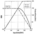
一方、上記説明した条件で、0〜255の多値データに対応した一様なパターンの明度L*を各色について測定した結果を図42に示した。
【0074】
ここでは、C,Mはほぼ同じカーブとなっている。
【0075】
そして、CのInputDataに対応している明度と一致するBkのInputDataをOutputDataとして表現した補完カーブを図37に、理想的な明度補完カーブとして示した。
【0076】
図37に示すグラフから、連続不吐の数が増大すると、補完カーブは理想的な明度補完カーブに近づいていることがわかる。
【0077】
逆にいえば、連続不吐の数が少なくなると、補完カーブは小さくなっていく。
【0078】
この理由は以下に説明する。
【0079】
すなわち、欠落部分に対して付与する、むらが見えなくなるような単位面積当たりの補完ドット数はほぼ一定と考えられるが、不吐数が少なくなるほど、1画素に対する欠落の割合が小さくなるため、その結果、補完ドット数は少なくなり、補完カーブが小さくなると考えられるのである。
【0080】
すなわち、図39に示すように、1不吐があった場合の欠落幅dは、インクジェットで印字したドットが、ほぼ円形のドットとなるため、1画素の幅より狭くなる。
【0081】
例えば、ここで説明している1200dpiの例では、1画素の幅は約21μmであるが、実際の欠落幅dは約15μmである。
【0082】
同様に、2,3,10ノズル連続不吐の場合の欠落幅を測定したところ、順番に35μm、約60μm、約200μmであった。
【0083】
この関係を図37に付記した。
【0084】
すなわち、実質的な欠落幅dは、不吐ノズルの数には比例しない。
【0085】
そこで、実質的な欠落幅dを考えるため、図40から斜線で示す欠落面積を計算した。
【0086】
そして、その値を1画素の面積で割ることで、不吐面積率を出した。
【0087】
連続不吐数に対応した不吐面積率を図43に示した。
【0088】
不吐数が増大すれば、不吐面積率は1に収束する。
【0089】
ここで、図37のInputDataが255(max)のときの補完ドットのOutputDataを欠落幅dに対応してグラフ化したものを図38に示した。
【0090】
一方、上記、不吐面積率に対応したInputDataが255(max)のときの補完ドットのOutputDataの関係を図41に示した。
【0091】
図41に示すグラフから、不吐面積率と、InputDataが255(max)のときの補完ドットのOutputDataはほぼ、比例していることが分る。
【0092】
ここで、不吐面積率とは、1画素に対する欠落の割合のことである。この1画素に対する欠落の割合は、図43から明らかなように、連続する不吐ノズルの数が少なくなるほど、小さくなるため、補完ドットのOutputDataが小さくなるのである。
【0093】
上述した結果から逆に考えると、連続不吐数やドット径等のドットのプロファイルから1画素に対する欠落割合が計算できるため、補完カーブは計算できる。
【0094】
すなわち、理想的な明度補完カーブに対して、1画素に対する欠落割合を乗じれば良いのである。
【0095】
一方、上記した、図35(a)のようなパターンを本体で検査パターンとして印字し、例えば、本体に搭載されたスキャナやセンサ等で読み取って図35(b)や図36のように判断を下してもいい。この場合、センサ等はデフォーカス等することで、実際に目で見る距離に相当した感度に設定し、1マスの中で、明らかに「白すじ」として検知するものと、明らかに「黒すじ」として検知できるものを除いたマス目の集合の中の中間部分を選択する等が考えられ、そのようにすることで図36のような補正カーブを得ても良い。
【0096】
以上、補正方法の例について、詳細に説明したが、マゼンタ(M)の不吐部分をBkで補完する場合もCと同様になる。
【0097】
以上の方法で、レッド(R),グリーン(G),ブルー(B)等の2次色に対する補完を行う場合について説明する。
【0098】
例えば、Rの場合、MとYの混合であるため、Mの一部が不吐した場合、不吐部分はYのデータはそのまま印字され、Mの不吐した分をBkで補完することが可能であり、その方が処理が容易である。
【0099】
すなわち、Mだけが印字された場合にそれを目立たなくするように設定した補完BkデータをYデータと混合して印字するのである。この場合、MとYの混合パターンの明度とMの補完ドットとしてのBkとYの混合パターンの明度は一致はしないが、明度差は±10%以内となり十分問題ない範囲となる。
【0100】
上述したように、不吐になって白すじとなった部分に、元の色の明度に近い色を補完することで、明視距離に対する不吐出の幅が十分狭ければ、「すじむら」として認識されにくくなることが分った。
【0101】
本検討によれば、補完する色を元の色の明度±20%にすることで、少なくとも補完しない場合に比べ、むらは良くなり、(逆に黒すじ等の悪くなることはない)好ましくは元の色の明度±10%以内の色にすることで、劇的に良くなることが分った。
【0102】
ドット数に関しては、図34(a),(b)に示すaの部分を構成しているドットに比べ、bの部分に補完するBkドットそのものの明度は低いため、補完するべきbの部分のBkドットのドット数は、印字されるはずであったドットに対して少なくなる。
【0103】
補完するドット数は、bの部分の明度をaの部分の明度±20%以内にしても、補完されるドット数を超えることはない。
【0104】
このときの、補完するドットの単位面積当たりの数の関係は以下の通りである。
【0105】
被補完ドットの数をLCとし、補完ドットの数をCとし、被補完ドットの画像データに対応したパターンでの明度に一致した補完ドットのパターンでの数をMとし、被補完ドットの画像データに対応したパターンでの明度+20%に一致した補完ドットのパターンでの数をMPPとし、被補完ドットの画像データに対応したパターンでの明度+10%に一致した補完ドットのパターンでの数をMPとし、被補完ドットの画像データに対応したパターンでの明度−20%に一致した補完ドットのパターンでの数をMMMとし、被補完ドットの画像データに対応したパターンでの明度−10%に一致した補完ドットのパターンでの数をMMとしたとき、
C<LC (式1)
M<LC (式2)
MPP<C<MMM (式3−1)
を満たすようなCとするのが好ましい。
更に好ましくは、(式1)と(式2)と、更に
MP<C<MM (式3−2)
を満足するCとするのが良い。
【0106】
このような補完方法は、例えば、シアンやマゼンタの被補完ドットに対してのBk補完ドットであり、淡シアンドットに対するシアンドットである。
【0107】
また、上記の例は、黒色で補完記録を行う例を挙げたが、他の色についても同様のことが言える。
【0108】
<Bkインクを用いた明度補完の実施例>
次に、不吐したノズルに代ってBkのドットで補完する手法について説明する。
【0109】
この手法は、補完するためのドットを、そのドットが出力データに基づき一様に印字された場合の明度が、不吐ノズル部の出力データによって一様に印字された場合の明度に対してある一定の明度差内になるような画像データに基づいて記録することを特徴とする。
【0110】
補完する色に関しては、当然ではあるが色度が近い色で補完することが好ましい。例えばシアンインク用のヘッドの不吐ノズルを補完する場合においては、マゼンタやブラックのインクを用いて明度を合わせるようにして補完を行うことが可能である。然しながら色度の観点からすれば、シアンとマゼンタの色度の違いによりその境界部分が比較的目立ちやすいため、Bkで補完する方がより好ましいものとなる。具体的には、本来Cのノズルで出力するべきデータの明度に対してある一定の明度差内になるような明度となるBkのデータに変換し、この変換したBkデータと本来のBkのデータを加算して出力するものである。
【0111】
例えば、このCからBkへの変換の一例は次のようにして行われる。
【0112】
図5は、各色のインクを普通紙に階調記録を行った場合の明度を表すグラフであり、横軸は各色に対応する入力値、縦軸は明度を表現している。ここで、シアン(C)のデータが「192」であった場合、その明度L*は約56となっている。一方、Bkにおいて明度が約56となるのは入力値が約56のときである。
【0113】
このことから、シアンの不吐出のノズルに対応するデータが「192」のとき、このデータを、ブラックインク用のデータ「56」に変換する。
【0114】
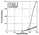
このようにして求めたC,Mと補完するBkとの関係を図6に示す。図6は、不吐出のノズルに対応する入力データに対し、変換後の補完記録のための出力データを表すグラフである。図中、#C_Bkは、シアンに対しブラックインクを用いて補完する場合の関係を示し、#M_Bkは、マゼンタに対しブラックインクを用いて補完する場合の関係を示す。シアンやマゼンタの不吐出による欠落部分をブラックインクにより補完する場合は、図6に示すような変換を行うためのテーブルを用い、欠落部分に対応したデータを変換して得られたBkのデータを、本来のBkのデータに加算して出力することで、不吐の影響を減ずることができる。なお、Y(イエロー)に関しては、本来、明度が紙面に対して余り変化しない。即ち、目につきにくいことから特に異なる色で補うことはしなくとも良い。
【0115】
なお、図6において、#Bk_cmyは、ブラックの欠落部分を、C,M,Yの3色により補完する例を示しており、Bkの不吐に対しては、C,M,Yを用いて、補うことも可能である。また図5,図6の関係は当然使用する媒体、インク、吐出するインク量等により異なるため、使用するシステムにおいて、変換テーブルを各種用意することが必要である。
【0116】
<ヘッドシェーディングによる補完>
次に、ヘッドシェーディングの処理により欠落部分を目立ちにくくする手法について説明する。ここで、ヘッドシェーディングとは、記録ヘッドに設けられる複数のノズルそれぞれの吐出特性のばらつきが主な原因となって発生する濃度むらを補正するために用いられる技術であり、濃度を均一化させるための補正データを個々のノズルに対応させて設定することにより、濃度むらを目立ちにくくするものである。具体的には、記録ヘッドにより試験的に記録した画像の濃度をスキャナで読み取り、濃度が低い部分に対応したノズルに対して濃度を高めるための補正データを設定し、逆に濃度が高い部分に対応したノズルに対して濃度を下げるための補正データを設定することで、濃度の均一化を図る。
【0117】
この、ヘッドシェーディングの処理を行うことにより、元画像の不吐の部分(欠落部分)に対応した領域に対して、少なくとも前記領域に隣接する画素周辺の印字dutyを高くするように補正され、不吐の部分を目立ちにくくすることができる。
【0118】
即ち、具体的には、別記するように、ヘッドシェーディングは、記録ヘッドにより記録したテストパターンの濃度を読み取り、その濃度のむらに応じて各ノズル毎の出力γを変更することにより「むら」を取り除くものであるが、読み取った濃度むらのデータは、通常別記するように400dpi〜600dpiの解像度の出力では注目ノズルとその両隣りのノズル部の濃度の平均値を取ることによって、注目ノズルにおける濃度と見做し、補正を行っている。
【0119】
従って、不吐出が発生したノズルがあると、その両隣りのノズル部に対応する濃度も結果として低下するため、ヘッドシェーディングの処理により、不吐出が発生したノズルの両端のノズル部における印字データは、濃度を高くするよう補正される。
【0120】
その結果、不吐ノズルに対応する画素の近傍は、その両隣りも含めると印字ドット数が不吐がない場合と比べて同等になるため、むらとして認識できなくなる。
【0121】
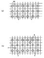
図4(a)〜(e)に、ヘッドシェーディングにより不吐出のノズルに隣接するノズルの画像データが補正される状態を模式的に示す。
【0122】
図4(a)〜(d)は、100%のデューティでドットが記録される場合、各格子内に4つのドットが記録される例を示すものである。また、図4(e)は、100%のデューティでドットが記録される場合、一つの格子内に2つのドットが記録される例を示している。また、図の縦方向にノズルが配列された記録ヘッドにより記録される画像であり、図中のAで示す箇所が、不吐出のノズルによって記録が行われない位置を示している。
【0123】
図4(a)は、1/4のデューティで記録される画像を示しており、前述したヘッドシェーディングの処理により、不吐出ノズルに隣接するノズルのデータが濃度を高くするように補正され、結果として記録されるドット数が増える。また、図4(e)は、1/8のデューティで記録される画像を示している。このようにデューティが低い場合においては、不吐出ノズルによって発生する「すじ」は目立ちにくく、隣接するノズルにより記録されるドットが増えることで、見た目の濃度についても、正常な記録ヘッドで記録した場合と比較して、大きな差は生じない。
【0124】
図4(b)は1/2のデューティ(50%)で記録される画像を示しており、また図4(c)は3/4のデューティ(75%)で記録される画像を示している。この図4(c)の例では、デューティが高く、不吐出ノズルの隣接するノズルのみでは、不吐出ノズルに対応する画像の濃度を再現できないため、不吐出ノズルから2ノズル目の位置のノズルに対しても、濃度を高くする補正を行っている。この図4(b),(c)で示すように、記録されるドットの密度が高くなるにしたがって、不吐出ノズルに対応した位置(図中矢印Aで示す位置)の欠落部分が「すじ」となって目立ちやすくなる。
【0125】
従って、上述のヘッドシェーディングの処理は、デューティが低い画像領域について、特に効果的に不吐出による画像の欠落で生じる濃度低下を抑えることができる。
【0126】
図4(f)は、上記ヘッドシェーディング等により不吐出と判定されたノズルに隣接するノズル部におけるγ補正の例を示す。図中、4aは、補正なしの傾きを示している。4bは、元の画像データに対して、γ補正により1.5倍に濃度を高める補正の例を示す。このように、不吐出ノズルに隣接するノズルに対して、濃度を最大で1.5倍とするγ補正を行ってもよい。
【0127】
また、図4(f)において、4cは、他の色により補完記録を行う例において説明するものであり、この例は後述する。
【0128】
上述したように、ヘッドシェーディングの処理により、一様な印字パターンの場合、低印字dutyであれば、不吐出ノズル近傍の印字ドット数はその周囲と比べてもほぼ同じとなり、「むら」として認識しにくいものとなる。
【0129】
<明度補完とヘッドシェーディングの組合せ>
前述した不吐の部分を他の色を使用して補う方法と、不吐の部分の両側のノズルを使用して補う方法の二つを組み合わせて使用することも可能である。
【0130】
次に、前述した明度を合わせて他の色で補完する手法と、前述したヘッドシェーディングの手法とを組み合わせることにより、不吐出ノズルによる画像の欠落を更に効果的に目立たなくする構成について説明する。
【0131】
なお、この際には、各種補正量を適宜修正し、最適化して使用することが好ましい。低印字dutyの領域ではヘッドシェーディングにより、不吐ノズルに対応する画素の近傍は、その両隣りも含めると印字されるドット数が、不吐がない場合と比べて同等になるため、前述と同様むらとして認識できなくなる(図4(a)〜(e)参照)。
【0132】
しかし、前述のヘッドシェーディングの手法では、ベタ画像のような高印字dutyの画像の場合、不吐出のノズルに対応した部分が白すじとなって目立ちやすいため、「すじ状のむら」として認識される。よって、低印字duty時はヘッドシェーディングにより補正し、高印字duty時は、さらに他の色のドットにより補完することにより、画像の印字デューティの違いによらず、不吐出ノズルによる画像の劣化を抑えることができる。
【0133】
図4(f)は、ヘッドシェーディングの処理と、他の色による補完の処理とを組み合わせた例を示している。例えば、不吐出ノズルに隣接するノズルについては、図中の4bで示す直線に従った補正を行うとともに、デューティが高い場合には、他の色により、不吐出のノズルに対応した部分を補完する。補正直線4bは、画像濃度を1.5倍にするγ補正を示している。また、デューティが2/3(67%)を越える画像データについては、図中の点線4cで示す画像データを、他の色に対応させて発生させる。このような処理を行うことにより、デューティが2/3より低い場合は、隣接するノズルに対応した位置の画像濃度を高めることにより、不吐出による欠落部分を目立ちにくくするとともに、デューティが2/3より高い場合は、不吐出による欠落部分に対して、他の色により、明度を合わせるように補完記録を行うことができる。
【0134】
以下、上述した本発明の補完の手法を基に、インクジェット方式の記録装置を例に挙げて詳細に説明する。
【0135】
なお、本発明においては、スキャナ機能を持ったプリンタ、または、濃度むら及び不吐ノズル測定用パターンを読み取ったデータが入力可能なプリンタであれば実施可能であるが、ここでは、カラー画像の読み取りと記録とが可能なインクジェット方式のカラー複写機を例として説明する。
【0136】
(第1の実施例)
<明度補完とBk補完との組合せによる手法>
本実施例は、不吐ノズルに対して異なる色、特にシアン(C),マゼンタ(M)に対して、ブラック(Bk)のインクを用い、不吐ノズルに対応する画像データに基づいて、明度を合わせるよう補完するものである。
【0137】
以下、図面を参照して本発明の好適な実施例を詳細に説明する。
【0138】
図13は本実施例のインクジェット記録装置を使用したカラー複写機の構成を示す側断面図である。
【0139】
このカラー複写機は、画像読取りおよび画像処理部(以下、リーダ部24と称す)とプリンタ部44とで構成されている。リーダ部24はR,G,Bの3色のフィルタを有するCCDラインセンサ5により、原稿ガラス1上に載置された原稿2をスキャンしながら画像を読取り、当該読取り画像を画像処理回路で処理して、プリンタ部44にてシアン(C),マゼンタ(M),イエロー(Y),ブラック(Bk)の4色のインクジェットヘッドにより紙その他の記録媒体(以下記録紙ともいう)に画像の記録を行っている。
【0140】
尚、画像データを外部から入力し、このデータを画像処理回路で処理してプリンタ部44にて記録することも可能である。
【0141】
以下、装置の動作を詳細に説明する。
【0142】
リーダ部24は部材または部分1〜23からなり、プリンタ部44は部材または部分25〜43から成る。また、図13において、図の左上側が操作者が対面する前面となっている。
【0143】
プリンタ部44は、インクを吐出することにより記録を行うインクジェットヘッド(以下、記録ヘッドともいう)32を備えている。また、この記録ヘッド32は、例えば、インクを吐出するためのノズルが128本配列されており、ノズルの吐出方向側には吐出口が形成されている。ここでは、63.5ミクロンのピッチで128個の吐出口が、所定の方向(後述する副走査方向)並置されており、8.128ミリメートルの幅を記録することができる構成になっている。従って、記録紙に記録する場合は、一旦記録紙の搬送(副走査方向の搬送)を止め、この状態で記録ヘッド32を図面に垂直な方向に移動させて8.128ミリメートルの幅で必要距離だけ記録した後、次に記録紙を8.128ミリメートルだけ送って止め、次の8.128ミリメートルの幅の画像を記録するという動作を繰り返すことになる。この記録方向を主走査方向、紙送り方向を副走査方向と呼ぶ。本実施例の構成では、主走査方向は図13に対し垂直な方向、副走査方向は図13における左右方向である。
【0144】
またリーダ部24は、プリンタ部44に対応して原稿2を8.128ミリメートルの幅で読取る動作を繰り返すが、読取り方向を主走査方向、次の読取りのために移動する方向を副走査方向と呼ぶ。本実施例の構成では、主走査方向は図13の左右方向とし、副走査は図13に対し垂直な方向とする。
【0145】
リーダ部24の動作を説明すると以下のようである。
【0146】
原稿台ガラス1上の原稿2は、主走査キャリッジ7上のランプ3により照射され、その画像はレンズアレイ4を通して受光素子5(CCDラインセンサ)に導かれる。主走査キャリッジ7は副走査ユニット9上の主走査レール8に嵌合し、スライド可能になっている。さらに、主走査キャリッジ7は図示していない係合部材で、主走査ベルト17と連結しており、主走査モータ16の回転によって、図13上で左右方向に移動し、主走査動作を行う。
【0147】
副走査ユニット9は光学枠10に固定された副走査レール11に嵌合していてスライド可能になっている。さらに、副走査ユニット9は図示していない係合部材で副走査ベルト18と連結しているので、副走査モータ19の回転により図13上で垂直方向に移動し、副走査動作を行う。
【0148】
こうして、CCDラインセンサ5により読取られた画像信号はループ状に湾曲可能なフレキシブルな信号ケーブル13によって副走査ユニット9に伝えられる。信号ケーブル13は主走査キャリッジ7上で、その一端が挟持部14に挟持され(くわえられ)ており、他端は、副走査ユニットの底面20に部材21によって固定されて、副走査ユニット9とプリンタ部44の電装ユニット26とを結ぶ副走査信号ケーブル23に結合されている。ここで、信号ケーブル13は主走査キャリッジ9の動きに追従し、副走査信号ケーブル23は副走査ユニット9の動きに追従している。
【0149】
図14は本実施例のCCDラインセンサ5の詳細を示す図である。このラインセンサ5は498個の受光セルをライン状に備え、R,G,Bの3画素で1画素を構成しているため、実質的に166画素を読取ることができる。このうち有効な画素数は144画素で、この画素数からなる画素幅はほぼ9mmである。
【0150】
次に、プリンタ部44の動作を説明すると以下のようである。
【0151】
図13において、記録紙カセット25から図示されない動力源によって駆動された給紙ローラ27によって1枚づつ送り出された記録紙は、二組の対となるローラ28,29及び30,31の間で記録ヘッド32によって記録される。記録ヘッド32はインクタンク33と一体に構成され、プリンタ主走査キャリッジ34上に着脱可能に載置されている。プリンタ主走査キャリッジ34は、プリンタ主走査レール35に嵌合していてスライド可能になっている。
【0152】
更に、プリンタ主走査キャリッジ34は図示していない係合部材で主走査ベルト36と連結しているので、主走査モータ37の回転によって、図13に対して垂直方向に移動して主走査動作を行う。
【0153】
プリンタ主走査キャリッジ34には、アーム部38があり、記録ヘッド32に信号を伝えるプリンタ信号ケーブル39が固定されている。プリンタ信号ケーブル39の他端は、プリンタ中板40に部材41によって固定され、更に電装ユニット26に結合されている。このプリンタ信号ケーブル39は、プリンタ主走査キャリッジ34の動きに追従し、なお且つ上部の光学枠10に接することが無いように構成されている。
【0154】
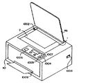
プリンタ部44の副走査は、二組の対となるローラ28,29および30,31を図示しない動力源によって回転させ、記録紙を8.128mmづつ搬送することによって行う。42はプリンタ部44の底板、45は外装板、46は原稿を原稿台ガラス1に圧着するための圧着板、1009は排紙口(図26参照)、47は排紙トレーそして48は操作面の電装部である。
【0155】
図15は本実施例のカラー複写機のプリンタ部44におけるインクジェットカートリッジの外観を示す斜視図である。また図16は図15のプリント基板85の詳細を示す斜視図である。
【0156】
図16において、85はプリント基板、852はアルミ放熱板、853は発熱素子とダイオードマトリクスからなるヒータボード、854は個々のノズル情報を、予め記憶している記憶手段であってEEPROM等の不揮発性メモリその他適宜の形態を可とする。
【0157】
本実施例においては、不吐ノズルか否かの情報を記憶してあるが、他に濃度むら等の情報も記憶することが可能である。
【0158】
855は本体とのジョイント部となる接点電極である。なお、ここではライン状に配列された吐出口群は図示されていない。
【0159】
こうすることにより、本体装置に記録ヘッド32が装着されると、本体装置は記録ヘッド32から不吐ノズルに関する情報を読み出し、この情報に基づいて濃度むら改善のための所定の制御を行う。これにより、良質な画像品位を確保することが可能となる。
【0160】
図17(a)および(b)は図16のプリント基板85上の要部回路構成例を示す図である。ここで、図17(a)に示す一点鎖線の枠内がヒータボード853内の回路構成であり、このヒータボード853は発熱素子857と電流の回り込み防止用のダイオード856とを直列接続した回路のN×Mのマトリクス構造で構成されている。即ち、これらの発熱素子857は、図18に示すように各ブロック毎に時分割で駆動され、その駆動エネルギーの供給量の制御はセグメント(Seg)側に印加されるパルス幅(T)を変更して制御することにより実現される。
【0161】
図17(b)は図16のEEPROM854の一例を示す図であり、本実施例においては、不吐ノズルに関する情報が記憶されている。この不吐ノズル情報は、本体装置側からの要求信号(アドレス信号)D1に応じてシリアル通信により本体装置側の画像処理部へ出力される。
【0162】
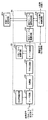
本実施例における画像処理部の構成例を図21に示す。
【0163】
図21において、固体撮像素子の一つであるCCDセンサ5から読み込まれた画像信号は、シェーディング補正回路91でそのセンサ感度が補正され、色変換回路92で光の3原色R(レッド),G(グリーン),B(ブルー)から印刷色であるC(シアン),M(マゼンタ),Y(イエロー),Bk(ブラック)へと変換される。
【0164】
この変換は通常3次元LUT(ルックアップテーブル)を利用して行われるが、特にこの方法に限られるものではない。また、印刷色がC,M,Y,Bkだけでなく、濃度の低いLC(ライトシアン),LM(ライトマゼンタ)等を含む場合においても適応可能である。
【0165】
また、画像データとして、外部から直接色変換回路92へ入力し、処理することも可能である。
【0166】
これらのRGBから変換されたC,M,Y,Bk信号はデータ変換部94に入力される。データ変換部94では、インクジェット記録ヘッドに備えてある記憶手段854の不吐ノズル情報、若しくは別途不吐ノズル測定を経て算出された不吐ノズル情報を使用して、後述するようにデータ変換され、γ変換回路95に供給される。なおここで使用したノズル毎の特性は、データ変換部94の中のメモリに蓄積されている。
【0167】
γ変換回路95は、例えば図22に示すように、入力データに対する出力データを算出するための数段階の関数を有しており、色毎の濃度バランスや使用者の色合いの好みに応じて適切な関係が選択される。またこの関数はインク特性や記録紙に応じて決定される。なお、このγ変換回路95は、色変換回路92に取り込んでしまうことも可能である。この出力は2値化回路に送られる。
【0168】
本実施例においては誤差拡散法(ED)を採用した。
【0169】
2値化処理回路96の出力はプリンタ部44に送られ、記録ヘッド32により記録される。
【0170】
なお、本実施例においては、2値化処理回路を使用し画像を出力しているが、本発明は、この2値化処理回路に限られるものではない。例えば大小ドットを利用した3値化であっても良いし、1画素中に0〜n発のドットを記録することによるn+1値化処理回路であっても良い。種々の出力方法に応じて適宜選択すれば良い。
【0171】
以下、本発明の最も重要な動作であるデータ処理部100を構成する不吐ノズル/濃度むら測定部93とデータ変換部94について説明する。
【0172】
図23は、図21におけるデータ処理部100の機能を示す要部構成例ブロック図であり、破線で囲んだ部分が、夫々、不吐ノズル/濃度むら測定部93とデータ変換部94である。
【0173】
初めに、不吐ノズル/濃度むら測定部93の具体的な動作について説明する。
【0174】
この処理は、不吐ノズルに関する情報の更新の必要があれば、不吐/むら読取りパターンの印字と、同パターンの読取り及びデータ演算とから成り、また、不吐ノズル情報の更新の必要がなければ、省略することができる。
【0175】
尚、本実施例においては、濃度むらに関する補正処理は行わないが、この不吐ノズル/濃度むら測定部93では、濃度むらに関する情報も取得可能であり、且つ他の実施例で使用するので、その説明も付け加えることとする。
【0176】
不吐ノズルに関する情報を更新する場合、最初に不吐/むら読取りパターンの印字が行われるが、それに先立ち、まずヘッドの回復動作が行われる。これは記録ヘッド32の固着インクの除去、ノズルからインクを吸引することによる気泡の除去とヘッドヒータの冷却などを一連の動作で行い、むら読取り用パターン印字を最善の状態で行わしめるための準備動作として強く望ましいものである。
【0177】
次に図27に示すむら読取り用パターンを印字出力する。印字パターンは濃度50%のハーフトーンを各色4ブロックづつ、同図の縦方向に印字し、計16ブロックのパターンからなっている。パターンは記録用紙の定められた位置に印字される。また各ブロックは3ラインの印字から作られ、1,3ライン目は128ノズルのうちのそれぞれ下端部、上端部の16ノズルからだけ吐出を行わせ、2ライン目は128ノズル全てから吐出を行わせることによって計160ノズル分の印字幅を持ったハーフトーンの印字ブロックとなる。ここで各ブロックを160吐出口分の幅で記録する理由は次の通りである。
【0178】
図28に示すように、例えば128個のノズルからなる記録ヘッド32を用いた場合には、この記録ヘッド32により記録されたパターンをCCDセンサ5などで読取ると、記録紙の地色(例えば白)の影響により濃度データAnがだれる傾向を示す。従って、もし各ブロックを128吐出口でしか記録しなければ、端部吐出口の濃度データの信頼性がなくなる虞れがある。そこで、本実施例では160吐出口で印字し、ある閾値以上の濃度データを有効データとして扱い、有効データの中心を中心吐出口と見做し、その点から(吐出口数)/2(この場合64)づつ隔てた点のデータを、それぞれ第1吐出口,第128吐出口に対応させた。
【0179】
なお、両端パターンを印字するノズル数は、特に16ノズルに限定されるものではない。本実施例においては、データ保存メモリの節約を目的とし、16ノズルと決定した。
【0180】
読取りパターンの印字が終了した後、出力された記録用紙2を図26の原稿台1にパターンを下向きにし、かつ同色の4ブロックがCCDセンサ5の主走査方向に並ぶように置き、むらパターンの読取りを開始する。
【0181】
不吐/むら読取りに先立ち、まず図26の基準白色板1002を用いてCCDセンサ5のシェーディング処理が行われ、続いてむら読取りパターンの読取りが行われる。ここでいう1ラインは或る色の4ブロックを1度に読取るCCDセンサの1主走査を指している。従って、1ライン読取りで、ブラックのパターンが4ブロック分メモリ(SRAM)に格納される。4ブロックそれぞれの読取られたデータ(濃度データ)はメモリの或る定められたエリアに納まるように、記録紙上の定められた位置に印字されている。この読取ったデータの形は、普通は図29(a)のようになっている。ここで横軸がSRAMのアドレス、縦軸が濃度を表す。先にも述べたように或る決まった濃度レベル以上の範囲を印字領域とするわけであるが、ここではスレッショルドを初めて超えた濃度のアドレスX1がある許容範囲の中に入っているかを確認する。SRAMの読みはじめから印字開始位置がXで始まっていたとするとき、X1がX±Δxの中にあるのかどうかを、さらにはX1+160±Δxの位置でデータがスレッショルド以下に落ちているかをチェックする。
【0182】
これが満たされない場合、斜め置きの可能性があるためエラーと判断し、やり直すか、もしくはデータ回転処理を行った後、再びチェックするようにする。このようにして、データとノズルの1対1の対応を行う。不吐ノズル検知は印字領域と判断されたX1からX2までの範囲の濃度データを一画素づつ取出し不吐ノズル用のスレッショルド以下になっていないかをチェックする。
【0183】
一般に図29(c)に示すように1ノズルのみが不吐出であったとき、その領域は白紙領域と同じ程度の濃度には下がらない。そこで本実施例では不吐ノズル検知用のスレッショルドを別に設け、印字領域内のデータがこれより低い場合に不吐出があると判断している。
【0184】
ところで、ヘッド自体の状態が不安定の場合、吐出口が突発的に不吐出になってしまうこともある。
【0185】
例えば、図27の4つの印字パターンのうち4つとも不吐出がある場合、これは完全な不吐出であるが、もし1つの領域以外には不吐出がなかった場合、不吐出がある部分は突発的なものと判断して、残りの部分のみ使用して計算を行うことにしても良いし、エラーとして再度印字から始めても良い。なお、不吐出のスレッショルドは特別に設けることなく、先に述べた印字領域用スレッショルドを少し高い位置に設けて、同時に検知することが可能である。
【0186】
さて、これらデータは、不吐/むら演算回路135(図23)へと入力される。
【0187】
本実施例における演算は、不吐ノズル決定処理であるが、むら補正の為の濃度比率決定処理についても併せて示す。
【0188】
ここで、図29(c)のような形でデータが実際に入力されたところから、図30を参照して順次説明していく。まず両端の立ち上がり位置X1,X2の平均を取り、印字領域の中心値を求める。ここを、ノズル列の中心部、即ち64番目と65番目のノズルの間であると判断する。従ってその中心部から64画素づつ前後した位置にあるデータが1番ノズルと128番ノズルの濃度ということになる。これにより両端のつなぎ部分も含めた印字濃度n(i)が各ノズルで得られたことになる。ここで各ノズルに対する印字濃度n(i)が不吐ノズル検知用のスレッショルドよりも小さい場合には、そのノズルを不吐ノズルと確定し、そのノズルの濃度比率情報をd(i)=0と設定する。また、本実施例では、以下に示す濃度比の演算は行わない為に、その他のノズルの濃度比率情報をd(i)=1と設定している。
【0189】
濃度比率情報の設定は、以下に示すように行うことができる。
【0190】
不吐ノズルを除いた全ノズルの平均濃度AVEを求め、その平均濃度に対する各ノズルの濃度比率d(i)=n(i)/AVEを各ノズルの濃度比率情報とするものである。
【0191】
しかし、この1画素分の幅しか持たない領域の濃度データをそのままノズルの濃度データとして用いてしまうのは好ましくない。何故なら、図31で示すように、読取り領域の1画素分には、両側のノズルから吐出されたドットによる濃度も含まれていることは確実であるし、どのノズルにおいても多少は左右どちらかによれていることは免れないからである。さらに、人間の目に映る濃度むらが注目画素を含む周囲の状況に応じて影響されることも加味するのが望ましい。
【0192】
従って実用的には各ノズルの濃度を決定する前に、図32に示すようにその画素と両側の画素を含めた3画素程度の濃度データ(Ai−1,Ai,Ai+1)の平均値を順次求めて、これをノズル濃度ave(i)とし、この値を用いて各ノズルの濃度比率情報d(i)=ave(i)/AVEとすることが好ましい。この濃度比率情報を用いて、後述する補正テーブルの作成が行われることになる。
【0193】
この濃度比率情報d(i)は、補正テーブル演算回路136(図23参照)において処理され、各ノズルに対する補正テーブルが設定される。
【0194】
この決定式のテーブル番号をT(i)とすると、
T(i)=#63 :1.31<d(i)
#(d(i)−1)×100+32 :0.69≦d(i)≦1.31
#1 :0<d(i)<0.69
#0 :d(i)=0
である。ここでは、図24に示す様に64本の補正テーブル#0〜#63が用意してあり、テーブルナンバ#32を中心に少しづつ傾きを増加/減少させてある。
【0195】
テーブルナンバ#32は入力値と出力値が常に等しい傾き1の直線になっている。これが128個の吐出口の平均濃度を出す吐出口の取るべきテーブルである。その上下にふられた残りの曲線は、印字サンプルと等しい濃度50%(80H)のところで#32を中心に1%刻みでテーブルが存在するようになっている。従って上式で求められたT(i)は常に80Hの入力信号において濃度比率に一致した信号値変換が行われるわけである。また、#0は不吐ノズルに対応しており、その出力は全て0に設定してある。
【0196】
このようにしてT(i)を128個求めたところで1ライン補正テーブル番号算出は終了する。
【0197】
尚、本実施例においては、濃度比率決定処理は行っていない為、全てのノズルに対して#0または#32が算出されている。
【0198】
以上で1ラインすなわち1色分の不吐ノズルおよびむら読取りと、そのデータから補正を行った各ノズル毎の補正テーブル番号の算出が完了し、これを4ライン分すなわち4色のヘッドに対して同様な処理を行う。4色分の補正テーブル番号が算出されたら、次に補正テーブル番号保持部137の更新を行う。この中には記憶手段である記録ヘッド記憶情報854から読み込まれた補正テーブル番号が格納されており、ここで算出された最新の補正テーブル番号が、この補正テーブル番号保持部137及び記録ヘッド記憶情報854の内容に書き換えられる。
【0199】
即ち、不吐/むら検出を行わなかった場合には、記録ヘッド記憶情報854に保持されていた補正テーブル番号が以下の処理に利用されることとなる。
【0200】
データ変換演算回路138においては、出力する画像信号を前述した各ノズル毎の補正テーブルを使用して出力し、ヘッド毎の信号へと変換する。この処理のフローを図9に示す。
【0201】
データ変換部94に入力したC,M,Y,Kの画像信号は、実際に記録を行うノズルと対応づけられる(S2001)。さらに記録を行う際に同一画素となる各色のデータが選択され、一括して処理されることとなる。
【0202】
ここで、各ノズル毎の濃度補正テーブルが参照され(S2002)、データが変換される。このデータ変換については、補正テーブルが#1〜#63の場合と#0、すなわち不吐である場合との2つに大別される(S2003)。
【0203】
補正テーブルが#1〜#63の場合には、入力信号がそのまま色別データ加算部へ送られる(S2005)。
【0204】
一方、補正テーブルが#0の場合、即ちそのノズルが不吐の場合には、それを補う為の補完データが作成される(S2004)。例えば入力信号がCの場合には#C−K補正テーブル、入力信号がMの場合には#M−K補正テーブルを用いてBkデータを作成する。またその入力信号がYのときはBkデータは作成せず、さらにBkの場合には#Bk−cmyを用いて、C,M,Yそれぞれのデータを作成することとなる。
【0205】
この補完データは、本実施例においては、前述した様に明度がほぼ等しくなるように作成する。図5は入力値に対する各色の明度の出力値を示すグラフであり、このグラフを元に補完テーブルが作成してある。例えばシアン(C)のデータが「192」(8bit入力)である場合、その明度は約56となっている。
【0206】
一方、黒(Bk)において明度が約56となるのは8bit入力値がほぼ56であり(Bk=56)、この結果、C=192はBk=56に変換される。同様にして求めたマゼンタ(M)に対する黒(Bk)の補完テーブル(#M−K)も併せて図6に示す。
【0207】
一方、イエロー(Y)に対する補完は、このイエロー(Y)の明度が常に高いことを考慮し、特に行わないこととする。また、黒(Bk)に対する補完は、C,M,Y夫々を同じ割合で補完することとした。その結果得られた補完テーブルを#Bk−cmyとして図6に示す。
【0208】
これら補完テーブルを使用して補完データを作成することとなるが、実際には記録するドット径と画素ピッチの関係も考慮することが望ましい。例えば、本実施例においては、記録するドット径は約95μmであり、画素ピッチは63.5μmである。これは100%印字した時に多少の着弾ずれが生じても、エリアファクター100%が得られるように設定してあることによる。
【0209】
従って、例えば1ノズルのみ不吐の場合には、不吐ノズルに対する画素には、その両側の画素に記録したドットの影響がかなり及んでいることとなる。
【0210】
換言すれば、不吐ノズルの部分に記録する補完されたドットは、その両側の画素に少なからず影響を及ぼすということになる。
【0211】
これは、不吐ノズルが連続していなければ、補完するデータは明度との関係から求めた値よりも少なくてよいということと等価である。
【0212】
言い換えれば、不吐ノズルにより生じた欠落幅が実質的な補完すべき画素の面積を小さくしているわけであり、結果として、補完データは明度との関係から求めた値よりも少なくて良い。
【0213】
どの程度少なくするかは、図43に示すような連続不吐数に対する不吐面積率を補完データに乗じるのが好ましい。
【0214】
具体的には図6のC,Mに対するBkの補完カーブをf(x)(xはInputData)とした場合、図43のような連続不吐数に対する不吐面積率をαとし、新たなBkの補完カーブをα・f(x)とする。
【0215】
従って、本実施例においては、図7に示すような補完テーブルを使用した。
【0216】
尚、同様に、不吐ノズルが1個単独の場合、2個連続してある場合、3個連続してある場合、といった様に態様別に、夫々の態様に対して異なる補完テーブルを設定することが好ましい。その場合も、上記した図43に示した連続不吐数に対応した不吐面積率を補完データに乗じて新たな補完データとすることにより、より精密な明度を併せた補完を実施することが可能となる。
【0217】
ここで作成された補完データは、色毎にデータ加算部に送られる(S2005)。
【0218】
データ加算部では、色毎にデータを保持する機能と演算処理する機能を備えていて、このデータ加算部に入力されたデータが初めてであるときは、そのままデータが保持される。また、既にデータが保持されている場合には、そのデータが加算される。また加算されたデータが255(FFH)を超えた場合には、255として保持される。なお本実施例においては単純な加算処理を行っているが、必要に応じて、各種演算やテーブルを利用した処理を行っても良い。
【0219】
C,M,Y,Bk全ての色に対してデータの加算処理が行われた後、このデータはデータ補正部に渡され(S2006)、データ加算部のデータはリセットされ、次の画素の処理を待つこととなる。データ補正部に渡されたデータは、そのノズルの補正テーブル(#0〜#63)に従い変換され、一連のデータ変換の終了となる。
【0220】
この様にして変換されたデータは、γ変換回路95、2値化処理回路96等を経て、画像が出力されることとなる。
【0221】
この様にして得られた画像は、近づけて凝視すると、不吐の部分が認識できるが、全体としてほぼ良好なものであった。
【0222】
<ヘッドシェーディングによる処理の例>
ここで説明するのは、ヘッドシェーディング、所謂「濃度むら」補正の一連の動作のなかで、不吐ノズルの補正を行うものである。以下具体的に説明する。
【0223】
本例も、前述の実施例と同様のシステムで行われ、異なる点は、むら補正を行うことと、異なる色による補完データを作成しないことである。
【0224】
この2点を中心に、以下データ変換処理、即ち、不吐ノズル/濃度むら測定部93とデータ変換部94の処理について説明する。
【0225】
図21において、不吐ノズル/濃度むら測定部93での処理は、基本的に前述の実施例の場合と同様である。図23のブロック図に示すように、初めに不吐/むら読取りパターンを印字し、次にCCDセンサを用いてこの画像データを読取り、加算、平均化等の処理を行って、図30に示すようなノズルと対応づけられた印字濃度n(i)を得ることができる。
【0226】
さて、本例の理解を容易にするため、まず最初に、濃度むら発生の基本的要因について説明する。
【0227】
図19(a)は、理想的な記録ヘッド32での記録状態を拡大して示した模式図である。図中、61はインクの吐出口を示し、この記録ヘッド32で記録した場合には均一なドロップ径(液滴径)でのインクスポット60が用紙上に整列して記録される。
【0228】
尚、同図では所謂全吐(全吐出口がONの状態)の場合を示したが、例えば、50%出力のようなハーフトーンの場合でも濃度むらは発生しない。
【0229】
それに対し、図19(b)に示したケースでは、2番目及び(n−2)番目の吐出口のドロップ62、63の径が他より小さく、また(n−2)番目と(n−1)番目については理想的着弾中心よりも、ずれた位置に記録されている。即ち、(n−2)番目のドロップ63は中心よりも右上方に、また(n−1)番目のドロップ64は中心よりも左下方に偏って記録されている。
【0230】
この様に記録された結果として、図19(b)に示したA領域は薄い筋となって現われ、またB領域も(n−1)番目と(n−2)番目の中心間距離がドロップ間の平均距離l0よりも大きくなるため、結果的に他の領域よりも薄い筋となって現われる。一方、C領域では、(n−1)番目とn番目の中心間距離が平均距離l0よりも狭くなるため、他の領域よりも濃い筋となって現われることになる。
【0231】
以上述べたように、濃度むらは主としてドロップ径のばらつきと中心位置からのずれ(これを一般に「よれ」と称する)に起因して現われるものである。
【0232】
この濃度むらに対処するための手段として或る領域内の画像濃度を検出し、その検出値に基づいて、その領域内へのインク打込み量を制御するという方法が有効である。
【0233】
例えば、図20(a)に示すように理想的な記録ヘッドによる50%のハーフトーン記録に対し、図20(b)に示すようなドロップ径の“ばらつき”や“よれ”のある記録ヘッドによる記録において、濃度むらが目立たないように実現するには次のようにする。即ち、1例として図20(b)に示す破線a内領域での合計ドット面積を、図20(a)の領域aの合計ドット面積に近づけることにより、図20(b)に示すような特性を有する記録ヘッドによる記録においても、肉眼では図20(a)と同等の濃度に感じられるようになる。
【0234】
また、図20(b)のb領域についても同様に行うことにより、濃度むらが実際上解消されることとなる。
【0235】
なお、図20(b)は、説明を簡略化するために、濃度補正制御の処理結果をモデル化して示したもので、αとβは補正用のドットを示している。
【0236】
また、不吐ノズルに対しては、吐出されたドロップ径が限りなく「0」に近づいたものとして捉えることにより、このシステムを適用することが可能となる。
【0237】
この観点から、各ノズルに対応した濃度比率データは前述の実施例の中で示したように、
【0238】
【表1】

とすることが重要となる。即ち、i0のノズルが不吐の場合、n(i0)=d(i0)=0と設定する。その為、不吐ノズルの両側のノズルi0+1、i0−1においては、そのノズルの実効濃度ave(i0+1)、ave(i0−1)は、n(i0+1)、n(i0−1)に比べて大幅に小さな値となる。その結果、濃度比率情報d(i0+1)、d(i0−1)が実質小さくなり、後述する補正テーブルにより、より高い濃度を出力するように設定され、不吐ノズルを補う役割を果すこととなる。従って、ノズル毎の実効濃度ave(i)を算出する計算式は、前に示した前後3画素の平均値だけに限られるものではなく、例えば、ave(i)=(2n(i−1)+2n(i+1)/5というように適当な加重をかけた平均値を用いても良く、適宜選択することが可能である。
【0240】
この様に求められた濃度比率情報d(i)は、データ変換部94中の補正テーブル演算回路136にて処理され、各ノズルに対する補正テーブルが設定される。この処理は、前述の実施例で示したものと同じであり、詳しい説明は省略する。
【0241】
尚、図24に示す濃度補正テーブルは64本であるが、必要に応じて増減することができる。また出力する媒体やインクの特性に応じて、例えば、図25に示すような非線形の補正テーブルを使用することも出来る。
【0242】
上述した様にして、全てのヘッドに対し補正テーブルを設定した後、補正テーブル番号保持部137及び記録ヘッド記憶情報854の内容の更新を行う。出力画像のデータ変換は、ここで設定された補正テーブルを利用してデータ変換演算回路138で行うこととなる。この変換は、前述の実施例とほぼ同様であるが、本例においては、異色による補完は行わない為、より簡略化されている。
【0243】
その処理のフローは、図9における補正テーブルの判断(ステップS2003)、異色データの作成(ステップS2005)、データの加算(ステップS2006)、の部分が省略された形となっている。このようにして補完処理されたデータは、必要に応じてγ変換回路95を経て、2値化処理回路96で2値化され、画像が出力されることとなる。
【0244】
こうして得られた画像は、特にハイライト部において不吐の影響が殆ど見受けられない良好なものであった。
【0245】
しかしながら、高印字Duty部においては、必ずしも不吐による白すじを補償できていない場合がある。
【0246】
(第2の実施例)
<ヘッドシェーディングと異色による補完>
本実施例は、第1の実施例の異色を利用した不吐補完とヘッドシェーディングによる不吐補完を組み合わせた実施形態であり、第1の実施例におけるヘッドシェーディングの例と同様のシステムで行うことが出来る。
【0247】
以下本実施例の動作を示すデータ変換処理について説明する。
【0248】
図21、及び図23のブロック図において、不吐ノズル/濃度むら測定部93では、第2の実施例の場合と全く同様の動作、即ち、不吐/むら読取りパターンの印字、不吐/むら読取りパターンの読取り、不吐ノズルの検出及びノズル毎の印字濃度の算出、ノズル毎の濃度比率情報の算出が行われる。
【0249】
この様に求められた濃度比率情報は、データ変換部94中の補正テーブル演算回路136にて、第1の実施例の場合と同様に処理され、各ノズルに対する補正テーブルが設定される。この設定は、補正テーブル番号保持部137及び記録ヘッド記憶情報854の内容を更新し、この内容がデータ変換演算回路138にて利用される。データ変換演算回路138における処理は、基本的に第1の実施例で示した処理(図9参照)と同様である。
【0250】
異なる点は、注目するノズルが不吐である場合、即ち、補正テーブル番号が、#0である場合に、補完する為の異色の補完データ作成用となる異色補正テーブルの内容である。本実施例においては、ヘッドシェーディングによるノズル毎の濃度補正を、また不吐ノズルの両側のノズルは不吐を補うように補正を行う為、特に低印字デューティであるハイライト部では異色の補完は行わない方が好ましい。また、比較的高印字デューティのシャドウ部においても前述した不吐ノズルの両側のノズルによる補正効果がある為、第1の実施例の場合と比較して、異色による補完の程度は少なくて十分である。
【0251】
具体的には図6のC,Mに対するBkの補完カーブをf(x)(xはInputData)とした場合、新たなBkの補完カーブはβ・f(x−δ)で表される。この新たな補完カーブは図8に示されるようなカーブである。ここで、上記βは0<β<1、上記δは0≦δ≦255であり、具体的には、図8のカーブの場合、β=約0.3、δ=約128となっている。
【0252】
そこで本実施例においては、図8に示すような異色補完テーブルを用いて、データ変換処理を行った。
【0253】
即ち、前述のヘッドシェーディングの処理により、不吐出が発生したノズルに隣接する両側のノズルによりドットが多く記録されるため、異色の補完のために記録するドット数が少なくてすむ。例えば、図4(f)は、補正テーブルのイメージを示す図であり、図24に示すような入力値に対して、不吐出のノズルに隣接するノズルは、補正を行わない場合(補正直線4a)に比較して、濃度を1.5倍(補正直線4b)にする補正を行う。この補正は、図4(a)、(b)、(d)に相当する。なお、図4(a)、(b)、(c)、(d)に示す格子は、内部に4つのドットが記録される大きさを示している。よって図4(a)は、一つの格子内に1つのドットが記録される低印字デューティの一様なパターンを示している。
【0254】
図4に示すドットを記録する記録ヘッドは、図の縦方向に沿ってノズルを配列したものであり、ここでは上から3番目のドット位置に対応するノズルが不吐出になった場合を示している。実線で表される丸が正常なノズルにより記録されるドット位置を示し、また、細かい破線で表される丸が、不吐出のノズルにより、本来記録されるべきドットの位置を示している。また、粗い破線の丸は、補完のために記録されるドットを表している。この図からわかるように、不吐出が発生したノズルに隣接する両側のノズルは、1.5倍記録されることが好ましいことが理解できる。
【0255】
しかしながら、ドットの密度が高い画像においては、白すじが目立ちやすくなる。特に、記録媒体によってはドットが小さく形成されるため、1/2デューティを越えるような画像においても、白すじが目立ってしまう。このように、印字デューティが高い画像においては、不吐ノズルに対応する位置に、他の色のドットを記録することにより、欠落部分を目立ちにくくすることができる。よって、ここでは、2/3デューティ(67%)以上のデューティの画像においては不吐ノズルに隣接するノズルについては100%のデューティでドットを記録するとともに、不吐ノズルに対応する位置に他の色で補完するよう記録する。なお、不吐ノズルに隣接するノズルのみで欠落部分を目立ちにくくするためには、原理的には100%以上のデューティでドットを記録する必要があるが、不吐ノズルに対応する部分について他の色で補完しているため、不吐ノズルに隣接するノズルについては、記録するドット数を、100%のデューティまで少なくすることができる。
【0256】
この様にデータ変換を行い、画像を出力したところハイライト部からシャドウ部まで、ほぼ全域に亘り良好な画像を得ることができた。
【0257】
(第3の実施例)
本実施例は、前述の第2の実施例と比較して、以下の2点が異なっている。一つは不吐ノズルばかりでなく、それ以外の「よれ」の大きいノズルも含めて検知し、不吐ノズルとして扱う点であり、もう一つは、不吐ノズルの両側のノズル濃度補正テーブルを修正する点である。この2点を中心に、以下に本実施例を説明する。
【0258】
本実施例も前述した第2の実施例と同様のシステムで行っている。
【0259】
本実施例における不吐ノズル/濃度むら測定部93においては、1.不吐、よれ検知パターンの出力、2.不吐、よれ検知、3.濃度むらパターン出力、4.濃度むら読取り、5.ノズル毎の印字濃度の算出、6.ノズル毎の濃度比率情報の算出、という一連の動作が行われる。
【0260】
最初の不吐、よれ検知パターンは、不吐ノズル及びよれノズルが検知できるものであれば特に限定されるものではないが、本実施例においては、吐出状態を検知するために、図10に示す階段状のパターンを出力した。このパターンの左右の50%印字部分を利用して、第1の実施例と同様に全体でのノズル位置を決定し、中央部の階段チャートで各ノズル毎にノズル位置と吐出位置の対応をとることとなる。階段部分を読取ったデータはその極大値がある位置とノズル位置とが比較される。
【0261】
本実施例においては、チャートの読取りのサンプリングを記録密度と同じで行い、このノズルの位置に極大値がなかった場合には、不吐もしくはよれが大きいとしてそのノズルに#0の補正テーブルを設定し、他のノズルには#32の補正テーブルを設定して次のステップに移る。
【0262】
次に、不吐ノズル、よれが大きいノズルを使用しないで、即ち、前のステップで求めた補正テーブルを用いて、実施例3に示した濃度むら読取りパターンを出力し、濃度むら読取り、ノズル毎の印字濃度の算出、ノズル毎の濃度比率情報の算出を行った。
【0263】
この様に、多少手間はかかるが、不吐ノズルばかりでなく、「よれ」の大きいノズルも検出して処理することにより、より精度の高い補正処理を行うことが可能となる。
【0264】
次にデータ変換部94での処理について説明する。
【0265】
図23に示す補正テーブル演算回路136において、各ノズル毎に濃度比率情報d(i)が読み込まれ、濃度補正テーブルが設定される。この決定式は、第2の実施例と同様である。但し本実施例においては、以下に示す修正操作を付加する。
【0266】
それは、不吐ノズル、即ち、#0の濃度補正テーブルが設定された場合、その両側のノズルの濃度補正テーブルを変更する。その変更は、図11の曲線aで示すような関数を濃度補正テーブルに乗算し、その結果を不吐ノズルに隣接するノズルの濃度補正テーブルに再設定するというものである。
【0267】
例えば、図11中の#1の補正テーブルを持っていたノズルは、不吐ノズルの隣りであった場合に、#1′に変更するというものである。
【0268】
この様に、濃度補正テーブルを修正した後、第2の実施例と同様に、図12に示すような異色による補完テーブルを用いて、データ変換処理を行うというものである。
【0269】
本実施例における不吐補完の概念は、ハイライト部はヘッドシェーディングによる補正がメインであり、シャドウ部は異色による不吐補完がメインというものである。
【0270】
この様にして、データ変換を行い、画像を出力したところ、ほぼ全域に亘り良好な画像を得ることが出来た。
【0271】
なお、本発明は、特にインクジェット記録方式の中でも、インク吐出を行わせるために利用されるエネルギーとして熱エネルギを発生する手段(例えば電気熱変換体やレーザ光等)を備え、前記熱エネルギーによりインクの状態変化を生起させる方式の記録ヘッド、記録装置において優れた効果をもたらすものである。かかる方式によれば記録の高密度化、高精細化が達成できるからである。
【0272】
その代表的な構成や原理については、例えば、米国特許第4723129号明細書,同第4740796号明細書に開示されている基本的な原理を用いて行うものが好ましい。この方式は所謂オンデマンド型,コンティニュアス型の何れにも適用可能であるが、特に、オンデマンド型の場合には、液体(インク)が保持されているシートや液路に対応して配置されている電気熱変換体に、記録情報に対応していて核沸騰を超える急速な温度上昇を与える少なくとも1つの駆動信号を印加することによって、電気熱変換体に熱エネルギを発生せしめ、記録ヘッドの熱作用面に膜沸騰を生じさせて、結果的にこの駆動信号に一対一で対応した液体(インク)内の気泡を形成できるので有効である。この気泡の成長,収縮により吐出用開口を介して液体(インク)を吐出させて、少なくとも1つの滴を形成する。この駆動信号をパルス形状とすると、即時適切に気泡の成長収縮が行われるので、特に応答性に優れた液体(インク)の吐出が達成でき、より好ましい。このパルス形状の駆動信号としては、米国特許第4463359号明細書,同第4345262号明細書に記載されているようなものが適している。なお、上記熱作用面の温度上昇率に関する発明の米国特許第4313124号明細書に記載されている条件を採用すると、更に優れた記録を行うことができる。
【0273】
記録ヘッドの構成としては、上述の各明細書に開示されているような吐出口,液路,電気熱変換体の組合せ構成(直線状液流路または直角液流路)の他に熱作用部が屈曲する領域に配置されている構成を開示する米国特許第4558333号明細書,米国特許第4459600号明細書を用いた構成も本発明に含まれるものである。加えて、複数の電気熱変換体に対して、共通するスリットを電気熱変換体の吐出部とする構成を開示する特開昭59−123670号公報や熱エネルギの圧力波を吸収する開孔を吐出部に対応させる構成を開示する特開昭59−138461号公報に基いた構成としても本発明の効果は有効である。即ち、記録ヘッドの形態がどのようなものであっても、本発明によれば記録を確実に効率よく行うことができるようになるからである。
【0274】
更に、記録装置が記録できる記録媒体の最大幅に対応した長さを有するフルラインタイプの記録ヘッドに対しても本発明は有効に適用できる。そのような記録ヘッドとしては、複数記録ヘッドの組合せによってその長さを満たす構成や、一体的に形成された1個の記録ヘッドとしての構成の何れでもよい。
【0275】
加えて、上例のようなシリアルタイプのものでも、装置本体に固定された記録ヘッド、あるいは装置本体に装着されることで装置本体との電気的な接続や装置本体からのインクの供給が可能になる交換自在のチップタイプの記録ヘッド、あるいは記録ヘッド自体に一体的にインクタンクが設けられたカートリッジタイプの記録ヘッドを用いた場合にも本発明は有効である。
【0276】
また、本発明の記録装置の構成として、記録ヘッドの吐出回復手段,予備的な補助手段等を付加することは本発明の効果を一層安定できるので、好ましいものである。これらを具体的に挙げれば、記録ヘッドに対してのキャッピング手段,クリーニング手段,加圧或は吸引手段,電気熱変換体或はこれとは別の加熱素子、或はこれらの組合せを用いて加熱を行う予備加熱手段、記録とは別の吐出を行う予備吐出手段を挙げることができる。
【0277】
また、搭載される記録ヘッドの種類乃至個数についても、例えば単色のインクに対応して1個のみが設けられたものの他、記録色や濃度を異にする複数のインクに対応して複数個数設けられるものであってもよい。即ち、例えば記録装置の記録モードとしては黒色等の主流色のみの記録モードだけではなく、記録ヘッドを一体的に構成するか複数個の組合せによるか何れでもよいが、異なる色の複色カラー、または混色によるフルカラーの各記録モードの少なくとも一つを備えた装置にも本発明は極めて有効である。
【0278】
【発明の効果】
不吐出したドットにより生ずる白すじ等の画像のむらを解消すると共に、これによって、不吐出が発生した場合でも、これらのむらを人間の目では認識できなくし、インクジェットヘッドのコストアップを抑制し、更には、プリント速度の高速化を可能とするという効果を呈する。
【図面の簡単な説明】
【図1】 (a),(b)は、印字画像の欠落状況、補完状況を示す模式図
【図2】 低印字dutyも高印字dutyも全て不吐ヘッドのノズル部をBkだけで補完する方法を示すブロック図
【図3】 (a),(b)は、補完手段の構成を示すブロック図
【図4】 (a),(b),(c),(d),(e),(f)は、1画素に1ドットの画像設計の場合の例を示す説明図
【図5】 入力値に対する各色の明度の出力値を示すグラフ
【図6】 異色による補完のための変換の例を示すグラフ
【図7】 異色による補完のための変換の例を示すグラフ
【図8】 異色による補完のための変換の例を示すグラフ
【図9】 データ変換演算回路の処理を示すフローチャート
【図10】 不吐/よれ検知における階段状出力パターンの例を示す説明図
【図11】 関数aを乗算した濃度補正テーブルの例を示すグラフ
【図12】 異色による補完のための変換の例を示すグラフ
【図13】 本実施例におけるインクジェット記録装置の例としてのカラー複写機の構成を示す側断面図
【図14】 CCDラインセンサ(受光素子)の詳細説明図
【図15】 インクジェットカートリッジの外観斜視図
【図16】 プリント基板85の詳細を示す斜視図
【図17】(a),(b) プリント基板85上の要部回路構成を示す説明図
【図18】 発熱素子857の時分割駆動チャートの例を示す説明図
【図19】 (a)は、理想的な記録ヘッドでの記録状態を示す模式図、(b)は、ドロップ径のばらつき、よれの有る状態を示す模式図
【図20】 (a)は、理想的な記録ヘッドによる50%ハーフトーンの状態を示す模式図、(b)は、ドロップ径のばらつき、よれの有る50%ハーフトーンの状態を示す模式図
【図21】 本実施例における画像処理部の構成例を示すブロック図
【図22】 γ変換回路95の入・出力関係を示すグラフ
【図23】 データ処理部100の機能を示す要部構成例ブロック図
【図24】 ノズルに対する濃度補正テーブルの例を示すグラフ
【図25】 ノズルに対する非線形濃度補正テーブルの例を示すグラフ
【図26】 インクジェット記録装置本体の外観斜視図
【図27】 むら読取りパターンの印字出力状況説明図
【図28】 128個のノズルからなる記録ヘッドによる記録パターンの例を示す説明図
【図29】 (a),(b),(c)は、読取った印字濃度データのパターンを示す説明図
【図30】 ノズル対応印字濃度のパターンを示す説明図
【図31】 読取り領域の画素の状況を示す説明図
【図32】 画素の濃度データ説明図
【図33】 (a)は横軸を補完したグレーの明度(bの部分の明度)縦軸を補完後にむらが見えなくなる明視距離として示した関係グラフ、(b)は極小値の明度(約56)で補完した場合と、補完しない場合に関して、横軸を明視距離、縦軸をむらが見えなくなる欠落幅として示した関係グラフ、(c)は(b)図の関係を欠落幅を狭い部分で詳細に示したグラフ
【図34】 (a)は、(b)におけるBkドット間引きパターン341を増大したパターンを示した図、(b)は、画像中の欠落部分bをBkドットの間引きパターンで補完する例を示した図
【図35】 (a)は隣接補完を行った場合におけるBkドットでの補完の例、(b)は人間の目での画像むら評価表
【図36】 図35をグラフ化した説明図
【図37】 隣接補完の有無と補完曲線を示すグラフ
【図38】 図37のInputDataが255(max)のときの補完ドットのOutputDataを欠落幅dに対応してグラフ化した説明図
【図39】 1不吐があった場合の欠落幅dは、1画素の幅より狭くなる状態説明図
【図40】 欠落面積の計算例を示した説明図
【図41】 不吐面積率に対応したInputDataが255(max)のときの補完ドットのOutputDataの関係を示すグラフ
【図42】 多値データに対応した一様なパターンの明度L*を各色について測定した結果を示すグラフ
【図43】 連続不吐数に対応した不吐面積率の関係を示すグラフ
【符号の説明】
1 プラテンガラス
2 原稿
3 ランプ
4 レンズアレイ
5 CCDラインセンサ(受光素子)
7 主走査キャリッジ
8 主走査レール
9 副走査ユニット
10 光学枠
11 副走査レール
13 信号ケーブル
14 挟持部(くわえ部)
16 主走査モータ
17、36 主走査ベルト
18 副走査ベルト
19 副走査モータ(リーダ部24の)
23 副走査信号ケーブル
24 リーダ部
25 記録紙カセット
26 電装ユニット
27 給紙ローラ
32 インクジェットヘッド(記録ヘッド)
34 プリンタ主走査キャリッジ
37 主走査モータ(プリンタ部44の)
39 プリンタ信号ケーブル
44 プリンタ部(インクジェットプリンタ)
45 外装板
46 圧着板
47 排紙トレー
85 プリント基板
90 画像データ信号
91 シェーディング補正回路
92 色変換回路
93 不吐ノズル/濃度むら測定部
94 データ変換部
95 γ変換回路
96 2値化処理回路
100 データ処理部
854 記録ヘッド記憶情報[0001]
BACKGROUND OF THE INVENTION
The present invention relates to a recording apparatus and a recording method for performing recording using a recording head in which a plurality of recording elements are arranged.And its data processing deviceAbout. The present invention particularly relates to a recording apparatus such as an ink jet printer that uses a recording head in which a plurality of nozzles are arranged and performs recording by discharging ink from the nozzles.etcAbout.
[0002]
[Prior art]
2. Description of the Related Art In recent years, ink jet recording apparatuses that perform recording on a recording medium by ejecting ink from nozzles arranged in a recording head have been widely applied to printers, FAX machines, copying machines, and the like. In particular, it can be said that a color printer capable of recording a color image using a plurality of colors of inks has shown remarkable growth as its image quality is improved.
[0003]
In addition, in a printing apparatus, high speed is an important factor in addition to high image quality, and with the increase in the droplet discharge driving frequency of the head, the increase in the speed due to the increase in the number of nozzles arranged in the print head advances. It's getting on.
[0004]
However, in an inkjet head, so-called “non-ejection” is caused by dust that has entered the nozzles of the recording head at the time of manufacture, degradation of the nozzles due to long-term use, degradation of elements for ejecting ink, and the like. In some cases, ink droplets cannot be ejected. When the latter is the cause, there is a possibility that non-ejection may occur accidentally especially during the use period of the printing apparatus.
[0005]
In addition, the ink droplet ejection direction is greatly deviated from the desired direction (hereinafter also referred to as “ejection variation”), or the ink droplet ejection amount is less than the desired amount. In some cases, the states were greatly different (hereinafter also referred to as “drop diameter variation”). Such nozzles that have deteriorated to such a degree that the quality of a recorded image is greatly reduced when used for recording are not equivalent to nozzles that perform recording, and will be described below including “non-ejection”.
[0006]
Such non-ejection and the like can be suppressed in frequency by improving the manufacturing environment and the like, and has not been a big problem in the past. However, as described above, when the number of nozzles arranged in the recording head is increased in order to increase the speed, there is a problem that cannot be ignored.
[0007]
In particular, in order to manufacture a recording head that does not include a nozzle in a non-ejection state or a good recording head in which non-ejection is unlikely to occur, the manufacturing cost increases, and as a result, the recording head becomes expensive.
[0008]
[Problems to be solved by the invention]
When these non-ejections occur, defects such as white streaks occur on the image. In order to complement such white streaks, using a divided printing method in which the recording head is scanned a plurality of times to perform recording, the white streaks are supplemented with other normal nozzles and recorded. For example, it has been proposed in JP-A-5-301427 and JP-A-6-79956.
[0009]
However, in order to achieve the high-speed recording as described above, it is preferable to perform so-called one-pass printing in which printing is completed by one scan. However, in this one-pass printing, recording is not performed due to non-ejection. It is very difficult to complement or make it inconspicuous. Further, even in a recording method called “multi-scan” in which a recording head scans a predetermined area on a recording medium to perform recording, depending on the position and number of nozzles where non-ejection has occurred, In some cases, it is difficult to supplementally record the position.
[0010]
The present invention has been made in view of the above-described problems, and when non-ejection occurs by eliminating non-uniformity of images such as white streaks that occur in a recorded image because dots are not recorded due to non-ejection. However, white streaks and image unevenness cannot be recognized by the human eye, the cost of the recording head is suppressed, and the printing speed can be increased., Recording method, and data processing apparatus thereforThe purpose is to provide.
[0011]
[Means for Solving the Problems]
This invention can solve the said subject by providing the following structure.
[0012]
(1)Using a recording head having a plurality of recording elements for recording dots of the first color and a plurality of recording elements for recording dots of the second colorColor image on recording mediumTheRecordDoIn the recording apparatus,For recording dots of the first colorRecording elementhome,Normal recording is not possibleRecording elementThe dot of the first color should have been recorded on the recording mediumFor positionThe recording element for recording the second color dot causes the second colorColored dotsRecordComplementary handStepAnd by the complementing meansThe brightness of the dots of the second color to be recorded is lower than the brightness of the dots of the first color, and the number of dots of the second color recorded by the complement means is the first color. Less than a dotA recording apparatus.
(2) A color image is recorded on a recording medium using a recording head having a plurality of recording elements for recording the first color dots and a plurality of recording elements for recording the second color dots. In the recording method, among the recording elements for recording the dots of the first color, a step of specifying a recording element that cannot perform normal recording, and a recording that cannot perform the normal recording specified in the specifying step A supplementary step of recording the second color dot at a position on the recording medium where the first color dot was supposed to be recorded by an element, and is recorded in the complementing step. The lightness of the second color dots is lower than the lightness of the first color dots, and the number of the second color dots recorded in the complementing step is smaller than that of the first color dots. It is also characterized by less Recording method.
(3) A color image is recorded on a recording medium using a recording head having a plurality of recording elements for recording the first color dots and a plurality of recording elements for recording the second color dots. A data processing apparatus that performs data processing for recording the first color dot by a recording element that cannot perform normal recording among recording elements for recording the first color dot. A processing unit for performing data processing so that the second color dot is complementarily recorded at the position on the recording medium that should have been; A data processing device characterized in that the lightness is lower than the lightness of the dots of the first color, and the number of the second color dots that are complementarily recorded is smaller than the number of the dots of the first color. .
[0026]
DETAILED DESCRIPTION OF THE INVENTION
Embodiments of the present invention will be described below.
[0027]
In the following description, a nozzle in which ejection failure has occurred, a nozzle in which the ejection direction of ink droplets is significantly deviated from a desired direction, and a nozzle in which the ejection amount of ink droplets is significantly different from the desired amount Are described as nozzles in a state where recording cannot be performed. In the present invention, these nozzles are treated as nozzles that do not perform recording or recording elements that do not perform recording, and those that perform recording to complement the positions that are not recorded by these nozzles, or positions that are not recorded stand out. Recording is performed so as to make it difficult, and specific examples of the present invention will be described in detail below. The nozzles and recording elements that are in a state where normal recording cannot be performed are also referred to as defective nozzles and defective recording elements.
[0028]
First, a method for performing recording by complementing a portion that is not recorded by the defective nozzle of the present invention and a method for making the white stripe inconspicuous will be described individually and in detail.
[0029]
<Lightness complement>
In the following example, printing is performed by complementing dots with a nozzle having a color different from the color of the ink ejected from the nozzle instead of the nozzle that cannot be recorded due to the occurrence of non-ejection or the like. Based on output data (hereinafter, also referred to as image data) corresponding to the nozzle where non-ejection has occurred, the brightness of the image (image that should be recorded) and the complementary Therefore, output data corresponding to the nozzles for complementation is generated and complemented recording is performed so that the brightness of the images recorded by the nozzles of other colors (images to be complementarily recorded) is matched at a certain level. It is. Specifically, the output corresponding to the nozzle of the color used for complementing is performed so that the brightness in the predetermined area in the image to be supplementally recorded matches with the lightness in the predetermined area in the image to be originally recorded at a certain level. Data is generated. By adjusting the lightness at a certain level in this way, even if recording is performed so that a portion that is not recorded due to non-ejection is complemented with another color, the non-ejection portion may be less noticeable. it can. In addition, as a method of measuring the brightness, for example, a spectrodensitometer X-Rite 938 manufactured by X-Rite can be used. In this case, the brightness can be measured if there is an area of about 5 mm in diameter. Therefore, using the lightness measuring device, an area having a diameter of about 5 mm is defined as the predetermined area, and the lightness in the predetermined area in the image to be originally recorded is compared with the lightness in the predetermined area in the complementary recorded image. Then, it can be determined whether or not these two lightness values are within a certain level (lightness difference ± 20%). Note that the lightness measurement is not limited to the above apparatus, and other models may be used as long as they are similar.
[0030]
In addition, about the color to complement, it is preferable to complement with the color with near chromaticity. For example, it is known that a general color inkjet printer uses four colors of ink of cyan (C), magenta (M), yellow (Y), and black (Bk). In the configuration using C, when complementing the non-ejection of the C (cyan) nozzle, ink such as M (magenta) having almost the same lightness among the four colors or Bk (black) having relatively close lightness is used. It is possible to complement by using the nozzles of the recording head to be ejected. Specifically, the brightness of the image recorded by the data to be output by the nozzle of C is converted into Bk or M data in which the brightness difference is within a certain range, and the converted Bk or M data And the original Bk or M data are added and output.
[0031]
Therefore, even when there is a non-ejection, for example, the target non-ejection complement can be achieved by performing the process described with reference to FIG.
[0032]
FIG. 2 is a block diagram / flowchart for explaining the above-described lightness interpolation method. First, in step S1, non-ejection heads and nozzles are recognized. This is because the non-ejection nozzle is detected in advance when the head is manufactured.2This is performed by reading what has been written as data in the PROM, or by determining a non-ejection nozzle from the image output by the recording apparatus, or by detection by a sensor capable of detecting the non-ejection nozzle.
[0033]
Note that various configurations such as an optically detecting state of ink ejection and a non-ejection portion by reading an image recorded on a trial basis can be applied. is there.
[0034]
Next, in step S2, color output data (multi-value data) in the non-ejection nozzle is read, and the brightness is obtained from the data. In step S3, ink color data used for complementation is generated in accordance with the brightness value of the data corresponding to the non-ejection nozzle. The generation of the supplementary data is performed so that the brightness is adjusted at a certain level as described above. This process can be performed by a process of converting according to output data corresponding to a non-ejection nozzle using a table storing output data values corresponding to each color and brightness values corresponding thereto. Note that a table 21 in FIG. 2 is a table used for processing in complementation with black ink described later.
[0035]
According to the present inventor, as shown in FIG. 1A, when a printed image is missing with a width of d, it is recognized as a white streak as it is, but the missing part b is complemented with another color. When printed, if the width of d is sufficiently narrow, the complementary color is set to a lightness close to that of the original color a, so that although it is a different color, it is assimilated with surrounding colors and difficult to distinguish. I found it.
[0036]
Specifically, FIG. 1A shows a state in which a missing portion b having a width d is generated in an image of a color, and FIG. 1B shows that the brightness of the missing portion is made closer to other colors. When the width d is changed with the color of the portion a being C (cyan) or M (magenta) and the missing portion b is not complemented, and the white background is maintained. Experiments were performed by changing the distance between the image to be observed and the eyes (clear vision distance) to see if it was recognized as unevenness in the case of complementation using black).
[0037]
As an example, when an a portion shown in FIG. 1 is red with a lightness of about 51, an experimental example is described in which complementation is performed with a gray color with a changed lightness on the portion b shown in FIG.
[0038]
In FIG. 33A, the lightness of gray (lightness of the portion b) with the horizontal axis complemented is shown, and the vertical axis is the clear viewing distance at which the unevenness becomes invisible after complementation.
[0039]
The paper was coated paper (model number HR101) manufactured by Canon Inc., and was printed in one pass using a Canon inkjet printer BJF850. Gray was formed by mixing colors of cyan (C), magenta (M), yellow (Y), and black (Bk).
[0040]
Therefore, the halftone is a so-called process Bk with three colors C, M, and Y. When the gradation value increases, Bk is mixed, and accordingly, C, M, and Y are gradually extracted. Processed. Such processing for forming gray using color ink and black ink was performed with reference to a table corresponding to gradation values.
[0041]
In FIG. 33 (a), it can be understood that the distance at which the streaks cannot be seen (clear vision distance) differs depending on the brightness of the supplemented portion b. However, what can be said in this figure is the value of the missing width d that is a parameter. Regardless, the closer the brightness of b is to the brightness of 51, the smaller the distance at which non-uniformities such as white stripes become invisible.
[0042]
Further, from FIG. 33 (a), it can be seen that there is a correction effect by setting the difference in lightness of b within ± 10 with respect to the lightness of a. The value of ± 10 is about 20% of the
[0043]
Preferably, the effect of complementation is high by making the brightness difference between b and a within ± 10% of the brightness of a.
[0044]
Here, as the missing width becomes shorter, the lightness of b is slightly larger (slightly brighter) than the lightness of a. This is considered to be because the boundary portion where the color of a and the color of the portion a overlaps with the ink smearing is dark (the brightness is low).
[0045]
In particular, since the gray was formed by the above-described process Bk, the bleeding portion was relatively wide.
[0046]
Incidentally, in this example, the brightness of the white portion of the paper is about 92.
[0047]
FIG. 33B shows a relationship graph with the horizontal axis as the clear vision distance and the vertical axis as the missing width where the unevenness is invisible, with respect to the case of complementing with the lightness of the minimum value (about 56) and the case of not complementing. .
[0048]
FIG. 33 (c) shows this relationship in detail with a narrow missing portion.
[0049]
Then, the width d, which is the recognition boundary of the white portion, is as indicated by a circle (white circle) in FIG. Here, when the width d of the missing portion is about 30 μm, the distance of 100 cm is used as a boundary, and when the width of the missing portion is about 5 μm, the distance of 20 cm is used as the boundary. In other words, a missing part of about 30 μm is difficult to be recognized as a missing part when viewed from a distance of 100 cm, and a missing part of about 5 μm is viewed from a distance of 20 cm. It will be difficult to be recognized as a missing part.
[0050]
On the other hand, when the missing portion b is complementarily recorded in gray color so that the brightness is matched at a certain level, the width d at which the complemented portion cannot be recognized by the eyes is indicated by ● (black circle) in FIG. ). The positions indicated by the black circles are difficult to recognize when the missing part with a width of about 130 μm is viewed from a distance of 100 cm, and even when the missing part of about 40 μm is viewed from a distance of about 20 cm. It means that it is hard to be done. Therefore, by performing complementary recording with other colors so as to match the brightness at a certain level, the missing portion is less likely to be recognized than when the missing portion is not complementarily recorded.
[0051]
As can be seen from this result, it has been found that if the brightness of the portion b is set to an appropriate value and complemented with other colors, the recognition degree of white stripes can be reduced.
[0052]
In the experiment described above, the gray color is a mixed color of C, M, Y, and / or Bk ink, which is formed by the so-called process Bk. However, the missing portion b is complemented with a pattern in which Bk dots are thinned out. In some cases, almost the same result was obtained.
[0053]
FIG. 34 shows an example in which this missing portion b is complemented with a pattern in which Bk dots are thinned out. In FIG. 34B,
[0054]
A pattern as shown in FIG. 34A is formed by increasing the area of the portion b (thinning pattern 341) when the unevenness disappears, the brightness of a predetermined area in this pattern is measured, Look at the relationship with brightness. As a result, it was found that the brightness values were close to each other as in the case of complementing with gray.
[0055]
Here, one of the reasons for using the Bk dots is that the brightness of the Bk dots themselves is low, so that the Bk dots are thinned out to match the low brightness of the high-printing duty part including the secondary color. This is because it can.
[0056]
Here, an example of a detailed complementing method when the width of d is about 200 μm or less will be described.
[0057]
Specifically, printing was performed on the Canon coated paper HR101 with about 4 pl of ink droplets with a resolution of 1200 dpi and 1 pixel of 1200 × 1200 dpi.
[0058]
For non-discharge, the image was adjusted so as to be 1 non-discharge, 2 continuous discharge, 3 continuous discharge, and 10 continuous discharge, and a uniform gradation pattern was printed with C ink.
[0059]
Bk ink dots were used as complementary dots for the undischarged portion.
[0060]
Here, as will be described below, a condition was obtained so that the undischargeable portion cannot be recognized as unevenness when viewed from a certain distance.
[0061]
Actually, printing as shown in FIG. Each square was based on a uniform pattern with a certain gradation, and a part was crafted so as not to discharge.
[0062]
The non-discharge part was distributed and provided in several places in 1 square.
[0063]
By changing the gradation in 8 bits from 0 to 255 in the vertical direction and multiplying the 8-bit OutputData corresponding to the gradation by a certain ratio, it becomes OutputData as a complementary dot, and the ratio in the horizontal direction Shake.
[0064]
In FIG. 35, for example, when the ratio indicated by a circle A is 0.2 and the OutputData indicated by a circle B is 255, the OutputData of the complementary dot is 255 × 0.2 = 51.
[0065]
Then, since the unevenness of the squares with respect to that portion is not visible, it was evaluated as “◯” and shown in the table as shown in FIG. The delicate parts that are visible or invisible are indicated by Δ, and the visible parts are indicated by ×.
[0066]
The other squares were similarly processed to complete the table of FIG. 35 (b).
[0067]
FIG. 36 is shown based on FIG.
[0068]
In FIG. 36, only the evaluations of “◯” and “Δ” are shown here, and “x” is omitted.
[0069]
Actually, the evaluation was made in detail by finely swaying the proportions of the squares in FIG. 35, and a complementary curve like the solid line in FIG. 36 was obtained.
[0070]
The upper and lower broken lines sandwiching the solid line are portions in which the unevenness is inconspicuous within that range.
[0071]
Here, in the example shown in FIGS. 35 to 36, by multiplying the multi-value data of the adjacent nozzles at both ends in one discharge failure by 1.5, the number of dots recorded by the adjacent nozzles at both ends is set to 1. An example of complementation with Bk dots in the case of five times, that is, when adjacent complementing is performed is shown.
[0072]
In the same manner, with respect to 1 nozzle non-discharge, with or without adjacent complement, a complement curve when Bk is complemented, with or without adjacent complement for 2 nozzle non-discharge Complement curve when complementing Bk of 3 nozzles without discharge, Complementary curve when complementing with and without Bk complementation when complementing with 3 nozzles FIG. 37 shows a complementary curve obtained when Bk is complemented in the case where the value is not.
[0073]
On the other hand, FIG. 42 shows the results of measuring the lightness L * of the uniform pattern corresponding to the multi-value data of 0 to 255 for each color under the above-described conditions.
[0074]
Here, C and M are substantially the same curve.
[0075]
A complementary curve in which Bk InputData that matches the brightness corresponding to C InputData is expressed as OutputData is shown in FIG. 37 as an ideal brightness complement curve.
[0076]
From the graph shown in FIG. 37, it can be seen that as the number of continuous discharge failures increases, the complementary curve approaches the ideal lightness complementary curve.
[0077]
In other words, the complementary curve becomes smaller as the number of continuous discharge failures decreases.
[0078]
The reason for this will be described below.
[0079]
That is, the number of complementary dots per unit area that can be applied to the missing part so that the unevenness is not visible is considered to be substantially constant. However, as the number of discharge failures decreases, the ratio of missing to one pixel decreases. As a result, it is considered that the number of complementary dots decreases and the complementary curve becomes smaller.
[0080]
That is, as shown in FIG. 39, the missing width d when there is one discharge failure is narrower than the width of one pixel because the dots printed by the ink jet are substantially circular dots.
[0081]
For example, in the 1200 dpi example described here, the width of one pixel is about 21 μm, but the actual missing width d is about 15 μm.
[0082]
Similarly, when the missing width in the case of continuous discharge failure of 2, 3, 10 nozzles was measured, it was 35 μm, about 60 μm, and about 200 μm in order.
[0083]
This relationship is shown in FIG.
[0084]
That is, the substantial missing width d is not proportional to the number of discharge failure nozzles.
[0085]
Therefore, in order to consider a substantial missing width d, a missing area indicated by hatching is calculated from FIG.
[0086]
Then, the undischarge area ratio was obtained by dividing the value by the area of one pixel.
[0087]
The undischarge area ratio corresponding to the continuous discharge failure number is shown in FIG.
[0088]
If the number of discharge failures increases, the discharge failure area rate converges to 1.
[0089]
Here, FIG. 38 shows a graph of OutputData of complementary dots corresponding to the missing width d when InputData is 255 (max) in FIG.
[0090]
On the other hand, FIG. 41 shows the relationship between the output data of complementary dots when InputData corresponding to the discharge failure area ratio is 255 (max).
[0091]
From the graph shown in FIG. 41, it can be seen that the discharge failure area ratio and OutputData of complementary dots when InputData is 255 (max) are substantially proportional.
[0092]
Here, the undischarge area ratio is a ratio of missing to one pixel. As is apparent from FIG. 43, the missing ratio with respect to one pixel becomes smaller as the number of continuous discharge failure nozzles becomes smaller, so that OutputData of complementary dots becomes smaller.
[0093]
Considering the above results in reverse, since the missing ratio for one pixel can be calculated from the dot profile such as the number of continuous discharge failures and the dot diameter, a complementary curve can be calculated.
[0094]
That is, an ideal lightness complement curve may be multiplied by the missing ratio for one pixel.
[0095]
On the other hand, the pattern as shown in FIG. 35 (a) is printed as an inspection pattern on the main body, and is read by a scanner or sensor mounted on the main body, for example, and the determination is made as shown in FIG. 35 (b) or FIG. You can take it down. In this case, the sensor or the like is defocused to set the sensitivity corresponding to the distance actually seen by eyes, and is clearly detected as “white streak” in one cell, and clearly “black streak”. It is conceivable to select an intermediate part in a set of squares excluding those that can be detected as “,” and a correction curve as shown in FIG. 36 may be obtained by doing so.
[0096]
The example of the correction method has been described in detail above, but the same applies to the case where the undischarge portion of magenta (M) is supplemented with Bk.
[0097]
A case will be described in which the above method is used to complement secondary colors such as red (R), green (G), and blue (B).
[0098]
For example, in the case of R, since M and Y are mixed, if a part of M fails to discharge, the undischarged portion is printed with the Y data as it is, and the amount of M that has not discharged can be supplemented with Bk. Yes, it is easier to process.
[0099]
That is, when only M is printed, complementary Bk data set so as to make it inconspicuous is mixed with Y data and printed. In this case, the brightness of the mixed pattern of M and Y and the brightness of the mixed pattern of Bk and Y as complementary dots of M do not match, but the brightness difference is within ± 10%, which is in a sufficiently satisfactory range.
[0100]
As described above, if the non-ejection width with respect to the clear viewing distance is sufficiently narrowed by complementing the color that is close to the lightness of the original color to the part that has become undischarged and has white streaks, It became difficult to be recognized as.
[0101]
According to the present study, by setting the color to be complemented to be the lightness of the original color ± 20%, at least as compared with the case where the color is not complemented, the unevenness is improved (in contrast, the black streaks are not worsened), preferably It was found that the color was improved dramatically by making the color within ± 10% of the original color.
[0102]
With respect to the number of dots, the brightness of the Bk dot itself that complements the portion b is lower than that of the dot constituting the portion a shown in FIGS. 34 (a) and 34 (b). The number of Bk dots is smaller than the dots that should have been printed.
[0103]
The number of dots to be complemented does not exceed the number of dots to be complemented even if the brightness of the portion b is within ± 20% of the brightness of the portion a.
[0104]
The relationship of the number of dots to be complemented per unit area at this time is as follows.
[0105]
The number of complemented dots is LC, the number of complemented dots is C, the number of complementary dot patterns that match the brightness in the pattern corresponding to the complemented dot image data is M, and the complemented dot image data MPP is the number of complementary dot patterns that match the brightness + 20% in the pattern corresponding to, and MPP is the number of complementary dot patterns that match the brightness + 10% in the pattern corresponding to the image data of the complemented dot And MMM is the number of complementary dot patterns that match the lightness of the pattern corresponding to the image data of the complemented dots minus 20%, and the lightness of the pattern corresponding to the image data of the complemented dots matches the brightness of -10% When the number of completed dot patterns is MM,
C <LC (Formula 1)
M <LC (Formula 2)
MPP <C <MMM (Formula 3-1)
It is preferable to set C to satisfy the above condition.
More preferably, (Formula 1) and (Formula 2), and
MP <C <MM (Formula 3-2)
It is better to set C to satisfy.
[0106]
Such a complementary method is, for example, a Bk complementary dot for cyan or magenta complemented dots, and a cyan dot for light cyan dots.
[0107]
In the above example, the complementary recording is performed in black, but the same can be said for other colors.
[0108]
<Example of brightness complementation using Bk ink>
Next, a method of complementing with Bk dots in place of the nozzle that has failed to discharge will be described.
[0109]
In this method, the lightness when dots for complementation are printed uniformly based on the output data is relative to the lightness when the dots are printed uniformly by the output data of the discharge nozzle part. The recording is based on image data that falls within a certain brightness difference.
[0110]
As for the color to be complemented, it is natural that it is preferable to complement the color with close chromaticity. For example, in the case of complementing the undischarge nozzle of the head for cyan ink, it is possible to perform complementation by matching the lightness using magenta or black ink. However, from the viewpoint of chromaticity, the boundary portion is relatively conspicuous due to the difference in chromaticity between cyan and magenta. Therefore, it is more preferable to supplement with Bk. Specifically, the data is converted into Bk data that has a lightness that falls within a certain lightness difference with respect to the lightness of the data that should be output from the nozzle C, and the converted Bk data and the original Bk data are converted. Are added and output.
[0111]
For example, an example of the conversion from C to Bk is performed as follows.
[0112]
FIG. 5 is a graph showing the brightness when gradation recording is performed on each color of ink on plain paper. The horizontal axis represents the input value corresponding to each color, and the vertical axis represents the brightness. Here, when the cyan (C) data is “192”, the lightness L*Is about 56. On the other hand, the brightness of Bk is about 56 when the input value is about 56.
[0113]
Therefore, when the data corresponding to the cyan non-ejection nozzle is “192”, this data is converted into the black ink data “56”.
[0114]
FIG. 6 shows the relationship between C and M thus obtained and Bk to be complemented. FIG. 6 is a graph showing output data for complementary recording after conversion for input data corresponding to non-ejection nozzles. In the figure, #C_Bk indicates a relationship when cyan is complemented using black ink, and #M_Bk indicates a relationship when magenta is complemented using black ink. When a missing portion due to cyan or magenta non-ejection is supplemented with black ink, a table for conversion as shown in FIG. 6 is used, and Bk data obtained by converting data corresponding to the missing portion is used. By adding to the original Bk data and outputting it, the influence of discharge failure can be reduced. In addition, regarding Y (yellow), the brightness does not change much with respect to the paper surface. That is, it is not necessary to supplement with a different color because it is difficult to see.
[0115]
In FIG. 6, #Bk_cmy indicates an example in which the black missing portion is complemented with three colors C, M, and Y. For Bk non-discharge, C, M, and Y are used. It is also possible to compensate. 5 and 6 naturally vary depending on the medium to be used, the ink, the amount of ink to be ejected, etc., it is necessary to prepare various conversion tables in the system to be used.
[0116]
<Complementation by head shading>
Next, a method for making the missing part less noticeable by the head shading process will be described. Here, head shading is a technique used to correct density unevenness caused mainly by variations in ejection characteristics of a plurality of nozzles provided in a recording head, in order to make the density uniform. By setting the correction data corresponding to each nozzle, density unevenness is made inconspicuous. Specifically, the density of an image recorded on a trial basis by the recording head is read by a scanner, correction data for increasing the density is set for the nozzle corresponding to the low density portion, and conversely the high density portion. By setting correction data for reducing the density for the corresponding nozzle, the density is made uniform.
[0117]
By performing the head shading process, the area corresponding to the undischarged part (missing part) of the original image is corrected so as to increase the print duty at least around the pixels adjacent to the area. The vomiting part can be made inconspicuous.
[0118]
Specifically, as described separately, head shading removes “unevenness” by reading the density of the test pattern recorded by the recording head and changing the output γ for each nozzle according to the unevenness of the density. However, the read density unevenness data is obtained by taking the average value of the density of the nozzle of interest and the nozzle portions on both sides thereof in the output of 400 dpi to 600 dpi, as will be described separately. I have taken care of and amended it.
[0119]
Therefore, if there is a nozzle where non-ejection has occurred, the density corresponding to the nozzle portions on both sides of the nozzle also decreases as a result, so the print data in the nozzle portions at both ends of the nozzle where non-ejection has occurred by head shading processing. The correction is made to increase the density.
[0120]
As a result, if the neighborhood of the pixel corresponding to the ejection failure nozzle is included, the number of print dots is the same as that in the case where ejection failure is not caused, so that it cannot be recognized as unevenness.
[0121]
4A to 4E schematically show a state in which image data of nozzles adjacent to non-ejection nozzles is corrected by head shading.
[0122]
FIGS. 4A to 4D show an example in which four dots are recorded in each lattice when dots are recorded with a duty of 100%. FIG. 4E shows an example in which two dots are recorded in one lattice when dots are recorded with a duty of 100%. In addition, in the image recorded by the recording head in which the nozzles are arranged in the vertical direction in the figure, a portion indicated by A in the figure indicates a position where the recording is not performed by the non-ejection nozzle.
[0123]
FIG. 4A shows an image recorded with a duty of 1/4, and the head shading process described above corrects the data of the nozzles adjacent to the non-ejection nozzles so as to increase the density. The number of dots recorded as increases. FIG. 4 (e) shows an image recorded with a duty of 1/8. When the duty is low, the “streaks” generated by the non-ejection nozzles are not noticeable, and the number of dots recorded by the adjacent nozzles increases, so that the apparent density is recorded by a normal recording head. Compared with, there is no big difference.
[0124]
4B shows an image recorded with a 1/2 duty (50%), and FIG. 4C shows an image recorded with a 3/4 duty (75%). . In the example of FIG. 4C, the duty is high and the density of the image corresponding to the non-ejection nozzle cannot be reproduced only with the nozzle adjacent to the non-ejection nozzle. Also for the correction, the density is increased. As shown in FIGS. 4B and 4C, as the density of dots to be recorded increases, the missing portion at the position corresponding to the non-ejection nozzle (the position indicated by the arrow A in the figure) becomes “streaks”. It becomes easy to stand out.
[0125]
Therefore, the above-described head shading process can effectively suppress a decrease in density caused by missing of an image due to non-ejection particularly in an image region having a low duty.
[0126]
FIG. 4F shows an example of γ correction in the nozzle portion adjacent to the nozzle determined to be non-ejection by the head shading or the like. In the figure, 4a indicates the inclination without correction. 4b shows an example of correction for increasing the density 1.5 times by γ correction with respect to the original image data. As described above, γ correction for increasing the density to 1.5 times at the maximum may be performed on the nozzle adjacent to the non-ejection nozzle.
[0127]
Further, in FIG. 4F, 4c is described in an example of performing complementary recording with other colors, and this example will be described later.
[0128]
As described above, in the case of a uniform print pattern due to the head shading process, if the print duty is low, the number of print dots near the non-ejection nozzle is almost the same as the surrounding area, and is recognized as “unevenness”. It becomes difficult to do.
[0129]
<Combination of lightness complementation and head shading>
It is also possible to use a combination of the above-described method of supplementing the undischarge portion using other colors and the method of using the nozzles on both sides of the undischarge portion.
[0130]
Next, a description will be given of a configuration in which image omission due to a non-ejection nozzle is made more inconspicuous by combining the above-described method of complementing lightness with other colors and the above-described head shading method.
[0131]
In this case, it is preferable that various correction amounts are appropriately corrected and optimized for use. In the low printing duty area, the number of dots printed in the vicinity of the pixel corresponding to the ejection failure nozzle is the same as that in the case of no ejection failure due to head shading. It cannot be recognized as unevenness (see FIGS. 4A to 4E).
[0132]
However, in the above-described head shading method, in the case of a high-print duty image such as a solid image, a portion corresponding to a non-ejection nozzle is easily noticeable as a white streak, and thus is recognized as “streaky unevenness”. . Therefore, correction is performed by head shading at low printing duty and complementation by dots of other colors at high printing duty, thereby suppressing image deterioration due to non-ejection nozzles regardless of the printing duty of the image. be able to.
[0133]
FIG. 4F shows an example in which the head shading process and the complementary process using other colors are combined. For example, for the nozzle adjacent to the non-ejection nozzle, correction according to the straight line indicated by 4b in the figure is performed, and when the duty is high, the portion corresponding to the non-ejection nozzle is complemented with another color. . A correction
[0134]
Hereinafter, an ink jet recording apparatus will be described as an example based on the above-described complementary method of the present invention.
[0135]
In the present invention, a printer having a scanner function or a printer capable of inputting data obtained by reading density unevenness and discharge failure nozzle measurement patterns can be implemented. An ink jet type color copier capable of recording and recording will be described as an example.
[0136]
(First embodiment)
<Method by combining lightness complementation and Bk complementation>
This embodiment uses black (Bk) ink for different colors, particularly cyan (C) and magenta (M), for the discharge failure nozzle, and based on the image data corresponding to the discharge failure nozzle, brightness. It complements to match.
[0137]
Hereinafter, preferred embodiments of the present invention will be described in detail with reference to the drawings.
[0138]
FIG. 13 is a side sectional view showing the configuration of a color copying machine using the ink jet recording apparatus of this embodiment.
[0139]
This color copying machine includes an image reading and image processing unit (hereinafter referred to as a reader unit 24) and a
[0140]
It is also possible to input image data from the outside, process this data with an image processing circuit, and record it in the
[0141]
Hereinafter, the operation of the apparatus will be described in detail.
[0142]
The
[0143]
The
[0144]
The
[0145]
The operation of the
[0146]
The
[0147]
The
[0148]
Thus, the image signal read by the
[0149]
FIG. 14 is a diagram showing details of the
[0150]
Next, the operation of the
[0151]
In FIG. 13, recording sheets fed one by one by a
[0152]
Further, since the printer
[0153]
The printer
[0154]
The sub-scanning of the
[0155]
FIG. 15 is a perspective view showing the appearance of the ink jet cartridge in the
[0156]
In FIG. 16, 85 is a printed circuit board, 852 is an aluminum heat sink, 853 is a heater board composed of a heating element and a diode matrix, and 854 is a storage means for storing individual nozzle information in advance, such as a nonvolatile memory such as an EEPROM. A memory or any other suitable form is acceptable.
[0157]
In the present embodiment, information on whether or not the nozzle is undischargeable is stored, but other information such as density unevenness can also be stored.
[0158]
[0159]
In this way, when the
[0160]
FIGS. 17A and 17B are diagrams showing an example of a circuit configuration of a main part on the printed
[0161]
FIG. 17B is a diagram showing an example of the
[0162]
FIG. 21 shows a configuration example of the image processing unit in the present embodiment.
[0163]
In FIG. 21, the image signal read from the
[0164]
This conversion is normally performed using a three-dimensional LUT (look-up table), but is not limited to this method. The present invention can also be applied to cases where the print color includes not only C, M, Y, and Bk but also low-density LC (light cyan), LM (light magenta), and the like.
[0165]
It is also possible to input image data directly from the outside to the
[0166]
These C, M, Y, and Bk signals converted from RGB are input to the
[0167]
For example, as shown in FIG. 22, the
[0168]
In this embodiment, an error diffusion method (ED) is adopted.
[0169]
The output of the
[0170]
In this embodiment, the binarization processing circuit is used to output an image. However, the present invention is not limited to this binarization processing circuit. For example, ternarization using large and small dots may be used, or an n + 1 binarization processing circuit may be used in which 0 to n dots are recorded in one pixel. What is necessary is just to select suitably according to various output methods.
[0171]
Hereinafter, the discharge failure nozzle / density
[0172]
FIG. 23 is a block diagram illustrating a main configuration example of the function of the
[0173]
First, a specific operation of the discharge failure nozzle / uneven
[0174]
This process consists of printing an undischarge / unevenness reading pattern, reading the same pattern, and data calculation if there is a need to update information on the undischarge nozzle, and there is no need to update undischarge nozzle information. Can be omitted.
[0175]
In this embodiment, correction processing related to density unevenness is not performed, but the discharge failure nozzle / density
[0176]
When updating the information regarding the discharge failure nozzle, the discharge failure / unevenness reading pattern is printed first, but prior to that, the head recovery operation is performed first. This is a series of operations such as removal of fixed ink from the
[0177]
Next, the unevenness reading pattern shown in FIG. 27 is printed out. The printing pattern is a halftone with a density of 50%, printing 4 blocks of each color in the vertical direction of the figure, and consists of a total of 16 blocks. The pattern is printed at a predetermined position on the recording paper. Each block is made up of 3 lines. The 1st and 3rd lines are discharged from 16 nozzles at the lower and upper ends of the 128 nozzles, and the 2nd line is discharged from all 128 nozzles. By doing so, a halftone printing block having a printing width of a total of 160 nozzles is obtained. Here, the reason why each block is recorded with a width corresponding to 160 discharge ports is as follows.
[0178]
As shown in FIG. 28, for example, when a
[0179]
The number of nozzles for printing the both end patterns is not particularly limited to 16 nozzles. In this embodiment, 16 nozzles are determined for the purpose of saving data storage memory.
[0180]
After printing the read pattern, the
[0181]
Prior to non-discharge / unevenness reading, the shading process of the
[0182]
If this is not satisfied, there is a possibility of oblique placement, so it is determined that an error has occurred and the process is retried or data rotation processing is performed and then checked again. In this way, one-to-one correspondence between data and nozzles is performed. In discharge failure nozzle detection, density data in the range from X1 to X2 determined to be a print area is taken out pixel by pixel and checked whether it is below the threshold for discharge failure nozzles.
[0183]
In general, as shown in FIG. 29C, when only one nozzle does not eject, the area does not drop to the same level as the blank area. Therefore, in this embodiment, a threshold for detecting the ejection failure nozzle is provided separately, and it is determined that ejection failure occurs when the data in the print area is lower than this.
[0184]
By the way, when the state of the head itself is unstable, the ejection port may suddenly become non-ejection.
[0185]
For example, when there are non-ejections in four of the four print patterns in FIG. 27, this is a complete non-ejection, but if there is no non-ejection other than one area, Judgment may be made suddenly, calculation may be performed using only the remaining portion, or printing may be started again as an error. Note that the non-ejection threshold is not specially provided, and the above-described print area threshold can be provided at a slightly higher position and simultaneously detected.
[0186]
These data are input to the discharge / unevenness calculation circuit 135 (FIG. 23).
[0187]
The calculation in this embodiment is a discharge failure nozzle determination process, but also shows a density ratio determination process for unevenness correction.
[0188]
Here, the description will be sequentially made with reference to FIG. 30 from the point where the data is actually inputted in the form as shown in FIG. First, the average of the rising positions X1 and X2 at both ends is obtained to obtain the center value of the print area. This is determined to be in the center of the nozzle row, that is, between the 64th and 65th nozzles. Therefore, the data at the position around 64 pixels from the center is the density of the No. 1 nozzle and No. 128 nozzle. As a result, the print density n (i) including the joints at both ends is obtained by each nozzle. If the print density n (i) for each nozzle is smaller than the threshold for detecting the undischarge nozzle, the nozzle is determined as an undischarge nozzle, and the density ratio information of the nozzle is d (i) = 0. Set. In this embodiment, since the density ratio calculation described below is not performed, the density ratio information of other nozzles is set to d (i) = 1.
[0189]
The density ratio information can be set as follows.
[0190]
The average density AVE of all the nozzles excluding the discharge failure nozzle is obtained, and the density ratio d (i) = n (i) / AVE of each nozzle with respect to the average density is used as the density ratio information of each nozzle.
[0191]
However, it is not preferable to use the density data of the area having only one pixel width as the nozzle density data. This is because, as shown in FIG. 31, it is certain that the density of the dots ejected from the nozzles on both sides is included in one pixel of the reading area, and either one of the nozzles is slightly left or right. It is because it is unavoidable to be swayed. Furthermore, it is desirable to take into account that the density unevenness seen by human eyes is influenced by the surrounding situation including the target pixel.
[0192]
Therefore, practically, before determining the density of each nozzle, as shown in FIG. 32, density data (Ai-1, Ai, Ai + 1) Are sequentially obtained, and this is set as the nozzle density ave (i), and the density ratio information d (i) = ave (i) / AVE of each nozzle is preferably used by using this value. A correction table, which will be described later, is created using this density ratio information.
[0193]
The density ratio information d (i) is processed in a correction table calculation circuit 136 (see FIG. 23), and a correction table for each nozzle is set.
[0194]
If the table number of this determination formula is T (i),
T (i) = # 63: 1.31 <d (i)
# (D (i) -1) × 100 + 32: 0.69 ≦ d (i) ≦ 1.31
# 1: 0 <d (i) <0.69
# 0: d (i) = 0
It is. Here, as shown in FIG. 24, 64
[0195]
The
[0196]
When 128 T (i) are obtained in this way, the calculation of one line correction table number is completed.
[0197]
In this embodiment, since the density ratio determination process is not performed, # 0 or # 32 is calculated for all nozzles.
[0198]
This completes the undischarge nozzle and unevenness reading for one line, that is, one color, and the calculation of the correction table number for each nozzle that has been corrected from the data, and this is applied to the head for four lines, that is, four colors. Similar processing is performed. When the correction table numbers for four colors are calculated, the correction table
[0199]
That is, when non-discharge / unevenness detection is not performed, the correction table number held in the recording
[0200]
In the data
[0201]
The C, M, Y, and K image signals input to the
[0202]
Here, the density correction table for each nozzle is referred to (S2002), and the data is converted. This data conversion is roughly divided into two cases, when the correction table is # 1 to # 63 and # 0, that is, when there is no discharge (S2003).
[0203]
When the correction table is # 1 to # 63, the input signal is sent as it is to the color-specific data addition unit (S2005).
[0204]
On the other hand, when the correction table is # 0, that is, when the nozzle does not discharge, complementary data for making up for it is created (S2004). For example, when the input signal is C, Bk data is generated using a #CK correction table, and when the input signal is M, Bk data is generated using a #MK correction table. When the input signal is Y, Bk data is not created. When Bk is used, data of C, M, and Y is created using # Bk-cmy.
[0205]
In this embodiment, the complementary data is created so that the brightness is almost equal as described above. FIG. 5 is a graph showing the output value of the lightness of each color with respect to the input value, and a complementation table is created based on this graph. For example, when the cyan (C) data is “192” (8-bit input), the brightness is about 56.
[0206]
On the other hand, the brightness of black (Bk) is about 56 because the 8-bit input value is almost 56 (Bk = 56). As a result, C = 192 is converted to Bk = 56. A black (Bk) complement table (# M-K) for magenta (M) obtained in the same manner is also shown in FIG.
[0207]
On the other hand, complementation for yellow (Y) is not particularly performed in consideration of the fact that the lightness of yellow (Y) is always high. In addition, for black (Bk), C, M, and Y are complemented at the same rate. The complementary table obtained as a result is shown in FIG. 6 as # Bk-cmy.
[0208]
Although complementary data is created using these complementary tables, it is actually desirable to consider the relationship between the dot diameter to be recorded and the pixel pitch. For example, in this embodiment, the dot diameter to be recorded is about 95 μm and the pixel pitch is 63.5 μm. This is because the area factor is set to 100% even if a slight landing deviation occurs when 100% printing is performed.
[0209]
Therefore, for example, when only one nozzle fails to discharge, the pixels recorded on the pixels on both sides of the pixel corresponding to the discharge failure nozzle are considerably affected.
[0210]
In other words, the complemented dots recorded in the non-discharge nozzle part have a considerable influence on the pixels on both sides.
[0211]
This is equivalent to the fact that if the non-discharge nozzles are not continuous, the data to be complemented may be less than the value obtained from the relationship with the brightness.
[0212]
In other words, the missing width generated by the discharge failure nozzle substantially reduces the area of the pixel to be complemented, and as a result, the complement data may be smaller than the value obtained from the relationship with the brightness.
[0213]
It is preferable to multiply the complementary data by the undischarge area ratio with respect to the continuous undischarge number as shown in FIG.
[0214]
Specifically, when the complementary curve of Bk for C and M in FIG. 6 is f (x) (x is InputData), the discharge failure area ratio for the continuous discharge failure number as shown in FIG. Let α · f (x) be the complementary curve.
[0215]
Therefore, in the present embodiment, a complementary table as shown in FIG. 7 is used.
[0216]
Similarly, different complement tables are set for each mode, such as when there is only one discharge failure nozzle, when two nozzles are continuous, or when three nozzles are continuous. Is preferred. Even in that case, it is possible to perform complementation combined with more precise lightness by multiplying the complement data by the undischarge area ratio corresponding to the continuous discharge failure number shown in FIG. It becomes possible.
[0217]
The complementary data created here is sent to the data adding unit for each color (S2005).
[0218]
The data adding unit has a function of holding data for each color and a function of performing arithmetic processing. When data input to the data adding unit is the first time, the data is held as it is. If data is already held, the data is added. If the added data exceeds 255 (FFH), it is held as 255. Although a simple addition process is performed in the present embodiment, various operations and processes using tables may be performed as necessary.
[0219]
After the data addition processing is performed for all the colors C, M, Y, and Bk, this data is passed to the data correction unit (S2006), the data of the data addition unit is reset, and the next pixel processing is performed. Will wait. The data transferred to the data correction unit is converted according to the correction table (# 0 to # 63) of the nozzle, and a series of data conversion ends.
[0220]
The data converted in this way is output through an
[0221]
When the images obtained in this manner were close to each other and stared, the undischarged portion could be recognized, but the overall image was almost satisfactory.
[0222]
<Example of processing by head shading>
What will be described here is correction of the undischarge nozzle in a series of operations of head shading, so-called “density unevenness” correction. This will be specifically described below.
[0223]
This example is also performed by the same system as that of the above-described embodiment. The difference is that unevenness correction is performed and complementary data with different colors is not created.
[0224]
The data conversion process, that is, the process of the discharge failure nozzle / density
[0225]
In FIG. 21, the processing in the discharge failure nozzle / density
[0226]
Now, in order to facilitate understanding of this example, first, basic factors for the occurrence of uneven density will be described.
[0227]
FIG. 19A is a schematic diagram showing an enlarged recording state of the
[0228]
In the figure, a case of so-called full discharge (all discharge ports are in an ON state) is shown, but density unevenness does not occur even in the case of a halftone such as 50% output.
[0229]
On the other hand, in the case shown in FIG. 19B, the diameters of the
[0230]
As a result of recording in this way, the A area shown in FIG. 19B appears as a thin streak, and the (n-1) th and (n-2) th center distances are also dropped in the B area. Average distance between0As a result, the stripes appear thinner than other regions. On the other hand, in the C region, the distance between the (n−1) th and nth centers is the average distance l.0It becomes narrower than the other areas, so that it appears as a darker streak than other areas.
[0231]
As described above, the density unevenness mainly appears due to variations in the drop diameter and deviation from the center position (this is generally referred to as “twist”).
[0232]
As a means for coping with the uneven density, a method of detecting the image density in a certain area and controlling the ink ejection amount into the area based on the detected value is effective.
[0233]
For example, as shown in FIG. 20A, 50% halftone recording by an ideal recording head is performed by a recording head having “variation” or “swing” of drop diameters as shown in FIG. In order to realize non-conspicuous density unevenness in recording, the following is performed. That is, as an example, by bringing the total dot area in the area within the broken line a shown in FIG. 20B closer to the total dot area in the area a shown in FIG. Even in recording by a recording head having the above, it can be felt with the naked eye at a density equivalent to that shown in FIG.
[0234]
Further, by performing the same operation for the region b in FIG. 20B, the density unevenness is practically eliminated.
[0235]
FIG. 20B shows the processing result of the density correction control as a model for the sake of simplicity, and α and β indicate correction dots.
[0236]
Further, this system can be applied to an undischarge nozzle by assuming that the discharged drop diameter is as close to “0” as possible.
[0237]
From this point of view, the density ratio data corresponding to each nozzle is as shown in the previous embodiment.
[0238]
[Table 1]
Is important. I0N (i)0) = D (i0) = 0. Therefore, the nozzle i on both sides of the discharge failure nozzle0+1, i0−1, the effective density ave (i of the nozzle0+1), ave (i0-1) is n (i0+1), n (i0The value is much smaller than that of -1). As a result, the density ratio information d (i0+1), d (i0-1) becomes substantially smaller and is set to output a higher density by a correction table described later, and plays a role of compensating for the ejection failure nozzle. Therefore, the calculation formula for calculating the effective density ave (i) for each nozzle is not limited to the average value of the three pixels before and after, and for example, ave (i) = (2n (i−1)). An average value obtained by applying an appropriate weight such as + 2n (i + 1) / 5 may be used, and can be selected as appropriate.
[0240]
The density ratio information d (i) obtained in this way is processed by the correction
[0241]
Although the density correction table shown in FIG. 24 is 64, it can be increased or decreased as necessary. Further, for example, a non-linear correction table as shown in FIG. 25 can be used according to the characteristics of the output medium and ink.
[0242]
As described above, after setting the correction tables for all the heads, the contents of the correction table
[0243]
In the processing flow, the correction table determination (step S2003), creation of different color data (step S2005), and data addition (step S2006) in FIG. 9 are omitted. The data complemented in this way is binarized by a
[0244]
The image thus obtained was a good image in which almost no influence of discharge failure was observed particularly in a highlight portion.
[0245]
However, in the high print duty part, white streaks due to undischarge may not always be compensated.
[0246]
(Second embodiment)
<Complementation with head shading and different colors>
The present embodiment is an embodiment in which the discharge failure complement using the different color of the first embodiment and the discharge failure complement by head shading are combined, and is performed by the same system as the head shading example in the first embodiment. I can do it.
[0247]
A data conversion process showing the operation of this embodiment will be described below.
[0248]
In the block diagrams of FIG. 21 and FIG. 23, the discharge failure nozzle / density
[0249]
The density ratio information obtained in this way is processed in the correction
[0250]
The difference is the contents of the different color correction table for creating different color complementary data for complementation when the nozzle of interest is undischarged, that is, when the correction table number is # 0. In this embodiment, density correction for each nozzle by head shading is performed, and correction is performed so that the nozzles on both sides of the discharge failure nozzle compensate for discharge failure. It is preferable not to do so. In addition, since there is a correction effect by the nozzles on both sides of the discharge failure nozzle described above even in a shadow portion with a relatively high printing duty, the degree of complementation by different colors is small and sufficient as compared with the case of the first embodiment. is there.
[0251]
Specifically, if the Bk complementary curve for C and M in FIG. 6 is f (x) (x is InputData), the new Bk complementary curve is represented by β · f (x−δ). This new complementary curve is a curve as shown in FIG. Here, β is 0 <β <1, and δ is 0 ≦ δ ≦ 255. Specifically, in the case of the curve of FIG. 8, β = about 0.3 and δ = about 128. .
[0252]
Therefore, in this embodiment, data conversion processing was performed using a different color complementation table as shown in FIG.
[0253]
That is, by the head shading process described above, a large number of dots are recorded by the nozzles on both sides adjacent to the non-ejection nozzle, so that the number of dots to be recorded can be reduced to compensate for different colors. For example, FIG. 4F is a diagram showing an image of the correction table. When the nozzle adjacent to the non-ejection nozzle is not corrected with respect to the input value as shown in FIG. 24 (correction
[0254]
The recording head for recording dots shown in FIG. 4 is one in which nozzles are arranged along the vertical direction in the figure. Here, a case where the nozzle corresponding to the third dot position from the top is not ejected is shown. Yes. A circle indicated by a solid line indicates a dot position recorded by a normal nozzle, and a circle indicated by a fine broken line indicates a position of a dot that should be originally recorded by a non-ejection nozzle. A rough broken-line circle represents a dot recorded for complementation. As can be seen from this figure, it is understood that the nozzles on both sides adjacent to the nozzle where the ejection failure has occurred are preferably printed 1.5 times.
[0255]
However, white streaks tend to stand out in an image with a high dot density. In particular, since dots are formed small depending on the recording medium, white streaks are conspicuous even in an image exceeding 1/2 duty. As described above, in an image with a high printing duty, the missing portion can be made inconspicuous by recording dots of other colors at positions corresponding to the ejection failure nozzles. Therefore, in this case, in an image having a duty of 2/3 duty (67%) or more, a dot adjacent to the non-discharge nozzle is recorded with a duty of 100%, and another position is set at a position corresponding to the non-discharge nozzle. Record to complement with color. In order to make the missing portion inconspicuous with only the nozzle adjacent to the undischarge nozzle, it is theoretically necessary to record dots with a duty of 100% or more. Since the colors are complemented, the number of dots to be recorded can be reduced to 100% duty for the nozzles adjacent to the undischarge nozzle.
[0256]
When data was converted in this way and an image was output, a good image could be obtained over almost the entire area from the highlight portion to the shadow portion.
[0257]
(Third embodiment)
This embodiment is different from the second embodiment described above in the following two points. One is to detect not only undischargeable nozzles, but also other nozzles with large “swings” and treat them as undischargeable nozzles. The other is to create a nozzle density correction table on both sides of the undischargeable nozzles. It is a point to correct. The present embodiment will be described below centering on these two points.
[0258]
This embodiment is also performed by the same system as that of the second embodiment described above.
[0259]
In the discharge failure nozzle / density
[0260]
The first discharge failure / twist detection pattern is not particularly limited as long as the discharge failure nozzle and the rotation nozzle can be detected, but in this embodiment, in order to detect the discharge state, it is shown in FIG. A stepped pattern was output. By using the left and right 50% printed portions of this pattern, the overall nozzle position is determined in the same manner as in the first embodiment, and the correspondence between the nozzle position and the discharge position is taken for each nozzle in the central step chart. It will be. In the data obtained by reading the staircase portion, the position where the maximum value exists and the nozzle position are compared.
[0261]
In this embodiment, sampling for chart reading is performed at the same recording density, and if there is no maximum value at the position of this nozzle, a correction table of # 0 is set for that nozzle because there is no discharge or a large amount of twist. Then, the # 32 correction table is set for the other nozzles, and the process proceeds to the next step.
[0262]
Next, without using a non-discharge nozzle or a nozzle with large deflection, that is, using the correction table obtained in the previous step, the density unevenness reading pattern shown in the third embodiment is output, and density unevenness reading is performed for each nozzle. Printing density and density ratio information for each nozzle were calculated.
[0263]
In this way, although it takes some time and effort, it is possible to perform correction processing with higher accuracy by detecting and processing not only undischargeable nozzles but also nozzles with large “swing”.
[0264]
Next, processing in the
[0265]
In the correction
[0266]
That is, if a density correction table of non-discharge nozzle, that is, # 0, is set, the density correction tables of the nozzles on both sides thereof are changed. The change is to multiply the density correction table by a function as shown by the curve a in FIG. 11 and reset the result in the density correction table of the nozzle adjacent to the ejection failure nozzle.
[0267]
For example, the nozzle having the
[0268]
In this way, after correcting the density correction table, data conversion processing is performed using a complementary table with different colors as shown in FIG. 12, as in the second embodiment.
[0269]
The concept of non-discharge complementation in the present embodiment is that the highlight portion is mainly corrected by head shading, and the shadow portion is mainly non-discharge complementation due to different colors.
[0270]
In this way, when data was converted and an image was output, a good image could be obtained over almost the entire area.
[0271]
The present invention includes a means for generating thermal energy (for example, an electrothermal converter, laser light, etc.) as energy used for ejecting ink, particularly in the ink jet recording system, and the ink is generated by the thermal energy. In the recording head and the recording apparatus of the type that causes the state change, excellent effects are brought about. This is because such a system can achieve higher recording density and higher definition.
[0272]
As for the typical configuration and principle, for example, those performed using the basic principle disclosed in US Pat. Nos. 4,723,129 and 4,740,796 are preferable. This method can be applied to both a so-called on-demand type and a continuous type. In particular, in the case of the on-demand type, it is arranged corresponding to the sheet or liquid path holding the liquid (ink). By applying at least one drive signal corresponding to the recording information and applying a rapid temperature rise exceeding nucleate boiling to the electrothermal transducer, the thermal energy is generated in the electrothermal transducer, and the recording head This is effective because film boiling occurs on the heat acting surface of the liquid and, as a result, bubbles in the liquid (ink) corresponding to the drive signal on a one-to-one basis can be formed. By the growth and contraction of the bubbles, liquid (ink) is ejected through the ejection opening to form at least one droplet. It is more preferable that the drive signal has a pulse shape, since the bubble growth and contraction is performed immediately and appropriately, and thus it is possible to achieve discharge of a liquid (ink) having particularly excellent responsiveness. As this pulse-shaped drive signal, those described in US Pat. Nos. 4,463,359 and 4,345,262 are suitable. Further excellent recording can be performed by employing the conditions described in US Pat. No. 4,313,124 of the invention relating to the temperature rise rate of the heat acting surface.
[0273]
As the configuration of the recording head, in addition to the combination configuration (straight liquid channel or right-angle liquid channel) of the discharge port, the liquid channel, and the electrothermal transducer as disclosed in each of the above-described specifications, The configurations using US Pat. No. 4,558,333 and US Pat. No. 4,459,600, which disclose the configuration in which the lens is disposed in the bending region, are also included in the present invention. In addition, for a plurality of electrothermal transducers, Japanese Patent Application Laid-Open No. Sho 59-123670 that discloses a configuration in which a common slit is used as a discharge portion of the electrothermal transducer or an aperture that absorbs pressure waves of thermal energy is provided. The effect of the present invention is also effective as a configuration based on Japanese Patent Application Laid-Open No. 59-138461 which discloses a configuration corresponding to the discharge unit. That is, regardless of the form of the recording head, according to the present invention, recording can be performed reliably and efficiently.
[0274]
Furthermore, the present invention can be effectively applied to a full-line type recording head having a length corresponding to the maximum width of a recording medium that can be recorded by the recording apparatus. As such a recording head, either a configuration satisfying the length by a combination of a plurality of recording heads or a configuration as a single recording head formed integrally may be used.
[0275]
In addition, even the serial type as shown in the above example can be connected to the main body of the recording head or attached to the main body of the device so that electrical connection with the main body of the device and ink supply from the main body are possible. The present invention is also effective when a replaceable chip type recording head or a cartridge type recording head in which an ink tank is integrally provided in the recording head itself is used.
[0276]
In addition, it is preferable to add a recording head ejection recovery means, a preliminary auxiliary means, and the like as the configuration of the recording apparatus of the present invention, since the effects of the present invention can be further stabilized. Specifically, the recording head is heated using a capping unit, a cleaning unit, a pressurizing or suction unit, an electrothermal transducer, a heating element other than this, or a combination thereof. And a preliminary discharge means for performing a discharge different from the recording.
[0277]
Also, regarding the type or number of recording heads to be mounted, for example, a plurality of recording heads are provided corresponding to a plurality of inks having different recording colors and densities, in addition to one provided corresponding to a single color ink. May be used. That is, for example, as a recording mode of the recording apparatus, not only a recording mode of only a mainstream color such as black, but the recording head may be configured integrally or by a combination of a plurality of colors, Alternatively, the present invention is extremely effective for an apparatus having at least one of full-color recording modes by color mixing.
[0278]
【The invention's effect】
In addition to eliminating unevenness in the image such as white streaks caused by non-ejection dots, even if non-ejection occurs, these irregularities cannot be recognized by the human eye, further reducing the cost of the inkjet head, and The effect of increasing the printing speed is exhibited.
[Brief description of the drawings]
FIGS. 1A and 1B are schematic diagrams showing a missing state and a supplementary state of a printed image.
FIG. 2 is a block diagram showing a method of complementing the nozzle portion of the discharge failure head with only Bk for both low print duty and high print duty.
FIGS. 3A and 3B are block diagrams showing the configuration of complementing means.
FIGS. 4A, 4B, 4C, 4D, 4E, and 5F are explanatory diagrams illustrating an example of an image design of one dot per pixel.
FIG. 5 is a graph showing an output value of lightness of each color with respect to an input value.
FIG. 6 is a graph showing an example of conversion for complementation with different colors
FIG. 7 is a graph showing an example of conversion for complementation with different colors
FIG. 8 is a graph showing an example of conversion for complementation with different colors
FIG. 9 is a flowchart showing processing of a data conversion arithmetic circuit.
FIG. 10 is an explanatory diagram showing an example of a staircase output pattern in discharge failure / twist detection
FIG. 11 is a graph showing an example of a density correction table multiplied by a function a
FIG. 12 is a graph showing an example of conversion for complementation with different colors
FIG. 13 is a side sectional view showing the configuration of a color copying machine as an example of an ink jet recording apparatus in the present embodiment.
FIG. 14 is a detailed explanatory diagram of a CCD line sensor (light receiving element).
FIG. 15 is an external perspective view of an ink jet cartridge.
FIG. 16 is a perspective view showing details of the printed
FIGS. 17A and 17B are explanatory diagrams showing a main circuit configuration on the printed
FIG. 18 is an explanatory diagram showing an example of a time-division drive chart of the
FIG. 19A is a schematic diagram showing a recording state with an ideal recording head, and FIG. 19B is a schematic diagram showing a state in which there is variation in the drop diameter and twisting.
FIG. 20A is a schematic diagram showing a 50% halftone state by an ideal recording head, and FIG. 20B is a schematic diagram showing a 50% halftone state with variation in drop diameter and shakiness.
FIG. 21 is a block diagram illustrating a configuration example of an image processing unit in the present embodiment.
FIG. 22 is a graph showing the input / output relationship of the
FIG. 23 is a block diagram showing an example of the configuration of the main part showing the functions of the
FIG. 24 is a graph showing an example of a density correction table for nozzles
FIG. 25 is a graph showing an example of a non-linear density correction table for nozzles;
FIG. 26 is an external perspective view of the ink jet recording apparatus main body.
FIG. 27 is an explanatory diagram of the printing output situation of the unevenness reading pattern.
FIG. 28 is an explanatory diagram showing an example of a recording pattern by a recording head composed of 128 nozzles.
FIGS. 29A, 29B, and 29C are explanatory diagrams showing patterns of read print density data; FIGS.
FIG. 30 is an explanatory diagram showing a print density pattern corresponding to nozzles.
FIG. 31 is an explanatory diagram showing the state of pixels in a reading area
FIG. 32 is an explanatory diagram of pixel density data.
FIG. 33A is a relational graph showing gray lightness complemented with the horizontal axis (brightness of the portion b), and the vertical axis representing the clear vision distance at which unevenness cannot be seen after complementation, and FIG. The relationship graph in which the horizontal axis is the clear vision distance and the vertical axis is the missing width where the unevenness cannot be seen, with respect to the case of complementation in about 56) and the case of not complementing. Detailed graph in a narrow area
FIG. 34A is a diagram showing a pattern obtained by increasing the Bk
FIG. 35A is an example of complementation with Bk dots when adjacent complementing is performed, and FIG. 35B is an image unevenness evaluation table with human eyes.
FIG. 36 is a diagram illustrating FIG. 35 as a graph.
FIG. 37 is a graph showing the presence / absence of adjacent complement and the complement curve.
FIG. 38 is an explanatory diagram in which OutputData of complementary dots when InputData is 255 (max) in FIG. 37 is graphed corresponding to the missing width d.
FIG. 39 is a diagram illustrating a state in which the missing width d in the case of one discharge failure is narrower than the width of one pixel.
FIG. 40 is an explanatory diagram showing a calculation example of a missing area.
FIG. 41 is a graph showing the relationship between the output data of complementary dots when InputData corresponding to the discharge failure area ratio is 255 (max);
FIG. 42 is a graph showing the result of measuring the lightness L * of a uniform pattern corresponding to multi-value data for each color;
FIG. 43 is a graph showing the relationship of the discharge failure area rate corresponding to the continuous discharge failure number
[Explanation of symbols]
1 Platen glass
2 Manuscript
3 lamps
4 Lens array
5 CCD line sensor (light receiving element)
7 Main scanning carriage
8 Main scanning rail
9 Sub-scanning unit
10 Optical frame
11 Sub-scanning rail
13 Signal cable
14 Clamping part (holding part)
16 Main scanning motor
17, 36 Main scanning belt
18 Sub-scanning belt
19 Sub-scanning motor (of the reader unit 24)
23 Sub-scanning signal cable
24 Reader section
25 Recording paper cassette
26 Electrical unit
27 Paper feed roller
32 Inkjet head (recording head)
34 Printer main scanning carriage
37 Main scanning motor (for printer unit 44)
39 Printer signal cable
44 Printer (inkjet printer)
45 Exterior plate
46 Crimping plate
47 Output tray
85 Printed circuit board
90 Image data signal
91 Shading correction circuit
92 color conversion circuit
93 Undischarge nozzle / density unevenness measurement part
94 Data converter
95 γ conversion circuit
96 Binarization processing circuit
100 Data processing section
854 Printhead storage information
Claims (9)
前記第1の色のドットを記録するための記録素子のうち、正常な記録を行えない記録素子により前記第1の色のドットが記録されるはずであった前記記録媒体上の位置に対して、前記第2の色のドットを記録するための記録素子により前記第2の色のドットを記録する補完手段を有し、
前記補完手段により記録される前記第2の色のドットの明度は、前記第1の色のドットの明度よりも低く、
前記補完手段により記録される前記第2の色のドットの数は、前記第1の色のドットよりも少ないことを特徴とする記録装置。 In a recording apparatus for recording a color image on a recording medium using a recording head having a plurality of recording elements for recording dots of a first color and a plurality of recording elements for recording dots of a second color ,
Of the recording elements for recording the dots of the first color, the positions on the recording medium where the dots of the first color were supposed to be recorded by the recording elements that cannot perform normal recording . has a complementary means to record the second color dot by the recording device for recording the second color dot,
The lightness of the second color dots recorded by the complementing means is lower than the lightness of the first color dots,
The number of the dots of the second color recorded by the complementing unit is smaller than the number of dots of the first color .
前記第1の色のドットを記録するための記録素子のうち、正常な記録を行えない記録素子を特定する工程と、
前記特定工程において特定された前記正常な記録を行えない記録素子により前記第1の色のドットが記録されるはずであった前記記録媒体上の位置に対して、前記第2の色のドットを記録する補完工程とを含み、
前記補完工程において記録される前記第2の色のドットの明度は、前記第1の色のドットの明度よりも低く、
前記補完工程において記録される前記第2の色のドットの数は、前記第1の色のドットよりも少ないことを特徴とする記録方法。 In a recording method for recording a color image on a recording medium using a recording head having a plurality of recording elements for recording dots of a first color and a plurality of recording elements for recording dots of a second color ,
Identifying a recording element that cannot perform normal recording among the recording elements for recording the dots of the first color;
The dot of the second color is applied to the position on the recording medium where the dot of the first color is supposed to be recorded by the recording element that is not able to perform normal recording specified in the specifying step. Including a supplementary process to record,
The brightness of the second color dots recorded in the complementing step is lower than the brightness of the first color dots,
The number of dots of the second color recorded in the complementing step is smaller than the number of dots of the first color .
前記第1の色のドットを記録するための記録素子のうち、正常な記録を行えない記録素子により前記第1の色のドットが記録されるはずであった前記記録媒体上の位置に対して、前記第2の色のドットが補完記録されるようにデータ処理を行うための処理部を備え、
前記補完記録される第2の色ドットの明度は、前記第1の色のドットの明度よりも低く、
前記補完記録される第2の色ドットの数は、前記第1の色のドットの数よりも少ないことを特徴とするデータ処理装置。 Data for recording a color image on a recording medium using a recording head having a plurality of recording elements for recording dots of the first color and a plurality of recording elements for recording dots of the second color A data processing device for processing,
Of the recording elements for recording the dots of the first color, the positions on the recording medium where the dots of the first color were supposed to be recorded by the recording elements that cannot perform normal recording. A processing unit for performing data processing so that the dots of the second color are complementarily recorded,
The lightness of the second color dot that is complementarily recorded is lower than the lightness of the dot of the first color,
The data processing apparatus according to claim 1, wherein the number of the second color dots to be complementarily recorded is smaller than the number of the first color dots .
Priority Applications (8)
| Application Number | Priority Date | Filing Date | Title |
|---|---|---|---|
| JP2002308373A JP4027204B2 (en) | 2001-11-06 | 2002-10-23 | Recording apparatus, recording method, and data processing apparatus |
| US10/285,444 US7101011B2 (en) | 2001-11-06 | 2002-11-01 | Recording apparatus, method and program utilizing compensation dots |
| US10/285,529 US6953238B2 (en) | 2001-11-06 | 2002-11-01 | Recording apparatus and recording method and program |
| KR10-2002-0068195A KR100512229B1 (en) | 2001-11-06 | 2002-11-05 | Recording apparatus and recording method and program |
| AT02024685T ATE304450T1 (en) | 2001-11-06 | 2002-11-05 | RECORDING APPARATUS, METHOD AND PROGRAM |
| CNB021502307A CN1234533C (en) | 2001-11-06 | 2002-11-05 | Recording device, recording method and program |
| DE60206123T DE60206123T2 (en) | 2001-11-06 | 2002-11-05 | Recording device, method and program |
| EP02024685A EP1308280B1 (en) | 2001-11-06 | 2002-11-05 | Recording apparatus and recording method and program |
Applications Claiming Priority (3)
| Application Number | Priority Date | Filing Date | Title |
|---|---|---|---|
| JP2001340911 | 2001-11-06 | ||
| JP2001-340911 | 2001-11-06 | ||
| JP2002308373A JP4027204B2 (en) | 2001-11-06 | 2002-10-23 | Recording apparatus, recording method, and data processing apparatus |
Publications (3)
| Publication Number | Publication Date |
|---|---|
| JP2003205604A JP2003205604A (en) | 2003-07-22 |
| JP2003205604A5 JP2003205604A5 (en) | 2005-11-04 |
| JP4027204B2 true JP4027204B2 (en) | 2007-12-26 |
Family
ID=26624372
Family Applications (1)
| Application Number | Title | Priority Date | Filing Date |
|---|---|---|---|
| JP2002308373A Expired - Fee Related JP4027204B2 (en) | 2001-11-06 | 2002-10-23 | Recording apparatus, recording method, and data processing apparatus |
Country Status (7)
| Country | Link |
|---|---|
| US (1) | US6953238B2 (en) |
| EP (1) | EP1308280B1 (en) |
| JP (1) | JP4027204B2 (en) |
| KR (1) | KR100512229B1 (en) |
| CN (1) | CN1234533C (en) |
| AT (1) | ATE304450T1 (en) |
| DE (1) | DE60206123T2 (en) |
Cited By (1)
| Publication number | Priority date | Publication date | Assignee | Title |
|---|---|---|---|---|
| US9475279B2 (en) | 2012-03-19 | 2016-10-25 | Ricoh Company, Ltd. | Image forming method, image forming apparatus, and recording medium |
Families Citing this family (27)
| Publication number | Priority date | Publication date | Assignee | Title |
|---|---|---|---|---|
| JP2003136764A (en) * | 2001-11-06 | 2003-05-14 | Canon Inc | Image compensating method in ink-jet recording apparatus |
| JP4370809B2 (en) * | 2003-05-20 | 2009-11-25 | セイコーエプソン株式会社 | Droplet placement apparatus, droplet placement method, electro-optical panel manufacturing method, electronic device manufacturing method |
| JP4227489B2 (en) | 2003-09-03 | 2009-02-18 | キヤノン株式会社 | Recording apparatus and recording method |
| JP4262165B2 (en) | 2003-09-03 | 2009-05-13 | キヤノン株式会社 | Recording apparatus and data processing method |
| EP1529644B1 (en) * | 2003-11-05 | 2008-04-23 | Océ-Technologies B.V. | Method of camouflaging defective print elements in a printer |
| JP2006248215A (en) | 2005-02-14 | 2006-09-21 | Seiko Epson Corp | Printing device, printing device controlling program, printing device controlling method, printing data generating device, printing data generating program, and printing data generating method |
| US7673958B2 (en) * | 2005-06-21 | 2010-03-09 | Hewlett-Packard Development Company, L.P. | Defective imaging element compensation |
| KR100727955B1 (en) * | 2005-07-27 | 2007-06-14 | 삼성전자주식회사 | Printing method for inkjet image forming apparatus |
| US20070171442A1 (en) * | 2006-01-21 | 2007-07-26 | Iq Colour, Llc | Color and neutral tone management system |
| KR100750161B1 (en) * | 2006-02-02 | 2007-08-17 | 삼성전자주식회사 | Method and apparatus for compensating defective nozzle of ink jet image forming device |
| JP5183086B2 (en) * | 2007-03-23 | 2013-04-17 | 富士フイルム株式会社 | Image forming method and image forming apparatus |
| WO2009014537A1 (en) * | 2007-07-25 | 2009-01-29 | Hewlett-Packard Company | Systems and methods for detecting ink mixing |
| JP5220474B2 (en) * | 2008-05-20 | 2013-06-26 | 大日本スクリーン製造株式会社 | Image recording apparatus and discharge failure detection method for pretreatment agent discharge nozzle in image recording apparatus |
| JP4909321B2 (en) | 2008-07-09 | 2012-04-04 | 株式会社リコー | Image processing method, program, image processing apparatus, image forming apparatus, and image forming system |
| JP4897070B2 (en) * | 2009-06-08 | 2012-03-14 | パナソニック株式会社 | Functional membrane manufacturing method |
| US20100321437A1 (en) * | 2009-06-22 | 2010-12-23 | Olympus Corporation | Method for correcting unevenness in density for image recording apparatus |
| JP5884259B2 (en) * | 2010-09-28 | 2016-03-15 | セイコーエプソン株式会社 | Printing device control method and printing device |
| JP5436388B2 (en) * | 2010-10-05 | 2014-03-05 | キヤノン株式会社 | Image processing apparatus, image processing method, and image recording apparatus |
| JP5296825B2 (en) * | 2011-03-29 | 2013-09-25 | 富士フイルム株式会社 | Recording position error measuring apparatus and method, image forming apparatus and method, and program |
| DE102014219965A1 (en) * | 2014-10-01 | 2016-04-07 | Heidelberger Druckmaschinen Ag | Method for compensating failed nozzles in inkjet printing systems |
| JP5884931B2 (en) * | 2015-03-23 | 2016-03-15 | セイコーエプソン株式会社 | Printing control method and printing apparatus |
| JP2017122812A (en) * | 2016-01-06 | 2017-07-13 | 富士ゼロックス株式会社 | Image forming apparatus and program |
| JP2017177424A (en) * | 2016-03-29 | 2017-10-05 | セイコーエプソン株式会社 | Droplet discharge controller, droplet discharge control method, and droplet discharge device |
| KR102559882B1 (en) * | 2016-05-25 | 2023-07-26 | 세메스 주식회사 | Method and Apparatus for Droplet Formation |
| DE102017217993B3 (en) * | 2017-10-10 | 2018-07-26 | Heidelberger Druckmaschinen Ag | Threshold determination in the detection of failed pressure nozzles |
| JP7016724B2 (en) * | 2018-02-27 | 2022-02-07 | キヤノン株式会社 | Recording device and recording method |
| DE102018204312B3 (en) * | 2018-03-21 | 2019-02-21 | Heidelberger Druckmaschinen Ag | Threshold calculation with weighting |
Family Cites Families (28)
| Publication number | Priority date | Publication date | Assignee | Title |
|---|---|---|---|---|
| CA1127227A (en) | 1977-10-03 | 1982-07-06 | Ichiro Endo | Liquid jet recording process and apparatus therefor |
| US4330787A (en) | 1978-10-31 | 1982-05-18 | Canon Kabushiki Kaisha | Liquid jet recording device |
| US4345262A (en) | 1979-02-19 | 1982-08-17 | Canon Kabushiki Kaisha | Ink jet recording method |
| US4463359A (en) | 1979-04-02 | 1984-07-31 | Canon Kabushiki Kaisha | Droplet generating method and apparatus thereof |
| US4313124A (en) | 1979-05-18 | 1982-01-26 | Canon Kabushiki Kaisha | Liquid jet recording process and liquid jet recording head |
| US4558333A (en) | 1981-07-09 | 1985-12-10 | Canon Kabushiki Kaisha | Liquid jet recording head |
| JPS59123670A (en) | 1982-12-28 | 1984-07-17 | Canon Inc | Ink jet head |
| JPS59138461A (en) | 1983-01-28 | 1984-08-08 | Canon Inc | Liquid jet recording apparatus |
| US4963882B1 (en) * | 1988-12-27 | 1996-10-29 | Hewlett Packard Co | Printing of pixel locations by an ink jet printer using multiple nozzles for each pixel or pixel row |
| US5124720A (en) | 1990-08-01 | 1992-06-23 | Hewlett-Packard Company | Fault-tolerant dot-matrix printing |
| US6116710A (en) | 1991-01-18 | 2000-09-12 | Canon Kabushiki Kaisha | Ink jet recording method and apparatus using thermal energy |
| JP2974468B2 (en) | 1991-09-11 | 1999-11-10 | キヤノン株式会社 | Image forming apparatus and image forming method |
| JP3157880B2 (en) | 1991-12-09 | 2001-04-16 | キヤノン株式会社 | Ink jet recording device |
| JP2989723B2 (en) | 1992-02-26 | 1999-12-13 | キヤノン株式会社 | Image recording method and apparatus |
| JP3005136B2 (en) | 1992-04-27 | 2000-01-31 | キヤノン株式会社 | Printing apparatus and printing method |
| JPH07314737A (en) * | 1994-05-30 | 1995-12-05 | Canon Inc | Printing device and its control method |
| JPH07323552A (en) | 1994-05-31 | 1995-12-12 | Canon Inc | Ink droplet discharge quantity controlling method, ink jet recorder and information processing system |
| JP3308717B2 (en) * | 1994-07-21 | 2002-07-29 | キヤノン株式会社 | Recording device and recording method |
| US5587730A (en) * | 1994-09-30 | 1996-12-24 | Xerox Corporation | Redundant full width array thermal ink jet printing for improved reliability |
| US5581284A (en) * | 1994-11-25 | 1996-12-03 | Xerox Corporation | Method of extending the life of a printbar of a color ink jet printer |
| US6039426A (en) | 1996-08-09 | 2000-03-21 | Hewlett-Packard Company | Simplified print mode selection method and apparatus |
| US6010205A (en) | 1997-03-12 | 2000-01-04 | Raster Graphics Inc. | Method and apparatus for improved printing |
| EP0983855A3 (en) | 1998-08-31 | 2000-08-02 | Hewlett-Packard Company | Dot substitution to compensate for failed ink jet nozzles |
| US6270187B1 (en) * | 1998-12-14 | 2001-08-07 | Hewlett-Packard Company | Method and apparatus for hiding errors in single-pass incremental printing |
| US6273542B1 (en) * | 1998-12-22 | 2001-08-14 | Eastman Kodak Company | Method of compensating for malperforming nozzles in an inkjet printer |
| JP3667183B2 (en) | 2000-01-28 | 2005-07-06 | キヤノン株式会社 | Printing apparatus and print medium type discrimination method |
| JP4681751B2 (en) * | 2000-05-01 | 2011-05-11 | キヤノン株式会社 | Recording apparatus and recording method |
| JP2001315363A (en) | 2000-05-02 | 2001-11-13 | Canon Inc | Ink jet recording apparatus and method for ink jet recording |
-
2002
- 2002-10-23 JP JP2002308373A patent/JP4027204B2/en not_active Expired - Fee Related
- 2002-11-01 US US10/285,529 patent/US6953238B2/en not_active Expired - Lifetime
- 2002-11-05 KR KR10-2002-0068195A patent/KR100512229B1/en not_active IP Right Cessation
- 2002-11-05 DE DE60206123T patent/DE60206123T2/en not_active Expired - Lifetime
- 2002-11-05 CN CNB021502307A patent/CN1234533C/en not_active Expired - Fee Related
- 2002-11-05 AT AT02024685T patent/ATE304450T1/en not_active IP Right Cessation
- 2002-11-05 EP EP02024685A patent/EP1308280B1/en not_active Expired - Lifetime
Cited By (1)
| Publication number | Priority date | Publication date | Assignee | Title |
|---|---|---|---|---|
| US9475279B2 (en) | 2012-03-19 | 2016-10-25 | Ricoh Company, Ltd. | Image forming method, image forming apparatus, and recording medium |
Also Published As
| Publication number | Publication date |
|---|---|
| US20030085949A1 (en) | 2003-05-08 |
| CN1234533C (en) | 2006-01-04 |
| ATE304450T1 (en) | 2005-09-15 |
| EP1308280A3 (en) | 2003-12-03 |
| JP2003205604A (en) | 2003-07-22 |
| EP1308280B1 (en) | 2005-09-14 |
| EP1308280A2 (en) | 2003-05-07 |
| KR20030038434A (en) | 2003-05-16 |
| DE60206123D1 (en) | 2005-10-20 |
| CN1428249A (en) | 2003-07-09 |
| US6953238B2 (en) | 2005-10-11 |
| DE60206123T2 (en) | 2006-06-22 |
| KR100512229B1 (en) | 2005-09-05 |
Similar Documents
| Publication | Publication Date | Title |
|---|---|---|
| JP4027204B2 (en) | Recording apparatus, recording method, and data processing apparatus | |
| JP4681751B2 (en) | Recording apparatus and recording method | |
| JP3890220B2 (en) | Recording apparatus and recording method | |
| JP3313952B2 (en) | Ink jet recording device | |
| JP5484213B2 (en) | Recording apparatus and image processing method | |
| US7101011B2 (en) | Recording apparatus, method and program utilizing compensation dots | |
| JPH0664157A (en) | Image recording device | |
| JP4513346B2 (en) | Printing apparatus, printing method, and printing system | |
| JP4366194B2 (en) | Density correction method and recording apparatus to which the method is applied | |
| JP3870134B2 (en) | Ink jet recording apparatus and ink jet recording method | |
| JP2011031633A (en) | Recording apparatus and method | |
| US20050017999A1 (en) | Printing method, printing apparatus, computer-readable storage medium, and correction pattern | |
| JP3205573B2 (en) | Ink jet recording device | |
| JPH06328675A (en) | Image forming apparatus | |
| JP3160318B2 (en) | Ink jet recording device | |
| JP2004154950A (en) | Image recorder | |
| JP4300742B2 (en) | Image processing apparatus for converting the number of gradations of image data | |
| JP7482691B2 (en) | Image processing device, image processing method, and test pattern | |
| JP3814439B2 (en) | Information processing apparatus, recording apparatus, information processing method, and recording method | |
| JP2958912B2 (en) | Image forming device | |
| JP2008265123A (en) | Printer, its control program and method, and image processor | |
| JP2986116B2 (en) | Recording device | |
| JP6355398B2 (en) | Image processing apparatus, image processing method, and program | |
| JP2004345125A (en) | Printing apparatus, printing method, program for printing, and pattern for printing correction | |
| JPH0542685A (en) | Recording apparatus |
Legal Events
| Date | Code | Title | Description |
|---|---|---|---|
| A521 | Request for written amendment filed |
Free format text: JAPANESE INTERMEDIATE CODE: A523 Effective date: 20050915 |
|
| A621 | Written request for application examination |
Free format text: JAPANESE INTERMEDIATE CODE: A621 Effective date: 20050915 |
|
| A977 | Report on retrieval |
Free format text: JAPANESE INTERMEDIATE CODE: A971007 Effective date: 20070418 |
|
| A131 | Notification of reasons for refusal |
Free format text: JAPANESE INTERMEDIATE CODE: A131 Effective date: 20070501 |
|
| A521 | Request for written amendment filed |
Free format text: JAPANESE INTERMEDIATE CODE: A523 Effective date: 20070629 |
|
| TRDD | Decision of grant or rejection written | ||
| A01 | Written decision to grant a patent or to grant a registration (utility model) |
Free format text: JAPANESE INTERMEDIATE CODE: A01 Effective date: 20070918 |
|
| A61 | First payment of annual fees (during grant procedure) |
Free format text: JAPANESE INTERMEDIATE CODE: A61 Effective date: 20071009 |
|
| FPAY | Renewal fee payment (event date is renewal date of database) |
Free format text: PAYMENT UNTIL: 20101019 Year of fee payment: 3 |
|
| R150 | Certificate of patent or registration of utility model |
Ref document number: 4027204 Country of ref document: JP Free format text: JAPANESE INTERMEDIATE CODE: R150 Free format text: JAPANESE INTERMEDIATE CODE: R150 |
|
| FPAY | Renewal fee payment (event date is renewal date of database) |
Free format text: PAYMENT UNTIL: 20101019 Year of fee payment: 3 |
|
| FPAY | Renewal fee payment (event date is renewal date of database) |
Free format text: PAYMENT UNTIL: 20111019 Year of fee payment: 4 |
|
| FPAY | Renewal fee payment (event date is renewal date of database) |
Free format text: PAYMENT UNTIL: 20111019 Year of fee payment: 4 |
|
| FPAY | Renewal fee payment (event date is renewal date of database) |
Free format text: PAYMENT UNTIL: 20121019 Year of fee payment: 5 |
|
| FPAY | Renewal fee payment (event date is renewal date of database) |
Free format text: PAYMENT UNTIL: 20131019 Year of fee payment: 6 |
|
| LAPS | Cancellation because of no payment of annual fees |