JP4025530B2 - X-ray CT system - Google Patents
X-ray CT system Download PDFInfo
- Publication number
- JP4025530B2 JP4025530B2 JP2001326669A JP2001326669A JP4025530B2 JP 4025530 B2 JP4025530 B2 JP 4025530B2 JP 2001326669 A JP2001326669 A JP 2001326669A JP 2001326669 A JP2001326669 A JP 2001326669A JP 4025530 B2 JP4025530 B2 JP 4025530B2
- Authority
- JP
- Japan
- Prior art keywords
- ray
- image
- data
- projection data
- detector
- Prior art date
- Legal status (The legal status is an assumption and is not a legal conclusion. Google has not performed a legal analysis and makes no representation as to the accuracy of the status listed.)
- Expired - Fee Related
Links
- 238000012545 processing Methods 0.000 claims description 22
- 238000001514 detection method Methods 0.000 claims description 13
- 230000005855 radiation Effects 0.000 claims 1
- 238000000034 method Methods 0.000 description 22
- 238000010586 diagram Methods 0.000 description 12
- 238000005259 measurement Methods 0.000 description 8
- 238000012937 correction Methods 0.000 description 4
- 238000003491 array Methods 0.000 description 2
- 230000000694 effects Effects 0.000 description 2
- 238000004458 analytical method Methods 0.000 description 1
- 230000005540 biological transmission Effects 0.000 description 1
- 238000007796 conventional method Methods 0.000 description 1
- 238000003384 imaging method Methods 0.000 description 1
- 230000001678 irradiating effect Effects 0.000 description 1
- 238000007781 pre-processing Methods 0.000 description 1
- 230000001502 supplementing effect Effects 0.000 description 1
Images


Classifications
-
- A—HUMAN NECESSITIES
- A61—MEDICAL OR VETERINARY SCIENCE; HYGIENE
- A61B—DIAGNOSIS; SURGERY; IDENTIFICATION
- A61B6/00—Apparatus or devices for radiation diagnosis; Apparatus or devices for radiation diagnosis combined with radiation therapy equipment
- A61B6/02—Arrangements for diagnosis sequentially in different planes; Stereoscopic radiation diagnosis
- A61B6/03—Computed tomography [CT]
- A61B6/032—Transmission computed tomography [CT]
-
- A—HUMAN NECESSITIES
- A61—MEDICAL OR VETERINARY SCIENCE; HYGIENE
- A61B—DIAGNOSIS; SURGERY; IDENTIFICATION
- A61B6/00—Apparatus or devices for radiation diagnosis; Apparatus or devices for radiation diagnosis combined with radiation therapy equipment
- A61B6/02—Arrangements for diagnosis sequentially in different planes; Stereoscopic radiation diagnosis
- A61B6/027—Arrangements for diagnosis sequentially in different planes; Stereoscopic radiation diagnosis characterised by the use of a particular data acquisition trajectory, e.g. helical or spiral
-
- A—HUMAN NECESSITIES
- A61—MEDICAL OR VETERINARY SCIENCE; HYGIENE
- A61B—DIAGNOSIS; SURGERY; IDENTIFICATION
- A61B6/00—Apparatus or devices for radiation diagnosis; Apparatus or devices for radiation diagnosis combined with radiation therapy equipment
- A61B6/58—Testing, adjusting or calibrating thereof
- A61B6/582—Calibration
- A61B6/583—Calibration using calibration phantoms
-
- Y—GENERAL TAGGING OF NEW TECHNOLOGICAL DEVELOPMENTS; GENERAL TAGGING OF CROSS-SECTIONAL TECHNOLOGIES SPANNING OVER SEVERAL SECTIONS OF THE IPC; TECHNICAL SUBJECTS COVERED BY FORMER USPC CROSS-REFERENCE ART COLLECTIONS [XRACs] AND DIGESTS
- Y10—TECHNICAL SUBJECTS COVERED BY FORMER USPC
- Y10S—TECHNICAL SUBJECTS COVERED BY FORMER USPC CROSS-REFERENCE ART COLLECTIONS [XRACs] AND DIGESTS
- Y10S378/00—X-ray or gamma ray systems or devices
- Y10S378/901—Computer tomography program or processor
Landscapes
- Health & Medical Sciences (AREA)
- Life Sciences & Earth Sciences (AREA)
- Engineering & Computer Science (AREA)
- Medical Informatics (AREA)
- Optics & Photonics (AREA)
- Biomedical Technology (AREA)
- Biophysics (AREA)
- High Energy & Nuclear Physics (AREA)
- Veterinary Medicine (AREA)
- Nuclear Medicine, Radiotherapy & Molecular Imaging (AREA)
- Public Health (AREA)
- Pathology (AREA)
- Radiology & Medical Imaging (AREA)
- Physics & Mathematics (AREA)
- Heart & Thoracic Surgery (AREA)
- Molecular Biology (AREA)
- Surgery (AREA)
- Animal Behavior & Ethology (AREA)
- General Health & Medical Sciences (AREA)
- Pulmonology (AREA)
- Theoretical Computer Science (AREA)
- Apparatus For Radiation Diagnosis (AREA)
Description
【0001】
【発明の属する技術分野】
本発明は、X線を照射した被検体からの透過X線を検出して得た計測データをコンピュータにより画像処理して断層画像を得るコンピュータ断層写真像(CT)に係り、特に、複数列の検出素子を被検体の体軸方向に複数列並べた多列検出器を有するX線CT装置に関する。
【0002】
【従来技術】
従来、単一の列のX線検出器から成る検出器(以下、単列検出器と称する)を有するスキャナにより、被検体を螺旋状に走査して断層画像を得る、螺旋走査CT(以下、単列検出器型CTと称する)は、既に知られている。かかる単列検出器型CTにおいては、スキャナによる螺旋走査によって上記単列のX線検出器から得られた投影データから断層写真像を作成する方法としては、得られた単一列の投影データに対し、例えば、「360度補間法」、「180度対向補間法」、又は「ハーフスキャン法」等といった、公知の螺旋補正用の加重関数を適用して加重投影データを得た後、この加重投影データを、例えば、「フィルタ補正逆投影法」や「フーリエ再構成法」などによって再構成することにより、断層写真像を作成することが行われていた。
【0003】
一方、近年、上記の単一列のX線検出器に代えて、X線検出素子を被検体の体軸方向に複数列配置して成る検出装置(以下、多列検出装置)を備え、被検体を螺旋状に走査して断層画像を得る螺旋走査CT(以下、多列検出器型CT)も既に知られている。なお、かかる多列検出器型CTにおいても、被検体の螺旋走査によって断層画像を得る場合には、単一の投影データから断層写真像が作成される。その場合、螺旋走査により多列検出器から得られた投影データ配列から単一の投影データを得て断層写真像を作成する際には、例えば特開平9−98968号公報や特開2000−702S7号公報により知られるように、得られた投影データ配列の全てに対し、固有の加重関数を実存する全ての列に適用することで螺旋補正をし、これにより得られた螺旋補正データを再構成することで、断層写真像を作成している。
【0004】
さらには、異なるスライス位置画像に対して重み付け加算処理を行い、再構成出力画像を作成する手法、又は、それと同等の効果を得るために投影データ上で投影角度方向に重み付けを行う手法が、例えば、特開平10−216120号公報により知られている。
【0005】
【発明が解決しようとする課題】
しかしながら、上記に示したこれらの従来技術になる手法では、螺旋走査により得られた投影データ配列から再構成した断層写真像上において、アーチファクトが強く発生する場合があり、また、アーチファクトが「再構成に使用した投影データ」の各投影角度に依存した方向に発生する場合があった。また、上記特開平10−216120号公報において提案されるように、異なるスライス位置画像に対して重み付け加算処理を行い、又は、投影データ上で投影角度方向に重み付けを行う場合には、被検体の体軸方向に広がりを有するデータを使用するため、体軸方向の分解能が劣化するといった問題点もあった。
【0006】
そこで、本発明は、このような従来技術における事情に鑑みてなされたものであり、多列検出器を備えたCT装置において、螺旋走査によって得られた投影データ配列から断層写真像を再構成する際に、被検体の体軸分解能を低下することなく、各位相において特定の方向に発生する歪み(アーチファクト)を補正することにより、より高画質な断層写真像を得ることが可能なX線CT装置を提供することを目的としている。
【0007】
【課題を解決するための手段】
本発明は、X線源と、二次元的に配列された複数のX線検出素子から成り、前記X線源に対象物を挟んで向かい合い、前記X線源から前記対象物に照射され前記対象物を透過したX線を計測する、X線検出器と、を含み、前記X線源及び前記X線検山器を前記対象物に対して相対的に周回軸を中心に周回させるとともに前記対象物を前記X線源及び前記X線検出器に対して相対的に前記周同軸に沿って移動させて、螺旋スキャンを行なう、スキャナと、前記螺旋スキャンによって前記X線検出器で収集した投影データから前記対象物の断層像を作成する、画像処理装置と、を含むX線CT装置であって、
前記画像処理装置は、前記対象物の前記周回軸上の同一位置において前記周回の位相角度範囲の異なる複数の投影データを組み合わせたデータを再構成して断層像を作成する、ことを特徴とするX線CT装置を開示する。
【0008】
更に本発明は、前記画像処理装置は、前記二次元的に配列されたX線検出器の複数の素子列から前記異なる複数の投影データを選択する選択装置を有し、この選択装置により選択された素子列の検出データ及びこのデータの対向データを用いて画像を再構成することを特徴とするX線CT装置を開示する。
【0009】
更に本発明は、X線源と、二次元的に配列された複数のX線検出素子から成り、前記X線源に対象物を挟んで向かい合い、前記X線源から前記対象物に照射され前記対象物を透過したX線を計測する、X線検出器と、を含み、前記X線源及び前記X線検出器を前記対象物に対して相対的に周回軸を中心に周回させるとともに前記対象物を前記X線源及び前記X線検出器に対して相対的に前記周回軸に沿って移動させて、螺旋スキャンを行なう、スキャナと、前記螺旋スキャンによって前記X線検出器で収集した投影データから前記対象物の断層像を作成する、画像処理装置と、を含むX線CT装置であって、
前記画像処理装置は、前記対象物の前記周回軸上の同一位置において、前記周回の位相角度範囲の異なる複数の投影データから複数の異位相の画像を再構成し、前記再構成された複数の画像を加算して断層像を作成する、ことを特徴とするX線CT装置を開示する。
【0010】
更に本発明は、前記画像処理装置は、前記異なる複数の投影データと各々これに対応する前記周回の位相範囲の関数である重み関数を用いて、重み付けおよび組み合わせして得たデータから、画像を再構成することを特徴とするX線CT装置を開示する。
【0012】
【発明の実施の形態】
以下、本発明の実施の形態について、添付の図面を参照しながら詳細に説明する。なお、ここでは、X線を被検体に照射し、その透過X線を検出して得た計測データをコンピュータにより画像処理することにより被検体の断層写真像を作成するX線螺旋走査CT装置を示す。
【0013】
まず、図1は、本発明に係る、複数の検出素子を複数列配置してなる多列検出器をX線検出器として備えた、いわゆる、多列検出器型のX線螺旋走査CT装置の概略構成を示している。図にも示すように、この多列検出器型螺旋走査CT装置は、X線を発生させるためのX線発生装置1と、発生されたX線をコリーメートするためのコリメータ2とを備えている。そして、本発明では、この螺旋走査CT装置は、患者テーブル3上の被検体4に照射されたX線(透過X線)を検出するためのX線検出装置として、X線検出素子の列を平面上に被検体の体軸方向に複数列、本例では、例えば16列だけ配列してなるX線検出装置5とを備えたスキャナ7を有している。
【0014】
この螺旋走査CT装置は、さらに、前記スキャナ7を前記患者テーブル3上の被検体4の周囲を周回しながら連続的な螺旋状の回転を可能とするためのスキャナ駆動装置6と、前記スキャナ7をコントロールするためのスキャナコントローラ71と、前記スキャナコントローラ71内に設置されて前記コリメータをコントロールするためのコリメータコントローラ8と、前記スキャナ7により得られた計測データを基に断層写真像を作成するための所定の画像処理を実行する前処理/画像再構成処理と共に、各種の解析処理を行うための画像処理装置9と、前記X線発生装置1にX線発生のための高電圧を供給する高電圧発生装置10と、そして、前記により得られた断層写真像等を、例えばディスプレイ上に画像表示するための、表示装置11とから構成されている。
【0015】
次に、添付の図2には、上記した多列検出器型螺旋走査CT装置、特に、そのスキャナ7による螺旋スキャン動作によって、被検体4をスキャンするための方法を示す。この図において、上述したようにX線発生装置1等を搭載したスキャナ7は、これを被検体4に対して、相対的に移動しながら、具体的には、図のz方向(すなわち、被検体4の体軸方向)に移動しながら、被検体4の周囲を回転することにより、螺旋移動、すなわち、螺旋スキャンを行うこととなる。
【0016】
次に、図3には、上記に説明した走査CT装置により行われるスキャンのうち、特に、本発明に係る、ノーマルスキャンと共に、螺旋スキャンとを説明するための説明図である。
【0017】
まず、図3(a)は、被検体に対してX線焦点を移動させない、いわゆる、ノーマルスキャン(円軌跡)を表しており、他方、図3(b)は被検体に対してX線焦点を移動させる螺旋スキャン(螺旋軌跡)を表している。なお、図3(b)に示すような螺旋スキャンで撮影された場合には、その螺旋状の軌跡を、上記図3(a)に示すようなノーマルスキャンの円軌跡に補間し、これにより画像の再構成を行う。これは、かかる補間を行わずに画像再構成を行った場合には、所謂、螺旋歪みにより、得られる断層写真像に偽像(アーチフアクト)が発生することによる。
【0018】
続いて、図4は、単列検出器型CTにおけるファンビーム、及び、パラレルビームにおける180度再構成(ハーフ再構成)を説明する図である。通常、第3世代CTでは、X線発生装置から照射されるX繰は、図4(a)に示すようなファンビームである。また、第3世代CTでは、場合によって(例えば、高速化のために)、図4(b)に示すようなrebinnigプロセスによって並べ替えたパラレルビームを用いる場合もある。
【0019】
なお、上記図4(a)及び(b)のどちらの場合においても、再構成画像を作成するための最小投影角度は、図のS1からS2までの角度(180度+ファン角度)である。この最小投影角度で得られた画像は、一般に、「180度再構成画像(ハーフスキャン画像)」と呼ばれる。逆に、360度分の投影データから再構成する場合には、これを「360度再構成(フル再構成)」と呼び、これによって得られた再構成画像は、「360度再構成画像(フルスキャン画像)」と呼ばれる。ここで、上記最小投影角度(=180度+ファン角度)より大きく、かつ、360度より小さいデータにおいても、冗長なデータを正規化することによって、上記180度再構成を行うことも可能である。
【0020】
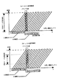
続いて、添付の図5は、上記に説明した多列検出器型CTにおける計測を説明する図であり、180度再構成と異位相データの取得方法を説明する図である。
【0021】
すなわち、多列検出器型CTでは、複数の列が同一スライス位置を通過し、また、その時の位相が各々異なることから、360度再構成では360度分のデータを、180度再構成では180度分のデータを、異なる位相で分割し、それらを複数の列で分担して再構成データを作成することとなる。なお、図5は、8列検出器型CTにおける螺旋ピッチ8の場合の計測図である。
【0022】
図5(a)は、8列全ての列を使用した場合の360度再構成であり、図5(b)は、8列のうち4列目から7列目までの4列を使用した場合の180度再構成を示す図である。図中において、細実線は各列における計測ラインを示しており、また、太実線は再構成画像を得る上で使用するデータ範囲を示している。そして、上記図5(b)からも明らかなように、螺旋ピッチ8において180度再構成を行う場合には、4列のデータのみでの再構成(位相角度範囲は、5/8π〜13/8π)が可能である。これは、不足するデータを対向するデータで補うことにより達成される。実際には8列あることから、使用する列範囲をかえる(例えば2列目から5列目)ことにより異なる位相角度範囲の画像を作成することが可能となる。
【0023】
次に、図6は、本発明に係る画像作成手順を示す図である。
図6(a)は、再構成画像加算方式による画像作成方法を示す。この方法では、まず、入力装置から計測パラメータの設定をする(ステップ1)。続いて、この設定された計測パラメータを基にして螺旋スキャンを行う(ステップ2)。このスキャンによって得られた各列の投影データから同一スライス位置における複数の異位相の再構成画像を作成するための加重関数を作成・適用して、異なる列範囲に対して螺旋補正を行い、同一スライス位置における複数の異位相投影データを作成する(ステップ3)。その後、得られた各加重投影データ(各異位相投影データ)を再構成する(ステップ4)。そして、得られた複数の再構成画像(同一スライス位置画像)を重み付け加算処理し(ステップ5)、最終的な再構成画像を得るものである。
【0024】
また、図6(b)は、投影データ加算方式による画像作成方法を示すが、この方法では、その開始後、ステップ1〜ステップ3は同じであるが、その後、上記図6に示すステップ4と5を逆転して、まず、各異位相投影データを重み付け加算処理し(ステップ5)、その後、各異位相投影データを再構成する(ステップ4)ことにより、最終的な再構成画像を得るものである。
【0025】
なお、ここで、重み付け加算用の位相の異なる再構成画像を得るに際しては、公知の断層写真像作成方法を一部の検出器列データ範囲に適用し、同様に、前記検出器列データ範囲とは異なる検出器列データ範囲に適用し、これを複数回繰り返すことにより複数の異なる断層写真像を作成してもかまわない。また、各異なる投影データ位相範囲は、各重み付け加算データ間で、相互に重なりあう位相範囲を持ってもかまわない。また、検出器列数の増加に伴い、X線ビーム傾斜角度による誤差影響が顕著になるため、ビーム傾斜角度を考慮した処理を行う方が望ましいであろう。
【0026】
以上に詳細に示したように、上述した本発明の様々な実施の形態に関する記述から、本発明の目的が達成されたことは明らかであろう。また、以上の説明では、本発明の実施の形態の詳細について記述すると共に、これらを図示したが、しかしながら、これらは説明及び例示のみを意図したものであって、本発明がこれらにのみ限定されるものではないことは明らかであろう。
【0027】
例えば、上記の本発明の実施の形態では、螺旋走査型CTにおいて、16列の多列検出器から16列の投影データを得、これに加重関数を適用することで、加重投影データ配列を得ているが、しかしながら、本発明はこれにのみ限定されず、例えば、2以上の列で構成される多列検出器又は平面検出器から、2以上の投影データ配列を得、これらを加重関数として適用することで加重投影配列を得てもよい。また、ヘリカルピッチについても、例えば「3」や「4」などの整数値に限定されるものではなく、投影データ列数より小さい値であれば、例えば「1.5」や「2.5」などといった少数値であってもよい。本実施の形態では1つのX線焦点によって単一回の撮影により、得られた投影データを用いているが、これは、同一スライス位置において、異なる位相を有するように、1つ以上のX線焦点によって、更には複数回の撮影によって、得られた投影データを用いてよい。
また、本発明は、画像再構成方法によって限定されるものではなく、いかなる画像再構成方法に適用してもよい。従って、本発明の範囲は、特許請求の範囲によってのみ限定されるべきものである。
【0028】
【発明の効果】
以上に詳細に説明したように、本発明になる多列検出器型X線CT装置とその断層写真像の作成方法によれば、多列検出器又は平面センサを有する螺旋走査X線CTスキャナにおいて、あらゆるヘリカルピッチによって得られた投影データから断層写真像を作成する場合において、また、作成された断層写真像から3次元画像を作成する場合において、ヘリカルピッチに依存することなく、各再構成データの位相に依存して発生する歪み(アーチフアクト)を補正することができ、これにより、より薄い断層写真像が作成できることから、より体軸分解能の高い、かつ、高画質な画像を作成することができる。
【図面の簡単な説明】
【図1】本発明の一実施の形態になる多列検出器型CT装置の全体構成を示す図である。
【図2】上記本発明の多列検出器型CT装置による螺旋スキャンを説明する図である。
【図3】上記多列検出器型CT装置におけるノーマルスキャンと螺旋スキャンとを示す図である。
【図4】上記多列検出器型CT装置のファンビームによる180度再構成とパラレルビームによる180度再構成を説明する図である。
【図5】上記多列検出器型CT装置における360度構成と180度再構成との投影データ位相範囲を説明する図である。
【図6】上記本発明の多列検出器型CT装置における2つの方式の画像作成フローを示す図である。
【符号の祝明】
1 X緑発生装置
2 コリメータ
3 患者テーブル
4 被検体
5 多列検出装置
6 スキャナ駆動装置
7 スキャナコントローラ
8 コリメータコントローラ
9 処理装置
10 高電圧発生装置
11 表示装置[0001]
BACKGROUND OF THE INVENTION
The present invention relates to a computer tomographic image (CT) that obtains a tomographic image by image processing with a computer of measurement data obtained by detecting transmitted X-rays from a subject irradiated with X-rays. The present invention relates to an X-ray CT apparatus having a multi-row detector in which detection elements are arranged in a plurality of rows in the body axis direction of a subject.
[0002]
[Prior art]
Conventionally, a spiral scanning CT (hereinafter referred to as a tomographic image) obtained by scanning a subject spirally with a scanner having a detector (hereinafter referred to as a single-row detector) comprising a single row of X-ray detectors. Single row detector CT) is already known. In such a single-row detector type CT, as a method for creating a tomographic image from the projection data obtained from the single-row X-ray detector by spiral scanning with a scanner, For example, after obtaining weighted projection data by applying a known helical correction weighting function such as “360 degree interpolation method”, “180 degree opposite interpolation method”, or “half scan method”, the weighted projection is performed. For example, a tomographic image is created by reconstructing data by, for example, a “filtered back projection method” or a “Fourier reconstruction method”.
[0003]
On the other hand, in recent years, instead of the single-row X-ray detector, a detection device (hereinafter referred to as a multi-row detection device) comprising X-ray detection elements arranged in a plurality of rows in the body axis direction of the subject is provided. Spiral scanning CT (hereinafter referred to as multi-row detector type CT) that obtains a tomographic image by spirally scanning is known. Even in such a multi-row detector type CT, when a tomographic image is obtained by spiral scanning of a subject, a tomographic image is created from a single projection data. In that case, when a single tomographic data is obtained from a projection data array obtained from a multi-row detector by spiral scanning and a tomographic image is created, for example, Japanese Patent Laid-Open No. 9-98968 and Japanese Patent Laid-Open No. 2000-702S7 As is known from the Gazette, the spiral correction is applied to all existing projection data arrays by applying a unique weighting function to all existing columns, and the resulting spiral correction data is reconstructed. By doing so, a tomographic image is created.
[0004]
Furthermore, a method of performing weighted addition processing on different slice position images to create a reconstructed output image, or a method of performing weighting in the projection angle direction on the projection data in order to obtain an equivalent effect, for example, JP-A-10-216120.
[0005]
[Problems to be solved by the invention]
However, in the conventional techniques described above, artifacts may occur strongly on the tomographic image reconstructed from the projection data array obtained by the helical scan, and the artifact may be “reconstructed”. May occur in a direction depending on each projection angle. Further, as proposed in the above Japanese Patent Laid-Open No. 10-216120, when performing weighted addition processing on different slice position images or weighting in the projection angle direction on the projection data, Since data having a spread in the body axis direction is used, there is a problem that the resolution in the body axis direction is deteriorated.
[0006]
Therefore, the present invention has been made in view of such circumstances in the prior art, and in a CT apparatus equipped with a multi-row detector, a tomographic image is reconstructed from a projection data array obtained by spiral scanning. X-ray CT capable of obtaining a higher-quality tomographic image by correcting distortion (artifact) generated in a specific direction in each phase without reducing the body axis resolution of the subject. The object is to provide a device.
[0007]
[Means for Solving the Problems]
The present invention comprises an X-ray source and a plurality of two-dimensionally arranged X-ray detection elements, facing each other with the object sandwiched between the X-ray source, and the object irradiated from the X-ray source. An X-ray detector for measuring X-rays transmitted through the object, and the object to be rotated around the rotation axis relative to the object with the X-ray source and the X-ray detector. A scanner that performs a helical scan by moving an object relative to the X-ray source and the X-ray detector to perform a helical scan, and projection data collected by the X-ray detector by the helical scan An X-ray CT apparatus including an image processing apparatus for creating a tomographic image of the object from
The image processing apparatus creates a tomogram by reconstructing data obtained by combining a plurality of projection data having different phase angle ranges of the rotation at the same position on the rotation axis of the object. An X-ray CT apparatus is disclosed.
[0008]
Further, according to the present invention, the image processing apparatus includes a selection device that selects the plurality of different projection data from the plurality of element rows of the two-dimensionally arranged X-ray detector, and is selected by the selection device. An X-ray CT apparatus is disclosed in which an image is reconstructed using detection data of the element array and opposite data of the data.
[0009]
Furthermore, the present invention comprises an X-ray source and a plurality of two-dimensionally arranged X-ray detection elements, facing each other with the object sandwiched between the X-ray source, and being irradiated onto the object from the X-ray source. An X-ray detector that measures X-rays transmitted through the object, and circulates the X-ray source and the X-ray detector around the rotation axis relative to the object and the object. A scanner that performs helical scanning by moving an object relative to the X-ray source and the X-ray detector to perform spiral scanning, and projection data collected by the X-ray detector by the helical scanning An X-ray CT apparatus including an image processing apparatus for creating a tomographic image of the object from
The image processing apparatus reconstructs a plurality of images having different phases from a plurality of projection data having different phase angle ranges of the rotation at the same position on the rotation axis of the object, An X-ray CT apparatus is disclosed in which a tomographic image is created by adding the images.
[0010]
Further, according to the present invention, the image processing apparatus uses the weight function which is a function of the phase range of the rounds corresponding to each of the plurality of different projection data and the image obtained from the data obtained by weighting and combining them. An X-ray CT apparatus characterized by reconfiguration is disclosed.
[0012]
DETAILED DESCRIPTION OF THE INVENTION
Hereinafter, embodiments of the present invention will be described in detail with reference to the accompanying drawings. Here, an X-ray spiral scanning CT apparatus that creates a tomographic image of a subject by irradiating the subject with X-rays and image-processing the measurement data obtained by detecting the transmitted X-rays with a computer. Show.
[0013]
First, FIG. 1 shows a so-called multi-row detector type X-ray spiral scanning CT apparatus equipped with a multi-row detector comprising a plurality of detector elements arranged in multiple rows as an X-ray detector according to the present invention. A schematic configuration is shown. As shown in the figure, this multi-row detector type helical scanning CT apparatus includes an
[0014]
The spiral scanning CT apparatus further includes a scanner driving device 6 for allowing the scanner 7 to rotate continuously around the subject 4 on the patient table 3, and the scanner 7. For creating a tomographic image based on measurement data obtained by the scanner controller 71 for controlling the collimator, the collimator controller 8 installed in the scanner controller 71 for controlling the collimator, and the scanner 7. In addition to the pre-processing / image reconstruction processing for executing the predetermined image processing, the image processing device 9 for performing various analysis processing, and the high voltage for supplying the
[0015]
Next, FIG. 2 attached shows a method for scanning the subject 4 by the above-described multi-row detector type helical scanning CT apparatus, in particular, the helical scanning operation by the scanner 7. In this figure, as described above, the scanner 7 equipped with the
[0016]
Next, FIG. 3 is an explanatory diagram for explaining a spiral scan and a normal scan according to the present invention among the scans performed by the above-described scanning CT apparatus.
[0017]
3A shows a so-called normal scan (circular locus) in which the X-ray focal point is not moved with respect to the subject, while FIG. 3B shows an X-ray focal point with respect to the subject. Represents a spiral scan (spiral trajectory). When the image is captured by a spiral scan as shown in FIG. 3B, the spiral locus is interpolated into a normal scan circle locus as shown in FIG. Perform reconfiguration. This is because, when image reconstruction is performed without performing such interpolation, a false image (artifact) is generated in the obtained tomographic image due to so-called spiral distortion.
[0018]
Next, FIG. 4 is a diagram for explaining 180-degree reconstruction (half reconstruction) in the fan beam and the parallel beam in the single-row detector type CT. Usually, in the third generation CT, the X-ray irradiated from the X-ray generator is a fan beam as shown in FIG. In the third generation CT, in some cases (for example, for speeding up), a parallel beam rearranged by a rebinning process as shown in FIG. 4B may be used.
[0019]
4A and 4B, the minimum projection angle for creating a reconstructed image is an angle from S1 to S2 (180 degrees + fan angle) in the figure. An image obtained at this minimum projection angle is generally called a “180-degree reconstructed image (half-scan image)”. Conversely, when reconstruction is performed from projection data for 360 degrees, this is referred to as “360-degree reconstruction (full reconstruction)”, and the reconstructed image obtained thereby is “360-degree reconstruction image ( Full scan image) ". Here, it is also possible to perform the 180-degree reconstruction by normalizing redundant data even in data larger than the minimum projection angle (= 180 degrees + fan angle) and smaller than 360 degrees. .
[0020]
Next, FIG. 5 attached is a diagram for explaining the measurement in the multi-row detector type CT described above, and is a diagram for explaining a 180-degree reconstruction and a method for acquiring different phase data.
[0021]
That is, in the multi-row detector CT, a plurality of rows pass through the same slice position, and the phases at that time are different from each other, so that data for 360 degrees is obtained in 360-degree reconstruction, and data in 180-degree reconstruction is 180. The data for the degree is divided at different phases, and these data are divided into a plurality of columns to generate reconstructed data. FIG. 5 is a measurement diagram in the case of the spiral pitch 8 in the 8-row detector type CT.
[0022]
FIG. 5A shows a 360-degree reconstruction when all eight columns are used, and FIG. 5B shows a case where four columns from the fourth column to the seventh column are used among the eight columns. It is a figure which shows 180 degree | times reconstruction. In the figure, a thin solid line indicates a measurement line in each column, and a thick solid line indicates a data range used for obtaining a reconstructed image. As is clear from FIG. 5 (b), when the reconstruction is performed 180 degrees at the helical pitch 8, reconstruction with only four columns of data (the phase angle range is 5 / 8π to 13 / 8π) is possible. This is accomplished by supplementing the missing data with the opposing data. Since there are actually eight columns, it is possible to create images with different phase angle ranges by changing the column range to be used (for example, from the second column to the fifth column).
[0023]
Next, FIG. 6 is a diagram showing an image creation procedure according to the present invention.
FIG. 6A shows an image creation method based on the reconstructed image addition method. In this method, first, measurement parameters are set from the input device (step 1). Subsequently, a spiral scan is performed based on the set measurement parameters (step 2). Create and apply a weighting function to create a plurality of different-phase reconstructed images at the same slice position from the projection data of each column obtained by this scan, and perform helical correction for different column ranges, A plurality of different phase projection data at the same slice position is created (step 3). Thereafter, each obtained weighted projection data (each different phase projection data) is reconstructed (step 4). Then, the obtained plurality of reconstructed images (same slice position images) are weighted and added (step 5) to obtain a final reconstructed image.
[0024]
FIG. 6B shows an image creation method based on the projection data addition method. In this method,
[0025]
Here, when obtaining a reconstructed image with different phases for weighted addition, a known tomographic image creation method is applied to a part of the detector row data range, and similarly, the detector row data range and May be applied to different detector row data ranges, and a plurality of different tomographic images may be created by repeating this multiple times. Further, the different projection data phase ranges may have phase ranges that overlap each other between the respective weighted addition data. Also, as the number of detector rows increases, the influence of errors due to the X-ray beam tilt angle becomes more prominent, so it is desirable to perform processing in consideration of the beam tilt angle.
[0026]
As detailed above, it will be apparent from the above description of various embodiments of the invention that the objects of the invention have been achieved. Further, in the above description, details of the embodiments of the present invention are described and illustrated, however, these are intended only for explanation and illustration, and the present invention is not limited thereto. It will be clear that it is not.
[0027]
For example, in the above-described embodiment of the present invention, in helical scanning CT, 16 rows of projection data are obtained from 16 rows of multi-row detectors, and a weighting function is applied thereto to obtain a weighted projection data array. However, the present invention is not limited to this. For example, two or more projection data arrays are obtained from a multi-row detector or a flat detector composed of two or more columns, and these are used as a weighting function. A weighted projection array may be obtained by application. Further, the helical pitch is not limited to an integer value such as “3” or “4”, and may be “1.5” or “2.5” as long as it is smaller than the number of projection data strings. It may be a decimal value such as. In the present embodiment, projection data obtained by single imaging with one X-ray focal point is used. This is because one or more X-rays have different phases at the same slice position. You may use the projection data obtained by the focus, and also by several times of photography.
Further, the present invention is not limited to the image reconstruction method, and may be applied to any image reconstruction method. Accordingly, the scope of the invention should be limited only by the claims.
[0028]
【The invention's effect】
As described in detail above, according to the multi-row detector type X-ray CT apparatus and the tomographic image creation method thereof according to the present invention, in a spiral scanning X-ray CT scanner having a multi-row detector or a planar sensor. When creating a tomographic image from projection data obtained at any helical pitch, and when creating a three-dimensional image from the created tomographic image, each reconstruction data is independent of the helical pitch. The distortion (artifact) that occurs depending on the phase of the image can be corrected. As a result, a thinner tomographic image can be created. it can.
[Brief description of the drawings]
FIG. 1 is a diagram showing an overall configuration of a multi-row detector CT apparatus according to an embodiment of the present invention.
FIG. 2 is a diagram for explaining a helical scan by the multi-row detector CT apparatus of the present invention.
FIG. 3 is a diagram showing a normal scan and a spiral scan in the multi-row detector type CT apparatus.
FIG. 4 is a diagram for explaining 180-degree reconstruction with a fan beam and 180-degree reconstruction with a parallel beam in the multi-row detector CT apparatus.
FIG. 5 is a diagram for explaining projection data phase ranges of a 360-degree configuration and a 180-degree reconstruction in the multi-row detector CT apparatus.
FIG. 6 is a diagram showing two types of image creation flows in the multi-row detector CT apparatus of the present invention.
[Celebration of sign]
DESCRIPTION OF SYMBOLS 1 X
Claims (4)
前記画像処理装置は、前記対象物の前記周回軸上の同一位置において前記周回の位相角度範囲の異なる複数の投影データを組み合わせたデータを再構成して断層像を作成する、ことを特徴とするX線CT装置。An X-ray source and a plurality of two-dimensionally arranged X-ray detection elements, facing the X-ray source with an object sandwiched therebetween, irradiated from the X-ray source to the object, and transmitted through the object An X-ray detector that measures X-rays, and circulates the X-ray source and the X-ray detector relative to the object around a rotation axis and moves the object to the X A spiral scanning is performed by moving along the circumferential axis relative to a radiation source and the X-ray detector, and the object is obtained from the projection data collected by the X-ray detector by the spiral scanning. An X-ray CT apparatus including an image processing apparatus for creating a tomographic image of
The image processing apparatus creates a tomogram by reconstructing data obtained by combining a plurality of projection data having different phase angle ranges of the rotation at the same position on the rotation axis of the object. X-ray CT system.
前記画像処理装置は、前記対象物の前記周回軸上の同一位置において、前記周回の位相角度範囲の異なる複数の投影データから複数の異位相の画像を再構成し、前記再構成された複数の画像を加算して断層像を作成する、ことを特徴とするX線CT装置。An X-ray source and a plurality of two-dimensionally arranged X-ray detection elements, facing the X-ray source with an object sandwiched therebetween, irradiated from the X-ray source to the object, and transmitted through the object An X-ray detector that measures X-rays, and circulates the X-ray source and the X-ray detector around a rotation axis relative to the object and moves the object to the X-ray. A scanner that performs a helical scan by moving along the rotational axis relative to the source and the X-ray detector, and the projection data collected by the X-ray detector by the helical scan of the object. An X-ray CT apparatus including an image processing apparatus for creating a tomographic image,
The image processing apparatus reconstructs a plurality of images having different phases from a plurality of projection data having different phase angle ranges of the rotation at the same position on the rotation axis of the object, An X-ray CT apparatus characterized in that a tomographic image is created by adding the images.
Priority Applications (4)
| Application Number | Priority Date | Filing Date | Title |
|---|---|---|---|
| JP2001326669A JP4025530B2 (en) | 2001-10-24 | 2001-10-24 | X-ray CT system |
| PCT/JP2002/010997 WO2003034920A1 (en) | 2001-10-24 | 2002-10-23 | Multi-row detector x-ray ct apparatus and method for creating tomogram |
| CNB028212835A CN100411591C (en) | 2001-10-24 | 2002-10-23 | Multi-row detector x-ray ct apparatus and method for creating tomogram |
| US10/493,678 US7221730B2 (en) | 2001-10-24 | 2002-10-23 | Multi-row detector x-ray CT apparatus and method for creating tomogram |
Applications Claiming Priority (1)
| Application Number | Priority Date | Filing Date | Title |
|---|---|---|---|
| JP2001326669A JP4025530B2 (en) | 2001-10-24 | 2001-10-24 | X-ray CT system |
Publications (3)
| Publication Number | Publication Date |
|---|---|
| JP2003126080A JP2003126080A (en) | 2003-05-07 |
| JP2003126080A5 JP2003126080A5 (en) | 2005-06-30 |
| JP4025530B2 true JP4025530B2 (en) | 2007-12-19 |
Family
ID=19143016
Family Applications (1)
| Application Number | Title | Priority Date | Filing Date |
|---|---|---|---|
| JP2001326669A Expired - Fee Related JP4025530B2 (en) | 2001-10-24 | 2001-10-24 | X-ray CT system |
Country Status (4)
| Country | Link |
|---|---|
| US (1) | US7221730B2 (en) |
| JP (1) | JP4025530B2 (en) |
| CN (1) | CN100411591C (en) |
| WO (1) | WO2003034920A1 (en) |
Families Citing this family (8)
| Publication number | Priority date | Publication date | Assignee | Title |
|---|---|---|---|---|
| JP2005137390A (en) * | 2003-11-04 | 2005-06-02 | Ge Medical Systems Global Technology Co Llc | Ct image creating method and x-ray ct equipment |
| ATE380373T1 (en) * | 2004-01-29 | 2007-12-15 | Koninkl Philips Electronics Nv | WINDMILL ARTIFACT REDUCTION IN MULTI-SLICE CT RECONSTRUCTION |
| US20050226365A1 (en) * | 2004-03-30 | 2005-10-13 | Kabushiki Kaisha Toshiba | Radius-in-image dependent detector row filtering for windmill artifact reduction |
| US7003070B1 (en) * | 2004-08-03 | 2006-02-21 | William Barry Chen | Upright CT scanner |
| ATE524795T1 (en) * | 2005-03-09 | 2011-09-15 | Koninkl Philips Electronics Nv | DEVICE AND METHOD FOR PROVIDING A 2D REPRESENTATION OF 3D IMAGE DATA REPRESENTING AN ANATOMIC LUMINAL TREE STRUCTURE |
| JP5728304B2 (en) * | 2011-06-21 | 2015-06-03 | 株式会社日立メディコ | X-ray CT apparatus and image reconstruction method |
| JP7195825B2 (en) * | 2017-09-12 | 2022-12-26 | キヤノンメディカルシステムズ株式会社 | X-ray computed tomography device and image generation device |
| JP2019158534A (en) * | 2018-03-12 | 2019-09-19 | 株式会社ミツトヨ | X-ray ct apparatus for measurement and method for generating fault image |
Family Cites Families (17)
| Publication number | Priority date | Publication date | Assignee | Title |
|---|---|---|---|---|
| JP2825446B2 (en) * | 1993-09-06 | 1998-11-18 | 株式会社東芝 | X-ray computed tomography device |
| US5541971A (en) * | 1993-09-06 | 1996-07-30 | Kabushiki Kaisha Toshiba | X-ray computerized tomography apparatus |
| US5513236A (en) * | 1995-01-23 | 1996-04-30 | General Electric Company | Image reconstruction for a CT system implementing a dual fan beam helical scan |
| JP2914891B2 (en) * | 1995-07-05 | 1999-07-05 | 株式会社東芝 | X-ray computed tomography apparatus |
| US5559847A (en) | 1995-12-06 | 1996-09-24 | General Electric Company | Systems, methods and apparatus for reconstructing images in a CT system implementing a helical scan |
| US5838756A (en) * | 1996-01-08 | 1998-11-17 | Kabushiki Kaisha Toshiba | Radiation computed tomography apparatus |
| US5974110A (en) * | 1997-11-26 | 1999-10-26 | General Electric Company | Helical reconstruction algorithm |
| US6028909A (en) * | 1998-02-18 | 2000-02-22 | Kabushiki Kaisha Toshiba | Method and system for the correction of artifacts in computed tomography images |
| DE19832275B4 (en) * | 1998-07-17 | 2006-09-14 | Siemens Ag | Method for reconstructing images from measured values obtained by means of a CT scanner by spiral scanning of the examination subject and CT apparatus for performing the method |
| DE19832276C2 (en) | 1998-07-17 | 2002-10-24 | Siemens Ag | Process for the reconstruction of measurement values obtained from a CT device by spiral scanning |
| DE19854947B4 (en) * | 1998-11-27 | 2005-01-05 | Siemens Ag | Image reconstruction method for a spiral CT device and spiral CT device for performing such a method |
| JP4406106B2 (en) * | 1999-02-04 | 2010-01-27 | 株式会社東芝 | X-ray CT system |
| JP2000278702A (en) | 1999-03-26 | 2000-10-06 | Nikon Corp | Interpolation processor and recording medium storing interpolation processing program |
| JP4726287B2 (en) * | 1999-10-20 | 2011-07-20 | 株式会社日立メディコ | Multi-slice X-ray CT system |
| JP4538142B2 (en) * | 2000-09-06 | 2010-09-08 | 株式会社日立メディコ | Tomographic image creating method and tomographic image creating apparatus. |
| DE10207623B4 (en) * | 2002-02-22 | 2004-05-06 | Siemens Ag | Procedures for computed tomography as well as computed tomography (CT) device |
| JP2005137390A (en) * | 2003-11-04 | 2005-06-02 | Ge Medical Systems Global Technology Co Llc | Ct image creating method and x-ray ct equipment |
-
2001
- 2001-10-24 JP JP2001326669A patent/JP4025530B2/en not_active Expired - Fee Related
-
2002
- 2002-10-23 US US10/493,678 patent/US7221730B2/en not_active Expired - Fee Related
- 2002-10-23 WO PCT/JP2002/010997 patent/WO2003034920A1/en active Application Filing
- 2002-10-23 CN CNB028212835A patent/CN100411591C/en not_active Expired - Fee Related
Also Published As
| Publication number | Publication date |
|---|---|
| JP2003126080A (en) | 2003-05-07 |
| CN100411591C (en) | 2008-08-20 |
| US7221730B2 (en) | 2007-05-22 |
| WO2003034920A1 (en) | 2003-05-01 |
| US20040258197A1 (en) | 2004-12-23 |
| CN1575148A (en) | 2005-02-02 |
Similar Documents
| Publication | Publication Date | Title |
|---|---|---|
| JP4646810B2 (en) | Tomographic image reconstruction method and tomographic apparatus | |
| JP5142664B2 (en) | X-ray computed tomography system | |
| JP3866431B2 (en) | X-ray CT system | |
| JP4360817B2 (en) | Radiation tomography equipment | |
| JP3682308B2 (en) | Computer tomography apparatus and method for generating an image of an object to be imaged | |
| US20040131140A1 (en) | Method for computed tomography of a periodically moving object to be examined, and a CT unit for carrying out this method | |
| JP2007000408A (en) | X-ray ct apparatus | |
| JP2001512346A (en) | Scanning axis displacement spiral scanner | |
| JP2008006032A (en) | X-ray ct scanner and x-ray ct scanning method | |
| US20040086075A1 (en) | Titled gantry helical cone-beam Feldkamp reconstruction for multislice CT | |
| JPH08263638A (en) | System and method for creation of tomographic image of object | |
| JP3455041B2 (en) | X-ray CT system | |
| KR20070058997A (en) | X-ray ct imaging method and x-ray ct apparatus | |
| JP4977007B2 (en) | Multiple focus acquisition methods and apparatus | |
| JP4025530B2 (en) | X-ray CT system | |
| EP2506772B1 (en) | Method and system for high resolution nutated slice reconstruction using quarter detector offset | |
| JP2007159878A (en) | X-ray ct apparatus and method of reconstructing x-ray ct image of the same | |
| JP2006187453A (en) | X-ray ct apparatus | |
| JP2005224637A (en) | X-ray ct apparatus and method for correcting misalignment thereof | |
| JP4406106B2 (en) | X-ray CT system | |
| JP2004519293A (en) | High-speed computed tomography method | |
| JPH11206753A (en) | X-ray radiographic device | |
| JP2004113271A (en) | Ct scanner | |
| JP3802650B2 (en) | X-ray CT system | |
| JP4551612B2 (en) | Computed tomography equipment |
Legal Events
| Date | Code | Title | Description |
|---|---|---|---|
| A521 | Request for written amendment filed |
Free format text: JAPANESE INTERMEDIATE CODE: A523 Effective date: 20041019 |
|
| A621 | Written request for application examination |
Free format text: JAPANESE INTERMEDIATE CODE: A621 Effective date: 20041019 |
|
| A131 | Notification of reasons for refusal |
Free format text: JAPANESE INTERMEDIATE CODE: A131 Effective date: 20070508 |
|
| A521 | Request for written amendment filed |
Free format text: JAPANESE INTERMEDIATE CODE: A523 Effective date: 20070706 |
|
| TRDD | Decision of grant or rejection written | ||
| A01 | Written decision to grant a patent or to grant a registration (utility model) |
Free format text: JAPANESE INTERMEDIATE CODE: A01 Effective date: 20071002 |
|
| A61 | First payment of annual fees (during grant procedure) |
Free format text: JAPANESE INTERMEDIATE CODE: A61 Effective date: 20071005 |
|
| R150 | Certificate of patent or registration of utility model |
Free format text: JAPANESE INTERMEDIATE CODE: R150 |
|
| FPAY | Renewal fee payment (event date is renewal date of database) |
Free format text: PAYMENT UNTIL: 20101012 Year of fee payment: 3 |
|
| FPAY | Renewal fee payment (event date is renewal date of database) |
Free format text: PAYMENT UNTIL: 20101012 Year of fee payment: 3 |
|
| FPAY | Renewal fee payment (event date is renewal date of database) |
Free format text: PAYMENT UNTIL: 20111012 Year of fee payment: 4 |
|
| FPAY | Renewal fee payment (event date is renewal date of database) |
Free format text: PAYMENT UNTIL: 20111012 Year of fee payment: 4 |
|
| FPAY | Renewal fee payment (event date is renewal date of database) |
Free format text: PAYMENT UNTIL: 20121012 Year of fee payment: 5 |
|
| FPAY | Renewal fee payment (event date is renewal date of database) |
Free format text: PAYMENT UNTIL: 20121012 Year of fee payment: 5 |
|
| FPAY | Renewal fee payment (event date is renewal date of database) |
Free format text: PAYMENT UNTIL: 20131012 Year of fee payment: 6 |
|
| S111 | Request for change of ownership or part of ownership |
Free format text: JAPANESE INTERMEDIATE CODE: R313111 |
|
| S533 | Written request for registration of change of name |
Free format text: JAPANESE INTERMEDIATE CODE: R313533 |
|
| R350 | Written notification of registration of transfer |
Free format text: JAPANESE INTERMEDIATE CODE: R350 |
|
| LAPS | Cancellation because of no payment of annual fees |