JP4025501B2 - Music generator - Google Patents
Music generator Download PDFInfo
- Publication number
- JP4025501B2 JP4025501B2 JP2000344904A JP2000344904A JP4025501B2 JP 4025501 B2 JP4025501 B2 JP 4025501B2 JP 2000344904 A JP2000344904 A JP 2000344904A JP 2000344904 A JP2000344904 A JP 2000344904A JP 4025501 B2 JP4025501 B2 JP 4025501B2
- Authority
- JP
- Japan
- Prior art keywords
- sound
- data
- note data
- note
- sub cpu
- Prior art date
- Legal status (The legal status is an assumption and is not a legal conclusion. Google has not performed a legal analysis and makes no representation as to the accuracy of the status listed.)
- Expired - Fee Related
Links
- 230000015572 biosynthetic process Effects 0.000 claims abstract description 18
- 238000003786 synthesis reaction Methods 0.000 claims abstract description 18
- 238000000034 method Methods 0.000 claims description 28
- 230000002194 synthesizing effect Effects 0.000 claims description 10
- 238000013500 data storage Methods 0.000 claims 20
- 238000010586 diagram Methods 0.000 description 7
- 238000006243 chemical reaction Methods 0.000 description 6
- 230000000694 effects Effects 0.000 description 5
- 230000003111 delayed effect Effects 0.000 description 2
- 230000006870 function Effects 0.000 description 1
- 238000004519 manufacturing process Methods 0.000 description 1
- 230000001360 synchronised effect Effects 0.000 description 1
Images


Classifications
-
- G—PHYSICS
- G10—MUSICAL INSTRUMENTS; ACOUSTICS
- G10H—ELECTROPHONIC MUSICAL INSTRUMENTS; INSTRUMENTS IN WHICH THE TONES ARE GENERATED BY ELECTROMECHANICAL MEANS OR ELECTRONIC GENERATORS, OR IN WHICH THE TONES ARE SYNTHESISED FROM A DATA STORE
- G10H7/00—Instruments in which the tones are synthesised from a data store, e.g. computer organs
- G10H7/002—Instruments in which the tones are synthesised from a data store, e.g. computer organs using a common processing for different operations or calculations, and a set of microinstructions (programme) to control the sequence thereof
- G10H7/004—Instruments in which the tones are synthesised from a data store, e.g. computer organs using a common processing for different operations or calculations, and a set of microinstructions (programme) to control the sequence thereof with one or more auxiliary processor in addition to the main processing unit
Abstract
Description
【0001】
【発明の属する技術分野】
本発明は、楽音発生技術にかかり、特に音データの生成をハードウェアとソフトウェアに分散して行う技術に関する。
【0002】
【従来の技術】
楽譜データを読み込んで、その楽譜データに示された音を出力する、コンピュータ制御の楽音発生装置が知られている。この楽音発生装置では、通常、コンピュータが音響処理専用のサウンドプロセッサを制御して音の合成を行い、D/A変換した後、スピーカを鳴らしている。
【0003】
【発明が解決しようとする課題】
しかしながら、ユーザニーズの高まり等から、よりリアルな、臨場感あるサウンドが求められるようになってきている。従来の技術では、サウンドプロセッサを新たに設計し、新しいハードウェアを製造して楽音発生装置に搭載すればかかるニーズに対応できる。ところが、新しいハードウェアの開発にはコストおよび時間がかかる。従って、ハードウェアで対応することは容易ではない。
【0004】
一方、すべての処理をソフトウェアで行うと、処理に要する時間がかかりすぎて、音が遅れるという問題がある。これは、画像と音を組み合わせて出力するようなときは、特に問題となる。
【0005】
そこで、ソフトウェア処理とハードウェア処理とを組み合わせた楽音発生技術を提供することを目的とする。
【0006】
【課題を解決するための手段】
前記目的を達成するため、本発明では以下の処理を行う。すなわち、楽譜データのうちの一部を取り込み、当該取り込んだ楽譜データに基づいて、第1のデジタルデータを出力する。この処理は音合成回路で行う。受け付けた楽譜データのうちの他の一部を読み込み、当該読み込んだ楽譜データに基づいて、第2のデジタルデータを生成する。この処理は、当該処理を記述したプログラムを読み込んだプロセッサで行う。そして、第1および第2のデジタルデータを、アナログ信号に変換する。この処理は、D/A変換器で行う。
【0007】
【発明の実施の形態】
以下、本発明の実施形態について、図面を用いて説明する。
【0008】
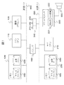
図1は、本発明の実施形態に係る楽音発生装置におけるハードウェア構成を示す図である。本実施形態にかかる楽音発生装置は、外部からの入力操作を受付けて、音と画像を出力するエンターテインメント装置に適用すると好適である。
【0009】
本実施形態に係る楽音発生装置は、メインCPU(Central Processing Unit)110と、メモリ120と、画像プロセッサ130と、サブCPU210と、サウンドプロセッサ220と、メモリ230と、バッファ240と、スピーカ300とを備える。そして、メインCPU110と、メモリ120と、画像プロセッサ130とが高速バス150で接続され、サブCPU210と、サウンドプロセッサ220と、メモリ230と、バッファ240とが低速バス250で接続されている。さらに、高速バス150と低速バス250とが、バスインターフェース240を介して接続されている。
【0010】
メモリ120には、サウンドライブラリ310、および、音源ファイル330が記憶されている。メモリ230には、サウンドライブラリ320、および、楽譜データ340が記憶されている。
【0011】
バッファ240には、サブCPU210からメインCPU110へ転送するデータを格納するMC領域241と、サブCPU210からサウンドプロセッサ220へ転送するデータを格納するSP領域242と、メインCPU110からサウンドプロセッサへ転送するPCMデータ350を記憶するPCM領域243とを有する。
【0012】
メインCPU110は、60Hzの周期で動作する。メインCPU110は、例えば、処理能力が300MIPS程度のものを用いてもよい。本楽音発生装置をエンタテインメント装置に適用したとき、メインCPU110は、主に画像出力のための処理を行い、画像プロセッサ130を制御する。つまり、図示しないクロック発生器が発生するクロック信号に基づき、1/60秒を1周期とし、各周期内で所定の画像出力の処理を行う。その様子を図示したものが、図4(a)である。メインCPU110は、1/60秒ごとに画像関係の処理Gを行う。その周期内で行うべき処理が早く終わった場合には、次の周期が到来するまで処理を行わない。この空き時間Bを利用して、以下に説明する音響出力に関する処理を行う(図4(c)参照)。
【0013】
音響出力に関する処理は、サウンドライブラリ310から所定のプログラムを読み込んで実行する。以下、その詳細について説明する。
【0014】
メインCPU110は、バッファ240のMC領域241から音符データ350を読み込む。読み込んだデータに基づいて、メインCPU110は音を合成し、PCM(Pulse Code Modulation)データを生成する。音符データ350とは、例えば、図2および3に示すような、音色および、その音色についての音の状態を示す記述を含むテキストデータである。音符データは、たとえば、音の発音、音の停止、および、発音する音の高さのうちの、少なくともいずれかに関する音の状態を示す。音符データ350は、サブCPU210が生成して、バッファ240のMC領域241またはSP領域242に格納する。音符データ350は、サブCPU210が各周期において出力するブロック351に構成される。
【0015】
図2に示す音符データの例は、4つのブロックに分割されている。各ブロック351には、少なくとも、当該ブロックの大きさを示す"Data size=XX"と、当該ブロックが生成された時刻を示す"Time code=NN"という記述が含まれる。このタイムコードが示す時刻は、ミリ秒単位に表される。ただし、この時刻は他の音符データとの相対的な時刻を把握するためのものであり、現実の時刻と一致している必要はない。また、タイムコードの代りに、データの生成された順序を判別可能なシリアル番号を用いてもよい。
【0016】
さらにデータブロック351aに含まれる“Program Change P0=2”、“Program Change P1=80”は、それぞれ「パート0には識別子が2の楽器を設定する」、「パート1には識別子が80の楽器を設定する」という意味である。また、"Volume P0=90"、"Volume P1=100"は、それぞれ「パート0の音量を90とする」、「パート1の音量を100とする」という意味である。
【0017】
図3のデータブロック351bに含まれる"Key on P0=60"、"Key on P1=64"は、それぞれ、「パート0を60という音(中央ド)で鳴らす」、「パート0を64という音(中央ミ)で鳴らす」という意味である。データブロック351cに含まれる"Key on P1=67"は、「パート1を67という音(中央ソ)で鳴らす」という意味である。データブロック351dに含まれる"Key off P0=60"、"Key off P1=64"は、それぞれ、「パート0の60という音(中央ド)の出力を停止する」、「パート0の64という音(中央ミ)の出力を停止する」という意味である。これらの音符データ350は、サブCPU210が生成して、バッファ240のMC領域241に格納する。
【0018】
PCMデータ360とは、音符データ350に示された各パートごとの音の状態に相当する音データを、音源ファイル330から取り出して合成し、符号化したものである。PCMデータ360は、図5に示すように、音符データ350の各データブロック351に対応したブロック361に分けて生成され、バッファ240のPCM領域243に格納される。
【0019】
画像プロセッサ130は、メインCPU110の制御下で、図示しない表示装置に画像を表示させるための処理を行う。
【0020】
サブCPU210は、240Hz〜480Hzの周期で動作する。サブCPU210は、例えば、処理能力が30MIPS程度のものを用いてもよい。以下の各処理は、いずれもサウンドライブラリ320から所定のプログラムを読み込んで実行する。
【0021】
サブCPU210は、メモリ230から楽譜データ340を読み込んで、図2および図3に示すような音符データ350を生成する。生成した音符データ350は、バッファ240へ格納される。そのうち、メインCPU110が処理すべき音符データ350はMC領域241へ、サウンドプロセッサ220が処理すべき音符データ350はSP領域242へ、それぞれ記憶される。
【0022】
ここで、例えば、サウンドプロセッサ220が処理すべき音符データ350は、ベースサウンドに関するものとしてもよい。メインCPU110が処理すべき音符データ350は、メロディーラインに関するもの、または、特殊効果を必要とする処理に関するものとしてもよい。
【0023】
サウンドプロセッサ220は、サブCPU210の制御下で、スピーカ300に出力させる音の生成を行う。具体的には、サウンドプロセッサ220は、音合成回路221と、D/A変換回路222とを備える。音合成回路221は、サブCPU210が生成した音符データ350をSP領域242から読み込んで、符号化された合成音のPCMデータ360を出力する。D/A変換回路222は、音合成回路221が生成したPCMデータ360および、メインCPU110が生成したPCMデータ360をアナログの電圧信号に変換して、これをスピーカ300へ出力する。
【0024】
サウンドライブラリ310、320は、本楽音発生装置で音を出力するための処理を行うプログラムのモジュールが格納されている。例えば、楽譜データ340の読み込み等を行う入力処理モジュール、音の合成を行う音合成処理モジュール、サウンドプロセッサを制御するサウンドプロセッサ制御モジュール、フィルタ処理や、エコー処理等の特殊効果をつけるための特殊効果モジュール等が含まれる。
【0025】
音源ファイル330は、さまざまな楽器等のさまざまな音を合成するための基となる音源データを記憶している。
【0026】
楽譜データ340は、音楽の譜面で表された情報を、コンピュータ上に取りこんだデータである。
【0027】
次に、メインCPU110とサブCPU210の動作タイミングについて、図4を用いて説明する。図4に示すいずれの図も、横軸は時間を表す。
【0028】
図4(a)は、メインCPU110が画像に関する処理Gだけを行っているときの様子を示すタイミングチャートである。メインCPU110は、1/60で周期的に動作する。各周期の起点Aから当該周期内で処理すべき画像処理を開始する。そして、その処理が終了すると、メインCPU110は、次の周期が来るまで処理を行わない。すなわち、CPUに空き時間B(図中の斜線部分)ができる。
【0029】
図4(b)は、サブCPU210が音符データ350の生成・出力処理Sだけを行っているときの様子を示すタイミングチャートである。ここでは、サブCPU210が、1/240秒周期で動作する場合を考える。サブCPU210においても、メインCPU110と同様に、各周期の起点Aから当該周期内で処理すべき処理を開始する。そして、音符データの生成および出力が終了すると、次の周期が来るまでCPUの空き時間Bとなる。なお、サブCPU210が生成する音符データ350は、サウンドプロセッサ220が直接処理するものと、メインCPU110が処理した後、サウンドプロセッサ200へ転送されるものがある。
【0030】
図4(c)は、メインCPU110が空き時間Bに音合成処理を行う場合のタイミングチャートである。周期T2を例にとって説明する。周期t3〜t6の間にサブCPU210が生成した音符データ350が、バッファ240に格納されている。このうち、MC領域241に記憶されている音符データ350を図2に示す。メインCPU110はこの4つのブロック351の音符データ350を読み込み、所定の処理を行う。
【0031】
このとき、メインCPU110は、タイムコードを参照してタイムコードの順番に、ブロック351単位に、PCMデータ360の生成処理Pを行う。ここで、サブCPU210の4周期分のデータをメインCPU110の1周期内で処理するため、当該4周期分のデータを一括して処理することも可能である。しかし、一括処理すると、本来、1/240秒の精度で音の合成を行うことが可能であるのに、それが1/60秒の精度に低下する。上記のように、各ブロック単位にPCMデータの生成処理を行うことで、精度の低下を防止することができる。
【0032】
また、メインCPU110が画像に関する処理Gを行っている最中に、サブCPU210から割込みをかけて、画像関連の処理を一時中断させてPCMデータ生成処理Pを行わせてもよい。ただし、この場合は画像関連処理の処理効率が低下する。従って、上記のように、画像関連処理が終了した後に、まとめてPCMデータ生成処理を行うと、画像関連処理の効率を低下させずに処理することができる。
【0033】
メインCPU110は、PCMデータ360をブロック361ごとに、バッファ240のPCM領域243に記憶する。PCMデータ360のブロック361は、音符データ350のブロック351に対応する。また、メインCPU110が1周期の処理を終えた時点で、PCM領域423に格納されているPCMデータ360のデータ量は、音としてスピーカ300から出力される時間に換算すると、1/60秒以上のデータ量に相当する。
【0034】
サウンドプロセッサ220は、サブプロセッサ210と同一周期で動作する。従って、ここでは1/240秒周期で動作する。各周期において、音合成回路221がSP領域242から、音符データ350の1ブロック351を読み込んで、PCMデータ360を生成する。生成されたPCMデータ360は、D/A変換回路222でアナログの電圧信号に変換される。
【0035】
同様に、各周期において、音符領域243からPCMデータ360の1ブロック361を読み込んで、D/A変換回路222がアナログの電圧信号に変換する。
【0036】
ここで、SP領域242から取り込むデータと、音符領域243から取り込むデータは、同期をとる必要がある。もともと、サブCPU210から出力された時点では同期がとれていた。しかし、音符領域243のデータは、メインCPU110での処理を経ているため、この処理に要した時間だけ送れている。このため、SP領域242からの読み込みは、所定の時間だけ遅らせて行う。
【0037】
以上説明したように、本実施形態に係る楽音発生装置により、サウンドプロセッサ220では、サウンドプロセッサ220の音合成回路221が合成処理を行ったPCMデータと、メインCPU110でソフトウェアによって合成されたPCMデータを合わせて出力することができる。
【0038】
さらに、ソフトウェアの処理は、比較的容易に追加、削除、変更等を行うことができるため、さまざまなバリエーションの音を出力することができる。また、エコーやフィルタ等の一時的に行う特殊効果処理、または、サウンドプロセッサには実装されていない特殊機能に関する処理をメインCPU110が行い、ベースサウンド等の恒常的な処理をサウンドプロセッサ220が実行することで、負荷を分散すると同時に、高品質の音を出力できる。
【0039】
【発明の効果】
本発明によれば、ソフトウェア処理とハードウェア処理とを組み合わせて、楽音を発生させることができる。
【図面の簡単な説明】
【図1】本発明に係る実施形態における楽音発生装置のハードウェア構成を示す説明図である。
【図2】本発明に係る実施形態におけるバッファに記憶されている音符データの例を示す説明図である。
【図3】本発明に係る実施形態におけるバッファに記憶されている音符データの例を示す説明図である。
【図4】本発明に係る実施形態におけるメインCPUとサブCPUの動作タイミングを示す説明図である。
【図5】本発明に係る実施形態におけるバッファ240に記憶されているPCMデータの例を示す説明図である。
【符号の説明】
110…メインCPU、120、230…メモリ、130…画像プロセッサ、150…高速バス、180…バスI/F、210…サブCPU、220…サウンドプロセッサ、221…音合成回路、222…D/A変換器、240…バッファ、250…低速バス、300…スピーカ、310、320…サウンドライブラリ、330…音源ファイル、340…楽譜データ、350…音符データ、360…PCMデータ。[0001]
BACKGROUND OF THE INVENTION
The present invention relates to a musical sound generation technique, and more particularly to a technique for generating sound data by distributing it to hardware and software.
[0002]
[Prior art]
2. Description of the Related Art Computer-controlled musical sound generating apparatuses that read musical score data and output the sound indicated by the musical score data are known. In this musical sound generator, a computer usually controls a sound processor dedicated to sound processing to synthesize sound, and after D / A conversion, a speaker is sounded.
[0003]
[Problems to be solved by the invention]
However, due to increasing user needs and the like, more realistic and realistic sounds have been demanded. With the conventional technology, it is possible to meet such needs by newly designing a sound processor, manufacturing new hardware, and mounting it on a musical sound generator. However, developing new hardware is costly and time consuming. Therefore, it is not easy to cope with hardware.
[0004]
On the other hand, if all processing is performed by software, there is a problem that the processing takes too much time and the sound is delayed. This is particularly problematic when outputting a combination of images and sounds.
[0005]
Therefore, an object is to provide a musical sound generation technique that combines software processing and hardware processing.
[0006]
[Means for Solving the Problems]
In order to achieve the above object, the present invention performs the following processing. That is, a part of the score data is captured, and the first digital data is output based on the captured score data. This processing is performed by a sound synthesis circuit. Another part of the received musical score data is read, and second digital data is generated based on the read musical score data. This processing is performed by a processor that has read a program describing the processing. Then, the first and second digital data are converted into analog signals. This process is performed by a D / A converter.
[0007]
DETAILED DESCRIPTION OF THE INVENTION
Hereinafter, embodiments of the present invention will be described with reference to the drawings.
[0008]
FIG. 1 is a diagram showing a hardware configuration of a musical sound generating apparatus according to an embodiment of the present invention. The musical sound generating device according to the present embodiment is preferably applied to an entertainment device that accepts external input operations and outputs sounds and images.
[0009]
The musical sound generating apparatus according to the present embodiment includes a main CPU (Central Processing Unit) 110, a
[0010]
The
[0011]
The
[0012]
The
[0013]
The process related to the sound output is executed by reading a predetermined program from the sound library 310. The details will be described below.
[0014]
The
[0015]
The example of note data shown in FIG. 2 is divided into four blocks. Each
[0016]
Furthermore, “Program Change P0 = 2” and “Program Change P1 = 80” included in the
[0017]
“Key on P0 = 60” and “Key on P1 = 64” included in the
[0018]
The
[0019]
The
[0020]
The
[0021]
The
[0022]
Here, for example, the
[0023]
The
[0024]
The
[0025]
The sound source file 330 stores sound source data that is a basis for synthesizing various sounds such as various musical instruments.
[0026]
The
[0027]
Next, the operation timing of the
[0028]
FIG. 4A is a timing chart showing a state when the
[0029]
FIG. 4B is a timing chart showing a state when the
[0030]
FIG. 4C is a timing chart when the
[0031]
At this time, the
[0032]
Further, while the
[0033]
The
[0034]
The
[0035]
Similarly, in each cycle, one
[0036]
Here, the data fetched from the
[0037]
As described above, in the
[0038]
Furthermore, software processing can be added, deleted, changed, etc. relatively easily, so that various variations of sounds can be output. The
[0039]
【The invention's effect】
According to the present invention, it is possible to generate a musical sound by combining software processing and hardware processing.
[Brief description of the drawings]
FIG. 1 is an explanatory diagram showing a hardware configuration of a musical sound generating device according to an embodiment of the present invention.
FIG. 2 is an explanatory diagram showing an example of note data stored in a buffer according to the embodiment of the present invention.
FIG. 3 is an explanatory diagram showing an example of note data stored in a buffer according to the embodiment of the present invention.
FIG. 4 is an explanatory diagram showing operation timings of the main CPU and the sub CPU in the embodiment according to the invention.
FIG. 5 is an explanatory diagram showing an example of PCM data stored in a
[Explanation of symbols]
110 ... Main CPU, 120, 230 ... Memory, 130 ... Image processor, 150 ... High-speed bus, 180 ... Bus I / F, 210 ... Sub CPU, 220 ... Sound processor, 221 ... Sound synthesis circuit, 222 ... D / A
Claims (9)
前記サブCPUは、
楽譜データを読み込む読み込み手段と、
前記楽譜データを変換して、一以上の音色について、当該各音色における音の状態を示す音符データを生成する音符データ生成手段と、
前記生成した音符データを、サウンドプロセッサが処理する第1の音符データと、メインCPUが処理する第2の音符データとに分けて、前記第1の音符データを第1の音符データ格納領域に出力し、前記第2の音符データを第2の音符データ格納領域に出力する音符データ出力手段と、を備え、
前記メインCPUは、
前記サブCPUが出力した第2の音符データを前記第2の音符データ格納領域から読み込む読み込み手段と、
前記読み込んだ第2の音符データに基づいて、複数の音色を合成した第1の合成音データを生成する音合成手段と、
前記第1の合成音データを合成音データ格納領域に出力する合成音データ出力手段と、を備え、
前記サウンドプロセッサは、
前記サブCPUが出力した第1の音符データを前記第1の音符データ格納領域から読み込んで、当該音符データに基づいて、複数の音色を合成した第2の合成音データを生成する音合成回路と、
前記合成音データ格納領域から第1の合成音データを読み込み、当該第1の合成音データと前記第2の合成音データとを前記スピーカに出力する出力回路と、を備え、
前記サブCPUおよびメインCPUは、いずれも、周期的に動作するものであり、かつ、前記サブCPUは、前記メインCPUよりも短い周期で動作し、
前記音符データ生成手段は、前記サブCPUの各周期において、前記音符データを生成し、
前記音符データ出力手段は、前記サブCPUの一周期内で生成された前記第2の音符データを1つのブロックとして出力し、
前記音合成手段は、前記メインCPUの各周期において、第2の音符データ格納領域に格納された複数の前記ブロックに含まれる音符データに基づいて、前記第1の合成音データを生成し、
前記音合成回路は、前記サウンドプロセッサの各周期において、前記サブCPUが出力した第1の音符データを読み込んで、当該音符データに基づいて、複数の音色を合成した第2の合成音データを生成する
ことを特徴とする楽音発生装置。 A musical sound generator comprising a sub CPU , a main CPU , a sound processor, and a speaker,
The sub CPU is
Reading means for reading musical score data;
Note data generation means for converting the score data and generating note data indicating the state of the sound in each of the timbres for one or more timbres;
The generated note data is divided into first note data processed by a sound processor and second note data processed by the main CPU , and the first note data is output to a first note data storage area. And note data output means for outputting the second note data to a second note data storage area ,
The main CPU is
Reading means for reading the second note data output from the sub CPU from the second note data storage area ;
Sound synthesis means for generating first synthesized sound data obtained by synthesizing a plurality of timbres based on the read second note data;
Synthetic sound data output means for outputting the first synthetic sound data to a synthetic sound data storage area ,
The sound processor is
A sound synthesis circuit that reads first note data output from the sub CPU from the first note data storage area and generates second synthesized sound data obtained by synthesizing a plurality of tones based on the note data; ,
An output circuit that reads first synthesized sound data from the synthesized sound data storage area and outputs the first synthesized sound data and the second synthesized sound data to the speaker ;
Both the sub CPU and the main CPU operate periodically, and the sub CPU operates at a cycle shorter than the main CPU,
The note data generating means generates the note data in each cycle of the sub CPU,
The note data output means outputs the second note data generated in one cycle of the sub CPU as one block,
The sound synthesizer generates the first synthesized sound data based on the note data included in the plurality of blocks stored in the second note data storage area in each cycle of the main CPU,
The sound synthesis circuit reads the first note data output from the sub CPU in each cycle of the sound processor, and generates second synthesized sound data by synthesizing a plurality of timbres based on the note data. A musical sound generator characterized by:
前記音符データ出力手段は、音符データのブロックに生成順序が判別可能な識別情報を含めて出力し、
前記音合成手段は、音符データのブロックの識別情報に基づいて、ブロックごとに、生成された順に、前記第1の合成音データを生成することを特徴とする楽音発生装置。The musical sound generating device according to claim 1 ,
The note data output means outputs a block of note data including identification information whose generation order can be determined,
The tone generator generates the first synthesized sound data in the order of generation for each block based on the identification information of the block of note data.
前記生成された順序が判別可能な識別情報は、生成された時刻を示す時刻情報であることを特徴とする楽音発生装置。The musical sound generator according to claim 1 or 2 ,
The musical sound generating device according to claim 1, wherein the generated identification information is time information indicating a generated time.
前記第1の音符データは、ベースサウンドに関する音符データであり、前記第2の音符データは、メロディーラインに関する音符データであることを特徴とする楽音発生装置。It is a musical sound generator as described in any one of Claim 1 to 3 ,
The musical note generator according to claim 1, wherein the first note data is note data relating to a bass sound, and the second note data is note data relating to a melody line.
前記サブCPUと、前記メインCPUと、前記サウンドプロセッサはいずれも、周期的に動作するものであり、かつ、前記サブCPUと前記サウンドプロセッサは、前記メインCPUよりも短い周期で動作し、
前記サブCPUは、各周期において、
楽譜データを読み込む読み込み処理と、
前記楽譜データを変換して、一以上の音色について、当該各音色における音の状態を示す音符データを生成する音符データ生成処理と、
前記生成した音符データを、サウンドプロセッサが処理する第1の音符データと、メインCPUが処理する第2の音符データとに分けて、一周期内で生成された第1の音符データを一つのブロックとして第1の音符データ格納領域に出力し、一周期内で生成された第2の音符データを一つのブロックとして第2の音符データ格納領域に出力する処理と、を実行し、
前記メインCPUは、各周期において、
前記サブCPUが出力した複数のブロックからなる第2の音符データを前記第2の音符データ格納領域から読み込む読み込み処理と、
前記読み込んだ第2の音符データに基づいて、複数の音色を合成した第1の合成音データを生成する音合成処理と、
前記第1の合成音データを合成音データ格納領域に出力する処理とからなる音響処理を実行し、
前記サウンドプロセッサは、各周期において、
前記サブCPUが出力した第1の音符データを前記第1の音符データ格納領域から読み込んで、当該音符データに基づいて、複数の音色を合成した第2の合成音データを生成する処理と、
前記合成音データ格納領域から第1の合成音データを読み込み、当該第1の合成音データと前記第2の合成音データとを前記スピーカに出力する処理とを実行することを特徴とする楽音発生方法。A musical sound generating method in a musical sound generating device comprising a sub CPU , a main CPU , a sound processor, and a speaker ,
The sub CPU, the main CPU, and the sound processor all operate periodically, and the sub CPU and the sound processor operate at a cycle shorter than the main CPU,
In each cycle, the sub CPU
Reading process to read music data,
Converting the musical score data, and for one or more timbres, note data generation processing for generating note data indicating the state of the sound in each timbre;
The generated note data is divided into first note data processed by a sound processor and second note data processed by the main CPU, and the first note data generated in one cycle is divided into one block. And outputting to the first note data storage area, and outputting the second note data generated within one cycle to the second note data storage area as one block ,
The main CPU
A reading process of reading second note data composed of a plurality of blocks output from the sub CPU from the second note data storage area ;
A sound synthesis process for generating first synthesized sound data obtained by synthesizing a plurality of timbres based on the read second note data;
Performing an acoustic process comprising a process of outputting the first synthesized sound data to a synthesized sound data storage area ;
The sound processor is in each cycle
Processing for reading first note data output from the sub CPU from the first note data storage area and generating second synthesized sound data by combining a plurality of timbres based on the note data;
Music tone generation characterized in that the first synthesized sound data is read from the synthesized sound data storage area, and a process of outputting the first synthesized sound data and the second synthesized sound data to the speaker is executed. Method.
前記メインCPUは、
前記音響処理と前記音響処理以外の他の処理とを一周期内で実行し、かつ、
当該他の処理が完了した後、前記音響処理を実行することを特徴とする楽音発生方法。A method for generating musical sounds according to claim 5 ,
The main CPU is
Performing the acoustic processing and processing other than the acoustic processing within one cycle; and
A musical sound generating method, wherein the acoustic processing is executed after the other processing is completed.
前記メインCPUは、
前記読み込み手段と、前記音合成手段と、前記合成音データ出力手段とが行う処理である音響処理と、当該音響処理以外の他の処理とを一周期内で実行し、かつ、
前記音響処理を、前記他の処理の実行が完了した後に実行することを特徴とする楽音発生装置。The musical sound generating device according to claim 1,
The main CPU is
Performing acoustic processing as processing performed by the reading unit, the sound synthesis unit, and the synthesized sound data output unit, and other processing other than the acoustic processing within one cycle; and
The musical sound generating apparatus, wherein the sound processing is executed after the execution of the other processing is completed.
前記音符データは、音の発音、音の停止、および、発音する音の高さのうちの、少なくともいずれかに関する音の状態を示すことを特徴とする楽音発生装置。The musical sound generating device according to claim 1,
The musical note generating apparatus according to claim 1, wherein the musical note data indicates a state of a sound related to at least one of sound generation, sound stop, and sound pitch.
前記サブCPUは、
楽譜データを読み込む読み込み手段と、
前記楽譜データを変換して、一以上の音色について、当該各音色における音の状態を示す音符データを生成する音符データ生成手段と、
前記生成した音符データを、サウンドプロセッサが処理する第1の音符データと、メインCPUが処理する第2の音符データとに分けて、前記第1の音符データを第1の音符データ格納領域に出力し、前記第2の音符データを第2の音符データ格納領域に出力する音符データ出力手段と、を備え、
前記メインCPUは、前記サブCPUが出力した第2の音符データを前記第2の音符データ格納領域から読み込む読み込み手段と、
前記読み込んだ第2の音符データに基づいて、複数の音色を合成した第1の合成音データを生成する音合成手段と、
前記第1の合成音データを合成音データ格納領域に出力する合成音データ出力手段と、
を備え、
前記サウンドプロセッサは、
前記サブCPUが出力した第1の音符データを前記第1の音符データ格納領域から読み込んで、当該音符データに基づいて、複数の音色を合成した第2の合成音データを生成する音合成回路と、
前記合成音データ格納領域から第1の合成音データを読み込み、当該第1の合成音データと前記第2の合成音データとを出力する出力回路と、を備え、
前記サブCPUおよびメインCPUは、いずれも、周期的に動作するものであり、かつ、前記サブCPUは、前記メインCPUよりも短い周期で動作し、
前記音符データ生成手段は、前記サブCPUの各周期において、前記音符データを生成し、
前記音符データ出力手段は、前記サブCPUの一周期内で生成された音符データを一つのブロックとして出力し、
前記音合成手段は、前記メインCPUの各周期において、第2の音符データ格納領域に格納された複数の前記ブロックに含まれる音符データに基づいて、前記第1の合成音データを生成し、
前記音合成回路は、前記サウンドプロセッサの各周期において、前記サブCPUが出力した第1の音符データを読み込んで、当該音符データに基づいて、複数の音色を合成した第2の合成音データを生成する
ことを特徴とする楽音発生装置の制御装置。A control device for a musical sound generating device comprising a sub CPU, a main CPU, and a sound processor,
The sub CPU is
Reading means for reading musical score data;
Note data generation means for converting the score data and generating note data indicating the state of the sound in each of the timbres for one or more timbres;
The generated note data is divided into first note data processed by a sound processor and second note data processed by the main CPU , and the first note data is output to a first note data storage area. And note data output means for outputting the second note data to a second note data storage area ,
The main CPU has a reading means for reading the second note data output from the sub CPU from the second note data storage area ;
Sound synthesis means for generating first synthesized sound data obtained by synthesizing a plurality of timbres based on the read second note data;
Synthesized sound data output means for outputting the first synthesized sound data to a synthesized sound data storage area ;
With
The sound processor is
A sound synthesis circuit that reads first note data output from the sub CPU from the first note data storage area and generates second synthesized sound data obtained by synthesizing a plurality of tones based on the note data; ,
An output circuit that reads the first synthesized sound data from the synthesized sound data storage area and outputs the first synthesized sound data and the second synthesized sound data ;
Both the sub CPU and the main CPU operate periodically, and the sub CPU operates at a cycle shorter than the main CPU,
The note data generating means generates the note data in each cycle of the sub CPU,
The note data output means outputs note data generated in one cycle of the sub CPU as one block,
The sound synthesizer generates the first synthesized sound data based on the note data included in the plurality of blocks stored in the second note data storage area in each cycle of the main CPU,
The sound synthesis circuit reads the first note data output from the sub CPU in each cycle of the sound processor, and generates second synthesized sound data by synthesizing a plurality of timbres based on the note data. A control device for a musical sound generating device.
Priority Applications (12)
| Application Number | Priority Date | Filing Date | Title |
|---|---|---|---|
| JP2000344904A JP4025501B2 (en) | 2000-03-03 | 2000-11-13 | Music generator |
| US09/798,668 US6586667B2 (en) | 2000-03-03 | 2001-03-02 | Musical sound generator |
| TW090105067A TW582021B (en) | 2000-03-03 | 2001-03-02 | Musical sound synthesizer |
| AU36085/01A AU3608501A (en) | 2000-03-03 | 2001-03-05 | Musical sound generator |
| CA002370725A CA2370725A1 (en) | 2000-03-03 | 2001-03-05 | Musical sound generator |
| AT01908305T ATE546810T1 (en) | 2000-03-03 | 2001-03-05 | MUSIC SOUND PRODUCER |
| CN01800379A CN1363083A (en) | 2000-03-03 | 2001-03-05 | Musical sound generator |
| EP01908305A EP1217604B1 (en) | 2000-03-03 | 2001-03-05 | Musical sound generator |
| PCT/JP2001/001682 WO2001065536A1 (en) | 2000-03-03 | 2001-03-05 | Musical sound generator |
| BR0104870-8A BR0104870A (en) | 2000-03-03 | 2001-03-05 | Musical sound generator, device that receives data from the musical record and controls a musical sound generator, processes to generate a musical sound in a musical sound generator and to perform a first processing related to an acoustic processing and a second processing related to other than acoustic processing, entertainment system, and acoustic processing apparatus |
| MXPA01011129A MXPA01011129A (en) | 2000-03-03 | 2001-03-05 | Musical sound generator. |
| KR1020017013666A KR20020000878A (en) | 2000-03-03 | 2001-03-05 | Musical sound generator |
Applications Claiming Priority (3)
| Application Number | Priority Date | Filing Date | Title |
|---|---|---|---|
| JP2000059347 | 2000-03-03 | ||
| JP2000-59347 | 2000-03-03 | ||
| JP2000344904A JP4025501B2 (en) | 2000-03-03 | 2000-11-13 | Music generator |
Related Child Applications (1)
| Application Number | Title | Priority Date | Filing Date |
|---|---|---|---|
| JP2004351161A Division JP2005099857A (en) | 2000-03-03 | 2004-12-03 | Musical sound producing device |
Publications (2)
| Publication Number | Publication Date |
|---|---|
| JP2001318671A JP2001318671A (en) | 2001-11-16 |
| JP4025501B2 true JP4025501B2 (en) | 2007-12-19 |
Family
ID=26586767
Family Applications (1)
| Application Number | Title | Priority Date | Filing Date |
|---|---|---|---|
| JP2000344904A Expired - Fee Related JP4025501B2 (en) | 2000-03-03 | 2000-11-13 | Music generator |
Country Status (12)
| Country | Link |
|---|---|
| US (1) | US6586667B2 (en) |
| EP (1) | EP1217604B1 (en) |
| JP (1) | JP4025501B2 (en) |
| KR (1) | KR20020000878A (en) |
| CN (1) | CN1363083A (en) |
| AT (1) | ATE546810T1 (en) |
| AU (1) | AU3608501A (en) |
| BR (1) | BR0104870A (en) |
| CA (1) | CA2370725A1 (en) |
| MX (1) | MXPA01011129A (en) |
| TW (1) | TW582021B (en) |
| WO (1) | WO2001065536A1 (en) |
Families Citing this family (14)
| Publication number | Priority date | Publication date | Assignee | Title |
|---|---|---|---|---|
| ES2229774T3 (en) | 1999-10-25 | 2005-04-16 | H. Lundbeck A/S | METHOD FOR THE PREPARATION OF CITALOPRAM. |
| JP2003085127A (en) * | 2001-09-11 | 2003-03-20 | Seiko Epson Corp | Semiconductor device having dual bus, dual bus system, dual bus system having memory in common and electronic equipment using this system |
| CN1567425B (en) * | 2003-06-12 | 2010-04-28 | 凌阳科技股份有限公司 | Method and system for reducing message synthesizing capable of reducing load of CPU |
| KR100712707B1 (en) * | 2005-05-27 | 2007-05-02 | 부덕실업 주식회사 | Nonfreezing water supply pipe for prevent winter sowing |
| KR100780473B1 (en) * | 2005-09-13 | 2007-11-28 | 알루텍 (주) | Guard Rail |
| US7467982B2 (en) * | 2005-11-17 | 2008-12-23 | Research In Motion Limited | Conversion from note-based audio format to PCM-based audio format |
| JP2007163845A (en) * | 2005-12-14 | 2007-06-28 | Oki Electric Ind Co Ltd | Sound source system |
| GB0821459D0 (en) * | 2008-11-24 | 2008-12-31 | Icera Inc | Active power management |
| JP2011242560A (en) * | 2010-05-18 | 2011-12-01 | Yamaha Corp | Session terminal and network session system |
| CN107146598B (en) * | 2016-05-28 | 2018-05-15 | 浙江大学 | The intelligent performance system and method for a kind of multitone mixture of colours |
| KR102384270B1 (en) | 2020-06-05 | 2022-04-07 | 엘지전자 주식회사 | Mask apparatus |
| KR102418745B1 (en) | 2020-06-30 | 2022-07-11 | 엘지전자 주식회사 | Mask apparatus |
| KR102460798B1 (en) | 2020-06-30 | 2022-10-31 | 엘지전자 주식회사 | Mask apparatus |
| KR20220018245A (en) | 2020-08-06 | 2022-02-15 | 슈어엠주식회사 | Functional Mask With Electric Fan |
Family Cites Families (29)
| Publication number | Priority date | Publication date | Assignee | Title |
|---|---|---|---|---|
| GB2062424B (en) * | 1979-10-31 | 1983-04-07 | British Broadcasting Corp | Bradcast teletext system |
| JP2667818B2 (en) * | 1986-10-09 | 1997-10-27 | 株式会社日立製作所 | Transaction processing method |
| US4995035A (en) * | 1988-10-31 | 1991-02-19 | International Business Machines Corporation | Centralized management in a computer network |
| JPH0680499B2 (en) * | 1989-01-13 | 1994-10-12 | インターナショナル・ビジネス・マシーンズ・コーポレーション | Cache control system and method for multiprocessor system |
| JP3006094B2 (en) | 1990-12-29 | 2000-02-07 | カシオ計算機株式会社 | Musical sound wave generator |
| US5333266A (en) * | 1992-03-27 | 1994-07-26 | International Business Machines Corporation | Method and apparatus for message handling in computer systems |
| US5393926A (en) * | 1993-06-07 | 1995-02-28 | Ahead, Inc. | Virtual music system |
| US5495607A (en) * | 1993-11-15 | 1996-02-27 | Conner Peripherals, Inc. | Network management system having virtual catalog overview of files distributively stored across network domain |
| US5539895A (en) * | 1994-05-12 | 1996-07-23 | International Business Machines Corporation | Hierarchical computer cache system |
| US5434994A (en) * | 1994-05-23 | 1995-07-18 | International Business Machines Corporation | System and method for maintaining replicated data coherency in a data processing system |
| WO1996027155A2 (en) * | 1995-02-13 | 1996-09-06 | Electronic Publishing Resources, Inc. | Systems and methods for secure transaction management and electronic rights protection |
| US5655081A (en) * | 1995-03-08 | 1997-08-05 | Bmc Software, Inc. | System for monitoring and managing computer resources and applications across a distributed computing environment using an intelligent autonomous agent architecture |
| JP3501385B2 (en) * | 1995-04-13 | 2004-03-02 | 株式会社日立製作所 | Job execution order determination method |
| JP3293434B2 (en) * | 1995-10-23 | 2002-06-17 | ヤマハ株式会社 | Tone generation method |
| JP2970511B2 (en) * | 1995-12-28 | 1999-11-02 | ヤマハ株式会社 | Electronic musical instrument control circuit |
| JPH09212352A (en) * | 1996-01-31 | 1997-08-15 | Hitachi Software Eng Co Ltd | Program development support system |
| JP3221314B2 (en) * | 1996-03-05 | 2001-10-22 | ヤマハ株式会社 | Musical sound synthesizer and method |
| US5754752A (en) * | 1996-03-28 | 1998-05-19 | Tandem Computers Incorporated | End-to-end session recovery |
| US5852724A (en) * | 1996-06-18 | 1998-12-22 | Veritas Software Corp. | System and method for "N" primary servers to fail over to "1" secondary server |
| US5787442A (en) * | 1996-07-11 | 1998-07-28 | Microsoft Corporation | Creating interobject reference links in the directory service of a store and forward replication computer network |
| US5787247A (en) * | 1996-07-12 | 1998-07-28 | Microsoft Corporation | Replica administration without data loss in a store and forward replication enterprise |
| US5952597A (en) * | 1996-10-25 | 1999-09-14 | Timewarp Technologies, Ltd. | Method and apparatus for real-time correlation of a performance to a musical score |
| US5781912A (en) * | 1996-12-19 | 1998-07-14 | Oracle Corporation | Recoverable data replication between source site and destination site without distributed transactions |
| JP3719297B2 (en) | 1996-12-20 | 2005-11-24 | 株式会社デンソー | Refrigerant shortage detection device |
| US5987504A (en) * | 1996-12-31 | 1999-11-16 | Intel Corporation | Method and apparatus for delivering data |
| US6166314A (en) * | 1997-06-19 | 2000-12-26 | Time Warp Technologies, Ltd. | Method and apparatus for real-time correlation of a performance to a musical score |
| JP3147846B2 (en) | 1998-02-16 | 2001-03-19 | ヤマハ株式会社 | Automatic score recognition device |
| JP3741400B2 (en) | 1998-03-06 | 2006-02-01 | 月島機械株式会社 | Exhaust gas desulfurization method and apparatus |
| JP3322209B2 (en) * | 1998-03-31 | 2002-09-09 | ヤマハ株式会社 | Sound source system and storage medium using computer software |
-
2000
- 2000-11-13 JP JP2000344904A patent/JP4025501B2/en not_active Expired - Fee Related
-
2001
- 2001-03-02 US US09/798,668 patent/US6586667B2/en not_active Expired - Lifetime
- 2001-03-02 TW TW090105067A patent/TW582021B/en not_active IP Right Cessation
- 2001-03-05 WO PCT/JP2001/001682 patent/WO2001065536A1/en not_active Application Discontinuation
- 2001-03-05 EP EP01908305A patent/EP1217604B1/en not_active Expired - Lifetime
- 2001-03-05 CA CA002370725A patent/CA2370725A1/en not_active Abandoned
- 2001-03-05 BR BR0104870-8A patent/BR0104870A/en not_active Application Discontinuation
- 2001-03-05 CN CN01800379A patent/CN1363083A/en active Pending
- 2001-03-05 MX MXPA01011129A patent/MXPA01011129A/en unknown
- 2001-03-05 AT AT01908305T patent/ATE546810T1/en active
- 2001-03-05 KR KR1020017013666A patent/KR20020000878A/en not_active Application Discontinuation
- 2001-03-05 AU AU36085/01A patent/AU3608501A/en not_active Abandoned
Also Published As
| Publication number | Publication date |
|---|---|
| US20010029833A1 (en) | 2001-10-18 |
| AU3608501A (en) | 2001-09-12 |
| BR0104870A (en) | 2002-05-14 |
| MXPA01011129A (en) | 2002-06-04 |
| US6586667B2 (en) | 2003-07-01 |
| CN1363083A (en) | 2002-08-07 |
| EP1217604A1 (en) | 2002-06-26 |
| WO2001065536A1 (en) | 2001-09-07 |
| JP2001318671A (en) | 2001-11-16 |
| EP1217604A4 (en) | 2009-05-13 |
| EP1217604B1 (en) | 2012-02-22 |
| ATE546810T1 (en) | 2012-03-15 |
| CA2370725A1 (en) | 2001-09-07 |
| TW582021B (en) | 2004-04-01 |
| KR20020000878A (en) | 2002-01-05 |
Similar Documents
| Publication | Publication Date | Title |
|---|---|---|
| JP4025501B2 (en) | Music generator | |
| US7381879B2 (en) | Sound waveform synthesizer | |
| JPH07121181A (en) | Sound information processor | |
| JPH09244650A (en) | Musical sound synthesizing device and method | |
| JP2005099857A (en) | Musical sound producing device | |
| JP3978928B2 (en) | Music generator | |
| US5939655A (en) | Apparatus and method for generating musical tones with reduced load on processing device, and storage medium storing program for executing the method | |
| JP3799711B2 (en) | Musical sound generation method and musical sound generator | |
| JP3928725B2 (en) | Music signal generator and legato processing program | |
| JP3137043B2 (en) | Waveform memory tone generator and tone generator | |
| JP3723973B2 (en) | Sound generator | |
| JP3060920B2 (en) | Digital signal processor | |
| JPH11167517A (en) | Signal processor | |
| JP3741047B2 (en) | Sound generator | |
| JP3148803B2 (en) | Sound source device | |
| JP3085940B2 (en) | Sound generator | |
| JP3789358B2 (en) | Electronic sound generation method and apparatus, and portable device using the same | |
| JP3693046B2 (en) | Music generator | |
| JP2001318672A (en) | Musical sound generator | |
| JPH10124051A (en) | Music data processing method, reproducing method for music data after processing, and storage medium | |
| JP2019168645A (en) | Musical tone generating apparatus, musical tone generating method, musical tone generating program and electronic musical instrument | |
| JP2006091460A (en) | Determining device for waveform data for sound source | |
| JPH09269774A (en) | Musical sound generator | |
| JPH11327559A (en) | Device and method for processing musical sound data | |
| JPH0934449A (en) | Musical sound processing device |
Legal Events
| Date | Code | Title | Description |
|---|---|---|---|
| A131 | Notification of reasons for refusal |
Free format text: JAPANESE INTERMEDIATE CODE: A131 Effective date: 20040309 |
|
| A521 | Request for written amendment filed |
Free format text: JAPANESE INTERMEDIATE CODE: A523 Effective date: 20040510 |
|
| A02 | Decision of refusal |
Free format text: JAPANESE INTERMEDIATE CODE: A02 Effective date: 20041012 |
|
| RD02 | Notification of acceptance of power of attorney |
Free format text: JAPANESE INTERMEDIATE CODE: A7422 Effective date: 20041111 |
|
| A521 | Request for written amendment filed |
Free format text: JAPANESE INTERMEDIATE CODE: A523 Effective date: 20041201 |
|
| A911 | Transfer to examiner for re-examination before appeal (zenchi) |
Free format text: JAPANESE INTERMEDIATE CODE: A911 Effective date: 20041206 |
|
| A912 | Re-examination (zenchi) completed and case transferred to appeal board |
Free format text: JAPANESE INTERMEDIATE CODE: A912 Effective date: 20050107 |
|
| A61 | First payment of annual fees (during grant procedure) |
Free format text: JAPANESE INTERMEDIATE CODE: A61 Effective date: 20071005 |
|
| R150 | Certificate of patent or registration of utility model |
Ref document number: 4025501 Country of ref document: JP Free format text: JAPANESE INTERMEDIATE CODE: R150 Free format text: JAPANESE INTERMEDIATE CODE: R150 |
|
| FPAY | Renewal fee payment (event date is renewal date of database) |
Free format text: PAYMENT UNTIL: 20101012 Year of fee payment: 3 |
|
| FPAY | Renewal fee payment (event date is renewal date of database) |
Free format text: PAYMENT UNTIL: 20111012 Year of fee payment: 4 |
|
| R250 | Receipt of annual fees |
Free format text: JAPANESE INTERMEDIATE CODE: R250 |
|
| FPAY | Renewal fee payment (event date is renewal date of database) |
Free format text: PAYMENT UNTIL: 20121012 Year of fee payment: 5 |
|
| R250 | Receipt of annual fees |
Free format text: JAPANESE INTERMEDIATE CODE: R250 |
|
| FPAY | Renewal fee payment (event date is renewal date of database) |
Free format text: PAYMENT UNTIL: 20131012 Year of fee payment: 6 |
|
| R250 | Receipt of annual fees |
Free format text: JAPANESE INTERMEDIATE CODE: R250 |
|
| R250 | Receipt of annual fees |
Free format text: JAPANESE INTERMEDIATE CODE: R250 |
|
| R250 | Receipt of annual fees |
Free format text: JAPANESE INTERMEDIATE CODE: R250 |
|
| R250 | Receipt of annual fees |
Free format text: JAPANESE INTERMEDIATE CODE: R250 |
|
| R250 | Receipt of annual fees |
Free format text: JAPANESE INTERMEDIATE CODE: R250 |
|
| R250 | Receipt of annual fees |
Free format text: JAPANESE INTERMEDIATE CODE: R250 |
|
| R250 | Receipt of annual fees |
Free format text: JAPANESE INTERMEDIATE CODE: R250 |
|
| R250 | Receipt of annual fees |
Free format text: JAPANESE INTERMEDIATE CODE: R250 |
|
| LAPS | Cancellation because of no payment of annual fees |