JP4022372B2 - Non-thoracotomy aortic balloon type ventricular assist device - Google Patents
Non-thoracotomy aortic balloon type ventricular assist device Download PDFInfo
- Publication number
- JP4022372B2 JP4022372B2 JP2000540873A JP2000540873A JP4022372B2 JP 4022372 B2 JP4022372 B2 JP 4022372B2 JP 2000540873 A JP2000540873 A JP 2000540873A JP 2000540873 A JP2000540873 A JP 2000540873A JP 4022372 B2 JP4022372 B2 JP 4022372B2
- Authority
- JP
- Japan
- Prior art keywords
- blood
- pump
- pump chamber
- valve
- balloon membrane
- Prior art date
- Legal status (The legal status is an assumption and is not a legal conclusion. Google has not performed a legal analysis and makes no representation as to the accuracy of the status listed.)
- Expired - Fee Related
Links
Images


Classifications
-
- A—HUMAN NECESSITIES
- A61—MEDICAL OR VETERINARY SCIENCE; HYGIENE
- A61M—DEVICES FOR INTRODUCING MEDIA INTO, OR ONTO, THE BODY; DEVICES FOR TRANSDUCING BODY MEDIA OR FOR TAKING MEDIA FROM THE BODY; DEVICES FOR PRODUCING OR ENDING SLEEP OR STUPOR
- A61M25/00—Catheters; Hollow probes
- A61M25/0067—Catheters; Hollow probes characterised by the distal end, e.g. tips
- A61M25/0074—Dynamic characteristics of the catheter tip, e.g. openable, closable, expandable or deformable
- A61M25/0075—Valve means
-
- A—HUMAN NECESSITIES
- A61—MEDICAL OR VETERINARY SCIENCE; HYGIENE
- A61M—DEVICES FOR INTRODUCING MEDIA INTO, OR ONTO, THE BODY; DEVICES FOR TRANSDUCING BODY MEDIA OR FOR TAKING MEDIA FROM THE BODY; DEVICES FOR PRODUCING OR ENDING SLEEP OR STUPOR
- A61M60/00—Blood pumps; Devices for mechanical circulatory actuation; Balloon pumps for circulatory assistance
- A61M60/10—Location thereof with respect to the patient's body
- A61M60/122—Implantable pumps or pumping devices, i.e. the blood being pumped inside the patient's body
- A61M60/126—Implantable pumps or pumping devices, i.e. the blood being pumped inside the patient's body implantable via, into, inside, in line, branching on, or around a blood vessel
- A61M60/135—Implantable pumps or pumping devices, i.e. the blood being pumped inside the patient's body implantable via, into, inside, in line, branching on, or around a blood vessel inside a blood vessel, e.g. using grafting
- A61M60/139—Implantable pumps or pumping devices, i.e. the blood being pumped inside the patient's body implantable via, into, inside, in line, branching on, or around a blood vessel inside a blood vessel, e.g. using grafting inside the aorta, e.g. intra-aortic balloon pumps
-
- A—HUMAN NECESSITIES
- A61—MEDICAL OR VETERINARY SCIENCE; HYGIENE
- A61M—DEVICES FOR INTRODUCING MEDIA INTO, OR ONTO, THE BODY; DEVICES FOR TRANSDUCING BODY MEDIA OR FOR TAKING MEDIA FROM THE BODY; DEVICES FOR PRODUCING OR ENDING SLEEP OR STUPOR
- A61M60/00—Blood pumps; Devices for mechanical circulatory actuation; Balloon pumps for circulatory assistance
- A61M60/20—Type thereof
- A61M60/295—Balloon pumps for circulatory assistance
-
- A—HUMAN NECESSITIES
- A61—MEDICAL OR VETERINARY SCIENCE; HYGIENE
- A61M—DEVICES FOR INTRODUCING MEDIA INTO, OR ONTO, THE BODY; DEVICES FOR TRANSDUCING BODY MEDIA OR FOR TAKING MEDIA FROM THE BODY; DEVICES FOR PRODUCING OR ENDING SLEEP OR STUPOR
- A61M60/00—Blood pumps; Devices for mechanical circulatory actuation; Balloon pumps for circulatory assistance
- A61M60/40—Details relating to driving
- A61M60/497—Details relating to driving for balloon pumps for circulatory assistance
-
- A—HUMAN NECESSITIES
- A61—MEDICAL OR VETERINARY SCIENCE; HYGIENE
- A61M—DEVICES FOR INTRODUCING MEDIA INTO, OR ONTO, THE BODY; DEVICES FOR TRANSDUCING BODY MEDIA OR FOR TAKING MEDIA FROM THE BODY; DEVICES FOR PRODUCING OR ENDING SLEEP OR STUPOR
- A61M60/00—Blood pumps; Devices for mechanical circulatory actuation; Balloon pumps for circulatory assistance
- A61M60/80—Constructional details other than related to driving
- A61M60/855—Constructional details other than related to driving of implantable pumps or pumping devices
- A61M60/865—Devices for guiding or inserting pumps or pumping devices into the patient's body
-
- A—HUMAN NECESSITIES
- A61—MEDICAL OR VETERINARY SCIENCE; HYGIENE
- A61M—DEVICES FOR INTRODUCING MEDIA INTO, OR ONTO, THE BODY; DEVICES FOR TRANSDUCING BODY MEDIA OR FOR TAKING MEDIA FROM THE BODY; DEVICES FOR PRODUCING OR ENDING SLEEP OR STUPOR
- A61M60/00—Blood pumps; Devices for mechanical circulatory actuation; Balloon pumps for circulatory assistance
- A61M60/80—Constructional details other than related to driving
- A61M60/855—Constructional details other than related to driving of implantable pumps or pumping devices
- A61M60/89—Valves
- A61M60/894—Passive valves, i.e. valves actuated by the blood
- A61M60/896—Passive valves, i.e. valves actuated by the blood having flexible or resilient parts, e.g. flap valves
-
- A—HUMAN NECESSITIES
- A61—MEDICAL OR VETERINARY SCIENCE; HYGIENE
- A61M—DEVICES FOR INTRODUCING MEDIA INTO, OR ONTO, THE BODY; DEVICES FOR TRANSDUCING BODY MEDIA OR FOR TAKING MEDIA FROM THE BODY; DEVICES FOR PRODUCING OR ENDING SLEEP OR STUPOR
- A61M60/00—Blood pumps; Devices for mechanical circulatory actuation; Balloon pumps for circulatory assistance
- A61M60/20—Type thereof
- A61M60/247—Positive displacement blood pumps
- A61M60/253—Positive displacement blood pumps including a displacement member directly acting on the blood
- A61M60/268—Positive displacement blood pumps including a displacement member directly acting on the blood the displacement member being flexible, e.g. membranes, diaphragms or bladders
- A61M60/274—Positive displacement blood pumps including a displacement member directly acting on the blood the displacement member being flexible, e.g. membranes, diaphragms or bladders the inlet and outlet being the same, e.g. para-aortic counter-pulsation blood pumps
Abstract
Description
【0001】
【発明の背景】
1.発明の分野
この発明は一般に心出力を増大させる装置およびシステムに関し、特に大動脈心補助ポンプに関する。
【0002】
2.先行技術の説明
大動脈および心室内心補助装置は技術分野において周知である。これらの装置は一般に発作または手術後の心臓の負荷を減じるのに用いられる。これらはまた、たとえば急性または慢性心疾患もしくは手術中の正常の心機能との干渉のために心出力が不十分な場合に、心臓の左心室から大動脈への血流を増加させるのにも用いることができる。
【0003】
心補助装置は2つの基本的な範疇に分けられる。すなわち治療の全過程の間体外にとどまる外部ポンプ室を含むもの(体外)と、体内にとどまる内部ポンプ室を含むもの(体内)とである。体内ポンプ室の重大な欠点の1つは、この装置の埋込および除去のために広範な手術を必要とすることである。
【0004】
外部ポンプ室を備えた装置もまたいくつかの欠点を有する。ここで引用により援用する米国特許第4,014,317号は外部バルーンポンプと心臓ペース電極とを備えた心循環補助カニューレを記載している。カニューレは、その遠端部が心臓の左心室の内側に入るように大動脈を介して経皮で挿入される。収縮期には、左心室内のカニューレの入口弁が開放されたままで、心室の収縮が血液をカニューレ内に強制的に流入させる。その後、弛緩期には、血液が入口弁の下流のカニューレに沿った1つまたは2つ以上の出口弁を介して大動脈内へと流出する。機能的には大動脈バルーンポンプ(IABP)と類似のガス充填室が、患者の外部で出口弁の下流のカニューレに接続される。バルーンは通常弛緩期に膨らまされ収縮期には萎まされて、冠状動脈の灌流を補助する。カニューレは長く狭い形状を有しており大いに血流を制限するため、装置の実効拍動容量を制限する。このため、この装置は弱った心臓または不全の心臓の血液出力を増大させるには有用性が限られている。
【0005】
これもまたここで引用により援用する米国特許第4,906,229号は高周波血管間軸対称外部血液ポンプを記載している。このポンプは硬い樽状容器の形の小さい内部容量を含んでおり、これはこの容量を放射状に取り囲む柔軟な膜を介して作用する気圧または液圧によって交互に拡大したり縮小したりすることができる。この容量は吸入端と出口端とを有し、その両端部に逆止軸方向弁を備えているので、血液が流れることができるのは、心臓から大動脈へのみである。ポンプは逆止吸入弁を介してカニューレに接続され、これは大動脈弁を介して心臓の左心室に挿入される。内部容量が拡大されると、血液が心室からポンプ内に流入する。その後容量が減じられると、血液は出口端から大動脈へ放出される。このポンプは1分間に600ないし1,000サイクルの周波数で動作するように設計されている。ポンプの拍動容量は典型的にはわずかに約3−5ccであるため、適切な灌流を提供するためにこういった高いサイクル率が必要とされる。
【0006】
先行技術の体外大動脈心補助装置の重大な欠点は前記装置の固有の設計上の制約にかかわるものである。先行技術の体外大動脈心補助装置は、血液を左心室からカニューレを介して動脈の下流部分へポンプで押出す。前記カニューレを通る血流量をできるだけ大きくすることができるように、カニューレの内径をできるだけ大きくすることが望ましい。しかしながら、動脈への挿入を容易にしさらにカニューレを取巻く動脈内の血流を実質的に減じることがないように、カニューレの外径をできるだけ小さくすることも望まれる。これらの競合する設計上の目標の結果、一般にカニューレは心臓の1サイクル当りわずかに20−40ccの血液を収容できるだけの大きさに設計される。しかしながら、平均的な患者は、十分な血流の支持のためには心臓の1サイクル当り約80−100ccの血液を必要とする。
【0007】
内部/外部ポンプ室の区別とは別に、心補助装置はまた、そのポンプ駆動によっても範疇に分けられる。すなわち連続型か脈動型かである。ジョンソンエンドジョンソンインターベンションナルシステム(Johnson & Johnson Interventional Systems)により頒布されるヘモポンプ心補助システム(Hemopump Cardiac Assist System)では、特殊な小型ロータポンプ機構を含むカニューレが大動脈に挿入される。ポンプは体外の駆動ユニットで駆動され、血液を大動脈から動脈システムの残りの部分に連続してポンプで送り、これによって心臓の自然な出力率をある程度補足する。この種のシステムは米国特許第5,092,844号にも同様に記載されており、これを引用によりここで援用する。このシステムの欠点は、ポンプの外径が、したがって、ポンプの出力が、大腿動脈を介する挿入が必要なために制限されることである。このシステムの、そして一般に連続流装置のさらなる欠点は、連続流装置に比べ脈動型ポンプの方が、有効な長期にわたる支持を提供する、という信念にかかわるものである、なぜなら脈動型装置が心臓の自然なポンプ作用により近い近似を行なうからである。
【0008】
最もよく知られかつ最も広く使用されている大動脈ポンプシステムの1つは、大動脈バルーンポンプ(IABP)であり、これはその遠端部に膨張可能なバルーンを有し、これが動脈を通って大動脈に挿入される。バルーンは外部ポンプ駆動により交互に膨張および収縮させられ、これによって大動脈内の血圧を心臓の拍動と逆位相で交互に増加および減少させ、左心室が血液を動脈系に推進するのを補助する。大動脈バルーン(IAB)カテーテルは人気のある心補助装置である。なぜならこれは経皮で挿入が可能であり、このため内部心室補助装置の埋込と除去に関連する大きな手術を回避するからである。しかしながらIABPが提供するのは心臓の自然な補助なしの出力の限られた増大だけであって、重大な心不全を克服するには適切でない。
Wamplerに発行された米国特許第4,906,229号は一時的な心補助のための高周波血管間血液ポンプを開示している。ポンプの入口はカニューレに接続され、これは大動脈弁を介して心室キャビティに挿入され、これは吸入開口部をその遠端に有する。ポンプ自体が固い樽状容器をなし、その内容積は経皮で挿入されたルーメンを介し体外位置からの気圧または水圧で制御される柔軟な膜により交互に減じたり増大させたりすることができる。
GB−A_1526099は外科的に埋込可能な半生体内部回路ポンプ装置であって固いポンプ室内に配置されたバルーンカテーテルを含む装置を開示している。
【0009】
これらの装置は採択される特定の目的にかなって、または一般的な使用のために好適であり得るが、以下で開示されるこの発明の目的についてはさほど好適ではないだろう。
【0010】
【発明の概要】
したがって、この発明の目的は十分な血流の支持を提供することにより心不全を克服することができる心補助装置を製造することである。
【0011】
この発明の別の目的は経皮で、または限られた切開手順で挿入可能で、したがって、埋込と除去に広範な胸部の外科手術を必要としない心補助装置を製造することである。
【0012】
この発明のさらなる目的は心臓の自然なポンプ作用をより近く近似する脈動血流を生じさせる心補助装置を製造することである。
【0013】
この発明のさらなる目的は、占領された動脈内の血流を実質的に減じることのない、心補助装置を製造することである。
【0014】
この発明は非開胸式大動脈バルーンカテーテル型心室補助装置であって、大動脈バルーン(IAB)カテーテルと、小径部分およびより近端の大径部分を有するポンプ室とを含む、装置である。IABカテーテルバルーン膜が大径部分に配置される。装置全体が、IABカテーテルの先端が左鎖骨下動脈のすぐ遠位にあり小径部の遠端部が左心室内にあるように、患者の大動脈へ経皮で挿入される。小径部分はその遠端部に吸入弁を有し、これは血液がポンプ室のルーメン内に流入するがそこから出ないようにする逆止弁として作用する。ポンプ室は1つまたは2つ以上の出口弁を有する。バルーン膜が萎むと、ポンプ室の圧力は左心室内のそれよりも下まで降下し、この結果、血液がポンプ室に流入する。バルーン膜が膨らむと、ポンプ室の圧力が増加して吸入弁を強制的に閉じ、血液を出口弁を介して大動脈へ押しやる。ポンプ室は挿入後実質的に固くなり、動脈血圧に耐える。
【0015】
上述のおよび関連の目的を達成するために、この発明は添付の図面で例示された形で実施することができる。しかしながら、図面は例示のためのみであることに注意されたい。変形もこの発明の一部であると考えられ、発明は請求項の範囲によってのみ制限される。
【0016】
図面において、同様の要素は同様の参照番号で示される。図面の簡単な説明は後述する。
【0017】
【好ましい実施例の詳細な説明】
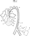
図1は一般に10で示す挿入された先行技術の心補助ポンプの縦方向断面図を例示し、これは外部ポンプ20と、近端部31、遠端部32、吸入弁40、出口弁50およびルーメン51を有するカニューレ30とを含む。好ましくは、カニューレ30は末梢動脈60内、または大腿動脈等の別の好適な動脈の切開部61を介して、経皮で挿入され、大動脈70と大動脈弁140とを介して上流に通され心臓90の左心室80に達する。挿入の方法は技術分野で公知の他の種類の心カニューレの挿入方法と実質的に同様である。カニューレ30の長さは約60cmであり、これはカニューレ30の遠端部が左心室80内に位置付けられたときにカニューレ30の近端部が切開部61に近接して患者の体外に残るのに十分な長さである。これに代えて、カニューレ30は動脈系の別の場所の好適な切開部を介して外科的に挿入してもよい。
【0018】
一旦カニューレ30が定位置に収まると、ポンプ20はカニューレ30内に圧力差を生じさせ、この結果、カニューレ30の遠端部32に位置付けられた吸入弁40が開き、血液が左心室80からルーメン51に流入する。血液がルーメン51を満たす間、出口弁50は閉じられたままである。外部の室(図示せず)が血液で満たされると、ポンプ20は室内に逆の圧力差を生じさせ、この結果、吸入弁40が閉じられ出口弁50が開いて、血液はルーメン51から大動脈70に押出される。
【0019】
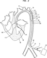
図2は一般に11で示される、患者の大動脈70に挿入されたこの発明の縦方向断面図を例示する。この発明11は大動脈バルーン(IAB)カテーテル100と、出口弁115を有するポンプ室110とを含む。ポンプ室110は近端部99を有する大管室部分111と、遠端部113を有する小管カニューレ部分112とを含む。方向の用語である「遠」は心臓に近い位置を指す。板状(leaflet)吸入弁114または他の好適な吸入弁がポンプ室110の小管カニューレ部112の遠端部113に装着される。IABカテーテル100は一般にバルーン膜101、外管102、先端部103および外部ポンプ20を含む。IABカテーテル100は一般に、必要に応じて挿入用シース71を介して大動脈70内に経皮で挿入され、先端部103が左鎖骨下動脈72にすぐ遠位に位置付けられる。先行技術のIABと同じく、外部ポンプ20がガス等の非血液材料を外管102内で前後に往復させ、これによってバルーン膜101を迅速に膨らませまた萎ませる。バルーン膜101はポンプ室110の大管室部分111内に摺動するように配置されている。大管室部分111の近端部99はIABカテーテル100の外管102に、血液が前記近端部99から流出することのないように、摺動するように装着されている。
【0020】
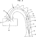
図3および4は患者の大動脈70に挿入されたIABカテーテル100の遠端部とポンプ室110の縦方向断面図を例示する。図3は血液を小管カニューレ部112に押しやる手段を例示している。バルーン膜101は萎んだ状態にあり、この結果ポンプ室110内の圧力は大動脈70内の圧力より低く、好ましくは左心室80のそれに近い。圧力差が板状吸入弁114を開き、血液が小管カニューレ部112の遠端部113に向かって流入することを可能にする。さらに、ポンプ室110の圧力が低いので、出口弁115が閉じ、これによって血液が前記出口弁115から大動脈70に流出するのを防ぐ。図3に例示したように、大動脈弁140は出口弁115と協調して開くことに注目されたい。この例では、心臓90が非開胸式IAB型心室補助装置11と同期してポンプすると仮定している。しかしながら、完全に不全となった左心とのこの発明11の使用も予想される。このような場合、小管カニューレ部112の直径を大きくして全血流を収容できるようにしてもよい。さらに、この発明11で血液が存在する部分は小管カニューレ部112の内側の区域およびバルーン膜101および大管室部分111の間にある環状の区域だけであることに注目されたい。IABカテーテル100はこの発明11の非血液収容部であると考えてもよい。図4は血液がポンプ室110から押出される手段を例示している。バルーン膜101は膨らまされてポンプ室110内の圧力を高める。この結果、吸入弁114が左心室80に再び入ろうとする血液によって強制的に閉じられ、出口弁115が強制的に開けられて、小管カニューレ部112と大管室部分111との中の血液が大動脈70に流入することを可能にする。出口弁115はポンプ室110全体に位置付けられていてもよいことが注目される。この発明11は、わずかな変形により、右心室補助装置としても同様に使用が予想されることに注目されたい。
【0021】
図5は吸入弁114の別の実施例を例示する。吸入弁114はピン117により小管カニューレ部112に回転可能に装着されたディスク116を含む。血液が左心室80に流れ込もうとすると、ディスク116は回転して横の閉じた位置をとり、ストッパ118がある結果そこにとどまり、血液が左心室80に再び入るのを防ぐ。血液が左心室80から流出しようとすると、図6に例示されるように、ディスク116はその縦の開放位置に戻り、血液がポンプ室110に流入することを可能にする。吸入弁および出口弁の他の形態も予測されることに注意されたい。
【0022】
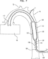
好ましくはIABカテーテル100とポンプ室110とは一連でまたは1ユニットとして経皮で挿入される。IABカテーテルの挿入方法は技術分野で周知である。経皮挿入が可能なポンプ室110の好ましい実施例が図7−8に例示される。ポンプ室110は実際の血液ポンプ動作の間にバルーン膜101の萎む結果として大動脈70に生じる高い圧力に耐えることができなければならず、その一方で挿入の間には大動脈70内を進めることができるように十分柔軟でなければならない。図7はIABカテーテル100のバルーン膜101のまわりに配置された、これらの特性を示す、液で満たされたポンプ室110の縦方向断面を示す。IABカテーテル100は先端部103が左鎖骨下動脈72にすぐ近接するように経皮で挿入される。ポンプ室110は遠端部113と近端部99とを有するポンプ管118、およびポンプ管118に装着された液体供給管119とを有する。ポンプ室110はIABカテーテル100の近端部126まわりに配置され、ポンプ管118の遠端部113が左心室80に入るように、大動脈70の中を進められる。ポンプ管118の近端部99はIABカテーテル100の外管102に、血液が前記近端部99から漏れ出すことができないように、摺動するように装着されている。ルーメン120は液体供給管119の全長にわたって延び、ポンプ管118まわりを螺旋状に、または他の同様の態様で走る。一旦大動脈70内に位置付けられると、ルーメン120は液体で満たされる。液体で満たされたルーメン120はポンプ室110の固さをますので、これはバルーン膜101の萎む間、大動脈70に生ずる圧力に耐えることができる。治療が完了すると、液体はルーメン120からポンプで排出され、ポンプ室110は再び経皮で大動脈から除去できるに十分なほどしなやかで小さくなる。図8は図7で例示された液体で満たされたポンプ室110の斜視図である。液体で満たされた螺旋状ルーメン120の代替物として、さまざまな形状の、液体で満たされた表面セクタまたは液体で満たされたポケットを使用することができる。
【0023】
図9は交差コイル状ワイヤから形成され、市場にある拡張可能ステントと同様の弾性漏れ防止材料または他の好適な材料でカバーされ、引き伸ばされるとその断面直径が減じられる特性を有する、別のポンプ室110を例示する。図9に例示されたようなポンプ室110を組入れた非開胸式IAB型心室補助装置11の挿入は以下のステップを含む。IABカテーテル100はまず大動脈70に挿入される。次に引き伸ばした状態のポンプ室110がIABカテーテル100上を大動脈70内に進められる。IABカテーテル100のバルーン膜101がポンプ室100内に配置されるようにポンプ室110を位置付けると、ポンプ室110が解放されてその小径の引き伸ばされた状態から、大径の引き伸ばされていない状態に拡張される。図9は引き伸ばされていない状態のポンプ室110の平面図である。図10は引き伸ばした状態のポンプ室110の平面図である。ポンプ室110は図2に例示されたポンプ室110と同様の様態でIABカテーテル100に装着される。治療が完了すると、ポンプ室110はその小径の引き伸ばされた状態まで伸ばされ、その後経皮で除去される。ポンプ室110を除去した後に、IABカテーテル100が経皮で除去される。ポンプ室はたとえばコルビタ(Corvita)ステント(FL、マイアミ、コルビタ社製)(Corvita Corp, Miami, FL)等の、市場にある他の拡張可能ステントと同様の様態で患者に挿入され患者から除去される。挿入の別の方法として、IABカテーテル100をポンプ室110の挿入後に挿入してもよい。
【0024】
図11は大動脈70に挿入されたこの発明11の別の実施例の縦方向断面図であり、これはガス管部128を有するカニューレ160と、近端部126と、遠端部113およびダイアフラム127を有するポンプ室110とを含む。ガス管部128の近端部126は外部の非血液ポンプ20に接続されている。ポンプ室110の遠端部は心臓90の左心室80に挿入される。この発明11の第1の実施例と同様に、血流はポンプ室110のみへ制限される。この発明11の血液収容部はポンプ室110のみである。ガス管部128は、ヘリウム等の非血液材料で満たされる。ガス管部128は、基本的にこの発明11の非血液収容部として、図2に示されたようなIABカテーテル100にとって代わるものである。ガス管部128の直径はポンプ室110の直径よりも小さくされ得る。ガス管部128の径を減じることにより、ガス管部128のまわりをより多くの血液が流れることができ、これによって手順の間患者の循環を改良する。
【0025】
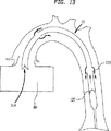
図12に例示されているように、ポンプ20(図11)がガス管部128内の圧力を減じるや否や、隔膜127が血液吸入位置に移動し、この結果出口弁115が閉じ、吸入弁114が開き、血液がポンプ室110に流れ込む。図12は図11に例示された別の実施例の遠端部分の縦方向断面を示し、ダイヤフラム127が血液吸入状態にある。図13に例示されるように、ポンプ20がガス管部128の圧力を増すや否や、隔膜が血液ポンプ位置に移動し、この結果、吸入弁114が閉じ、出口弁115が開き、血液がポンプ室110を出て大動脈70に流れ込む。
【図面の簡単な説明】
【図1】 患者の大動脈に挿入された従来技術の心補助ポンプシステムの縦方向断面図である。
【図2】 患者の大動脈と左心室に挿入された、この発明の非開胸式IAB型心室補助装置の縦方向断面図である。
【図3】 図2に示された挿入された非開胸式IAB型心室補助装置の遠端部分の、バルーン膜が萎んだ状態の縦方向断面図である。
【図4】 図2に示された挿入された非開胸式IAB型心室補助装置の遠端部分の、バルーン膜が膨らまされた状態の縦方向断面図である。
【図5】 非開胸式IAB型心室補助装置の遠端部の、横方向の閉じた状態にある吸入弁の別の実施例の縦方向断面図である。
【図6】 非開胸式IAB型心室補助装置の遠端部の、縦方向に開いた状態にある吸入弁の別の実施例の縦方向断面図である。
【図7】 IABカテーテルバルーン膜のまわりに配置され患者の大動脈と左心室に挿入された液体で満たされたポンプ室の縦方向断面図である。
【図8】 図7に例示された液体で満たされたポンプ室の斜視図である。
【図9】 ポンプ室が引き伸ばされていない大径の状態にある第3の実施例の平面図である。
【図10】 ポンプ室がその伸ばされた小径の状態にある第3の実施例の平面図である。
【図11】 隔膜を有する非開胸式IAB型心室補助装置の別の実施例の縦方向断面図である。
【図12】 隔膜が血液吸入位置にある非開胸式IAB型心室補助装置と大動脈の遠端部分の縦方向断面図である。
【図13】 隔膜が血液ポンプ位置にある非開胸式IAB型心室補助装置と大動脈の遠端部分の縦方向断面図である。[0001]
BACKGROUND OF THE INVENTION
1. FIELD OF THE INVENTION This invention relates generally to devices and systems for increasing cardiac output, and more particularly to aortic heart assist pumps.
[0002]
2. Description of the Prior Art Aortic and intraventricular assist devices are well known in the art. These devices are commonly used to reduce the load on the heart after a stroke or surgery. They are also used to increase blood flow from the left ventricle of the heart to the aorta, for example, when cardiac output is insufficient due to acute or chronic heart disease or interference with normal cardiac function during surgery. be able to.
[0003]
Cardiac assist devices fall into two basic categories. That is, one that includes an external pump chamber that remains outside the body during the entire course of treatment (external) and one that includes an internal pump chamber that remains inside the body (internal). One significant disadvantage of the internal pump chamber is that extensive surgery is required for implantation and removal of the device.
[0004]
Devices with an external pump chamber also have some drawbacks. US Pat. No. 4,014,317, incorporated herein by reference, describes a cardiovascular cannula with an external balloon pump and a cardiac pace electrode. The cannula is inserted percutaneously through the aorta so that its distal end is inside the left ventricle of the heart. During systole, the ventricular contraction forces blood into the cannula while the cannula inlet valve in the left ventricle remains open. Thereafter, during the relaxation phase, blood flows out into the aorta via one or more outlet valves along the cannula downstream of the inlet valve. Functionally, a gas filling chamber similar to an aortic balloon pump (IABP) is connected to the cannula downstream of the outlet valve outside the patient. Balloons are normally inflated during the relaxation phase and deflated during the systolic phase to assist in perfusion of the coronary arteries. The cannula has a long and narrow shape that greatly restricts blood flow, thus limiting the effective pulsatile capacity of the device. Thus, this device has limited utility for increasing blood output in weak or failing hearts.
[0005]
U.S. Pat. No. 4,906,229, also incorporated herein by reference, describes a high frequency intervascular axisymmetric external blood pump. The pump contains a small internal volume in the form of a rigid barrel that can be alternately expanded or reduced by atmospheric or hydraulic pressure acting through a flexible membrane that radially surrounds this volume. it can. This volume has an inlet end and an outlet end and is equipped with a check axial valve at both ends, so that blood can only flow from the heart to the aorta. The pump is connected to the cannula via a check inhalation valve, which is inserted into the left ventricle of the heart via an aortic valve. When the internal volume is expanded, blood flows from the ventricle into the pump. When the volume is subsequently reduced, blood is released from the exit end into the aorta. This pump is designed to operate at a frequency of 600 to 1,000 cycles per minute. Since the pulsatile capacity of the pump is typically only about 3-5 cc, these high cycle rates are required to provide adequate perfusion.
[0006]
A significant disadvantage of the prior art extracorporeal aortic heart assist devices is due to the inherent design constraints of the devices. Prior art extracorporeal aortic heart assist devices pump blood from the left ventricle through the cannula to the downstream portion of the artery. It is desirable to make the inner diameter of the cannula as large as possible so that the blood flow through the cannula can be as large as possible. However, it is also desirable to make the outer diameter of the cannula as small as possible so as to facilitate insertion into the artery and not substantially reduce blood flow in the artery surrounding the cannula. As a result of these competing design goals, the cannula is typically designed to be sized to accommodate only 20-40 cc of blood per heart cycle. However, the average patient requires about 80-100 cc of blood per heart cycle for adequate blood flow support.
[0007]
Apart from the internal / external pump chamber distinction, cardiac assist devices are also divided into categories by their pump drive. That is, it is a continuous type or a pulsating type. In the Hemopump Cardiac Assist System, which is distributed by the Johnson & Johnson Interventional Systems, a cannula containing a special small rotor pump mechanism is inserted into the aorta. The pump is driven by an extracorporeal drive unit that pumps blood continuously from the aorta to the rest of the arterial system, thereby supplementing the heart's natural output rate to some extent. This type of system is also described in US Pat. No. 5,092,844, which is hereby incorporated by reference. The disadvantage of this system is that the outer diameter of the pump, and therefore the pump output, is limited due to the need for insertion through the femoral artery. A further disadvantage of this system, and generally the continuous flow device, relates to the belief that the pulsating pump provides effective long-term support compared to the continuous flow device because the pulsating device is the heart of the heart. This is because the approximation is closer to the natural pumping action.
[0008]
One of the best known and most widely used aortic pump systems is the aortic balloon pump (IABP), which has an inflatable balloon at its distal end that passes through the artery to the aorta. Inserted. The balloon is alternately inflated and deflated by an external pump drive, thereby alternately increasing and decreasing the blood pressure in the aorta in reverse phase with the heart beat, helping the left ventricle to drive blood into the arterial system . An aortic balloon (IAB) catheter is a popular cardiac assist device. This is because it can be inserted percutaneously, thus avoiding major surgery associated with implantation and removal of the internal ventricular assist device. However, IABP provides only a limited increase in power without the natural assistance of the heart and is not appropriate to overcome serious heart failure.
U.S. Pat. No. 4,906,229 issued to Wampler discloses a high frequency intervascular blood pump for temporary cardiac assistance. The pump inlet is connected to a cannula, which is inserted through the aortic valve into the ventricular cavity, which has an inhalation opening at its distal end. The pump itself forms a hard barrel and its internal volume can be alternately reduced or increased by a flexible membrane controlled by pressure or water pressure from an extracorporeal position through a percutaneously inserted lumen.
GB-A — 1526099 discloses a surgically implantable semi-biological internal circuit pump device that includes a balloon catheter placed in a rigid pump chamber.
[0009]
While these devices may be suitable for the particular purpose adopted or for general use, they will not be as well suited for the purposes of the invention disclosed below.
[0010]
SUMMARY OF THE INVENTION
Accordingly, it is an object of the present invention to produce a cardiac assist device that can overcome heart failure by providing sufficient blood flow support.
[0011]
Another object of the present invention is to produce a cardiac assist device that can be inserted percutaneously or with limited incision procedures and thus does not require extensive thoracic surgery for implantation and removal.
[0012]
A further object of the present invention is to produce a cardiac assist device that produces pulsatile blood flow that more closely approximates the natural pumping action of the heart.
[0013]
A further object of the present invention is to produce a cardiac assist device that does not substantially reduce blood flow in the occupied artery.
[0014]
The present invention is a non-thoracotomy aortic balloon catheter type ventricular assist device that includes an aortic balloon (IAB) catheter and a pump chamber having a small diameter portion and a larger diameter portion at a proximal end. An IAB catheter balloon membrane is placed on the large diameter portion. The entire device is inserted percutaneously into the patient's aorta so that the tip of the IAB catheter is just distal to the left subclavian artery and the distal end of the small diameter is in the left ventricle. The small diameter portion has a suction valve at its distal end that acts as a check valve that allows blood to flow into the lumen of the pump chamber but not out of it. The pump chamber has one or more outlet valves. When the balloon membrane is deflated, the pressure in the pump chamber drops below that in the left ventricle, resulting in blood flowing into the pump chamber. When the balloon membrane is inflated, the pressure in the pump chamber increases, forcing the suction valve to close and pushes blood through the outlet valve to the aorta. The pump chamber becomes substantially rigid after insertion and withstands arterial blood pressure.
[0015]
To the accomplishment of the foregoing and related ends, the invention may be practiced in the form illustrated in the accompanying drawings. However, it should be noted that the drawings are for illustration only. Variations are considered part of the invention and the invention is limited only by the scope of the claims.
[0016]
In the drawings, similar elements are designated with similar reference numerals. A brief description of the drawings will be given later.
[0017]
Detailed Description of the Preferred Embodiment
FIG. 1 illustrates a longitudinal cross-sectional view of an inserted prior art cardiac assist pump, generally indicated at 10, which includes an
[0018]
Once the
[0019]
FIG. 2 illustrates a longitudinal cross-sectional view of the present invention inserted into the patient's
[0020]
FIGS. 3 and 4 illustrate longitudinal cross-sectional views of the distal end of the
[0021]
FIG. 5 illustrates another embodiment of the
[0022]
Preferably, the
[0023]
FIG. 9 shows another pump formed of crossed coiled wires and covered with an elastic leak-proof material or other suitable material similar to an expandable stent on the market, and has the property of reducing its cross-sectional diameter when stretched The
[0024]
FIG. 11 is a longitudinal cross-sectional view of another embodiment of the
[0025]
As illustrated in FIG. 12, as soon as the pump 20 (FIG. 11) reduces the pressure in the gas pipe section 128, the
[Brief description of the drawings]
FIG. 1 is a longitudinal cross-sectional view of a prior art cardiac assist pump system inserted into a patient's aorta.
FIG. 2 is a longitudinal cross-sectional view of a non-thoracotomy type IAB ventricular assist device of the present invention inserted into a patient's aorta and left ventricle.
3 is a longitudinal cross-sectional view of the distal end portion of the inserted non-thoracotomy type IAB ventricular assist device shown in FIG. 2 with the balloon membrane deflated. FIG.
4 is a longitudinal cross-sectional view of the distal end of the inserted non-thoracotomy type IAB ventricular assist device shown in FIG. 2 with the balloon membrane inflated. FIG.
FIG. 5 is a longitudinal cross-sectional view of another embodiment of the inhalation valve in the laterally closed state at the distal end of the non-thoracotomy type IAB ventricular assist device.
FIG. 6 is a longitudinal cross-sectional view of another embodiment of the inhalation valve in the longitudinally open state at the distal end of the non-thoracotomy type IAB ventricular assist device.
FIG. 7 is a longitudinal cross-sectional view of a pump chamber filled with fluid placed around an IAB catheter balloon membrane and inserted into the patient's aorta and left ventricle.
8 is a perspective view of a pump chamber filled with liquid illustrated in FIG. 7;
FIG. 9 is a plan view of a third embodiment in which the pump chamber is in a large diameter state where the pump chamber is not stretched.
FIG. 10 is a plan view of a third embodiment in which the pump chamber is in the extended small diameter state.
FIG. 11 is a longitudinal cross-sectional view of another embodiment of a non-thoracotomy type IAB ventricular assist device having a septum.
FIG. 12 is a longitudinal sectional view of a non-thoracotomy type IAB type ventricular assist device with a diaphragm in a blood inhalation position and a distal end portion of an aorta.
FIG. 13 is a longitudinal cross-sectional view of a non-thoracotomy type IAB ventricular assist device with the diaphragm in the blood pump position and the distal end portion of the aorta.
Claims (7)
(a) 血液収容部分を含み、血液収容部分は内部の第1ルーメンを取り囲みそれを規定する外径を有するポンプ室を含み、前記ポンプ室は遠端部、近端部、少なくとも1個の出口弁および少なくとも1個の吸入弁を有し、ポンプ室は被験者の血管を通って遠端部が前記被験者の心臓の心室内に位置付けられ、血液がポンプ室の遠端部に近接した吸入弁を介して心室から第1ルーメンに入り、血液が吸入弁に近接した出口弁を介して第1ルーメンから出るように挿入され、血液収容部は被験者の体内に完全に含まれ;さらに
(b) 非血液収容部を含み、非血液収容部は外径を有しさらに近端部が非血液収容部の容積を変更することにより血液収容部の血液の容積を変更する手段に接続されており、非血液収容部の容積が減じられるとそれに対応して心室から吸入弁を通って第1ルーメンへの血流により血液収容部の容積が増加し、非血液収容部の容積が増大するとそれに対応して出口弁から被験者の血管への血流により血液収容部の容積が減じられ、
血液収容部の血液の容積を変更するための手段は非血液収容部の近端部に装着された非血液ポンプと、血液収容部と非血液収容部とを分離しかつ血液吸入位置と血液ポンプ位置との間で移動する柔軟な隔膜とを含み、非血液ポンプは非血液収容部内の圧力を増加させることにより非血液収容部の容積を増加させ、非血液収容部の圧力を減じることにより非血液収容部の容積を減じ、非血液収容部の圧力が血液収容部の圧力より高くされると隔膜は血液ポンプ位置に移動して血液が血液収容部から出口弁を介して血管に流出するようにさせ、非血液収容部の圧力が血液収容部の圧力より低くされると隔膜は血液吸入位置に移動して血液を吸入弁を介して血液収容部に入れる、装置。A device for a blood pump,
Include (a) blood receiving portion, the blood receiving portion comprises a pump chamber having an outer diameter defining it surrounds the first lumen of the internal, the pump chamber distal end, a proximal end, at least one out of has a mouth valve and at least one intake Iriben, pump chamber distal end through a blood vessel of the subject is positioned in a chamber of the heart of the subject, the blood is close to the distal end portion of the pump chamber inlet enters the first lumen from the ventricle through the valve, blood is inserted so as to exit the first lumen via the outlet valve close to the inlet valve, the blood containing portion is contained entirely within the body of a subject; and (b ) a non-blood containing portion, non-blood containing portion is connected to the means for changing the blood volume of the blood containing portion by a proximal end further has an outer diameter changes the volume of non-blood containing portion , the volume of non-blood containing portion is reduced it pairs And the volume of the blood containing portion is increased by blood flow to the first lumen through the intake valve from the ventricle, the blood flow from the non-blood containing portion outlet valve correspondingly the volume is increased to the subject of the vessel volume of blood containing portion is Ji reduced by,
Means for changing the volume of blood in the blood storage part are a non-blood pump mounted at a near end of the non-blood storage part, a blood storage part and a non-blood storage part, and a blood suction position and a blood pump. A non-blood pump that increases the volume of the non-blood container by increasing the pressure in the non-blood container and reduces the pressure of the non-blood container by reducing the pressure in the non-blood container. When the volume of the blood storage part is reduced and the pressure of the non-blood storage part is made higher than the pressure of the blood storage part, the diaphragm moves to the blood pump position so that blood flows out from the blood storage part to the blood vessel via the outlet valve. And when the pressure in the non-blood containing part is made lower than the pressure in the blood containing part, the diaphragm moves to the blood inhaling position and enters the blood into the blood containing part via the suction valve .
ポンプ室が、引き伸ばされたときにその断面径が減少し引き伸ばしから解放されたときにその先のより大きな断面径に戻る特性を有し、
ポンプ室が交差コイル状ワイヤからなる、血液ポンプ用装置。
る、血液ポンプ用装置。A blood pump device comprising an aortic balloon catheter having a balloon membrane and a pump chamber having a distal end, a large lumen portion and a communicating small cannula portion, wherein the large lumen portion is a proximal end and a proximal end thereof A balloon membrane having an opening on the section and a larger outer diameter than the small tube cannula section, the deflated balloon membrane can pass through and fit through the opening at the proximal end of the large tube chamber portion, and the balloon membrane Is arranged to slide into the large tube chamber portion, and the pump chamber has at least one suction valve near its distal end and at least one outlet valve closer to the balloon membrane than the suction valve. And when the balloon membrane is deflated, blood enters the pump chamber via the suction valve and the outlet valve is closed, and when the balloon membrane is inflated, the suction valve is closed and the blood in the pump chamber is extruded through the outlet valve, and the pump Because the room is inserted into the patient Monodea is,
The pump chamber has the property of reducing its cross-sectional diameter when stretched and returning to a larger cross-sectional diameter beyond that when released from stretching;
A device for blood pump , wherein the pump chamber is made of crossed coiled wires .
Blood pump device.
ポンプ室が硬化材料を保持する硬化手段を含み、
硬化材料が液体であり、
硬化手段が硬化材料を受け入れることのできる第2ルーメンと硬化材料を供給するための供給管とを含み、
第2ルーメンがポンプ室のまわりを螺旋状に走る、血液ポンプ用装置。 A blood pump device comprising an aortic balloon catheter having a balloon membrane and a pump chamber having a distal end, a large lumen portion and a communicating small cannula portion , wherein the large lumen portion is a proximal end and a proximal end thereof A balloon membrane having an opening on the section and a larger outer diameter than the small tube cannula section, the deflated balloon membrane can pass through and fit through the opening at the proximal end of the large tube chamber portion, and the balloon membrane Is arranged to slide into the large tube chamber portion, and the pump chamber has at least one suction valve near its distal end and at least one outlet valve closer to the balloon membrane than the suction valve. And when the balloon membrane is deflated, blood enters the pump chamber via the suction valve and the outlet valve is closed, and when the balloon membrane is inflated, the suction valve is closed and the blood in the pump chamber is extruded through the outlet valve, and the pump Because the room is inserted into the patient It is those,
The curing means for the pump chamber to hold the curing material seen including,
The curable material is liquid,
The curing means includes a second lumen capable of receiving the curable material and a supply tube for supplying the curable material;
A blood pump device in which the second lumen runs spirally around the pump chamber .
Applications Claiming Priority (3)
| Application Number | Priority Date | Filing Date | Title |
|---|---|---|---|
| US09/052,491 US5928132A (en) | 1998-03-31 | 1998-03-31 | Closed chest intra-aortic balloon based ventricular assist device |
| US09/052,491 | 1998-03-31 | ||
| PCT/US1999/005172 WO1999049911A1 (en) | 1998-03-31 | 1999-03-10 | Closed chest intra-aortic balloon based ventricular assist device |
Publications (3)
| Publication Number | Publication Date |
|---|---|
| JP2002509769A JP2002509769A (en) | 2002-04-02 |
| JP2002509769A5 JP2002509769A5 (en) | 2005-12-22 |
| JP4022372B2 true JP4022372B2 (en) | 2007-12-19 |
Family
ID=21977949
Family Applications (1)
| Application Number | Title | Priority Date | Filing Date |
|---|---|---|---|
| JP2000540873A Expired - Fee Related JP4022372B2 (en) | 1998-03-31 | 1999-03-10 | Non-thoracotomy aortic balloon type ventricular assist device |
Country Status (8)
| Country | Link |
|---|---|
| US (1) | US5928132A (en) |
| EP (1) | EP1066066B1 (en) |
| JP (1) | JP4022372B2 (en) |
| AT (1) | ATE271398T1 (en) |
| AU (1) | AU3074599A (en) |
| DE (1) | DE69918816T2 (en) |
| ES (1) | ES2224619T3 (en) |
| WO (1) | WO1999049911A1 (en) |
Cited By (4)
| Publication number | Priority date | Publication date | Assignee | Title |
|---|---|---|---|---|
| US10722631B2 (en) | 2018-02-01 | 2020-07-28 | Shifamed Holdings, Llc | Intravascular blood pumps and methods of use and manufacture |
| US11185677B2 (en) | 2017-06-07 | 2021-11-30 | Shifamed Holdings, Llc | Intravascular fluid movement devices, systems, and methods of use |
| US11511103B2 (en) | 2017-11-13 | 2022-11-29 | Shifamed Holdings, Llc | Intravascular fluid movement devices, systems, and methods of use |
| US11964145B2 (en) | 2019-07-12 | 2024-04-23 | Shifamed Holdings, Llc | Intravascular blood pumps and methods of manufacture and use |
Families Citing this family (55)
| Publication number | Priority date | Publication date | Assignee | Title |
|---|---|---|---|---|
| US7780628B1 (en) * | 1999-01-11 | 2010-08-24 | Angiodynamics, Inc. | Apparatus and methods for treating congestive heart disease |
| US7481803B2 (en) * | 2000-11-28 | 2009-01-27 | Flowmedica, Inc. | Intra-aortic renal drug delivery catheter |
| US6749598B1 (en) | 1999-01-11 | 2004-06-15 | Flowmedica, Inc. | Apparatus and methods for treating congestive heart disease |
| US7329236B2 (en) * | 1999-01-11 | 2008-02-12 | Flowmedica, Inc. | Intra-aortic renal drug delivery catheter |
| US7022100B1 (en) | 1999-09-03 | 2006-04-04 | A-Med Systems, Inc. | Guidable intravascular blood pump and related methods |
| US7150737B2 (en) * | 2001-07-13 | 2006-12-19 | Sci/Med Life Systems, Inc. | Methods and apparatuses for navigating the subarachnoid space |
| US6669624B2 (en) | 2002-03-26 | 2003-12-30 | O. Howard Frazier | Temporary heart-assist system |
| JP2006513809A (en) * | 2002-09-20 | 2006-04-27 | フローメディカ,インコーポレイテッド | Apparatus and method for inserting an intra-aortic catheter through a delivery sheath |
| EP1539291A4 (en) | 2002-09-20 | 2010-03-10 | Flowmedica Inc | Method and apparatus for selective material delivery via an intra-renal catheter |
| US7993325B2 (en) | 2002-09-20 | 2011-08-09 | Angio Dynamics, Inc. | Renal infusion systems and methods |
| US20050197624A1 (en) | 2004-03-04 | 2005-09-08 | Flowmedica, Inc. | Sheath for use in peripheral interventions |
| AU2003294226A1 (en) | 2002-09-20 | 2004-04-23 | Flowmedica, Inc. | Method and apparatus for intra aortic substance delivery to a branch vessel |
| US7063679B2 (en) * | 2002-09-20 | 2006-06-20 | Flowmedica, Inc. | Intra-aortic renal delivery catheter |
| US7468050B1 (en) | 2002-12-27 | 2008-12-23 | L. Vad Technology, Inc. | Long term ambulatory intra-aortic balloon pump |
| US8540618B2 (en) * | 2003-01-31 | 2013-09-24 | L-Vad Technology, Inc. | Stable aortic blood pump implant |
| US8721515B2 (en) * | 2003-01-31 | 2014-05-13 | L-Vad Technology, Inc. | Rigid body aortic blood pump implant |
| JP2006526464A (en) | 2003-06-05 | 2006-11-24 | フローメディカ,インコーポレイテッド | System and method for performing bilateral intervention or diagnosis in a branched body lumen |
| US7374531B1 (en) | 2003-06-11 | 2008-05-20 | L. Vad Technology, Inc. | Long term ambulatory intra-aortic balloon pump with three dimensional tortuous shape |
| DE10336902C5 (en) | 2003-08-08 | 2019-04-25 | Abiomed Europe Gmbh | Intracardiac pumping device |
| US7066874B2 (en) * | 2004-01-06 | 2006-06-27 | Bay Innovation Group, Llc | Devices and methods for blood flow assistance |
| US7811221B2 (en) * | 2004-02-10 | 2010-10-12 | Yossi Gross | Extracardiac blood flow amplification device |
| US7172551B2 (en) * | 2004-04-12 | 2007-02-06 | Scimed Life Systems, Inc. | Cyclical pressure coronary assist pump |
| US20060069323A1 (en) * | 2004-09-24 | 2006-03-30 | Flowmedica, Inc. | Systems and methods for bi-lateral guidewire cannulation of branched body lumens |
| US7544160B2 (en) * | 2005-02-10 | 2009-06-09 | Yossi Gross | Extracardiac blood flow amplification device |
| US7479102B2 (en) * | 2005-02-28 | 2009-01-20 | Robert Jarvik | Minimally invasive transvalvular ventricular assist device |
| CN101472627B (en) * | 2006-01-30 | 2013-05-08 | 国立成功大学 | Dual-pulsation bi-ventricular assist device |
| US8196580B2 (en) * | 2006-05-11 | 2012-06-12 | Yossi Gross | Implantable respiration therapy device |
| US7771401B2 (en) | 2006-06-08 | 2010-08-10 | Angiodynamics, Inc. | Selective renal cannulation and infusion systems and methods |
| US7914436B1 (en) | 2006-06-12 | 2011-03-29 | Abiomed, Inc. | Method and apparatus for pumping blood |
| DE102007012817A1 (en) * | 2007-03-16 | 2008-09-18 | Mwf Consult Ltd. | Device for supporting the heart and the circulation |
| US8439859B2 (en) | 2007-10-08 | 2013-05-14 | Ais Gmbh Aachen Innovative Solutions | Catheter device |
| US20090259089A1 (en) * | 2008-04-10 | 2009-10-15 | Daniel Gelbart | Expandable catheter for delivery of fluids |
| US20090270815A1 (en) * | 2008-04-29 | 2009-10-29 | Infraredx, Inc. | Catheter Priming System |
| US8235885B2 (en) | 2008-05-05 | 2012-08-07 | Coherex Medical, Inc. | Ventricular assist device and related methods |
| US8540616B2 (en) | 2008-05-05 | 2013-09-24 | Coherex Medical, Inc. | Ventricular assist device and related methods |
| CN102202718B (en) * | 2008-09-05 | 2014-09-03 | 心脏聚合体有限公司 | Apparatus and method for capsule formation in tissue |
| US8523756B2 (en) * | 2008-12-31 | 2013-09-03 | National Cheng Kung University | Cardiac compression system |
| EP2298371A1 (en) * | 2009-09-22 | 2011-03-23 | ECP Entwicklungsgesellschaft mbH | Function element, in particular fluid pump with a housing and a transport element |
| JP2014501554A (en) * | 2010-11-05 | 2014-01-23 | タフツ メディカル センター インコーポレイテッド | Cannula with bifurcated tip for cardiac assist device |
| EP2607712B1 (en) * | 2011-12-22 | 2016-07-13 | ECP Entwicklungsgesellschaft mbH | Pump housing with an interior for holding a pump rotor |
| DE102014003153B4 (en) * | 2014-03-03 | 2015-10-08 | Novapump Gmbh | Catheter for directionally directing a fluid, in particular a body fluid |
| US11583670B2 (en) | 2014-03-03 | 2023-02-21 | Novapump Gmbh | Catheter for the directional conveyance of a fluid, particularly a body fluid |
| US9981078B2 (en) | 2014-09-15 | 2018-05-29 | Lijun Jin | Left ventricular assist device |
| CN104174078B (en) * | 2014-09-15 | 2016-09-21 | 靳立军 | A kind of left ventricular assist device |
| DE102015216050A1 (en) * | 2015-08-21 | 2017-02-23 | Robert Bosch Gmbh | Pump for a fluid and cardiac support system |
| CA3039285A1 (en) | 2016-10-25 | 2018-05-03 | Magenta Medical Ltd. | Ventricular assist device |
| US11351355B2 (en) * | 2017-10-19 | 2022-06-07 | Datascope Corporation | Devices for pumping blood, related systems, and related methods |
| CN115089870A (en) | 2018-01-10 | 2022-09-23 | 马真塔医药有限公司 | Ventricular assist device |
| US10905808B2 (en) | 2018-01-10 | 2021-02-02 | Magenta Medical Ltd. | Drive cable for use with a blood pump |
| CN115137967A (en) | 2019-01-24 | 2022-10-04 | 马真塔医药有限公司 | Ventricular assist device |
| US10888644B2 (en) | 2019-02-06 | 2021-01-12 | inQB8 Medical Technologies, LLC | Intra-cardiac left atrial and dual support systems |
| US10987456B2 (en) * | 2019-09-23 | 2021-04-27 | Synecor Llc | Devices for use in extracting percutaneous ventricular assist devices |
| CN110575577B (en) * | 2019-09-25 | 2022-04-05 | 周诚 | Novel auxiliary device for treating Fontan circulatory failure |
| CN112870547A (en) * | 2021-02-07 | 2021-06-01 | 华中科技大学同济医学院附属协和医院 | Serial axial flow pump auxiliary device for treating Fontan postoperative circulation failure and using method thereof |
| CN113018543B (en) * | 2021-03-02 | 2021-10-08 | 江苏赛腾医疗科技有限公司 | Diversion control system |
Family Cites Families (12)
| Publication number | Priority date | Publication date | Assignee | Title |
|---|---|---|---|---|
| US4014317A (en) * | 1972-02-18 | 1977-03-29 | The United States Of America As Represented By The Department Of Health, Education And Welfare | Multipurpose cardiocirculatory assist cannula and methods of use thereof |
| US3974825A (en) * | 1975-10-01 | 1976-08-17 | Baylor College Of Medicine | Remote electrical monitoring of gas activated blood pumps |
| US4015590A (en) * | 1976-04-12 | 1977-04-05 | Baylor College Of Medicine | Balloon activated blood pump |
| GB1526099A (en) * | 1976-11-19 | 1978-09-27 | Bodnar E | Semi-biological internal circuit pumping device |
| US4861330A (en) * | 1987-03-12 | 1989-08-29 | Gene Voss | Cardiac assist device and method |
| US4906229A (en) * | 1988-05-03 | 1990-03-06 | Nimbus Medical, Inc. | High-frequency transvalvular axisymmetric blood pump |
| US5092844A (en) * | 1990-04-10 | 1992-03-03 | Mayo Foundation For Medical Education And Research | Intracatheter perfusion pump apparatus and method |
| ES2020787A6 (en) * | 1990-07-20 | 1991-09-16 | Figuera Aymerich Diego | Intra-ventricular expansible assist pump |
| US5332403A (en) * | 1992-08-17 | 1994-07-26 | Jack Kolff | LVAD with t-shape and unidirectional valve |
| FR2733143B1 (en) * | 1995-04-21 | 1997-11-07 | Nycomed Lab Sa | DEVICE FOR TEMPORARILY SHUTTERING A BODY CHANNEL, ESPECIALLY USEFUL FOR PRESSURE HEART ASSISTANCE |
| IL114517A0 (en) * | 1995-07-10 | 1995-11-27 | R D C Rafael Dev Corp Ltd | Heart assist system |
| US5820542A (en) * | 1996-10-31 | 1998-10-13 | Momentum Medical, Inc. | Modified circulatory assist device |
-
1998
- 1998-03-31 US US09/052,491 patent/US5928132A/en not_active Expired - Lifetime
-
1999
- 1999-03-10 EP EP19990912354 patent/EP1066066B1/en not_active Expired - Lifetime
- 1999-03-10 AU AU30745/99A patent/AU3074599A/en not_active Abandoned
- 1999-03-10 AT AT99912354T patent/ATE271398T1/en not_active IP Right Cessation
- 1999-03-10 DE DE69918816T patent/DE69918816T2/en not_active Expired - Lifetime
- 1999-03-10 WO PCT/US1999/005172 patent/WO1999049911A1/en active IP Right Grant
- 1999-03-10 JP JP2000540873A patent/JP4022372B2/en not_active Expired - Fee Related
- 1999-03-10 ES ES99912354T patent/ES2224619T3/en not_active Expired - Lifetime
Cited By (5)
| Publication number | Priority date | Publication date | Assignee | Title |
|---|---|---|---|---|
| US11185677B2 (en) | 2017-06-07 | 2021-11-30 | Shifamed Holdings, Llc | Intravascular fluid movement devices, systems, and methods of use |
| US11511103B2 (en) | 2017-11-13 | 2022-11-29 | Shifamed Holdings, Llc | Intravascular fluid movement devices, systems, and methods of use |
| US10722631B2 (en) | 2018-02-01 | 2020-07-28 | Shifamed Holdings, Llc | Intravascular blood pumps and methods of use and manufacture |
| US11229784B2 (en) | 2018-02-01 | 2022-01-25 | Shifamed Holdings, Llc | Intravascular blood pumps and methods of use and manufacture |
| US11964145B2 (en) | 2019-07-12 | 2024-04-23 | Shifamed Holdings, Llc | Intravascular blood pumps and methods of manufacture and use |
Also Published As
| Publication number | Publication date |
|---|---|
| WO1999049911A1 (en) | 1999-10-07 |
| AU3074599A (en) | 1999-10-18 |
| EP1066066B1 (en) | 2004-07-21 |
| US5928132A (en) | 1999-07-27 |
| ATE271398T1 (en) | 2004-08-15 |
| DE69918816T2 (en) | 2005-08-18 |
| EP1066066A1 (en) | 2001-01-10 |
| ES2224619T3 (en) | 2005-03-01 |
| JP2002509769A (en) | 2002-04-02 |
| DE69918816D1 (en) | 2004-08-26 |
Similar Documents
| Publication | Publication Date | Title |
|---|---|---|
| JP4022372B2 (en) | Non-thoracotomy aortic balloon type ventricular assist device | |
| US6299575B1 (en) | Implantable heart assist system | |
| US8480555B2 (en) | Method and apparatus for pumping blood | |
| US4592340A (en) | Artificial catheter means | |
| JP2005500862A (en) | Apparatus and method for treating congestive heart disease | |
| EP1045708A1 (en) | Heart assist system with apex cannula pump | |
| EP1009466A1 (en) | Valve for a heart assist device | |
| US6228018B1 (en) | Removable left ventricular assist device with an aortic support apparatus | |
| JP2003000700A (en) | Circulation assist method using balloon of iabp system and device thereof and bloodstream control valve | |
| US20220280768A1 (en) | Cannula for Endovascular Blood Circuit Support, Corresponding Assembly, Method and Cannula System | |
| CN116099120A (en) | Combined auxiliary treatment system for heart and kidney | |
| WO2021032801A1 (en) | Cannula system comprising two cannulas and corresponding method | |
| MXPA00003173A (en) | Implantable heart assist system |
Legal Events
| Date | Code | Title | Description |
|---|---|---|---|
| A521 | Request for written amendment filed |
Free format text: JAPANESE INTERMEDIATE CODE: A523 Effective date: 20050303 |
|
| A621 | Written request for application examination |
Free format text: JAPANESE INTERMEDIATE CODE: A621 Effective date: 20050303 |
|
| A977 | Report on retrieval |
Free format text: JAPANESE INTERMEDIATE CODE: A971007 Effective date: 20070515 |
|
| A131 | Notification of reasons for refusal |
Free format text: JAPANESE INTERMEDIATE CODE: A131 Effective date: 20070522 |
|
| A521 | Request for written amendment filed |
Free format text: JAPANESE INTERMEDIATE CODE: A523 Effective date: 20070725 |
|
| TRDD | Decision of grant or rejection written | ||
| A01 | Written decision to grant a patent or to grant a registration (utility model) |
Free format text: JAPANESE INTERMEDIATE CODE: A01 Effective date: 20070904 |
|
| A61 | First payment of annual fees (during grant procedure) |
Free format text: JAPANESE INTERMEDIATE CODE: A61 Effective date: 20071001 |
|
| FPAY | Renewal fee payment (event date is renewal date of database) |
Free format text: PAYMENT UNTIL: 20101005 Year of fee payment: 3 |
|
| R150 | Certificate of patent or registration of utility model |
Free format text: JAPANESE INTERMEDIATE CODE: R150 |
|
| FPAY | Renewal fee payment (event date is renewal date of database) |
Free format text: PAYMENT UNTIL: 20111005 Year of fee payment: 4 |
|
| FPAY | Renewal fee payment (event date is renewal date of database) |
Free format text: PAYMENT UNTIL: 20121005 Year of fee payment: 5 |
|
| FPAY | Renewal fee payment (event date is renewal date of database) |
Free format text: PAYMENT UNTIL: 20131005 Year of fee payment: 6 |
|
| R250 | Receipt of annual fees |
Free format text: JAPANESE INTERMEDIATE CODE: R250 |
|
| R250 | Receipt of annual fees |
Free format text: JAPANESE INTERMEDIATE CODE: R250 |
|
| R250 | Receipt of annual fees |
Free format text: JAPANESE INTERMEDIATE CODE: R250 |
|
| R250 | Receipt of annual fees |
Free format text: JAPANESE INTERMEDIATE CODE: R250 |
|
| R250 | Receipt of annual fees |
Free format text: JAPANESE INTERMEDIATE CODE: R250 |
|
| LAPS | Cancellation because of no payment of annual fees |