JP4020434B2 - Apparatus and method for selective optical measurement - Google Patents
Apparatus and method for selective optical measurement Download PDFInfo
- Publication number
- JP4020434B2 JP4020434B2 JP52581298A JP52581298A JP4020434B2 JP 4020434 B2 JP4020434 B2 JP 4020434B2 JP 52581298 A JP52581298 A JP 52581298A JP 52581298 A JP52581298 A JP 52581298A JP 4020434 B2 JP4020434 B2 JP 4020434B2
- Authority
- JP
- Japan
- Prior art keywords
- diffraction grating
- diffraction
- detector
- sample
- grating
- Prior art date
- Legal status (The legal status is an assumption and is not a legal conclusion. Google has not performed a legal analysis and makes no representation as to the accuracy of the status listed.)
- Expired - Fee Related
Links
Images


Classifications
-
- G—PHYSICS
- G01—MEASURING; TESTING
- G01B—MEASURING LENGTH, THICKNESS OR SIMILAR LINEAR DIMENSIONS; MEASURING ANGLES; MEASURING AREAS; MEASURING IRREGULARITIES OF SURFACES OR CONTOURS
- G01B9/00—Measuring instruments characterised by the use of optical techniques
- G01B9/02—Interferometers
- G01B9/02001—Interferometers characterised by controlling or generating intrinsic radiation properties
- G01B9/02007—Two or more frequencies or sources used for interferometric measurement
-
- A—HUMAN NECESSITIES
- A61—MEDICAL OR VETERINARY SCIENCE; HYGIENE
- A61B—DIAGNOSIS; SURGERY; IDENTIFICATION
- A61B5/00—Measuring for diagnostic purposes; Identification of persons
- A61B5/0059—Measuring for diagnostic purposes; Identification of persons using light, e.g. diagnosis by transillumination, diascopy, fluorescence
- A61B5/0062—Arrangements for scanning
- A61B5/0066—Optical coherence imaging
-
- A—HUMAN NECESSITIES
- A61—MEDICAL OR VETERINARY SCIENCE; HYGIENE
- A61B—DIAGNOSIS; SURGERY; IDENTIFICATION
- A61B5/00—Measuring for diagnostic purposes; Identification of persons
- A61B5/0059—Measuring for diagnostic purposes; Identification of persons using light, e.g. diagnosis by transillumination, diascopy, fluorescence
- A61B5/0062—Arrangements for scanning
- A61B5/0068—Confocal scanning
-
- G—PHYSICS
- G01—MEASURING; TESTING
- G01B—MEASURING LENGTH, THICKNESS OR SIMILAR LINEAR DIMENSIONS; MEASURING ANGLES; MEASURING AREAS; MEASURING IRREGULARITIES OF SURFACES OR CONTOURS
- G01B11/00—Measuring arrangements characterised by the use of optical techniques
-
- G—PHYSICS
- G01—MEASURING; TESTING
- G01B—MEASURING LENGTH, THICKNESS OR SIMILAR LINEAR DIMENSIONS; MEASURING ANGLES; MEASURING AREAS; MEASURING IRREGULARITIES OF SURFACES OR CONTOURS
- G01B11/00—Measuring arrangements characterised by the use of optical techniques
- G01B11/30—Measuring arrangements characterised by the use of optical techniques for measuring roughness or irregularity of surfaces
- G01B11/303—Measuring arrangements characterised by the use of optical techniques for measuring roughness or irregularity of surfaces using photoelectric detection means
-
- G—PHYSICS
- G01—MEASURING; TESTING
- G01B—MEASURING LENGTH, THICKNESS OR SIMILAR LINEAR DIMENSIONS; MEASURING ANGLES; MEASURING AREAS; MEASURING IRREGULARITIES OF SURFACES OR CONTOURS
- G01B9/00—Measuring instruments characterised by the use of optical techniques
- G01B9/02—Interferometers
- G01B9/02001—Interferometers characterised by controlling or generating intrinsic radiation properties
- G01B9/02002—Interferometers characterised by controlling or generating intrinsic radiation properties using two or more frequencies
-
- G—PHYSICS
- G01—MEASURING; TESTING
- G01B—MEASURING LENGTH, THICKNESS OR SIMILAR LINEAR DIMENSIONS; MEASURING ANGLES; MEASURING AREAS; MEASURING IRREGULARITIES OF SURFACES OR CONTOURS
- G01B9/00—Measuring instruments characterised by the use of optical techniques
- G01B9/02—Interferometers
- G01B9/02001—Interferometers characterised by controlling or generating intrinsic radiation properties
- G01B9/02012—Interferometers characterised by controlling or generating intrinsic radiation properties using temporal intensity variation
- G01B9/02014—Interferometers characterised by controlling or generating intrinsic radiation properties using temporal intensity variation by using pulsed light
-
- G—PHYSICS
- G01—MEASURING; TESTING
- G01B—MEASURING LENGTH, THICKNESS OR SIMILAR LINEAR DIMENSIONS; MEASURING ANGLES; MEASURING AREAS; MEASURING IRREGULARITIES OF SURFACES OR CONTOURS
- G01B9/00—Measuring instruments characterised by the use of optical techniques
- G01B9/02—Interferometers
- G01B9/02015—Interferometers characterised by the beam path configuration
- G01B9/02027—Two or more interferometric channels or interferometers
- G01B9/02028—Two or more reference or object arms in one interferometer
-
- G—PHYSICS
- G01—MEASURING; TESTING
- G01B—MEASURING LENGTH, THICKNESS OR SIMILAR LINEAR DIMENSIONS; MEASURING ANGLES; MEASURING AREAS; MEASURING IRREGULARITIES OF SURFACES OR CONTOURS
- G01B9/00—Measuring instruments characterised by the use of optical techniques
- G01B9/02—Interferometers
- G01B9/0209—Low-coherence interferometers
-
- G—PHYSICS
- G01—MEASURING; TESTING
- G01N—INVESTIGATING OR ANALYSING MATERIALS BY DETERMINING THEIR CHEMICAL OR PHYSICAL PROPERTIES
- G01N21/00—Investigating or analysing materials by the use of optical means, i.e. using sub-millimetre waves, infrared, visible or ultraviolet light
- G01N21/17—Systems in which incident light is modified in accordance with the properties of the material investigated
- G01N21/47—Scattering, i.e. diffuse reflection
- G01N21/4788—Diffraction
-
- G—PHYSICS
- G01—MEASURING; TESTING
- G01N—INVESTIGATING OR ANALYSING MATERIALS BY DETERMINING THEIR CHEMICAL OR PHYSICAL PROPERTIES
- G01N21/00—Investigating or analysing materials by the use of optical means, i.e. using sub-millimetre waves, infrared, visible or ultraviolet light
- G01N21/17—Systems in which incident light is modified in accordance with the properties of the material investigated
- G01N21/47—Scattering, i.e. diffuse reflection
- G01N21/4795—Scattering, i.e. diffuse reflection spatially resolved investigating of object in scattering medium
-
- A—HUMAN NECESSITIES
- A61—MEDICAL OR VETERINARY SCIENCE; HYGIENE
- A61B—DIAGNOSIS; SURGERY; IDENTIFICATION
- A61B5/00—Measuring for diagnostic purposes; Identification of persons
- A61B5/0059—Measuring for diagnostic purposes; Identification of persons using light, e.g. diagnosis by transillumination, diascopy, fluorescence
- A61B5/0073—Measuring for diagnostic purposes; Identification of persons using light, e.g. diagnosis by transillumination, diascopy, fluorescence by tomography, i.e. reconstruction of 3D images from 2D projections
-
- A—HUMAN NECESSITIES
- A61—MEDICAL OR VETERINARY SCIENCE; HYGIENE
- A61B—DIAGNOSIS; SURGERY; IDENTIFICATION
- A61B5/00—Measuring for diagnostic purposes; Identification of persons
- A61B5/0059—Measuring for diagnostic purposes; Identification of persons using light, e.g. diagnosis by transillumination, diascopy, fluorescence
- A61B5/0082—Measuring for diagnostic purposes; Identification of persons using light, e.g. diagnosis by transillumination, diascopy, fluorescence adapted for particular medical purposes
- A61B5/0084—Measuring for diagnostic purposes; Identification of persons using light, e.g. diagnosis by transillumination, diascopy, fluorescence adapted for particular medical purposes for introduction into the body, e.g. by catheters
-
- G—PHYSICS
- G01—MEASURING; TESTING
- G01B—MEASURING LENGTH, THICKNESS OR SIMILAR LINEAR DIMENSIONS; MEASURING ANGLES; MEASURING AREAS; MEASURING IRREGULARITIES OF SURFACES OR CONTOURS
- G01B2290/00—Aspects of interferometers not specifically covered by any group under G01B9/02
- G01B2290/30—Grating as beam-splitter
-
- G—PHYSICS
- G01—MEASURING; TESTING
- G01B—MEASURING LENGTH, THICKNESS OR SIMILAR LINEAR DIMENSIONS; MEASURING ANGLES; MEASURING AREAS; MEASURING IRREGULARITIES OF SURFACES OR CONTOURS
- G01B2290/00—Aspects of interferometers not specifically covered by any group under G01B9/02
- G01B2290/35—Mechanical variable delay line
Abstract
Description
関連出願とのクロスレフェレンス
本出願は、1996年12月4日付出願に係るアメリカ国仮特許出願第60/033220および1997年4月2日付出願に係るアメリカ国仮特許出願第60/042489の利益享受を請求し、これらの特許出願は参照として本出願に組み込まれている。
発明の背景
本発明は、一般には、光学測定を行う方法とシステムとに関し、更に詳細には、光学コヒーレンスドメイン反射法を用いる光学測定を行う方法とシステムとに関する。
光学コヒーレンスドメイン反射法(OCDR)は、周知の技法であって、干渉信号の検出に基づく方法であって、10umの解像度ならびに深度スキャンに対して100dB以上で数mmまでのダイナミック領域を提供する精密測定を行うためには魅力ある方法である。高速線形変換ステージを用いると、OCDR測定は適度な高速で行うことができる。この方法は、表面下の内部深度イメージを決めるのに使用することができる。OCDRは、前眼と網膜のイメージ化、高拡散性媒体中での光学断層撮影法と組織学ならびに内臓器のカテーテル−内視撮影法のために開発されてきた。ミラー速度は、普通、50kHzのドップラー周波数に対応する30mm/分の範囲である。超高イメージ取得速度を達成するためには、ミラー変換スキャンニングの別の技術を開発しなければならない。
1995年10月17日発行のイー・エー・スワンソン等のアメリカ国特許第4459570号には、光学コヒーレンスドメイン反射法(OCDR)を用いて種々の光学測定を実施する方法と装置とが提供されている。短コヒーレンス光学放射源は、同様な光路を通ってサンプルならびに光学反射器に光学放射する。光学反射器は所定の速度プロファイルに従って可動し、サンプルのインターフェロメトリックスキャンニングを可能にし、得られる出力はドップラー変換周波数変調を有する。この出力は復調され、検出されて、所望の測定とその他の情報を得ることができる。追加の情報は、異なる波長を持つ2つもしくはそれ以上の光源からサンプルと反射器に対して放射をし、得られた出力を処理前に別々に復調することによって得ることができる。復屈折情報は、サンプルと標準光路中の分極を適当に修正し、出力を処理前に別々に復調される直交分極出力に分割することによって、使用する光学放射を分極することによって得ることができる。
関連する別の参照技術としては、1996年2月13日発行のエー・クヌッテルのアメリカ国特許第5491552号がある。
本発明の目的は、高分解測定を光学的に行う新規な改良方法とシステムを提供することである。
本発明の別の目的は、回折格子を用いた高分解測定を光学的に行う新規な改良方法とシステムを提供することである。
本発明の別の目的は、サンプルの横方向のスキャンニングをすることなしにサンプルの2Dイメージを得るための方法とシステムを提供することである。
本発明の更なる目的は、サンプルの3Dイメージを得るための方法とシステムを提供することである。
発明の要旨
本発明の教示に従って構成されるサンプルの選択光学測定を行うシステムは、光の広帯域ビームを発生する広帯域光源と、該光ビームを信号ビームと標準ビームとに分割する手段と、該標準ビームを受光するために配置された標準ミラーと、該信号ビームを該サンプル上に焦点を合わせるための手段と、該サンプルからの反射光と該標準ミラーからの反射光とを受光する回折格子であって、該ミラーとサンプルとからの反射光が、該反射光からの正ならびに負の第1ならびに第2順位の回折が該回折格子に対して直角に伝搬するように該回折格子に対して直角に入射することと、検出器と、該回折格子からの該回折順位の回折を収束して、該回折順位を該検出器上に焦点を合わせる手段であって、該検出器が受光した該正ならびに負の第1ならびに第2順位の回折の出力を生成することと、該検出器からの該出力を処理する手段とから構成されている。
本発明に係るサンプルの選択光学測定を行う方法は、光ビームを発生することと、該光ビームを信号ビームと標準ビームとに分割することと、該標準ビームの光路に沿って標準ミラーを配置することと、該信号ビームを該サンプル上に焦点を合わせることと、該サンプルからの光と該標準ミラーからの光とを受光するように回折格子を配置し、該ミラーとサンプルとからの反射パルスが、該反射光からの正ならびに負の第1ならびに第2順位の回折が該回折格子に対して直角に伝搬するように該回折格子に対して直角に入射することと、検出器を配置することと、該回折格子からの該回折順位の回折を収束して、該回折順位を該検出器上に焦点を合わせて、受光した該正ならびに負の第1ならびに第2順位の回折の出力を該検出器から生成することと、該検出器からの該出力を処理することとから構成されている。
いくつかの実施態様においては、回折格子は固定されていて、検出器は1次元線形CCDアレーである。これに対して、他の実施態様においては、回折格子は可動であり、検出器は多チャンネルダイオードアレーであって、その出力が復調器に供給されるようになっている。
種々の特長ならびに利点は下記記載から明らかになろう。下記記載において、本明細書の1部を形成する添付図面を参照するが、それには本発明を実施するための具体的な実施態様が例示として示されている。これらの実施態様は、当業者であれば本発明を実施できる程度に詳細に記載されていて、その他の実施態様も利用することができかつ構造変換は本発明の範囲を逸脱することなしに行うことができるものと理解される。従って、以下の詳細な説明は、限定的な意味で解釈されるべきではなく、本発明の範囲は添付する請求の範囲によって最もよく定義される。
【図面の簡単な説明】
図面中、同様の参照符号は同様の部品を表す。
図1は、本発明によって構成され、試料の選択された光学的計測を行う装置の一実施例の概略的ブロック線図を示す。
図2は、図1に示された本発明の実施例に時間遅延型の格子生成式試料深さ走査を行う場合を示す図である。
図3は、図1の装置を使用して試験された試料の断面図である。
図4は、図1の装置を使用して計測された図3の試料を横切るレフレクタンス・プロファイルのグラフである。
図4(a)は、シングル・ショット・インターフェレンス・パターンのCCDイメージである。
図5は、図1の装置を使用して得られたデジタル化されたクロス・コレレーション・トレースである。
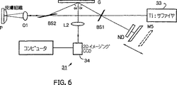
図6は、本発明によって構成され、試料の選択された光学的計測を行うための装置の他の実施例の概略的ブロック線図を示す。
図7は、図6の装置を使用して得られた2Dインターフェレンス・イメージである。
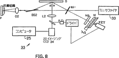
図8は、図6の装置の変更態様の概略的ブロック線図である。
図9は、図6の装置の変更態様の概略的ブロック線図である。
図10は、本発明の他の実施例を理解する上で有用な概略的線図である。
図11は、本発明によって構成され、試料の選択された光学的計測を行うための装置の更に他の実施例の概略的ブロック線図を示す。
図12は、オイル・ペインティングとその上のインシデント・パルス・インプリンティングとの断面構造図である。
図13は、図11の装置の一部を変更した概略的ブロック線図である。
図14は、図11の装置の他の変更例の概略的ブロック線図である。
図15は、図11の装置の他の変更例の概略的ブロック線図である。
図16は、図11の装置の他の変更例の概略的ブロック線図である。
図17は、図16の装置の他の変更例の概略的ブロック線図である。
図18は、図17の装置の他の変更例の概略的ブロック線図である。
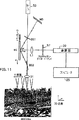
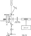
図19は、図11の装置の他の変更例の概略的ブロック線図である。
図20は、図11の装置の他の変更例の概略的ブロック線図である。
図21は、本発明によって構成され、試料の選択された光学的計測を行うための装置の更に他の実施例の概略的ブロック線図を示す。
図22は、図21の装置の他の変更例の概略的ブロック線図である。
図23は、図22の装置の他の変更例の概略的ブロック線図である。
図24は、図22の装置の他の変更例の概略的ブロック線図である。
図25は、図16の装置の他の変更例の概略的ブロック線図である。
図26は、図16の装置の他の変更例の概略的ブロック線図である。
図27は、図16の装置の他の変更例の概略的ブロック線図である。
図28は、図16の装置の他の変更例の概略的ブロック線図である。
図29は、本発明の装置の変更例の概略的ブロック線図である。
図30は、本発明の装置の変更例の概略的ブロック線図である。
好ましい実施例の詳細な説明
本発明は、生物医学的用途及び非医学的用途用の多機能高速相関−ドメイン干渉法及びシステムに関する。本発明は、顕微鏡的規模の物体を撮像するための単ショット超高速相関干渉(UCI)法を含む。本方法は、物体から反射したパターンの伝播時間を変換し、対応するコヒーレンス−ドメイン干渉パターンにする。このことによって、一実施例では、定置の回折格子及び直線状CCDアレイを使用することによって、他の実施例では、可動回折格子及び多チャンネルダイオードアレイ及びデモジュレータによって、反射を同時に整合させることができる。
次に添付図面を参照すると、第1図には、本発明に従って形成されたシステムの一実施例が示してあり、この実施例には、参照番号11が附してある。
システム11では、衝突−パルスモード−ロックトレーザー13を増幅器装置15で増幅し、第1ミラーMIで反射させ、第1ビームスプリッターBS1に当て、基準ビームとして役立つ透過部分及び信号ビームとして役立つ反射部分に分割する。増幅器装置は、一対の可動ミラーMM1及びMM2、及び一対の固定ミラーM3及びM4、及び増幅器システム21を含む。
基準ビームは、中密度フィルタNDを通過し、基準ミラーM5に当たる。基準ミラーM5からの光パルスは、中密度フィルタND及び第1ビームスプリッターBS1を通過して戻り、反射回折格子Gに入射する。格子Gは、垂直方向に配置された溝を持つように配向されている。
第1ビームスプリッターBS1を透過した信号ビームは、第2ビームスプリッターBS2を通過し、試料Sに設けられた球形レンズO1によって焦合される。試料Sから反射された光パルスは、第2ビームスプリッターBS2から反射され、格子Gに入射する。
試料S及びミラーM5からの反射は格子の法線に関して格子に入射し、そのため、正及び負の1次及び2次(又はこれよりも高次)の回折オーダー(各信号パルス及びその対応する基準パルスから)が法線に沿って伝播する(p sinα=λ、ここで、pは溝間の間隔であり、1/1200mmである)。レンズL1が回折光を集め、格子Gの共役画像平面に配置された直線状CCD検出器23に光を焦合する。CCDアレイ23は、単一の信号及び基準パルスから回折オーダーを通過させることができる入力シャッター(図示せず)を含む。深さ走査即ちZ軸方向走査と一致するCCD検出器23の出力をコンピューター25に供給し、ここでCCD23からの出力を処理する。
本発明による時間遅延格子発生式試料深さ走査(time delay grating−generated sample depth scan)の一例は、第2図を参照することによって更によく理解されるであろう。第2図でわかるように、回折格子は、基準パルスと試料によって格子分散方向(X軸方向)に反射されたパルスとの間に連続的な光学的遅延を導入する。この場合、試料の前面及び後面が反射したパルスは、回折格子によってX軸方向に分割され、その結果、深さ走査反射(depth scan reflection)を示す干渉最大値(interference maxima)もまたX軸方向に分割される。この行路差は、以下の式で表される。
Δ=cγ=2x sinα=2λx/p・・・(1)
ここで、λは波長であり、xは直線座標であり、γは基準パルスと信号パルスとの間の時間的遅延である。時間ディスプレーウィンドウ(time−display window)は、以下の式で表される。
γ=2λD/cp cosα・・・(2)
ここで、Dはビームの直径である。D=3mm、λ=620nm、p=1/1200mm、cosα=0.73の構成については、Td=20psの時間ディスプレーウィンドウが得られ、これは、一回の計測で最大3mmの試料深さに相当する。
CPMレーザーの代わりに、光源は、任意の広帯域光源であるのがよい。
本発明の相関アプローチを単モードファイバのクラッドの厚さの計測に関して第3図に概略に示すように試験した。ファイバに亘って計測した反射率分布(reflectance profile)を第4図に示す。コアの屈折率(nc=1.492)及びクラッドの屈折率(ncl=1.417)を使用し、コアとクラッドとの境界での反射能が−33dBであり、クラッドと空気との境界での反射能が−15dBであると決定する。クラッドの厚さdは19μm(d=Δ/2nclが試料内への距離であり、Δは工学的遅延である)であると決定された。
このシステムは、1996年10月15日付けの光学書簡集第21巻第20号の第1682頁乃至第1684頁のI.ゼイリコビッチ及び.R.Rアルファノの文献にも記載されている。同文献に触れたことにより、その文献に開示されている内容は本明細書中に組入れたものとする。
本発明の超高速法は、組織学的写真を撮影するため、反射能を持つ生物学的及び医学的構造の非接触診断にも利用できる。これは機械的不安定性に影響を及ぼさないためである。深さziのところにある反射能を持つ層の各々をその位置を示す信号として得る。
以下に示すように、本発明による干渉システムは、光記憶システム、例えば穴あけホログラフィー(hole−burning holography)から取り出されたパルスコード信号のレシーバーとして光通信にも使用できる。蓄積された光子エコー読み出し速度は、オクタエチルポリフィンでドーピングしたポリスチレン試料に分光穴あけによって記憶された10-15秒の4パルスパケットについて単ショット相関探知法を使用することによって、毎秒27テラビットであることが示された。
第4a図は、単ショットをベースとしたエコー4パルスパケットの相関探知を示す。単ショット干渉パターンのCCD画像(呼び出されたエコー4パルスパケットと相互参照パルスとの間)を第4図に示し、対応するデジタル化した相関探知トレースを第5図に示す。エコーパルスは、1.7psec.で分離した。干渉パルス及びエコー信号の相互探知は、初期パルスパケットの一時的分布の良好な単ショット再現を示し、150×10-15秒毎に4ビットの情報を提供する。これは、毎秒27テラビットの読み出し速度と一致する。
20ms程度の短い捕捉時間で生物学的組織の干渉二次元(深さ×横軸)画像をつくりだすのに使用できる。GIMと呼ばれるこの格子発生式干渉顕微鏡法は、皮膚組織の高解像度画像の発生に適用される。
二次元画像を得るため、本発明を例示するために使用された実験試料の概略図を第6図に示す。これには参照番号31が附してある。システム31は、増幅器装置15が省略されており、光源がCPMレーザーでなくTi:サファイヤレーザー33であり、L2が円筒形レンズであり、O2が円筒形レンズであり、CCD34が二次元画像アレイである点でシステム11と異なっている。鶏の皮膚組織試料(厚さが約3μm)をガラスプレート(P)の表面に取り付ける。レンズO(f=5cm)によって信号ビームをガラスプレートPの表面上に焦合する。その結果、鶏の皮膚上でのビームのスポットの大きさは約0.3mmであり、これが横方向座標画像を決定する。格子平面をレンズL2によって1024×1024ピクセルのCCDアレイと光学的に共役させ、二次元干渉画像を記録する。
回折格子は、格子分散方向(X軸方向)に連続的光学的遅延(生物学的深さ走査を行う)を導入する。上述の実験装置については、D=2.5mm、λ=800nm、p=1/1600mm、cosα=0.877であり、γd=13.5psの時間ディスプレーウィンドウが得られ、これは、最大2mmの試料深さ走査に相当する。
信号として定義された第1干渉パターンをCCDを整合した後、基準として定義された第2CCDの露呈を適用し、これについて基準と信号パターンとの間の干渉を破壊する。
GIMのダイナミックレンジ(DR)は、計測可能な最大CCD干渉信号のノイズに対する比によって定義され、
DR=10 log(SNR) (3)
である。
読み出しCCDシステムノイズ(暗中(in the dark))等の幾つかのノイズ源があり、ノイズの光学的計測値は、
SNR=W2 max/W2 max=(ρsj)2 max/(ρsj)2 max (4)
である。ここで、WはCCDカメラが検出した信号であり、この信号はCCDアレイに当たる光と比例する。GIMのダイナミックレンジは、CCDアレイのDRで決まる。CCDカメラのSNRは、比(Wmax/Wmax)と等しく、この場合、(DR)max=(DR)2 maxである。「DRが14ビット」のCCDカメラのDRは、約10 log(1.6×10⁴/1)であり、これにより、80dBの潜在的ダイナミックレンジ(DR)maxが得られる。
GIMの感度(S)は、以下の式によって定義される。
S=10 log〔(ρsj)2 min〕 (5)
等式3乃至5を使用することにより、GIMは、以下の式で表される。
S=10 log〔(ρsj)2 max〕−DR (6)
基準パルス及び信号パルスの振幅が等しい場合にCCD出力信号が最大になる。W2 maxを変化させることができるということを考えると、中密度フィルタを基準ビームに入れた場合、フィルタを2回通過する光学的密度(OD)refは、以下の等式の通りである。
(OD)ref=−log〔(ρsj)2 max〕 (7)
等式6乃至7を使用することにより、感度は、以下の式で表される。
S=−10(OD)ref−DR (8)
等式(8)は、GIMの重要な特徴を示す。SをGIMのDRとは別に増大できるのである。セットアップ時には、(ρsj)2 min=10-10であり、DR・70dBであり、等式(8)において(OD)refは3であると計算される。
鶏の皮膚組織の二次元干渉画像(信号及び基準画像を取り除いた後)を第7図に示す。
30mwの出力のレーザーについて二次元画像を捕捉するため、迅速な20msの捕捉時間を必要とする。この時間は、他の方法の10倍速い。皮膚、膜、及び筋肉の横方向高解像度(<1μm)構造を最大1.5mmの付加あに亘って視覚化できる。
システムの感度及び干渉システムのダイナミックレンジを高めるための別の方法を第8図のシステム33に示す。システム33では、基準ミラーM5をPZTトランスジューサ35によって二つの位置まで移動する。行路差はλ/2に等しい。ここで、λは、光源の中央波長である。基準ミラーM5の位置は、光検出器PZTフィードバックループ37によって二つの画像を獲得するように管理される。これらの画像のうちの一方はバックグラウンド+信号であり、他方の信号は、バックグラウンド−信号である。これらの信号は、PZTの二つの位置と対応する。フィードバックループ37は、駆動装置39及び光検出器41を含む。これらの二つの画像を差し引くことによって、感度が2倍の二次元(深さ−横方向座標)暗野干渉画像を発生する。このようにして、バックグラウンドを除去し、信号を2倍にする。(バックグラウンド+信号)−(バックグラウンド−信号)=二つの信号の2倍である。
データ獲得速度を増大させ、背景のノイズを取り除くために、干渉計システムは図9に示すように構成することができる。参照番号43により同定される図9のシステムでは、焦点合わせ用レンズL3、音響光学的モデュレータ(AOM)、90度反射プリズム45、2つの中性濃度フィルターND及び2つの反射ミラーM5が存在する。ミラーM5は、ビームがモデュレータAOMにより偏向させられ、そしてプリズム45の側面により反射されるように配置され、ミラーM5の一方が、回折角度−αで回折格子Gに戻るように向けられている。モデュレータAOMにより偏向させられたビームの周波数は、干渉が壊されるように変えられる。干渉を持つCCDフレーム及び干渉を持たないCCDフレームは、一方が他方から連続的に減じられ、一連の2D(深さ−横方向の座標)暗部領域の干渉画像を生成する。システム43の残りの構成要素は、図6のシステム31と実質的に同一である。
シングルスポットのパルスで格子状に生成されるコヒーレントな走査に対して、CCD直線状アレイとコンピュータメモリとの時間応答は1msである。反復率は、103 l.p./sより良好にすることができない。理解することができるように、基準パターンが背景ノイズを減じるために各々の軸方向走査に対して必要とされる。全軸方向走査は、反復率500 l.p/sで少なくとも2msを必要とする。反復率500 l.p/s及び動脈走査時間20msを使用した場合、横方向のほんの10ピクセルだけが生成される。このシステムは、非常に速い軸方向の偏向で物体をイメージングするためには有用であり得るが、横方向には小さいサイズのサンプルしかイメージングできない。従って、データ獲得速度、サンプル走査サイズ、光学相関領域のイメージングの信号対ノイズ比率を増大させるために追加の方法が必要とされる。
本発明の他のバージョンは、光ビームが、移動する回折格子(DG)によって回折されるとき、回折された光の周波数がドップラーシフトを有するという原理を用いている。一定速度vで格子分散方向(x軸)に動く回折格子DGを考えてみよう。図10に示される通り、基準(信号)ビーム方向上への速度ベクトルVの射影成分は、Vr, s=±sinαである。ここで、±αは基準(信号)ビームと格子DGに垂直な方向との間の角度である。回折された基準ビームと信号ビームとの間のドップラー周波数シフト量(DFS)は、次式のようになる。
△fD=2vf0sinα/c=2v sinα/λ0=2v/p (9)
ここで、pはDGの溝の間の空間間隔であり、f0及びλ0は、各々、光の周波数及び波長である。
例えば、v=30mm/s、p=0.001mmの場合、△fD=230/0.001=60kHzである。出力干渉信号は、△fDに等しい周波数で一時的に変調される。
移動格子配列を示し参照数字51により識別されるシステムが図11に示される。システム51は、レーザー光源53、第1ビームスプリッタBS1、第1ビームスプリッタBS2、格子DG、基準ミラーM5、格子DGを移動させる並進器55、焦点レンズ01、集光レンズL1、マルチチャンネルダイオード列57、デモジュレーター59、及びコンピュータ61を含む。システム51は、システム31とは、主に、格子が可動であること、検出器がマルチチャンネルダイオード列及びデモジュレーターである点において異なる。図示のように、格子DGからの光学信号(即ち、分散光)は、マルチチャンネル線形列(L.A)検出器57へ向けられる。光学信号は、マルチチャンネルダイオード列57の出力を、ドップラー転換周波数(DSF)で復調することにより検出される。出力信号 Wf(T)は、次式で与えられる。
Wf(T)〜Rouρsj|Y(T−Tj)| (10)
ここで、ρsjは、サンプルの内側のj−th境界の反射量(反射強度の平方根)、|Y(T−Tj)|は、コヒーレンスの程度である。式4の和は、各反射信号が、反射力ρsjに比例する干渉パターンへの寄与を生じる。異なる時間遅れで対象物の内側に広がる反射層から来る信号が、反射力ρsjに比例する干渉パターンへの寄与を生じる。各反射ピークの半極大における全幅(FWHM)が、増大相関時間、この方法の解を決定するコヒーレンスの程度|Y(T−Tj)|のFWHMに等しい。反射側の位置を決定できる精度は、ダイオード列の分解能にのみ依存する。もし各ダイオード列ピッチの処理時間である△fD=60Khzならば、AC信号は、概略、10/60×103≒0.1ミリ秒である。AC信号の処理は、全てのピッチで平行に行われる。各軸方向走査に対する0.1ミリ秒の応答時間と104 l.p./sの走査反復速度が、達成可能である。周波数変調干渉計について、100dBの信号ノイズ比(SNR)が達成可能である。この方法は、低いコヒーレントな光で組織を表示することによる高解像度横断画像、及び格子発生時間遅れの関数としての後部散乱光又は異なる横断位置の範囲の測定を遂行する。
図11のシステムにおいて、サンプルSは、立体像を提供するように、図示しないステージ上に「X」方向において図示しない手段により可動に装着される。もしサンプルがX方向において可動でないならば、(サンプルに対して)単に2次元の像が得られる。
図11のシステムは、光学的像の非接触、高感度、高解像度の技術を提供する。高速走査速度は、特に医療及び生物学的診断の用途に適当である。眼及び組織の組織学的構造が特に関連するのは、頭部に近い眼の特質及び組織の診断の非侵襲性の測定である。生物学的システムにおける診断に加えて、高速度格子発生深度走査は、精密機械的及び光学的装置の非接触診断への多数の用途、並びにプロセス制御及び製造の監視への用途を有する。
組織の見本を採取する必要なく、血管の内部構造又は粘膜の内部構造のような、組織の構造形態の光学的組織学的マップ(高解像度微小寸法横断面光学像)を達成するこの技術は、診断、及び組織変化の医療処置に対し力強い影響を有するであろう。
血管内の超音波は、人間の血管の横断像を得る現存するカテーテルに基づく技術である。しかしながら、本発明の技術は、血管障害をより高い解像度で描く能力を有し、動脈、皮膚、又はGYN、GI系又は嚢のようなその他の器官の高解像度の像を得るために臨床的に有用である得る。
既存の又は共焦入射光の顕微鏡による着色サンプルの断面分析は、絵画を保存するための最初の試験の間に、材料の構造を研究しそれらの成分を同定するため日常的に行われる。本発明の技術は、得られる解像度の増加だけでなく、通常の顕微鏡検査に多数の重要な利得を有し、立体像にされる100dBの高い信号ノイズ比を有する小さいZ方向深さの高速度連続光学断面を作る能力を有する。本発明の主要な利点は、本発明が、絵画の層の境界及びそれらの厚さを正確に決定する高速の比較的安価な方法を提供することである。この技術は、重ねた着色が、前の保存のため、なされたかどうかを決定するため使用可能であり、高い倍率及び感度で、色素粒子の識別のため使用され得る。油絵の典型的な断面構造を描く線図を図12に示す。図12において、(A)は、ごみ沈積粒子であり、(B)は、ワニス層であり、(C)は、ペイント層(乾燥油媒体中の色素粒子)であり、(D)は、背景層(乾燥油媒体中の鉛白)、にじみ止め(通常は、動物性ののり)が浸漬されたキャンバス支持体(通常は、リネン)である。入射パルスは、これらの層で反射される。反射パルスとパルス強度との間の時間遅れは、層の深さと反射性についての情報と一致する。この情報は、本発明の干渉システムを使用して抽出され得る。
格子状に生成されたコヒーレントな深さの走査、ドップラー周波数に変調された干渉及び多重チャンネルの検出器の同時登録の特性を結合させることによって、データ獲得速度及び空間分解能の増大が達成される。
回折された基準ビームと信号ビームとの間のDFSは、矢印Bにより示されたように、DGがその平面に沿って圧電トランスデューサ(PZT)により振動させられ、これにより格子変位が格子溝空間より大きくなる場合にも得ることができる。この技術は干渉計の機構部分を簡単にすることができる。
本発明の他の態様によれば、データ獲得速度は、一定の角速度ωで回転される回折格子を用いることによって増大される。格子接線方向速度vtの増加が図14に示されたシステム71で達成される。システム71では、格子DGがモータ(図示せず)のドライブシャフト75にアーム73(図示せず)により取り付けられる。免速度ω=8×10³で円半径が5cmの場合、vt=ωr=8×103×50/60=6×103mm/s及びDFS△fD=2ωr/p=2×6×103/10-3=12MHzとなる。各々のダイオード列ピッチのAC信号処理時間は、約10/12×106≒1μsである。各々の軸走査に対する1μsの反応時間及び100 l.p.sの走査反復率(SRR)を得ることができる。
データ獲得速度を増大させるいくつかの方法がある。
データ獲得速度を増大させる1つの方法は、多角形筒装置の各辺に配置されたいくつかの回折格子を使用してSRRを増加させることである。これらの格子は、装置の長さ方向軸の回りに回転され、信号ビームはx(又はy)方向に離散的に走査しており、これによって各々の回折格子の位置は、走査システムにおけるある一定のx(又はy)位置に同期的に反復される。長さ1cm当たり約30個の格子を、円半径5cmに対して使用することができる。SRRは3×10³ l.p./s.2である。回折格子が一定の角速度で回転する円筒表面CS上に載せられている場合、SRR及び横分解能の最大値を得ることができる(図16を見よ)。SRRは、1μsの軸方向走査時間反応に対して1MHzである。軸方向走査分解能を増加させるため、干渉画像出力は、ファイバー直線状アレイFLA(図17を見よ)により集められる。各々のファイバー出力は、ある一定のダイオードアレイのピッチで接続される。各々のL.A.ダイオードピッチのサイズは、1mmである。シングルモードのファイバーの直径は約100μmであり、このとき軸方向分解能の10倍の増加を達成することができる。
多重チャンネルの光検出器LA及び電子検出システムを簡単化するため、回折格子及び多重チャンネル光検出器で接続されたファイバー直線状アレイが、速く動くトランスレータ上に取り付けられている(図18を見よ)。
レーザ源の中心波長(λ)が離散的に調整されるとき、溝空間pが関係p=λ/sinαを満足しなければならない。ここで、±αは基準(又は信号の)ビームと回折格子に直角方向との間のなす角度である。いくつかの同一平面内の回折格子の構成を使用して様々に異なる溝間隔を実行することができる(図12を見よ)。構成格子の垂直位置が、関係式(3)を満足させるようにYトランスレータにより離散的に変えられる。
本発明の他の実施例(図20のシステム71を見よ)では、光源はダイオードレーザLAのアレイであり、その各々は関係式(2)に従って様々に異なる波長λで光を照射する。LAレーザ源は、ホルダーの上、y(又はx)移動ステージの真ん中当たりに取り付けられる。一つのレーザダイオードの位置は、1つの回折格子の位置と同期されている。その波長は、最大深さの照射に対して、典型的には600nm乃至1600nmまでの範囲で選択される。
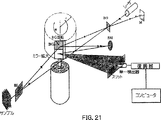
電子検出システムを簡単化し、ダイオードLAの代わりに一つの検出器を使用するため、図21のシステム73に示されるように、反射ミラーMEの形態で垂直方向伸長機能を備えた回転する回折格子DGが用いられる。回折されたビームは、静止した球形ミラーSMから反射される。このミラーSMはこれらのビームを垂直方向に変位させ、それらを回転する反射ミラーMEに戻すように反射させる。回転するミラーMEから反射されたビームは、垂直スリットVSの中に向けられる。このスリット平面は、反射球形ミラーSMにより格子平面と光学的に共役である。このスリットを通過する光学信号は、信号ビームと回転する格子RGにより生成された基準ビームとの間のドップラーシフト周波数で単一の検出器出力を復調することによって検出される。
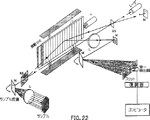
格子DGを振動させるPZTを用いる機械システムを簡単にするため、回折信号と基準ビームとは図22のシステム75に示されるように小さい角度で振動する反射ミラーSRMから反射される。
回折格子を追加することなくSRRを増加させるため、反射するミラーにより垂直方向の伸長機能を備えた球形(或いは円筒形)反射表面上に載せられた回折格子を振動させる小角度振動機構SASMを使用することができる。この小角度の振動軸は、格子球形(或いは円筒形)反射表面(図23を見よ)の中心を通過する。
データ獲得速度を増加させるため、干渉計システムが実行され、これによって振動する(又は回転する)格子から反射されたビームが、格子の振動(又は回転)軸上に配置された振動する(又は回転する)反射ミラーSRMに向けられ、このミラー反射の後に、多重チャンネルの光検出器に連結された静止したファイバーアレイに向けられる。(図24のシステム77を見よ)
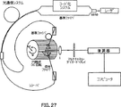
例えば動脈断面、組織断面又は粘液などの人体内部組織の表面構造の画像を得るため、信号及び基準の干渉計アームが、図25のシステム79に示すように、ファイバー連結される。格子状に生成された深さの走査及び復調された干渉エンベロープの大きさをディジタル表示することにより組織反射率が軸方向に得られる。信号ビームのファイバー入力はカテーテルに接続され、ファイバー出力は、回折角度αで信号ビームを格子に向けるレンズLE1に接続される。基準ビームのファイバー出力は、回折角度−αで基準ビームを格子に向けるレンズLE2に接続される。ファイバーの光学的諸特性は、干渉計設定のフレキシビリティを改善することを可能にする。カテーテルは、その中に該カテーテルが挿入されるところの脈管(或いは他の生物学的構造)を通って断面状に画像を得るため、円周パターンでビームを走査するように設計される。画像獲得の間、カテーテルは、その画像が得られる組織構造(動脈又は他の内部組織チャンネル)の中に挿入され、駆動モータ(図示せず)がオンになったとき、カテーテルのシャフト及び末端の光学構成部分がカテーテルの軸に垂直にフォーカスされたビームを円周状に走査する。ビーム回転角度がある範囲(通常、360度)に亘って変化するとき、画像が得られる。画像獲得速度は、回転速度及び提案された干渉計のデータ獲得速度に依存する。
この干渉計システムは、例えばホールバーニングホログラフィ(hole-burning holography;図26のシステム81を見よ)などの光学的記憶システムから引き出されるパルスコード信号のレシーバとしての光学的相互伝達手段のために使用することができる。時間領域の光学データの格納の場合には、比較的強い読み出しビームの存在にも係わらず、時間的及び空間的にきわめて接近した状態で信号ビームを検出しなければならない。強い読み出しビームの存在は、提案された技術を使用することによって、有利な点に転換することができる。我々のアプローチは、きっちりとフォーカスされたビームと角度をなして励起されたビームとの間のオーバーラップの必要性、及び、強い励起ビームによる検出器の飽和を防止するための光学シャッターの必要性を無くしてしまう。他の有利な点は、隣接する空間格納セルの間のクロストークを最小化する能力、及び、フォトダイオードをベースとした検出システムのノイズレベルを克服するため十分に信号を増幅させる能力を備えることである。パルスコード信号は回折角度αで格子上に向けられ、コヒーレントな基準パルスは回折角度−αで格子上に向けられる。20psの時間遅延窓及び100fsのパルス振幅相関時間に対して、パルスコードは約2×103ビットを持つ。情報読み取り速度は、軸走査時間反応1μsに対する1MHzの反復率で、2×109ビット/秒である。SNRは約100dBである。
経済的な効果、成熟する技術及び高い情報能力の故に、シングルモードの光ファイバー相互伝達メディアが将来の遠距離通信ネットワークに埋め込まれるであろう。これら将来の光学ネットワークの望ましい特徴は、多重送信、フィルター処理、増幅、及び相互関係という目的のため、光学領域において、直接、情報を処理する能力となるであろう。光学信号処理は、電気信号処理より遙かに速くすることができ、また、光子−電子−光子間の転換の必要性を無くすことができるので、大きな効果を奏することになる。
弱く非常に短い強度という特徴は、時間領域のコミュニケーションのための単一事象の検出にとって本質的に重要である。非常に速い時間領域のデータパケットは、モード固定されたレーザパルスのフィルター処理により生成することができる。非常に短い時間領域信号の効率的な検出は、新しい受信システムを必要とする。提案された干渉計は、光学的相互伝達システム(OCS)(図27のシステム83を見よ)から受信された、パルスコード信号のレシーバーとして実行することができる。このパルスコード信号は、回折角度αで格子上に向けられ、OCSから引き出されたコヒーレントな基準パルスは回折角度−αで格子上に向けられる。
サブピコ秒レーザー源の開発は、かようなレーザーからのパルスの正確で完全な特性用の多くの予防技術を有する。今日、最も一般的に用いられる測定は、非線形自己相関法である。この技術は、一般に高強度パルスを必要とする。フェムト秒パルスのスペクトルフェーズ(位相)は、周波数ドメイン相関計を用いて測定することができる。この技術は、オリジナルパルスの相互相関する異なるスペクトルスライスを含む。相互のスペクトル要素の相対的な遅れは、存在するかもしれないチャープについての情報を提供する。干渉計は、信号ビームがゼロ分散ストレッチャーを含み、スペクトルストレッチャー面に置かれたスリットを移動させることで、スリット位置における出力信号位置の依存関係を測定するように
機能し得る(図28のシステム85を参照せよ)。これらの測定により、測定感度及び取得速度を増加する入力パルスのスペクトルフェーズを得ることが可能となる。
図29におけるシステム91において、信号ビーム及び対照ビームは、円柱レンズの組み合わせにより、格子表面及び2D−CCDアレイ上の狭い線上に収束する。この狭い線の位置は、たとえば、信号ビームの側面位置がCCDアレイ上の垂直にシフトした狭い線を生じるように、回転する鏡により垂直方向において、CCDアレイ上で変化する。いくつかの深度−側面ディジタルイメージは、異なるフェーズシフトと共に記録される。これらのイメージは、ディジタル処理されて、3Dイメージを作り出す。
図30に示すシステム99において、信号:ノイズ比の増加は、信号ビーム及び対照ビームが回折格子に収束する干渉計システムを用いることで増加する。光学出力信号は、ドップラーシフト周波数における信号検出器出力を復調することにより検出される。
本発明の別の実施形態(図示せず)において、干渉計システムは、サンプルの表面上のソースの線形イメージがたとえば90度回転できるように構築される。PZT延伸ファイバーが挿入されて、フェーズ変調をなす。いくつかの深度−側面イメージは、異なるフェーズシフトで2DイメージングCCDアレイによって記録される。これらのイメージは、ディジタル処理されて、サンプルの内部構造の3Dイメージを作り出す。
本発明の別の実施形態(図示せず)において、2個の垂直線形ソースは、サンプルを同時に照射する。溝の垂直方向を有する2本の回折格子は、2本のCCDアレイ上に2個のイメージを同時に作り出すために用いられて、サンプルの内部構造の3Dイメージ処理用の信号を作り出す。
本発明の別の実施形態(図示せず)において、同じ位置又は異なる位置に置かれた2本の直交格子、1本又は2本のCCDアレイは、格子分散に沿ってサンプルの深度のZ軸走査と組み合わせたX方向又はY方向におけるイメージを作り出すために用いられる。CCDアレイによって作り出されたイメージは、サンプルの3Dイメージを作り出すために用いられる。
本発明の重要な特徴は以下の通りである。
1.±一次(又はより高次の)回折次数における対照パルスの干渉により、材料から反射した信号を時間分析するために回折格子を用いること。
2.層からの反射した信号及び散乱媒体における欠陥に対する深度マップ情報を得るために時間分析干渉方法を用いること。
3.領域内での反射から3mmまでの表面下の散乱媒体の深度マップを得るために時間分析干渉方法を用いること。
4.数mm深度以内の組織、半導体構造物、生物学的対象上のアートワークの深度分析用に時間分析干渉方法を用いること。組織分析としては、組織における組織学的変化及びプラーク、脂肪、脂質沈着物(アテローム性物質)などの動脈壁における組織学的変化を検出するために用いることもできる。
5.格子発生コヒーレント深度走査干渉計及び広帯域レーザー源を用いるシングルショット相関ドメイン干渉計システム。正及び負の一次回折信号ビーム及び対象ビームは、格子に対する垂線に沿って伝搬する。回折格子は、対象パルスと格子散乱方向(X軸)においてサンプルによって反射されたパルスとの間に連続的な光学的遅れを導入する。この場合に、サンプルの内側に配置された表面によって反射されたパルスは、X方向の回折格子によって分割され、深度走査反射を示す干渉の最大値はさらにX方向に分割されて、CCDアレイを用いる反射の同時記録を可能とする。深度Ziにおける各反射層は、その位置を位置づける信号として得られるであろう。
6.解像度の高く、ダイナミックレンジの広い2D(深さ−横軸)干渉像を得るために、干渉システムの基準干渉アームは反射鏡を備える。反射鏡は、二つの異なる位置へ移動可能で、その通路差は格子時間−表示窓(Td≦20ps)及び可変ニュートラル−密度フィルターより大きい。PZTストレッチ型ファイバーを挿入すれば遅れ時間をTdより長くすることができる。信号アームは、円筒形(球形)の凸レンズ又はそのコンビネーションを備え、例えば、サンプルの表面および整合システムにリニアーソース像を画成する。これにより二つの像が得られる。2D像CCD列は、基準鏡の二つの異なる位置に対応した干渉付き(信号)及び干渉無し(基準)の二つの像を連続的に得る。信号像と基準像はコンピュータで減算され、2D暗視野干渉像が画成される。
7.システムの感度を高め且つ干渉システムのダイナミックレンジを広げるために、基準鏡を備える。基準鏡はPZTトランスデューサによって二つの位置に移動可能である。その通路差はλ/2に等しい。λは中央波長源である。基準鏡の位置は光センサー−PZTフィードバックループによって管理され、二つの像を得る。その一つはバックグランド+信号で、他の像はバックグランド−信号で、PZTの二つの位置に対応する。これら二つの像が減算されると、二重感度の2D(深さ−横軸)暗視野干渉像が画成される。而してバックグランドは除去され、信号は二倍、即ち二つの信号、(バックグランド+信号)および(バックグランド−信号)が得られる。
8.データの取得得度を速めると共にバックグランドを取り除くために、干渉システムは基準アームを使用する。基準アームは、集束レンズと、音響光学変調器(AOM)と、90度反射プリズムと、二枚の反射鏡とを備える。二枚の反射鏡はプリズムの反射面に対向して設けられ、AOMによって偏向され且つプリズム面の一つ及び反射鏡の一つから反射したビームはαの回折角度でもって回析格子に戻される。干渉付き及び干渉無しのCCDフレームは連続的に減算され、一連の2D(深さ−横軸)暗視野干渉像が画成される。
9.光学的断層撮影及び組織学的であるカテーテル−内視鏡による断層撮影を実施するために、一発式干渉システムが使用される。このシステムでは、信号ビームが例えば回転鏡によって走査され、サンプルを異なる横位置から照光する。これらの信号は、各横位置において、狭いZ−深さの光学セクションを形成する。一連の光学セクションは次いで3D像として表すことができる。
10.データ取得速度、空間的解像度及びSN比を高めるために、干渉システムは回析格子を備える。回析格子はその面に沿って一定の速度で移動し、信号ビームと基準ビームとの間のドプラー偏移周波数を発生する。光学信号はドプラー偏移周波数で多重チャンネルリニアー列(LA)センサーの出力を復調することによって検出される。回析格子の別実施例においてはその面に沿って例えば圧電変換器(PZT)を使用して、格子の変位を格子の溝空間より大きくする。
11.接線方向の速度、DFS及び取得速度(acquisition speed)を増加するように一定の角速度で回折格子を回転すること。別の態様では、幾つかの回折格子が多数の側部を有する円筒形ユニットの側部に配置されている。これらの格子は中央部を貫通する軸線の周りに回転され、そして、各々の回転する格子の位置が操作装置の一定のX(又はY)方向の位置に同期されるように信号ビームがX(又はY)方向に別々に走査する。
12.一定の角速度で回転する円筒形の表面に担持された回折格子を使用して、X(又はY)方向走査装置の取得速度及び横方向解像度を増加する。
13.干渉計の軸線方向解像度を増加するため、干渉イメージ出力がファイバーの線形配列で収集される。各ファイバーからの出力は一定のダイオードアレイピッチに接続される。
14.多チャンネル光検出器LA及び電子検出装置を簡単化するため、多チャンネル光検出器に連結された回折格子とファイバー線形配列とが高速トランスレータに相互に配置されている。
15.回折格子は複数の溝の間に異なった間隔で設けられた幾つかの共通平面にある回折格子の組成体を備えている。レーザー源の中央部の波長(λ)が組成体の位置で別個に整調されるとき、格子が別個に変化して、溝間隔Pが次の方程式P=λ/sinα(1)を満足する。ここで、±αは基準(若しくは信号)ビームの間の角度であり回折格子に垂直である。
また、レーザー源は別の波長λ(400ないし600nm)のレーザー源の線形配列である。レーザー源配列はホールダに装着されていて、適応するX(又はY)方向の中継ステージがレーザー源の適当な波長を選択することを可能にする。
16.最大組織吸収波長における短波長放射を使用して組織画像の感度を増大するため、干渉計装置は第2高調波で放射するようにされたレーザー源を使用している。
17.請求項7ないし11の干渉計装置において、回折格子の垂直方向伸長部が反射鏡を有している。回折されたビームは静止した球形鏡で反射される。この球形鏡はこれらのビームを垂直方向に向け、かつそれらビームを回転する反射鏡へ戻す方向に配向する。回転する反射鏡から反射されたビームは垂直方向のスリットに向けられる。スリットの面は球形の反射鏡により格子面で光学的に結合される。スリットを通る光信号は回転格子により生成された信号と基準ビームの間のドップラー遷移周波数での単一の検出器出力を復調することにより検出される。この技術は単一の検出装置を使用することを可能にする。
18.データ習得速度を増加させるために、干渉システム、シェイキング(即ち回転)回折格子から反射されたビームが、回折格子のシェイキング軸(回転軸)に配置されたシェイキング(回転)ミラーに向けられ、ミラーで反射した後、マルチチャンネルフォトディテクタに接続された固定ファイバアレイに向けられる。
19.電子検出を容易にするために、PZTシェイキングDG信号での干渉システムと参照ビームが、小角度シェイキング反射ミラーから反射される。シェイキングミラーで反射されたビームは垂直スリットに向けられる。スリットを通過した光学信号は、ドップラーシフト周波数でシングルディテクタ出力を下方変調することにより検出される。
20.追加の面折格子なしにSRRを増加するために、回折格子が球形(円筒形)反射面に形成され、小角度で振られる垂直伸長反射ミラーを備える。小角度シェイキングの軸線は回折球形(円筒形)反射面の中心を通る。
21.人の内部器官、粘液または組織、例えば動脈のサブ構造の像を得るために、信号参照干渉アームをファイバ結合する。信号ビームファイバの入力は例えばカテーテルに接続され、ファイバの出力はレンズに接続され、該レンズは回折角度αで信号ビームを回折格子に向ける。参照ビームのファイバ出力はレンズに接続し、該レンズは参照ビームを回折角度−αで回折格子に向ける。
22.光学記憶システム、例えばホールバーニングホログラフィから検索されたパルスコード信号のレシーバとして干渉システムを使用する。パルスコード信号を回折角度αで回折格子に向け、コヒーレントな参照パルスを回折角度−αで回折格子に向ける。
23.光学伝達システム(OCS)から受けたパルスコード信号のレシーバとして干渉システムを使用する。パルスコード信号を回折角度αで回折格子に向け、OCSから抽出されたコヒーレントな参照パルスを回折角度−αで回折格子に向ける。
24.干渉システムがゼロ分散ストレッチャを有する信号ビームを有し、ストレッチャスペクトル面内に配置されたスリットを移動して、スリット位置での出力信号位置の依存を測定する。これらの測定により、入力パルスのスペクトル位相を得ることができる。Cross-reference with related applications
This application claims the benefit of US Provisional Patent Application No. 60/033220, filed December 4, 1996, and US Provisional Patent Application No. 60/042489, filed April 2, 1997. The patent application is incorporated herein by reference.
Background of the Invention
The present invention relates generally to methods and systems for performing optical measurements, and more particularly to methods and systems for performing optical measurements using optical coherence domain reflection techniques.
Optical coherence domain reflection (OCDR) is a well-known technique, based on the detection of interfering signals, with a precision of 10 um resolution and precision providing a dynamic region of more than 100 dB up to several millimeters for a depth scan. It is an attractive way to make measurements. When a high-speed linear conversion stage is used, OCDR measurement can be performed at a moderately high speed. This method can be used to determine an internal depth image below the surface. OCDR has been developed for anterior and retina imaging, optical tomography and histology in highly diffusive media, and catheter-endoscopy of internal organs. The mirror speed is usually in the range of 30 mm / min corresponding to a Doppler frequency of 50 kHz. In order to achieve very high image acquisition speeds, another technique of mirror conversion scanning must be developed.
US Patent No. 4,457,570 issued October 17, 1995 to AE Swanson et al. Provides a method and apparatus for performing various optical measurements using optical coherence domain reflection (OCDR). Yes. The short coherence optical radiation source optically emits the sample as well as the optical reflector through a similar optical path. The optical reflector moves according to a predetermined velocity profile, allowing interferometric scanning of the sample, and the resulting output has Doppler transform frequency modulation. This output can be demodulated and detected to obtain the desired measurement and other information. Additional information can be obtained by radiating the sample and reflector from two or more light sources with different wavelengths and demodulating the resulting output separately before processing. The birefringence information can be obtained by polarizing the optical radiation used by appropriately modifying the polarization in the sample and standard optical paths and dividing the output into orthogonally polarized outputs that are demodulated separately before processing. .
Another related reference technique is A. Knuttel, US Pat. No. 5,491,552, issued February 13, 1996.
It is an object of the present invention to provide a new and improved method and system for optically performing high resolution measurements.
Another object of the present invention is to provide a new and improved method and system for optically performing high resolution measurements using diffraction gratings.
Another object of the present invention is to provide a method and system for obtaining a 2D image of a sample without lateral scanning of the sample.
It is a further object of the present invention to provide a method and system for obtaining a 3D image of a sample.
Summary of the Invention
A system for selective optical measurement of a sample constructed in accordance with the teachings of the present invention includes a broadband light source that generates a broadband beam of light, means for splitting the light beam into a signal beam and a standard beam, and receiving the standard beam A standard mirror arranged to focus, means for focusing the signal beam on the sample, and a diffraction grating for receiving reflected light from the sample and reflected light from the standard mirror, Reflected light from the mirror and sample is incident at a right angle to the diffraction grating such that positive and negative first and second order diffraction from the reflected light propagates at right angles to the diffraction grating. And means for focusing the diffraction of the diffraction order from the diffraction grating and focusing the diffraction order on the detector, the positive and negative received by the detector. The first of And generating an output of the diffraction of the second rank in beauty, and a means for processing the output from the detector.
The method for performing selective optical measurement of a sample according to the present invention includes generating a light beam, dividing the light beam into a signal beam and a standard beam, and arranging a standard mirror along the optical path of the standard beam. And focusing the signal beam on the sample, and arranging a diffraction grating to receive light from the sample and light from the standard mirror, and reflection from the mirror and the sample. A pulse is incident on the grating at right angles so that positive and negative first and second order diffraction from the reflected light propagates at right angles to the grating, and a detector is placed Focusing the diffraction orders of diffraction from the diffraction grating, focusing the diffraction orders on the detector, and receiving the received positive and negative first and second order diffraction outputs. From the detector And it, and a processing the output from the detector.
In some embodiments, the diffraction grating is fixed and the detector is a one-dimensional linear CCD array. In contrast, in other embodiments, the diffraction grating is movable and the detector is a multichannel diode array whose output is fed to the demodulator.
Various features and advantages will be apparent from the description below. In the following description, reference is made to the accompanying drawings that form a part hereof, and in which is shown by way of illustration specific embodiments for carrying out the invention. These embodiments have been described in detail to enable those skilled in the art to practice the invention, other embodiments can be utilized, and structural transformations can be made without departing from the scope of the invention. Is understood to be able to. The following detailed description is, therefore, not to be taken in a limiting sense, and the scope of the present invention is best defined by the appended claims.
[Brief description of the drawings]
In the drawings, like reference numerals represent like parts.
FIG. 1 shows a schematic block diagram of one embodiment of an apparatus constructed according to the present invention for performing selected optical measurements of a sample.
FIG. 2 is a diagram showing a case where a time delay type lattice generation type sample depth scan is performed on the embodiment of the present invention shown in FIG.
FIG. 3 is a cross-sectional view of a sample tested using the apparatus of FIG.
4 is a graph of the reflectance profile across the sample of FIG. 3 measured using the apparatus of FIG.
FIG. 4A is a CCD image of a single shot interference pattern.
FIG. 5 is a digitized cross-correlation trace obtained using the apparatus of FIG.
FIG. 6 shows a schematic block diagram of another embodiment of an apparatus constructed according to the present invention for performing selected optical measurements of a sample.
FIG. 7 is a 2D interference image obtained using the apparatus of FIG.
FIG. 8 is a schematic block diagram of a variation of the apparatus of FIG.
FIG. 9 is a schematic block diagram of a variation of the apparatus of FIG.
FIG. 10 is a schematic diagram useful in understanding other embodiments of the present invention.
FIG. 11 shows a schematic block diagram of yet another embodiment of an apparatus constructed according to the present invention for performing selected optical measurements of a sample.
FIG. 12 is a cross-sectional structure diagram of oil painting and incident pulse imprinting thereon.
FIG. 13 is a schematic block diagram in which a part of the apparatus of FIG. 11 is modified.
FIG. 14 is a schematic block diagram of another modification of the apparatus of FIG.
FIG. 15 is a schematic block diagram of another modification of the apparatus of FIG.
FIG. 16 is a schematic block diagram of another modification of the apparatus of FIG.
FIG. 17 is a schematic block diagram of another modification of the apparatus of FIG.
FIG. 18 is a schematic block diagram of another modification of the apparatus of FIG.
FIG. 19 is a schematic block diagram of another modification of the apparatus of FIG.
FIG. 20 is a schematic block diagram of another modification of the apparatus of FIG.
FIG. 21 shows a schematic block diagram of yet another embodiment of an apparatus constructed according to the present invention for performing selected optical measurements of a sample.
FIG. 22 is a schematic block diagram of another modification of the apparatus of FIG.
FIG. 23 is a schematic block diagram of another modification of the apparatus of FIG.
FIG. 24 is a schematic block diagram of another modification of the apparatus of FIG.
FIG. 25 is a schematic block diagram of another modification of the apparatus of FIG.
FIG. 26 is a schematic block diagram of another modification of the apparatus of FIG.
FIG. 27 is a schematic block diagram of another modification of the apparatus of FIG.
FIG. 28 is a schematic block diagram of another modification of the apparatus of FIG.
FIG. 29 is a schematic block diagram of a modification of the apparatus of the present invention.
FIG. 30 is a schematic block diagram of a modification of the apparatus of the present invention.
Detailed Description of the Preferred Embodiment
The present invention relates to multifunctional fast correlation-domain interferometry and systems for biomedical and non-medical applications. The present invention includes a single shot ultrafast correlation interference (UCI) method for imaging microscopic scale objects. The method converts the propagation time of the pattern reflected from the object into a corresponding coherence-domain interference pattern. This allows one embodiment to use a stationary diffraction grating and a linear CCD array, while in another embodiment, the movable diffraction grating and multi-channel diode array and demodulator can simultaneously match reflections. it can.
Referring now to the accompanying drawings, FIG. 1 shows one embodiment of a system formed in accordance with the present invention, which is designated by the
In the
The reference beam passes through the medium density filter ND and strikes the reference mirror M5. The light pulse from the reference mirror M5 returns through the medium density filter ND and the first beam splitter BS1, and enters the reflection diffraction grating G. The grating G is oriented so as to have grooves arranged in the vertical direction.
The signal beam transmitted through the first beam splitter BS1 passes through the second beam splitter BS2 and is focused by the spherical lens O1 provided on the sample S. The light pulse reflected from the sample S is reflected from the second beam splitter BS2 and enters the grating G.
Reflection from the sample S and mirror M5 is incident on the grating with respect to the grating normal, so that positive and negative first and second order (or higher order) diffraction orders (each signal pulse and its corresponding reference). (From the pulse) propagates along the normal (p sin α = λ, where p is the spacing between the grooves and is 1/1200 mm). The lens L1 collects the diffracted light and focuses the light on the
An example of a time delay grating-generated sample depth scan according to the present invention will be better understood by referring to FIG. As can be seen in FIG. 2, the diffraction grating introduces a continuous optical delay between the reference pulse and the pulse reflected by the sample in the grating dispersion direction (X-axis direction). In this case, the pulse reflected from the front and rear surfaces of the sample is divided in the X-axis direction by the diffraction grating, and as a result, the interference maximum value indicating the depth scan reflection is also in the X-axis direction. It is divided into. This path difference is expressed by the following equation.
Δ = cγ = 2x sin α = 2λx / p (1)
Here, λ is a wavelength, x is a linear coordinate, and γ is a time delay between the reference pulse and the signal pulse. The time display window (time-display window) is expressed by the following equation.
γ = 2λD / cp cos α (2)
Here, D is the diameter of the beam. For the configuration of D = 3 mm, λ = 620 nm, p = 1/1200 mm, cos α = 0.73, TdA time display window of = 20 ps is obtained, which corresponds to a maximum sample depth of 3 mm in a single measurement.
Instead of a CPM laser, the light source may be any broadband light source.
The correlation approach of the present invention was tested for the measurement of the cladding thickness of a single mode fiber as shown schematically in FIG. The reflectance profile measured over the fiber is shown in FIG. Refractive index of core (nc= 1.492) and the refractive index of the cladding (ncl= 1.417), it is determined that the reflectivity at the boundary between the core and the clad is −33 dB, and the reflectivity at the boundary between the clad and the air is −15 dB. The thickness d of the clad is 19 μm (d = Δ / 2nclIs the distance into the sample and Δ is the engineering delay).
This system is described in I.V. on pages 1682 to 1684 of Optical Letters Vol. 21, No. 20, dated Oct. 15, 1996. Zelikovic and. R. It is also described in the R alphano literature. By touching the same document, the contents disclosed in the document are incorporated in the present specification.
The ultrafast method of the present invention can be used for non-contact diagnostics of biological and medical structures with reflectivity for taking histological photographs. This is because it does not affect the mechanical instability. Depth ziEach of the layers having reflectivity is obtained as a signal indicating its position.
As will be shown below, the interference system according to the invention can also be used in optical communication as a receiver of pulse code signals taken from an optical storage system, for example hole-burning holography. The accumulated photon echo readout rate was stored by spectral drilling in a polystyrene sample doped with octaethylpolyfin.-15By using single shot correlation detection for 4 pulse packets per second, it was shown to be 27 terabits per second.
FIG. 4a shows the correlation detection of an echo 4-pulse packet based on a single shot. A CCD image of the single shot interference pattern (between the recalled
It can be used to produce two-dimensional (depth x horizontal axis) images of biological tissue with short acquisition times of around 20 ms. This lattice generation interference microscopy called GIM is applied to the generation of high resolution images of skin tissue.
A schematic of the experimental sample used to illustrate the invention to obtain a two-dimensional image is shown in FIG. This is indicated by
The diffraction grating introduces a continuous optical delay (with biological depth scanning) in the grating dispersion direction (X-axis direction). For the experimental apparatus described above, D = 2.5 mm, λ = 800 nm, p = 1/1600 mm, cos α = 0.877, γdA time display window of = 13.5 ps is obtained, which corresponds to a sample depth scan of up to 2 mm.
After aligning the CCD with the first interference pattern defined as the signal, the exposure of the second CCD defined as the reference is applied to destroy the interference between the reference and the signal pattern.
The dynamic range (DR) of GIM is defined by the ratio of maximum measurable CCD interference signal to noise,
DR = 10 log (SNR) (3)
It is.
There are several noise sources such as readout CCD system noise (in the dark), and the optical measurement of noise is
SNR = W2 max/ W2 max= (Ρsj)2 max/ (Ρsj)2 max (4)
It is. Here, W is a signal detected by the CCD camera, and this signal is proportional to the light hitting the CCD array. The dynamic range of GIM is determined by the DR of the CCD array. The SNR of the CCD camera is the ratio (Wmax/ Wmax), In this case (DR)max= (DR)2 maxIt is. The DR of a CCD camera with a “DR of 14 bits” is about 10 logs (1.6 × 10Four/ 1), thereby a potential dynamic range (DR) of 80 dBmaxIs obtained.
The sensitivity (S) of GIM is defined by the following equation.
S = 10 log [(ρsj)2 min] (5)
By using Equations 3-5, GIM is expressed as:
S = 10 log [(ρsj)2 max] -DR (6)
The CCD output signal is maximized when the amplitudes of the reference pulse and the signal pulse are equal. W2 maxIf the medium density filter is placed in the reference beam, the optical density (OD) that passes through the filter twice is considered.refIs as follows:
(OD)ref= -Log [(ρsj)2 max] (7)
By using Equations 6 through 7, the sensitivity is expressed by the following equation:
S = -10 (OD)ref-DR (8)
Equation (8) shows an important feature of GIM. S can be increased separately from GIM DR. During setup, (ρsj)2 min= 10-TenDR · 70 dB, and in equation (8) (OD)refIs calculated to be 3.
A two-dimensional interference image of chicken skin tissue (after removing the signal and reference image) is shown in FIG.
To capture a two-dimensional image for a 30 mw output laser, a rapid 20 ms acquisition time is required. This time is 10 times faster than other methods. The lateral high resolution (<1 μm) structure of skin, membranes and muscles can be visualized over an addition of up to 1.5 mm.
Another method for increasing the sensitivity of the system and the dynamic range of the interference system is shown in
To increase the data acquisition rate and remove background noise, the interferometer system can be configured as shown in FIG. In the system of FIG. 9 identified by
For a coherent scan generated in a grid with a single spot pulse, the time response of the CCD linear array and the computer memory is 1 ms. The repetition rate is 10Three l. p. / S cannot be improved. As can be appreciated, a reference pattern is required for each axial scan to reduce background noise. All axial scans have a repetition rate of 500 l. Requires at least 2 ms at p / s. Repeat rate 500 l. Using p / s and an arterial scan time of 20 ms, only 10 pixels in the horizontal direction are generated. While this system can be useful for imaging objects with very fast axial deflection, it can only image small samples in the lateral direction. Therefore, additional methods are required to increase the data acquisition rate, sample scan size, and signal to noise ratio of imaging in the optical correlation region.
Another version of the invention uses the principle that when a light beam is diffracted by a moving diffraction grating (DG), the frequency of the diffracted light has a Doppler shift. Consider a diffraction grating DG that moves in the grating dispersion direction (x-axis) at a constant velocity v. As shown in FIG. 10, the projection component of the velocity vector V in the reference (signal) beam direction is Vr, s= ± sin α. Where ± α is the angle between the reference (signal) beam and the direction perpendicular to the grating DG. The Doppler frequency shift amount (DFS) between the diffracted reference beam and the signal beam is expressed by the following equation.
△ fD= 2vf0sin α / c = 2v sin α / λ0= 2v / p (9)
Here, p is a space interval between the grooves of the DG, and f0And λ0Are the frequency and wavelength of the light, respectively.
For example, when v = 30 mm / s and p = 0.001 mm, ΔfD= 230 / 0.001 = 60 kHz. The output interference signal is ΔfDIs temporarily modulated at a frequency equal to.
A system showing a moving grid array and identified by reference numeral 51 is shown in FIG. The system 51 includes a
Wf (T) to Louρsj | Y (T−Tj) | (10)
Here, ρsj is the reflection amount (square root of reflection intensity) at the j-th boundary inside the sample, and | Y (T−Tj) | is the degree of coherence. The sum of
In the system of FIG. 11, the sample S is movably mounted by means not shown in the “X” direction on a stage not shown so as to provide a stereoscopic image. If the sample is not movable in the X direction, only a two-dimensional image is obtained (for the sample).
The system of FIG. 11 provides a non-contact, high sensitivity, high resolution technique for optical images. High scan speeds are particularly suitable for medical and biological diagnostic applications. Of particular relevance to the histological structure of the eye and tissue is the non-invasive measurement of the eye characteristics and tissue diagnosis close to the head. In addition to diagnostics in biological systems, high speed grid generation depth scanning has numerous applications for non-contact diagnostics of precision mechanical and optical devices, as well as for process control and manufacturing monitoring.
This technique of achieving an optical histological map (high-resolution micro-dimensional cross-sectional optical image) of a tissue's structural morphology, such as the internal structure of a blood vessel or the internal structure of a mucous membrane, without the need to sample a tissue, It will have a powerful impact on the diagnosis and medical treatment of tissue changes.
Intravascular ultrasound is an existing catheter-based technique for obtaining cross-sectional images of human blood vessels. However, the technique of the present invention has the ability to draw vascular disorders at higher resolution and is clinically available to obtain high resolution images of arteries, skin, or other organs such as GYN, GI system or sac. Get useful.
Cross-sectional analysis of existing or confocal incident light colored samples is routinely conducted during initial testing to preserve paintings to study the structure of materials and identify their components. The technique of the present invention not only increases the resolution obtained, but also has a number of important gains in normal microscopy and a high speed with a small Z-direction depth with a high signal-to-noise ratio of 100 dB that is rendered stereoscopic. Has the ability to make continuous optical sections. A major advantage of the present invention is that it provides a fast, relatively inexpensive method for accurately determining the boundaries of painting layers and their thickness. This technique can be used to determine if over-coloring has been done for previous storage and can be used for identification of pigment particles with high magnification and sensitivity. A diagram depicting a typical cross-sectional structure of an oil painting is shown in FIG. In FIG. 12, (A) is dust deposited particles, (B) is a varnish layer, (C) is a paint layer (pigment particles in a dry oil medium), and (D) is background. Layer (lead white in dry oil medium), canvas support (usually linen) dipped in anti-bleeding (usually animal glue). Incident pulses are reflected from these layers. The time delay between the reflected pulse and the pulse intensity is consistent with information about layer depth and reflectivity. This information can be extracted using the interference system of the present invention.
By combining the characteristics of coherent depth scanning generated in a grid, interference modulated to Doppler frequency and the simultaneous registration characteristics of multi-channel detectors, an increase in data acquisition speed and spatial resolution is achieved.
In the DFS between the diffracted reference beam and the signal beam, the DG is vibrated along its plane by a piezoelectric transducer (PZT), as shown by the arrow B, so that the lattice displacement is shifted from the lattice groove space. It can also be obtained when it grows. This technique can simplify the mechanical part of the interferometer.
According to another aspect of the invention, the data acquisition rate is increased by using a diffraction grating rotated at a constant angular velocity ω. Grid tangential velocity vtThis increase is achieved with the system 71 shown in FIG. In the system 71, a lattice DG is attached to a drive shaft 75 of a motor (not shown) by an arm 73 (not shown). Isolated speed ω = 8 × 10ThreeAnd the circle radius is 5 cm, vt = ωr = 8 × 10Three× 50/60 = 6 × 10Threemm / s and DFS ΔfD= 2ωr / p = 2 × 6 × 10Three/ 10-3= 12 MHz. The AC signal processing time for each diode row pitch is about 10/12 × 106≈1 μs. 1 μs reaction time for each axial scan and 100 l. p. A scan repetition rate (SRR) of s can be obtained.
There are several ways to increase the data acquisition rate.
One way to increase the data acquisition rate is to increase the SRR using several diffraction gratings placed on each side of the polygonal cylinder device. These gratings are rotated about the longitudinal axis of the device, and the signal beam is scanned discretely in the x (or y) direction so that the position of each diffraction grating is a constant in the scanning system. Is repeated synchronously at the x (or y) position. Approximately 30 grids per cm length can be used for a circle radius of 5 cm. SRR is 3 × 10Three l. p. / S. 2. When the diffraction grating is mounted on a cylindrical surface CS that rotates at a constant angular velocity, maximum values of SRR and lateral resolution can be obtained (see FIG. 16). The SRR is 1 MHz for an axial scan time response of 1 μs. In order to increase the axial scanning resolution, the interference image output is collected by a fiber linear array FLA (see FIG. 17). Each fiber output is connected at a certain diode array pitch. Each L. A. The size of the diode pitch is 1 mm. The diameter of the single mode fiber is about 100 μm, where a 10-fold increase in axial resolution can be achieved.
To simplify the multi-channel photodetector LA and the electronic detection system, a fiber linear array connected by a diffraction grating and a multi-channel photodetector is mounted on a fast moving translator (see FIG. 18). .
When the center wavelength (λ) of the laser source is adjusted discretely, the groove space p must satisfy the relationship p = λ / sin α. Here, ± α is an angle formed between the reference (or signal) beam and a direction perpendicular to the diffraction grating. Various different groove spacings can be implemented using several in-plane diffraction grating configurations (see FIG. 12). The vertical position of the constituent grid is discretely changed by the Y translator so as to satisfy the relational expression (3).
In another embodiment of the invention (see system 71 in FIG. 20), the light source is an array of diode lasers LA, each of which emits light at different wavelengths λ according to relation (2). The LA laser source is mounted on the holder, in the middle of the y (or x) moving stage. The position of one laser diode is synchronized with the position of one diffraction grating. The wavelength is typically selected in the range of 600 nm to 1600 nm for maximum depth illumination.
In order to simplify the electronic detection system and use a single detector instead of the diode LA, a rotating diffraction grating DG with a vertical extension function in the form of a reflective mirror ME, as shown in the system 73 of FIG. Is used. The diffracted beam is reflected from a stationary spherical mirror SM. This mirror SM displaces these beams in the vertical direction and reflects them back to the rotating reflecting mirror ME. The beam reflected from the rotating mirror ME is directed into the vertical slit VS. This slit plane is optically conjugate with the grating plane by the reflecting spherical mirror SM. The optical signal passing through this slit is detected by demodulating a single detector output at a Doppler shift frequency between the signal beam and the reference beam generated by the rotating grating RG.
To simplify the mechanical system using PZT that vibrates the grating DG, the diffraction signal and the reference beam are reflected from a reflective mirror SRM that oscillates at a small angle as shown in the system 75 of FIG.
In order to increase SRR without adding a diffraction grating, a small-angle vibration mechanism SASM is used to vibrate a diffraction grating mounted on a spherical (or cylindrical) reflective surface having a vertical extension function by a reflecting mirror. can do. This small angle vibration axis passes through the center of a lattice spherical (or cylindrical) reflective surface (see FIG. 23).
In order to increase the data acquisition rate, an interferometer system is implemented whereby the beam reflected from the vibrating (or rotating) grating oscillates (or rotates) placed on the vibrating (or rotating) axis of the grating. Is directed to a reflective mirror SRM and, after this mirror reflection, is directed to a stationary fiber array coupled to a multi-channel photodetector. (See system 77 in FIG. 24)
To obtain an image of the surface structure of internal body tissue, such as an arterial cross-section, tissue cross-section or mucus, the signal and reference interferometer arms are fiber coupled as shown in system 79 of FIG. Tissue reflectivity is obtained in the axial direction by digitally displaying the depth scan generated in a grid and the size of the demodulated interference envelope. The fiber input of the signal beam is connected to the catheter, and the fiber output is connected to a lens LE1 that directs the signal beam to the grating at a diffraction angle α. The fiber output of the reference beam is connected to a lens LE2 that directs the reference beam to the grating at a diffraction angle −α. The optical properties of the fiber make it possible to improve the flexibility of the interferometer setting. The catheter is designed to scan the beam in a circumferential pattern to obtain a cross-sectional image through the vessel (or other biological structure) into which the catheter is inserted. During image acquisition, the catheter is inserted into the tissue structure (artery or other internal tissue channel) from which the image is obtained and when the drive motor (not shown) is turned on, the catheter shaft and end The optical component is scanned circumferentially with a beam focused perpendicular to the axis of the catheter. An image is obtained when the beam rotation angle changes over a range (usually 360 degrees). The image acquisition speed depends on the rotation speed and the data acquisition speed of the proposed interferometer.
This interferometer system is used for optical intercommunication means as a receiver of a pulse code signal derived from an optical storage system such as, for example, hole-burning holography (see system 81 in FIG. 26). be able to. In the case of time-domain optical data storage, the signal beam must be detected in close proximity in time and space despite the presence of a relatively strong readout beam. The presence of a strong readout beam can be converted to an advantage by using the proposed technique. Our approach requires the need for overlap between the tightly focused beam and the angle-excited beam, and the need for an optical shutter to prevent detector saturation due to the strong excitation beam. Will be lost. Other advantages include the ability to minimize crosstalk between adjacent spatial storage cells and the ability to sufficiently amplify the signal to overcome the noise level of photodiode-based detection systems. It is. The pulse code signal is directed onto the grating at a diffraction angle α, and the coherent reference pulse is directed onto the grating at a diffraction angle −α. For a time delay window of 20 ps and a pulse amplitude correlation time of 100 fs, the pulse code is about 2 × 10ThreeHave a bit. The information reading speed is 2 × 10 with a repetition rate of 1 MHz for an axial scan time response of 1 μs.9Bits per second. The SNR is about 100 dB.
Due to economic effects, mature technology and high information capabilities, single-mode fiber optic intermediary media will be embedded in future telecommunications networks. A desirable feature of these future optical networks would be the ability to process information directly in the optical domain for purposes of multiplexing, filtering, amplification, and correlation. Optical signal processing can be made much faster than electrical signal processing, and can eliminate the need for photon-electron-photon conversion, thus providing a significant effect.
The weak and very short intensity feature is inherently important for single event detection for time domain communication. Very fast time domain data packets can be generated by filtering mode-locked laser pulses. Efficient detection of very short time domain signals requires a new receiving system. The proposed interferometer can be implemented as a receiver of a pulse code signal received from an optical intercommunication system (OCS) (see system 83 in FIG. 27). This pulse code signal is directed onto the grating at a diffraction angle α, and a coherent reference pulse derived from the OCS is directed onto the grating at a diffraction angle −α.
The development of sub-picosecond laser sources has many preventive techniques for the exact and complete characterization of pulses from such lasers. The most commonly used measurement today is the nonlinear autocorrelation method. This technique generally requires high intensity pulses. The spectral phase of the femtosecond pulse can be measured using a frequency domain correlator. This technique involves different cross-correlated spectral slices of the original pulse. The relative delay of the mutual spectral elements provides information about the chirp that may be present. The interferometer now measures the dependence of the output signal position on the slit position by moving the slit placed on the spectral stretcher surface, where the signal beam contains a zero dispersion stretcher.
It can function (see system 85 in FIG. 28). These measurements make it possible to obtain a spectral phase of the input pulse that increases the measurement sensitivity and acquisition speed.
In the system 91 in FIG. 29, the signal beam and the reference beam converge on a narrow line on the grating surface and the 2D-CCD array by a combination of cylindrical lenses. The position of this narrow line is varied on the CCD array in the vertical direction by a rotating mirror so that, for example, the side position of the signal beam produces a vertically shifted narrow line on the CCD array. Some depth-side digital images are recorded with different phase shifts. These images are digitally processed to create a 3D image.
In the system 99 shown in FIG. 30, the increase in the signal: noise ratio is increased by using an interferometer system in which the signal beam and the reference beam converge on the diffraction grating. The optical output signal is detected by demodulating the signal detector output at the Doppler shift frequency.
In another embodiment of the invention (not shown), the interferometer system is constructed such that a linear image of the source on the surface of the sample can be rotated, for example, 90 degrees. A PZT drawn fiber is inserted for phase modulation. Several depth-side images are recorded by the 2D imaging CCD array with different phase shifts. These images are digitally processed to create a 3D image of the internal structure of the sample.
In another embodiment of the invention (not shown), two vertical linear sources illuminate the sample simultaneously. Two diffraction gratings with the vertical direction of the grooves are used to simultaneously produce two images on two CCD arrays to produce a signal for 3D image processing of the internal structure of the sample.
In another embodiment of the present invention (not shown), two orthogonal gratings, one or two CCD arrays placed at the same or different positions may be sampled along the Z-axis of sample depth along the grating dispersion. Used to create an image in the X or Y direction combined with scanning. The image created by the CCD array is used to create a 3D image of the sample.
The important features of the present invention are as follows.
1. Use a diffraction grating to time-analyze the signal reflected from the material due to interference of the reference pulse in the first order (or higher order) diffraction order.
2. Use temporal analysis interferometry to obtain depth map information for reflected signals from layers and defects in scattering media.
3. Use temporal analysis interferometry to obtain a depth map of the scattering medium below the surface from reflection in the region to 3 mm.
4). Use temporal analysis interferometry for depth analysis of artwork on tissues, semiconductor structures, and biological objects within a depth of several millimeters. For tissue analysis, it can also be used to detect histological changes in tissues and histological changes in arterial walls such as plaques, fats, lipid deposits (atherogenic substances).
5. Single shot correlation domain interferometer system using grating-generated coherent depth scanning interferometer and broadband laser source. The positive and negative first order diffracted signal beams and the object beam propagate along a normal to the grating. The diffraction grating introduces a continuous optical delay between the pulse of interest and the pulse reflected by the sample in the grating scattering direction (X axis). In this case, the pulse reflected by the surface arranged inside the sample is divided by the diffraction grating in the X direction, and the maximum value of interference indicating the depth scanning reflection is further divided in the X direction to use a CCD array. Enables simultaneous recording of reflections. Depth ZiEach reflective layer in would be obtained as a signal locating its position.
6). In order to obtain a 2D (depth-horizontal axis) interference image with a high resolution and a wide dynamic range, the reference interference arm of the interference system includes a reflecting mirror. The reflector can be moved to two different positions, the path difference being the lattice time-display window (Td≦ 20 ps) and greater than variable neutral-density filter. If PZT stretch type fiber is inserted, the delay time will be TdCan be longer. The signal arm comprises a cylindrical (spherical) convex lens or a combination thereof, for example, defining a linear source image on the surface of the sample and the alignment system. This gives two images. The 2D image CCD array continuously obtains two images with interference (signal) and no interference (reference) corresponding to two different positions of the reference mirror. The signal image and the reference image are subtracted by a computer to form a 2D dark field interference image.
7). A reference mirror is provided to increase the sensitivity of the system and increase the dynamic range of the interference system. The reference mirror can be moved to two positions by the PZT transducer. The path difference is equal to λ / 2. λ is a central wavelength source. The position of the reference mirror is managed by an optical sensor-PZT feedback loop to obtain two images. One is the background + signal and the other image is the background-signal, corresponding to the two positions of the PZT. When these two images are subtracted, a double-sensitive 2D (depth-horizontal axis) dark field interference image is defined. Thus, the background is removed and the signal is doubled, ie, two signals, (background + signal) and (background-signal) are obtained.
8). To speed up data acquisition and remove background, the interference system uses a reference arm. The reference arm includes a focusing lens, an acousto-optic modulator (AOM), a 90-degree reflecting prism, and two reflecting mirrors. The two reflecting mirrors are provided facing the reflecting surface of the prism, and the beam deflected by the AOM and reflected from one of the prism surfaces and one of the reflecting mirrors is returned to the diffraction grating with a diffraction angle of α. . CCD frames with and without interference are continuously subtracted to define a series of 2D (depth-horizontal) dark field interference images.
9. A one-shot interference system is used to perform optical tomography and histological catheter-endoscopic tomography. In this system, the signal beam is scanned, for example by a rotating mirror, and illuminates the sample from different lateral positions. These signals form a narrow Z-depth optical section at each lateral position. The series of optical sections can then be represented as a 3D image.
10. To increase data acquisition speed, spatial resolution, and signal-to-noise ratio, the interference system includes a diffraction grating. The diffraction grating moves at a constant speed along its surface, generating a Doppler shift frequency between the signal beam and the reference beam. The optical signal is detected by demodulating the output of a multi-channel linear array (LA) sensor at the Doppler shift frequency. In another embodiment of the diffraction grating, the displacement of the grating is made larger than the groove space of the grating, for example using a piezoelectric transducer (PZT) along its surface.
11. Rotating the grating at a constant angular velocity to increase the tangential velocity, DFS and acquisition speed. In another aspect, several diffraction gratings are arranged on the side of a cylindrical unit having multiple sides. These gratings are rotated about an axis that passes through the center, and the signal beam is X (so that the position of each rotating grating is synchronized to a constant X (or Y) position of the operating device. Or scan separately in the Y) direction.
12 A diffraction grating carried on a cylindrical surface rotating at a constant angular velocity is used to increase the acquisition speed and lateral resolution of the X (or Y) direction scanning device.
13. To increase the interferometer axial resolution, the interferometric image output is collected with a linear array of fibers. The output from each fiber is connected to a constant diode array pitch.
14 In order to simplify the multi-channel photodetector LA and the electron detector, the diffraction grating and the fiber linear array connected to the multi-channel photodetector are arranged mutually in the high-speed translator.
15. The diffraction grating comprises a composition of diffraction gratings in several common planes provided at different intervals between the plurality of grooves. When the wavelength (λ) at the center of the laser source is separately tuned at the position of the composition, the gratings are changed separately so that the groove spacing P satisfies the following equation P = λ / sin α (1). Where ± α is the angle between the reference (or signal) beams and is perpendicular to the diffraction grating.
The laser source is a linear array of laser sources with different wavelengths λ (400 to 600 nm). The laser source array is mounted in the holder, allowing an appropriate X (or Y) relay stage to select the appropriate wavelength of the laser source.
16. In order to increase the sensitivity of tissue images using short wavelength radiation at the maximum tissue absorption wavelength, the interferometer device uses a laser source adapted to emit at the second harmonic.
17. 12. The interferometer apparatus according to claim 7, wherein the vertically extending portion of the diffraction grating has a reflecting mirror. The diffracted beam is reflected by a stationary spherical mirror. The spherical mirrors orient these beams in the vertical direction and return them back to the rotating reflector. The beam reflected from the rotating reflector is directed to the vertical slit. The slit surfaces are optically coupled at the lattice plane by a spherical reflector. The optical signal through the slit is detected by demodulating a single detector output at the Doppler transition frequency between the signal generated by the rotating grating and the reference beam. This technique makes it possible to use a single detection device.
18. In order to increase the data acquisition speed, the beam reflected from the interference system, the shaking (ie, rotating) diffraction grating, is directed to a shaking mirror (rotating) located on the shaking axis (rotating axis) of the diffraction grating, and at the mirror After reflection, it is directed to a fixed fiber array connected to a multi-channel photodetector.
19. To facilitate electronic detection, the interference system and reference beam on the PZT shaking DG signal is reflected from a small angle shaking reflecting mirror. The beam reflected by the shaking mirror is directed to the vertical slit. The optical signal that has passed through the slit is detected by down-modulating the single detector output with a Doppler shift frequency.
20. In order to increase the SRR without additional chamfer gratings, the diffraction grating is formed on a spherical (cylindrical) reflecting surface and comprises a vertically elongated reflecting mirror that is swung at a small angle. The axis of the small angle shaking passes through the center of the diffractive spherical (cylindrical) reflecting surface.
21. The signal reference interference arm is fiber coupled to obtain an image of a substructure of a human internal organ, mucus or tissue, eg, an artery. The input of the signal beam fiber is connected to a catheter, for example, and the output of the fiber is connected to a lens, which directs the signal beam to the diffraction grating at a diffraction angle α. The fiber output of the reference beam is connected to a lens that directs the reference beam to the diffraction grating at a diffraction angle −α.
22. The interference system is used as a receiver of a pulse code signal retrieved from an optical storage system, for example hole burning holography. A pulse code signal is directed to the diffraction grating at a diffraction angle α, and a coherent reference pulse is directed to the diffraction grating at a diffraction angle −α.
23. An interference system is used as a receiver of a pulse code signal received from an optical transmission system (OCS). A pulse code signal is directed to the diffraction grating at a diffraction angle α, and a coherent reference pulse extracted from the OCS is directed to the diffraction grating at a diffraction angle −α.
24. The interference system has a signal beam with a zero dispersion stretcher and moves a slit located in the stretcher spectral plane to measure the dependence of the output signal position on the slit position. With these measurements, the spectral phase of the input pulse can be obtained.
Claims (23)
a.広帯域光源と、
b.前記広帯域光源からの光を信号ビームと基準ビームとに分割する手段と、
c.前記基準ビームの光路に配置された基準ミラーと、
d.前記信号ビームを前記サンプル上に焦点を合わせるための手段と、
e.前記サンプルからの反射光と前記基準ミラーからの反射光とを受光する回折格子であって、前記サンプル及び前記基準ミラーからの反射光からの正及び負の回折次数が前記回折格子に対して直角に伝搬するように、前記サンプル及び前記基準ミラーからの反射光が前記回折格子の法線に関して前記回折格子に入射する、回折格子と、
f.検出器と、
g.前記回折格子に対して直角に伝搬する前記回折格子からの前記正及び負の回折次数を収集し、前記回折次数を前記検出器上に焦点を合わせる手段であって、前記検出器が受けた前記正及び負の回折次数の出力を生成する、手段と、
h.前記検出器からの前記出力を処理する手段と、
を備える光学測定システム。A system for performing sample optical measurements ,
a. A broadband light source;
b. Means for splitting light from the broadband light source into a signal beam and a reference beam;
c. A reference mirror disposed in the optical path of the reference beam;
d. Means for focusing the signal beam on the sample;
e. A diffraction grating that receives reflected light from the sample and reflected light from the reference mirror, wherein positive and negative diffraction orders from reflected light from the sample and the reference mirror are perpendicular to the diffraction grating. A diffraction grating in which reflected light from the sample and the reference mirror is incident on the diffraction grating with respect to the normal of the diffraction grating, so as to propagate to
f. A detector;
g. Means for collecting the positive and negative diffraction orders from the diffraction grating propagating at right angles to the diffraction grating and focusing the diffraction orders on the detector, the detector received by the detector; Means for generating positive and negative diffraction order outputs;
h. Means for processing the output from the detector;
An optical measurement system comprising:
a.広帯域光ビームを発生することと、
b.前記光ビームを信号ビームと基準ビームとに分割することと、
c.前記ビームの光路に沿って基準ミラーを配置することと、
d.前記信号ビームを前記サンプル上に焦点を合わせることと、
e.前記サンプルからの反射光と前記基準ミラーからの反射光とを受光するように回折格子を配置し、前記反射光からの正及び負の回折次数が前記回折格子に対して直角に伝搬するように、前記サンプル及び前記基準ミラーからの反射ビームが前記回折格子に入射することと、
f.検出器を配置することと、
g.前記回折格子に対して直角に伝搬する前記回折格子からの前記正及び負の回折次数を収集し、前記回折次数を前記検出器上に焦点を合わせ、前記検出器が受けた前記正及び負の回折次数の出力を生成することと、
h.前記検出器からの前記出力を処理することと、
を備える光学測定方法。A method for optical measurement of a sample according to the invention, comprising:
a. Generating a broadband light beam;
b. Splitting the light beam into a signal beam and a reference beam;
c. Placing a reference mirror along the optical path of the beam;
d. Focusing the signal beam on the sample;
e. A diffraction grating is arranged so as to receive the reflected light from the sample and the reflected light from the reference mirror so that the positive and negative diffraction orders from the reflected light propagate at right angles to the diffraction grating. A reflected beam from the sample and the reference mirror is incident on the diffraction grating;
f. Placing a detector;
g. Collecting the positive and negative diffraction orders from the diffraction grating propagating at right angles to the diffraction grating, focusing the diffraction orders on the detector, and receiving the positive and negative orders received by the detector; Generating a diffraction order output;
h. Processing the output from the detector;
An optical measurement method comprising:
Applications Claiming Priority (5)
| Application Number | Priority Date | Filing Date | Title |
|---|---|---|---|
| US3322096P | 1996-12-04 | 1996-12-04 | |
| US60/033,220 | 1996-12-04 | ||
| US4248997P | 1997-04-02 | 1997-04-02 | |
| US60/042,489 | 1997-04-02 | ||
| PCT/US1997/022274 WO1998025105A1 (en) | 1996-12-04 | 1997-12-04 | A system and method for performing selected optical measurements |
Publications (3)
| Publication Number | Publication Date |
|---|---|
| JP2002514301A JP2002514301A (en) | 2002-05-14 |
| JP2002514301A5 JP2002514301A5 (en) | 2005-07-14 |
| JP4020434B2 true JP4020434B2 (en) | 2007-12-12 |
Family
ID=26709434
Family Applications (1)
| Application Number | Title | Priority Date | Filing Date |
|---|---|---|---|
| JP52581298A Expired - Fee Related JP4020434B2 (en) | 1996-12-04 | 1997-12-04 | Apparatus and method for selective optical measurement |
Country Status (8)
| Country | Link |
|---|---|
| US (1) | US5943133A (en) |
| EP (1) | EP0943075B1 (en) |
| JP (1) | JP4020434B2 (en) |
| AT (1) | ATE297006T1 (en) |
| AU (1) | AU5895998A (en) |
| DE (1) | DE69733430T2 (en) |
| ES (1) | ES2244016T3 (en) |
| WO (1) | WO1998025105A1 (en) |
Cited By (1)
| Publication number | Priority date | Publication date | Assignee | Title |
|---|---|---|---|---|
| US10942345B2 (en) | 2016-03-14 | 2021-03-09 | Olympus Corporation | Image acquisition method and image acquisition device |
Families Citing this family (52)
| Publication number | Priority date | Publication date | Assignee | Title |
|---|---|---|---|---|
| US6437867B2 (en) | 1996-12-04 | 2002-08-20 | The Research Foundation Of The City University Of New York | Performing selected optical measurements with optical coherence domain reflectometry |
| DE69937602T2 (en) * | 1998-02-11 | 2008-10-23 | Non-Invasive Technology, Inc. | PICTURE GENERATION AND IDENTIFICATION OF BRAIN TISSUE |
| DE69934482T2 (en) * | 1998-02-11 | 2007-09-27 | Non-Invasive Technology, Inc. | PROOF, PICTURE AND IDENTIFICATION OF BREAST ENVELOPES |
| US20070167704A1 (en) * | 1998-02-13 | 2007-07-19 | Britton Chance | Transabdominal examination, monitoring and imaging of tissue |
| CA2319458C (en) * | 1998-02-13 | 2012-04-03 | Non-Invasive Technology, Inc. | Transabdominal examination, monitoring and imaging of tissue |
| US6445944B1 (en) * | 1999-02-01 | 2002-09-03 | Scimed Life Systems | Medical scanning system and related method of scanning |
| US7057741B1 (en) * | 1999-06-18 | 2006-06-06 | Kla-Tencor Corporation | Reduced coherence symmetric grazing incidence differential interferometer |
| US7840257B2 (en) * | 2003-01-04 | 2010-11-23 | Non Invasive Technology, Inc. | Examination of biological tissue using non-contact optical probes |
| US7904139B2 (en) * | 1999-08-26 | 2011-03-08 | Non-Invasive Technology Inc. | Optical examination of biological tissue using non-contact irradiation and detection |
| EP1224434B1 (en) * | 1999-10-09 | 2004-07-14 | Robert Bosch Gmbh | Interferometric measuring device for form measurement |
| US7006676B1 (en) | 2000-01-21 | 2006-02-28 | Medical Optical Imaging, Inc. | Method and apparatus for detecting an abnormality within a host medium utilizing frequency-swept modulation diffusion tomography |
| DE10014066A1 (en) | 2000-03-22 | 2001-09-27 | Definiens Ag | Computerized object location method uses repetition of object group selection, evaluation and assessment until required object is located |
| AU4209901A (en) * | 2000-03-23 | 2001-10-03 | Defence Science & Tech Org | Method and apparatus for estimating chromatic dispersion in fibre bragg gratings |
| AUPQ641500A0 (en) | 2000-03-23 | 2000-04-15 | Defence Science And Technology Organisation | Method and apparatus for estimating chromatic dispersion in fibre bragg gratings |
| US7058211B2 (en) * | 2001-07-18 | 2006-06-06 | Scimed Life Systems, Inc. | Electronics interface for an ultrasound console |
| US6728571B1 (en) * | 2001-07-16 | 2004-04-27 | Scimed Life Systems, Inc. | Electronically scanned optical coherence tomography with frequency modulated signals |
| US6847454B2 (en) * | 2001-07-16 | 2005-01-25 | Scimed Life Systems, Inc. | Systems and methods for processing signals from an interferometer by an ultrasound console |
| US20030045798A1 (en) * | 2001-09-04 | 2003-03-06 | Richard Hular | Multisensor probe for tissue identification |
| US7006231B2 (en) * | 2001-10-18 | 2006-02-28 | Scimed Life Systems, Inc. | Diffraction grating based interferometric systems and methods |
| US6741364B2 (en) | 2002-08-13 | 2004-05-25 | Harris Corporation | Apparatus for determining relative positioning of objects and related methods |
| US7376455B2 (en) * | 2003-05-22 | 2008-05-20 | Scimed Life Systems, Inc. | Systems and methods for dynamic optical imaging |
| US7230717B2 (en) * | 2003-08-28 | 2007-06-12 | 4D Technology Corporation | Pixelated phase-mask interferometer |
| US7777895B2 (en) * | 2003-08-28 | 2010-08-17 | 4D Technology Corporation | Linear-carrier phase-mask interferometer |
| US7224468B2 (en) * | 2003-10-20 | 2007-05-29 | Agilent Technologies, Inc. | En-face functional imaging using multiple wavelengths |
| US7510283B2 (en) * | 2003-11-20 | 2009-03-31 | Heidelberg Engineering Optische Messsysteme Gmbh | High resolution imaging for diagnostic evaluation of the fundus of the human eye |
| US7474408B2 (en) * | 2004-05-14 | 2009-01-06 | Medeikon Corporation | Low coherence interferometry utilizing phase |
| US7327463B2 (en) | 2004-05-14 | 2008-02-05 | Medrikon Corporation | Low coherence interferometry utilizing magnitude |
| US7190464B2 (en) * | 2004-05-14 | 2007-03-13 | Medeikon Corporation | Low coherence interferometry for detecting and characterizing plaques |
| US20050254059A1 (en) * | 2004-05-14 | 2005-11-17 | Alphonse Gerard A | Low coherence interferometric system for optical metrology |
| US7184148B2 (en) | 2004-05-14 | 2007-02-27 | Medeikon Corporation | Low coherence interferometry utilizing phase |
| US7242480B2 (en) * | 2004-05-14 | 2007-07-10 | Medeikon Corporation | Low coherence interferometry for detecting and characterizing plaques |
| EP1776792A4 (en) * | 2004-08-11 | 2012-01-04 | Tyco Electronics Subsea Comm | System and method for spectral loading an optical transmission system |
| US7417740B2 (en) * | 2004-11-12 | 2008-08-26 | Medeikon Corporation | Single trace multi-channel low coherence interferometric sensor |
| EP1865355B1 (en) * | 2005-03-30 | 2013-03-06 | Nikon Corporation | Image forming method and microscope device |
| US7397563B2 (en) * | 2005-11-08 | 2008-07-08 | Honeywell International Inc. | Pass-line insensitive sensor |
| US7460233B2 (en) * | 2005-11-08 | 2008-12-02 | Honeywell International Inc. | Pass-line and tilt insensitive sensor |
| US20080009922A1 (en) * | 2006-05-25 | 2008-01-10 | Josef Bille | Photodynamic therapy for treating age-related macular degeneration |
| US20120083691A1 (en) * | 2006-05-25 | 2012-04-05 | Josef Bille | Diagnostic Imaging for Age-Related Macular Degeneration (AMD) Using Second Harmonic Generation (SHG) Techniques |
| US7488930B2 (en) * | 2006-06-02 | 2009-02-10 | Medeikon Corporation | Multi-channel low coherence interferometer |
| DE102006031822B3 (en) * | 2006-07-07 | 2007-12-06 | Universität Zu Lübeck | Optical interference pattern intensity distribution electronic scanning method, involves inferring incident beam running in direction of adjacent diffraction array by optical grid and another incident beam, which is not influenced by grid |
| US7800760B2 (en) * | 2008-04-17 | 2010-09-21 | Heidelberg Engineering Gmbh | System and method for high resolution imaging of cellular detail in the retina |
| WO2012091903A1 (en) | 2010-12-30 | 2012-07-05 | Boston Scientific Scimed, Inc. | Imaging assembly combining intravascular ultrasound and optical coherence tomography |
| US9474476B2 (en) | 2012-02-29 | 2016-10-25 | National University Corporation Kagawa University | Spectral characteristics measurement device and spectral characteristics measurement method |
| TWI468641B (en) * | 2012-11-09 | 2015-01-11 | Univ Nat Central | Time synchronization calibration method and system for image taking and coordinate reading and delay time calculation method thereof |
| JP6106333B2 (en) | 2013-04-30 | 2017-03-29 | アイディーエックス,エルエルシー | Parallel optical coherence tomography apparatus, system, and related methods |
| US10107615B2 (en) | 2016-04-20 | 2018-10-23 | Quality Vision International, Inc. | Remote probe for optical measuring machine |
| US10107614B1 (en) | 2017-04-18 | 2018-10-23 | Quality Vision International, Inc. | Optical pen for interferometric measuring machine |
| WO2018198115A1 (en) * | 2017-04-23 | 2018-11-01 | Oryx Vision Ltd. | An optical arrangement and method for use in continuously scanning an optical sensor |
| KR20180124489A (en) * | 2017-05-12 | 2018-11-21 | 휴멘 주식회사 | Apparatus for measuring optical interference |
| US11041711B2 (en) * | 2019-08-01 | 2021-06-22 | Yu-Yen Wang | Optical measurement system |
| CN113251943A (en) * | 2020-02-12 | 2021-08-13 | 三营超精密光电(晋城)有限公司 | Measuring system and method based on light interference |
| CN113695267B (en) * | 2021-08-30 | 2023-05-26 | 深圳市洲明科技股份有限公司 | Ink color sorting device and sorting method thereof |
Family Cites Families (5)
| Publication number | Priority date | Publication date | Assignee | Title |
|---|---|---|---|---|
| US3614235A (en) * | 1969-07-28 | 1971-10-19 | Charles R Munnerlyn | Diffraction grating interferometer |
| DE2627609A1 (en) * | 1976-06-19 | 1977-12-29 | Ibm Deutschland | INTERFEROMETRIC PROCEDURE |
| JP3479069B2 (en) * | 1991-04-29 | 2003-12-15 | マサチューセッツ・インステチュート・オブ・テクノロジー | Method and apparatus for optical imaging and measurement |
| CH693968A5 (en) * | 1993-04-21 | 2004-05-14 | Fraunhofer Ges Forschung | Method and apparatus for the Topographiepruefung of surfaces. |
| EP0670467B1 (en) * | 1994-02-26 | 1997-07-09 | Dr. Johannes Heidenhain GmbH | Interferometer |
-
1997
- 1997-12-04 AU AU58959/98A patent/AU5895998A/en not_active Abandoned
- 1997-12-04 DE DE69733430T patent/DE69733430T2/en not_active Expired - Lifetime
- 1997-12-04 WO PCT/US1997/022274 patent/WO1998025105A1/en active IP Right Grant
- 1997-12-04 ES ES97954530T patent/ES2244016T3/en not_active Expired - Lifetime
- 1997-12-04 JP JP52581298A patent/JP4020434B2/en not_active Expired - Fee Related
- 1997-12-04 EP EP97954530A patent/EP0943075B1/en not_active Expired - Lifetime
- 1997-12-04 US US08/984,879 patent/US5943133A/en not_active Expired - Lifetime
- 1997-12-04 AT AT97954530T patent/ATE297006T1/en not_active IP Right Cessation
Cited By (1)
| Publication number | Priority date | Publication date | Assignee | Title |
|---|---|---|---|---|
| US10942345B2 (en) | 2016-03-14 | 2021-03-09 | Olympus Corporation | Image acquisition method and image acquisition device |
Also Published As
| Publication number | Publication date |
|---|---|
| ES2244016T3 (en) | 2005-12-01 |
| DE69733430D1 (en) | 2005-07-07 |
| DE69733430T2 (en) | 2006-07-06 |
| EP0943075B1 (en) | 2005-06-01 |
| EP0943075A1 (en) | 1999-09-22 |
| US5943133A (en) | 1999-08-24 |
| JP2002514301A (en) | 2002-05-14 |
| AU5895998A (en) | 1998-06-29 |
| ATE297006T1 (en) | 2005-06-15 |
| EP0943075A4 (en) | 2000-03-01 |
| WO1998025105A1 (en) | 1998-06-11 |
Similar Documents
| Publication | Publication Date | Title |
|---|---|---|
| JP4020434B2 (en) | Apparatus and method for selective optical measurement | |
| US6762839B2 (en) | System and method for performing selected optical measurements utilizing a position changeable aperture | |
| JP3479069B2 (en) | Method and apparatus for optical imaging and measurement | |
| WO1998025105A9 (en) | A system and method for performing selected optical measurements | |
| JP4863381B2 (en) | Spectral interferometry and spectral interferometer | |
| US6853457B2 (en) | Optical amplification in coherence reflectometry | |
| US7796270B2 (en) | Systems and methods for generating data based on one or more spectrally-encoded endoscopy techniques | |
| JP4344829B2 (en) | Polarized light receiving image measuring device | |
| US7911621B2 (en) | Apparatus and method for controlling ranging depth in optical frequency domain imaging | |
| JP3213250B2 (en) | Optical measurement device | |
| WO2009033064A2 (en) | Systems, methods and computer-accessible medium for providing spectral-domain optical coherence phase microscopy for cell and deep tissue imaging | |
| JP3631056B2 (en) | Light wave reflection tomography observation device | |
| WO2020058947A1 (en) | Apparatus for parallel fourier domain optical coherence tomography imaging and imaging method using parallel fourier domain optical coherence tomography | |
| CN111742210A (en) | Coherent gating photoacoustic remote sensing (CG-PARS) | |
| JPH0886745A (en) | Spatial-coherence type light wave reflection measuring device and light-wave echo tomographic device using same | |
| RU2184347C2 (en) | Process generating images of internal structure of objects | |
| WO2022044204A1 (en) | Optical interference tomographic imaging device | |
| Kihm et al. | Interferometry-based optoacoustic tomography | |
| Xing et al. | Non-contact ultrasound sensing based on Mach-Zehnder homodyne interferometer for photoacoustic imaging | |
| Zeylikovich et al. | Three-exposure interferometric histological image reconstruction of biological tissue | |
| Nitta et al. | Full-field optical coherence tomography system with controllable longitudinal resolution |
Legal Events
| Date | Code | Title | Description |
|---|---|---|---|
| A521 | Request for written amendment filed |
Free format text: JAPANESE INTERMEDIATE CODE: A523 Effective date: 20041029 |
|
| A621 | Written request for application examination |
Free format text: JAPANESE INTERMEDIATE CODE: A621 Effective date: 20041029 |
|
| A131 | Notification of reasons for refusal |
Free format text: JAPANESE INTERMEDIATE CODE: A131 Effective date: 20060328 |
|
| A601 | Written request for extension of time |
Free format text: JAPANESE INTERMEDIATE CODE: A601 Effective date: 20060627 |
|
| A602 | Written permission of extension of time |
Free format text: JAPANESE INTERMEDIATE CODE: A602 Effective date: 20060814 |
|
| A521 | Request for written amendment filed |
Free format text: JAPANESE INTERMEDIATE CODE: A523 Effective date: 20060926 |
|
| TRDD | Decision of grant or rejection written | ||
| A01 | Written decision to grant a patent or to grant a registration (utility model) |
Free format text: JAPANESE INTERMEDIATE CODE: A01 Effective date: 20070828 |
|
| A61 | First payment of annual fees (during grant procedure) |
Free format text: JAPANESE INTERMEDIATE CODE: A61 Effective date: 20070925 |
|
| FPAY | Renewal fee payment (event date is renewal date of database) |
Free format text: PAYMENT UNTIL: 20101005 Year of fee payment: 3 |
|
| R150 | Certificate of patent or registration of utility model |
Free format text: JAPANESE INTERMEDIATE CODE: R150 |
|
| FPAY | Renewal fee payment (event date is renewal date of database) |
Free format text: PAYMENT UNTIL: 20111005 Year of fee payment: 4 |
|
| LAPS | Cancellation because of no payment of annual fees |