JP4019989B2 - Semiconductor device - Google Patents
Semiconductor device Download PDFInfo
- Publication number
- JP4019989B2 JP4019989B2 JP2003085504A JP2003085504A JP4019989B2 JP 4019989 B2 JP4019989 B2 JP 4019989B2 JP 2003085504 A JP2003085504 A JP 2003085504A JP 2003085504 A JP2003085504 A JP 2003085504A JP 4019989 B2 JP4019989 B2 JP 4019989B2
- Authority
- JP
- Japan
- Prior art keywords
- relay member
- heat radiating
- heat
- semiconductor switching
- semiconductor
- Prior art date
- Legal status (The legal status is an assumption and is not a legal conclusion. Google has not performed a legal analysis and makes no representation as to the accuracy of the status listed.)
- Expired - Fee Related
Links
Images


Classifications
-
- H—ELECTRICITY
- H01—ELECTRIC ELEMENTS
- H01L—SEMICONDUCTOR DEVICES NOT COVERED BY CLASS H10
- H01L2224/00—Indexing scheme for arrangements for connecting or disconnecting semiconductor or solid-state bodies and methods related thereto as covered by H01L24/00
- H01L2224/01—Means for bonding being attached to, or being formed on, the surface to be connected, e.g. chip-to-package, die-attach, "first-level" interconnects; Manufacturing methods related thereto
- H01L2224/26—Layer connectors, e.g. plate connectors, solder or adhesive layers; Manufacturing methods related thereto
- H01L2224/31—Structure, shape, material or disposition of the layer connectors after the connecting process
- H01L2224/32—Structure, shape, material or disposition of the layer connectors after the connecting process of an individual layer connector
- H01L2224/321—Disposition
- H01L2224/32151—Disposition the layer connector connecting between a semiconductor or solid-state body and an item not being a semiconductor or solid-state body, e.g. chip-to-substrate, chip-to-passive
- H01L2224/32221—Disposition the layer connector connecting between a semiconductor or solid-state body and an item not being a semiconductor or solid-state body, e.g. chip-to-substrate, chip-to-passive the body and the item being stacked
- H01L2224/32245—Disposition the layer connector connecting between a semiconductor or solid-state body and an item not being a semiconductor or solid-state body, e.g. chip-to-substrate, chip-to-passive the body and the item being stacked the item being metallic
-
- H—ELECTRICITY
- H01—ELECTRIC ELEMENTS
- H01L—SEMICONDUCTOR DEVICES NOT COVERED BY CLASS H10
- H01L2224/00—Indexing scheme for arrangements for connecting or disconnecting semiconductor or solid-state bodies and methods related thereto as covered by H01L24/00
- H01L2224/01—Means for bonding being attached to, or being formed on, the surface to be connected, e.g. chip-to-package, die-attach, "first-level" interconnects; Manufacturing methods related thereto
- H01L2224/42—Wire connectors; Manufacturing methods related thereto
- H01L2224/47—Structure, shape, material or disposition of the wire connectors after the connecting process
- H01L2224/48—Structure, shape, material or disposition of the wire connectors after the connecting process of an individual wire connector
- H01L2224/4805—Shape
- H01L2224/4809—Loop shape
- H01L2224/48091—Arched
-
- H—ELECTRICITY
- H01—ELECTRIC ELEMENTS
- H01L—SEMICONDUCTOR DEVICES NOT COVERED BY CLASS H10
- H01L2224/00—Indexing scheme for arrangements for connecting or disconnecting semiconductor or solid-state bodies and methods related thereto as covered by H01L24/00
- H01L2224/01—Means for bonding being attached to, or being formed on, the surface to be connected, e.g. chip-to-package, die-attach, "first-level" interconnects; Manufacturing methods related thereto
- H01L2224/42—Wire connectors; Manufacturing methods related thereto
- H01L2224/47—Structure, shape, material or disposition of the wire connectors after the connecting process
- H01L2224/48—Structure, shape, material or disposition of the wire connectors after the connecting process of an individual wire connector
- H01L2224/481—Disposition
- H01L2224/48151—Connecting between a semiconductor or solid-state body and an item not being a semiconductor or solid-state body, e.g. chip-to-substrate, chip-to-passive
- H01L2224/48221—Connecting between a semiconductor or solid-state body and an item not being a semiconductor or solid-state body, e.g. chip-to-substrate, chip-to-passive the body and the item being stacked
- H01L2224/48245—Connecting between a semiconductor or solid-state body and an item not being a semiconductor or solid-state body, e.g. chip-to-substrate, chip-to-passive the body and the item being stacked the item being metallic
- H01L2224/48247—Connecting between a semiconductor or solid-state body and an item not being a semiconductor or solid-state body, e.g. chip-to-substrate, chip-to-passive the body and the item being stacked the item being metallic connecting the wire to a bond pad of the item
-
- H—ELECTRICITY
- H01—ELECTRIC ELEMENTS
- H01L—SEMICONDUCTOR DEVICES NOT COVERED BY CLASS H10
- H01L2224/00—Indexing scheme for arrangements for connecting or disconnecting semiconductor or solid-state bodies and methods related thereto as covered by H01L24/00
- H01L2224/73—Means for bonding being of different types provided for in two or more of groups H01L2224/10, H01L2224/18, H01L2224/26, H01L2224/34, H01L2224/42, H01L2224/50, H01L2224/63, H01L2224/71
- H01L2224/732—Location after the connecting process
- H01L2224/73251—Location after the connecting process on different surfaces
- H01L2224/73265—Layer and wire connectors
-
- H—ELECTRICITY
- H01—ELECTRIC ELEMENTS
- H01L—SEMICONDUCTOR DEVICES NOT COVERED BY CLASS H10
- H01L2924/00—Indexing scheme for arrangements or methods for connecting or disconnecting semiconductor or solid-state bodies as covered by H01L24/00
- H01L2924/10—Details of semiconductor or other solid state devices to be connected
- H01L2924/11—Device type
- H01L2924/13—Discrete devices, e.g. 3 terminal devices
- H01L2924/1304—Transistor
- H01L2924/1305—Bipolar Junction Transistor [BJT]
- H01L2924/13055—Insulated gate bipolar transistor [IGBT]
-
- H—ELECTRICITY
- H01—ELECTRIC ELEMENTS
- H01L—SEMICONDUCTOR DEVICES NOT COVERED BY CLASS H10
- H01L2924/00—Indexing scheme for arrangements or methods for connecting or disconnecting semiconductor or solid-state bodies as covered by H01L24/00
- H01L2924/10—Details of semiconductor or other solid state devices to be connected
- H01L2924/11—Device type
- H01L2924/13—Discrete devices, e.g. 3 terminal devices
- H01L2924/1304—Transistor
- H01L2924/1306—Field-effect transistor [FET]
- H01L2924/13091—Metal-Oxide-Semiconductor Field-Effect Transistor [MOSFET]
Landscapes
- Structures Or Materials For Encapsulating Or Coating Semiconductor Devices Or Solid State Devices (AREA)
Abstract
Description
【0001】
【発明の属する技術分野】
本発明は、半導体装置に関する。
【0002】
【従来の技術】
モータ駆動用インバータ回路に使用される半導体パワー素子において、放熱性能を向上させるため、ボンディングワイヤが接続されている表面(IGBTではエミッタ面)側にも放熱部材(ヒートシンク)を設けるとともに、一体に樹脂モールドしたパワー素子パッケージが考案されている。代表的なパワー素子であるIGBT(Insulated Gate Bipolar Transistor)を例にすると、パワー素子の上下面にそれぞれ露出するエミッタとコレクタは、そのパワー素子(以下、半導体スイッチング素子ともいう)の上下に配されるヒートシンクに直接またはスペーサを介してそれぞれ半田接続される。この場合のヒートシンクは、大電流経路としての機能も有する。一方、パワー素子のゲート(制御電極)と、モールド樹脂の外に延出する制御信号リード端子とは、ボンディングワイヤにより導通接続される。
【0003】
インバータ回路を構成する場合、上相スイッチング素子と下相スイッチング素子とが直列接続される。そのため、各スイッチング素子を1つ1つ個別に樹脂モールドするよりも、予め直列接続した形で樹脂モールドすることが提案されている。すなわち、下記特許文献1には、上相スイッチング素子と下相スイッチング素子とを一体に樹脂モールドした2in1半導体パワーパッケージの構造が開示されている。このような半導体パワーパッケージは、部品点数の低減という観点で極めて有利である。また、各スイッチング素子に共有される放熱部材が、モータ等の負荷に接続される中点電極となるため、中点電極が持つインダクタ成分も小さくできる。インダクタ成分の低減は、サージ電圧の低減に直結するので非常に好ましい。
【0004】
インダクタ成分の低減という点に着目すれば、上相スイッチング素子と下相スイッチング素子とを、なるべく接近させるほうがよい。すなわち、下記特許文献2には、上相スイッチング素子と下相スイッチング素子とを、縦積みして一体樹脂モールドしたパッケージ構造が開示されている。
【0005】
【特許文献1】
特開2001−308263号公報
【特許文献2】
特開2002−26251号公報
【0006】
【発明が解決しようとする課題】
確かに、上記特許文献2に記載された構造によれば、上記特許文献1に記載された構造よりも中点電極のインダクタ成分を小さくできるため、サージ電圧の低減という点では有利である。しかしながら、上記特許文献2に記載された構造では、各スイッチング素子の冷却が、一方の主面側からしか行なわれないという問題がある。放熱性という点では、特許文献1に記載されているように、各スイッチング素子を面内方向に並べて配置し、両面から冷却できるようにする構造のほうが好ましい。
【0007】
本発明の課題は、低サージ電圧と、高放熱性とを両立した半導体装置を提供することにある。
【0008】
【課題を解決するための手段及び作用・効果】
上記課題を解決するために第1の本発明の半導体装置は、厚さ方向に所定の間隔を置いて平行配置された、1対の板状の半導体スイッチング素子と、それら半導体スイッチング素子の中点電極をなす中継部材と、半導体スイッチング素子の各々に対し、中継部材とは反対側に配置された放熱部材と、それら放熱部材と中継部材との間を充填するモールド樹脂部とを備え、半導体スイッチング素子の厚さ方向を上下方向としたとき、中継部材は、上下に配置された半導体スイッチング素子の各々に直接または間接接合された素子搭載部と、該素子搭載部に隣接して設けられ、上下方向に関して素子搭載部よりも厚肉に形成された放熱部と、を含み、前記放熱部材の各々は、互いに略平行な放熱面を有し、前記中継部材の前記放熱部は、前記放熱部材の各放熱面と略平行な第一放熱面と、該第一放熱面に隣接する第二放熱面とを形成し、前記放熱部材が有する放熱面と、前記中継部材の前記第一放熱面とが面一となるように調整されていることを特徴とする。
【0009】
上記本発明の半導体装置は、2つの半導体スイッチング素子を、中継部材を介して縦積みし、さらに上下に放熱部材を配置したものである。1対の放熱部材は、たとえば板状の金属部材であり、電流経路に兼用することができる。各スイッチング素子の間に介挿される中継部材は、中点電極をなしている。各半導体スイッチング素子が縦積みされる構造なので、中継部材の持つインダクタ成分を小さくすることができる。この中継部材は、従来の縦積み構造(特許文献2参照)だとモールド樹脂部に埋もれて冷却機能を有していなかった。ところが本発明の半導体装置では、半導体スイッチング素子が接合される素子搭載部よりも、上下方向に厚肉な放熱部を素子搭載部に隣接して設けるようにしている。したがって、放熱部の少なくとも一部がモールド樹脂部から露出するようにすれば、半導体スイッチング素子→素子搭載部→放熱部→外気(または冷却器)という放熱経路を確保でき、中継部材自体の冷却機能を、十分に期待できる。
【0010】
好適な態様において、放熱部材の各々は、互いに略平行な放熱面を有し、中継部材の放熱部は、放熱部材の各放熱面と略平行な第一放熱面と、該第一放熱面に隣接する第二放熱面とを形成している。このように、中継部材の持つ放熱面を、各半導体スイッチング素子の上または下に配置される放熱部材の放熱面と平行にすれば、それらの放熱面を同一方向より冷却することが可能となる。すなわち、冷却器を配置するような場合に有利である。
【0011】
具体的に、上記好適態様において、放熱部は、素子搭載部と一体に成形されたものであるとともに、上下方向において放熱部材のいずれとも重ならない位置で上記した第一放熱面を形成している。素子搭載部と放熱部とを一体にすることにより、熱抵抗をできるだけ小さくできる。また、各半導体スイッチング素子に専用の放熱部材に、放熱部が形成する第一放熱面が上下方向で重ならないようにしているので、第一放熱面を露出させるようにモールド樹脂部を形成することも、比較的容易にできる。
【0012】
より好適には、放熱部材が有する放熱面と、中継部材の第一放熱面とが面一となるように構成することである。これによれば、上記の両放熱面を同一方向より冷却することが一層容易になる。
【0013】
また、本発明の半導体装置を製造するにあたって、半導体スイッチング素子と中継部材との接合、半導体スイッチング素子と放熱部材との接合は、各部品同士を治具で固定して行なうこととなる。放熱部材が有する放熱面と、中継部材の第一放熱面とが面一である場合、第一放熱面を基準に、放熱部材と中継部材との組付けおよび治具固定を、容易かつ高精度に行なえる。これにより、たとえば半田リフロー後、あるいは樹脂モールド後における、本半導体装置を構成する各部品同士の組付け精度の向上を見込める。また、放熱部材同士の平行出しが高精度に行なわれていると、各放熱部材と冷却器との密着性が高まり、冷却効率も高くなる。
【0014】
また、本発明の半導体装置は、一端がモールド樹脂部に埋設されて半導体スイッチング素子の制御電極に導通し、他端が前記モールド樹脂部の外側に引き出される制御信号リード端子が設けられる。そして、中継部材の素子搭載部には、制御信号リード端子の引き出し方向と略直交する方向の両側に放熱部を隣接させることができる。このようにすると、放熱部を一方側にのみ設ける場合よりも、放熱面の面積を単純に2倍にできる。また、四方からの冷却が可能となる点も見逃せない。
【0015】
また、中継部材は、上下方向に関する断面でH形状を呈するように構成されているとよい。つまり、アルファベットの“H”に基づく2箇所の凹所に、1対の半導体スイッチング素子をちょうど収容できるので、H形状は、極めて都合よくできた形状であるといえる。
【0016】
また、中継部材は、放熱部の第一放熱面と第二放熱面とが略垂直に交差するように構成するとよい。そして、素子搭載部の上下面と、放熱部の内側面とにより半導体スイッチング素子の収容凹所が形成される。このような構成によれば、モールド樹脂部の成形容易性も高い。なお、成形金型との間に要求される抜き角度程度の傾きは、略垂直に含まれる。
【0017】
また、第2の本発明の半導体装置は、厚さ方向に所定の間隔を置いて平行配置された、1対の板状の半導体スイッチング素子と、それら半導体スイッチング素子の中点電極をなす中継部材と、前記半導体スイッチング素子の各々に対し、前記中継部材とは反対側に配置された放熱部材と、それら放熱部材と前記中継部材との間を充填するモールド樹脂部とを備え、前記半導体スイッチング素子の厚さ方向を上下方向としたとき、前記中継部材は、上下に配置された前記半導体スイッチング素子の各々に直接または間接接合された素子搭載部と、該素子搭載部に隣接して設けられ、前記上下方向に関して前記素子搭載部よりも厚肉に形成された放熱部と、を含み、前記上下方向に関し、前記中継部材の前記素子搭載部は、前記放熱部材よりも厚肉であることを特徴とする。この構成によれば、半導体スイッチング素子に発生する熱を、放熱部に素早く伝達させることができる。
【0018】
また、一方の半導体スイッチング素子が、上下方向に関し、他方の半導体スイッチング素子の真上または真下に位置している。この配置によれば、各半導体スイッチング素子の距離を最小、すなわち、中継部材が持つインダクタ成分を、できるだけ小さくできる。
【0019】
【発明の実施の形態】
以下、添付の図面を参照しつつ本発明の実施形態について説明する。
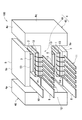
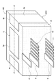
図1および図2に示すのは、本発明にかかる2in1両面放熱半導体パッケージ100(場合によっては4面冷却)の斜視図である。図3に示すのは、図2中に示すA−A’線を含む断面模式図である。ただし、図1では、モールド樹脂部15を除去した形態を示している。
【0020】
このような半導体パッケージ100は、たとえばブラシレスモータ用の三相インバータ回路の一部を構成する。半導体スイッチング素子1,2(以下、単に半導体チップともいう)の種類には、たとえばIGBTやパワーMOSFETを示すことができる。本実施形態では、パワーMOSFETを例示している。
【0021】
図1および図2に示すように、半導体パッケージ100は、厚さ方向の上下に平行配置された1対の半導体チップ1,2と、中点電極をなすH形状の中継部材4と、半導体チップ1,2の各々に対し、中継部材4の素子搭載部41とは反対側に配置された放熱部材3,5とを互いに組付けて一体化したものである。中継部材4は、半導体チップ1,2が直接または導体ブロック6を介して接合される素子搭載部41と、該素子搭載部41に隣接する放熱部42,42とから構成されている。この中継部材4は、素子搭載部41が半導体チップ1,2より取得した熱を、放熱部42,42より半導体パッケージ100の外部に放出させることが可能である。以下、詳しく説明する。
【0022】
薄板状の半導体チップ1,2は、互いに等価な回路構成を有し、一方の主面側にゲートとソース(IGBTの場合はエミッタ)が露出し、他方の主面側にドレイン(IGBTの場合はコレクタ)が露出するように構成されている。インバータ回路の上相をなす上相半導体チップ1と放熱部材3とは、半田や銀ロウなどの接合材13により直接接合されおり、上相半導体チップ1のドレインと放熱部材3とが導通して同電位となっている。また、上相半導体チップ1と、中継部材4の素子搭載部41とは、導体ブロック6を介して接合材13,13により接合されており、上相半導体チップ1のソースと中継部材4とが導通して同電位となっている。
【0023】
インバータ回路の下相をなす下相半導体チップ2と放熱部材5とは、導体ブロック7を介して接合材13,13により接合され、下相半導体チップ2のソースと放熱部材5とが導通して同電位となっている。また、下相半導体チップ2と、中継部材4の素子搭載部41とは、接合材13により直接接合されており、下相半導体チップ2のドレインと中継部材4とが導通して同電位となっている。
【0024】
また、半導体パッケージ100には、一端がモールド樹脂部15に埋設されて半導体チップ1,2のゲート等の電極に導通し、他端がモールド樹脂部15の外側に引き出される制御信号リード端子群11,12(または端子)が設けられている。個々の制御信号リード端子は、ボンディングワイヤ14により半導体チップ1,2に接続されている。制御信号リード端子群11,12は、たとえばゲート制御リード端子、温度検出リード端子(アノード側とカソード側を含む)、電流検出リード端子、電位検出リード端子などを含む。
【0025】
各半導体チップ1,2に専用の放熱部材3,5は、それぞれ扁平状または板状の形態をなす。放熱部材3,5は、モールド樹脂部15の外側に露出し、互いに略平行な放熱面3p,5pを有する。各放熱部材3,5は、熱伝導性および電気伝導性の観点から、たとえばCu、W、MoおよびAlのグループから選択される1種の金属材料、もしくはそれらの金属材料を主体とする合金により構成されることが好ましい。なお、中継部材4および導体ブロック6,7についても、放熱部材3,5と同様の材料にて構成するとよい。
【0026】
なお、樹脂バリの発生により、外観上、放熱部材3,5の放熱面3p,5pがモールド樹脂部15に埋没する場合がある。その場合には、研削などの加工により、放熱面3p,5pをモールド樹脂部15から露出させるとよい。これについては、以下に説明する中継部材4の、第一放熱面4pおよび第二放熱面4qについても同様のことが言える。
【0027】
上相半導体チップ1側の放熱部材3には、電源正極に接続されるP側電極リード端子8が一体に取り付けられている。下相半導体チップ2側の放熱部材5には、電源負極に接続されるN側電極リード端子10が一体に取り付けられている。中継部材4には、中点電極リード端子9が一体に取り付けられている。P側電極リード端子8、N側電極リード端子10および中点電極リード端子9は、モールド樹脂部15の外側に延出している。
【0028】
本実施形態においては、上記した電流経路用の各リード端子8,9,10と、制御信号リード端子群11,12とを同一方向に引き出すようにして、製造時の利便性を図っている(詳細は後述)。ただし、電流経路用のリード端子8,9,10と、制御信号リード端子群11,12とを180°反対側方向、もしくは90°の角度で交差する方向に引き出すことも不可能ではない。
【0029】
モールド樹脂部15は、半導体チップ1,2の周側面を被覆するとともに、中継部材4および放熱部材3,5により形成される空間を充填している。モールド樹脂部15は、たとえばエポキシ樹脂により構成されるものであり、半導体パッケージ100を構成する各部品を接合材13で接合した後に、インサート成形法等の樹脂成形方法により形成される。
【0030】
上相半導体チップ1と、下相半導体チップ2との中点電極(具体的にはインバータ回路の中点電極)をなす中継部材4は、素子搭載部41と放熱部42,42とから構成されている。素子搭載部41が受けた熱は、放熱部42,42に伝達されて、半導体パッケージ100の外部に放出される。これにより、上相半導体チップ1のソース露出面と、下相半導体チップ2のドレイン露出面との冷却が可能となる。
【0031】
素子搭載部41には、中点電極リード端子9が一体に取り付けられている。中点電極リード端子9は、モータ等の負荷に接続されるものである。放熱部42,42は、素子搭載部41の両側に位置している。素子搭載部41と、放熱部42,42とは鋳造等の金属成形法により一体成形される。そのため、両者の間の熱伝達性は良好である。
【0032】
半導体チップ1,2の厚さ方向を上下方向と定義する。放熱部42,42は、中継部材4のうち、上下方向において、素子搭載部41よりも厚肉に形成された部分を構成している。素子搭載部41には、半導体チップ1,2の制御信号リード端子群11,12、P側電極リード端子8、中点電極リード端子9およびN側電極リード端子10の、モールド樹脂部15の外側への引き出し方向に直交する方向の両側に放熱部42,42が位置する形となっている。これは、放熱部42,42の形成により、リードの引き出しが邪魔されない構造である。
【0033】
図2に示すように、放熱部42,42は、モールド樹脂部15の外側に露出する放熱面4p,4qを形成している。放熱部42,42が形成する放熱面は、放熱部材3,5の放熱面3p,5pと略平行な第一放熱面4pと、該第一放熱面4pに隣接する第二放熱面4qとを含む。本実施形態の半導体パッケージ100においては、第一放熱面4pと、第二放熱面4qとが互いに略直交している。モールド樹脂部15成形用の金型に対する微小な抜き角度を、上記第二放熱面4pに付与してもよい(略直交とする理由の1つ)。
【0034】
図1〜図3に示す半導体パッケージ100においては、各半導体チップ1,2に専用の放熱部材3,5と、放熱部42,42が形成する複数(半導体パッケージ100では4面)の第一放熱面4pとが、上下方向において互いに重ならない位置関係となっている。具体的には、図3から明らかなように、各放熱部材3,5の放熱面3p,5pと、中継部材4の1対の放熱部42,42に2面ずつ形成される第一放熱面4p,4pとは面一である。これにより、放熱部材3,5の放熱面3p,5pを冷却する冷却器と、中継部材4の第一放熱面4p,4pを冷却する冷却器との兼用が容易である。また、半田リフローに先立って行なうべき、放熱部材3,5と中継部材4との組付けおよび治具固定を、中継部材4の第一放熱面4p,4pを基準に行なえる。したがって、半田リフロー後における、放熱部材3、放熱部材5および中継部材4の、3者の組付け精度を高くできる。放熱部材3,5の放熱面3p,5pの平行精度が高いと、図示しない冷却器との密着性も良好となり、高冷却効率を期待できる。
【0035】
図3に示すように、半導体パッケージ100を構成する中継部材4は、放熱部42,42を含む上下方向に関する断面でH形状を呈している。具体的には、放熱部42,42の第一放熱面4pと、第二放熱面4qとが略垂直に交わり、さらに、素子搭載部41の上下面41r,41rと、放熱部42,42の内側面42r,42rとにより、半導体チップ1,2の収容凹所が形成されている。この凹所の深さは、半導体チップ1、放熱部材3、導体ブロック6および3層の接合部13の合計厚さに等しく調整される。
【0036】
また、図3に示すように、素子搭載部41の厚さは一定とされ、その厚さd1は、各放熱部材3,5の厚さd2よりも大となるように調整されている。これにより、半導体チップ1,2から素子搭載部41に付与された熱が、効率良く放熱部42,42に伝達される。
【0037】
なお、図5の断面模式図に示す半導体パッケージ102の中継部材4bも、H形状の概念に含まれる。すなわち、上下方向に関する素子搭載部43の厚さを一定とし、第一放熱面4pおよび第二放熱面4qを有する放熱部44,44の、上下方向に関する厚さが連続的に変化していてもよい。場合によっては、その方が(図5の形態)、素子搭載部43の上下面43r,43rと、放熱部44,44の内側面44r,44rとにより形成された収容凹所への、モールド樹脂の流れ込み性の良化を期待できる。
【0038】
また、図4の断面模式図に示す半導体パッケージ101も、好適な実施形態の1つとして示せる。半導体パッケージ101は、断面T字形状を呈する中継部材4aを備えている。図1〜図3に示した中継部材4のうち、一方の放熱部42を省略した形態が、図4に示す中継部材4aである。断面T字形状の中継部材4aによれば、断面H形状の中継部材4に比べ、冷却効率は若干低下するものの、以下に示す利点が得られる。すなわち、中継部材4aのうち、素子搭載部41の一方の端に放熱部42を設け、その放熱部42が設けられた側とは180°反対側から、制御信号リード端子11,12、P側電極リード端子8(図示せず)、中点電極リード端子9(図示せず)およびN側電極リード端子10をモールド樹脂部15の外側に引き出すことができる。もちろん、半導体パッケージ102自体もコンパクトである。
【0039】
なお、図1〜図5に示す半導体パッケージ100,101,102のいずれについても、上相半導体チップ1が、下相半導体チップ2の真下(または真上)に位置する配置が採用されている。つまり、両半導体チップ1,2が上下方向において並進対称である。この配置は、中継部材4,4a,4bの持つインダクタ成分をできる限り小さくするという観点において有利である。
【0040】
半導体パッケージ100の組立は、以下の手順にて行なうことができる。図6に示すように、まず、上相半導体チップ1を、放熱部材3に載置する。放熱部材3には、半田接合材13がスクリーン印刷等の方法により形成されている。上相半導体チップ1のゲート等の電極と、上相制御信号リード端子群11とをボンディングワイヤ14で接続する。上相半導体チップ1の上に、半田接合材13を介して導体ブロック6を載置する。その後、半田リフローを行なう。
【0041】
なお、上記の組立工程には、リードフレームを使用した公知の方法を採用するとよい。すなわち、放熱部材3と一体形成されたP側電極リード端子8が、モールド樹脂部15の形成後に切断可能な連結部により上相制御信号リード端子群11と連結されてなる、リードフレームを使用することができる。つまり、P側電極リード端子8と上相制御信号リード端子群11とを同一方向に引き出すのは、リードフレームを用いた製法上の要請でもある。
【0042】
同様の手順にて、下相半導体チップ2と中継部材4とを接合する。そして、図7に示すように、上相半導体チップ1と、下相半導体チップ2とを位置決めおよび治具固定して、導体ブロック6と中継部材4、導体ブロック7と放熱部材5とを半田接合する。その後、インサート成形法等によりモールド樹脂部15を形成し、各リード端子同士を分離させることにより、図2に示す半導体パッケージ100が得られる。
【図面の簡単な説明】
【図1】本発明の半導体パッケージの斜視図(モールド樹脂部無し)。
【図2】本発明の半導体パッケージの斜視図(モールド樹脂部有り)。
【図3】本発明の半導体パッケージの断面模式図。
【図4】半導体パッケージの好適な別形態を示す断面模式図。
【図5】半導体パッケージの好適な別形態を示す断面模式図。
【図6】図1の半導体パッケージの組立手順を示す分解斜視図。
【図7】図6に続く半導体パッケージの分解斜視図。
【符号の説明】
1 半導体スイッチング素子(上相)
2 半導体スイッチング素子(下相)
3,5 放熱部材
3p,5p 放熱部材の放熱面
4,4a,4b 中継部材
4p 第一放熱面
4q 第二放熱面
6,7 導体ブロック(スペーサ)
11 上相制御信号リード端子群
12 下相制御信号リード端子群
15 モールド樹脂部
41,43 素子搭載部
42,44 放熱部
100,101,102 半導体パッケージ(半導体装置)[0001]
BACKGROUND OF THE INVENTION
The present invention relates to a semiconductor device.
[0002]
[Prior art]
In a semiconductor power device used in an inverter circuit for driving a motor, a heat radiating member (heat sink) is also provided on the surface (emitter surface in IGBT) side to which a bonding wire is connected in order to improve heat radiating performance. A molded power element package has been devised. Taking an IGBT (Insulated Gate Bipolar Transistor) as a typical power element as an example, the emitter and collector exposed on the upper and lower surfaces of the power element are arranged above and below the power element (hereinafter also referred to as a semiconductor switching element). Soldered to the heat sink directly or via a spacer. The heat sink in this case also has a function as a large current path. On the other hand, the gate (control electrode) of the power element and the control signal lead terminal extending out of the mold resin are conductively connected by a bonding wire.
[0003]
When configuring an inverter circuit, an upper phase switching element and a lower phase switching element are connected in series. For this reason, it has been proposed that resin molding is performed in advance in series rather than individually molding each switching element individually. That is,
[0004]
If attention is paid to the reduction of the inductor component, it is better to bring the upper phase switching element and the lower phase switching element as close as possible. That is, the following
[0005]
[Patent Document 1]
JP 2001-308263 A [Patent Document 2]
JP-A-2002-26251 [0006]
[Problems to be solved by the invention]
Certainly, according to the structure described in
[0007]
An object of the present invention is to provide a semiconductor device that achieves both low surge voltage and high heat dissipation.
[0008]
[Means for solving the problems and actions / effects]
In order to solve the above-described problems, a semiconductor device according to a first aspect of the present invention includes a pair of plate-like semiconductor switching elements arranged in parallel at a predetermined interval in the thickness direction, and a midpoint of these semiconductor switching elements. a relay member having an electrode, against each of the semiconductor switching element, comprising: a heat radiating member arranged on the opposite side of the relay member, and a mold resin portion filling the between their heat radiating member and the relay member, the semiconductor When the thickness direction of the switching element is the vertical direction, the relay member is provided adjacent to each of the element mounting parts directly or indirectly joined to each of the semiconductor switching elements arranged above and below, seen including a heat radiating portion which is formed thicker than the element mounting portion in the vertical direction, the each of the heat radiating member has a substantially parallel radiating surfaces to each other, the heat radiating portion of the relay member, the heat dissipation Forming a first heat dissipating surface substantially parallel to each heat dissipating surface of the material and a second heat dissipating surface adjacent to the first heat dissipating surface, the heat dissipating surface of the heat dissipating member, and the first heat dissipating surface of the relay member And are adjusted to be flush with each other.
[0009]
In the semiconductor device of the present invention, two semiconductor switching elements are stacked vertically via a relay member, and heat dissipating members are further arranged on the upper and lower sides. The pair of heat radiating members are, for example, plate-like metal members, and can also be used as current paths. The relay member inserted between the switching elements forms a middle point electrode. Since the semiconductor switching elements are vertically stacked, the inductor component of the relay member can be reduced. This relay member was buried in the mold resin portion and had no cooling function in the conventional vertically stacked structure (see Patent Document 2). However, in the semiconductor device of the present invention, a heat dissipation portion that is thicker in the vertical direction than the element mounting portion to which the semiconductor switching element is bonded is provided adjacent to the element mounting portion. Therefore, if at least a part of the heat radiation part is exposed from the mold resin part, a heat radiation path of semiconductor switching element → element mounting part → heat radiation part → outside air (or cooler) can be secured, and the relay member itself has a cooling function. Can be expected enough.
[0010]
In a preferred embodiment, each of the heat radiating members has a heat radiating surface substantially parallel to each other, and the heat radiating portion of the relay member is formed on a first heat radiating surface substantially parallel to each heat radiating surface of the heat radiating member, and on the first heat radiating surface. An adjacent second heat radiating surface is formed. Thus, if the heat dissipation surface of the relay member is parallel to the heat dissipation surface of the heat dissipation member disposed above or below each semiconductor switching element, it is possible to cool those heat dissipation surfaces from the same direction. . That is, it is advantageous when a cooler is arranged.
[0011]
Specifically, in the preferred embodiment, the heat radiating portion is formed integrally with the element mounting portion, and forms the first heat radiating surface at a position where it does not overlap any of the heat radiating members in the vertical direction. . By integrating the element mounting portion and the heat radiating portion, the thermal resistance can be made as small as possible. In addition, since the first heat dissipation surface formed by the heat dissipation portion does not overlap the heat dissipation member dedicated to each semiconductor switching element in the vertical direction, the mold resin portion should be formed so that the first heat dissipation surface is exposed. Can also be done relatively easily.
[0012]
More preferably, the heat radiating surface of the heat radiating member and the first heat radiating surface of the relay member are configured to be flush with each other. According to this, it becomes easier to cool both the heat radiation surfaces from the same direction.
[0013]
Further, in manufacturing the semiconductor device of the present invention, the joining between the semiconductor switching element and the relay member and the joining between the semiconductor switching element and the heat radiating member are performed by fixing each component with a jig. When the heat radiating surface of the heat radiating member and the first heat radiating surface of the relay member are flush with each other, the assembly of the heat radiating member and the relay member and fixing of the jig can be performed easily and with high accuracy based on the first heat radiating surface. It can be done. As a result, for example, it is possible to expect an improvement in the assembling accuracy of the parts constituting the semiconductor device after solder reflow or after resin molding. Further, when the heat radiating members are paralleled with high accuracy, the adhesion between the heat radiating members and the cooler is increased, and the cooling efficiency is also increased.
[0014]
Also, the semiconductor device of the present invention is provided with a control signal lead terminal having one end embedded in the mold resin portion and conducting to the control electrode of the semiconductor switching element, and the other end drawn out of the mold resin portion. The element mounting portion of the relay member can be adjacent to the heat radiating portion on both sides in a direction substantially orthogonal to the direction in which the control signal lead terminal is pulled out. If it does in this way, the area of a heat sink can be simply doubled compared with the case where a heat sink is provided only on one side. In addition, it is not overlooked that cooling from all sides is possible.
[0015]
Moreover, the relay member is good to be comprised so that it may exhibit H shape in the cross section regarding an up-down direction. That is, since a pair of semiconductor switching elements can be accommodated in two recesses based on the alphabet “H”, the H shape can be said to be a very convenient shape.
[0016]
Further, the relay member may be configured such that the first heat radiating surface and the second heat radiating surface of the heat radiating portion intersect substantially perpendicularly. And the accommodation recess of a semiconductor switching element is formed by the upper and lower surfaces of an element mounting part, and the inner surface of a thermal radiation part. According to such a configuration, the mold resin part is easily molded. In addition, the inclination about the extraction angle required between the molding dies is included substantially vertically.
[0017]
A semiconductor device according to a second aspect of the present invention includes a pair of plate-like semiconductor switching elements arranged in parallel at a predetermined interval in the thickness direction, and a relay member forming a midpoint electrode of the semiconductor switching elements Each of the semiconductor switching elements includes a heat dissipating member disposed on the opposite side of the relay member, and a mold resin portion filling between the heat dissipating member and the relay member. When the thickness direction is the vertical direction, the relay member is provided adjacent to the element mounting portion, directly or indirectly joined to each of the semiconductor switching elements disposed above and below, A heat dissipating part formed thicker than the element mounting part in the vertical direction, and the element mounting part of the relay member is thicker than the heat dissipating member in the vertical direction. And characterized in that. According to this configuration, heat generated in the semiconductor switching element can be quickly transmitted to the heat radiating unit.
[0018]
One semiconductor switching element is positioned directly above or below the other semiconductor switching element in the vertical direction. According to this arrangement, the distance between the semiconductor switching elements can be minimized, that is, the inductor component of the relay member can be made as small as possible.
[0019]
DETAILED DESCRIPTION OF THE INVENTION
Hereinafter, embodiments of the present invention will be described with reference to the accompanying drawings.
FIG. 1 and FIG. 2 are perspective views of a 2-in-1 double-sided heat radiation semiconductor package 100 (sometimes four-sided cooling) according to the present invention. FIG. 3 is a schematic cross-sectional view including the AA ′ line shown in FIG. However, in FIG. 1, the form which removed the
[0020]
Such a
[0021]
As shown in FIG. 1 and FIG. 2, a
[0022]
The thin-
[0023]
The lower
[0024]
Further, in the
[0025]
The
[0026]
In addition, due to the occurrence of resin burrs, the heat radiation surfaces 3p and 5p of the
[0027]
A P-side
[0028]
In the present embodiment, the
[0029]
The
[0030]
The
[0031]
The midpoint
[0032]
The thickness direction of the
[0033]
As shown in FIG. 2, the
[0034]
In the
[0035]
As shown in FIG. 3, the
[0036]
Further, as shown in FIG. 3, the thickness of the
[0037]
The
[0038]
Also, the
[0039]
In any of the semiconductor packages 100, 101, and 102 shown in FIGS. 1 to 5, an arrangement is employed in which the upper
[0040]
The assembly of the
[0041]
In addition, it is good to employ | adopt the well-known method using a lead frame for said assembly process. That is, a lead frame is used in which the P-side
[0042]
The lower
[Brief description of the drawings]
FIG. 1 is a perspective view of a semiconductor package of the present invention (without a mold resin portion).
FIG. 2 is a perspective view of the semiconductor package of the present invention (with a mold resin portion).
FIG. 3 is a schematic cross-sectional view of a semiconductor package of the present invention.
FIG. 4 is a schematic cross-sectional view showing another preferred embodiment of a semiconductor package.
FIG. 5 is a schematic cross-sectional view showing another preferred embodiment of a semiconductor package.
6 is an exploded perspective view showing an assembling procedure of the semiconductor package of FIG. 1;
7 is an exploded perspective view of the semiconductor package following FIG. 6. FIG.
[Explanation of symbols]
1 Semiconductor switching element (upper phase)
2 Semiconductor switching element (lower phase)
3, 5
DESCRIPTION OF
Claims (8)
前記半導体スイッチング素子の厚さ方向を上下方向としたとき、
前記中継部材は、上下に配置された前記半導体スイッチング素子の各々に直接または間接接合された素子搭載部と、該素子搭載部に隣接して設けられ、前記上下方向に関して前記素子搭載部よりも厚肉に形成された放熱部と、を含み、
前記放熱部材の各々は、互いに略平行な放熱面を有し、前記中継部材の前記放熱部は、前記放熱部材の各放熱面と略平行な第一放熱面と、該第一放熱面に隣接する第二放熱面とを形成し、
前記放熱部材が有する放熱面と、前記中継部材の前記第一放熱面とが面一となるように調整されていることを特徴とする半導体装置。A pair of plate-like semiconductor switching elements arranged in parallel at a predetermined interval in the thickness direction, a relay member forming a middle point electrode of the semiconductor switching elements, and for each of the semiconductor switching elements, A heat dissipating member disposed on the opposite side of the relay member, and a mold resin portion filling between the heat dissipating member and the relay member,
When the thickness direction of the semiconductor switching element is the vertical direction,
The relay member is provided adjacent to the element mounting portion, which is directly or indirectly joined to each of the semiconductor switching elements disposed above and below, and is thicker than the element mounting portion in the vertical direction. and the heat radiating portion which is formed in the flesh, only including,
Each of the heat radiating members has a heat radiating surface substantially parallel to each other, and the heat radiating portion of the relay member is adjacent to the first heat radiating surface substantially parallel to each heat radiating surface of the heat radiating member, and the first heat radiating surface. Forming a second heat dissipation surface ,
A semiconductor device , wherein the heat dissipation surface of the heat dissipation member and the first heat dissipation surface of the relay member are adjusted to be flush with each other .
前記中継部材の前記素子搭載部には、前記制御信号リード端子の引き出し方向と略直交する方向の両側に前記放熱部が隣接している請求項1又は2に記載の半導体装置。One end is embedded in the mold resin portion and is connected to the control electrode of the semiconductor switching element, and the other end is provided with a control signal lead terminal that is drawn out of the mold resin portion,
3. The semiconductor device according to claim 1, wherein the heat dissipating part is adjacent to the element mounting part of the relay member on both sides in a direction substantially orthogonal to a direction in which the control signal lead terminal is pulled out.
前記半導体スイッチング素子の厚さ方向を上下方向としたとき、
前記中継部材は、上下に配置された前記半導体スイッチング素子の各々に直接または間接接合された素子搭載部と、該素子搭載部に隣接して設けられ、前記上下方向に関して前記素子搭載部よりも厚肉に形成された放熱部と、を含み、
前記上下方向に関し、前記中継部材の前記素子搭載部は、前記放熱部材よりも厚肉であることを特徴とする半導体装置。 A pair of plate-like semiconductor switching elements arranged in parallel at a predetermined interval in the thickness direction, a relay member forming a middle point electrode of the semiconductor switching elements, and for each of the semiconductor switching elements, A heat dissipating member disposed on the opposite side of the relay member, and a mold resin portion filling between the heat dissipating member and the relay member,
When the thickness direction of the semiconductor switching element is the vertical direction,
The relay member is provided adjacent to the element mounting portion, which is directly or indirectly joined to each of the semiconductor switching elements disposed above and below, and is thicker than the element mounting portion in the vertical direction. Including a heat dissipating part formed on the meat,
In the vertical direction, the element mounting portion of the relay member is thicker than the heat dissipation member .
Priority Applications (1)
| Application Number | Priority Date | Filing Date | Title |
|---|---|---|---|
| JP2003085504A JP4019989B2 (en) | 2003-03-26 | 2003-03-26 | Semiconductor device |
Applications Claiming Priority (1)
| Application Number | Priority Date | Filing Date | Title |
|---|---|---|---|
| JP2003085504A JP4019989B2 (en) | 2003-03-26 | 2003-03-26 | Semiconductor device |
Publications (2)
| Publication Number | Publication Date |
|---|---|
| JP2004296663A JP2004296663A (en) | 2004-10-21 |
| JP4019989B2 true JP4019989B2 (en) | 2007-12-12 |
Family
ID=33400412
Family Applications (1)
| Application Number | Title | Priority Date | Filing Date |
|---|---|---|---|
| JP2003085504A Expired - Fee Related JP4019989B2 (en) | 2003-03-26 | 2003-03-26 | Semiconductor device |
Country Status (1)
| Country | Link |
|---|---|
| JP (1) | JP4019989B2 (en) |
Families Citing this family (20)
| Publication number | Priority date | Publication date | Assignee | Title |
|---|---|---|---|---|
| JP4522271B2 (en) * | 2005-01-20 | 2010-08-11 | 富士通株式会社 | Electronic device and heat sink assembly used therefor |
| JP4979909B2 (en) | 2005-08-19 | 2012-07-18 | 株式会社日立製作所 | Power converter |
| US8094034B2 (en) | 2007-09-18 | 2012-01-10 | Georgia Tech Research Corporation | Detecting actuation of electrical devices using electrical noise over a power line |
| JP5217015B2 (en) * | 2008-01-16 | 2013-06-19 | 日産自動車株式会社 | Power converter and manufacturing method thereof |
| JP5125530B2 (en) * | 2008-01-16 | 2013-01-23 | 日産自動車株式会社 | Power converter |
| JP4937951B2 (en) * | 2008-03-25 | 2012-05-23 | 三菱電機株式会社 | Power semiconductor device and manufacturing method thereof |
| JP2009283656A (en) | 2008-05-22 | 2009-12-03 | Denso Corp | Semiconductor device and manufacturing method thereof |
| WO2009150875A1 (en) * | 2008-06-12 | 2009-12-17 | 株式会社安川電機 | Power module and control method therefore |
| JP5268660B2 (en) * | 2009-01-08 | 2013-08-21 | 三菱電機株式会社 | Power module and power semiconductor device |
| US9766277B2 (en) | 2009-09-25 | 2017-09-19 | Belkin International, Inc. | Self-calibrating contactless power consumption sensing |
| US8805628B2 (en) | 2009-09-25 | 2014-08-12 | Belkin International, Inc. | Systems and methods for measuring electrical power usage in a structure and systems and methods of calibrating the same |
| JP5213884B2 (en) | 2010-01-27 | 2013-06-19 | 三菱電機株式会社 | Semiconductor device module |
| JP5242629B2 (en) * | 2010-05-10 | 2013-07-24 | 株式会社東芝 | Power semiconductor device |
| US9291694B2 (en) | 2010-07-02 | 2016-03-22 | Belkin International, Inc. | System and method for monitoring electrical power usage in an electrical power infrastructure of a building |
| JP5440427B2 (en) * | 2010-07-09 | 2014-03-12 | 株式会社デンソー | Semiconductor device and manufacturing method thereof |
| JP2013258387A (en) * | 2012-05-15 | 2013-12-26 | Rohm Co Ltd | Power-module semiconductor device |
| JP5444486B2 (en) * | 2013-02-15 | 2014-03-19 | 株式会社東芝 | Inverter device |
| US9978670B2 (en) | 2014-11-27 | 2018-05-22 | Mitsubishi Electric Corporation | Semiconductor module and semiconductor driving device |
| WO2018150449A1 (en) * | 2017-02-14 | 2018-08-23 | 日本精工株式会社 | Semiconductor module and production method therefor, drive device equipped with semiconductor module, and electric power steering device |
| FR3073978B1 (en) * | 2017-11-17 | 2022-10-28 | Inst Vedecom | POWER ELECTRONIC MODULE AND ELECTRONIC SYSTEM COMPRISING SUCH AN ELECTRONIC MODULE |
-
2003
- 2003-03-26 JP JP2003085504A patent/JP4019989B2/en not_active Expired - Fee Related
Also Published As
| Publication number | Publication date |
|---|---|
| JP2004296663A (en) | 2004-10-21 |
Similar Documents
| Publication | Publication Date | Title |
|---|---|---|
| JP4019989B2 (en) | Semiconductor device | |
| US9035453B2 (en) | Semiconductor device | |
| JP4239580B2 (en) | Semiconductor device | |
| US8497572B2 (en) | Semiconductor module and method of manufacturing the same | |
| JP3516789B2 (en) | Semiconductor power module | |
| US10811345B2 (en) | Semiconductor device and method of manufacturing the same | |
| US8610263B2 (en) | Semiconductor device module | |
| JP7159620B2 (en) | Semiconductor devices, cooling modules, power converters and electric vehicles | |
| JP2001308263A (en) | Semiconductor switching module and semiconductor device using it | |
| JP2000164800A (en) | Semiconductor module | |
| CN108933124B (en) | electronic device | |
| JP2015095560A (en) | Power module | |
| US11195775B2 (en) | Semiconductor module, semiconductor device, and manufacturing method of semiconductor module | |
| US11315850B2 (en) | Semiconductor device | |
| JP2002095267A (en) | Inverter device | |
| US10950526B2 (en) | Semiconductor device | |
| JP7313413B2 (en) | semiconductor equipment | |
| US11145578B2 (en) | Semiconductor package with top or bottom side cooling and method for manufacturing the semiconductor package | |
| JP2005116875A (en) | Semiconductor device | |
| JP5277806B2 (en) | Semiconductor device | |
| JP2010177453A (en) | Semiconductor device | |
| CN112447691A (en) | Semiconductor device and method for manufacturing semiconductor device | |
| JP2004048084A (en) | Semiconductor power module | |
| JP2005150419A (en) | Semiconductor device | |
| WO2024024067A1 (en) | Electric power conversion device, and method for producing electric power conversion device |
Legal Events
| Date | Code | Title | Description |
|---|---|---|---|
| A621 | Written request for application examination |
Free format text: JAPANESE INTERMEDIATE CODE: A621 Effective date: 20050517 |
|
| A977 | Report on retrieval |
Free format text: JAPANESE INTERMEDIATE CODE: A971007 Effective date: 20060703 |
|
| A131 | Notification of reasons for refusal |
Free format text: JAPANESE INTERMEDIATE CODE: A131 Effective date: 20070313 |
|
| A521 | Written amendment |
Free format text: JAPANESE INTERMEDIATE CODE: A523 Effective date: 20070501 |
|
| TRDD | Decision of grant or rejection written | ||
| A01 | Written decision to grant a patent or to grant a registration (utility model) |
Free format text: JAPANESE INTERMEDIATE CODE: A01 Effective date: 20070904 |
|
| A61 | First payment of annual fees (during grant procedure) |
Free format text: JAPANESE INTERMEDIATE CODE: A61 Effective date: 20070917 |
|
| FPAY | Renewal fee payment (event date is renewal date of database) |
Free format text: PAYMENT UNTIL: 20101005 Year of fee payment: 3 |
|
| R150 | Certificate of patent or registration of utility model |
Free format text: JAPANESE INTERMEDIATE CODE: R150 |
|
| FPAY | Renewal fee payment (event date is renewal date of database) |
Free format text: PAYMENT UNTIL: 20101005 Year of fee payment: 3 |
|
| FPAY | Renewal fee payment (event date is renewal date of database) |
Free format text: PAYMENT UNTIL: 20111005 Year of fee payment: 4 |
|
| FPAY | Renewal fee payment (event date is renewal date of database) |
Free format text: PAYMENT UNTIL: 20121005 Year of fee payment: 5 |
|
| FPAY | Renewal fee payment (event date is renewal date of database) |
Free format text: PAYMENT UNTIL: 20121005 Year of fee payment: 5 |
|
| FPAY | Renewal fee payment (event date is renewal date of database) |
Free format text: PAYMENT UNTIL: 20131005 Year of fee payment: 6 |
|
| R250 | Receipt of annual fees |
Free format text: JAPANESE INTERMEDIATE CODE: R250 |
|
| R250 | Receipt of annual fees |
Free format text: JAPANESE INTERMEDIATE CODE: R250 |
|
| R250 | Receipt of annual fees |
Free format text: JAPANESE INTERMEDIATE CODE: R250 |
|
| R250 | Receipt of annual fees |
Free format text: JAPANESE INTERMEDIATE CODE: R250 |
|
| LAPS | Cancellation because of no payment of annual fees |