JP4016231B2 - Video signal additional information transmission method, video signal output device, playback device, recording device, and signal conversion device - Google Patents
Video signal additional information transmission method, video signal output device, playback device, recording device, and signal conversion device Download PDFInfo
- Publication number
- JP4016231B2 JP4016231B2 JP31774498A JP31774498A JP4016231B2 JP 4016231 B2 JP4016231 B2 JP 4016231B2 JP 31774498 A JP31774498 A JP 31774498A JP 31774498 A JP31774498 A JP 31774498A JP 4016231 B2 JP4016231 B2 JP 4016231B2
- Authority
- JP
- Japan
- Prior art keywords
- information
- video signal
- signal
- cgms
- additional information
- Prior art date
- Legal status (The legal status is an assumption and is not a legal conclusion. Google has not performed a legal analysis and makes no representation as to the accuracy of the status listed.)
- Expired - Fee Related
Links
Images


Description
【0001】
【発明の属する技術分野】
この発明は、アナログ映像信号についての、例えば複製世代制限のためのCGMS情報などの付加情報の伝送方法およびその伝送方法を適用した映像信号の出力装置、再生装置、記録装置、信号変換装置に関する。
【0002】
【従来の技術】
近年、インターネット、デジタルビデオディスクなどのデジタルコンテンツの普及に伴い、このデジタルコンテンツについての不正な複製(コピー)による著作権侵害が問題となっている。そこで、この問題に対処するため、デジタルコンテンツに複製制御のための情報を付加し、この付加情報を用いて、不正な複製を防止することが考えられている。
【0003】
この複製の防止のための制御としては、情報ソースに応じて、全く複製を認めない場合と、1回は複製を認めるが、1回複製されたものからの複製を禁止する場合(世代制限の複製制御方式)とが考えられている。前者は、例えばDVD−ROMのように、コンテンツメーカが作成して販売するオリジナルソフトの場合である。後者の世代制限の複製制御方式は、例えば放送メディアにおいて、放送される情報の場合などに適用される。
【0004】
後者の世代制限の複製制御方式の場合には、有効に複製世代の制御ができる方式が望まれている。この複製世代の管理が行える複製制御情報の方式としては、CGMS(Copy Generation Management System;コピー・ジェネレーション・マネージメント・システム)方式が提案されている。
【0005】
このCGMS方式は、アナログ映像信号(CGMS−Aと呼ばれる)であれば、その輝度信号の垂直ブランキング期間内の特定の1水平区間、例えばNTSC信号の場合には、第20水平区間の有効映像部分に重畳する20ビットの付加情報のうちの2ビットを複製制御用の情報として重畳し、また、デジタル映像信号(CGMS−Dと呼ばれる)であれば、デジタル映像データに挿入付加する付加情報として、複製制御用の2ビットの情報を含めて伝送する方式である。
【0006】
アナログ映像信号の垂直ブランキング期間の、例えば第20水平区間の前記20ビットの付加情報の先頭の2ビット(ワード0)にはアスペクト比の情報などが重畳される。次の4ビット(ワード1)はヘッダであり、この4ビットが「0000」のとき、次の8ビット(ワード2)は複製制御信号であることを示す。最後の6ビットはCRCC(エラー検出コード)である。
【0007】
CGMS−Aの情報は、ワード2の先頭の2ビット(20ビットの付加情報の第7ビットおよび第8ビット)の2ビットである。このCGMS−Aの複製制御用の2ビットの情報(以下、CGMS−A情報という)の意味内容は、
[00]……複製可能
[10]……1回複製可能(1世代だけ複製可能)
[11]……複製禁止(絶対複製禁止)
である。
【0008】
映像情報に付加されたCGMS−A情報が[10]であった場合に、CGMS方式対応の記録装置では、その映像情報の複製記録が可能であると判断して記録を実行するが、記録された映像信号には[11]に書き換えられたCGMS−A情報が付加される。そして、記録しようとする映像情報に付加されたCGMS−A情報が[11]の場合には、CGMS対応の記録装置では、その映像信号の複製記録は禁止であるとして記録の実行が禁止される。
【0009】
なお、ワード2の第3ビット目および第4ビット目(20ビットの付加情報の第9ビットおよび第10ビット)には、APS(アナログ・プロテクション・システム)情報が定義される。これは、アナログ映像信号についての複製を防止するための、AGC制御用の疑似同期パルスの挿入制御と、カラーストライプ用の反転バーストの制御を行うためのものである。
【0010】
このCGMS−A方式は、規格化されており、NTSC信号においては、デジタル機器間のアナログ接続時の複製制御信号として実際に使用されている。
【0011】
なお、525Pの映像信号、すなわち、走査線数525本、60フレーム方式の順次走査信号の場合には、その輝度信号の垂直ブランキング期間の第41水平区間の有効映像部分に、上述したものと同じ20ビットの付加情報が重畳されることが規格として設定されているが、録画機器が525P対応のものが現在は存在しないので、規格が存在するだけである。ハイビジョン信号について、このCGMS−A方式をどのように適用するかは、まだ、規格すら定まっていない。
【0012】
【発明が解決しようとする課題】
上述したように、CGMS−A情報は、従来は、垂直ブランキング期間の特定の1水平区間(NTSC信号の場合には、第20水平区間)に重畳される複数ビットの付加情報の一部として伝送されている。このため、例えばNTSC信号の場合には、付加情報が重畳されている第20水平区間の情報を抽出し、そのうちの2ビットの複製制御用の情報部分を書き替えるだけで、複製が禁止されていた映像情報の複製を可能なように改ざんすることが可能であり、改ざんが比較的容易であると言う問題がある。
【0013】
また、現行のCGMS−A情報の伝送に関する方式は、NTSC信号および、いわゆる525P(走査線数が525本の順次走査方式)の映像信号について定められているだけであり、それ以上の解像度のハイビジョン信号に関しては、どのようにしてCGMS信号を重畳するか、定まった方式が存在しない。
【0014】
この種のハイビジョン信号は、高解像度の信号であるので、不正な複製を防止することができるようにする要求が高くなると考えられる。
【0015】
この発明は、以上の点にかんがみ、アナログ映像信号にCGMS−A情報を重畳する方式として、不正な改ざんがし難く、しかも、ハイビジョン信号にも対応可能な方法を提供することを目的とするものである。
【0016】
【課題を解決するための手段】
上記課題を解決するため、この発明による映像信号の付加情報の伝送方法においては、
映像信号の垂直ブランキング期間内の水平区間であって、垂直同期信号区間よりも前の水平区間または前記垂直同期信号区間よりも後の水平区間の、いずれの水平区間にパルスを挿入するかにより、1ビットの情報を表し、
その1ビットの情報の複数ビットを1パケットとして、付加情報を伝送することを特徴とする。
【0017】
上記の構成のこの発明によれば、垂直ブランキング期間内の1水平区間に複数ビットからなる付加情報が重畳されるのではなく、各垂直ブランキング期間に1ビットの情報が挿入され、それが複数ビット分集められて、1パケットとして付加情報が伝送されるようになる。すなわち、1パケットのデータは、複数フィールド(フレーム)分の区間に渡るものとなっている。そして、その1パケット内に少なくともCGMS−A情報が含められるものである。
【0018】
このように、垂直ブランキング期間内の特定の1水平区間に付加情報を重畳するのではなく、複数フィールドまたは複数フレームに渡る区間に付加情報を重畳するので、付加情報のうちのCGMS−A情報の改ざんが困難になる。また、1水平区間に複数ビットの付加情報のすべてを重畳する場合には、1水平区間は定まった区間であるので、重畳ビット数に制限が生じるが、この発明の場合には、パケットを構成するビット数は、伝送したい付加情報の情報量に合わせて設定することが可能である。このため、伝送できる情報量が、多くなるという効果がある。
【0019】
そして、525P以上の解像度の映像信号についても、容易に適用可能であるという利点もある。
【0020】
【発明の実施の形態】
以下、この発明による映像信号の付加情報の伝送方法の実施の形態を、図を参照しながら説明する。
【0021】
[付加情報の伝送方法の実施の形態]
[第1の実施の形態]
図1は、この発明による映像信号の付加情報の伝送方法の第1の実施の形態を説明するための図であり、これは、NTSC映像信号に、この発明が適用された場合の例である。この実施の形態では、1つの垂直ブランキング期間に1ビットの付加情報を、映像信号に重畳して伝送する。そして、複数個の垂直ブランキング期間によって、複数ビットからなる1パケットの付加情報を、映像信号に重畳して伝送するようにする。
【0022】
図1(A),(B)は、この実施の形態の場合のNTSC映像信号の垂直ブランキング期間内の垂直同期信号の近傍部分の区間の様子を示すものである。この実施の形態においては、垂直同期信号区間の直前、直後のいずれかの区間に、所定のパルス高の1パルスPを重畳することにより、1ビットの付加情報を映像信号に重畳するようにする。
【0023】
例えば、図1(A)に示すように、垂直同期信号区間の直後の水平区間にパルスPが挿入されるときには、重畳される付加情報ビットは“1”とし、また、図1(B)に示すように、垂直同期信号区間の直前の水平区間にパルスPが挿入されるときには、重畳される付加情報ビットは“0”とする。
【0024】
この実施の形態の場合、パルスPは、それぞれ等化パルスの直後のペデスタルレベル区間に白レベル側に挿入される。これは、一般に、テレビ受像機において、ペデスタルクランプが施されるパルス区間に相当している。
【0025】
したがって、垂直ブランキング期間内で、予め設定したスレッショールド値を超えるか否かにより、前記の所定高さのパルスPを検出すると共に、その検出位置の垂直同期信号との前後関係から、1つの垂直ブランキング期間内に1ビットの付加情報を伝送し、検出することができる。
【0026】
このように1つの垂直ブランキング期間に1ビットを伝送し、その複数垂直ブランキング期間で複数ビットを伝送し、そして、その所定数の複数ビットで1パケットを構成する。
【0027】
図1(C)に、1パケットの付加情報のデータ構造の例を示す。すなわち、1パケットの先頭の所定の複数ビット、例えば4ビットをヘッダとし、それに続く、例えば8ビットにCGMS−A情報と、APS情報とを含める。そして、最後に、パケットの終わりを示す例えば8ビットのターミネーターを挿入する。なお、1パケットの大きさ、つまり、1パケットのデータ量が予め定まった値に固定されている場合には、前記のターミネーターは不要である。
【0028】
図1(D)に、CGMS−A情報とAPS情報との組み合わせに対するAGC疑似同期パルスの挿入のオン・オフ制御、ならびに、カラーストライプ用のバースト反転制御に関する対応テーブルを示す。
【0029】
なお、上述の第1の実施の形態の説明においては、1パケットには、CGMS−A情報の他にAPS情報を含めるようにしたが、APS情報は含めなくてもよい。
【0030】
図1は、NTSC映像信号の場合について説明したが、525Pの映像信号の場合においても、同期信号は相似形であるので、第1の実施の形態は、525Pの映像信号に対しても、全く同様に適用できる。
【0031】
[第2の実施の形態]
この第2の実施の形態は、パケット構造が第1の実施の形態と異なる。
【0032】
映像信号の複製世代を制御する方式としては、CGMS方式の他に、電子透かし処理を用いる方法が知られている。
【0033】
電子透かし処理は、映像データに存在する人間の知覚上の重要でない部分、すなわち、映像に対して冗長でない部分に、雑音として情報を埋め込む処理である。このような電子透かし処理により画像データ中に埋め込まれた付加情報は、その画像データから除去されにくい。一方、画像データについてフィルタリング処理やデータ圧縮処理をした後であっても、それらに埋め込まれた付加情報を画像データ中から検出することが可能である。
【0034】
この電子透かし処理を用いる複製制御方式の場合、埋め込む付加情報により、
▲1▼「複製可能(Copy Free)」
▲2▼「1回複製可能(1世代だけ複製可能)(One Copy)」
▲3▼「これ以上の複製禁止(No More Copy)」
▲4▼「絶対複製禁止(Never Copy)」
の4状態を、当該電子透かし情報が重畳された画像データの複製世代や複製制限状態を表すようにしている。
【0035】
▲1▼「複製可能(Copy Free)」は、画像データの自由な複製が可能であることを表す。▲2▼「1回複製可能(1世代だけ複製可能)(One Copy)」は、1回だけ画像データの複製が可能であることを示す。▲3▼「これ以上の複製禁止(No More Copy)」は、▲2▼の1回複製可能の状態の画像データから、当該画像データが複製されたものであって、これ以上の複製は禁止であることを示す。▲4▼「絶対複製禁止(Never Copy)」は、複製は全く禁止であることを示す。
【0036】
電子透かし処理としては、PN(Pseudorandom Noise;疑似雑音符号)系列の符号(以下、PN符号という)を用いて、複製制御情報をスペクトラム拡散し、そのスペクトラム拡散した複製制御情報を電子透かし情報WMとして、画像情報に重畳する方法がある。
【0037】
この方法の場合、電子透かし情報は、映像信号と同じ時間領域、周波数領域に重畳されるため、重畳されている電子透かし情報を完全に消去することが困難である。このため、不正な改ざんがされにくいという顕著な効果がある。
【0038】
しかし、例えば「1回複製可能(1世代だけ複製可能)(One Copy)」から、「これ以上の複製禁止(No More Copy)」の状態に書き換えを行う場合には、前の電子透かし情報が完全に消去されずに残留することになる。そこで、消去せずに、例えば、別系列のPN符号を用いて重ねて重畳して、両方のスペクトラム拡散信号を検出し、複製世代が複製禁止に近い方を選択するなどの方法が考えられている。
【0039】
しかしながら、複数個のスペクトラム拡散信号が映像信号に重畳されると、画面上でそれが目に付きやすくなる問題がある。このため、例えば、1回複製可能とする場合には、電子透かし情報は、「1回複製可能(1世代だけ複製可能)(One Copy)」の状態から書き換えず、垂直ブランキング期間に付加情報としてチケット情報を重畳して伝送し、このチケット情報により、複製が行われたか否かを示すようにすることが考えられている。すなわち、電子透かし情報は、書き換えないが、このチケット情報を書き換える方式である。
【0040】
この第2の実施の形態の場合には、図2に示すように、前記の付加情報としての1パケットの情報の中に、このチケット情報を含めるようにする。すなわち、図2の例では、ヘッダ情報と、CGMS−A/APS情報との間に、チケット情報を挿入するものである。
【0041】
この第2の実施の形態によれば、CGMS情報による映像信号の複製の世代制限制御ができると共に、電子透かし情報による映像信号の複製の世代制限制御が、映像信号の劣化を少なくして実現でき、より強力に不正な複製の発生を防止することができる。すなわち、例えばCGMS情報が改ざんされたとしても、改ざんが非常に困難である電子透かし情報は正しく伝送されていると考えられ、不正な複製を強力に防止することができる。
【0042】
[第3の実施の形態]
前述の実施の形態の図1で示したパルスPの挿入位置は、同期パルスの直後のペデスタルレベル部分であって、この位置は、テレビ受像機では直流再生のためのペデスタルクランプが行われる位置である。そのため、クランプレベルがパルスPのために変動してしまうおそれがある。
【0043】
そこで、この第3の実施の形態では、パルスPの重畳位置を、図3(A)および図3(B)に示すように、ペデスタルクランプが行われるような同期パルスの直後の区間を除く区間となるようにずらすようにしている。
【0044】
この第3の実施の形態の場合のパルスPの検出および付加情報ビットの検出は、第1の実施の形態と同様にして行うことができる。
【0045】
この第3の実施の形態によれば、垂直ブランキング期間内でのパルスPの重畳により、テレビ受像機におけるペデスタルクランプの動作への悪影響を防止することができる。
【0046】
この第3の実施の形態は、NTSC映像信号だけでなく、同期信号の形状が相似形である525Pの映像信号についても適用できることはいうまでもない。
【0047】
[第4の実施の形態]
以上の実施の形態は、NTSCカラー映像信号や525Pの映像信号の場合であったが、525P以上の解像度の映像信号、例えば1080Iなどのハイビジョン信号にも、この発明は適用できる。
【0048】
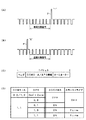
ただし、ハイビジョン信号の同期信号HDは、図4に示すような3値になる。すなわち、ハイビジョン信号の同期パルスHDは、ペデスタルレベルよりも低いレベル側の同期パルス(以下負方向パルスと呼ぶことにする)HDaと、ペデスタルレベルよりも高いレベル側の同期パルスHDb(以下正方向パルスと呼ぶことにする)とからなる。このため、図1に示すような同期信号のバックポーチ部分は正方向パルスHDbと重なり、前述のようなパルスPを重畳することができない。この第4の実施の形態においては、この点を考慮したパルスの重畳方法を提供するものである。
【0049】
図5は、この第4の実施の形態のパルスの重畳方法を示すものである。図5(A)に示す同期信号部分は、同期信号HDの負方向パルスHDaおよび正方向パルスHDbは、そのままのもので、これは1ビットデータの重畳は無い状態である。
【0050】
一方、図5(B)は、1ビットデータを重畳した場合の同期信号部分を示しており、負方向パルスHDaの高さは変わらないが、正方向パルスHDbの高さが変更されて、パルスHDbと区別することができる程度にパルス高の高い正方向パルスHDcとされるものである。
【0051】
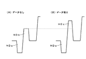
そして、図6(A)に示すように、正方向パルスが、パルスHDbからパルスHDcに変更された同期信号HDが、垂直同期信号の後の水平区間に挿入されている場合には、重畳された1ビットデータは、“1”とされ、また、図6(B)に示すように、正方向パルスが、パルスHDbからパルスHDcに変更された同期信号HDが、垂直同期信号の前の水平区間に挿入されている場合には、重畳された1ビットデータは、“0”とされる。
【0052】
この第4の実施の形態の場合には、パルスHDbの高さと、パルスHDcの高さの中間のレベルのスレッショールド値を用意して、垂直ブランキング期間内で、そのスレッショールド値を超えるパルスをパルスHDcとして検出して、1ビットの重畳データ有りを検出する。そして、そのパルスHDcの垂直ブランキング期間内の検出時点が垂直同期信号の前か、または後かを検出することにより、その検出した1ビットのデータが“1”か、“0”かを検出する。こうして、前述の実施の形態と同様にして、1つの垂直ブランキング期間について1ビットのデータを検出することができる。
【0053】
[第5の実施の形態]
以上の実施の形態は、垂直ブランキング期間内において、挿入されたパルスの垂直同期信号の前後により1ビットの“1”、“0”を表すようにした。これに対して、この第5の実施の形態では、垂直ブランキング期間内の特定の水平区間において、水平同期信号の後のペデスタルレベル部分に、正方向(白レベル方向)のパルスを挿入するのであるが、そのパルスの幅、高さあるいは位置などの属性を変えることにより、1ビットデータの“1”、“0”を表すようにする。
【0054】
図7は、この第5の実施の形態をハイビジョン信号に適用した場合を示すもので、変更する挿入パルスの属性により、実施例1〜実施例3の3つの場合がある。図7において、パルスPhdが挿入されたパルスを示している。
【0055】
図7(A)は、ハイビジョン信号の同期信号HD部分を示したものであるが、これはデータ無しの場合であって、同期信号HDの後のベデスタルレベル部分にパルスPhdは重畳されていない状態である。
【0056】
この第5の実施の形態の実施例1においては、同期パルスHDの後のペデスタルレベル部分に重畳される正方向(白レベル方向)のパルスPhdのパルス幅を変更して、1ビット情報を表現する。
【0057】
すなわち、例えば図7(B)に示すように、実施例1においては、同期信号HDからdだけ後の位置にパルスPhdを重畳するのであるが、そのパルス幅が幅広のW1であるときには、1ビットデータの“1”を表し、そのパルス幅が幅狭のW0であるときには、1ビットデータの“0”を表すように定める。
【0058】
この実施例1の場合には、同期信号HDの直後からdの位置にパルスPhdが存在するか否かを判定して、1ビットデータが重畳されているか否かを判定し、パルスPhdが重畳されているときには、例えば、そのパルス幅が、W0<Wth<W1に設定されているスレッショールド値Wthよりも大きいか否かにより、その重畳1ビットデータの“1”、“0”を判定するようにする。
【0059】
また、この実施例1の場合、図7(B)のように、パルスPhdの高さを、前述のパルスHDcのパルス高のように同期信号HDの正方向パルスHDbよりも高くして、そのパルスHDbよりもパルス高の高いパルスを検出することにより、パルスPhdの有無を検出し、パルスPhdが検出されたら、そのパルス幅を検出するという方法を用いることもできる。
【0060】
なお、この実施例1において、パルスPhdの検出方法として前者の方法を用いる場合には、パルスPhdのパルス高を正方向パルスHDbよりも高くしなくてもよい。
【0061】
次に、この第5の実施の形態の実施例2においては、同期パルスHDの後のペデスタルレベル部分に重畳される正方向(白レベル方向)のパルスPhdのパルス高を変更して、1ビット情報を表現する。
【0062】
すなわち、例えば図7(C)に示すように、この実施例2においては、同期信号HDからdだけ後の位置にパルスPhdを重畳するのであるが、そのパルスの高さが高いH1であるときには、1ビットデータ“1”を表し、そのパルスの高さが低いH0であるときには、1ビットデータ“0”を表すように定める。
【0063】
この実施例2の場合には、例えば、同期信号HDの直後からdの位置にパルスPhdが存在するか否かを判定して、1ビットデータが重畳されているか否かを判定し、パルスPhdが重畳されているときには、例えば、そのパルスの高さが、H0<Hth<H1に設定されているスレッショールド値Hthよりも大きいか否かにより、重畳1ビットデータの“1”、“0”を判定するようにする。
【0064】
さらに、この第5の実施の形態の実施例3においては、同期パルスHDの後のペデスタルレベル部分に重畳される正方向(白レベル方向)のパルスPhdのパルス位置を変更して、1ビット情報を表現する。
【0065】
すなわち、例えば図7(D)に示すように、この実施例3においては、同期信号HDの正方向パルスHDbよりもパルス高の高いパルスPhdが、同期信号HDから遠い距離d1の位置に重畳されているときには、1ビットデータ“1”を表し、同期信号HDから近い距離d0の位置に重畳されているときには、1ビットデータ“0”を表すように定める。
【0066】
この実施例3の場合には、例えば、パルスHDbよりもパルス高の高いパルスを検出することにより、パルスPhdの有無を検出して1ビットデータが重畳されているか否かを判定し、パルスPhdが検出されたら、その同期信号HDに対するパルス位置を検出することにより、重畳1ビットデータの“1”、“0”を判定するようにする。
【0067】
以上のようにして、この第5の実施の形態によれば、同期信号HDの後に重畳されるパルスPhdの属性を利用することにより、1ビットの情報の伝送が可能になり、その複数ビットからなるパケットの情報として、前述した第1の実施の形態や第2の実施の形態と同様にして、CGMS−A情報やAPS情報、さらには、チケット情報の伝送が可能になるものである。
【0068】
なお、以上は付加情報の伝送方法の第5の実施の形態をハイビジョン信号に適用した場合であるが、この第5の実施の形態は、ハイビジョン信号に限らず、NTSC映像信号やPAL映像信号などのSD(スタンダード)信号にも適用可能である。
【0069】
[映像信号の出力装置の実施の形態]
次に、以上説明したようなこの発明による映像信号の付加情報の伝送方法を適用した出力装置の実施の形態として、いわゆるセットトップボックスの場合について説明する。なお、以下の説明において、CGMS方式を用いる複製世代制限処理に対応する記録装置および再生装置をコンプライアントの装置と呼び、複製世代制限処理に対応していない装置を、ノンコンプライアントの装置と呼ぶことにする。
【0070】
図8は、セットトップボックスの構成例を示すブロック図である。以下の説明では、前述した付加情報の伝送方法の第1の実施の形態が、このセットトップボックスに適用された場合について説明する。
【0071】
図8に示すように、図示しないキー操作部を通じたユーザの選局操作に応じた選局制御信号がコントロール部10から選局部11に供給されることにより、選局部11では選局されたチャンネルの信号は、デ・スクランブル部12に供給されて、放送信号にかけられているスクランブルを解くデ・スクランブル処理がなされる。そして、デ・スクランブルされたチャンネルの信号は、デ・マルチプレックス部13に供給される。このデ・マルチプレックス部13では、選局部11からの出力信号には、複数の放送番組が包含されていることから、コントロール部10からのユーザの放送番組の選択操作に応じた放送番組のデータが抽出される。
【0072】
このデ・マルチプレックス部13からの放送番組のビデオデータDiは、MPEG圧縮されている。このため、例えばディスプレイモニター装置に供給するために、デ・マルチプレックス部13からのデータDiは、ビデオデータデコード部14に供給されて、MPEGデコードされて、伸長復号される。このMPEGデコードされたデータは、D/Aコンバータ15によりアナログ映像信号に変換された後、付加情報の重畳回路16を通じてアナログ出力端子17に導出され、例えばディスプレイモニター装置に供給される。
【0073】
この実施の形態においては、デ・マルチプレックス部13からのMPEG圧縮された状態のビデオデータDiが、IEEE1394インターフェースバスを通じてデジタル出力とされる。この場合に、IEEE1394セキュアバスにより複製防止(著作権保護)が図られている。
【0074】
すなわち、デ・マルチプレックス部13の出力データDiは、CGMS−Dデコード部18に供給されて、放送番組データに付加されているCGMS−D情報が抽出される。
【0075】
CGMS−D情報は、ビデオデータとは分離された特定位置の2ビットの情報として抽出され、その2ビットの情報がコントロール部10に供給される。
【0076】
デ・マルチプレックス部13の出力データは、また、暗号化部19に供給され、コントロール部10からの制御により通信ごとに異なる暗号キーに基づく暗号化が圧縮ビデオデータに施される。この暗号化部19からの暗号化データは、IEEE1394インターフェース20を通じ、出力端子21を通じて出力先の電子機器に供給される。IEEE1394インターフェース20は、当該IEEE1394インターフェース規格に適合するように、データ変換をしてデータを出力する。
【0077】
この際に、コントロール部10は、IEEE1394インターフェース20を通じて出力先の機器と通信を行い、その出力先の機器がコンプライアントの装置か、また、コンプライアントの装置であれば、それが記録装置であるか否か判別する。
【0078】
そして、コントロール部10は、CGMS−Dデコード部18の複製制御情報の判別出力と、IEEE1394インターフェース20を通じた出力先の機器の判別情報とから、暗号化部19で暗号化を解くための暗号キー情報を出力先に送出するか否かを決定する。
【0079】
例えば、出力先がノンコンプライアントの装置であったときには、暗号キー情報は、出力先の装置に渡さない。また、出力先がコンプライアントの装置であったときでも、それが記録装置の場合には、CGMS−D情報が[11]のときには、暗号キー情報は、出力先の装置に渡さない。こうして、デジタル映像信号の伝送に関しては、CGMS−D情報に基づいて、IEEE1394セキュアバス方式により、不正な複製がなされないようにされている。
【0080】
一方、この実施の形態では、D/Aコンバータ15からのアナログ映像信号に対しては、付加情報重畳回路16において、上述した付加情報の伝送方法の第1の実施の形態が用いられて、CGMS−A情報およびAPS情報が重畳される。この場合、付加情報のパケット構造は、図1(C)に示すものであり、チケット情報は含まない。
【0081】
すなわち、この実施の形態のセットトップボックスは、CGMS−A/APS情報発生部22を備えている。このCGMS−A/APS情報発生部22には、コントロール部10から出力ビットタイミング信号TMと、発生情報コントロール信号CTとが供給される。
【0082】
発生情報コントロール信号CTは、CGMS−Dデコード部18からのCGMS−D情報に応じて生成され、CGMS−A/APS情報発生部22から発生する図1(C)の1パケットのデータとして、どのようなデータを発生するかを制御する。
【0083】
すなわち、発生情報コントロール信号CTにより、CGMS−A/APS情報発生部22は、CGMS−Dの2ビットの情報と同じ2ビットの情報をCGMS−A情報として発生する。また、CGMS−A/APS情報発生部22からのAPS情報としては、発生情報コントロール信号CTにより、CGMS情報に応じたものとされるが、CGMS情報が「11」のときには、図1(D)の4種のうちの予め設定された2ビットとされる。
【0084】
出力ビットタイミング信号TMは、以上のようにして発生情報コントロール信号CTにより発生制御されるパケットの各ビットのデータの発生タイミングの基準を定める。
【0085】
そして、CGMS−A/APS情報発生部22は、このタイミング信号TMに基づき、発生するビットが“1”であるときには、図1(A)に示すように、垂直ブランキング期間の垂直同期信号の直後の水平区間にパルスPを発生し、また、発生するビットが“0”であるときには、図1(B)に示すように、垂直同期信号の直前の水平区間にパルスPを発生する。そして、付加情報重畳回路16では、このCGMS−A/APS情報発生部22からのパルスPが、それぞれD/Aコンバータ15からの映像信号の垂直ブランキング期間の垂直同期信号の前または後の水平区間のペデスタルレベル区間に重畳される。
【0086】
こうして、この実施の形態によれば、出力端子17から送出されるアナログ映像信号には、垂直ブランキング期間内の特定の水平区間に重畳されるのではなく、複数フィールド区間に渡るデータとしてCGMS−A情報およびAPS情報が、重畳される。したがって、特定の水平区間の情報をすべてすげ替えることにより改ざんが可能になってしまう従来の技術に比べて、CGMS−A情報の改ざんが困難になる。
【0087】
そして、後述もするように、デジタル映像情報には含まれていたCGMS−D情報がアナログ映像信号出力から消えてしまっても、そのアナログ映像信号出力には、付加情報重畳回路16において、垂直ブランキング期間内の重畳パルスによって、CGMS−A情報が付加されるので、CGMS情報による複製世代制限処理に対応している記録装置においては、適格な複製世代制限処理が行われるものである。
【0088】
なお、ビデオデータデコード部14からの出力データが、輝度データDy,色差信号データDr,Dbである場合には、付加情報重畳回路16は、輝度データの信号系に設けられるものである。
【0089】
すなわち、図9は、その場合の要部のブロック図を示すもので、ビデオデータデコード部14からの輝度データDy,色差信号データDr,Dbのそれぞれは、D/Aコンバータ15y,15r,15bにおいて、アナログ信号に変換される。そして、D/Aコンバータ15r,15bの出力信号である赤の色差信号R−Yおよび青の色差信号B−Yは、そのまま出力端子17r,17bを通じて外部に導出される。
【0090】
D/Aコンバータ15yの出力信号である輝度信号Yは、付加情報重畳回路16に供給されて、前述したようにして、CGMS−A/APS情報発生部22からのパルスPが、その垂直ブランキング期間の垂直同期信号の前または後に重畳され、CGMS−A情報およびAPS情報が重畳された後、出力端子17yを通じて外部に導出される。
【0091】
[映像信号の出力装置の他の実施の形態]
この実施の形態は、上述した付加情報の伝送方法の第2の実施の形態に対応する出力装置の実施の形態である。この実施の形態の場合、対象となる映像信号には、電子透かし情報が重畳されている。そして、付加情報のパケットには、図2に示したように、前述したチケット情報を含めるようにするものである。
【0092】
図10は、前述と同様のセットトップボックスに、この実施の形態を適用した場合のブロック図である。この例の場合には、受信され、選局された映像信号には、そのベースバンド領域において電子透かし情報WMが重畳されている。
【0093】
また、電子透かし処理としては、この実施の形態では、PN(Pseudorandom Noise;擬似雑音符号)系列の符号(以下、PN符号という)を用いて、複製制御情報をスペクトラム拡散し、そのスペクトラム拡散した複製制御情報を電子透かし情報WMとして、画像情報に重畳するようにしている。
【0094】
そして、この例では、拡散符号として用いるPN符号を十分に早い周期で発生させて、これを付加情報としての複製制御情報に対して掛け合わせることによりスペクトラム拡散し、狭帯域、高レベルの複製制御情報を、映像信号には影響を与えることのない広帯域、微小レベルの信号に変換させる。そして、このスペクトラム拡散された複製制御情報をビデオデータに重畳して伝送するようにする。
【0095】
この実施の形態の場合、電子透かしによる複製制御情報としては、前述したように、「1回複製可能(One Copy)」の状態から「これ以上の複製禁止(No More Copy)」に書き換えることはしない。したがって、ビデオデータに重畳される電子透かしの複製制御情報には、「これ以上の複製禁止(No More Copy)」の状態はない。そして、前述したように、チケット情報を映像信号に付加することにより、複製が1回許可なのか、これ以上の複製が禁止なのかを示す。
【0096】
図10に示すように、この出力装置の実施の形態では、ビデオデータデコード部14がWMデコード部23に供給される。そして、このWMデコード部23で、電子透かし情報WMが検出され、複製制御情報がコントロール部10で判別される。
【0097】
さらに、この図10の出力装置の実施の形態では、チケット情報およびCGMS−A/APS情報発生部24が設けられる。この情報発生部24は、CGMS−A/APS情報の発生に関しては、前述した情報発生部22と同様であって、CGMS−Dデコード部18からのCGMS−D情報に基づいて、CGMS−A情報およびAPS情報を発生する。
【0098】
そして、この情報発生部24は、さらに、図2のようなパケットを生成するものである。コントロール部10は、WMデコード部23からの電子透かしによる複製制御情報に基づいて、チケット情報をパケットに含めるかどうかと、含める場合には、どのチケット情報を含めるかを、情報発生部24に指示する。すなわち、電子透かしによる複製制御情報が、「1回複製可能(One Copy)」の状態であるときには、コントロール部10は、情報発生部24にチケット情報を発生するように指示する。
【0099】
このセットトップボックスの場合には、電子透かし情報が「1回複製可能(One Copy)」であれば、複製前であるので、情報発生部24は、複製前であることを意味するチケット情報をパケットに含めるようにする。この場合に、CGMS−D情報を参照して、それが「10」であることを確かめるようにしてもよい。また、CGMS−D情報を参照して、それが「11」になっている場合には、複製後であることを意味するチケット情報をパケットに含めるようにする。なお、複製制御情報が、その他の状態にときには、パケットにチケット情報を含める必要はない。
【0100】
図11は、この場合の電子透かし情報WMの情報信号への重畳処理を説明するためのブロック図である。すなわち、図11において、例えば映像信号Viの垂直同期信号が同期検出部31で検出され、その検出出力がタイミング信号発生部32に供給される。タイミング信号発生部32は、垂直同期信号に同期したタイミング信号を発生する。
【0101】
PN発生部33は、タイミング信号発生部32からのタイミング信号に同期して、この例では、垂直周期で繰り返すPN符号列を発生し、そのPN符号列をSS拡散部33(SSはスペクトラム拡散の略である。以下、同じ)に供給する。
【0102】
また、複製制御情報発生部35は、タイミング信号発生部32からのタイミング信号に同期して、映像信号Viに電子透かし情報として重畳しようとする複製制御情報を発生し、SS拡散部34に供給する。この場合、重畳しようとする複製制御情報は、伝送しようとする情報に応じて決定され、「複製可能(CopyFree)」「1回複製可能(One Copy)」「絶対複製禁止(Never Copy)」を意味する情報が発生せられる。
【0103】
SS拡散部34は、複製制御情報とPN符号列とを乗算して、スペクトラム拡散信号を生成する。そして、このスペクトラム拡散信号をレベル調整部36を通じて電子透かし情報WM重畳部37に供給して、入力映像信号Viに電子透かし情報として重畳する。レベル調整部36は、電子透かし情報の重畳により、再生映像が劣化しない程度に重畳レベルを調整するためのものである。この場合、SS電子透かし情報が、映像信号のダイナミックレンジより小さいレベルで重畳される。
【0104】
図13は、電子透かし情報として重畳する複製制御情報と、映像信号との関係をスペクトルで示したものである。複製制御情報は、これに含まれる情報量は少なく、低ビットレートの信号であり、図13(a)に示されるように狭帯域の信号である。これにスペクトラム拡散を施すと、図13(b)に示すような広帯域幅の信号となる。このときに、スペクトラム拡散信号レベルは帯域の拡大比に反比例して小さくなる。
【0105】
このスペクトラム拡散信号、すなわち、SS複製制御情報を、WM重畳部37で映像信号Viに重畳させるのであるが、この場合に、図13(c)に示すように、情報信号としての映像信号のダイナミックレンジより小さいレベルで、SS複製制御情報を重畳させるようにする。このように重畳することにより主情報信号としての映像信号の劣化がほとんど生じないようにすることができる。したがって、上述したように、SS複製制御情報が重畳された映像信号がモニター受像機に供給されて、映像が再生された場合に、SS複製制御情報の影響はほとんどなく、良好な再生映像が得られるものである。
【0106】
一方、後述するように、SS複製制御情報を検出するために、逆スペクトラム拡散を行うと、図13(d)に示すように、SS複製制御情報が再び狭帯域の信号として復元される。十分な帯域拡散率を与えることにより、逆拡散後の複製制御情報の電力が情報信号を上回り、検出可能となる。
【0107】
この場合、映像信号に重畳された電子透かし情報は、映像信号と同一時間、同一周波数内に重畳されるため、周波数フィルタや単純な情報の置き換えでは削除および修正が不可能である。
【0108】
したがって、映像信号に重畳されたSS複製制御情報が取り除かれることがなく、その改ざんが困難であるので、不正な複製を確実に防止することができる複製制御が可能になる。
【0109】
また、上述の構成においては、垂直同期信号を基準信号とした、垂直周期のPN符号列を用いてスペクトラム拡散を行うようにしたので、このスペクトラム拡散信号を映像信号から検出する場合に必要となる逆スペクトラム拡散用のPN符号列は、映像信号から検出した垂直同期信号に同期した信号に基づき容易に生成することができる。
【0110】
以上のようにして重畳された電子透かし情報WMとしてのSS複製制御情報を抽出し、判別するWMデコード部23は、図12のように構成することができる。すなわち、図12に示すように、ビデオデータデコード部14からのビデオデータは逆拡散部234に供給されるとともに、同期検出部231に供給される。同期検出部231は、垂直同期タイミングを検出し、その検出出力をタイミング信号発生部232に供給する。
【0111】
タイミング信号発生部232は、PN発生部233に垂直同期タイミング信号を供給する。このPN発生部233は、図11の重畳側のPN発生部33と同じPN符号系列を発生するもので、重畳側と同じ垂直同期タイミングでPN符号列を発生することになる。このPN発生部233からのPN符号列は、逆拡散部234に供給されて、これよりスペクトラム拡散されていた複製制御情報が得られる。この複製制御情報はWM判定部235に供給されて、複製制御状態が判定される。そして、その判定出力が、コントロール部10に供給される。
【0112】
この実施の形態によれば、出力アナログ映像信号には、電子透かし情報が重畳されていると共に、チケット情報が重畳されるので、電子透かし情報の書き換えを行わない方式を確実に実現することができる。
【0113】
以上は、付加情報の伝送方法の第1の実施の形態、第2の実施の形態を適用した映像信号の出力装置の場合であるが、第3の実施の形態や、映像信号がハイビジョン信号である場合の第4の実施の形態および第5の実施の形態も、同様に適用できることはもちろんである。
【0114】
ただし、その場合には、コントロール信号CTによるCGMS−A情報、APS情報、さらには、チケット情報の発生制御は変わらないが、CGMS−A/APS情報発生部22やチケット情報およびCGMS−A/APS情報発生部24に供給されるタイミング信号TMにより、挿入あるいは重畳されるパルスの発生が、各1ビットデータの“1”、“0”に応じて制御される点が上述と異なるものである。
【0115】
[映像信号の記録装置の実施の形態]
図14は、この発明による映像信号の記録装置の実施の形態としてのコンプライアントの記録装置40の構成例のブロック図である。
【0116】
図14に示すように、このコンプライアントの記録装置40は、IEEE1394インターフェース用のデジタル入力端子41dと、アナログ入力端子41aとを備える。デジタル入力端子41dはIEEE1394インターフェース42に接続される。このIEEE1394インターフェース42は、当該IEEE1394バスインターフェース規格に適合するように変換されているデータを元に戻す処理を行う。
【0117】
このIEEE1394インターフェース42からのデータは、暗号解読部43に供給される。前述したように、このデジタル入力端子41dに接続される機器が、その情報信号の複製が可能と判断した情報については、その機器から暗号化を解くために暗号キー情報が送られてくる。暗号化解読部43は、この暗号キー情報が得られたときには、IEEE1394インターフェース42からのデータの暗号化を解読して、圧縮ビデオデータを復元することができる。復元された圧縮ビデオデータはセレクタ44に供給される。
【0118】
また、アナログ入力端子41aを通じて入力されたビデオ情報は、アナログインターフェース45を通じて圧縮エンコード部46に供給されて、MPEG圧縮された後、セレクタ44に供給される。
【0119】
また、アナログインターフェース45からのアナログ映像信号は、CGMS−A情報検出部47に供給される。CGMS−A情報検出部47では、アナログインターフェース45からのアナログ映像信号の各垂直ブランキング期間に重畳されている、前述した付加情報の1ビットを、複数フィールドの垂直ブランキング期間分集めてパケット化し、そのパケット内のCGMS−A情報を検出する。そして、その検出したCGMS−A情報をコントロール部50に供給する。
【0120】
セレクタ44は、ユーザの入力選択に応じたセレクタ制御信号により、暗号解読部43からのデータと、エンコード部46からのデータとのいずれかを選択して出力する。
【0121】
このセレクタ44の出力データは、CGMS書換部48を介して記録制御部211に供給される。セレクタ44の出力データは、また、CGMS−Dデコード部49およびWMデコード部51に供給され、それぞれ前述と同様にして、CGMS−D情報および電子透かし情報の抽出、判別が行われ、それらCGMS−D情報および電子透かし情報の判別出力がコントロール部50に供給される。
【0122】
この場合、CGMS−Dデコード部49は、暗号解読部43を通じたデジタルデータからCGMS−D情報を抽出する。エンコード部46からのデジタルデータには、CGMS−D情報は含まれていない、あるいはダミーデータが含まれているので、これについては抽出動作はしない。
【0123】
これに対して、WMデコード部51は、暗号解読部43およびエンコード部46のいずれのデジタルデータからも電子透かし情報WMの検出を行う。
【0124】
コントロール部50は、記録のための入力信号がアナログ映像信号の場合には、CGMS−A情報および電子透かし情報の判別出力に基づいて、また、記録のための入力信号がデジタル圧縮映像信号の場合には、CGMS−D情報および電子透かし情報の判別出力に基づいて、入力情報の記録(複製)が可能であるか否か判別するとともに、記録(複製)が可能であると判別したときであって、複製制御のためのCGMS−D情報の書換が必要であるかを判別する。
【0125】
そして、コントロール部50は、記録が禁止されていると判別したときには、記録制御部211を制御して、記録を実行しないように制御する。
【0126】
また、記録可能、あるいは、1回複製可能と判別したときには、コントロール部50は、記録制御部52を制御して、記録を実行するようにし、記録データは、ディスク53に記録するようにする。
【0127】
また、1回複製可能と判別したときには、CGMS−D情報の書き換えを、CGMS−D書換部48において実行する。この場合のCGMS−D書換部48は、CGMS−D情報が暗号解読部43あるいはエンコード部46からのデータストリーム中の特定位置の2ビットデータであるので、その2ビットデータを[11]の状態に書き換えるように構成すればよい。
【0128】
以上のように、この図14の記録装置によれば、デジタル映像信号は、IEEE1394のセキュアバスインターフェースにより、保護されると共に、CGMS−Dおよび電子透かし情報WMにより記録制御が行われ、また、CGMS−D情報の書換が行われて、複製世代制限制御が行われる。
【0129】
一方、入力アナログ映像信号をデジタル信号に変換してディスク53に記録する場合には、垂直ブランキング期間に重畳されたパルスによる1ビットデータを複数ビット分集めてパケット化して得られるCGMS−A情報に基づいて、複製世代制限制御が行われる。すなわち、記録制御が行われると共に、CGMS−A情報に基づいて、CGMS−D情報の書換も行われるものである。
【0130】
したがって、入力信号がアナログ映像信号の場合であっても、正しいCGMS−D情報をデジタル映像信号に含めて記録することができるようになる。
【0131】
なお、以上は、映像信号のデジタル記録の場合であるが、アナログ映像信号を記録媒体に記録するアナログ記録の場合において、電子透かし情報が映像信号に重畳されている場合には、前述したように、チケット情報がCGMS−A情報に加えて付加情報として、パケット内に含められて映像信号に重畳されて伝送される。したがって、電子透かし情報の書換が不要になる。
【0132】
[映像信号の再生装置の実施の形態]
図15は、この発明による映像信号の再生装置の実施の形態としてのコンプライアントの再生装置60の構成例のブロック図である。この場合、ディスク53には、映像信号が圧縮されてデジタル記録されており、CGMS−D情報が重畳されていると共に、映像信号には電子透かし情報WMが重畳されている。
【0133】
この図15に示すように、この再生装置60に装填されたディスク53に記録されている情報は、読み出し部61で読み出され、CGMS−Dデコード部62、WMデコード部63およびビデオデータデコード部64に供給される。
【0134】
CGMS−Dデコード部62およびWMデコード部63では、CGMS−D情報と電子透かし情報WMとの抽出、判別が行われ、それらCGMS−D情報および電子透かし情報WMの判別出力がコントロール部70に供給される。
【0135】
ビデオデータデコード部64では、MPEG圧縮されていたデータが伸長復号される。そして、伸長復号されたデータは、D/Aコンバータ65に供給されてアナログ信号に変換され、付加情報重畳部66に供給される。この付加情報重畳部66には、チケット情報およびCGMS−A/APS情報発生部68からのチケット情報およびCGMS−A情報、APS情報が供給されて、前述と同様にして、複数ビットからなる1パケットのデータが、アナログ映像信号(の輝度信号)の垂直ブランキング期間内に1ビットづつとして、重畳付加される。
【0136】
チケット情報およびCGMS−A/APS情報発生部68から発生するチケット情報およびCGMS−A情報、APS情報は、CGMS−Dデコード部62からのCGMS−D情報の判別結果およびWMデコード部63からの電子透かし情報WMの判別結果に基づいて、コントロール部70からの制御信号CTにより発生制御され、また、コントロール部70からのタイミング信号TMにより、発生タイミング制御されるのは、前述の図10のセットトップボックスの実施の形態の場合と同様である。
【0137】
こうして、ディスク53に圧縮符号化されて記録されているデジタル映像信号をデコードし、アナログ映像信号に変換して出力するときに、CGMS−D情報が欠落しても、CGMS−A情報、チケット情報、APS情報が付加されるので、このアナログ映像信号を図14に示したようなコンプライアントの記録装置で記録するときに、確実に複製世代制限が行われる。
【0138】
この記録装置の場合も、付加情報の伝送方法は、前述の第1の実施の形態から第5の実施の形態のすべてが適用可能できることはいうまでもない。
【0139】
[信号変換装置の実施の形態]
以上のようにして、この発明によれば、アナログ映像信号として出力されるときにも、CGMS−A情報が重畳されるので、確実に複製世代制限が行われることが期待できる。そして、このことは、前述したように、この発明の場合には、NTS映像信号や525Pの映像信号のみならず、それ以上の解像度を有する720P、1080I、1080Pなどの高精細度の映像信号にも適用できる。
【0140】
ところで、上記のような高精細度の映像信号をNTSC映像信号用のテレビ受像機に映出するためには、走査線数の変換やフレームレートの変換などの信号変換を行う必要がある。この際には、垂直ブランキング期間も変換されてしまうことになる。
【0141】
すると、前述したようにして、垂直ブランキング期間に重畳されたCGMS−A情報、チケット情報、APS情報が消失してしまう。しかし、上述した実施の形態の場合、高精細度の映像信号にはAPS情報が含まれているので、信号変換後のNTSC信号には、このAPS情報に基づき、不正な複製が行われたときに正しくテレビ受像機では再生できなくなるようにする疑似同期パルスの挿入や、カラーストライプ制御を行うことができる。
【0142】
図16は、この信号変換装置としてのダウンコンバータの例を示すブロック図である。この例は、輝度信号Yと、色差信号R−Y,B−Yからなる高精細度の映像信号を、NTSC映像信号に変換する場合の例である。
【0143】
すなわち、入力端子71、72、73をそれぞれ通じて入力される高精細度の映像信号の輝度信号Y、色差信号R−Y、B−Yは、信号変換部74に供給されて、NTSC映像信号のフォーマットに変換される。そして、この信号変換部74からのNTSC映像信号は、疑似同期パルス重畳/カラーストライプ処理制御部75に供給される。
【0144】
そして、入力端子71からの輝度信号Yは、また、CGMS−A/APS情報検出部76に供給される。CGMS−A/APS情報検出部76は、輝度信号Yの各垂直ブランキング期間に挿入されているパルスを検出することにより、付加情報の1ビットを検出する。
【0145】
この場合、図6に示した付加情報の伝送方法の形態が用いられている場合には、パルスHDcを垂直ブランキング期間内で検出すると共に、それが垂直同期信号の前であるか、後であるかにより、1ビットの情報“0”、“1”を判定する。また、図7に示した付加情報の伝送方法の形態が用いられている場合には、垂直ブランキング期間内のパルスPhdを検出するとともに、そのパルス幅、パルス高さ、パルス位置を検出することにより、1ビットの情報“0”、“1”を判定する。
【0146】
CGMS−A/APS情報検出部76は、以上のようにして検出した1ビットの情報を予め定められている複数ビット分集めて、パケット化する。そして、そのパケットデータから、CGMS−A情報およびAPS情報を抽出し、疑似同期パルス重畳/カラーストライプ制御部75に送る。
【0147】
疑似同期パルス重畳/カラーストライプ処理制御部75は、これに供給されるCGMS−A情報およびAPS情報に基づき、図1(D)に示したような関係から、疑似同期パルス(AGCパルス)の挿入が必要か(ONのとき必要)、また、カラーストライプの処理が必要か(図1(D)でOFFは不必要を意味している)、カラーストライプ処理が必要な場合には、2水平ライン毎あるいは4水平ライン毎のバースト反転かを決定する。
【0148】
すなわち、CGMS−A情報が、「00」あるいは「10」であって、複製許可、あるいは1回の複製可能となっているときには、疑似同期パルスの重畳およびカラーストライプ処理は行わないと決定する。また、CGMS−A情報が「11」であって、複製禁止の状態である場合には、APS情報を参照して、APS情報に指示されたように疑似同期パルスの重畳、カラーストライプ処理を行うと決定する。
【0149】
そして、疑似同期パルス重畳/カラーストライプ処理制御部75では、以上のような決定に基づき、出力するNTSC映像信号に対する疑似同期パルスの重畳制御と、カラーストライプ処理制御を行う。以上のようにして、疑似同期パルスの重畳制御およびカラーストライプ処理制御が行われたNTSC映像信号は、出力端子77を通じて出力される。
【0150】
したがって、ダウンコンバータ70に入力される高精細度の映像信号のCGMS−A情報が「11」であって、複製禁止を表している場合には、出力端子77に得られるNTSC映像信号には、APS情報の設定に応じて、疑似同期パルスやカラーストライプ処理が行われるので、これらの疑似同期パルスやカラーストライプ処理が施されたアナログ映像信号を、アナログ映像信号用の記録装置で記録しても、その再生映像は観視に耐えない乱れたものとなり、著作権保護が実現される。
【0151】
なお、以上は、出力映像信号がNTSC信号の場合であるが、高精細度の映像信号を、PAL信号のような他のSD(スタンダード)信号に信号変換する場合も同様である。
【0152】
また、以上の説明は、信号変換として、高精細度の映像信号をNTSC映像信号などの通常精細度の映像信号に変換するダウンコンバータの場合であるが、例えば、入力映像信号がNTSC映像信号であって、出力映像信号がPAL信号やSECAM信号などの場合のように、信号方式変換を行う場合にも同様に適用することはいうまでもない。すなわち、この実施の形態は、信号変換により、垂直ブランキング期間の信号がすげ替えられてしまい、重畳した付加情報が消失しまうような場合のすべてに適用可能である。
【0153】
また、ディスクなどにアナログ映像信号の状態で記録されている場合において、その記録映像信号中に、上述したような各実施の形態の方法を用いて、CGMS−A/APS情報が重畳されている場合には、それを再生装置で再生して、例えばNTSC信号として出力する場合に、CGMS−A情報が「11」であって、複製禁止を表している場合には、その出力NTSC映像信号には、APS情報の設定に応じて、疑似同期パルスやカラーストライプ処理を行うようにすることもできる。
【0154】
【発明の効果】
以上説明したように、この発明によれば、垂直ブランキング期間内の特定の1水平区間に付加情報を重畳するのではなく、複数フィールドまたは複数フレームに渡る区間にパケット構造の付加情報を重畳するので、付加情報のうちのCGMS−A情報などの改ざんが困難になる。
【0155】
また、1水平区間に複数ビットの付加情報のすべてを重畳する場合には、1水平区間は定まった区間であるので、重畳ビット数に制限が生じるが、この発明の場合には、パケットを構成するビット数は、伝送したい付加情報の情報量に合わせて設定することが可能である。このため、伝送できる情報量が、多くなり、例えば、映像信号に電子透かし情報を重畳する場合の、チケット情報を伝送することも可能になる。
【0156】
従来の垂直ブランキング期間内の特定の水平区間に重畳する方式は、現行のNTSC映像信号などのSD信号や525Pの映像信号に対してのみ定められている方式であるが、この発明によれば、SD信号だけではなく、ハイビジョン信号などの高精細度の映像信号にも適用することが可能になる。
【図面の簡単な説明】
【図1】この発明による付加情報の伝送方法の第1の実施の形態を説明するための図である。
【図2】この発明による付加情報の伝送方法の第2の実施の形態を説明するための図である。
【図3】この発明による付加情報の伝送方法の第3の実施の形態を説明するための図である。
【図4】ハイビジョン信号の同期信号を説明するための図である。
【図5】この発明による付加情報の伝送方法の第4の実施の形態を説明するための図である。
【図6】この発明による付加情報の伝送方法の第4の実施の形態を説明するための図である。
【図7】この発明による付加情報の伝送方法の第5の実施の形態を説明するための図である。
【図8】この発明による映像信号の出力装置の実施の形態を示すブロック図である。
【図9】図8の一部のブロックの他の構成例を示す図である。
【図10】この発明による映像信号の出力装置の他の実施の形態を示すブロック図である。
【図11】電子透かし情報の重畳方法の例を説明するためのブロック図である。
【図12】電子透かし情報の検出方法の例を説明するためのブロック図である。
【図13】電子透かし処理による映像信号への重畳についての説明のための図である。
【図14】この発明による映像信号の記録装置の実施の形態のブロック図である。
【図15】この発明による映像信号の再生装置の実施の形態のブロック図である。
【図16】この発明による信号変換装置の実施の形態のブロック図である。
【符号の説明】
10…コントロール部、16…付加情報重畳回路、18…CGMS−Dデコード部、19…暗号化部、20…IEEE1394インターフェース、22…CGMS−A/APS情報発生部、23…電子透かし情報WMデコード部、24…チケット情報およびCGMS−A/APS情報発生部、47…CGMS−A検出部、49…CGMS−D書換部、50…コントロール部、52…記録制御部、68…チケット情報およびCGMS−A/APS情報発生部、74…信号変換部、75…疑似同期パルス重畳/カラーストライプ処理制御部、76…CGMS−A/APS情報検出部[0001]
BACKGROUND OF THE INVENTION
The present invention relates to a method for transmitting additional information such as CGMS information for limiting the generation of a copy of an analog video signal, and a video signal output device, playback device, recording device, and signal conversion device to which the method is applied.
[0002]
[Prior art]
In recent years, with the spread of digital contents such as the Internet and digital video discs, copyright infringement due to unauthorized copying (copying) of the digital contents has become a problem. Therefore, in order to cope with this problem, it is considered to add information for copy control to the digital content, and to prevent unauthorized copying by using this additional information.
[0003]
As control for preventing this duplication, depending on the information source, no duplication is permitted, and one duplication is permitted, but duplication from one duplication is prohibited (generation restriction) Replication control method). The former is the case of original software created and sold by a content maker, such as a DVD-ROM. The latter generation-restricted duplication control method is applied to, for example, broadcasted information in broadcast media.
[0004]
In the case of the latter generation-limited replication control method, a method capable of effectively controlling the replication generation is desired. A copy generation management system (CGMS) method has been proposed as a copy control information method capable of managing the copy generation.
[0005]
In the case of an analog video signal (referred to as CGMS-A), this CGMS system is a specific horizontal section within the vertical blanking period of the luminance signal, for example, in the case of an NTSC signal, an effective video in the 20th horizontal section Of the 20-bit additional information superimposed on the portion, 2 bits are superimposed as information for duplication control, and if it is a digital video signal (referred to as CGMS-D), it is added as additional information to be added to the digital video data. This is a method of transmitting including 2-bit information for duplication control.
[0006]
In the vertical blanking period of the analog video signal, for example, aspect ratio information is superimposed on the first 2 bits (word 0) of the 20-bit additional information in the 20th horizontal section. The next 4 bits (word 1) is a header, and when these 4 bits are “0000”, it indicates that the next 8 bits (word 2) is a duplication control signal. The last 6 bits are CRCC (error detection code).
[0007]
The information of CGMS-A is 2 bits of the first 2 bits of word 2 (the 7th and 8th bits of 20-bit additional information). The meaning content of 2-bit information for CGMS-A replication control (hereinafter referred to as CGMS-A information) is:
[00] …… Can be duplicated
[10] …… Can be copied once (only one generation can be copied)
[11] ... Prohibition of duplication (absolute duplication prohibition)
It is.
[0008]
When the CGMS-A information added to the video information is [10], the recording device compatible with the CGMS system determines that the video information can be duplicated and recorded, but executes the recording. CGMS-A information rewritten to [11] is added to the video signal. When the CGMS-A information added to the video information to be recorded is [11], the CGMS-compatible recording apparatus is prohibited from performing the recording because the video signal is prohibited from being copied and recorded. .
[0009]
Note that APS (analog protection system) information is defined in the third bit and the fourth bit of word 2 (the ninth bit and the tenth bit of 20-bit additional information). This is for performing pseudo-sync pulse insertion control for AGC control and inversion burst control for color stripes to prevent duplication of analog video signals.
[0010]
This CGMS-A system is standardized, and NTSC signals are actually used as replication control signals at the time of analog connection between digital devices.
[0011]
In the case of a video signal of 525P, that is, a progressive scanning signal of 525 scanning lines and a 60-frame method, the effective video portion in the 41st horizontal section of the vertical blanking period of the luminance signal is as described above. Although it is set as a standard that the same 20-bit additional information is superimposed, since there is no recording device that currently supports 525P, there is only a standard. Even the standard has not yet been determined how to apply the CGMS-A method to the high-definition signal.
[0012]
[Problems to be solved by the invention]
As described above, CGMS-A information is conventionally used as a part of additional information of a plurality of bits superimposed on one specific horizontal section (in the case of NTSC signal, the 20th horizontal section) in the vertical blanking period. Is being transmitted. For this reason, for example, in the case of an NTSC signal, duplication is prohibited only by extracting the information of the 20th horizontal section on which the additional information is superimposed and rewriting the 2-bit duplication control information portion. The video information can be altered so that it can be copied, and the alteration is relatively easy.
[0013]
Further, the current system for transmitting CGMS-A information is only defined for NTSC signals and video signals of so-called 525P (sequential scanning system with 525 scanning lines), and HDTV with a resolution higher than that. Regarding signals, there is no fixed method for how to superimpose CGMS signals.
[0014]
Since this type of high-definition signal is a high-resolution signal, it is considered that there is an increasing demand to prevent unauthorized duplication.
[0015]
In view of the above points, an object of the present invention is to provide a method of superimposing CGMS-A information on an analog video signal, which is difficult to be tampered with illegally and can also handle high-definition signals. It is.
[0016]
[Means for Solving the Problems]
In order to solve the above problems, in the method of transmitting additional information of a video signal according to the present invention,
Within the vertical blanking period of the video signal Horizontal section of , Vertical sync signal Than the horizontal interval before the interval or the vertical sync signal interval After Of the horizontal section, Depending on which horizontal section the pulse is inserted into, it represents 1-bit information,
The additional information is transmitted using multiple bits of the 1-bit information as one packet. To do It is characterized by.
[0017]
According to the present invention having the above configuration, the additional information consisting of a plurality of bits is not superimposed on one horizontal section in the vertical blanking period, but 1-bit information is inserted in each vertical blanking period. A plurality of bits are collected, and additional information is transmitted as one packet. That is, one packet of data extends over a section corresponding to a plurality of fields (frames). Then, at least CGMS-A information is included in the one packet.
[0018]
Thus, the additional information is not superimposed on a specific horizontal section in the vertical blanking period, but is superimposed on a section over a plurality of fields or a plurality of frames, so that CGMS-A information of the additional information is included. It becomes difficult to tamper. Further, when all of the additional information of a plurality of bits are superimposed on one horizontal section, since the one horizontal section is a fixed section, the number of superposed bits is limited. The number of bits to be set can be set in accordance with the amount of additional information to be transmitted. For this reason, there is an effect that the amount of information that can be transmitted increases.
[0019]
There is also an advantage that it can be easily applied to a video signal having a resolution of 525P or higher.
[0020]
DETAILED DESCRIPTION OF THE INVENTION
Hereinafter, an embodiment of a method for transmitting additional information of a video signal according to the present invention will be described with reference to the drawings.
[0021]
[Embodiment of Additional Information Transmission Method]
[First Embodiment]
FIG. 1 is a diagram for explaining a first embodiment of a video signal additional information transmission method according to the present invention. This is an example in which the present invention is applied to an NTSC video signal. . In this embodiment, 1-bit additional information is superimposed on a video signal and transmitted in one vertical blanking period. Then, in a plurality of vertical blanking periods, one packet of additional information consisting of a plurality of bits is superimposed on the video signal and transmitted.
[0022]
FIGS. 1A and 1B show the state of the section in the vicinity of the vertical synchronization signal within the vertical blanking period of the NTSC video signal in this embodiment. In this embodiment, 1-bit additional information is superimposed on the video signal by superimposing one pulse P having a predetermined pulse height on either the immediately preceding or immediately following the vertical synchronizing signal interval. .
[0023]
For example, as shown in FIG. 1A, when the pulse P is inserted in the horizontal section immediately after the vertical synchronization signal section, the additional information bit to be superimposed is “1”, and FIG. As shown, when the pulse P is inserted in the horizontal section immediately before the vertical synchronization signal section, the additional information bit to be superimposed is set to “0”.
[0024]
In this embodiment, the pulse P is inserted on the white level side in the pedestal level section immediately after the equalization pulse. This generally corresponds to a pulse interval in which a pedestal clamp is applied in a television receiver.
[0025]
Therefore, within the vertical blanking period, the pulse P having the predetermined height is detected depending on whether or not a preset threshold value is exceeded, and from the context of the vertical synchronization signal at the detected position, 1 One bit of additional information can be transmitted and detected within one vertical blanking period.
[0026]
As described above, one bit is transmitted in one vertical blanking period, a plurality of bits are transmitted in the plurality of vertical blanking periods, and one packet is constituted by the predetermined number of plural bits.
[0027]
FIG. 1C shows an example of the data structure of additional information of one packet. That is, a predetermined plurality of bits at the beginning of one packet, for example, 4 bits are used as a header, and subsequent CGMS-A information and APS information are included in, for example, 8 bits. Finally, an 8-bit terminator indicating the end of the packet is inserted. When the size of one packet, that is, the data amount of one packet is fixed to a predetermined value, the terminator is not necessary.
[0028]
FIG. 1D shows a correspondence table regarding ON / OFF control of insertion of AGC pseudo-synchronization pulses for combinations of CGMS-A information and APS information, and burst inversion control for color stripes.
[0029]
In the above description of the first embodiment, APS information is included in one packet in addition to CGMS-A information, but APS information may not be included.
[0030]
Although FIG. 1 explained the case of the NTSC video signal, since the synchronization signal is similar in the case of the 525P video signal, the first embodiment is completely different from the 525P video signal. The same applies.
[0031]
[Second Embodiment]
The second embodiment is different from the first embodiment in the packet structure.
[0032]
As a method for controlling the copy generation of a video signal, a method using digital watermark processing is known in addition to the CGMS method.
[0033]
The digital watermark process is a process of embedding information as noise in a part that is not important to human perception in video data, that is, a part that is not redundant with respect to the video. The additional information embedded in the image data by such digital watermark processing is not easily removed from the image data. On the other hand, additional information embedded in image data can be detected from the image data even after image data is subjected to filtering processing or data compression processing.
[0034]
In the case of a copy control method using this digital watermark processing, additional information to be embedded
(1) “Copy Free”
(2) “Can be replicated once (can only be replicated for one generation) (One Copy)”
(3) “No More Copy”
(4) “Never Copy Prohibition (Never Copy)”
These four states represent the copy generation or copy restriction state of the image data on which the digital watermark information is superimposed.
[0035]
{Circle around (1)} “Copy Free” indicates that image data can be freely copied. {Circle around (2)} “Can be copied once (can only be copied for one generation) (One Copy)” indicates that the image data can be copied only once. (3) “No More Copy” means that the image data is copied from the image data that can be copied once in (2), and further copying is prohibited. Indicates that {Circle around (4)} “Never Copy Prohibition (Never Copy)” indicates that duplication is completely prohibited.
[0036]
As the digital watermark processing, the copy control information is spread by using a code of a PN (Pseudorandom Noise) sequence (hereinafter referred to as a PN code), and the spread spectrum copy control information is used as the digital watermark information WM. There is a method of superimposing on image information.
[0037]
In the case of this method, since the digital watermark information is superimposed on the same time domain and frequency domain as the video signal, it is difficult to completely erase the superimposed digital watermark information. For this reason, there is a remarkable effect that unauthorized tampering is difficult.
[0038]
However, for example, in the case of rewriting from “One copy possible (only one generation can be replicated) (One Copy)” to “No More Copy” state, the previous watermark information is stored. It remains without being completely erased. Therefore, for example, a method may be considered in which both the spread spectrum signals are detected by superimposing them using another series of PN codes without being erased, and both of the spread spectrum signals are detected and the copy generation is closer to the copy prohibition. Yes.
[0039]
However, when a plurality of spread spectrum signals are superimposed on the video signal, there is a problem that it is easy to notice on the screen. For this reason, for example, when it is possible to copy once, the digital watermark information is not rewritten from the state of “one time copy is possible (only one generation can be copied) (One Copy)”, and additional information is added during the vertical blanking period. It is considered that the ticket information is superimposed and transmitted, and the ticket information indicates whether or not duplication has been performed. That is, the electronic watermark information is not rewritten, but the ticket information is rewritten.
[0040]
In the case of the second embodiment, as shown in FIG. 2, the ticket information is included in the information of one packet as the additional information. That is, in the example of FIG. 2, ticket information is inserted between the header information and the CGMS-A / APS information.
[0041]
According to the second embodiment, generation limit control for duplication of video signals based on CGMS information can be performed, and generation limit control for duplication of video signals based on digital watermark information can be realized with less degradation of video signals. , More powerfully prevent the occurrence of unauthorized duplication. That is, for example, even if the CGMS information is falsified, it is considered that the digital watermark information that is very difficult to falsify is correctly transmitted, and illegal duplication can be strongly prevented.
[0042]
[Third Embodiment]
The insertion position of the pulse P shown in FIG. 1 of the above-described embodiment is a pedestal level portion immediately after the synchronization pulse, and this position is a position where a pedestal clamp for DC reproduction is performed in a television receiver. is there. For this reason, the clamp level may vary due to the pulse P.
[0043]
Therefore, in the third embodiment, as shown in FIGS. 3A and 3B, the overlapping position of the pulse P is a section excluding the section immediately after the synchronization pulse in which pedestal clamping is performed. I try to shift it so that
[0044]
The detection of the pulse P and the detection of the additional information bit in the case of the third embodiment can be performed in the same manner as in the first embodiment.
[0045]
According to the third embodiment, the adverse effect on the operation of the pedestal clamp in the television receiver can be prevented by the superposition of the pulse P within the vertical blanking period.
[0046]
Needless to say, the third embodiment can be applied not only to the NTSC video signal but also to a 525P video signal having a similar sync signal shape.
[0047]
[Fourth Embodiment]
The above embodiments are for NTSC color video signals and 525P video signals. However, the present invention can also be applied to video signals having a resolution of 525P or higher, for example, high-definition signals such as 1080I.
[0048]
However, the high-definition signal synchronization signal HD has three values as shown in FIG. That is, the synchronization pulse HD of the high-definition signal includes a synchronization pulse on the level side lower than the pedestal level (hereinafter referred to as a negative direction pulse) HDa and a synchronization pulse HDb on the level side higher than the pedestal level (hereinafter referred to as a positive direction pulse). Will be called). For this reason, the back porch portion of the synchronization signal as shown in FIG. 1 overlaps with the forward pulse HDb, and the above-described pulse P cannot be superimposed. In the fourth embodiment, a method for superimposing pulses in consideration of this point is provided.
[0049]
FIG. 5 shows a pulse superimposing method according to the fourth embodiment. In the synchronization signal portion shown in FIG. 5A, the negative direction pulse HDa and the positive direction pulse HDb of the synchronization signal HD remain as they are, and there is no superposition of 1-bit data.
[0050]
On the other hand, FIG. 5B shows a synchronization signal portion when 1-bit data is superimposed. The height of the negative direction pulse HDa is not changed, but the height of the positive direction pulse HDb is changed to change the pulse. The forward pulse HDc has a high pulse height that can be distinguished from HDb.
[0051]
Then, as shown in FIG. 6A, the forward direction pulse is superimposed when the synchronization signal HD in which the pulse HDb is changed to the pulse HDc is inserted in the horizontal section after the vertical synchronization signal. Further, the 1-bit data is set to “1”, and as shown in FIG. 6B, the synchronization signal HD in which the forward direction pulse is changed from the pulse HDb to the pulse HDc is the horizontal signal before the vertical synchronization signal. When inserted in the section, the superposed 1-bit data is set to “0”.
[0052]
In the case of the fourth embodiment, a threshold value at a level intermediate between the height of the pulse HDb and the height of the pulse HDc is prepared, and the threshold value is set within the vertical blanking period. The exceeding pulse is detected as a pulse HDc, and the presence of 1-bit superimposed data is detected. Then, by detecting whether the detection time of the pulse HDc within the vertical blanking period is before or after the vertical synchronization signal, it is detected whether the detected 1-bit data is “1” or “0”. To do. In this manner, 1-bit data can be detected for one vertical blanking period in the same manner as in the above-described embodiment.
[0053]
[Fifth Embodiment]
In the above embodiment, 1 bit “1” and “0” are represented before and after the vertical synchronizing signal of the inserted pulse in the vertical blanking period. On the other hand, in the fifth embodiment, a pulse in the positive direction (white level direction) is inserted in the pedestal level portion after the horizontal synchronization signal in a specific horizontal section in the vertical blanking period. However, by changing attributes such as the width, height or position of the pulse, 1-bit data “1” and “0” are represented.
[0054]
FIG. 7 shows a case where the fifth embodiment is applied to a high-definition signal, and there are three cases of Example 1 to Example 3 depending on the attribute of the insertion pulse to be changed. FIG. 7 shows a pulse in which a pulse Phd is inserted.
[0055]
FIG. 7A shows the sync signal HD portion of the high-definition signal. This is a case where there is no data, and the pulse Phd is not superimposed on the pedestal level portion after the sync signal HD. State.
[0056]
In Example 1 of the fifth embodiment, 1-bit information is expressed by changing the pulse width of the pulse Phd in the positive direction (white level direction) superimposed on the pedestal level portion after the synchronization pulse HD. To do.
[0057]
That is, for example, as shown in FIG. 7B, in the first embodiment, the pulse Phd is superimposed at a position after d from the synchronization signal HD, but when the pulse width is wide W1, It represents “1” of bit data, and when the pulse width is narrow W0, it is determined to represent “0” of 1-bit data.
[0058]
In the case of the first embodiment, it is determined whether or not the pulse Phd exists at the position d immediately after the synchronization signal HD, whether or not 1-bit data is superimposed, and the pulse Phd is superimposed. For example, when the pulse width is larger than the threshold value Wth set to W0 <Wth <W1, whether the superposed 1-bit data is “1” or “0” is determined. To do.
[0059]
In the case of the first embodiment, as shown in FIG. 7B, the height of the pulse Phd is set to be higher than the forward pulse HDb of the synchronizing signal HD like the pulse height of the aforementioned pulse HDc. A method of detecting the presence or absence of the pulse Phd by detecting a pulse having a pulse height higher than the pulse HDb, and detecting the pulse width when the pulse Phd is detected can also be used.
[0060]
In the first embodiment, when the former method is used as the detection method of the pulse Phd, the pulse height of the pulse Phd may not be higher than that of the positive direction pulse HDb.
[0061]
Next, in Example 2 of the fifth embodiment, the pulse height of the pulse Phd in the positive direction (white level direction) superimposed on the pedestal level portion after the synchronization pulse HD is changed to 1 bit. Express information.
[0062]
That is, for example, as shown in FIG. 7C, in the second embodiment, the pulse Phd is superimposed at a position after d from the synchronizing signal HD, but when the height of the pulse is H1, which is high. It represents 1-bit data “1”, and when the pulse height is low H0, it is determined to represent 1-bit data “0”.
[0063]
In the case of the second embodiment, for example, it is determined whether or not the pulse Phd exists at the position d immediately after the synchronization signal HD, whether or not 1-bit data is superimposed, and the pulse Phd is determined. Is superimposed, for example, depending on whether or not the height of the pulse is larger than the threshold value Hth set to H0 <Hth <H1, the superposed 1-bit data “1”, “0” "".
[0064]
Further, in Example 3 of the fifth embodiment, the pulse position of the pulse Phd in the positive direction (white level direction) superimposed on the pedestal level portion after the synchronization pulse HD is changed to change 1-bit information. Express.
[0065]
That is, for example, as shown in FIG. 7D, in the third embodiment, a pulse Phd having a pulse height higher than the forward pulse HDb of the synchronization signal HD is superimposed at a position at a distance d1 far from the synchronization signal HD. 1 bit data “1” is represented, and when superimposed at a position at a distance d0 close to the synchronization signal HD, 1 bit data “0” is represented.
[0066]
In the case of the third embodiment, for example, the presence or absence of the pulse Phd is detected by detecting a pulse having a pulse height higher than that of the pulse HDb, and it is determined whether or not 1-bit data is superimposed. Is detected, the pulse position with respect to the synchronization signal HD is detected to determine “1” or “0” of the superimposed 1-bit data.
[0067]
As described above, according to the fifth embodiment, it is possible to transmit 1-bit information by using the attribute of the pulse Phd superimposed after the synchronization signal HD. As packet information, CGMS-A information, APS information, and ticket information can be transmitted in the same manner as in the first and second embodiments described above.
[0068]
Although the fifth embodiment of the additional information transmission method is applied to a high-definition signal, the fifth embodiment is not limited to a high-definition signal, but an NTSC video signal, a PAL video signal, or the like. It can also be applied to other SD (standard) signals.
[0069]
[Embodiment of output device of video signal]
Next, a case of a so-called set top box will be described as an embodiment of an output device to which the above-described video signal additional information transmission method according to the present invention is applied. In the following description, a recording device and a playback device that support replication generation restriction processing using the CGMS method are referred to as compliant devices, and devices that do not support replication generation restriction processing are referred to as non-compliant devices. I will decide.
[0070]
FIG. 8 is a block diagram illustrating a configuration example of a set top box. In the following description, a case will be described in which the first embodiment of the additional information transmission method described above is applied to this set-top box.
[0071]
As shown in FIG. 8, a channel selection control signal corresponding to a user's channel selection operation through a key operation unit (not shown) is supplied from the
[0072]
The video data Di of the broadcast program from the demultiplex unit 13 is MPEG-compressed. For this reason, for example, in order to supply to the display monitor device, the data Di from the demultiplexing unit 13 is supplied to the video
[0073]
In this embodiment, MPEG-compressed video data Di from the demultiplexing unit 13 is digitally output through the
[0074]
That is, the output data Di of the demultiplex unit 13 is supplied to the CGMS-
[0075]
The CGMS-D information is extracted as 2-bit information at a specific position separated from the video data, and the 2-bit information is supplied to the
[0076]
The output data of the demultiplexing unit 13 is also supplied to the
[0077]
At this time, the
[0078]
The
[0079]
For example, when the output destination is a non-compliant device, the encryption key information is not passed to the output destination device. Even when the output destination is a compliant device, if it is a recording device and the CGMS-D information is [11], the encryption key information is not passed to the output destination device. Thus, regarding the transmission of the digital video signal, unauthorized duplication is prevented from being made by the
[0080]
On the other hand, in this embodiment, for the analog video signal from the D /
[0081]
That is, the set top box of this embodiment includes a CGMS-A / APS
[0082]
The generation information control signal CT is generated according to the CGMS-D information from the CGMS-
[0083]
That is, by the generation information control signal CT, the CGMS-A / APS
[0084]
The output bit timing signal TM determines the reference for the generation timing of data of each bit of the packet generated and controlled by the generation information control signal CT as described above.
[0085]
Based on the timing signal TM, the CGMS-A /
[0086]
Thus, according to this embodiment, the analog video signal transmitted from the
[0087]
As will be described later, even if the CGMS-D information included in the digital video information disappears from the analog video signal output, the additional
[0088]
When the output data from the video
[0089]
That is, FIG. 9 shows a block diagram of the main part in that case. The luminance data Dy and the color difference signal data Dr, Db from the video
[0090]
The luminance signal Y that is an output signal of the D / A converter 15y is supplied to the additional
[0091]
[Another Embodiment of Video Signal Output Device]
This embodiment is an embodiment of an output device corresponding to the second embodiment of the additional information transmission method described above. In this embodiment, digital watermark information is superimposed on a target video signal. The additional information packet includes the above-described ticket information, as shown in FIG.
[0092]
FIG. 10 is a block diagram when this embodiment is applied to a set-top box similar to that described above. In this example, digital watermark information WM is superimposed on the received and selected video signal in the baseband region.
[0093]
Also, as the digital watermark processing, in this embodiment, a PN (Pseudorandom Noise) code (hereinafter referred to as a PN code) is used to spread the copy control information, and the spread spectrum copy is performed. The control information is superimposed on the image information as digital watermark information WM.
[0094]
In this example, a PN code used as a spreading code is generated at a sufficiently early cycle, and this is multiplied with the duplication control information as additional information to spread the spectrum, thereby narrowband and high level duplication control. Information is converted into a wide-band, minute-level signal that does not affect the video signal. Then, the spread spectrum copy control information is superimposed on the video data and transmitted.
[0095]
In the case of this embodiment, as described above, the copy control information by digital watermark can be rewritten from “One Copy” to “No More Copy” as described above. do not do. Accordingly, there is no “No More Copy” state in the digital watermark copy control information superimposed on the video data. As described above, the ticket information is added to the video signal to indicate whether copying is permitted once or copying beyond this is prohibited.
[0096]
As shown in FIG. 10, in this embodiment of the output device, the video
[0097]
Further, in the embodiment of the output device of FIG. 10, ticket information and CGMS-A / APS
[0098]
The
[0099]
In the case of this set-top box, if the digital watermark information is “One Copy”, it means that the information has not been copied. Include in the packet. In this case, referring to the CGMS-D information, it may be confirmed that it is “10”. Further, referring to the CGMS-D information, when it is “11”, ticket information indicating that it is after duplication is included in the packet. When the copy control information is in other states, it is not necessary to include ticket information in the packet.
[0100]
FIG. 11 is a block diagram for explaining a process of superimposing the digital watermark information WM on the information signal in this case. That is, in FIG. 11, for example, the vertical synchronization signal of the video signal Vi is detected by the synchronization detection unit 31, and the detection output is supplied to the timing
[0101]
In this example, the PN generation unit 33 generates a PN code string that repeats in a vertical cycle in synchronization with the timing signal from the timing
[0102]
In addition, the duplication control
[0103]
The
[0104]
FIG. 13 shows the relationship between copy control information to be superimposed as digital watermark information and a video signal in a spectrum. The duplication control information contains a small amount of information, is a low bit rate signal, and is a narrow-band signal as shown in FIG. When spectrum spread is applied to this, a signal having a wide bandwidth as shown in FIG. At this time, the spread spectrum signal level decreases in inverse proportion to the band expansion ratio.
[0105]
This spread spectrum signal, that is, SS replication control information is superimposed on the video signal Vi by the
[0106]
On the other hand, as will be described later, when reverse spectrum spreading is performed to detect SS replication control information, SS replication control information is restored again as a narrowband signal, as shown in FIG. By giving a sufficient band spreading factor, the power of the replication control information after despreading exceeds the information signal and can be detected.
[0107]
In this case, since the digital watermark information superimposed on the video signal is superimposed on the same time and within the same frequency as the video signal, it cannot be deleted or modified by replacing the frequency filter or simple information.
[0108]
Therefore, the SS duplication control information superimposed on the video signal is not removed and it is difficult to tamper with it, so duplication control that can reliably prevent unauthorized duplication is possible.
[0109]
Further, in the above-described configuration, spectrum spreading is performed using a vertical period PN code string using the vertical synchronization signal as a reference signal, which is necessary when detecting this spectrum spreading signal from a video signal. The PN code string for inverse spread spectrum can be easily generated based on a signal synchronized with the vertical synchronization signal detected from the video signal.
[0110]
The
[0111]
The timing signal generator 232 supplies the vertical synchronization timing signal to the
[0112]
According to this embodiment, since the digital watermark information is superimposed on the output analog video signal and the ticket information is superimposed, a system that does not rewrite the digital watermark information can be reliably realized. .
[0113]
The above is the case of the video signal output device to which the first embodiment and the second embodiment of the additional information transmission method are applied, but the third embodiment or the video signal is a high-definition signal. Of course, the fourth embodiment and the fifth embodiment can be applied in the same manner.
[0114]
In this case, however, the generation control of CGMS-A information, APS information, and ticket information by the control signal CT is not changed, but the CGMS-A / APS
[0115]
[Embodiment of video signal recording apparatus]
FIG. 14 is a block diagram of a configuration example of a compliant recording apparatus 40 as an embodiment of a video signal recording apparatus according to the present invention.
[0116]
As shown in FIG. 14, the compliant recording device 40 includes a digital input terminal 41d for an IEEE1394 interface and an analog input terminal 41a. The digital input terminal 41d is connected to the
[0117]
Data from the
[0118]
Also, the video information input through the analog input terminal 41 a is supplied to the
[0119]
The analog video signal from the analog interface 45 is supplied to the CGMS-A
[0120]
The
[0121]
The output data of the
[0122]
In this case, the CGMS-
[0123]
On the other hand, the
[0124]
When the input signal for recording is an analog video signal, the
[0125]
When the
[0126]
When it is determined that recording is possible or copying is possible once, the
[0127]
When it is determined that the copy is possible once, the CGMS-
[0128]
As described above, according to the recording apparatus of FIG. 14, the digital video signal is protected by the
[0129]
On the other hand, when the input analog video signal is converted into a digital signal and recorded on the
[0130]
Therefore, even when the input signal is an analog video signal, correct CGMS-D information can be included in the digital video signal and recorded.
[0131]
Note that the above is a case of digital recording of a video signal. However, in the case of analog recording in which an analog video signal is recorded on a recording medium, when digital watermark information is superimposed on the video signal, as described above. The ticket information is included in the packet as additional information in addition to the CGMS-A information and transmitted by being superimposed on the video signal. Therefore, it is not necessary to rewrite the digital watermark information.
[0132]
[Embodiment of Video Signal Reproducing Device]
FIG. 15 is a block diagram of a configuration example of a compliant playback device 60 as an embodiment of a video signal playback device according to the present invention. In this case, the video signal is compressed and digitally recorded on the
[0133]
As shown in FIG. 15, the information recorded on the
[0134]
The CGMS-D decoding unit 62 and the WM decoding unit 63 extract and determine the CGMS-D information and the digital watermark information WM, and supply the determination output of the CGMS-D information and the digital watermark information WM to the
[0135]
In the video data decoding unit 64, the MPEG compressed data is decompressed and decoded. The decompressed and decoded data is supplied to the D /
[0136]
The ticket information, the ticket information generated from the CGMS-A / APS information generating unit 68, the CGMS-A information, and the APS information are the CGMS-D information determination result from the CGMS-D decoding unit 62 and the electronic information from the WM decoding unit 63. Based on the determination result of the watermark information WM, the generation control is performed by the control signal CT from the
[0137]
In this way, even if the digital video signal recorded after being compressed and encoded on the
[0138]
Also in this recording apparatus, it is needless to say that all of the first to fifth embodiments described above can be applied to the additional information transmission method.
[0139]
[Embodiment of Signal Converter]
As described above, according to the present invention, since the CGMS-A information is superimposed even when output as an analog video signal, it can be expected that the copy generation limit is surely performed. As described above, this is not limited to the NTS video signal and the 525P video signal, but also to a high-definition video signal such as 720P, 1080I, and 1080P having higher resolution. Is also applicable.
[0140]
By the way, in order to project a high-definition video signal as described above on a television receiver for NTSC video signals, it is necessary to perform signal conversion such as conversion of the number of scanning lines and conversion of the frame rate. At this time, the vertical blanking period is also converted.
[0141]
Then, as described above, CGMS-A information, ticket information, and APS information superimposed in the vertical blanking period are lost. However, in the case of the above-described embodiment, the APS information is included in the high-definition video signal. Therefore, when illegal duplication is performed on the NTSC signal after signal conversion based on this APS information. In addition, it is possible to perform pseudo-synchronization pulse insertion and color stripe control so that the television receiver cannot reproduce correctly.
[0142]
FIG. 16 is a block diagram showing an example of a down converter as the signal conversion device. In this example, a high-definition video signal composed of the luminance signal Y and the color difference signals RY and BY is converted into an NTSC video signal.
[0143]
That is, the luminance signal Y and the color difference signals RY and BY of the high definition video signal input through the
[0144]
The luminance signal Y from the
[0145]
In this case, when the form of the additional information transmission method shown in FIG. 6 is used, the pulse HDc is detected within the vertical blanking period, and either before or after the vertical synchronization signal. 1-bit information “0”, “1” is determined depending on whether there is any. When the additional information transmission method shown in FIG. 7 is used, the pulse Phd within the vertical blanking period is detected, and the pulse width, pulse height, and pulse position are detected. Thus, 1-bit information “0” or “1” is determined.
[0146]
The CGMS-A / APS information detection unit 76 collects a predetermined number of bits of 1-bit information detected as described above and packetizes them. Then, CGMS-A information and APS information are extracted from the packet data and sent to the pseudo-synchronization pulse superimposition / color stripe controller 75.
[0147]
Based on the CGMS-A information and APS information supplied thereto, the pseudo sync pulse superimposition / color stripe processing control unit 75 inserts a pseudo sync pulse (AGC pulse) from the relationship shown in FIG. Is necessary (when ON), is color stripe processing required (OFF means no in FIG. 1D), and if color stripe processing is required, 2 horizontal lines Whether burst inversion every 4 or 4 horizontal lines is determined.
[0148]
That is, when the CGMS-A information is “00” or “10” and duplication is permitted or one-time duplication is possible, it is determined that pseudo-synchronization pulse superposition and color stripe processing are not performed. Further, when the CGMS-A information is “11” and the copy is prohibited, the APS information is referred to and the pseudo synchronization pulse is superimposed and the color stripe processing is performed as instructed in the APS information. And decide.
[0149]
The pseudo synchronization pulse superimposition / color stripe processing control unit 75 performs pseudo synchronization pulse superimposition control and color stripe processing control on the NTSC video signal to be output based on the above determination. As described above, the NTSC video signal subjected to pseudo-synchronization pulse superposition control and color stripe processing control is output through the
[0150]
Therefore, when the CGMS-A information of the high-definition video signal input to the
[0151]
The above is the case where the output video signal is an NTSC signal, but the same applies to the case of converting a high-definition video signal into another SD (standard) signal such as a PAL signal.
[0152]
Further, the above description is a case of a down converter that converts a high-definition video signal into a normal-definition video signal such as an NTSC video signal as signal conversion. For example, the input video signal is an NTSC video signal. Needless to say, the present invention is similarly applied to the case where the signal conversion is performed as in the case where the output video signal is a PAL signal or a SECAM signal. That is, this embodiment can be applied to all cases where the signal in the vertical blanking period is replaced by signal conversion and the superimposed additional information is lost.
[0153]
In addition, in the case where an analog video signal is recorded on a disc or the like, the CGMS-A / APS information is superimposed on the recorded video signal using the method of each embodiment described above. In this case, when the CGMS-A information is “11” and indicates that the copy is prohibited when it is played back by a playback device and output as an NTSC signal, for example, the output NTSC video signal is added to the output NTSC video signal. Can perform pseudo-synchronization pulse and color stripe processing according to the setting of APS information.
[0154]
【The invention's effect】
As described above, according to the present invention, the additional information is not superimposed on one specific horizontal section in the vertical blanking period, but the additional information of the packet structure is superimposed on a section over a plurality of fields or a plurality of frames. Therefore, it becomes difficult to tamper with the CGMS-A information in the additional information.
[0155]
Further, when all of the additional information of a plurality of bits are superimposed on one horizontal section, since the one horizontal section is a fixed section, the number of superposed bits is limited. The number of bits to be set can be set in accordance with the amount of additional information to be transmitted. For this reason, the amount of information that can be transmitted increases, and for example, it is possible to transmit ticket information when digital watermark information is superimposed on a video signal.
[0156]
The conventional method of superimposing on a specific horizontal section in the vertical blanking period is a method defined only for the SD signal such as the current NTSC video signal and the 525P video signal, but according to the present invention. It is possible to apply not only to SD signals but also to high-definition video signals such as high-definition signals.
[Brief description of the drawings]
FIG. 1 is a diagram for explaining a first embodiment of a method for transmitting additional information according to the present invention.
FIG. 2 is a diagram for explaining a second embodiment of a method for transmitting additional information according to the present invention.
FIG. 3 is a diagram for explaining a third embodiment of a method for transmitting additional information according to the present invention.
FIG. 4 is a diagram for explaining a synchronization signal of a high vision signal.
FIG. 5 is a diagram for explaining a fourth embodiment of the additional information transmission method according to the present invention;
FIG. 6 is a diagram for explaining a fourth embodiment of a method for transmitting additional information according to the present invention.
FIG. 7 is a diagram for explaining a fifth embodiment of a method for transmitting additional information according to the present invention.
FIG. 8 is a block diagram showing an embodiment of a video signal output device according to the present invention.
9 is a diagram illustrating another configuration example of some of the blocks in FIG. 8;
FIG. 10 is a block diagram showing another embodiment of the video signal output device according to the present invention.
FIG. 11 is a block diagram for explaining an example of a method for superimposing digital watermark information.
FIG. 12 is a block diagram for explaining an example of a digital watermark information detection method;
FIG. 13 is a diagram for explaining superimposition on a video signal by digital watermark processing;
FIG. 14 is a block diagram of an embodiment of a video signal recording apparatus according to the present invention.
FIG. 15 is a block diagram of an embodiment of a video signal reproducing apparatus according to the present invention;
FIG. 16 is a block diagram of an embodiment of a signal converter according to the present invention.
[Explanation of symbols]
DESCRIPTION OF
Claims (11)
その1ビットの情報の複数ビットを1パケットとして、付加情報を伝送する映像信号の付加情報の伝送方法。Depends on whether the pulse is inserted in the horizontal interval in the vertical blanking interval of the video signal, the horizontal interval before the vertical synchronization signal interval or the horizontal interval after the vertical synchronization signal interval 1 bit of information,
A method of transmitting additional information of a video signal for transmitting additional information using a plurality of bits of the 1-bit information as one packet.
前記映像信号は、走査線数が525本で、かつ、走査方式が順次走査方式の525Pの映像信号の解像度以上の解像度のものであることを特徴とする映像信号の付加情報の伝送方法。In the transmission method of the additional information of the video signal according to claim 1, claim 2, or claim 3,
The video signal has a resolution equal to or higher than that of a 525P video signal having a scanning line number of 525 and a scanning method of a progressive scanning method.
垂直ブランキング期間内において挿入される前記パルスは、テレビ受像機においてペデスタルクランプが行われる同期信号の直後の区間以外の区間に挿入されることを特徴とする映像信号の付加情報の伝送方法。In the transmission method of the additional information of a video signal according to claim 6,
The method for transmitting additional information of a video signal, wherein the pulse inserted in a vertical blanking period is inserted in a section other than a section immediately after a synchronization signal in which a pedestal clamp is performed in a television receiver.
少なくともCGMS(コピー・ジェネレーション・マネージメント・システム)情報を含む複数ビットからなる付加情報の各ビットの情報を、前記端子から出力する出力アナログ映像信号の垂直ブランキング期間内の水平区間であって、垂直同期信号区間よりも前の水平区間または前記垂直同期信号区間よりも後の水平区間の、いずれの水平区間にパルスを挿入するかによって重畳することにより、前記付加情報を前記出力アナログ映像信号に重畳する重畳手段を設けた
ことを特徴とする映像信号の出力装置。In a video signal output device comprising a terminal for outputting a video signal in an analog signal state,
Information on each bit of the additional information consisting of a plurality of bits including at least CGMS (Copy Generation Management System) information is a horizontal section in the vertical blanking period of the output analog video signal output from the terminal, and is vertical. the horizontal section after the horizontal period or the vertical synchronizing signal period before the synchronization signal section, by superimposing the insert the pulse in any of the horizontal section, superimposes the additional information to the output analog video signal An apparatus for outputting a video signal, characterized in that superimposing means is provided.
映像信号がデジタル信号化されて記録されている記録媒体からの読み出し部と、
読み出されたデジタル映像信号をデコードして、アナログ映像信号に変換して出力する手段と、
前記記録媒体からの読み出し信号からCGMS情報を検出する手段と、
前記検出されたCGMS情報に基づいて、前記出力アナログ映像信号に重畳する前記付加情報に含めるCGMS情報を発生する手段と、
を備えることを特徴とする映像信号の出力装置。The video signal output device according to claim 8 , wherein
A reading unit from a recording medium in which a video signal is recorded as a digital signal;
Means for decoding the read digital video signal, converting it to an analog video signal and outputting it;
Means for detecting CGMS information from a read signal from the recording medium;
Means for generating CGMS information to be included in the additional information to be superimposed on the output analog video signal based on the detected CGMS information;
A video signal output device comprising:
垂直ブランキング期間内の水平区間であって、垂直同期信号区間よりも前の水平区間または前記垂直同期信号区間よりも後の水平区間の、いずれの水平区間にパルスを挿入するかにより、1ビットの情報を表し、その1ビットの情報の複数ビットで1パケットが構成される付加情報が重畳された入力アナログ映像信号の前記垂直ブランキング期間に挿入されている前記付加情報のビット情報を複数ビット分、収集することにより、パケット化して、少なくともテレビ受像機における正常な再生を制御する疑似同期信号や、カラーストライプ処理に関する情報を抽出し、この抽出した情報に基づいて、前記疑似同期信号やカラーストライプ情報を前記SD信号に重畳して出力することを特徴とする信号変換装置。A video signal having a resolution equal to or higher than the resolution of a 525P video signal having a scanning line number of 525 and a scanning method of a sequential scanning method is converted to obtain an SD signal such as an NTSC signal or a PAL signal. In the signal converter,
1 bit depending on which of the horizontal sections in the vertical blanking period the pulse is inserted into the horizontal section before the vertical synchronizing signal section or the horizontal section after the vertical synchronizing signal section represents information, a plurality of bits bit information of the additional information one packet is composed of additional information of a plurality of bits are inserted in the vertical blanking period of the superimposed input analog video signal of the 1-bit information By collecting the data, it is packetized to extract at least a pseudo-synchronization signal for controlling normal reproduction in a television receiver and information on color stripe processing, and based on the extracted information, the pseudo-synchronization signal and color A signal conversion apparatus characterized in that stripe information is superimposed on the SD signal and output.
Priority Applications (1)
| Application Number | Priority Date | Filing Date | Title |
|---|---|---|---|
| JP31774498A JP4016231B2 (en) | 1998-11-09 | 1998-11-09 | Video signal additional information transmission method, video signal output device, playback device, recording device, and signal conversion device |
Applications Claiming Priority (1)
| Application Number | Priority Date | Filing Date | Title |
|---|---|---|---|
| JP31774498A JP4016231B2 (en) | 1998-11-09 | 1998-11-09 | Video signal additional information transmission method, video signal output device, playback device, recording device, and signal conversion device |
Publications (2)
| Publication Number | Publication Date |
|---|---|
| JP2000152196A JP2000152196A (en) | 2000-05-30 |
| JP4016231B2 true JP4016231B2 (en) | 2007-12-05 |
Family
ID=18091560
Family Applications (1)
| Application Number | Title | Priority Date | Filing Date |
|---|---|---|---|
| JP31774498A Expired - Fee Related JP4016231B2 (en) | 1998-11-09 | 1998-11-09 | Video signal additional information transmission method, video signal output device, playback device, recording device, and signal conversion device |
Country Status (1)
| Country | Link |
|---|---|
| JP (1) | JP4016231B2 (en) |
Families Citing this family (10)
| Publication number | Priority date | Publication date | Assignee | Title |
|---|---|---|---|---|
| KR100794808B1 (en) | 2000-10-31 | 2008-01-15 | 소니 가부시끼 가이샤 | Apparatus and method for recording/reproducing audio data embedded with additive information |
| TW563363B (en) | 2001-11-08 | 2003-11-21 | Hitachi Ltd | Image information output device, image information receiving device, image information output method, and image information transmission method |
| WO2006025382A1 (en) * | 2004-08-31 | 2006-03-09 | Pioneer Corporation | Information multiplexing device and method, information extraction device and method, and computer program |
| CN102202204A (en) | 2004-10-28 | 2011-09-28 | 罗威解决方案公司 | Device and method for modifying video signal |
| US7792293B2 (en) * | 2005-05-06 | 2010-09-07 | Rovi Solutions Corporation | Method and apparatus for modifying a subsequently generated control command in a content control system |
| JP4748452B2 (en) * | 2006-04-21 | 2011-08-17 | 住友電気工業株式会社 | Data transmission path information embedding system, terminal, and program |
| JP4597252B2 (en) * | 2009-09-14 | 2010-12-15 | 日立コンシューマエレクトロニクス株式会社 | Video information receiving apparatus, video information receiving method, and video information transmitting / receiving method |
| JP4654319B2 (en) * | 2010-07-09 | 2011-03-16 | 日立コンシューマエレクトロニクス株式会社 | Video information receiving apparatus and video information receiving method |
| JP4719818B2 (en) * | 2010-08-27 | 2011-07-06 | 日立コンシューマエレクトロニクス株式会社 | Video information transmission / reception system and video information transmission / reception method |
| JP5028533B2 (en) * | 2011-02-07 | 2012-09-19 | 日立コンシューマエレクトロニクス株式会社 | Digital broadcast receiver |
-
1998
- 1998-11-09 JP JP31774498A patent/JP4016231B2/en not_active Expired - Fee Related
Also Published As
| Publication number | Publication date |
|---|---|
| JP2000152196A (en) | 2000-05-30 |
Similar Documents
| Publication | Publication Date | Title |
|---|---|---|
| US6473560B1 (en) | Copy protection schemes for copy protected digital material | |
| US7865057B2 (en) | Method and apparatus for conveying rights across an analog video interface | |
| KR100912745B1 (en) | Recording medium, recording apparatus, reading apparatus, and method therefore | |
| US6636551B1 (en) | Additional information transmission method, additional information transmission system, information signal output apparatus, information signal processing apparatus, information signal recording apparatus and information signal recording medium | |
| US7062068B2 (en) | Data processing apparatus, data processing method, and program | |
| EP1005040A1 (en) | Information signal copvright protection method, information signal recording method and device, and information signal output method and device | |
| JP2004248080A (en) | Device and method for processing watermark | |
| JP4016231B2 (en) | Video signal additional information transmission method, video signal output device, playback device, recording device, and signal conversion device | |
| US6342924B1 (en) | Additional information superposition method and video signal outputting apparatus | |
| CA2474122A1 (en) | Information recording apparatus and method, and information reproduction apparatus and method | |
| JP2016119680A (en) | Control of recording device for consumer | |
| KR100695654B1 (en) | Method and apparatus for embedding a watermark in video signals | |
| JP2000057686A (en) | Control method for duplication of information signal, information signal output device and information signal recording device | |
| JP2000156641A (en) | Additional information superimposing method, information signal duplication control method, control signal output device and information signal recorder | |
| JP2000333141A (en) | Copyright protection method and device for highly precise video signal, broadcast system, receiving device, recording and reproducing method and device, and reproducing method and device | |
| JP4109782B2 (en) | Image recording / reproducing apparatus, method, and computer-readable storage medium |
Legal Events
| Date | Code | Title | Description |
|---|---|---|---|
| A621 | Written request for application examination |
Free format text: JAPANESE INTERMEDIATE CODE: A621 Effective date: 20051019 |
|
| A977 | Report on retrieval |
Free format text: JAPANESE INTERMEDIATE CODE: A971007 Effective date: 20070409 |
|
| A131 | Notification of reasons for refusal |
Free format text: JAPANESE INTERMEDIATE CODE: A131 Effective date: 20070417 |
|
| A521 | Written amendment |
Free format text: JAPANESE INTERMEDIATE CODE: A523 Effective date: 20070614 |
|
| TRDD | Decision of grant or rejection written | ||
| A01 | Written decision to grant a patent or to grant a registration (utility model) |
Free format text: JAPANESE INTERMEDIATE CODE: A01 Effective date: 20070822 |
|
| A61 | First payment of annual fees (during grant procedure) |
Free format text: JAPANESE INTERMEDIATE CODE: A61 Effective date: 20070904 |
|
| FPAY | Renewal fee payment (event date is renewal date of database) |
Free format text: PAYMENT UNTIL: 20100928 Year of fee payment: 3 |
|
| FPAY | Renewal fee payment (event date is renewal date of database) |
Free format text: PAYMENT UNTIL: 20100928 Year of fee payment: 3 |
|
| FPAY | Renewal fee payment (event date is renewal date of database) |
Free format text: PAYMENT UNTIL: 20110928 Year of fee payment: 4 |
|
| FPAY | Renewal fee payment (event date is renewal date of database) |
Free format text: PAYMENT UNTIL: 20110928 Year of fee payment: 4 |
|
| FPAY | Renewal fee payment (event date is renewal date of database) |
Free format text: PAYMENT UNTIL: 20120928 Year of fee payment: 5 |
|
| FPAY | Renewal fee payment (event date is renewal date of database) |
Free format text: PAYMENT UNTIL: 20120928 Year of fee payment: 5 |
|
| FPAY | Renewal fee payment (event date is renewal date of database) |
Free format text: PAYMENT UNTIL: 20130928 Year of fee payment: 6 |
|
| LAPS | Cancellation because of no payment of annual fees |