JP4015486B2 - MC-CDMA spreading chip allocation method - Google Patents
MC-CDMA spreading chip allocation method Download PDFInfo
- Publication number
- JP4015486B2 JP4015486B2 JP2002199337A JP2002199337A JP4015486B2 JP 4015486 B2 JP4015486 B2 JP 4015486B2 JP 2002199337 A JP2002199337 A JP 2002199337A JP 2002199337 A JP2002199337 A JP 2002199337A JP 4015486 B2 JP4015486 B2 JP 4015486B2
- Authority
- JP
- Japan
- Prior art keywords
- amplitude fluctuation
- spreading
- time axis
- frequency
- amplitude
- Prior art date
- Legal status (The legal status is an assumption and is not a legal conclusion. Google has not performed a legal analysis and makes no representation as to the accuracy of the status listed.)
- Expired - Fee Related
Links
Images


Landscapes
- Mobile Radio Communication Systems (AREA)
Description
【0001】
【発明の属する技術分野】
本発明は、無線伝送方式の一つであるマルチキャリアCDMA(以下、MC−CDMAという。)方式、特に、マルチキャリア伝送方式の一種であるOFDM(Orthogonal Frequency Division Multiplexing:直交周波数分割多重)/CDMA(Code Division Multiple Access :符号分割多元接続)変調方式を採用するマルチキャリア伝送システムにおける拡散チップ割り当て方法とその応用に関するものである。
【0002】
【従来の技術】
近年、移動体通信およびディジタル放送等の分野で、画像や音声を高速に伝送するためのデジタル変調方式や伝送方式が検討されている。特に、CDMA方式は、TDMAにおけるフレーム同期が不要のため、移動無線に多く用いられている。
【0003】
その中で、最近、周波数選択性フェージングに強いこと、誤り訂正符号化の併用により周波数ダイバーシチ効果が得られること、各サブキャリアの周波数間隔を密に設定可能であること、および、シンボル区間にガードインターバルを設定することにより符号間干渉の影響を軽減できること、等の利点から、マルチキャリア伝送方式の一種であるOFDM/CDMA変調方式を採用するマルチキャリア伝送システムが注目されている。
【0004】
広帯域無線伝送での利用が検討されているMC−CDMA方式は、直交周波数間隔に配置された複数のサブキャリアを用いて、拡散コードにより拡散されたシンボルを伝送するマルチキャリア伝送方式である。コード拡散の方向については、一般的に周波数軸方向に拡散される。このとき拡散長をPG、サブキャリア数をNとすると、N/PGのシンボルが並列に送信される。周波数軸方向にコード拡散を行うMC−CDMA方式は、拡散チップを中心周波数が異なるサブキャリアに割り当てるため、周波数ダイバーシチ効果を得られることが特徴の1つである。また、拡散長PGが大きいほど、拡散チップを割り当てるサブキャリア間の相関が小さいほど、周波数ダイバーシチ効果は大きくなる。また、時間軸方向にコード拡散を行うことも提案されている。周波数軸方向拡散、時間軸方向拡散ともにコード拡散の方向は送受信両側で予め固定とされていて、受信機側でコード拡散の方向に従って逆拡散処理が行われ送信シンボルを得る。
【0005】
MC−CDMA方式において多ユーザ通信を行うとき、コード拡散方向と、伝搬路環境や移動局の移動速度は、通信品質の確保の観点から密接な関係にあるが、従来はこれらの関係については考慮されず、固定的にコード拡散の方向が決められているにすぎない。
【0006】
このようなOFDM/CDMAの改良例として特開2000−332724公報が公知である。以下、まずこの改良例について、説明する。
OFDM/CDMA変調方式は、スペクトル拡散後の信号に対してOFDM変調を行う技術であり、各キャリアがシンボル区間内で相互に直交するように、周波数間隔が設定されている。また、情報の伝送は、各キャリアの振幅および位相を変化させることで行われている。
【0007】
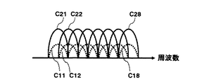
図1は、OFDM/CDMA変調方式における送信信号の一例を示す図である。なお、ここでは、周波数軸上において8個のサブキャリアを想定しており、異なる2ユーザに対する送信信号が多重化されて送信されている状態を示している。送信機における送信データ系列D1mおよびD2mは、図1において拡散符号C1n(nは整数)および拡散符号C2n(nは整数)にてそれぞれ拡散変調されている。すなわち、各サブキャリア毎に、拡散符号C11,C12,…,C18、および拡散符号C21,C22,…,C28にて拡散変調され、さらに多重化された信号が送信される。
【0008】
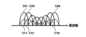
このようにサブキャリア単位で拡散変調、および多重化された信号が、遅延波が存在する周波数選択性フェージング伝送路を通った場合、各拡散チップに対応するサブキャリア信号は、たとえば、図2に示すように、各サブキャリアの振幅および位相がそれぞれ異なった状態で受信される。すなわち、周波数選択性フェージングの影響をうけた拡散チップのS/N比が低下することになり、それに伴って振幅および位相が変化する。
【0009】
上記特開2000−332724公報記載のMC−CDMA拡散チップ割り当て方法に従うOFDM/CDMA変調方式(以下「前記公報記載のマルチキャリア変調方式」と呼ぶ)では、周波数選択性フェージングが存在する伝送路において、OFDM/CDMA変調方式を採用した場合に、チップ数を多くとることを可能とし、さらにその結果として、拡散利得を向上させることができ、CDMA多重化においても多重数を増加させることができるようなマルチキャリア伝送システムを得ること、およびその変調方法を得ることを目的とし、OFDM/CDMA変調方式を採用して送信データ系列の拡散信号を周波数軸上および時間軸上に2次元的に配置し、さらに、前記2次元的に配置された一つの送信データ系列の拡散信号群を規則的に配置する拡散信号並べ替え手段(後述する実施の形態の送信機、S/P変換部314に相当)を備え、送信機側が、前記拡散信号並べ替え手段にて生成された送信信号を時間軸単位で送信し、受信機側が、受け取った受信信号を復調することにより前記送信データ系列を得るマルチキャリア伝送システムを示している。
【0010】
この方式によれば、拡散後の信号を、拡散信号並べ替え手段にて、たとえば、周波数軸上に2チップ周期分を配置し、さらに時間軸上に4チップ分を配置し、合計8チップの拡散信号群を生成する。これにより、従来のように、単純に8チップの拡散信号を周波数軸上に配置した場合と比較して、周波数選択性フェージングの影響を4分の1に抑圧することが可能となる。また、S/N比が改善されることから、拡散チップ数を従来より増加させることができるようになり、拡散利得を大きく取ることが可能となる。さらに、同時に、CDMA多重化における多重数も、従来より増加させることができる。
【0011】
また、同公報には、伝送路状態に応じてOFDM/CDMA信号を選択的に送信し、さらに前記拡散信号並べ替え手段において、前記2次元的に配置した拡散信号の周波数軸上および時間軸上における拡散チップの配置比率を伝送路状態に応じて可変とする、マルチキャリア伝送システムまたは方法が記載されており、これによれば、周波数選択性フェージング伝送路の影響を受ける伝送路や、時間変動の大きい伝送路等に容易に適応できる、としている。
【0012】
図3は、前記公報記載のマルチキャリア変調方式を採用するマルチキャリア伝送システムの構成図である。なお、図3(a)は、送信機側の構成を示すものであり、(b)は、受信機側の構成を示すものであり、本システムを構成する装置は、送信機および受信機の少なくとも一方の機能を備える。
【0013】
図3(a)において、301は第1のデータ拡散部であり、302は第2のデータ拡散部であり、303は合成部であり、304はシリアル/パラレル(S/P)変換部であり、305はIFFT(Inverse Fast Fourier transform)部であり、306はガードインターバル(GI)付加部であり、307はディジタル/アナログ(D/A)変換部である。また、図3(b)において、311はアナログ/ディジタル(A/D)変換部であり、312はガードインターバル(GI)除去部であり、313はFFT(Fast Fourier Transform)部であり、314はパラレル/シリアル(P/S)変換部であり、315はデータ逆拡散部である。
【0014】
以下、上記送信機および受信機の動作について説明する。送信機において、図中の送信データ系列D1mは、第1のデータ拡散部301にて既知の拡散符号C1nにより拡散され、一方、他ユーザーへの送信データ系列D2mは、第2のデータ拡散部302にて既知の拡散符号C2nにより拡散される。その後、両出力は、合成部303において合成される。なお、本実施の形態において、拡散符号C1nとC2nとは直交しているものとする。
【0015】
合成部303の出力信号は、シリアル/パラレル変換部304にてシリアル信号からパラレル信号に変換され、変換後のパラレル信号は、IFFT(逆高速フーリエ変換)305による逆高速フーリエ変換処理で時間軸波形に変換される。そして、時間軸波形変換後の信号には、GI付加部306にてガードインターバルが付加され、OFDM信号となる。最後に、ディジタルのOFDM信号がD/A変換器7にてアナログ信号に変換され、受信機に対して送信される。以後、この送信信号のことを、OFDM/CDMA信号と呼ぶ。なお、ガードインターバル信号とは、建造物等に反射して生じる遅延信号の影響を吸収するために設定されるもので、OFDM変調信号においては、通常、使用されるものである。
【0016】
つぎに、上記OFDM/CDMA信号を受け取った受信機では、その受信信号をA/D変換器311にてディジタル信号に変換し、GI除去部312にてガードインターバルを除去する。そして、ガードインターバル除去後の信号は、FFT313にて高速フーリエ変換処理され、時間軸波形を周波数軸波形に変換する。その後、FFT313からの出力信号は、P/S変換部314にてシリアル信号に変換され、データ逆拡散部315に送信される。
【0017】
たとえば、着目するユーザーの拡散符号が上記C1nである場合、シリアル変換後の信号は、データ逆拡散部315にて、ユーザー固有の拡散符号C1nと乗算され、送信データ系列D1mとして再生されることになる。これに対して、同時に受信される拡散符号C2mで拡散されたデータ系列D2mは、拡散符号C1nとC2nとの直交性により除去されることになる。また、建造物等に起因する遅延波の影響は、OFDM信号のガードインターバルにて除去されている。
【0018】
上述の、前記公報記載のマルチキャリア変調方式によるマルチキャリア伝送システムの動作において、通常、OFDM/CDMA信号は、たとえば、図1および図2に示すような形式で、周波数軸上の各サブキャリアに一つのデータを振り分けて送信する。しかしながら、このような方法では、周波数選択性フェージングの存在する伝送路をとおる場合、その影響を受けた周波数のサブキャリアにおけるデータに誤りが発生し、以後、このサブキャリアにおける同一データ部分に常に誤りが発生することになる。
【0019】
そこで、前記公報記載のマルチキャリア変調方式においては、OFDM/CDMA信号の生成処理におけるデータの配置を変えることで、周波数選択性フェージングの影響を少なくしている。
【0020】
上述した前記公報記載のマルチキャリア変調方式の実施の形態1では、第1のデータ拡散部301および第2のデータ拡散部302にて拡散後の信号を、S/P変換部304にて、たとえば、周波数軸上に2チップ周期分を配置し、さらに時間軸上に4チップ分を配置し、合計8チップの拡散信号に適用した場合を示している。このような処理を行うことにより、従来のように、単純に8チップの拡散信号を周波数軸上に配置した場合と比較して、周波数選択性フェージングの影響を4分の1に抑圧することが可能となる。すなわち、サブキャリア数を8個とした場合、従来、8チップ(1データ系列)のうちの1チップが常に周波数選択性フェージングの影響を受ける場合でも、本実施の形態では、4データ系列に一つの割合でしか周波数選択性フェージングの影響を受けないことになる。
【0021】
これにより、S/N(Signal to Noise Ratio )比が改善されることから、拡散チップ数を従来より増加させることができるようになり、拡散利得を大きく取ることが可能となる。また、同時に、CDMA多重化における多重数も、増加させることができる。
【0022】
また、前記公報記載のマルチキャリア変調方式によるマルチキャリア伝送システムの他の実施の形態として、前記S/P変換部304にて、たとえば、周波数軸上に2チップ周期分を配置し、さらに時間軸上に4チップ分を配置した後、各周波数群の配置を時間軸上でシフトする方法(実施の形態2)、前記S/P変換部304にて、たとえば、周波数軸上に2チップ周期分を配置し、さらに時間軸上に4チップ分を配置した後、各周波数群の配置を周波数軸上でシフトする方法(実施の形態3)、前記S/P変換部304にて、2チップ毎に一つのグループとして4グループに分解し、その各グループをOFDM信号内でインターリーブを行う方法(実施の形態4)、および前記S/P変換部304が、前記実施の形態1〜4におけるS/P変換部の機能をすべて備え、その中から、伝送路状態に応じたOFDM/CDMA信号を選択的に送信するようにした方法(実施の形態5)、を開示している。さらに、伝送路状態に応じて、周波数軸上および時間軸上に割り当てる拡散チップ比率を可変とすれば、周波数選択性フェージング伝送路の影響を受ける伝送路や、時間変動の大きい伝送路等に容易に適応させることができる、と主張している。
【0023】
上記のように、前記公報には、「伝送路状態に応じて、周波数軸上および時間軸上に割り当てる拡散チップの比率を可変とすることにより、周波数選択性フェージング伝送路の影響を受ける伝送路や、時間変動の大きい伝送路等に、容易に適応する。」と記載してあるが、上記2次元的に配置した拡散信号の、周波数軸上および時間軸上における配置比率を、伝送路の状態に応じて最適に決める具体的方法については開示されていない。
【0024】
【発明が解決しようとする課題】
本発明は、前記公報記載のマルチキャリア変調方式によるマルチキャリア伝送システムによって実施することが不可能な、前記2次元的に配置した拡散信号の周波数軸上および時間軸上における配置比率を、伝送路状態にどのように応じて最適に決定するかについての、具体的な方法を提供することを目的とする。
【0025】
【課題を解決するための手段】
上記目的を達成するため、本発明のMC−CDMA拡散チップ割り当て方法は、移動局は、周波数軸上の振幅変動(遅延スプレッド)を測定する部位、及び測定された振幅変動を基地局に通知する部位を備え、基地局は、周波数軸上の振幅変動及びユーザ多重数に対する最適な周波数軸方向拡散数を記憶するテーブルを保持すると共に、セル内の各移動局から通知される周波数軸上の振幅変動の分布に基づき最適な周波数軸上の振幅変動を決定する部位を備え、上記決定された周波数軸上の振幅変動とユーザ多重数に応じて、上記テーブルから 最適な周波数軸方向拡散数を選択し、次いで各移動局に割り当てられる拡散コード長から各移動局に対する時間軸方向拡散数を求めて、基地局はそれに従い拡散チップを周波数軸上と時間軸上に同時に割り当てて2次元配置を行い、拡散コード長とあわせて周波数軸方向拡散数を移動局に通知することを特徴とする。
【0026】
あるいは、本発明のMC−CDMA拡散チップ割り当て方法は、移動局は、時間軸上の振幅変動(ドップラー周波数)を測定する部位、及び測定された振幅変動を基地局に通知する部位を備え、基地局は、時間軸上の振幅変動及びユーザ多重数に対する最適な時間軸方向拡散数を記憶するテーブルを保持すると共に、セル内の各移動局から通知される時間軸上の振幅変動の分布に基づき最適な時間軸上の振幅変動を決定する部位を備え、上記決定された時間軸上の振幅変動とユーザ多重数に応じて、上記テーブルから最適な時間軸方向拡散数を選択し、次いで各移動局に割り当てられる拡散コード長から各移動局に対する周波数軸方向拡散数を求めて、基地局はそれに従い拡散チップを周波数軸上と時間軸上に同時に割り当てて2次元配置を行い、拡散コード長とあわせて時間軸方向拡散数を移動局に通知することを特徴とする。
【0027】
あるいは、本発明のMC−CDMA拡散チップ割り当て方法は、移動局は、周波数軸上の振幅変動(遅延スプレッド)を測定する部位、時間軸上の振幅変動(ドップラー周波数)を測定する部位、及び測定された2つの振幅変動を基地局に通知する部位を備え、基地局は、周波数軸上の振幅変動及び時間軸上の振幅変動及びユーザ多重数に対する最適な周波数軸方向拡散数及び時間軸方向拡散数を記憶するテーブルを保持すると共に、セル内の各移動局から通知される周波数軸上の振幅変動と時間軸上の振幅変動の分布に基づき最適な周波数軸上の振幅変動と時間軸上の振幅変動を決定する部位を備え、上記決定された周波数軸上の振幅変動及び時間軸上の振幅変動とユーザ多重数に応じて、上記テーブルから最適な周波数軸方向拡散数と時間軸方向拡散数を選択し、基地局はそれに従い拡散チップを周波数軸上と時間軸上に同時に割り当てて2次元配置を行い、周波数軸方向拡散数と時間軸方向拡散数を移動局に通知することを特徴とする。
【0028】
さらに、上記各構成において、前記周波数軸上の振幅変動及び/または時間軸上の振幅変動の分布から算出した該振幅変動に対する移動局存在確率の累積確率分布における所定の累積存在確率の振幅変動許容値を求め、該振幅変動値に対応する最適拡散数を求めることを特徴とする。
【0029】
またさらに、前記テーブルが、コード多重数をパラメータとし、前記振幅変動許容値に対応した所定の符号誤り率が得られる最大許容拡散数を記録するものであって、前記振幅変動許容値に対応する最適拡散数を上記テーブルから求めることを特徴とする。
【0030】
【発明の実施の形態】
以下、図面を参照して、本発明の実施の形態を説明する。
周波数軸方向拡散を行うMC−CDMA方式において、遅延スプレッドが大きい伝搬路環境では、周波数選択性フェージングの影響により周波数軸上に拡散されたチップ電力の変動が大きくなる。また、拡散長が大きければチップ間の振幅相関はさらに小さくなる。拡散コード内のチップ間の振幅相関が小さくなれば、周波数ダイバーシチ効果が大きく得られる。しかし、コード多重により実現される多ユーザ通信時に・チップ間の振幅相関が小さくなれば、拡散コード間の直交性が崩れ、符号間干渉が発生することにより伝送品質は劣化する。すなわち、周波数軸方向拡散を行うMC−CDMA方式においてコード多重を行った場合では、周波数ダイバーシチ効果と符号間干渉の低減とはトレードオフの関係ある。一方、周波数選択性フエージグの影響によりチップ間の振幅変動が生じないようにするために、時間軸方向にコード拡散を行うMC−CDMA方式も提案されている。コード拡散を時間軸方向とすることで周波数選択性フエージングによりチップ間の振幅変動は生じない。しかし、移動局の移動速度の増加に伴ってドップラー周波数が増加すれば、チップ間の電力変動幅は大きくなり、振幅相関が小さくなる。また、拡散方向が時間方向のため、拡散長が大きくなれば伝送時間が増大してしまう。
【0031】
本発明においては、MC−CDMA方式において多ユーザ通信を行う際に通信品質の向上を図るため、以下の手段を用いる。
コード拡散されたシンボルのサブキャリア割り当てを、周波数軸方向拡散数PGfおよび時間軸方向拡散数PGtのPGf×PGt=PGとなる2次元配置とする。
【0032】
まず、伝搬路にて生じる周波数選択性フエージングによって変化する振幅変動を移動局にて測定する。測定された振幅変動値は基地局に通知される。基地局は各移動局から通知される振幅変動値の分布を保持し、その分布からセル内の移動局に適用するための最適な振幅変動値を決定する。テーブル情報を参照して、決められた振幅変動値から周波数軸方向の最大拡散可能数PGfmaxが決まるが、ユーザ多重数Kに応じて異なるようにする。Kが小さいときはコード干渉の影響は小さいためPGfmaxは大きく、Kが大きいときはPGfmaxは小さい。振幅変動値が小さい伝搬路環境ではPGfmaxは大きく、振幅変動値が大きい場合PGfmaxは小さく設定することになる。このとき拡散長PGがPG>PGfmaxであれば、周波数軸方向拡散数をPGf =PGfmax、時間軸方向拡散数をPGt =PG/PGfmax とする。
【0033】
また、端末移動に伴い発生するドップラー周波数の増加による時間軸上の振幅変動を移動局にて測定する。測定された振幅変動値は基地局に通知される。基地局は各移動局から通知される振幅変動値の分布を保持し、その分布からセル内の移動局に適用するための最適な振幅変動値を決定する。テーブル情報を参照して、決められた振幅変動値から時間軸方向の最大拡散可能数PGfmaxが決まるが、ユーザ多重数Kに応じて異なるようにする。Kが小さいときはコード干渉の影響は小さいためPGtmaxは大きく、Kが大きいときはPGtmaxは小さい。振幅変動値が小さい伝搬路環境ではPGtmaxは大きく、振幅変動値が大きい場合PGtmaxは小さく設定することになる。このとき拡散長PGがPG>PGtmaxであれば、時間軸方向拡散数をPGt =PGtmax、周波数軸方向拡散数をPGf =PG/PGtmaxとする。
【0034】
図4は本発明のMC−CDMA拡散チップ割り当て方法の実施例である。図4において、401は送信データソース、402はシリアル・パラレル変換部、403はスペクトル拡散部、404はマッパー、405は逆フーリエ変換(IFFT)部、406はガードインターバル(GI)付加部、407は振幅変動分布収集部、408は制御部、409は最適PGf (PGt )値テーブル部、410はGI除去部、411はFFT部、412はデマッパー、413はスペクトラム逆拡散部、414はパラレル・シリアル(P/S)変換部、415は基地局制御部から移動局のデマッパーに対して通知される、スペクトル拡散されたシンボルのサブキャリア割り当て情報、416は移動局、417は移動局内のMC−CDMA受信部、418はGI除去部、419はフーリエ変換(FFT)部、4に0はデマッパー、421はサブキャリア振幅変動測定部、422はMC−CDMA送信部、423は移動局から基地局の振幅変動分布収集部407に対して通知される、受信信号の振幅変動測定値情報である。
【0035】
基地局からセル内の移動局に対して発信される送信データソース401は、並列データ処理を行うためS/P変換部402によって並列データ系列に変換された後、拡散部403にてコード拡散される。このコード拡散されたデータ系列に対して、マッパー404がサブキャリアの割り当てを、拡散数PGが周波数軸方向拡散数PGf および時間軸方向拡散数PGt の積で表わされる(PG=PGf ×PG t )ような2次元配置として割り当てる。2次元拡散された信号はIFFT部405にて時間軸信号に変換され、GI付加部406にてガードインターバルが付加された後、A/Dコンバータ(図には示していない)でアナログ信号に変換されて、セル内移動局に向けて送信される。
【0036】
基地局の受信部においては、受信した移動局からの信号のガードインターバルをGI除去部410で除去し、FFT部411で周波数軸信号に変換後、デマッパー412により、マッパー404で決められた周波数軸方向および時間軸方向の拡散配置にもとづいて拡散チップの復元を行ない、逆拡散部413にて並列データ系列を再現する。さらにこれをP/S変換部414によって直列データに直して出力する。移動局のMC−CDMA受信部417はGI除去部418、FFT部419およびデマッパ420で構成され、その各部の動作は前記基地局の受信部のGI除去部410、FFT部411、およびデマッパー412のそれぞれの動作と基本的に同じである。以上述べたMC−CDMA基地局および移動局の構成要素とその動作は、周波数軸方向および時間軸方向の拡散数をあらかじめ一定値に定める従来の2次元拡散配置MC−CDMA方式の構成および動作と同一であり、既知のものである。
【0037】
本発明のMC−CDMA拡散チップ割り当て方法によるMC−CDMA基地局および移動局の構成においては、図4に示すように前記従来の構成要素に加えて、移動局416は周波数軸上の振幅変動(遅延スプレッド)(および/または時間軸上の振幅変動(ドップラー周波数))を測定する部位(すなわちサブキャリア振幅変動測定部421)を備える。なお、測定された周波数軸上(および/または時間軸上)の振幅変動を基地局に通知する部位としては、従来の構成におけるMC−CDMA送信部422をそのまま使用し、これによって、測定された振幅変動情報423は基地局のサブキャリア振幅分布収集部407に送られる。
【0038】
さらに本発明のMC−CDMA基地局400は、周波数軸上の振幅変動及び時間軸上の振幅変動およびユーザ多重数に対する最適な周波数軸方向拡散数及び時間軸方向拡散数を記憶するテーブル(すなわち最適PGf (PGt )値テーブル部409)、およびセル内の各移動局から通知される周波数軸上(および/または時間軸上 )の振幅変動の分布に基づき、最適な周波数軸上(および/または時間軸上)の振幅変動を決定する部位(すなわち振幅変動分布収集部407および制御部408)を備える。さらに制御部408においては、決定された周波数軸上(および/または時間軸上)の最適な振幅変動値とユーザ多重数(すなわち送信データソースからあらかじめ通知されるコード多重数K)から、最適PGf (PG t )値テーブル部409を参照して最適拡散数PGf (および/またはPGt )を決定する。制御部408で決定された最適拡散数PGf (および/またはPGt )はマッパー404に通知され、マッパー404ではそれに従って2次元拡散を実行する。また制御部408で決定された最適拡散数PGf (および/またはPGt )の値(図4のスペクトル拡散されたシンボルのサブキャリア割り当て情報415)は、移動局において受信信号を復元する際に必要な情報として、移動局のデマッパー416に送られる。
【0039】
以上説明した構成および各部の動作により、移動局は、周波数軸上の振幅変動(遅延スプレッド)(および/または時間軸上の振幅変動(ドップラー周波数))を測定する部位、測定された周波数軸上(および/または時間軸上)の振幅変動を基地局に通知する部位を備え、基地局は周波数軸上(および/または時間軸上)の振幅変動、及びユーザ多重数に対する最適な周波数軸方向拡散数(および/または時間軸方向拡散数)を記憶するテーブルを保持し、セル内の各移動局から通知される周波数軸上(および/または時間軸上)の振幅変動の分布に基づき、最適な周波数軸上(および/または時間軸上)の振幅変動を決定する部位を備え、決定された周波数軸上(および/または時間軸上)の振幅変動とユーザ多重数とに応じて、最適な周波数軸方向拡散数(および/または時間軸方向拡散数)を選択し、基地局はそれに従い拡散チップを周波数軸上と時間軸上に同時に割り当てて2次元配置を行い、周波数軸方向拡散数(および/または時間軸方向拡散数)を移動局に通知することを特徴とするMC−CDMA拡散チップ割り当て方法を実現している。
【0040】
つぎに、本発明の主要構成要素であるサブキャリア振幅変動測定部(図4の421)、振幅変動分布収集部(同407)、制御部(同408)及び最適PGf (PG t )値テーブル部(同409)の構成について、図面を参照しつつ詳細に説明する。
【0041】
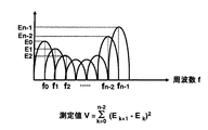
図5は、本発明のMC−CDMA拡散チップ割り当て方法によるMC−CDMA方式の、移動局416における周波数軸上の振幅変動(遅延スプレッド)(および/または時間軸上の振幅変動(ドップラー周波数))を測定する部位(すなわちサブキャリア振幅変動測定部421)において、測定すべき周波数軸上の振幅変動(遅延スプレッド)(および/または時間軸上の振幅変動(ドップラー周波数))の例を示す。ここで例えば周波数軸上の振幅変動を測定する場合は、図5の502で示した周波数領域での受信電力Eを各サブキャリア毎に測定し(実際は各サブキャリア毎のパイロット信号の受信電力を測定するだけでよく、その場合位相の補正は必要ない)、隣接サブキャリア間の受信電力差分の二乗の積算値を振幅変動の測定値Vとする。図6はその例を示したもので、サブキャリア周波数f0 に対する受信電力測定値がE0 、サブキャリア周波数f1 に対する受信電力測定値がE1 ,・・・等の時、受信電力の測定値Vは図6中の数式で計算される。
【0042】
同様に、時間軸上の振幅変動を測定する場合は、図5の503で示す時間軸上の電力を測定する。この場合の測定値の例を図7に示す。時刻t0 ,t1 ,・・・・における受信電力測定値をE0 ,E1 ,・・・・とするとき、受信電力の測定値Vとしては、図7中の数式で計算される。
【0043】
基地局400における振幅変動分布収集部(同407)は、セル内の各移動局から送られてくる受信電力の振幅変動測定値(V)を入力して、それら個々の値を出力した移動局の数を記録する。この測定例が図8(a)に示される。
【0044】
ここで、振幅変動測定値Vに対する移動局数の分布が図8(a)のようになるとき、振幅変動測定値Vの移動局存在確率の累積確率分布は、同図(b)のようになる。これをグラフで表わしたものが同図(c)である。
【0045】
このときセル内の振幅変動の許容値をV0 で表わすことにして、V0 をたとえば累積確率80%に対するVとすれば、図8(c)に示される如く、セル内振幅変動の許容値V0 の値はV0 =αとして求められる。
【0046】
すなわち、振幅変動をV0 =αに設定すれば、そのセル内の移動局の80%は振幅変動がV0 =α以下となる。このV0 =αに対応する最適な拡散数を求めるのがこの発明である。以下、その具体的方法が詳述される。
【0047】
つぎに、制御部(図4の408)の動作を説明する。制御部408においては、振幅変動分布収集部(同407)によって決定された周波数軸上(または/および時間軸上)の最適な振幅変動値(上記の説明におけるV0 )とユーザ多重数(すなわち送信データソースからあらかじめ通知されるコード多重数K)から、最適PGf (PGt )値テーブル部409を参照して最適拡散数PGf (または/およびPGt )を決定する。制御部408で決定された最適拡散数PGf (または/およびPGt )はマッパー404に通知され、マッパー404ではそれに従って2次元拡散を実行する。
【0048】
また、制御部408で決定された最適拡散数PGf (および/またはPGt )の値(図4のスペクトル拡散されたシンボルのサブキャリア割り当て情報415)は、移動局において受信信号を復元する際に必要な情報として、移動局のデマッパー416に送られる。
【0049】
なお、スペクトル拡散されたシンボルのサブキャリア割り当て情報415は、図4では制御部408から直接移動局のデマッパー420に送られるように破線で示してあるが、これは情報の流れを示すもので、実際の信号としては主信号データと共に基地局から送出される制御データの一部として、MC−CDMA信号の中に含めて移動局に伝達される。
【0050】
つぎに、制御部(図4の408)が、振幅変動分布収集部(同407)によって決定された周波数軸上(および/または時間軸上)の最適な振幅変動値V0 と、送信データソースからあらかじめ通知されるコード多重数Kとから、最適拡散数PGf (および/またはPGt )を決定するのに必要な、最適PGf (PGt )値テーブル部(図4の409)のテーブル数値の作製方法を説明する。図9は、コード多重数Kと振幅変動値Vとが与えられたとき、所要の符号誤り率(BERrq以下)が得られるためのPGの値の範囲を示す図である。周波数軸上の最適拡散数PGf を決定する場合と、時間軸上の最適拡散数PGt を決定する場合の手法は全く同一なので、ここでは簡単のため最適拡散数の表記として、共通のPGを用いている。
【0051】
図9(a)はコード多重数Kとして比較的大きな値が与えられたとき、振幅変動値Vに対して所要の符号誤り率(BERrq以下)が得られるためのPGの値の範囲を示す。図中の曲線901は、比較的大きなPGの値を選択した時の振幅変動値Vと符号誤り率BERの関係の例を示すもので、符号誤り率を所要のBERrq以下に保つための振幅変動値Vの範囲としては、太い線分904に相当する横軸座標範囲になければならない。同様に曲線902は、中位の大きさのPGの値を選択した時の振幅変動値Vと符号誤り率BERの関係の例を示すもので、符号誤り率を所要のBERrq以下に保つための振幅変動値Vの範囲としては、太い線分905およびその左側に相当する横軸座標範囲になければならない。同様に曲線903は、比較的小さなPGの値を選択した時の振幅変動値Vと符号誤り率BERの関係の例を示すもので、符号誤り率を所要のBERrq以下に保つための振幅変動値Vの範囲としては太い線分906およびその左側に相当する横軸座標範囲になければならない。逆に、振幅変動値Vが一定値(たとえば前記のように振幅変動分布収集部(同407)で算出されたセル内の振幅変動代表値V0 )として与えられる時、その値(V0 )が図9(b)の横軸上の何処にあるかによって、PGの取り得る最大値(すなわち最適値が定まる。たとえば同図に示したV0 の位置の場合、PGとしては線分905より下方の値をとり得るが、その中で最大のもの、すなわち線分905に相当する中位の大きさのPGが、最適拡散数となる。
【0052】
図9(b)はコード多重数Kとして比較的小さな値が与えられたとき、振幅変動値Vに対して所要の符号誤り率(BERrq以下)が得られるためのPGの値の範囲を示す。図9(a)と対比して分かるように、コード多重数Kが大の時に比べ、コード多重数が小の場合は、振幅変動値の符号誤り率(BERrq)に与える影響は小さい。図9(a)と同様に、図中の曲線907は、比較的大きなPGの値を選択した時の振幅変動値Vと符号誤り率BERの関係の例を示すもので、符号誤り率を所要のBERrq以下に保つための振幅変動値Vの範囲としては、太い線分910に相当する横軸座標範囲になければならない。同様に曲線908は、中位の大きさのPGの値を選択した時の振幅変動値Vと符号誤り率BERの関係の例を示すもので、符号誤り率を所要のBERrq以下に保つための振幅変動値Vの範囲としては、太い線分911およびその左側に相当する横軸座標範囲になければならない。同様に曲線909は、比較的小さなPGの値を選択した時の振幅変動値Vと符号誤り率BERの関係の例を示すもので、符号誤り率を所要のBERrq以下に保つための振幅変動値Vの範囲としては太い線分911およびその左側に相当する横軸座標範囲になければならない。逆に、振幅変動値Vが一定値(たとえば前記のように振幅変動分布収集部(同407)で算出されたセル内の振幅変動許容値(V0 )として与えられる時、その値(V0 )が図9(b)の横軸上の何処にあるかによって、PGの取り得る最大値(すなわち最適値が定まる。たとえば同図に示したV0 の位置の場合、PGとしては線分910より下方の値をとり得るが、その中で最大のもの、すなわち線分910に相当する比較的大きな値のPGが、最適拡散数となる。
【0053】
図10は、図9に示した関係から定まるPGの値の範囲を、種々のコード多重数Kと振幅変動値(の代表値、たとえば図8で説明したセル内の振幅変動の代表値V0 )とについて示したものである。同図の各曲線の下側(ハッチを施した部分)に記されているPG値(PG1 ,PG2 ,・・・PGm-2 ,PGm-1 ,PGm 等、ここでPG1 <PG2 <・・・<PGm-2 <PGm-1 <PGm )が、許容される最大のPG、すなわち最適PG値(周波数軸上の場合PGfmax、時間軸上の場合PGtmax)となる。たとえば与えられたKの値をk0 とし、また振幅変動の代表値V0 としてたとえば図8で説明したように実測値の80%累積確率値αを採用すれば、両者の交点の座標位置に相当するPG値、すなわちこの例の場合PGm-2 が最適PG値となる。
【0054】
最適PGf (PGt )値テーブル部(図4の409)には、種々のV0 およびKの値に対するPGの値を上記説明した方法に従ってあらかじめ作表し、記入しておく。制御部(図4の408)は、振幅変動分布収集部407によって実際の伝播路の状態に応じて求められたK、V0 の値を、テーブル部409に格納されている表にあてはめ、最適PGf (PGt )の値を取り出す。
【0055】
【発明の効果】
以上述べたように、従来のMC−CDMA方式においては、コード多重した多ユーザの通信時に、コード拡散方向が一律であることを要因として通信品質の劣化が引き起こされる可能性があった。本発明により、伝搬路環境や移動局移動速度に応じて適応的にコード拡散方向と最大拡散可能数を設定し、周波数軸方向と時間軸方向の2次元配置を、テーブルを参照することにより簡便に行うことができる。これにより、拡散コード内のチップ電力相関を所要値以上に保つことで多ユーザ通信時の符号間干渉を低減し通信品質の向上を図ることが可能になる。また、1コード伝送時間を一定にすることも可能であり、通信品質を柔軟に設計することが可能となる。
【図面の簡単な説明】
【図1】OFDM/CDMA変調方式における送信信号の一例を示す図である。
【図2】各サブキャリヤの振幅および位相がそれぞれ異なった状態で受信された時の、受信信号の一例を示す図である。
【図3】特開2000−332724公報に記載のマルチキャリア変調方式を採用するマルチキャリア伝送システムの構成図である。
【図4】本発明のMC−CDMA拡散チップ割り当て方法に用いるシステムの実施例を示す図である。
【図5】本発明のMC−CDMA拡散チップ割り当て方法によるMC−CDMA方式の、測定すべき周波数軸上の振幅変動(遅延スプレッド)(または/および時間軸上の振幅変動(ドップラー周波数))の例を示す図である。
【図6】周波数軸上の振幅変動の測定値の例を示す図である。
【図7】時間軸上の振幅変動の測定値の例を示す図である。
【図8】振幅変動分布収集部の動作の一例を示す図である。
【図9】コード多重数Kと振幅変動値Vとが与えられたとき、所要の符号誤り率(BERrq以下)が得られるためのPGの値の範囲を示す図である。
【図10】図9に示した関係から定まるPGの値の範囲を、種々のコード多重数Kと振幅変動値とについて示したものである。
【符号の説明】
301 第1のデータ拡散部
302 第2のデータ拡散部
303 合成部
304 シリアル/パラレル(S/P)変換部
305 IFFT(Inverse Fast Fourier transform)部
306 ガードインターバル(GI)付加部
307 ディジタル/アナログ(D/A)変換部
311 アナログ/ディジタル(A/D)変換部
312 ガードインターバル(GI)除去部
313 FFT(Fast Fourier Transform)部
314 パラレル/シリアル(P/S)変換部
315 データ逆拡散部
401 送信データソース
402 シリアル・パラレル変換部
403 スペクトル拡散部
404 マッパー
405 逆フーリエ変換(IFFT)部
406 ガードインターバル(GI)付加部
407 振幅変動分布収集部
408 制御部
409 最適PGf (PGt )値テーブル部
410 GI除去部
411 FFT部
412 デマッパー
413 スペクトラム逆拡散部
414 パラレル・シリアル(P/S)変換部
415 スペクトル拡散されたシンボルのサブキャリア割り当て情報
416 移動局
417 MC−CDMA受信部
418 GI除去部
419 フーリエ変換(FFT)部
420 デマッパー
421 サブキャリア振幅変動測定部
422 MC−CDMA送信部
423 受信信号の振幅変動測定値情報
500 移動局が受信したMC−CDMA信号
501 移動局が受信したMC−CDMA信号の振幅変動測定用信号
502 周波数領域での受信電力
503 時間軸上の受信電力
901 大きなPG値に対する振幅変動値Vと符号誤り率BERの関係を示す曲線
902 中位のPG値に対する振幅変動値Vと符号誤り率BERの関係を示す曲線
903 小さなPG値に対する振幅変動値Vと符号誤り率BERの関係を示す曲線
904 所要のBERrq以下に保つための振幅変動値Vの範囲を示す太い線分
905 所要のBERrq以下に保つための振幅変動値Vの範囲を示す太い線分
906 所要のBERrq以下に保つための振幅変動値Vの範囲を示す太い線分
907 大きなPG値に対する振幅変動値Vと符号誤り率BERの関係を示す曲線
908 中位のPG値に対する振幅変動値Vと符号誤り率BERの関係を示す曲線
909 小さなPG値に対する振幅変動値Vと符号誤り率BERの関係を示す曲線
910 所要のBERrq以下に保つための振幅変動値Vの範囲を示す太い線分
911 所要のBERrq以下に保つための振幅変動値Vの範囲を示す太い線分
912 所要のBERrq以下に保つための振幅変動値Vの範囲を示す太い線分[0001]
BACKGROUND OF THE INVENTION
The present invention relates to a multi-carrier CDMA (hereinafter referred to as MC-CDMA) system, which is one of radio transmission systems, and particularly, OFDM (Orthogonal Frequency Division Multiplexing) / CDMA, which is a kind of multi-carrier transmission system. The present invention relates to a spreading chip allocation method and its application in a multicarrier transmission system that employs a (Code Division Multiple Access) modulation scheme.
[0002]
[Prior art]
In recent years, digital modulation schemes and transmission schemes for transmitting images and sounds at high speed have been studied in the fields of mobile communication and digital broadcasting. In particular, the CDMA system is often used for mobile radio because frame synchronization in TDMA is unnecessary.
[0003]
Among them, it has recently been strong against frequency selective fading, a frequency diversity effect can be obtained by combining error correction coding, the frequency interval of each subcarrier can be set densely, and a guard in the symbol interval Multi-carrier transmission systems that employ an OFDM / CDMA modulation scheme, which is a kind of multi-carrier transmission scheme, have attracted attention because of the advantages that the influence of intersymbol interference can be reduced by setting the interval.
[0004]
The MC-CDMA system, which is being studied for use in broadband wireless transmission, is a multicarrier transmission system that transmits symbols spread by a spreading code using a plurality of subcarriers arranged at orthogonal frequency intervals. The code spreading direction is generally spread in the frequency axis direction. At this time, if the spreading length is PG and the number of subcarriers is N, N / PG symbols are transmitted in parallel. One of the features of the MC-CDMA system that performs code spreading in the frequency axis direction is that a frequency diversity effect can be obtained because the spreading chip is assigned to subcarriers having different center frequencies. Also, the greater the spreading length PG, the greater the frequency diversity effect the smaller the correlation between subcarriers to which spreading chips are assigned. It has also been proposed to perform code spreading in the time axis direction. In both the frequency axis direction spreading and the time axis direction spreading, the code spreading direction is fixed in advance on both sides of transmission and reception, and a despreading process is performed on the receiver side according to the code spreading direction to obtain a transmission symbol.
[0005]
When performing multi-user communication in the MC-CDMA system, the code spreading direction, the propagation path environment, and the moving speed of the mobile station are closely related from the viewpoint of ensuring communication quality. In other words, the code spreading direction is fixedly determined.
[0006]
Japanese Patent Laid-Open No. 2000-332724 is known as an improved example of such OFDM / CDMA. Hereinafter, this improved example will be described first.
The OFDM / CDMA modulation scheme is a technique for performing OFDM modulation on a signal after spread spectrum, and the frequency interval is set so that the carriers are orthogonal to each other within a symbol interval. Information is transmitted by changing the amplitude and phase of each carrier.
[0007]
FIG. 1 is a diagram illustrating an example of a transmission signal in the OFDM / CDMA modulation scheme. Here, eight subcarriers are assumed on the frequency axis, and a state is shown in which transmission signals for two different users are multiplexed and transmitted. Transmission data series D1m and D2m in the transmitter are spread and modulated by spreading code C1n (n is an integer) and spreading code C2n (n is an integer) in FIG. That is, for each subcarrier, a spread signal modulated by spread codes C11, C12,..., C18 and spread codes C21, C22,.
[0008]
When a signal modulated and multiplexed in units of subcarriers as described above passes through a frequency selective fading transmission line in which a delay wave exists, the subcarrier signal corresponding to each spreading chip is, for example, shown in FIG. As shown, the subcarriers are received with different amplitudes and phases. That is, the S / N ratio of the diffusion chip affected by frequency selective fading decreases, and the amplitude and phase change accordingly.
[0009]
In the OFDM / CDMA modulation scheme (hereinafter referred to as “multi-carrier modulation scheme described in the publication”) according to the MC-CDMA spreading chip allocation method described in JP 2000-332724 A, in a transmission path in which frequency selective fading exists, When the OFDM / CDMA modulation scheme is adopted, it is possible to increase the number of chips, and as a result, the spreading gain can be improved and the number of multiplexing can be increased even in CDMA multiplexing. In order to obtain a multicarrier transmission system and to obtain a modulation method thereof, an OFDM / CDMA modulation scheme is adopted, and a spread signal of a transmission data sequence is two-dimensionally arranged on a frequency axis and a time axis, Further, the spread signal group of one transmission data sequence arranged two-dimensionally is regularly arranged. Spreading signal rearranging means to be arranged (a transmitter in an embodiment described later, corresponding to the S / P converter 314) is provided, and the transmitter side transmits the transmission signal generated by the spread signal rearranging means in units of
[0010]
According to this method, the spread signal is rearranged by the spread signal rearranging means, for example, 2 chip periods are arranged on the frequency axis, and 4 chips are arranged on the time axis, for a total of 8 chips. A spread signal group is generated. As a result, it is possible to suppress the influence of frequency selective fading to a quarter as compared with the conventional case where an 8-chip spread signal is simply arranged on the frequency axis. Further, since the S / N ratio is improved, the number of diffusion chips can be increased as compared with the conventional case, and a large diffusion gain can be obtained. Furthermore, at the same time, the number of multiplexing in CDMA multiplexing can be increased as compared with the conventional technique.
[0011]
The publication also discloses that an OFDM / CDMA signal is selectively transmitted according to a transmission path state, and further, on the frequency axis and the time axis of the two-dimensionally arranged spread signal in the spread signal rearranging means. A multi-carrier transmission system or method is described in which the arrangement ratio of spreading chips in the transmitter is variable according to the transmission line state. According to this, a transmission line affected by a frequency-selective fading transmission line or a time variation is described. It can be easily adapted to large transmission lines.
[0012]
FIG. 3 is a configuration diagram of a multicarrier transmission system that employs the multicarrier modulation system described in the publication. 3A shows the configuration on the transmitter side, FIG. 3B shows the configuration on the receiver side, and the devices constituting this system are the transmitter and receiver configurations. At least one of the functions is provided.
[0013]
In FIG. 3A, 301 is a first data diffusion unit, 302 is a second data diffusion unit, 303 is a synthesis unit, and 304 is a serial / parallel (S / P) conversion unit. , 305 is an IFFT (Inverse Fast Fourier transform) unit, 306 is a guard interval (GI) adding unit, and 307 is a digital / analog (D / A) converting unit. 3B,
[0014]
Hereinafter, operations of the transmitter and the receiver will be described. In the transmitter, a transmission data sequence D1m in the figure is spread by a known spreading code C1n in the first
[0015]
The output signal of the
[0016]
Next, in the receiver that receives the OFDM / CDMA signal, the A /
[0017]
For example, when the spreading code of the user of interest is C1n, the signal after serial conversion is multiplied by the user-specific spreading code C1n by the
[0018]
In the operation of the multi-carrier transmission system based on the multi-carrier modulation method described in the above publication, the OFDM / CDMA signal is normally transmitted to each subcarrier on the frequency axis in the form shown in FIGS. 1 and 2, for example. Sort and send one piece of data. However, in such a method, when a transmission path in which frequency selective fading exists is present, an error occurs in data on the subcarrier of the affected frequency, and thereafter, the same data portion in this subcarrier is always erroneous. Will occur.
[0019]
Therefore, in the multicarrier modulation system described in the above publication, the influence of frequency selective fading is reduced by changing the data arrangement in the OFDM / CDMA signal generation processing.
[0020]
In the first embodiment of the multi-carrier modulation method described in the above publication, the signal after spreading by the first
[0021]
As a result, the S / N (Signal to Noise Ratio) ratio is improved, so that the number of diffusion chips can be increased as compared with the prior art, and the diffusion gain can be increased. At the same time, the number of multiplexing in CDMA multiplexing can be increased.
[0022]
Further, as another embodiment of the multicarrier transmission system based on the multicarrier modulation system described in the above publication, the S /
[0023]
As described above, the above publication discloses that a transmission line that is affected by a frequency selective fading transmission line by changing a ratio of spreading chips to be allocated on the frequency axis and the time axis according to the transmission line state. It can be easily adapted to transmission lines with large time fluctuations, etc. ”, but the arrangement ratios of the spread signals arranged two-dimensionally on the frequency axis and the time axis are expressed as follows. A specific method for optimally determining according to the state is not disclosed.
[0024]
[Problems to be solved by the invention]
According to the present invention, an arrangement ratio on the frequency axis and the time axis of the spread signals arranged two-dimensionally, which cannot be implemented by the multicarrier transmission system based on the multicarrier modulation system described in the publication, is defined as a transmission path. An object is to provide a concrete method for how to determine optimally according to the state.
[0025]
[Means for Solving the Problems]
In order to achieve the above object, according to the MC-CDMA spreading chip allocation method of the present invention, a mobile station notifies a base station of a part for measuring amplitude fluctuation (delay spread) on the frequency axis and the measured amplitude fluctuation. The base station has a table for storing the optimum frequency axis spread number for the amplitude fluctuation on the frequency axis and the number of multiplexed users, and the amplitude on the frequency axis notified from each mobile station in the cell. A section for determining the optimal amplitude fluctuation on the frequency axis based on the distribution of fluctuations is provided, and the optimal frequency axis spreading number is selected from the above table according to the determined amplitude fluctuation on the frequency axis and the number of multiplexed users. Then, the base station obtains the spreading number in the time axis direction for each mobile station from the spreading code length assigned to each mobile station, and the base station matches the spreading chip on the frequency axis and the time axis accordingly. The allocation for 2-dimensional arrangement, and notifies the frequency axis direction spreading speed in conjunction with spreading code length to the mobile station.
[0026]
Alternatively, in the MC-CDMA spreading chip allocation method of the present invention, the mobile station includes a part for measuring amplitude fluctuation (Doppler frequency) on the time axis and a part for notifying the measured amplitude fluctuation to the base station. The station maintains a table that stores the amplitude variation on the time axis and the optimum number of spreads in the time axis for the number of multiplexed users, and based on the distribution of amplitude variations on the time axis notified from each mobile station in the cell. A portion for determining an optimal amplitude variation on the time axis is provided, and an optimal number of spreads in the time axis direction is selected from the table according to the determined amplitude variation on the time axis and the number of multiplexed users, and then each movement The base station determines the number of spreading in the frequency axis direction for each mobile station from the spreading code length assigned to the station, and the base station assigns spreading chips on the frequency axis and the time axis at the same time in accordance with the number of spreading codes. There, and notifies the mobile station of the number time axis direction spreading in conjunction with spreading code length.
[0027]
Alternatively, according to the MC-CDMA spreading chip allocation method of the present invention, the mobile station measures the amplitude fluctuation (delay spread) on the frequency axis, the amplitude measurement (Doppler frequency) on the time axis, and the measurement. The base station is provided with a portion for notifying the base station of the two amplitude fluctuations, and the base station has an optimum frequency axis spread number and time axis spread for the amplitude fluctuation on the frequency axis and the amplitude fluctuation on the time axis and the number of multiplexed users. A table for storing numbers is held, and the optimal amplitude fluctuation on the frequency axis and distribution on the time axis based on the distribution of amplitude fluctuation on the frequency axis and amplitude fluctuation on the time axis notified from each mobile station in the cell. A portion for determining amplitude fluctuation is provided, and the optimum frequency axis spread number and time are determined from the table according to the determined amplitude fluctuation on the frequency axis, amplitude fluctuation on the time axis, and user multiplexing number. The base station selects the number of spreads in the axial direction, and the base station assigns spread chips on the frequency axis and the time axis at the same time to perform two-dimensional placement, and notifies the mobile station of the number of spreads in the frequency axis direction and the number of spreads in the time axis It is characterized by that.
[0028]
Further, in each of the above-described configurations, from the distribution of amplitude fluctuation on the frequency axis and / or amplitude fluctuation on the time axis.In the cumulative probability distribution of the mobile station existence probability for the calculated amplitude fluctuationAn amplitude fluctuation allowable value having a predetermined cumulative existence probability is obtained, and an optimum diffusion number corresponding to the amplitude fluctuation value is obtained.
[0029]
Furthermore, the table uses the number of code multiplexes as a parameter, and the amplitude variationAcceptableRecording a maximum allowable spreading number for obtaining a predetermined code error rate corresponding to the value, the amplitude variationAcceptableThe optimum diffusion number corresponding to the value is obtained from the table.
[0030]
DETAILED DESCRIPTION OF THE INVENTION
Embodiments of the present invention will be described below with reference to the drawings.
In a MC-CDMA system that performs spread in the frequency axis direction, in a propagation path environment with a large delay spread, fluctuations in chip power spread on the frequency axis increase due to the influence of frequency selective fading. Further, if the diffusion length is large, the amplitude correlation between chips is further reduced. If the amplitude correlation between chips in the spreading code is reduced, the frequency diversity effect can be greatly obtained. However, at the time of multi-user communication realized by code multiplexing, if the amplitude correlation between chips becomes small, the orthogonality between spreading codes is lost, and intersymbol interference occurs, resulting in degradation of transmission quality. That is, when code multiplexing is performed in the MC-CDMA system in which frequency axis spreading is performed, there is a trade-off relationship between the frequency diversity effect and the reduction of intersymbol interference. On the other hand, an MC-CDMA system that performs code spreading in the time axis direction has also been proposed in order to prevent amplitude fluctuation between chips due to the influence of frequency selective fading. By making code spreading in the time axis direction, amplitude variation between chips does not occur due to frequency selective fading. However, if the Doppler frequency increases as the moving speed of the mobile station increases, the power fluctuation range between chips increases and the amplitude correlation decreases. Further, since the spreading direction is the time direction, the transmission time increases if the spreading length increases.
[0031]
In the present invention, the following means are used in order to improve communication quality when performing multi-user communication in the MC-CDMA system.
The subcarrier allocation of the code-spread symbols is a two-dimensional arrangement in which the frequency axis spreading number PGf and the time axis spreading number PGt are PGf × PGt = PG.
[0032]
First, amplitude fluctuations that change due to frequency selective fading occurring in the propagation path are measured by the mobile station. The measured amplitude fluctuation value is notified to the base station. The base station holds a distribution of amplitude fluctuation values notified from each mobile station, and determines an optimum amplitude fluctuation value to be applied to the mobile stations in the cell from the distribution. Referring to the table information, the maximum diffusable number PG in the frequency axis direction from the determined amplitude fluctuation valuefmaxHowever, it is made different depending on the user multiplexing number K. When K is small, the effect of code interference is small, so PGfmaxIs large, PG when K is largefmaxIs small. PG in a propagation path environment with a small amplitude fluctuation valuefmaxIs large and the amplitude fluctuation value is large, PGfmaxWill be set smaller. At this time, the diffusion length PG is PG> PGfmaxIf so, the frequency axis spread number is set to PGf= PGfmax, The time axis direction diffusion number PGt = PG / PGfmax And
[0033]
Further, the mobile station measures the amplitude fluctuation on the time axis due to the increase of the Doppler frequency generated as the terminal moves. The measured amplitude fluctuation value is notified to the base station. The base station holds a distribution of amplitude fluctuation values notified from each mobile station, and determines an optimum amplitude fluctuation value to be applied to the mobile stations in the cell from the distribution. Referring to the table information, the maximum diffusable number PG in the time axis direction from the determined amplitude fluctuation valuefmaxIs determined depending on the user multiplexing number K. Since the influence of code interference is small when K is small, PGtmaxIs large, PG when K is largetmaxIs small. PG in a propagation path environment with a small amplitude fluctuation valuetmaxIs large and the amplitude fluctuation value is large, PGtmaxWill be set smaller. At this time, the diffusion length PG is PG> PGtmaxIf so, set the number of diffusions in the time axis direction to PGt = PGtmax, Frequency axis direction spreading number PGf= PG / PGtmaxAnd
[0034]
FIG. 4 shows an embodiment of the MC-CDMA spreading chip allocation method of the present invention. In FIG. 4, 401 is a transmission data source, 402 is a serial / parallel conversion unit, 403 is a spread spectrum unit, 404 is a mapper, 405 is an inverse Fourier transform (IFFT) unit, 406 is a guard interval (GI) addition unit, and 407 is Amplitude fluctuation distribution collection unit, 408 is a control unit, 409 is an optimal PGf(PGt ) Value table section, 410 is a GI removal section, 411 is an FFT section, 412 is a demapper, 413 is a spectrum despreading section, 414 is a parallel / serial (P / S) conversion section, 415 is a base station control section to a mobile station Spread spectrum symbol subcarrier allocation information notified to the demapper, 416 is a mobile station, 417 is an MC-CDMA receiver in the mobile station, 418 is a GI remover, 419 is a Fourier transform (FFT) unit, 0 to 4 is a demapper, 421 is a subcarrier amplitude fluctuation measurement unit, 422 is an MC-CDMA transmission unit, 423 is an amplitude fluctuation measurement of a received signal notified from the mobile station to the amplitude fluctuation
[0035]
The
[0036]
In the receiving unit of the base station, the guard interval of the received signal from the mobile station is removed by the
[0037]
In the configuration of the MC-CDMA base station and the mobile station according to the MC-CDMA spreading chip allocation method of the present invention, as shown in FIG. 4, in addition to the above-described conventional components, the
[0038]
Furthermore, the MC-
[0039]
Through the configuration described above and the operation of each unit, the mobile station can measure the amplitude fluctuation (delay spread) on the frequency axis (and / or the part for measuring the amplitude fluctuation (Doppler frequency) on the time axis) and the measured frequency axis. The base station is provided with a part for notifying the base station of amplitude fluctuations (and / or on the time axis), and the base station performs amplitude fluctuations on the frequency axis (and / or on the time axis) and optimum frequency axis spread for the number of multiplexed users. A table that stores the number (and / or time axis spread number), and based on the distribution of amplitude fluctuations on the frequency axis (and / or time axis) notified from each mobile station in the cell A portion for determining amplitude fluctuation on the frequency axis (and / or time axis) is provided, and an optimum is determined according to the determined amplitude fluctuation on the frequency axis (and / or time axis) and the number of multiplexed users. The base station selects the number of spreading in the wave axis direction (and / or the number of spreading in the time axis direction), and accordingly, the base station assigns the spreading chips on the frequency axis and the time axis at the same time to perform two-dimensional arrangement, and the frequency axis spreading number ( The MC-CDMA spreading chip assignment method is realized, in which the mobile station is notified of (and / or the number of spreading in the time axis direction).
[0040]
Next, the subcarrier amplitude fluctuation measuring unit (421 in FIG. 4), the amplitude fluctuation distribution collecting unit (407), the control unit (408), and the optimum PG, which are the main components of the present invention.f (PG t) The configuration of the value table unit (409) will be described in detail with reference to the drawings.
[0041]
FIG. 5 shows an amplitude variation (delay spread) on the frequency axis (and / or an amplitude variation (Doppler frequency) on the time axis) in the
[0042]
Similarly, when measuring the amplitude fluctuation on the time axis, the power on the time axis indicated by 503 in FIG. 5 is measured. An example of the measured value in this case is shown in FIG. Time t0, T1,...0, E1,..., The received power measurement value V is calculated by the equation in FIG.
[0043]
The amplitude fluctuation distribution collection unit (407) in the
[0044]
Here, when the distribution of the number of mobile stations with respect to the amplitude fluctuation measurement value V is as shown in FIG. 8A, the cumulative probability distribution of the mobile station existence probability of the amplitude fluctuation measurement value V is as shown in FIG. Become. This is represented by a graph in FIG.
[0045]
At this time, the allowable value of amplitude fluctuation in the cell is set to V0V0For example, if V is a cumulative probability of 80%, as shown in FIG.0The value of V0= Α.
[0046]
That is, the amplitude variation is V0= Α is set, 80% of the mobile stations in the cell have amplitude fluctuations of V0= Α or less. This V0In the present invention, the optimum diffusion number corresponding to = α is obtained. Hereinafter, the specific method is explained in full detail.
[0047]
Next, the operation of the control unit (408 in FIG. 4) will be described. In the
[0048]
Further, the optimum diffusion number PG determined by the control unit 408f(And / or PGt) Value (spread carrier symbol
[0049]
Note that the spectrum-spread symbol
[0050]
Next, the control unit (408 in FIG. 4) determines the optimum amplitude fluctuation value V on the frequency axis (and / or on the time axis) determined by the amplitude fluctuation distribution collection unit (407).0And the optimum spreading number PG from the code multiplexing number K notified in advance from the transmission data sourcef(And / or PGt) Required to determine the optimal PGf(PGt) A method for creating a table value in the value table section (409 in FIG. 4) will be described. FIG. 9 shows a required code error rate (BER) when a code multiplexing number K and an amplitude fluctuation value V are given.rqIt is a figure which shows the range of the value of PG for obtaining the following. Optimal spreading number PG on the frequency axisfAnd the optimal diffusion number PG on the time axistSince the method for determining is exactly the same, here, for simplicity, a common PG is used as the notation of the optimum diffusion number.
[0051]
FIG. 9A shows a required code error rate (BER) with respect to the amplitude fluctuation value V when a relatively large value is given as the code multiplexing number K.rqThe following shows the range of PG values for obtaining: A
[0052]
FIG. 9B shows a required code error rate (BER) with respect to the amplitude fluctuation value V when a relatively small value is given as the code multiplexing number K.rqThe following shows the range of PG values for obtaining: As can be seen in comparison with FIG. 9A, the code error rate (BER) of the amplitude fluctuation value is greater when the code multiplex number is smaller than when the code multiplex number K is large.rq) Is small. Similarly to FIG. 9A, a
[0053]
FIG. 10 shows a range of PG values determined from the relationship shown in FIG. 9 as representative values of various code multiplexing numbers K and amplitude fluctuation values (for example, representative values V of amplitude fluctuations in the cell described in FIG. 8).0 ). The PG value (PG) written on the lower side (hatched part) of each curve in the figure1, PG2... PGm-2 , PGm-1 , PGm Etc., where PG1<PG2<... <PGm-2 <PGm-1 <PGm ) Is the maximum allowable PG, that is, the optimal PG value (PG on the frequency axis)fmax, On the time axis PGtmax) For example, given the value of K as k0 And representative value V of amplitude fluctuation0 For example, if the 80% cumulative probability value α of the actually measured value is adopted as described with reference to FIG. 8, the PG value corresponding to the coordinate position of the intersection of the two, that is, PG in this examplem-2 Is the optimum PG value.
[0054]
Optimal PGf (PGt ) The value table section (409 in FIG. 4) includes various V0 PG values for K and K values are drawn and entered in advance according to the method described above. The control unit (408 in FIG. 4) is obtained by the amplitude variation
[0055]
【The invention's effect】
As described above, in the conventional MC-CDMA system, there is a possibility that communication quality is deteriorated due to the fact that the code spreading direction is uniform at the time of code-multiplexed multi-user communication. According to the present invention, the code spreading direction and the maximum diffusable number are adaptively set according to the propagation path environment and mobile station moving speed, and the two-dimensional arrangement in the frequency axis direction and the time axis direction can be simplified by referring to the table. Can be done. Thereby, it is possible to reduce the intersymbol interference during multi-user communication and improve the communication quality by keeping the chip power correlation in the spreading code at a required value or more. In addition, it is possible to make the transmission time of one code constant, and it is possible to design communication quality flexibly.
[Brief description of the drawings]
FIG. 1 is a diagram illustrating an example of a transmission signal in an OFDM / CDMA modulation scheme.
FIG. 2 is a diagram showing an example of a received signal when the subcarriers are received with different amplitudes and phases.
FIG. 3 is a configuration diagram of a multicarrier transmission system that employs a multicarrier modulation method described in Japanese Patent Application Laid-Open No. 2000-332724.
FIG. 4 is a diagram showing an embodiment of a system used in the MC-CDMA spreading chip allocation method of the present invention.
FIG. 5 shows amplitude fluctuation (delay spread) on the frequency axis to be measured (or / and amplitude fluctuation (Doppler frequency) on the time axis) in the MC-CDMA system according to the MC-CDMA spreading chip allocation method of the present invention. It is a figure which shows an example.
FIG. 6 is a diagram showing an example of measured values of amplitude fluctuations on the frequency axis.
FIG. 7 is a diagram illustrating an example of measured values of amplitude fluctuations on a time axis.
FIG. 8 is a diagram illustrating an example of an operation of an amplitude variation distribution collection unit.
FIG. 9 shows a required code error rate (BER) when a code multiplexing number K and an amplitude variation value V are given.rqIt is a figure which shows the range of the value of PG for obtaining the following.
10 shows the range of PG values determined from the relationship shown in FIG. 9 for various code multiplexing numbers K and amplitude fluctuation values.
[Explanation of symbols]
301 first data diffusion unit
302 Second data diffusion unit
303 synthesis unit
304 Serial / Parallel (S / P) converter
305 IFFT (Inverse Fast Fourier transform) section
306 Guard interval (GI) addition part
307 Digital / analog (D / A) converter
311 Analog / digital (A / D) converter
312 Guard interval (GI) removal unit
313 FFT (Fast Fourier Transform) part
314 Parallel / serial (P / S) converter
315 Data despreading section
401 Transmission data source
402 Serial to parallel converter
403 Spread spectrum unit
404 mapper
405 Inverse Fourier Transform (IFFT) part
406 Guard interval (GI) addition part
407 Amplitude fluctuation distribution collection unit
408 Control unit
409 Optimal PGf (PGt ) Value table section
410 GI removal unit
411 FFT unit
412 Demapper
413 Spectrum despreading section
414 Parallel-serial (P / S) converter
415 Subcarrier allocation information for spread spectrum symbols
416 Mobile station
417 MC-CDMA receiver
418 GI removal unit
419 Fourier transform (FFT) part
420 Demapper
421 Subcarrier amplitude fluctuation measuring unit
422 MC-CDMA transmitter
423 Amplitude fluctuation measurement value information of received signal
500 MC-CDMA signal received by mobile station
501 Amplitude fluctuation measurement signal of MC-CDMA signal received by mobile station
502 Received power in frequency domain
503 Received power on time axis
901 A curve showing the relationship between the amplitude fluctuation value V and the code error rate BER for a large PG value
902 Curve showing the relationship between the amplitude fluctuation value V and the code error rate BER with respect to the middle PG value
903 A curve showing the relationship between the amplitude fluctuation value V and the bit error rate BER for a small PG value
904 Required BERrqThick line segment indicating the range of amplitude fluctuation value V to keep below
905 Required BERrqThick line segment indicating the range of amplitude fluctuation value V to keep below
906 Required BERrqThick line segment indicating the range of amplitude fluctuation value V to keep below
907 A curve showing the relationship between the amplitude fluctuation value V and the code error rate BER for a large PG value
908 Curve showing the relationship between the amplitude fluctuation value V and the code error rate BER for the middle PG value
909 A curve showing the relationship between the amplitude fluctuation value V and the code error rate BER for a small PG value
910 Required BERrqThick line segment indicating the range of amplitude fluctuation value V to keep below
911 Required BERrqThick line segment indicating the range of amplitude fluctuation value V to keep below
912 Required BERrqThick line segment indicating the range of amplitude fluctuation value V to keep below
Claims (5)
Priority Applications (1)
| Application Number | Priority Date | Filing Date | Title |
|---|---|---|---|
| JP2002199337A JP4015486B2 (en) | 2002-07-08 | 2002-07-08 | MC-CDMA spreading chip allocation method |
Applications Claiming Priority (1)
| Application Number | Priority Date | Filing Date | Title |
|---|---|---|---|
| JP2002199337A JP4015486B2 (en) | 2002-07-08 | 2002-07-08 | MC-CDMA spreading chip allocation method |
Publications (2)
| Publication Number | Publication Date |
|---|---|
| JP2004048117A JP2004048117A (en) | 2004-02-12 |
| JP4015486B2 true JP4015486B2 (en) | 2007-11-28 |
Family
ID=31706500
Family Applications (1)
| Application Number | Title | Priority Date | Filing Date |
|---|---|---|---|
| JP2002199337A Expired - Fee Related JP4015486B2 (en) | 2002-07-08 | 2002-07-08 | MC-CDMA spreading chip allocation method |
Country Status (1)
| Country | Link |
|---|---|
| JP (1) | JP4015486B2 (en) |
Families Citing this family (6)
| Publication number | Priority date | Publication date | Assignee | Title |
|---|---|---|---|---|
| GB2411555A (en) * | 2004-02-27 | 2005-08-31 | Toshiba Res Europ Ltd | CDMA system with 2D spreading where the spreading codes/factors depend upon the number of active users |
| KR100620914B1 (en) * | 2004-04-07 | 2006-09-13 | 삼성전자주식회사 | Apparatus and method for switching between amc mode and diversity mode in broadband wireless communication system |
| JP4539969B2 (en) * | 2004-08-25 | 2010-09-08 | モトローラ・インコーポレイテッド | Multi-carrier spread spectrum communication apparatus and multi-carrier spread spectrum communication method |
| JP4398473B2 (en) | 2004-12-14 | 2010-01-13 | 富士通株式会社 | Spreading code allocation method, despreading method, transmitting apparatus, receiving apparatus, communication apparatus, radio base station apparatus, and mobile terminal apparatus |
| CN101156341B (en) * | 2005-03-31 | 2012-11-21 | 日本电气株式会社 | Resource assignment method of communication system adaptive to propagation path variations |
| BRPI0618220A2 (en) * | 2005-11-04 | 2016-09-13 | Matsushita Electric Ind Co Ltd | radio transmission apparatus and radio transmission method |
-
2002
- 2002-07-08 JP JP2002199337A patent/JP4015486B2/en not_active Expired - Fee Related
Also Published As
| Publication number | Publication date |
|---|---|
| JP2004048117A (en) | 2004-02-12 |
Similar Documents
| Publication | Publication Date | Title |
|---|---|---|
| JP3236273B2 (en) | Multi-carrier transmission system and multi-carrier modulation method | |
| US7436758B2 (en) | Apparatus and method for transmitting/receiving pilot pattern set to distinguish base station in orthogonal frequency division multiplexing (OFDM) communication system | |
| JP5356325B2 (en) | Wireless communication system having a cyclic prefix length that can be changed | |
| AU2006231176B2 (en) | Radio resource assignment method for physical channel in uplink, and transmitter used for mobile apparatuses | |
| US20050094550A1 (en) | Apparatus and method for transmitting/receiving pilot signals in an OFDM communication system | |
| JP4067873B2 (en) | Wireless transmission device | |
| KR100740448B1 (en) | communication system | |
| JP4387414B2 (en) | Wireless transmission device | |
| US20050099939A1 (en) | Apparatus and method for transmitting/receiving pilot signals in an OFDM communication system | |
| JP2004048716A (en) | Multi-carrier transmitter, and multi-carrier transmission method | |
| JP2002111631A (en) | System and apparatus for radio communication | |
| US20060176859A1 (en) | Method and apparatus for transmitting/receiving data in a cellular communication system | |
| JP2009505565A (en) | Method and apparatus for pilot signal transmission | |
| JP2004527166A (en) | Communication system using OFDM in one direction and DSSS in another direction | |
| JP2007500486A (en) | Fast frequency hopping with code division multiple pilots in OFDMA systems | |
| JP2004221972A (en) | Transmitter and transmitting method | |
| JP2003304218A (en) | Radio transmission apparatus, radio reception apparatus and radio transmission method | |
| KR20110084858A (en) | Method and apparatus for transmitting uplink signal, and method and apparatus for generating uplink signal in communication system | |
| KR20040031529A (en) | Method and apparatus for mc/mc-ds dual-mode spreading for adaptive multicarrier code division multiple access system | |
| JP4041719B2 (en) | Radio communication system, radio communication method, and transmitter and receiver suitable for use | |
| JP4015486B2 (en) | MC-CDMA spreading chip allocation method | |
| JPWO2006114932A1 (en) | Wireless communication apparatus and wireless communication method | |
| JP2002190788A (en) | Radio communication equipment and method | |
| KR100709691B1 (en) | Transmitter and frquency hopping method of the same | |
| WO2004019533A1 (en) | Cdma transmitting device and cdma transmitting method |
Legal Events
| Date | Code | Title | Description |
|---|---|---|---|
| A621 | Written request for application examination |
Free format text: JAPANESE INTERMEDIATE CODE: A621 Effective date: 20050601 |
|
| RD02 | Notification of acceptance of power of attorney |
Free format text: JAPANESE INTERMEDIATE CODE: A7422 Effective date: 20050601 |
|
| A977 | Report on retrieval |
Free format text: JAPANESE INTERMEDIATE CODE: A971007 Effective date: 20070404 |
|
| A131 | Notification of reasons for refusal |
Free format text: JAPANESE INTERMEDIATE CODE: A131 Effective date: 20070530 |
|
| A521 | Request for written amendment filed |
Free format text: JAPANESE INTERMEDIATE CODE: A523 Effective date: 20070727 |
|
| TRDD | Decision of grant or rejection written | ||
| A01 | Written decision to grant a patent or to grant a registration (utility model) |
Free format text: JAPANESE INTERMEDIATE CODE: A01 Effective date: 20070828 |
|
| A61 | First payment of annual fees (during grant procedure) |
Free format text: JAPANESE INTERMEDIATE CODE: A61 Effective date: 20070913 |
|
| FPAY | Renewal fee payment (event date is renewal date of database) |
Free format text: PAYMENT UNTIL: 20100921 Year of fee payment: 3 |
|
| R150 | Certificate of patent or registration of utility model |
Free format text: JAPANESE INTERMEDIATE CODE: R150 |
|
| FPAY | Renewal fee payment (event date is renewal date of database) |
Free format text: PAYMENT UNTIL: 20100921 Year of fee payment: 3 |
|
| S111 | Request for change of ownership or part of ownership |
Free format text: JAPANESE INTERMEDIATE CODE: R313111 |
|
| FPAY | Renewal fee payment (event date is renewal date of database) |
Free format text: PAYMENT UNTIL: 20100921 Year of fee payment: 3 |
|
| R350 | Written notification of registration of transfer |
Free format text: JAPANESE INTERMEDIATE CODE: R350 |
|
| FPAY | Renewal fee payment (event date is renewal date of database) |
Free format text: PAYMENT UNTIL: 20110921 Year of fee payment: 4 |
|
| FPAY | Renewal fee payment (event date is renewal date of database) |
Free format text: PAYMENT UNTIL: 20130921 Year of fee payment: 6 |
|
| R250 | Receipt of annual fees |
Free format text: JAPANESE INTERMEDIATE CODE: R250 |
|
| S111 | Request for change of ownership or part of ownership |
Free format text: JAPANESE INTERMEDIATE CODE: R313111 |
|
| R350 | Written notification of registration of transfer |
Free format text: JAPANESE INTERMEDIATE CODE: R350 |
|
| LAPS | Cancellation because of no payment of annual fees |