JP4006411B2 - Image forming apparatus and method - Google Patents
Image forming apparatus and method Download PDFInfo
- Publication number
- JP4006411B2 JP4006411B2 JP2004093161A JP2004093161A JP4006411B2 JP 4006411 B2 JP4006411 B2 JP 4006411B2 JP 2004093161 A JP2004093161 A JP 2004093161A JP 2004093161 A JP2004093161 A JP 2004093161A JP 4006411 B2 JP4006411 B2 JP 4006411B2
- Authority
- JP
- Japan
- Prior art keywords
- color
- signal corresponding
- component signal
- dark
- color component
- Prior art date
- Legal status (The legal status is an assumption and is not a legal conclusion. Google has not performed a legal analysis and makes no representation as to the accuracy of the status listed.)
- Expired - Fee Related
Links
Images


Classifications
-
- H—ELECTRICITY
- H04—ELECTRIC COMMUNICATION TECHNIQUE
- H04N—PICTORIAL COMMUNICATION, e.g. TELEVISION
- H04N1/00—Scanning, transmission or reproduction of documents or the like, e.g. facsimile transmission; Details thereof
- H04N1/46—Colour picture communication systems
- H04N1/56—Processing of colour picture signals
- H04N1/58—Edge or detail enhancement; Noise or error suppression, e.g. colour misregistration correction
-
- H—ELECTRICITY
- H04—ELECTRIC COMMUNICATION TECHNIQUE
- H04N—PICTORIAL COMMUNICATION, e.g. TELEVISION
- H04N1/00—Scanning, transmission or reproduction of documents or the like, e.g. facsimile transmission; Details thereof
- H04N1/40—Picture signal circuits
- H04N1/40087—Multi-toning, i.e. converting a continuous-tone signal for reproduction with more than two discrete brightnesses or optical densities, e.g. dots of grey and black inks on white paper
Landscapes
- Engineering & Computer Science (AREA)
- Multimedia (AREA)
- Signal Processing (AREA)
- Physics & Mathematics (AREA)
- Discrete Mathematics (AREA)
- General Physics & Mathematics (AREA)
- Facsimile Image Signal Circuits (AREA)
- Color Image Communication Systems (AREA)
- Image Processing (AREA)
- Color, Gradation (AREA)
- Color Electrophotography (AREA)
- Ink Jet (AREA)
Description
本発明は、複写機、プリンタ、ファクシミリ(以下、FAX)等で用いられる、同色相で濃淡の異なる複数の記録材(インクあるいはトナー)で画像形成を行う画像形成装置に対して用いられる画像処理に関する。 The present invention relates to an image processing used for an image forming apparatus for forming an image with a plurality of recording materials (ink or toner) having the same hue and different shades, which is used in a copying machine, a printer, a facsimile (hereinafter referred to as FAX). About.
プリンタに対する市場ニーズは年々高まっており、従来の色のインクあるいはトナーによる4色画像形成装置に対して、インクあるいはトナーの色の数を増やした画像形成装置が提案・実現されてきている。例えば、インクジェットプリンタにおいては、従来の一般的なシアン、マゼンタ、イエロー、ブラックの4色に加えて、粒状感の軽減をねらいとして、淡いシアン、淡いマゼンタを加えた6色のインクで画像形成を行うものが実現されている。また、電子写真方式プリンタにおいても、インクジェット方式と同様の6色構成によるプリンタが提案されてきている(特許文献1、特許文献2)。また、グリーンやオレンジのインクを用いて、色域の拡大を図った電子写真方式プリンタや、赤、青、緑や金、銀、蛍光色などの特色に対応したインク、トナーを用いて画像形成を行うものも一部、実現・提案されている。
The market needs for printers are increasing year by year, and image forming apparatuses having an increased number of ink or toner colors have been proposed and realized in comparison with the conventional four-color image forming apparatuses using ink or toner of color. For example, in an inkjet printer, in addition to the conventional four colors of cyan, magenta, yellow, and black, aiming to reduce graininess, image formation is performed with six colors of ink that are light cyan and light magenta. What to do is realized. Also for electrophotographic printers, printers having a six-color configuration similar to the ink jet method have been proposed (
このように、インクやトナーの色数を増加させた画像形成装置はさまざまな方式・形式があるが、いずれも画像出力デバイス自体の色再現性能力の向上を図るものである。 As described above, there are various types and formats of the image forming apparatus in which the number of colors of ink and toner is increased, and all of them are intended to improve the color reproducibility capability of the image output device itself.
一方、主に、電子写真方式のプリンタに対して多用されてきた画像処理技術として、エッジスムージング技術がある。この技術は、例えば、特許文献3で開示されており、画像信号中に含まれるエッジを検出し、エッジ部やエッジ隣接部を中間調ドットで置き換えることで、文字画像や細線画像のジャギーを軽減して滑らかなエッジを紙媒体上に再現するものである。
上記エッジスムージング技術は、従来の4色(CMYK)プリンタに対しては、各色チャンネル毎に独立な処理となっている。このようなエッジスムージング技術を上述した濃淡の記録材を用いる画像形成装置に適用しようとする場合、スムージング処理を実現する回路を各色の記録材に対して適用することになる。この場合、淡色の信号に対してもスムージング処理を適用することになるが、もともとエッジ部があまり目立ちにくい淡色信号に対してスムージング処理を適用するのは、画質的効果があまり得られない割には、回路規模が増大し、高価となってしまう。 The edge smoothing technique is an independent process for each color channel for a conventional four-color (CMYK) printer. When such an edge smoothing technique is to be applied to the above-described image forming apparatus using the dark and light recording material, a circuit that realizes the smoothing process is applied to the recording material of each color. In this case, the smoothing process is applied to the light signal, but the smoothing process is originally applied to the light signal whose edge portion is not so conspicuous, although the image quality effect is not obtained so much. Increases the circuit scale and becomes expensive.
また、特に電子写真方式の画像形成装置においては、形成するドットの大きさと、そのドット形成における安定性との間には強い相関がある。すなわち、より高い濃度を得るための大きなドットを形成する場合はドット形成の安定性が高まり、低い濃度を得るための小さいドットを形成する場合にはドット形成の安定性が低下する(不安定になる)。エッジスムージング処理においてエッジ部に付加されるドットは中間濃度のドットであるため、フルドットよりは安定性に欠けるものとなってしまう。 In particular, in an electrophotographic image forming apparatus, there is a strong correlation between the size of dots to be formed and the stability in dot formation. That is, when forming a large dot for obtaining a higher density, the stability of dot formation is increased, and when forming a small dot for obtaining a lower density, the stability of dot formation is reduced (instability). Become). Since the dots added to the edge portion in the edge smoothing process are intermediate density dots, they are less stable than full dots.
本発明の目的は、エッジスムージング処理により発生した中間調ドットをより安定性よく形成可能とし、画質向上を図ることにある。
An object of the present invention is to improve the image quality by making it possible to form halftone dots generated by edge smoothing more stably.
上記の目的を達成するための本発明の一態様による画像形成装置は以下の構成を備える。即ち、
同系色で濃色と淡色の色材を含む複数の色材を用いて画像形成を行う画像形成手段と、
入力された画像信号より、前記複数の色材の各々に対応した色成分信号を生成する生成手段と、
前記生成手段で生成された色成分信号のうち、前記濃色の色材に対応した色成分信号についてエッジ部を検出し、検出されたエッジ部或いはその隣接部の画素の信号を、前記濃色の色材に対応した中間調の色成分信号に置き換えるエッジスムージング処理を施す平滑化手段と、
前記濃色の色材に対応した色成分信号に前記エッジスムージング処理を施すことにより発生した前記濃色の色材に対応した中間調の色成分信号を、該濃色と同系色の淡色の色材に対応した色成分信号に変換する変換手段と、
前記変換手段による変換によって得られた前記淡色の色材に対応した色成分信号を、前記生成手段で生成された当該淡色の色材に対応した色成分信号に加える加算手段とを備える。
In order to achieve the above object, an image forming apparatus according to an aspect of the present invention has the following arrangement. That is,
Image forming means for forming an image using a plurality of color materials including dark and light color materials of similar colors;
Generating means for generating a color component signal corresponding to each of the plurality of color materials from the input image signal;
Among the color component signals generated by the generation means, an edge portion is detected for a color component signal corresponding to the dark color material, and the detected edge portion or a pixel signal of the adjacent portion is detected as the dark color signal. Smoothing means for performing edge smoothing processing to replace with a halftone color component signal corresponding to the color material ;
A halftone color component signal corresponding to the dark color material generated by performing the edge smoothing process on the color component signal corresponding to the dark color material is a light color similar to the dark color. Conversion means for converting into color component signals corresponding to the material ;
Adding means for adding a color component signal corresponding to the light color material obtained by the conversion by the conversion means to a color component signal corresponding to the light color material generated by the generation means ;
また、上記の目的を達成するための本発明の他の態様による画像形成方法は、
画像形成装置による画像形成方法であって、
画像形成手段が、同系色で濃色と淡色の色材を含む複数の色材を用いて画像形成を行う画像形成工程と、
生成手段が、入力された画像信号より、前記複数の色材の各々に対応した色成分信号を生成する生成工程と、
平滑化手段が、前記生成工程で生成された色成分信号のうち、前記濃色の色材に対応した色成分信号についてエッジ部を検出し、検出されたエッジ部或いはその隣接部の画素の信号を、前記濃色の色材に対応した中間調の色成分信号に置き換えるエッジスムージング処理を施す平滑化工程と、
変換手段が、前記濃色の色材に対応した色成分信号に前記エッジスムージング処理を施すことにより発生した前記濃色の色材に対応した中間調の色成分信号を、該濃色と同系色の淡色の色材に対応した色成分信号に変換する変換工程と、
加算手段が、前記変換工程における変換によって得られた前記淡色の色材に対応した色成分信号を、前記生成手段で生成された当該淡色の色材に対応した色成分信号に加える加算工程とを備える。
An image forming method according to another aspect of the present invention for achieving the above-described object is as follows:
An image forming method by an image forming apparatus,
An image forming step in which an image forming unit forms an image using a plurality of color materials including dark and light color materials of similar colors;
A generating step of generating a color component signal corresponding to each of the plurality of color materials from the input image signal;
The smoothing means detects an edge portion of the color component signal corresponding to the dark color material among the color component signals generated in the generation step, and the detected edge portion or a signal of a pixel in the adjacent portion thereof A smoothing step for performing an edge smoothing process for replacing a halftone color component signal corresponding to the dark color material ,
The conversion means converts a halftone color component signal corresponding to the dark color material generated by performing the edge smoothing process on the color component signal corresponding to the dark color material to a color similar to the dark color a conversion step of converting the color component signals corresponding to the color material of light color,
An addition step of adding a color component signal corresponding to the light color material obtained by the conversion in the conversion step to a color component signal corresponding to the light color material generated by the generation unit ; Prepare.
本発明によれば、エッジスムージング処理により発生した中間調ドットをより安定して形成することができ、画質を向上できる。
According to the present invention, halftone dots generated by the edge smoothing process can be formed more stably, and the image quality can be improved.
以下、添付の図面を参照しながら本発明の実施形態について詳細に説明する。 Hereinafter, embodiments of the present invention will be described in detail with reference to the accompanying drawings.
[第1実施形態]
<画像形成装置の構成>
図1は本実施形態のフルカラー画像形成装置(本例では、複写機能、プリンタ機能、FAX機能を併せ持つ複合機とする)の概略断面図を示す。本例では、上部にデジタルカラー画像リーダ部300、下部にデジタルカラー画像プリンタ部100を有する。
[First Embodiment]
<Configuration of image forming apparatus>
FIG. 1 is a schematic cross-sectional view of a full-color image forming apparatus according to this embodiment (in this example, a multi-function machine having a copying function, a printer function, and a FAX function). In this example, the digital color
リーダ部300において、原稿30を原稿台ガラス31上に載せ、露光ランプ32により露光走査することにより、原稿30からの反射光像をレンズ33により、フルカラーCCDセンサ34に集光しカラー色分解画像信号を得る。カラー色分解画像信号は(図示しない)増幅回路を経て、(図示しない)ビデオ処理ユニットにて処理を施され画像メモリ(図示しない)を介してプリンタ部100に送出される。
In the
プリンタ部100には、リーダ部300からの信号のほか、コンピュータからの画像信号、FAXからの画像信号なども同様に送出されてくる。ここでは、その代表としてリーダ部300からの信号に関連するプリンタ部100の動作を説明する。
In addition to the signal from the
プリンタ部100には、大きく分けて2部の画像形成部、即ち第1の感光ドラム1aを含む第1の画像形成部Sa、第2の感光ドラム1bを含む第2の画像形成部Sbが配置されている。これら画像形成部Sa、Sbはコストダウンの目的から互いにほぼ同じ構成(形状)となっている。例えば、後述する現像器の構成、形状はほぼ同じとなっている。これにより現像器41〜46の間で相互の入れ替え等を行っても対応可能な構成となっている。
The
像担持体としての2個のドラム状の感光体(感光ドラム)、即ち第1の感光ドラム1a及び第2の感光ドラム1bは、各々図中矢印方向に回転自在に担持され、各々図中矢印A方向に回転自在に担持され、それぞれの感光ドラム1a、1bの周りに、前露光ランプ11a、11b、コロナ帯電器(帯電手段)2a、2b、レーザー露光光学系である第1の露光手段3a、第2の露光手段3b、電位センサ12a、12b、回転式現像器保持部である移動体(現像ロータリー)4a、4b及び各々の保持部に色の異なる現像剤を収容した3個の現像器41〜43及び44〜46、一次転写手段である一次転写ローラ5a、5b、クリーニング器6a、6bを配置する。
Two drum-shaped photosensitive members (photosensitive drums) as image carriers, that is, the first photosensitive drum 1a and the second
又、現像器の数は高画質化のために5個以上であれば良く、本実施形態では6個の現像器41〜46を用いる構成としている。
Further, the number of developing units may be five or more in order to improve image quality, and in this embodiment, six developing
現像器41にはマゼンタトナー、42にはシアントナー、43には淡マゼンタトナー、44にはイエロートナー、45にはブラックトナー、46には淡シアントナーが装填されている。
The developing
ここで、濃色及び淡色現像剤は、分光特性が等しい顔料の量を変えて作成される。従って、淡マゼンタトナーは、含有する顔料の分光特性はマゼンタと等しいが含有量が少なく、淡シアントナーは、含有する顔料の分光特性はシアンと等しいが含有量が少ない。 Here, the dark and light color developers are prepared by changing the amount of the pigment having the same spectral characteristics. Accordingly, the light magenta toner has the same spectral characteristics as the magenta pigment but a low content, and the light cyan toner has the same spectral characteristics as the cyan pigment but a low content.
これらの他に、金色、銀色などのメタリック系トナーや、蛍光剤を含む蛍光色のトナー等、含有するトナーのような、顔料の分光特性がシアン、マゼンタ、イエロー、ブラックとは異なるトナーを収容する現像器(上記現像器と同形状)を現像ロータリーに搭載することも可能である。又、本現像器にはトナーとキャリアを混合させて用いる二成分現像剤が装填されているが、トナーのみからなる一成分現像剤でも問題はない。 In addition to these, it contains toners with different spectral characteristics of pigments from cyan, magenta, yellow and black, such as metallic toners such as gold and silver, and fluorescent toners containing fluorescent agents. It is also possible to mount a developing device (same shape as the above developing device) on the developing rotary. In addition, although the two-component developer used by mixing the toner and the carrier is loaded in the developing device, there is no problem even with the one-component developer composed only of the toner.
ここで、マゼンタとシアンに対して濃い色と薄い色を用いたのは、人の肌のような淡い画像の再現性を飛躍的に向上させるのが狙いである(粒状性の低減を達成することが狙いである)。 Here, the use of dark and light colors for magenta and cyan is aimed at dramatically improving the reproducibility of light images such as human skin (to achieve a reduction in graininess). Is the aim).
露光手段であるレーザー露光光学系3a、3bにおいてリーダ部300からの画像信号は、(図示しない)レーザー出力部にて光信号に変換され、光信号に変換されたレーザー光Eがポリゴンミラー35で反射され、レンズ36及び各反射ミラー37を経て感光ドラム1a、1b表面上の露光位置38a、38bに投影される。
In the laser exposure
プリンタ部100画像形成時には、感光ドラム1a及び1bを矢印A方向に回転させ、前露光ランプ11a、11bで除電した後の感光ドラム1a、1bを帯電器2a、2bにより一様に帯電させて、それぞれ分解色毎に光像Eを照射し、感光ドラム1a、1b上に潜像を形成する。
At the time of image formation of the
次に移動体である回転式現像器保持部即ち第1の現像ロータリー4a、第2の現像ロータリー4bを回転させ、現像器41〜43のうちの一つおよび現像器44〜46のうちの一つをそれぞれ感光ドラム1a、1b上の各現像器位置へ移動させる。例えば現像器41と現像器44を感光ドラム1a、1bの現像位置へ移動させる。そして、その後、現像器41、44を作動させて、感光ドラム1a、1b上の静電潜像を反転現像し、感光ドラム1a、1b上に樹脂と顔料を基体とした現像剤像(トナー像)を形成する。このとき、現像器には現像バイアスが印加される。
Next, the rotary developing device holding section, that is, the first developing rotary 4a and the second developing rotary 4b, which are moving bodies, are rotated to rotate one of the developing
又、現像器41〜46内のトナーは図に示すように、レーザー露光光学系3a、3bの間及び横に配置された各色毎のトナー収納部(ホッパー)61〜66から現像器内のトナー比率(或いはトナー量)を一定に保つように所望のタイミングにて随時補給される。
Further, as shown in the figure, the toner in the developing
それぞれの感光ドラム1a、1b上に形成されたトナー像は、それぞれの一次転写手段である一次転写ローラ5a、5bによって、転写媒体としての中間転写体(中間転写ベルト)5上にトナー像が重ねて形成されるように順次一次転写される。このとき、一次転写ローラ5a、5bに一次転写バイアスが印加される。その結果、中間転写ベルト5上にそれぞれのトナー像が順次重ねられてフルカラートナー像が形成される。
The toner images formed on the respective
その後、転写媒体である中間転写ベルト5上のフルカラートナー像は記録材としての用紙に一括して二次転写される。このとき、二次転写ローラ54に二次転写バイアスが印加される。
Thereafter, the full-color toner image on the
中間転写ベルト5は駆動ローラ51によって駆動され、中間転写ベルト5を挟んだ対向位置に転写クリーニング装置50を駆動ローラ51に対して接離可能に構成する。中間転写ベルト5が2つのローラ51、52によって張架されて形成された同一平面部分である転写面t上に、感光ドラム1a、1bは設けられており、これらの感光ドラム1a、1bとの中間転写ベルト5を挟んだ対向部に一次転写手段である一次転写ローラ5a、5bが設けられている。
The
又、この転写面tを形成するローラで中間転写ベルト5の移動方向B下流側の又、従動ローラ52の対向には、それぞれのドラム1a、1bから転写された画像の位置ズレ及び濃度の検知を行うセンサ53が配置されており、随時各画像形成部Sa、Sbに画像濃度,トナー補給量,画像書き込みタイミング,及び画像書き込み開始位置等に対して補正をする制御を行っている。
In addition, the roller that forms the transfer surface t is located downstream of the
又、上流側の駆動ローラ51に対向した、転写クリーニング装置50は、中間転写ベルト5上に必要色だけ画像を重ね終えた後に、対向する駆動ローラ51に加圧され、記録材に転写した後の中間転写ベルト5上の残トナーをクリーニングする。クリーニング終了後、転写クリーニング装置50は前記中間転写ベルト5より離間する。
Further, the
一方記録材は各収納部71、72、73又は手差しトレイ74から各々の給紙手段81、82、83、84によって1枚ずつ搬送され、レジストローラ85にて斜行が補正される。そして、所望のタイミングにて中間転写ベルト5上のトナー像を記録材に転写する二次転写手段である二次転写ローラ54と中間転写ベルト5との間の二次転写部に搬送される。
On the other hand, the recording materials are conveyed one by one from the
二次転写部にて記録材上にトナー像が転写されると、記録材は搬送部86を通り、熱ローラ定着器9にてトナー像を定着され、排紙トレイ89或いは用紙後処理装置(不図示)に排紙される。
When the toner image is transferred onto the recording material in the secondary transfer unit, the recording material passes through the conveyance unit 86, and the toner image is fixed by the heat
他方、二次転写後の中間転写ベルト5は、前述のように転写残トナーを転写クリーニング装置50にてクリーニングされ、再び各画像形成部Sa、Sbの一次転写工程に供する。
On the other hand, the
又、記録材の両面に画像を形成する場合には、定着器9を記録材が通過後、すぐに搬送パス切換ガイド91を駆動し、記録材を搬送縦パス75を経て反転パス76に一端導いた後、反転ローラ87の逆転により、送り込まれた際の後端を先頭にして、送り込まれた方向と反対向きに退出させ、両面搬送パス77へと送られる。その後、両面搬送パスを通過し両面搬送ローラ88にて斜行補正とタイミング取りを行い、所望のタイミングにてレジストローラ85へと搬送され、再び上述した画像形成工程によってもう一方の面に画像を転写する。
When images are formed on both sides of the recording material, the conveyance
200はコントローラ部であり、本実施形態の画像形成装置の全体を管理、制御する。205は操作部である。
A
<コントローラ部、画像処理部の構成>
図2は、図1に示した画像形成装置を制御するコントローラ部200を説明する図面である。コントローラ部200において、操作部205は、当該画像形成装置に対するユーザからの操作指示を受け付けるとともに、当該画像形成装置の状態を表示する。リーダ部300は、上述した構成により画像を読み取り、画像処理部207に画像信号を送る。画像処理部207は、受け取った入力画像信号を画像処理してプリンタ部100で出力するのに適した画像処理を行い、プリンタ部100に処理後の画像信号を送出する。プリンタ部100は上述の構成を備え、受け取った画像を紙媒体上に像形成する。
<Configuration of controller unit and image processing unit>
FIG. 2 is a diagram illustrating a
また、コントローラ部200は、ネットワークインターフェース201を介して外部のホストコンピュータなどからPDLデータを受け取ることができる。ネットワークインターフェース201より受信したPDLデータは、PDL処理部202によりレンダリング処理され、画像処理部207に送られる。CPU203は上述した画像処理の全体の流れを制御する。また、このような制御を実現するための制御プログラムはメモリ204(RAM、ROMを含む。また、外部記憶装置を含んでもよい)に格納されている。なお、コントローラ部200内には、上記のほかにFAX受信部など、多数の構成要素が存在するが、ここでは説明を省略する。
In addition, the
次に、画像処理部207の詳細について図3のブロック図を参照して説明する。リーダ部300は、CCD34で原稿30を読み取って得られた輝度画像信号をデジタル画像信号として画像処理部207に入力する。1画素に8ビット(=256階調)が用いられることが多い。こうして入力されたRGB信号は、シェーディング補正部301で白基準の補正がなされた後、入力色処理部302で入力マスキング処理が施されて、CCDの分光の特性に起因する色のにごりなどが取り除かれる。次に空間フィルタ部303で入力された画像の周波数特性を修整し、LOG処理部304で輝度信号であるRGB信号を反転して濃度信号に変換することによりCMY信号を得る。出力色処理部305では、公知の出力マスキング法や3次元LUT補間演算を用いてCMY信号をCMYK信号に変換し、ガンマ補正部306に入力する。
Next, details of the
ガンマ補正部306では、リーダからの画像信号あるいはPDL処理部202でレンダリングされたCMYK画像を入力として、各色成分毎に1次元LUTによる階調補正を行う。次に色分解部307では、入力されたCMYK信号から、画像形成装置に適した画像信号、すなわち、シアン(C)、淡シアン(LC)、マゼンタ(M)、淡マゼンタ(LM)、イエロー(Y)、ブラック(K)を生成する。より具体的には、シアンを入力としてシアンと淡シアンに分解し(C→C,LC)、マゼンタを入力としてマゼンタと淡マゼンタに分解(M→M,LM)することによって、4色成分信号を6色成分信号に変換する。こうして、色分解された各色信号は、スムージング処理部308に入力され、スムージング処理を経た信号はプリンタ部100に送出される。
The
なお、説明の簡単のために画像処理部207を流れる各画像信号は全て8ビット信号であり、かつ、解像度は600dpiであるものとする。従って、プリンタ部へは、C,LC,M,LM,Y,Kの6色成分からなる各色8ビット、600dpiの画像信号が送出されるものとする。
For simplicity of explanation, it is assumed that each image signal flowing through the
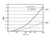
図4は、濃淡トナーの入力信号−濃度値特性の例を示したものである。ここではシアンと淡シアンについて図示しているが、マゼンタと淡マゼンタについても同様であるものとする。401はシアンの入力信号レベルに対する濃度値を示し、402は淡シアンの入力信号レベルに対する濃度値を示すものである。淡シアンとシアンはこのようなトナー濃度の関係にあるので、色分解部307で行われるC→C,LC色分解の典型的な例は、図5のようになる。図5において横軸は、入力となるシアン信号のレベル、縦軸に(淡シアンとシアンの)出力信号のレベルを取ってある。502に示すように、低濃度部では淡シアンの出力レベルが大きくなり、高濃度部に行くに従って、シアンの出力レベルを大きくするように制御する。淡シアンの出力レベルは、中濃度部から高濃度部にかけては、トナーの載り量の制限を守るために、減衰させていくようにする。ここでも色分解についてシアンと淡シアンについて説明したが、マゼンタと淡マゼンタについても同様である。
FIG. 4 shows an example of an input signal-density value characteristic of dark and light toner. Here, cyan and light cyan are illustrated, but the same applies to magenta and light magenta.
ここで、図6を用いて、プリンタ部100での階調表現方法について説明しておく。本実施形態の画像形成装置は、主走査、副走査とも600dpiの解像度を持ち、パルス幅変調方式(PWM)により、各画素256階調の階調表現能力を持つ。方式の概略を図6に示す。一画素周期で鋸状の波aを発生させ、各画素のレベルに応じた一画素周期の矩形波bとのしきい値処理を行うと、各画素のレベルに応じた幅の矩形波cが得られる。この幅により8ビットの階調表現を行う。プリンタ部100では、矩形波cのHighレベルに応じてレーザを発光させることにより、感光ドラム1aあるいは1bの表面上に所定サイズのドットが投影される。
Here, a gradation expression method in the
<スムージング処理部の構成>
特開平08−317210号公報などのエッジスムージング技術では、入力画像とのパターンマッチングを行ってあらかじめ登録されている特徴検出用パターンとマッチした場合にエッジをスムーズにするための画素の置き換えを行う技術が開示されている。図7は、そのような特徴検出用パターンの例を示したものである。図7において、特徴検出用パターンは9x9のビットマップからなり、その中心が注目画素(Mと表記する)である。一つの格子は600dpiの一画素一画素を表しており、「○」は画素が白ドット(=00H)であることを、「●」(=FFH)は画素が黒ドットであることを示す。その他の画素については黒ドットでも白ドットでも、あるいは中間調ドットでも構わない。
<Configuration of smoothing processing unit>
In the edge smoothing technique such as Japanese Patent Application Laid-Open No. 08-317210, a technique for performing pixel matching for an input image and replacing pixels for smoothing edges when matching with a pre-registered feature detection pattern is performed. Is disclosed. FIG. 7 shows an example of such a feature detection pattern. In FIG. 7, the feature detection pattern is a 9 × 9 bitmap, and the center thereof is the pixel of interest (denoted as M). One grid represents one pixel per pixel of 600 dpi, “◯” indicates that the pixel is a white dot (= 00H), and “●” (= FFH) indicates that the pixel is a black dot. Other pixels may be black dots, white dots, or halftone dots.
例えば、図7(a)のパターンと一致する入力画像では、注目画素Mは水平に近い斜線の一部でかつ高濃度部の変化点であるものと判断される。この結果、注目画素Mは、FFHからC0Hへと置き換えられる。次に、図7(b)のパターンと一致する入力画像では、注目画素Mは水平に近い斜線の一部でかつ低濃度部の変化点であると判断される。その結果、注目画素Mは、FFHから80Hへと置き換えられる。さらに、図7(c)のパターンと一致する入力画像では、注目画素Mは水平に近い斜線の一部かつ変化点から一ドット離れているので40Hに置き換えられる。結果として、このパターンとマッチした入力画像中の水平に近い斜線の上側のエッジでは、3画素で画素の置き換えが生じ、滑らかなエッジとなる。 For example, in the input image that matches the pattern of FIG. 7A, it is determined that the target pixel M is a part of a diagonal line near the horizontal and a change point of the high density portion. As a result, the target pixel M is replaced from FFH to C0H. Next, in the input image that matches the pattern of FIG. 7B, it is determined that the target pixel M is a part of the oblique line near the horizontal and the changing point of the low density portion. As a result, the target pixel M is replaced from FFH to 80H. Further, in the input image that matches the pattern of FIG. 7C, the target pixel M is replaced with 40H because it is part of the oblique line near the horizontal and one dot away from the changing point. As a result, at the edge on the upper side of the oblique line near the horizontal in the input image that matches this pattern, pixel replacement occurs in 3 pixels, resulting in a smooth edge.
このような特徴検出用パターンとパターンにマッチした際に置き換える画素値の対応付けを、ROMなどの記憶装置(メモリ204)に保持しておき、注目画素に対する処理を繰り返すことによって、エッジに対するスムージング効果を奏することが可能となる。図7で示した特徴検出用パターンは一例であり、特開平08−317210号公報や特開平10−42141号公報に開示されているようにさまざまなパターンのエッジの特徴を検出するためには、多数の特徴検出用パターンを保持している必要があるが、ここでは、説明の簡略化のため、それらのパターンを列挙することは行わない。 Such feature detection patterns and pixel values to be replaced when matched with the pattern are held in a storage device (memory 204) such as a ROM, and the processing for the pixel of interest is repeated, thereby smoothing the edge. It becomes possible to play. The feature detection pattern shown in FIG. 7 is an example. In order to detect edge features of various patterns as disclosed in Japanese Patent Application Laid-Open Nos. 08-317210 and 10-42141, Although it is necessary to hold a large number of feature detection patterns, these patterns are not listed here for the sake of simplicity.
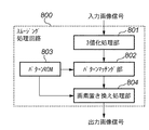
図8はスムージング処理部308を構成するスムージング処理回路の内部構成を示すブロック図である。スムージング処理部308によるスムージング処理は、このスムージング処理回路800により実行される。スムージング処理回路800は、入力画像をしきい値処理して、FFHと00Hとそれ以外とに分類する3値化処理部801、図7の特徴検出用パターンと置き換え画素値の対応を保持するパターンROM803、3値化処理された画像信号とパターンROM803から供給された特徴検出用パターンとのパターンマッチングを行うパターンマッチング部802、さらにパターンがマッチした際に画素の置き換えを行う画素置き換え処理部804を備える。ここで、3値化処理部801は、黒、白ドットを生成できればよく、2値化処理でも構わない。また、パターンマッチング部802で行われるマッチング処理では、例えば、パターンマッチング部802で入力された3値の画像信号と特徴検出用パターンの積和演算を行い、所定のしきい値を超えた場合にマッチしたとみなすマスク処理を行うものとする。
FIG. 8 is a block diagram showing an internal configuration of the smoothing processing circuit constituting the smoothing
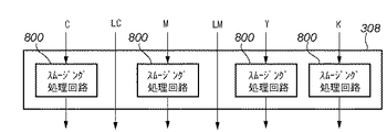
スムージング処理部308は、このように構成されたスムージング処理回路800をC,LC,M,LM,Y,Kの6色成分の各々について設けるのではなく、図9に示すように、C,M,Y,Kの色成分に対してのみ設けられる。即ち、LC,LMの色成分についてはスムージング処理を行わずにプリンタ部100へ送出する。なぜなら、図4に示したように、LC,LMは最大の入力信号レベルに対しても出力濃度はC,Mの40%ほどであり、画像中においてC,M信号が生じさせるようなエッジを生じさせることはないからである。
The smoothing
このような構成をとることにより、濃淡トナーを用いた画像形成装置においてエッジスムージング技術を適用する場合にも、色成分数の増加に対してスムージング処理回路の増加を防ぎ、コストの上昇を抑えることが可能である。また、淡色の画像信号についてスムージング処理を行わないようにし、他の色成分の画像信号についてはスムージングを施すので、スムージング効果は良好に維持できる。 By adopting such a configuration, even when edge smoothing technology is applied to an image forming apparatus using dark and light toner, an increase in the number of smoothing processing circuits can be prevented against an increase in the number of color components, and an increase in cost can be suppressed. Is possible. In addition, since the smoothing process is not performed on the light color image signal and the image signal of the other color components is smoothed, the smoothing effect can be maintained satisfactorily.
以上、説明したように、第1実施形態によれば、エッジスムージング技術を濃淡記録材(インク/トナー等)を用いる画像形成装置に適用した場合に、淡色信号に対するスムージング回路をあえて用いないことによって回路規模を削減し、安価でありながら、従来どおりのエッジスムージングの効果がある画像を出力することができる。なお、スムージング回路数の削減の観点からすれば、濃色と淡色に色分解する前のCMYKの4色の時点でスムージングを施すようにしてもよい。この場合、図3のスムージング処理部308を出力処理部305或いはガンマ補正部306の次段に配置することになる。ただし、図3を用いて説明したような濃色、淡色への色分解後のデータにスムージングを施す構成によれば、YMCKの4色の時点でスムージングを行うのに対して、エンジンに出力される信号により近い信号に対してエッジスムージングを行うことになる。したがって、スムージング処理によって形成された中間調ドットを色分解してしまうことによる不自然さを生じさせないという利点が期待できる。
As described above, according to the first embodiment, when the edge smoothing technique is applied to an image forming apparatus using a dark and light recording material (ink / toner, etc.), the smoothing circuit for the light color signal is not used. It is possible to output an image having an effect of edge smoothing as usual, while reducing the circuit scale and being inexpensive. From the viewpoint of reducing the number of smoothing circuits, smoothing may be performed at the time of four colors of CMYK before color separation into dark and light colors. In this case, the smoothing
[第2実施形態]
上記第1実施形態では、スムージング処理回路800において、画素の置き換えが発生した場合、その画素値は中間値(図7ではFFH→C0H,00H→80H,00H→40H)に置き換わる。第1実施形態では、画素の置き換えが発生した後には色成分間の相互作用がなく、濃記録材の中間値を用いて画素を置き換え、画像形成を行う構成となっている。しかしながら、特に電子写真方式のプリンタにおいては、中間調のドットは、信号レベルが小さくなればなるほどドットの形成が不安定となりやすい。そこで、第2実施形態では、濃記録材に対応した画像信号のスムージング後の画素置き換え信号を、さらに、濃記録材と淡記録材の組み合わせで画像形成される画像信号に置き換えることにより、画素置き換え信号のドット形成の安定化を図る。即ち、濃記録材に対応した画像信号にエッジスムージングを施したことにより新たに発生した中間調の信号を、濃淡の色材の組み合わせ、もしくは淡色の色材を用いて記録するように画像信号を変換する。
[Second Embodiment]
In the first embodiment, when pixel replacement occurs in the smoothing
第2実施形態では、スムージング処理部308を構成するスムージング処理回路900の構成を図10に示すようにし、スムージング処理部308の構成を図11に示すようにする。
In the second embodiment, the configuration of the smoothing
図10は、第2実施形態におけるスムージング処理回路の構成を示すブロック図である。第2実施形態のスムージング処理回路900は、シアンおよび淡シアン、あるいは、マゼンタおよび淡マゼンタの画像入力信号を入力とする(以下、シアン、マゼンタを総称して濃色画像信号、淡シアン、淡マゼンタを総称して淡色画像信号と呼ぶ)。濃色画像信号は、第1実施形態のスムージング回路800と同様に、3値化処理部801で3値化され、パターンマッチング部802でパターンROM903のパターンとのマッチングが行われて、画素置き換え処理部904に入力される。第2実施形態におけるスムージング処理回路900では、画素置き換え処理部904には、濃色画像信号のほかに淡色画像信号も入力されて、画素の置き換えが行われる。
FIG. 10 is a block diagram showing the configuration of the smoothing processing circuit in the second embodiment. The smoothing
画素の置き換えにおいては、色分解部307のような濃→濃淡色分解方式を適用することが考えられる。例えばシアンに関して、画素置き換え処理部904にて、置き換え信号として、C0H(=192),80H(=128),40H(=64)が得られたとすると、図5で示した濃→濃淡色分解によって、
濃信号 → 濃信号 + 淡信号
192 140 90
128 64 200
64 10 100
のように変換されて、濃色信号、淡色信号双方の注目画素Mの画素値を置き換える。上記処理により発生した淡色の信号は、入力された淡色画像信号に加えられて出力淡色画像信号となる。
In pixel replacement, it is conceivable to apply a dark-to-light color separation method such as the
Dark signal → Dark signal + Light signal 192 140 90
128 64 200
64 10 100
Thus, the pixel value of the target pixel M of both the dark color signal and the light color signal is replaced. The light color signal generated by the above processing is added to the input light color image signal to become an output light color image signal.
濃→濃淡色分解を行うには、画素置き換え処理部904内に1次元LUT変換を持てば実現できる。上記のように、特に、濃色信号の低濃度部の信号である64が淡色信号との組み合わせに置き換えることによって淡信号=100という信号値を用いて画素を形成することでき、ドット形成をより安定させることができる。
The dark-to-dark color separation can be realized if the pixel
あるいは、淡色信号のFFHに対応する濃度に相当する濃色信号の160(図4の濃度0.6に相当する)以下が画素置き換え信号として出力された場合には、濃色信号の0〜160を淡色信号の0〜255に均等に割り付けるような変換を行うようにして、淡色のみの画素値へ置き換える置き換え信号を生成してもよい。 Alternatively, when 160 or less of the dark color signal corresponding to the density corresponding to the FFH of the light color signal (corresponding to the density of 0.6 in FIG. 4) is output as the pixel replacement signal, 0 to 160 of the dark color signal. May be converted so as to be evenly assigned to 0 to 255 of the light color signal, and a replacement signal for replacing the pixel value with only the light color may be generated.
このような処理によって、濃色信号でドットが不安定な濃度域をより大きな信号値で画像形成できる淡色信号で置き換えることによって、画素周辺のスムージングのための中間調ドットの安定性を向上することができる。 By such processing, the stability of halftone dots for smoothing around pixels is improved by replacing dark areas where the dots are unstable with dark signals with light signals that can form images with larger signal values. Can do.
なお、本実施形態においては、濃淡信号に分解される色信号をシアン、マゼンタとして説明したが、ブラックやイエローに関しても濃色信号と淡色信号に分解して、同様のスムージング回路を適用し、現像器をさらに増やした画像形成装置に対する出力を行ってもよい。画像形成装置では、現像器が一つ増える場合には現像器の数は7個となるので、現像ロータリーに、現像器を3,4個ずつ配置すればよいし、現像器が2つ増える場合には、現像ロータリーに現像器を4個づつ配置すればよい。 In this embodiment, the color signals that are separated into light and dark signals are described as cyan and magenta. However, black and yellow are also decomposed into dark and light color signals, and a similar smoothing circuit is applied to develop them. The output may be performed on an image forming apparatus having more units. In the image forming apparatus, when one developing device is added, the number of developing devices is seven. Therefore, it is only necessary to arrange three or four developing devices in the developing rotary, and when two developing devices are added. In this case, four developing devices may be arranged in the developing rotary.
特に、ブラックに対しては、濃淡信号を併用したスムージング回路を適用して画像形成を行えば、黒い文字や細線ににおいて良好なスムージング効果が得られ、通常の文書で多く用いられる画像パターンに対して、スムージング効果の高い文書画像出力が得られる。即ち、モノクロ出力の画像形成装置にも効果的に適用できる。 In particular, for black, if an image is formed by applying a smoothing circuit that also uses a gray signal, a good smoothing effect can be obtained for black characters and fine lines. Thus, a document image output with a high smoothing effect can be obtained. That is, the present invention can be effectively applied to a monochrome output image forming apparatus.
以上のように、第2実施形態によれば、従来のエッジスムージング技術で不安定になりがちだった中間調ドットをより強度の高い淡色信号に置き換えるので、エッジ部の中間調濃度の安定性が高まり、より滑らかなエッジスムージング効果のある画像を出力することができる。 As described above, according to the second embodiment, halftone dots that tend to be unstable by the conventional edge smoothing technique are replaced with lighter color signals with higher intensity, so that the halftone density of the edge portion is stable. As a result, an image having a smoother edge smoothing effect can be output.
なお、第2実施形態では、エッジスムージング処理を濃色の画像信号に対してのみ行っているが、安定したドット形成の観点からすれば、濃淡全ての画像信号に対してエッジスムージング処理を行う構成にも第2実施形態の構成を適用することも可能である。 In the second embodiment, the edge smoothing process is performed only on the dark image signal. However, from the viewpoint of stable dot formation, the edge smoothing process is performed on all the light and dark image signals. It is also possible to apply the configuration of the second embodiment.
また、第1実施形態や第2実施形態において、階調表現方法としてPWM方式を用いるものとして説明したが、階調表現が2以上で8ビット未満のプリンタに対しても同様に適用される。この時には階調表現方法として、ディザ法や誤差拡散法などの擬似中間調表現方式を用い、擬似中間調表現された画像信号に対してスムージング処理を行えばよい。 In the first and second embodiments, the PWM method is used as the gradation expression method. However, the present invention is similarly applied to a printer having gradation expression of 2 or more and less than 8 bits. At this time, as a gradation expression method, a pseudo halftone expression method such as a dither method or an error diffusion method may be used, and smoothing processing may be performed on the image signal expressed in the pseudo halftone.
さらには、上記各実施形態では電子写真プリンタを画像形成装置の例としたが、濃淡インクを用いて画像形成を行うインクジェットプリンタに対しても、同様にエッジスムージング装置を用いた出力処理が可能であることは言うまでもない。 Furthermore, in each of the above embodiments, an electrophotographic printer is used as an example of an image forming apparatus. However, an output process using an edge smoothing device can be similarly applied to an inkjet printer that forms an image using dark and light inks. Needless to say.
Claims (5)
入力された画像信号より、前記複数の色材の各々に対応した色成分信号を生成する生成手段と、
前記生成手段で生成された色成分信号のうち、前記濃色の色材に対応した色成分信号についてエッジ部を検出し、検出されたエッジ部或いはその隣接部の画素の信号を、前記濃色の色材に対応した中間調の色成分信号に置き換えるエッジスムージング処理を施す平滑化手段と、
前記濃色の色材に対応した色成分信号に前記エッジスムージング処理を施すことにより発生した前記濃色の色材に対応した中間調の色成分信号を、該濃色と同系色の淡色の色材に対応した色成分信号に変換する変換手段と、
前記変換手段による変換によって得られた前記淡色の色材に対応した色成分信号を、前記生成手段で生成された当該淡色の色材に対応した色成分信号に加える加算手段とを備えることを特徴とする画像形成装置。 Image forming means for forming an image using a plurality of color materials including dark and light color materials of similar colors;
Generating means for generating a color component signal corresponding to each of the plurality of color materials from the input image signal;
Among the color component signals generated by the generation means, an edge portion is detected for a color component signal corresponding to the dark color material, and the detected edge portion or a pixel signal of the adjacent portion is detected as the dark color signal. Smoothing means for performing edge smoothing processing to replace with a halftone color component signal corresponding to the color material ;
A halftone color component signal corresponding to the dark color material generated by performing the edge smoothing process on the color component signal corresponding to the dark color material is a light color similar to the dark color. Conversion means for converting the color component signal corresponding to the material ;
Addition means for adding a color component signal corresponding to the light color material obtained by the conversion by the conversion means to a color component signal corresponding to the light color material generated by the generation means; An image forming apparatus.
前記濃色の色材に対応した色成分信号に前記エッジスムージング処理を施すことにより発生した前記濃色の色材に対応した中間調の色成分信号を、該濃色と同系色の淡色の色材に対応した色成分信号と該濃色の色材に対応した色成分信号とに変換し、
前記加算手段で加えることにより得られた淡色の色材に対応した色成分信号と、前記変換手段により得られた前記濃色の色材に対応した色成分信号とをプリンタ部に送出する送出部を有することを特徴とする請求項1に記載の画像形成装置。 The converting means includes
A halftone color component signal corresponding to the dark color material generated by performing the edge smoothing process on the color component signal corresponding to the dark color material is a light color similar to the dark color. A color component signal corresponding to the material and a color component signal corresponding to the dark color material,
A sending unit that sends the color component signal corresponding to the light color material obtained by adding by the adding unit and the color component signal corresponding to the dark color material obtained by the converting unit to the printer unit the image forming apparatus according to claim 1, characterized in that it comprises a.
画像形成手段が、同系色で濃色と淡色の色材を含む複数の色材を用いて画像形成を行う画像形成工程と、
生成手段が、入力された画像信号より、前記複数の色材の各々に対応した色成分信号を生成する生成工程と、
平滑化手段が、前記生成工程で生成された色成分信号のうち、前記濃色の色材に対応した色成分信号についてエッジ部を検出し、検出されたエッジ部或いはその隣接部の画素の信号を、前記濃色の色材に対応した中間調の色成分信号に置き換えるエッジスムージング処理を施す平滑化工程と、
変換手段が、前記濃色の色材に対応した色成分信号に前記エッジスムージング処理を施すことにより発生した前記濃色の色材に対応した中間調の色成分信号を、該濃色と同系色の淡色の色材に対応した色成分信号に変換する変換工程と、
加算手段が、前記変換工程における変換によって得られた前記淡色の色材に対応した色成分信号を、前記生成手段で生成された当該淡色の色材に対応した色成分信号に加える加算工程とを備えることを特徴とする画像形成方法。 An image forming method by an image forming apparatus,
An image forming step in which an image forming unit forms an image using a plurality of color materials including dark and light color materials of similar colors;
A generating step of generating a color component signal corresponding to each of the plurality of color materials from the input image signal;
The smoothing means detects an edge portion of the color component signal corresponding to the dark color material among the color component signals generated in the generation step, and the detected edge portion or a signal of a pixel in the adjacent portion thereof A smoothing step for performing an edge smoothing process for replacing a halftone color component signal corresponding to the dark color material ,
The conversion means converts a halftone color component signal corresponding to the dark color material generated by performing the edge smoothing process on the color component signal corresponding to the dark color material to a color similar to the dark color a conversion step of converting the color component signals corresponding to the color material of light color,
An addition step of adding a color component signal corresponding to the light color material obtained by the conversion in the conversion step to a color component signal corresponding to the light color material generated by the generation unit ; An image forming method comprising:
前記濃色の色材に対応した色成分信号に前記エッジスムージング処理を施すことにより発生した前記濃色の色材に対応した中間調の色成分信号を、該濃色と同系色の淡色の色材に対応した色成分信号と該濃色の色材に対応した色成分信号とに変換し、
前記加算工程で加えることにより得られた淡色の色材に対応した色成分信号と、前記変換手段により得られた前記濃色の色材に対応した色成分信号とをプリンタ部に送出する送出工程を有することを特徴とする請求項3に記載の画像形成方法。 In the conversion step,
A halftone color component signal corresponding to the dark color material generated by performing the edge smoothing process on the color component signal corresponding to the dark color material is a light color similar to the dark color. A color component signal corresponding to the material and a color component signal corresponding to the dark color material,
Sending step for sending the color component signal corresponding to the light color material obtained by adding in the adding step and the color component signal corresponding to the dark color material obtained by the converting means to the printer unit the image forming method according to claim 3, characterized in that it comprises a.
Priority Applications (3)
| Application Number | Priority Date | Filing Date | Title |
|---|---|---|---|
| JP2004093161A JP4006411B2 (en) | 2004-03-26 | 2004-03-26 | Image forming apparatus and method |
| US11/083,938 US7746504B2 (en) | 2004-03-26 | 2005-03-21 | Image forming apparatus and method which perform smoothing processing |
| CNB200510056994XA CN100435034C (en) | 2004-03-26 | 2005-03-25 | Image forming apparatus and method |
Applications Claiming Priority (1)
| Application Number | Priority Date | Filing Date | Title |
|---|---|---|---|
| JP2004093161A JP4006411B2 (en) | 2004-03-26 | 2004-03-26 | Image forming apparatus and method |
Publications (3)
| Publication Number | Publication Date |
|---|---|
| JP2005286391A JP2005286391A (en) | 2005-10-13 |
| JP2005286391A5 JP2005286391A5 (en) | 2007-03-01 |
| JP4006411B2 true JP4006411B2 (en) | 2007-11-14 |
Family
ID=34989468
Family Applications (1)
| Application Number | Title | Priority Date | Filing Date |
|---|---|---|---|
| JP2004093161A Expired - Fee Related JP4006411B2 (en) | 2004-03-26 | 2004-03-26 | Image forming apparatus and method |
Country Status (3)
| Country | Link |
|---|---|
| US (1) | US7746504B2 (en) |
| JP (1) | JP4006411B2 (en) |
| CN (1) | CN100435034C (en) |
Families Citing this family (14)
| Publication number | Priority date | Publication date | Assignee | Title |
|---|---|---|---|---|
| TWI278243B (en) * | 2005-07-28 | 2007-04-01 | Novatek Microelectronics Corp | Color smooth-adjustment device and adjustment method |
| JP2007043306A (en) * | 2005-08-01 | 2007-02-15 | Canon Inc | Image processing apparatus and processing method |
| US7532360B2 (en) * | 2005-09-16 | 2009-05-12 | Seiko Epson Corporation | Image output apparatus |
| US8064112B1 (en) * | 2007-05-20 | 2011-11-22 | Opaltone Australasia Pty. Ltd. | Color separation and reproduction method to control a printing process |
| JP5149690B2 (en) * | 2008-05-02 | 2013-02-20 | キヤノン株式会社 | Image processing apparatus, image processing method, and image processing program |
| JP5180670B2 (en) * | 2008-05-07 | 2013-04-10 | キヤノン株式会社 | Image processing apparatus and image processing method |
| JP2010039976A (en) * | 2008-08-08 | 2010-02-18 | Seiko Epson Corp | Image processor, printing data generation method, and computer program |
| US8092963B2 (en) * | 2010-01-19 | 2012-01-10 | Xerox Corporation | Toner compositions |
| KR101716278B1 (en) * | 2010-09-14 | 2017-03-27 | 에스프린팅솔루션 주식회사 | Image forming apparatus, printing control terminal apparatus and image forming method there of |
| JP5773749B2 (en) | 2011-05-19 | 2015-09-02 | キヤノン株式会社 | Color gamut compression method and profile generation apparatus using the same |
| CN104867109B (en) * | 2014-02-24 | 2018-08-10 | 联想(北京)有限公司 | A kind of display methods and electronic equipment |
| WO2016075961A1 (en) * | 2014-11-14 | 2016-05-19 | 株式会社沖データ・インフォテック | Inkjet printer |
| CN107206696B (en) * | 2015-01-30 | 2020-04-24 | 惠普发展公司有限责任合伙企业 | Three-dimensional object substructure |
| JP6703788B2 (en) * | 2016-07-11 | 2020-06-03 | キヤノン株式会社 | Image processing apparatus and image processing method |
Family Cites Families (15)
| Publication number | Priority date | Publication date | Assignee | Title |
|---|---|---|---|---|
| US4860026A (en) * | 1987-06-25 | 1989-08-22 | Canon Kabushiki Kaisha | Halftone image recording method using recording data having a plurality of concentrations for one color |
| JP2894137B2 (en) | 1993-01-26 | 1999-05-24 | ケイディディ株式会社 | Prefilter control method and apparatus in video coding |
| JPH0818785A (en) | 1994-04-28 | 1996-01-19 | Ricoh Co Ltd | Image output device |
| JPH08317210A (en) | 1995-05-23 | 1996-11-29 | Canon Inc | Image processing device and method therefor |
| CN1155104A (en) * | 1995-11-30 | 1997-07-23 | 株式会社东芝 | Image forming device |
| JP3492096B2 (en) | 1996-07-22 | 2004-02-03 | キヤノン株式会社 | Image processing device |
| US5946454A (en) * | 1996-08-15 | 1999-08-31 | Seiko Epson Corporation | Image enhancement during half-toning using low-pass and high-pass filtering |
| JPH10181000A (en) | 1996-12-26 | 1998-07-07 | Seiko Epson Corp | Method and device for ink jet recording |
| JPH1184764A (en) * | 1997-09-10 | 1999-03-30 | Fuji Xerox Co Ltd | Digital image forming method and device therefor |
| JP3728129B2 (en) * | 1999-02-09 | 2005-12-21 | キヤノン株式会社 | Image forming apparatus |
| KR100575975B1 (en) * | 1999-10-06 | 2006-05-02 | 삼성전자주식회사 | A circuit and method for multi-bit dithering image consistof gray data in lbp |
| JP2001318499A (en) | 2000-05-10 | 2001-11-16 | Konica Corp | Image forming device |
| JP2001290319A (en) | 2000-04-07 | 2001-10-19 | Konica Corp | Image forming device |
| US7164498B2 (en) * | 2002-06-20 | 2007-01-16 | Esko-Graphics A/S | Color matching for a printing process using more than four colorants using a four-colorant color management system |
| JP4012015B2 (en) | 2002-08-29 | 2007-11-21 | キヤノン株式会社 | Image forming apparatus |
-
2004
- 2004-03-26 JP JP2004093161A patent/JP4006411B2/en not_active Expired - Fee Related
-
2005
- 2005-03-21 US US11/083,938 patent/US7746504B2/en not_active Expired - Fee Related
- 2005-03-25 CN CNB200510056994XA patent/CN100435034C/en not_active Expired - Fee Related
Also Published As
| Publication number | Publication date |
|---|---|
| JP2005286391A (en) | 2005-10-13 |
| CN100435034C (en) | 2008-11-19 |
| CN1673882A (en) | 2005-09-28 |
| US7746504B2 (en) | 2010-06-29 |
| US20050213160A1 (en) | 2005-09-29 |
Similar Documents
| Publication | Publication Date | Title |
|---|---|---|
| US7746504B2 (en) | Image forming apparatus and method which perform smoothing processing | |
| US7990589B2 (en) | Image processing apparatus and method therefor | |
| US8077348B2 (en) | Information processing apparatus and its method therefore for printing an image with a first combination of process colors materials and a second combination of the process color materials and a spot color materials | |
| US20070046961A1 (en) | Image processing apparatus and method therefor | |
| US8218196B2 (en) | Image processing method and image processing apparatus | |
| US8121501B2 (en) | Image forming apparatus with color detection of a reference toner image and sheet | |
| US20070097439A1 (en) | Image processing method and apparatus thereof | |
| US7751086B2 (en) | Image processing apparatus and image processing method for generating image data for forming an image using a plurality of color materials of similar colors and different densities | |
| KR100905630B1 (en) | Image forming apparatus | |
| JP2007049338A (en) | Apparatus, method and program for processing color image | |
| US7551320B2 (en) | Image processing apparatus, image forming apparatus, control program, and computer-readable recording medium | |
| JP2000321925A (en) | Color image forming device | |
| JP2008107803A (en) | Image forming apparatus and image forming method | |
| JP3723043B2 (en) | Image processing apparatus, image reading apparatus, and image forming apparatus | |
| JP5305140B2 (en) | Image forming apparatus | |
| JP2005176035A (en) | Image processing apparatus | |
| JP4817663B2 (en) | Image forming apparatus | |
| JP2006166176A (en) | Image processor | |
| JP4956490B2 (en) | Image forming apparatus | |
| JP2007098771A (en) | Image forming apparatus, control program and computer readable recording medium | |
| JP2005252323A (en) | Apparatus and method for forming color image | |
| JPH07177365A (en) | Gradation processor for preventing irregular color | |
| JP4114801B2 (en) | Image forming apparatus and method | |
| JP2006229785A (en) | Image processing apparatus, image forming apparatus, image processing method, image processing program, and storage medium | |
| JP2007221566A (en) | Image forming apparatus and its image processing method |
Legal Events
| Date | Code | Title | Description |
|---|---|---|---|
| A521 | Request for written amendment filed |
Free format text: JAPANESE INTERMEDIATE CODE: A523 Effective date: 20070116 |
|
| A621 | Written request for application examination |
Free format text: JAPANESE INTERMEDIATE CODE: A621 Effective date: 20070116 |
|
| A871 | Explanation of circumstances concerning accelerated examination |
Free format text: JAPANESE INTERMEDIATE CODE: A871 Effective date: 20070116 |
|
| A131 | Notification of reasons for refusal |
Free format text: JAPANESE INTERMEDIATE CODE: A131 Effective date: 20070216 |
|
| A521 | Request for written amendment filed |
Free format text: JAPANESE INTERMEDIATE CODE: A523 Effective date: 20070413 |
|
| A131 | Notification of reasons for refusal |
Free format text: JAPANESE INTERMEDIATE CODE: A131 Effective date: 20070518 |
|
| A521 | Request for written amendment filed |
Free format text: JAPANESE INTERMEDIATE CODE: A523 Effective date: 20070717 |
|
| TRDD | Decision of grant or rejection written | ||
| A01 | Written decision to grant a patent or to grant a registration (utility model) |
Free format text: JAPANESE INTERMEDIATE CODE: A01 Effective date: 20070813 |
|
| A61 | First payment of annual fees (during grant procedure) |
Free format text: JAPANESE INTERMEDIATE CODE: A61 Effective date: 20070827 |
|
| R150 | Certificate of patent or registration of utility model |
Free format text: JAPANESE INTERMEDIATE CODE: R150 |
|
| FPAY | Renewal fee payment (event date is renewal date of database) |
Free format text: PAYMENT UNTIL: 20100831 Year of fee payment: 3 |
|
| FPAY | Renewal fee payment (event date is renewal date of database) |
Free format text: PAYMENT UNTIL: 20110831 Year of fee payment: 4 |
|
| FPAY | Renewal fee payment (event date is renewal date of database) |
Free format text: PAYMENT UNTIL: 20120831 Year of fee payment: 5 |
|
| FPAY | Renewal fee payment (event date is renewal date of database) |
Free format text: PAYMENT UNTIL: 20120831 Year of fee payment: 5 |
|
| FPAY | Renewal fee payment (event date is renewal date of database) |
Free format text: PAYMENT UNTIL: 20130831 Year of fee payment: 6 |
|
| LAPS | Cancellation because of no payment of annual fees |