JP4006225B2 - Inkjet recording apparatus and inkjet recording method - Google Patents
Inkjet recording apparatus and inkjet recording method Download PDFInfo
- Publication number
- JP4006225B2 JP4006225B2 JP2001352187A JP2001352187A JP4006225B2 JP 4006225 B2 JP4006225 B2 JP 4006225B2 JP 2001352187 A JP2001352187 A JP 2001352187A JP 2001352187 A JP2001352187 A JP 2001352187A JP 4006225 B2 JP4006225 B2 JP 4006225B2
- Authority
- JP
- Japan
- Prior art keywords
- recording
- ink
- paper
- recording medium
- mode
- Prior art date
- Legal status (The legal status is an assumption and is not a legal conclusion. Google has not performed a legal analysis and makes no representation as to the accuracy of the status listed.)
- Expired - Fee Related
Links
Images


Landscapes
- Ink Jet (AREA)
- Ink Jet Recording Methods And Recording Media Thereof (AREA)
Description
【0001】
【発明の属する技術分野】
本発明はインクジェット記録装置およびインクジェット記録方法に関し、詳しくは、記録紙など被記録媒体の記録特性を考慮した記録モードで記録を行なうことが可能なインクジェット記録装置およびインクジェット記録方法に関するものである。
【0002】
【従来の技術】
インクジェット記録方式は、低騒音、低ランニングコスト、高速での記録が可能であることや、装置の小型化、カラー化が容易であること等の種々の利点を有し、プリンタや複写機等において広く利用されている方式である。
【0003】
このようなインクジェット方式による記録装置では、特に、高速記録と高濃度記録の両立は従来からの主要な課題である。例えば、インクジェットプリンタでは、ドラフトモードという比較的高速の記録を行なうモードが知られているが、これはどちらかといえば記録品位をある程度犠牲にしたものである。具体的には、記録ドットを所定の割合で間引き、これに伴って、記録ヘッドの走査速度または記録ヘッドに対する被記録媒体の搬送速度を大きくするものである。このような間引きによる高速記録は、インクドットが被記録媒体に占める面積が全体的に小さくなり実現される濃度はそれ程高いものではない。
【0004】
一方、記録に用いる被記録媒体の記録特性の点から、上記の高速記録および高濃度記録に資する提案も種々なされている。一般的に、高濃度を実現するには被記録媒体のできるだけ表面近くの浅い部分にインクの染料等の色材を留めるのが重要である。一方、高速記録のためには、速やかなインク定着を促すため高い吸収性が求められる。しかし、この場合、インクの色材は被記録媒体の厚さ方向深く浸透しやすく表面に残る色材は少なくなり、高濃度は実現し難くなる。このように、被記録媒体の記録特性の点においても、高濃度記録と高速記録は両立し難い面がある。
【0005】
【発明が解決しようとする課題】
以上から明らかなとおり、被記録媒体として、多くの色材をその表面近くに留めることができ、かつインク溶媒を速やかに浸透して定着性がよいものは、上述した従来からの主要な課題を解決する上で求められるものの一つである。
【0006】
また、このような特別な被記録媒体に適した記録モードを実行し、高濃度記録と高速記録の両立を実現するとともに、その記録モードで、他の普通に用いられる被記録媒体に対しても高濃度記録と高速記録においてそれほど遜色のない記録を実現できることは、記録装置の使い勝手を向上させるなどの点で好ましいことでもある。例えば、ユーザが、文字などが主体の文書を記録しようとして故意に上述の特別な被記録媒体でなく通常用いられる普通紙を選択した場合や被記録媒体の選択を誤って普通紙などを用いた場合でも、高濃度かつ高速の記録を実現できれば、被記録媒体の種類を問わないユーザや記録する画像とそれに合った被記録媒体の選択を積極的に行なうユーザ等、多様なユーザに対応して常に良好な記録を行なうことが可能となる。
【0007】
本発明は、上述の課題を解決するためになされたものであり、その目的とするところは、被記録媒体として、多くの色材をその表面近くに留めることができ、かつインク溶媒を速やかに浸透させることが可能な被記録媒体を用い、これに適した記録モードで記録を行なうことを可能とし、また、使い勝手のよい記録装置を実現できるインクジェット記録装置およびインクジェット記録方法を提供することにある。
【0008】
【課題を解決するための手段】
そのために、本発明では、被記録媒体に対して記録ヘッドを相対移動させながら、前記被記録媒体に前記記録ヘッドから少なくともインクを吐出して記録を行うインクジェット記録装置において、普通紙に対して記録を行うための第1の記録モードと、同じインクで記録した場合に前記普通紙よりもにじみ率およびKa値が大きい所定の被記録媒体に対して記録を行うための第2の記録モードとを実行可能であり、前記第2の記録モードは、前記第1の記録モードに比べて、1画素当たりの最大インク打ち込み量が少なく且つ前記相対移動の速度が速いことを特徴とする。
【0009】
好ましくは、前記所定の被記録媒体は、アルミナ粒子を含有するものであることを特徴とする。
【0010】
さらに好ましくは、前記所定の被記録媒体は、サイズ剤を含有せず、且つ表面近傍にアルミナ粒子を含有するものことを特徴とする。
【0012】
また、被記録媒体に対して記録ヘッドを相対移動させながら、前記被記録媒体に前記記録ヘッドから少なくともインクを吐出して記録を行うインクジェット記録方法であって、普通紙に対して記録を行うための第1の記録モードと、前記普通紙よりもにじみ率およびKa値が大きい被記録媒体に対して記録を行うための第2の記録モードとを含む複数の記録モードの中から選択された記録モードで記録を行う工程を有し、前記第2の記録モードは、前記第1の記録モードに比べて、1画素当たりの最大インク打ち込み量が少なく且つ前記相対移動の速度が速いことを特徴とする。
【0016】
以上の構成によれば、普通紙よりもにじみ率およびKa値が大きい所定の被記録媒体に記録を行うための第2記録モードにおいては、普通紙に記録を行うための第1の記録モードに比べ、1画素当たりの最大インク打ち込み量を少なくし且つ相対移動の速度を速くする。ここで、好ましくは、上記所定の記録媒体として、アルミナ粒子を含有する被記録媒体、さらに好ましくは、上記所定の被記録媒体は、サイズ剤を含有せず、かつ表面近傍にアルミナ粒子を含有する被記録媒体、すなわち高速吸収紙を用いるので、インク打ち込み量が小さくてもインク色材は被記録媒体の表層に多くが留まり、また、インクの溶媒は比較的速く浸透する。これにより、上記記録モードでは、濃度が高くかつ高速の記録を行なうことができる。
【0017】
【発明の実施の形態】
以下、図面を参照して本発明の実施形態を詳細に説明する。
【0018】
本発明の一実施形態の特徴は、第一に被記録媒体である記録紙の記録特性にある。すなわち、インク溶媒を速やかに吸収できる吸収性を有し、かつインクの色材である顔料または染料を比較的浅い部分に多く留めることができる特性を有した記録紙を用いる点である。具体的には、この記録紙を用いた場合、インクは記録紙の表面に沿って比較的拡がるため、インク滴の量に対して、それによって形成されるドットの径の割合が比較的大きくなるとともに、被記録媒体の厚さ方向へは色材が浸透せずに表層の浅い部分に留まり、高い濃度を実現できるものである。その一方で、インク溶媒を速やかに記録紙の厚さ方向に浸透させ、高い定着性を示すものである。
【0019】
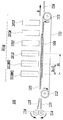
この記録特性を実現できる記録紙(以下では、「高速吸収紙」とも言う)は、本願発明者によって提案されたものであり、その概略構造は、図1に示すように記録紙表面の浅い部分にアルミナが含浸されたものである。なお、図1では記録紙の両面において施されているが、このアルミナの含浸は少なくともインクが吐出される面に施されていればよい。
【0020】
この高速吸収紙の構造は、後に詳述されるように、通常の記録紙を構成する繊維の表面にアルミナ粒子が吸着されたものであり、通常、滲み防止等の点から記録紙に用いられるサイズ剤は全く用いられていないか、用いてもごく微量である。この場合、サイズ剤が無い、あるいは微量であることによってインクはあらゆる方向において浸透しやすい。その結果として記録紙の表面に沿ってインクが広がり、インク量に比較して大きなドットを形成することができるが、アルミナ粒子が表層に存在するため、これを介してインクの顔料または染料が繊維に吸着され、これらの色材が記録紙の表層に多く留まることも可能としている。
【0021】
一方、サイズ剤が一切無いか、あるいは通常の記録紙に比べてはるかに微かな量が用いられている結果、通常、サイズ剤によって塞がれる各繊維間の空間は、ほぼそのままに空間として残り、インク溶剤はこの空間を通って記録紙の厚さ方向に浸透するができる。その結果、この高速吸収紙は高いインク吸収性もしくはインク定着性を可能とするものでもある。後述されるように、ブリストー法による測定では、通常のコピーなどで用いる記録紙に対して浸透性の低いインクである、いわゆる上乗せ系のインクを用いた場合でも、本実施形態の高速吸収紙は、Ka値で5ml・m-2・msec-1/2以上の高いインク吸収速度を示すものである。
【0022】
(高速吸収紙の実施形態)
本発明の一実施形態にかかる高速吸収紙の詳細について以下に説明する。本実施形態の高速吸収紙は、その紙表面が普通紙の風合いを呈している上に、上述したようにインク溶媒の吸収性が良く、かつインクによる記録領域の光学濃度が高いという特徴を有している。また、いわゆる粉落ちやカールが少ない、耐水性に優れた被記録媒体でもある。
【0023】
本願発明者らは、特許第2714350号〜同第2714352号それぞれの公報や、特開平9−99627号公報、同2000−211250号公報において、アルミナ水和物を繊維状物質に内添した被記録媒体を提案した。特許第2714350号〜同第2714352号の各公報、特開平9−99627号公報に開示されている被記録媒体は、特定物性値を示すアルミナ水和物を内添した被記録媒体であり、アルミナ水和物は繊維状物質全体に内添されている。この発明では非塗工紙でも良好な発色が得られることを見出した。さらに、特開2000−211250号公報に開示されている被記録媒体は、表面層と基層からなる多層構成の媒体であり、表面層のみにベーマイト構造を示すアルミナ水和物が内添された被記録媒体である。同発明ではアルミナ水和物を内添した被記録媒体を多層構成にして、表面層のみにアルミナ水和物を内添することと、基層を液体吸収性の良い材料で構成することで、高速記録時の発色、解像度が優れていることを見出した。
【0024】
本実施形態の被記録媒体は、それらの発明の改良であり、アルミナ水和物を内添した被記録媒体の構成を改良して、単層構成の被記録媒体であっても填料を含まない繊維状物質を用いて無サイズ紙を抄紙し、さらにアルミナ水和物とカチオン性樹脂を少なくとも繊維状物質の表面付近に存在させることで良好なインク吸収性と発色性、ドット再現性を得られることを見出しすことにより得られたものである。いわゆるフルラインヘッドなどを用いた超高速記録機で記録を行なう時に特に有効である。さらに好ましい形態は、上記無サイズ紙にアルミナ水和物とカチオン性樹脂をオンマシン塗工する形態である。
【0025】
本実施形態の被記録媒体は上記単層構成であり、アルミナ水和物とカチオン性樹脂をオンマシン塗工しているため通常の抄紙機で容易に製造することができ、生産性が著しく改善されていることも利点である。特に両面塗工を容易に行うことができると言う利点もある。本発明の適用において繊維状物質は紙に限定される必要はなく、合成パルプなどを用いた合成紙、布、不織布など繊維状の材料を使用した形態すべてに当てはまるものである。ここで無サイズ紙とはステキヒトサイズ度の測定で0秒であることを指している。ステキヒトサイズ度の測定はJIS P−8122の方法で行うことができる。
【0026】
つまり、本実施形態の被記録媒体は、填料を含まない単層構成のセルロース繊維を主体としていて、かつ無サイズの繊維状物質の少なくとも表面近傍にアルミナ水和物とカチオン性樹脂を存在させた被記録媒体である。この被記録媒体では、打ち込まれたインク中の色材は表面近傍で吸着され、インク中の溶媒成分は被記録媒体内部で吸収されるものである。填料を含まない無サイズ紙とすることで良好なインク吸収速度を得ることができる。
【0027】
本実施形態では填料を含まない繊維状物質を用いる。そして、繊維状物質の各繊維間の隙間には填料や顔料、樹脂などが存在しない。これは繊維状物質の隙間をなるべく残すことにより、インク吸収を最大限に良くするためである。そのために、本実施形態では通常の紙や布で用いられているサイズプレスなどの通常の樹脂成分の塗工は行わない。そしてこの繊維状物質の各繊維の表面にはアルミナ水和物とカチオン性樹脂が存在している。
【0028】
図2に示すように、具体的にはアルミナ水和物3とカチオン性樹脂4は、被記録媒体の各繊維1の表面を被服するように存在している。ここでアルミナ水和物またはカチオン性樹脂は繊維状物質の各繊維間の隙間2を埋めないように存在することが必要である。
【0029】
本実施形態においては、繊維状物質にアルミナ水和物とカチオン性樹脂を少なくとも表面近傍に存在させる。アルミナ水和物とカチオン性樹脂の添加方法としては繊維状物質に塗工することが好ましい。アルミナ水和物とカチオン性樹脂を塗工することによって表面近傍により多くのアルミナ水和物およびカチオン性樹脂を存在させることができて発色などが良くなる。さらに好ましい方法は、アルミナ水和物とカチオン性樹脂をオンマシン塗工する方法である。オンマシン塗工を行った場合はアルミナ水和物とカチオン性樹脂を繊維状物質の表面近傍にのみ存在せしめることができる。その理由は明らかでないが、オンマシン塗工の場合は、紙などが抄紙後直ちに塗工されるため繊維状物質の化学的・物理的な活性が高く接触したアルミナ水和物やカチオン性樹脂が付着してから繊維状物質に付着する時間が短いためと推測している。
【0030】
好ましい塗工量はそれぞれ片面あたり1〜5g/m2である。本実施形態ではサイズ塗工などのオンマシン塗工されているので両面同時に塗工される。その場合のアルミナ水和物とカチオン性樹脂の塗工量は両面でそれぞれ2〜10g/m2である。オンマシン塗工することで、少ない塗工量で、かつ普通紙の風合いを残したままでも良好な発色を得ることができる。ここで普通紙風とは表面にセルロース繊維が露出していて、手触りに微粒子などが塗工したような感じがないものを言う。また、オンマシン塗工とは特開平1−141783号公報や特開平11−174718号公報に記載されているように、抄紙工程でセルロース繊維上にサイズプレス塗工を行う代わりにアルミナ水和物とカチオン性樹脂をオンマシンで連続的に塗工するものである。この場合、紙の表面にサイズプレス層は存在していない。
【0031】
特開平1−141783号公報には、支持体上に無定形シリカと平均粒子径5〜200nmのアルミナ水和物を重量比で100:5〜100:35の割合で含む塗工液をオンマシンコーティングして得られたインクジェット用記録紙が開示されている。この発明では抄紙機上でのオンマシンコーティングでの生産性の向上を目的として塗工する無定形シリカのバインダーとしてアルミナゾルを用いている。本実施形態の被記録媒体とはオンマシンコーティングを行う点は一致しているが、本実施形態のような填料を含まない無サイズ紙にアルミナ水和物とカチオン性樹脂をオンマシン塗工する構成とは異なるものである。
【0032】
また、特開平11−174718号公報には、基紙の片面あたりに3〜8g/m2のピグメントサイズ塗工が施された用紙で、仕上げ密度が0.75〜0.90g/cm3の範囲、繊維配向比が1.05〜1.25の範囲、平滑度が50〜120秒の範囲、及び地合指数が20以上である情報用紙が開示されている。この発明ではフルカラー複写機のカラー画像を良好に保ちながら剛度を維持し、坪量を低減するために用紙の密度を低くしたときに定着されたトナーが紙の隙間に入り込むのを防止するためにピグメントサイズ塗工を行っている。本実施形態の被記録媒体とは特定範囲の紙にピグメントサイズ塗工を行う点では一致しているが、本実施形態のようにインク吸収性や発色、普通紙の風合いなどの特性を満足できるような特性である填料無添加の紙にアルミナ水和物とカチオン性樹脂をオンマシン塗工する思想は記載されていない。
【0033】
アルミナ水和物は、正電荷を持っているためインク中の染料などの色材の定着が良く、発色性に優れた画像が得られ、しかも黒色インクの茶変、耐光性などの問題点を生じないため、インクジェット記録用の被記録媒体に用いる材料としては好ましい。
【0034】
本実施形態の被記録媒体中に存在するアルミナ水和物としては、X線回折法でベーマイト構造を示すアルミナ水和物が、インク吸収性と及び色材の吸着性、発色性が良いので最も好ましい。アルミナ水和物は下記の一般式により定義される。
Al2O3-n(OH)2n・mH2O
式中、nは0〜3の整数の一つを表し、mは0ないし10、好ましくは0ないし5の値を示す。mH2 Oの表現は、多くの場合に結晶格子の形成に関与しない脱離可能な水相を表すものであり、そのために、mはまた整数でない値をとることもできる。ただし、mとnは同時にゼロにならない。
【0035】
一般に、ベーマイト構造を示すアルミナ水和物の結晶は、その(020)面が巨大平面を形成する層状化合物であり、X線回折図形に特有の回折ピークを示す。ベーマイト構造としては、完全ベーマイトの他に擬ベーマイトと称する、過剰な水を(020)面の層間に含んだ構造を取ることもできる。この擬ベーマイトのX線回折図形は完全ベーマイトよりもブロードな回折ピークを示す。完全ベーマイトと擬ベーマイトは明確に区別できるものではないので、本発明では特に断らない限り、両者を含めてベーマイト構造を示すアルミナ水和物という(以下、アルミナ水和物という)。
【0036】
本実施形態で用いられるベーマイト構造のアルミナ水和物としては、X線回折法でベーマイト構造を示すものが色濃度や解像度、インク吸収性が良いため好ましい。さらに、ベーマイト構造を示すアルミナ水和物であれば二酸化チタンやシリカなどの金属酸化物を含有したアルミナ水和物を用いることもできる。
【0037】
本実施形態で用いるアルミナ水和物の製造方法としては、特に限定されるものではないが、ベーマイト構造のアルミナ水和物を製造できる方法であれば、例えば、アルミニウムアルコキシドの加水分解、アルミン酸ナトリウムの加水分解などの公知の方法で製造することができる。また、特開昭56−120508号公報に開示されているように、X線回折的に無定形のアルミナ水和物を、水の存在下で50℃以上で加熱処理することによって、ベーマイト構造に変えて用いることができる。
【0038】
本実施形態の無サイズ紙セルロースパルプとしては特に制限はない。例えば、広葉樹材および針葉樹材から得られるサルファイトパルプ(SP)、アルカリパルプ(AP)、クラフトパルプ(KP)等の化学パルプ、セミケミカルパルプ、セミメカニカルパルプ、機械パルプ等、脱墨された二次繊維である故紙パルプが使用可能である。また、パルプは未漂白パルプ、漂白パルプの区別及び叩解、未叩解の区別なく使用可能である。また、セルロースパルプとしては、非木材パルプである草、葉、靱皮、種毛等の繊維、例えば、わら、竹、麻、バガス、ケナフ、みつまた、コットンリンター等のパルプも使用できる。本実施形態では填料を含まないことが必要である。さらに、ポリビニルアルコール、ポリアクリルアミド等の吸水性樹脂を含まないことが必要である。填料と吸水性樹脂を含まないことで記録ドットの良好な再現性を得ることができる。
【0039】
被記録媒体全体の坪量としては、坪量が少なくて被記録媒体が極端に薄くなければ特に制限はないが、40〜300g/m2の範囲がプリンターなどで記録する場合の搬送性の点で好ましい。さらに好ましい範囲は45〜200g/m2の範囲であり、紙の折り曲げ強度が高くならずに不透明度を高くすることができる。さらに多数枚記録サンプルを重ねた時に貼り付きが発生しにくくなる。
【0040】
本実施形態の被記録媒体では、上記セルロースパルプに加えて微細フィブリル化セルロース、結晶化セルロース、広葉樹または針葉樹を原料とする硫酸塩パルプ、亜硫酸塩パルプ、ソーダパルプ、ヘミセルラーゼ処理パルプ、酵素処理化学パルプを加えることが好ましい。これらのパルプの添加によって被記録媒体表面の平滑性が向上したり、地合いがよくなる効果がある上に、記録直後の被記録媒体表面のタックや膨潤変形がなくなる効果もある。
【0041】
本実施形態では上記セルロースパルプに加えて嵩高性セルロース繊維、マーセル化されたセルロース、フラッフ化セルロース、サーモメカニカルパルプなどの機械パルプなどを添加して用いることができる。これらのパルプの添加によって被記録媒体のインク吸収速度、インク吸収量を向上させることができる。
【0042】
本実施形態では、被記録媒体のインク吸収速度は公知の動的走査吸液計によって測定することができる。本実施形態の被記録媒体は液体に対して接触時間が25ミリ秒で50ml/m2以上の吸収量であることが好ましい。この範囲内であればインク組成によらずにビーディングの発生が防止できるという効果がある。さらに接触時間が100ミリ秒で100ml/m2以上の吸収量であることが好ましい。この範囲であれば高速で多重記録する場合でもにじみやはじき、ビーディングの発生を防止することができる。
【0043】
液体の吸収速度、吸収量は用いるセルロースパルプの種類、叩解度によって目的の値に制御することが可能である。本実施形態の被記録媒体では上記嵩高性セルロース、マーセル化セルロース、フラッフ化セルロース、機械パルプの添加で特に吸収性を向上させることができる。さらに、フィブリル化セルロース、結晶化セルロース、硫酸塩パルプ、亜硫酸塩パルプ、ソーダパルプ、ヘミセルラーゼ処理パルプ、酵素処理された化学パルプを加えることで被記録媒体の表面性を改善することができる。
【0044】
本実施形態の被記録媒体の製造方法は一般的に用いられている紙の製造方法を用いることができる。抄紙装置としては従来から用いられている長網抄紙機、丸網抄紙機、円胴、ツインワイヤーなどから選択して用いることが出来る。
【0045】
本実施形態では、通常の紙の製造方法で行われるサイズプレス工程でのデンプンなどの塗工は行わない。その代わりにアルミナ水和物とカチオン性樹脂をオンマシン塗設する。オンマシン塗工の方法としては一般的な塗工方法を選択して用いることができる。例えばゲートロールコーター、サイズプレス、バーコーター、ブレードコーター、エアナイフコーター、ロールコーターブラッシュコーター、カーテンコーター、グラビアコーター、スプレー装置等による塗工技術を採用することができる。アルミナ水和物とカチオン性樹脂は混合して塗工する方法、それぞれ独立してオンマシン塗工する方法の中から自由に選択して行うことができる。
【0046】
本実施形態では、オンマシン塗工された被記録媒体に必要に応じてカレンダー処理やスーパーカレンダー処理を行って表面を平滑にすることができる。
【0047】
本実施形態で用いられるアルミナ水和物はベーマイト構造のアルミナ水和物であるが、X線回折法でベーマイト構造を示すものであれば、二酸化チタンやシリカなどの金属酸化物を含有したアルミナ水和物を用いることもできる。二酸化チタンを含有するベーマイト構造のアルミナ水和物としては例えば特許第2714351号公報に記載されたものを用いることができる。シリカを含有したベーマイト構造のアルミナ水和物としては例えば特開2000−79755号公報に記載されたものを用いることができる。別な形態としては、二酸化チタンやシリカの代わりにマグネシウム、カルシウム、ストロンチウム、バリウム、亜鉛、硼素、シリコン、ゲルマニウム、錫、鉛、ジルコニウム、インジウム、燐、バナジウム、ニオブ、タンタル、クロム、モリブデン、タングステン、マンガン、鉄、コバルト、ニッケル、ルテニウムなどの酸化物を含有させて用いることもできる。
【0048】
アルミナ水和物の形状(粒子形、粒子径、アスペクト比)は、アルミナ水和物をイオン交換水に分散させてコロジオン膜上に滴下して測定用試料を作り、この試料を透過型電子顕微鏡で観察することによって測定することができる。アルミナ水和物の中で擬ベーマイトには、前記文献(Rocek J.、et al、Applied Catalysis、74巻、29〜36頁、1991年)に記載されたように、繊毛状とそれ以外の形状が有ることが一般に知られている。本発明においては繊毛状または平板形状のどちらの形状のアルミナ水和物でも用いることができる。
【0049】
平板形状の粒子のアスペクト比は、例えば特公平5−16015号公報に定義されている方法で求めることができる。アスペクト比は粒子の厚さに対する直径の比を示す。ここで直径とは、アルミナ水和物を顕微鏡または電子顕微鏡で観察したときの粒子の投影面積と等しい面積を有する円の直径を示すものとする。縦横比はアスペクト比と同じように観察して、平板面の最小値を示す直径と最大値を示す直径の比である。また、毛状束形状の場合には、アスペクト比を求める方法は、毛状束を形成するアルミナ水和物の個々の針状粒子を円柱として上下の円の直径と長さをそれぞれ求めて、直径に対する長さの比をとって求めることができる。最も好ましいアルミナ水和物の形状は、平板状では平均アスペクト比が3〜10の範囲で、平均粒子直径が1〜50nmの範囲が好ましく、毛状束では平均アスペクト比が3〜10の範囲で、平均粒子長さが1〜50nmの範囲が好ましい。平均アスペクト比が上記範囲であれば、インク受容層を形成した時や繊維状物質に内添した時に粒子間に隙間が形成されるため、細孔半径分布の幅広い多孔質構造を容易に形成することができる。平均粒子直径または平均粒子長さが上記範囲内であれば、同様に細孔容積の大きな多孔質構造を作ることができる。
【0050】
本実施形態のアルミナ水和物のBET比表面積は70〜300m2/gの範囲が好ましい。BET比表面積が上記範囲よりも小さい場合には、記録された画像が白濁したり、画像の耐水性が不十分になる。BET比表面積が上記範囲よりも大きい場合には、粉落ちが発生し易くなる。アルミナ水和物のBET比表面積、細孔半径分布、細孔容積は窒素吸着脱離方法によって求めることができる。
【0051】
被記録媒体中のアルミナ水和物の結晶構造は一般的なX線回折法によって測定することができる。アルミナ水和物を内添した被記録媒体を測定セルに取り付けて回折角度2θが14〜15°に現れる(020)面のピークを測定して、ピークの回折角度2θと半値幅Bから、(020)面の面間隔はブラッグ(Bragg)の式、(010)面に垂直方向の結晶厚さはシェラー(Scherrer)の式を用いて求めることができる。
【0052】
被記録媒体中のアルミナ水和物の(020)面の面間隔は、0.617nmを越え0.620nm以下である範囲が好ましい。この範囲では使用する染料などの色材の選択幅が広くなり、疎水性、親水性のどちらの色材を用いて記録しても、記録部の光学濃度が高くなり、かつ滲みやビーディング、はじきの発生が少なくなる。また、疎水性、親水性の色材を併用して記録しても、光学濃度やドット径が色材の種類によらず均一になる。また、インク中に親水性または疎水性の材料を含んでいても記録部の光学濃度やドット径の変化がなく、滲みやビーディング、はじきの発生が少なくなる。(010)面に垂直方向の結晶厚さは6.0〜10.0nmの範囲が好ましい。この範囲では被記録媒体のインク吸収性及び色材の吸着性が良く、粉落ちが少なくなる。被記録媒体中のアルミナ水和物の(020)面の面間隔と(010)面に垂直方向の結晶厚さを上記範囲内にする方法は例えば特開平9−99627号公報に記載された方法を用いることができる。
【0053】
被記録媒体中のアルミナ水和物の結晶化度は同様にX線回折法によって求めることができる。アルミナ水和物を内添した被記録媒体を粉末化して測定セルに取り付け、回折角度2θが10°における強度と2θが14〜15°に現れる(020)面のピークを測定して、2θ=10°のピーク強度に対する(020)面のピーク強度から結晶化度を求めることができる。被記録媒体中のアルミナ水和物の結晶化度は15〜80の範囲が好ましい。この範囲内であればインク吸収性が良くなる上に記録された画像の耐水性が良くなる。被記録媒体中のアルミナ水和物の結晶化度を上記範囲内にする方法は例えば特開平8−132731号公報に記載された方法を用いることができる。
【0054】
用いるアルミナ水和物の好ましい細孔構造は以下の3種類あり、必要に応じて1種類以上選択して用いることができる。
【0055】
第1の細孔構造は、上記アルミナ水和物の平均細孔半径は2.0〜20.0nmで、細孔半径分布の半値幅は2.0〜15.0nmのものである。ここで平均細孔半径は、特開昭51−38298号公報、特開平4−202011号公報などに示されるものである。また、細孔半径分布の半値幅とは、細孔径分布の測定結果において平均細孔半径の頻度の半分の頻度である細孔半径の幅を示すものである。
【0056】
上記範囲の平均細孔半径と半値幅であれば、使用できる色材の選択幅が広くなって疎水性や親水性の色材を用いても滲みやビーディング、はじきがほとんど発生せず、光学濃度やドット径が均一になる。上記細孔構造を持つアルミナ水和物は、例えば特許第2714352号公報に記載された方法で作ることができる。
【0057】
第2の細孔構造は、上記アルミナ水和物が細孔半径分布において半径10.0nm以下と半径10.0〜20.0nmの範囲にそれぞれ極大を持っているものである。半径10.0〜20.0nmの比較的大きい細孔でインク中の溶媒成分を吸収し、半径10.0nm以下の比較的小さい細孔でインク中の色材などの色材成分を吸着する。そのため、色材の吸着と溶媒の吸収の両方とも早くなる。半径10.0nm以下の極大は半径1.0〜6.0nmにあるものがより好ましく、この範囲内では色材の吸着が早くなる。細孔半径10.0nm以下の極大部分の細孔容積比(極大2の容積比)は、全細孔容積の0.1〜10%であることがインク吸収性と色材定着性の両者を満足するため好ましく、より好ましくは1〜5%の範囲であり、この範囲ではインク吸収速度と色材の吸着速度が早くなる。上記細孔構造を持つアルミナ水和物は例えば特許第2714350号に記載された方法で作ることができる。それ以外の方法として半径10.0nmにピークを持つアルミナ水和物と半径10.0と20.0の間にピークを持つアルミナ水和物を併用する方法を用いることができる。
【0058】
第3の細孔構造は、上記アルミナ水和物が細孔半径分布において半径2.0〜20.0nmの範囲に最大ピークを持つものである。この範囲にピークを持つとインク吸収性と色材吸着の両方を満足し、かつアルミナ水和物の透明性が良くなり、画像の白濁を防止することができる。最大ピークのさらに好ましい範囲6.0〜20.0nmで、この範囲内であれば色材として顔料を用いたインク、染料を用いたインク、染料インクと顔料インクの併用インク、混合インクのどちらのインクで記録を行っても、滲み、はじき、色むらの発生を防ぐことができる。最も好ましい範囲は半径6.0〜16.0nmの範囲である。この範囲内であれば色材濃度の異なる3種類以上のインクを用いた場合でも濃度による色味の差異がなくなる。上記細孔構造を持つアルミナ水和物は例えば特開平9−6664号公報に記載された方法で作ることができる。
【0059】
アルミナ水和物の全細孔容積は0.4〜1.0cm3/gの範囲が好ましい。この範囲内であればインク吸収性が良い上に多色記録を行っても色味が損なわれることがない。さらに、0.4〜0.6cm3/gの範囲であることが粉落ちや画像のにじみが発生しにくくなるため好ましい。さらにアルミナ水和物の半径2.0〜20.0nmの範囲の細孔容積が全細孔容積の80%以上であると、記録された画像に白濁が発生しないのでさらに好ましい。別な形態としてアルミナ水和物を凝集させて用いることも可能である。粒子径が0.5〜50μmでBET比表面積/細孔容積の値が50〜500m2/mlである範囲が好ましい。この範囲内であればアルミナ粒子の吸着点が数多く露出しているために記録環境(温度、湿度)によらずビーディングの発生を防ぐことができる。上記細孔構造を持つ凝集粒子は、例えば特開平8−174993号公報に記載された方法を用いることができる。
【0060】
また、本実施形態において、カップリング剤処理されたアルミナ水和物を用いることができる。用いるカップリング剤としてはシラン系、チタネート系、アルミニウム系、ジルコニウム系カップリング剤の中から1種類以上選択して用いることができる。カップリング剤によってアルミナ水和物が疎水化されていると画像の色濃度が高く、鮮明な画像が得られるので好ましい。アルミナ水和物全体の表面積換算で0.1〜30%の範囲でカップリング剤処理されていると、インクの吸収性を損なうことなく、発色性を高めることができる。上記カップリング剤処理方法は例えば特開平9−76628号に記載された方法で行うことができる。
【0061】
さらに本実施形態では、アルミナ水和物に金属アルコキシド、水酸基を架橋することができる物質を添加して用いることも可能である。金属アルコキシドとしては例えばテトラエトキシシラン、テトラメトキシシランのように一般に用いられている材料の中から自由に選択して用いることができる。水酸基を架橋することができる材料としては例えば硼酸または硼酸化合物、ホルマリン化合物などの中から自由に選択して用いることができる。処理方法は例えば特開平9−86035号公報に記載された方法を用いることができる。これらの材料を添加することで、界面活性剤を多く添加した浸透性の良いインクを用いて記録した場合でも、滲みやビーディングの発生を防止することができる。
【0062】
本実施形態で用いるカチオン性樹脂としては、4級アンモニウム塩、ポリアミン、アルキルアミン、ハロゲン化第4級アンモニウム塩、カチオン性ウレタン樹脂、塩化ベンザルコニウム、塩化ベンゼトニウム、ジメチルジアリルアンモニウムクロライド重合物などの材料の中から自由に選択して用いることができる。
【0063】
本実施形態で用いられる高速吸収紙としての被記録媒体には、無機塩を含有させても良い。この場合、インクとして顔料インクを用いると、発色等が良く、より好ましい。
【0064】
無機塩としては、特に水溶性セリウム化合物が好ましい。水溶性セリウム化合物であればどの材料でも使用することができる。
【0065】
この被記録媒体に水性インクで記録を行った場合には、インク液滴が被記録媒体に到達すると水溶性セリウム化合物が溶解してインク液滴と混じり合う。そしてインク液滴中の顔料色材またはインク中に存在している水溶性高分子やエマルジョン、あるいはマイクロカプセル化された色材に作用して色材を定着させる。水溶性セリウム化合物の色材などの定着速度は非常に早く、最近の高速記録のプリンターやフルラインヘッドを持ったプリンターでも十分に定着を行うことができるため、文字などの細線の解像度が高い上にべた記録部のむらが発生しにくいという利点がある。この効果は、従来のカチオン性樹脂の添加や他の金属塩の添加では得られなかった効果である。特に、全色顔料インクを用いたプリンターで記録した場合にその効果が顕著に現れる。白地に文字を記録した場合と、べた記録部に文字を記録した場合には、一般的な被記録媒体ではべた記録部上では文字の輪郭に鮮明性が得られないのに対して、本実施形態の被記録媒体ではべた記録部上の文字などの細線でも、白地と同等の鮮明性が得られる。また海の波や肌色などの色調や濃度が微妙に変化するような画像でも忠実性の良い画像を得ることができる。
【0066】
本実施形態では水溶性セリウム化合物の中では塩化セリウムなどのセリウムハロゲン化物がより好ましい。セリウムのハロゲン化物は記録された時のインク液中への拡散速度が速いのと被記録媒体を保存する時にべた付きや着色が発生しにくいという効果がある。さらに好ましい水溶性セリウム化合物は粗塩化希土である。粗塩化希土は鉱物資源として取り出される希土類の鉱物から目的の希土類を取り出した残さである。主成分は塩化セリウムである。粗塩化希土は天然物であるために経口毒性が低いなどの安全性が高い上に材料自体が安価であるという効果がある。さらに染料インクを用いて記録した画像の光安定性が良くなるという効果もある。
【0067】
本実施形態の水溶性セリウム化合物の被記録媒体への添加量には画像の観点では特に制限はない。好ましい添加量はインク受容層を持つ構成、基材単独の構成ともに0.01g/m2以上10.0g/m2が好ましい。この範囲内であれば水性インクで記録を行った時に高濃度の発色が選られる。さらに好ましい範囲は0.1g/m2以上7.0g/m2である。この範囲内であればべた記録部の均一性と細線のにじみの防止が可能である。
【0068】
上述した高速吸収紙の製造方法の一例は、通常の記録紙を製造する行程における、紙にサイズ剤を含浸する工程の代わりに、アルミナ分散剤液等を含浸させる工程を設けることによって行われる。すなわち、アルミナ分散剤液の中に紙を浸し、その分散剤液の温度や浸す時間などを制御することによってアルミナの含浸量を調節している。図1に示すように、紙の両面に対してアルミナ粒子が分布するのは、上記の含浸工程によるものである。この工程により、特に、紙の表層近傍において、アルミナ粒子の密度が高くなるが、層構造にはならないため、大量のインクが打ち込まれても、高速に浸透することが可能となる。
【0069】
(インク打ち込み量の実施形態)
上述の高速吸収紙を用いてインクジェット方式の記録を行う場合、1画素当たりの打ち込み量(吐出量)を少ないものとすることができる。ここで、打込み量制御を行なうときの“1画素当りのインク打込み量”とは、ある1つの色のインクにおける最大の打込み量を意味する。すなわち、例えばシアン(C)インクで一様な階調のパターンを印字する場合に、最大濃度が測定される階調のパターンを印字したときにそのパターンに打込まれたインク量を、そのパターンの面積で割ったものということができる。従って、この打込み量は、例えば、1画素に対して8plの液滴を2滴まで打込めるような記録装置の構成で、1.5滴というような小数で表されることもある。
【0070】
図9を参照して、記録装置におけるこの打込み量制御の一例を説明する。図9は、ガンマ補正を行なうガンマテーブルの内容を示す図である。
【0071】
このテーブルを用いたガンマ補正によって、8ビットデータの入力値が255に対して出力値が255となるとき、1画素に最大2滴を打込むことができる記録装置において、打込み量制御として、入力値255に対して出力値が192となるような、図9に示すガンマテーブルを用いる。そして、その出力値を誤差拡散処理などにより量子化して記録データを得、このデータに基づいたインク吐出による記録を行なうと、ガンマテーブルに入力する濃度データが最大の255のときに記録されるパターンにおいて上記のように定義される打込み量を1画素当り(平均)1.5滴とすることができる。また、インク打ち込み量は、1滴の適量を変調することによっても可能である。なお、上記に限らず、1画素に対して例えば2滴のインクを打ち込むところを1滴のみ打ち込むことにしてもよい。こうすることにより、画像データの欠落がなく、より高品位の画像を得ることができる。
【0072】
本願発明者らの検討によれば、高速吸収紙の場合、インク打ち込み量が、600dpiの1画素に対して、5pl〜15plの量で十分なドット径と濃度を得ることができる。すなわち、記録紙の単位面積当たり、約2.8×10⁻³pl/μm2〜約8.4×10-3pl/μm2の打ち込み量で十分な画像濃度を得ることができる。打ちこみ量が逆に多すぎる場合は、打ち込まれたインクがドットの周囲においてにじみとなって表れ易くなるため、記録画像の輪郭部であるエッジのシャープネスが劣化することがある。特に、カラー染料インクの場合、高速吸収紙に対する打ち込み量は、1画素当たり、4pl〜10plで十分である。すなわち、記録紙の単位面積当たり、2.2×10-3pl/μm2〜5.6×10-3pl/μm2で良い。
【0073】
例えば、1画素当たり、8plで記録した場合のドット径は、顔料を含んだブラック(Bk)インクで約60μm、カラー染料インクで約80μmとなる。この場合、にじみ率は顔料のBkインクで約2.3、カラー染料インクで約3.1となる。このように、高速吸収紙は、インクの種類を選ばずにじみ率を大きくできるものであり、これにより、比較的少ないインク打ち込み量で、色材が表層の浅い部分に留まるのと相俟って高濃度な記録画像を可能としている。
【0074】
ここで、にじみ率とは、インク滴を球体とした場合の直径をその体積から換算し、その直径に対して被記録媒体上でのドット径がどの程度の倍率となって広がるかを表す場合の倍率に相当する。
【0075】
顔料インクを用いた場合、顔料はインク溶剤に比べ記録紙表面で拡散しにくいためか、染料に比べてドット径はそれ程大きくはならないが、上述の通り記録紙の表面でアルミナと顔料が反応して凝集・吸着することにより濃度、エッジシャープネスが向上することを可能としている。また、高速吸収紙に、カチオン高分子や無機塩等が加えられと、なお濃度向上の点で好ましい。染料インクの場合も、染料がアルミナ粒子に吸着するため、特に、べた記録部の濃度を高くすることができる。その濃度値はインクの種類や染料の濃度によっても多少変わるが、いずれにしても濃度は高くなる。
【0076】
本実施形態の高速吸収紙は、染料インクの場合は、にじみ率を2.5以上に調整することが好ましく、顔料インクの場合は2.0以上に調整することが好ましい。
【0077】
これに対し、通常用いられる、コピー用紙などの普通紙は、にじみ率はそれほど大きくなく、浸透性の低いいわゆる上乗せ系の染料インクでは2倍程度、浸透性の高いインクで2.6倍程度となる。
【0078】
(ドット形成の実施形態)
図3(a)〜3(d)は、上述した高速吸収紙の特徴である色材を比較的表層部分に留め、また、その表層に沿ったインクの浸透により比較的大きなドットを形成できるとともに、インク溶媒の被記録媒体の厚さ方向への浸透が速やかに行なわれる点について、普通紙と比較して説明する図である。同図には、高速吸収紙と普通紙に対し、種々のインクを打ち込んだときのインクドットの形成過程が示される。
【0079】
図3(a)〜3(d)に示すように、高速吸収紙および普通紙に対して、記録ヘッドから吐出されたインク滴はこれらの被記録媒体に着弾すると(着弾時:t0)、吐出インク滴の直径に対しておよそ2倍程度の直径を有した柱状のインク滴が形成される。
【0080】
高速吸収紙の場合、上述したようにサイズ剤が基本的に含有されていないか、含有されていても微量であるため、所定時間(t1)が経過すると、図3(b)および3(d)に示すように、紙のあらゆる方向に対して比較的速くインクが浸透する。このメカニズムは、インクが普通紙に対して浸透性がそれ程よくない、いわゆる上乗せ系であっても同じである。そして、この紙の表面においても、インクの紙に対する濡れ性が高いことと相俟って、紙表層に沿った横方向にも速く浸透し、ドット径は大きくなる。これに対し、普通紙の場合は、図3(c)に示すように、インクが上乗せ系である場合には、横方向の広がりは小さくドット径はそれ程大きくならない。
【0081】
さらに時間が経過すると(t2)、インクの浸透は進行するが、高速吸収紙の場合、表層部にアルミナ粒子が含まれているため、インク中の色材がアルミナ粒子に吸着し、図3(b)および3(d)に示すように、紙のごく浅い領域に色材が固定化される。同時に、インク中の水性溶媒は、染料等の色材と分離して、繊維間の空間部を通って紙中に浸透する。一方、普通紙の場合、図3(a)に示す、その浸透性インクとの組合せに示されるように、インクの色材が記録紙の深さ方向に溶媒と共に浸透してしまい、結果として色材が紙の表層に留まる量は少なくなる。
【0082】
以上のドット形成メカニズムにおいて、最終的に得られるドット径は、図3(a)に示す径D1と図3(b)に示す径D2とが略等しく、径D1は図3(c)に示す径D3より大きく、さらに、径D2は図3(d)に示す径D4より大きいという関係がある。
【0083】
なお、前述したように、高速吸収紙に、カチオン高分子や無機塩等が含まれていると、特に、顔料インクを用いた場合、上記の程度はより顕著となり、濃度やエッジシャープネスが向上して好ましい。
【0084】
(装置構成の実施形態1)
吐出部となる記録ヘッドは、ブラック(以下、単にBkともいう)、シアン(以下、単にCともいう)、マゼンタ(以下、単にMともいう)、イエロー(以下、単にYともいう)のインクと処理液(以下、単にSともいう)をそれぞれ吐出するものである。
【0085】
普通紙に記録する場合においては、少なくともBkの画像はBkインクと処理液を被記録媒体上で混合、反応させることで形成させる。具体的にはBkインクを被記録媒体に付与し、引き続き処理液を付与する場合と、処理液を先に付与し、次いでBkインクを付与する場合がある。これによって、Bk画像は濃度の高い品位の良いものとなる。さらに、Bkインクとして、顔料を用いると濃度が高く、好ましい。
【0086】
カラーインクに関しては、処理液との反応、あるいはインク単独で用いられる。処理液及びカラーインクを、浸透性の高いものを用いることで、Bk画像、カラー画像とも定着性の速いものとすることができ、高速記録が可能となり、好ましい。
【0087】
高速吸収紙に記録を行う場合においては、上述したように、各インク及び処理液を普通紙の記録モードに比較して、1画素に対する液滴の打ち込み量を少なくする。たとえば、600DPIの1画素に対して、Bkインクを普通紙モードでは2発打ち込み、高速吸収紙モードでは1発にする。
【0088】
同様に、処理液は、普通紙記録モードで1発、高速吸収紙記録モードでは、0.5発にする。
【0089】
このように高速吸収紙記録モードでは、普通紙記録モードに対して、打ち込まれる液滴の数を少なくしているにも関わらず、高速吸収紙では、普通紙に比べてドットも大きく、濃度も高いため、高画質な画像を得ることができる。
【0090】
また、上記のように、少ないドットで画像が形成できるため、記録ヘッドの駆動周波数を高く設定すること、あるいは走査速度もしくは記録紙の搬送速度を大きくすることも可能となり、記録装置として高速記録が可能となる。
【0091】
一方、このように記録装置で速く記録されたものが、記録紙で速く吸収定着されるため、排紙されたものから、インクが他に移るという心配も発生しない。よって、本質的に高速な記録が可能となる。
【0092】
また、普通紙に対してよりも、インクの打ち込み量を少なくすることで、この高速吸収紙の表面に色材がトラップされやすいことと相まって、紙の記録面の裏側での濃度が小さくなる、いわゆる、裏抜けを起こしにくい。さらに、インク打ち込み量が少ないため、インクによる紙の膨潤に伴うコックリングも、軽微となり、更には、高速にインクが紙に浸透するため、両面記録を行うことも容易となる。
【0093】
ここで、高速吸収紙に対して記録されたインクはアルミナ粒子に吸着されるため、耐水性も高いものとなるが、Bk画像を形成するにあたって、あえてBkインクと処理液を反応させるのは、以下の二つの理由からである。
【0094】
すなわち、一つ目は、高速吸収紙が在庫切れの場合や、ユーザーが間違えて、あるいは、あえて、普通紙を給紙カセット等にセットする場合が考えられる。そのような場合でも、処理液とインクとの反応で濃度の高い、高品位な画像が得られ、かつ処理液を浸透性の高いものとすることで、インク画像は高速に定着され、実質的に高速記録が可能となる。
【0095】
特に、Bkインクとして、顔料を含んだいわゆる上乗せ系のインクを用いると、黒文字品位の向上が得られるが、ここで、普通紙に記録された場合に、Bkが処理液と反応すると、定着性は、より好ましいものとなる。また、Bkとカラーのブリードの防止の点でも非常に好ましいものとなる。
【0096】
また、カラーインクを浸透性の高い処理液なしに単独で用いる場合も、カラーインクの浸透性が高ければ、画像は高速に定着され、実質的に高速記録が可能となる。
【0097】
二つ目の理由は、たとえば、Bkドットが高速吸収紙にBkインクと処理液との混合により形成されると、より高い濃度の画像が得られるためである。これは、インクとして、顔料を含んでいる場合、特に顕著である。
【0098】
(装置構成の実施形態2)
装置構成の他の実施形態は、上記実施形態の高速吸収紙あるいは高速記録のモードを二つ以上有しているものである。すなわち、高速吸収紙の記録モードに処理液を記録しないモードを設けるものである。
【0099】
一つの方法は、プリンタードライバー等で、ユーザーが確実に高速吸収紙であることを確認して記録モードを、処理液を用いない記録モードに変更するものである。例えば、プリンタードライバー上で、通常に高速記録モードを選択すると、ドット形成はインクと処理液を混合させるように記録するが、ドライバー上の更なる設定で被記録媒体として、高速吸収紙を選択すると、インクと処理液との混合による記録モードではなくなるように処理するものである。
【0100】
また、別の方法としては、単に高速記録モードを設定した場合に、装置本体側で普通紙か高速吸収紙を検知し、高速吸収紙であれば、処理液を記録しないように設定する等の方法がある。この場合、ユーザーが紙の種類を気にすることなく、高速記録か否かに応じ被記録媒体によって記録方法を変更することができる。
【0101】
(装置構成の実施形態3)
本実施形態は、吐出部となる記録ヘッドを4ヘッド有し、Bk、C、M、Yインクをそれぞれ吐出させる。普通紙に記録する場合は、Bkの画像はBkインクとカラーインクを被記録媒体上で混合、反応させることで画像を形成させる部分を有する。具体的には、Bkインクを被記録媒体に付与し、引き続きカラーインクを付与する場合と、カラーインクを先に付与し、引き続きBkインクを付与する場合がある。このような記録方法はBkの画像が比較的記録デューティーが高い場合や画像面積が広い場合において、定着性を向上させるため好ましい。また、カラーインクの記録データはBkのデータに対して間引かれていることが好ましい。これによって、Bk画像は濃度の高い品位の良いものとなる。すなわち、ここではBkインクとして、顔料を用いているため濃度が高く、好ましいのであるが、更にカラーインク中に多価金属塩等を含有させることで、Bk顔料インクと多価金属イオンとが反応することにより、顔料粒子が凝集し、紙の表面に残りやすいため濃度が高くなる。
【0102】
ここで、Bkインクは、浸透性の低いいわゆる上乗せインクを用いることが、文字品位(特に記録濃度や画像エッジのシャープネス)を向上させるためには好ましいが、普通紙に対する上乗せ系のインクは、にじみ率が小さく、ドット径が大きくならないため、浸透性のカラーインクに比べて、1画素当たりのインク打ち込み量を、約2倍にすることが好ましい。例えば、インク1滴の吐出体積(吐出量)を2倍にすることが可能となる。
【0103】
このように、カラーインクを、浸透性の高いものを用いることで、Bk画像、カラー画像とも定着性の速いものとすることができ、高速記録が可能となり、好ましい。
【0104】
一方、高速吸収紙に記録を行う場合は、各インクについて、普通紙の記録モードよりも、1画素に対する液滴の打ち込み量を少なくする。たとえば、600DPIの1画素に対して、Bkインクを普通紙モードでは2発打ち込み、高速吸収紙モードでは1発とする。
【0105】
ここで、仮に、普通紙と同じく、高速吸収紙に2発打ち込むと、ドット径が大きくなりすぎて、逆に文字のつぶれ等が出る可能性があり、好ましくない。
【0106】
また、普通紙への記録と同様に、Bkに対して、カラーインクを混合させるように記録することは更に濃度を向上させることができ、好ましい。
【0107】
このように高速吸収紙の記録では、普通紙の記録に比べて、記録ドットを少なくしているにも関わらず、普通紙の場合よりもドットも大きく、濃度も高いため、高い画質の画像を得ることができる。
【0108】
浸透性のカラーインクについても、普通紙に比べて、高速吸収紙でも、特に顕著にはドット径が大きくなるわけではないが、色材が紙表面近傍に留まり、深く浸透しないため、記録濃度が高くなる。
【0109】
また、浸透性のインクのにじみ率が大きいため、普通紙でのインクの打ち込み量は、いわゆるエリアファクターを満たすためには十分であるが、一方、色材が深さ方向にも浸透してしまうことで濃度が出ないため、打ち込み量を増やすことで記録濃度を保証する。よって、高速吸収紙では、普通紙に対して約半分の打ち込み量でも、十分な記録濃度の画像が形成できる。
【0110】
また、上記のように、少ないドットで画像が形成できるため、ヘッドの駆動周波数を高く設定することも可能であり、記録装置として高速記録が可能となる。
【0111】
一方、このように記録装置として早く記録されたものが、記録紙で早く吸収定着されるため、排紙されたものから、インクが他に移るという心配も発生せず、本質的に高速な記録が可能となる。
【0112】
また、普通紙に比べて、インクの打ち込み量を少なくすることで、この高速吸収紙の表面に色材がトラップされやすいことと相まって、紙の記録面の裏での濃度が少なくなる、いわゆる、裏抜けしにくい。打ち込み量が少ないため、インクの紙への膨潤に伴うコックリングも、軽微となり、更には、高速にインクが紙に浸透するため、両面記録を行うことが容易となる。
【0113】
(装置構成の実施形態4)
本実施形態の装置構成は、吐出部となる記録ヘッドを4ヘッド有し、Bk、C、M、Yのインクをそれぞれ吐出させる。
【0114】
普通紙に記録する場合は、Bkの画像はBkインクのみで画像を形成させる。これによって、Bk画像は濃度の高い品位の良いものとなる。すなわち、ここではBkインクとして、顔料を用いているため濃度が高く、好ましい。
【0115】
カラーインクは、浸透性の高いものを用いることで、カラー画像の定着性を速いものとすることができ、高速記録が可能となり、好ましい。
【0116】
一方、高速吸収紙に記録を行う場合は、各インクを普通紙の記録モードに対して、1画素に対するインクの打ち込み量を少なくする。たとえば、600DPIの1画素に対して、Bkインクを普通紙モードでは2発打ち込むのに対し、高速吸収紙モードでは1発とする。
【0117】
このように高速吸収紙に対する記録では、普通紙に対する記録に比べて、記録ドットを少なくしているにも関わらず、高速吸収紙では、普通紙に対してドットも大きく、濃度も高いため、非常に高画質な画像を得ることができる。
【0118】
また、上記のように、少ないドットで画像が形成できるため、ヘッドの駆動周波数を高く設定することも可能となり、記録装置として高速記録が可能となる。
【0119】
一方、このように記録装置として速く記録されたものが、記録紙ではそのインクが速く吸収定着されるため、排紙されたもののインクが他の被記録媒体に移るというおそれもない。よって、本質的に高速な記録が可能となる。
【0120】
(記録モードの実施形態)
ここでは、特に、上述した装置構成の実施形態1、2における記録モードの一例について説明する。
【0121】
【表1】

表1は、以下で説明する各記録モードにおけるインク等の打ち込み量を示すものである。
【0123】
通常記録モード:普通紙高画質記録モード
本記録モードでは、Bkインクを約8plの液滴として600DPIの1画素に2.5発打ち込む。これにより、約20plを1画素に打ち込むことになる。なお、この打ち込み方は、前述したように、適切な最大濃度のガンマテーブルを設定して記録データのガンマ補正をすることによって可能となるが、この場合は1画素に1発以上なので、同じヘッドで1画素に対して複数回の吐出を行なうか、あるいは同じインクについて複数のヘッドを用意することによって、複数発が可能となる。上記Bkインクの吐出の後、その画素に対して約8plの処理液を1発重ねるように付与する。
【0124】
また、カラーインクは600DPIの1画素に約8plの液滴を2発打ち込む。ここでは、カラーインクと処理液は記録紙中で反応させないが、反応させるようにしても構わない。
【0125】
なお、液滴の発数が自然数でないのは、前述のように、記録データとして打ち込み量を処理するためであり、平均的な量であることはいうまでもない。
【0126】
以上のように記録することにより、Bk画像は濃度の高いものが得られる。なお、インクは、後述するように、顔料を含有しており、処理液は浸透性の高いものを用いることで、高画質と高速定着を両立させている。
【0127】
カラーも濃度の高い、高品位な画像を得ることができる。カラーインクに対して、処理液を先に付与しても良いし、浸透性の高い、カラーインクを処理液なしに記録しても良い。
【0128】
高速記録モード1:高速吸収紙記録モード1
本記録モードは、Bkインクを約8plの液滴として600DPIの1画素に1.5発打ち込むことで約12plを1画素に付与する。その後、その画素に対して約8plの処理液を0.5発重ねるように付与する。
【0129】
また、カラーインクは600DPIの1画素に約8plの液滴を1発打ち込む。
【0130】
記録ヘッドと記録紙との相対速度は、上述の通常記録モードの2倍とする。これにより、高速記録が可能となるが、ヘッド自身の駆動周波数は変更がないため、特にヘッドのリフィル周波数を高くする必要はない。
【0131】
このように記録することにより、Bk画像は高速吸収紙上で濃度の高い、かつ、エッジのシャープなものが得られる。また、カラー画像も含め、高速な記録が可能となる。
【0132】
以上の説明から明らかなように、記録ヘッドと記録紙との相対移動速度を上げ、高速吸収紙を用いる本記録モードによれば、インクは紙面上でドットが広がりドット径が大きくなる。液体の浸透に伴って、ドット径が大きくなるにも関わらず、色材は表面近傍に局在しているアルミナ粒子にトラップされ、紙の深さ方向には沈みづらいため画像濃度が高く、しかも1画素当たりのインク打ち込み量を少なくでき、結果として高速、高画質、低ランニングコストを達成し、コックリングも少なく、両面記録も十分可能となる。
【0133】
特に、Bkに関しては処理液を使ってBkインクと反応させることで必要以上のドットの広がりを防止することでドットの形状をゆがめることなくエッジのシャープネスも良いものとなる。
【0134】
また、仮に、この記録モードで普通紙を用いて記録したとしても、インクの紙に対する単位面積当たりの打ち込み量は少なく、しかも浸透性の処理液を用いているため、定着性は速く、裏写り等の問題も低減できる。
【0135】
高速記録モード2:高速吸収紙記録モード2
本記録モードは、Bkインクを約8plの液滴として600DPIの1画素に1.5発打ち込むことで約12plを1画素に付与する。本モードでは、Bkインクが記録された部分に処理液は付与しない。また、カラーインクは600DPIの1画素に約8plの液滴を1発打ち込む。
【0136】
このように処理液を用いない場合でも、画質の低下も特になく、高速吸収紙に、低ランニングコストでの記録が可能となる。
【0137】
(インクの実施形態)
次に、本発明の一実施形態にかかるインクジェット記録で用いるインクについて説明する。本実施形態のインクは、第1の顔料と第2の顔料とを含むインクである。このインクは、被記録媒体に付与された後、或いは実質的に同時にインクと反応する処理液を被記録媒体に付与して被記録媒体上でインクと処理液とを液体状態で接触させ反応させることによって画像ドットを形成するのに用いられる。
【0138】
上述の実施形態に用いることのできるインクの例としては、例えば色材として第1の顔料及び第2の顔料を水性媒体中に分散状態で含むインクであって、該第1の顔料が少なくとも1つのアニオン性の基が直接もしくは他の原子団を介して該第1の顔料の表面に結合されている自己分散型の顔料もしくは少なくとも1つのカチオン性の基が直接もしくは他の原子団を介して該第1の顔料の表面に結合されている自己分散型の顔料であり、該第2の顔料が高分子分散剤もしくはノニオン性の高分子分散剤によって該水性媒体に分散させることのできる顔料であり、該インクは更に該第1の顔料の表面に結合されている基と同極性の高分子分散剤及びノニオン性の高分子分散剤の少なくとも一方を含むインクが挙げられる。
【0139】
以下このインクについて順次説明する。
【0140】
第1の顔料
自己分散型の顔料とは、水溶性高分子化合物等の分散剤を用いることなしに水、水溶性有機溶剤あるいはこれらを混合した液体に対して安定して分散状態を維持し、インクジェット記録技術を用いたオリフィスからの正常なインク吐出に支障を来すような、顔料同志の凝集体を該液体中で生じることのないような顔料を指す。
【0141】
アニオン性自己分散型カーボンブラック:
このような顔料としては、例えば少なくとも1つのアニオン性基が直接もしくは他の原子団を介して顔料表面に結合させたものが好適に用いられ、具体的な例は、少なくとも1つのアニオン性基が直接あるいは他の原子団を介して表面に結合しているカーボンブラックを含むものである。
【0142】
このようなカーボンブラックに結合されているアニオン性基の例としては、例えば、−COOM、−SO3M、−PO3HM、−PO3M2等(但し、式中のMは水素原子、アルカリ金属、アンモニウム、または、有機アンモニウムを表わし、Rは炭素数1〜12の直鎖状または分岐鎖状のアルキル基、置換基もしくは未置換のフェニル基又は置換基もしくは未置換のナフチル基を表わす)が挙げられる。ここでRが置換基を有するフェニル基、又は置換基を有するナフチル基である場合の置換基としては、例えば炭素数1〜6の直鎖若しくは分岐鎖状のアルキル基等が挙げられる。
【0143】
上記「M」のアルカリ金属としては、例えば、リチウム、ナトリウム、カリウム等が挙げられ、また「M」の有機アンモニウムとしては、モノ乃至トリメチルアンモニウム、モノ乃至トリエチルアンモニウム、モノ乃至トリメタノールアンモニウム等が挙げられる。
【0144】
これらのアニオン性基の中で、特に−COOMや−SO3Mはカーボンブラックの分散状態を安定化させる効果が大きい為好ましい。
【0145】
ところで上記した種々のアニオン性基は他の原子団を介してカーボンブラックの表面に結合したものを用いることが好ましい。他の原子団としては、例えば、炭素原子1〜12の直鎖状もしくは未置換のアルキレン基、置換基もしくは未置換のフェニレン基又は置換基もしくは未置換のナフチレン基が挙げられる。ここでフェニレン基やナフチレン基に結合していてもよい置換基の例としては、炭素数1〜6の直鎖状もしくは分岐鎖状のアルキル基等が挙げられる。
【0146】
他の原子団を介してカーボンブラックの表面に結合させるアニオン性基の具体例としては、例えば、−C2H4COOM、−PhSO3M、−PhCOOM等(但し、Phはフェニル基を表わす)が挙げられるが、勿論、これらに限定されることはない。
【0147】
上記した様な、アニオン性基を直接もしくは他の原子団を介して表面に結合させたカーボンブラックは例えば以下の方法によって製造することができる。
【0148】
即ち、カーボンブラック表面に−COONaを導入する方法として、例えば、市販のカーボンブラックを次亜塩素酸ソーダで酸化処理する方法が挙げられる。
【0149】
また例えば、カーボンブラック表面に−Ar−COONa基(但し、Arはアリール基を表す。)を結合させる方法として、NH2−Ar−COONa基に亜硝酸を作用させたジアゾニウム塩とし、カーボンブラック表面に結合させる方法が挙げられるが、勿論、本発明はこれに限定されるわけではない。
【0150】
ところで上記した様な種々の親水性基は、カーボンブラックの表面に直接結合させてもよい。或いは他の原子団をカーボンブラック表面と該親水性基との間に介在させ、該親水性基をカーボンブラック表面に間接的に結合させても良い。ここで他の原子団の具体例としては例えば炭素原子数1〜12の直鎖状若しくは分岐鎖状のアルキレン基、置換もしくは未置換のフェニレン基、置換もしくは未置換のナフチレン基が挙げられる。ここでフェニレン基及びナフチレン基の置換基としては例えば炭素数1〜6の直鎖状または分岐鎖状のアルキル基が挙げられる。
【0151】
また他の原子団と親水性基の組合わせの具体例としては、例えば−C2H4-COOM、−Ph-SO3M、−Ph-COOM 等(但し、Phはフェニル基を表す)が挙げられる。
【0152】
ところで、本実施形態に係るインクに含有させる自己分散型の顔料はその80%以上が0.05〜0.3μm、特には0.1〜0.25μmの粒径のものであるものとすることが好ましい。このようなインクの調整方法は後述する実施例に詳述した通りである。
【0153】
第2の顔料
本実施形態のインクに用いることのできる第2の顔料は、インクの分散媒、具体的には例えば水性媒体に対して高分子分散剤の作用によって分散させることができる顔料が挙げられる。即ち、顔料粒子の表面に高分子分散剤が吸着した結果として初めて水性媒体に対して安定に分散させ得るような顔料が好適に用いられる。そしてそのような顔料としては、例えば黒色顔料としては、例えばファーネスブラック、ランプブラック、アセチレンブラック、チャンネルブラック等のカーボンブラック顔料が挙げられる。このようなカーボンブラック顔料の具体例としては、例えば下記のものを単独で、あるいは適宜組合わせて用いることができる。
【0154】
カーボンブラック顔料:
・レイヴァン(Raven)7000、レイヴァン5750、レイヴァン5250、レイヴァン5000ULTRA、レイヴァン3500、レイヴァン2000、レイヴァン1500、レイヴァン1250、レイヴァン1200、レイヴァン1190ULTRA−II、レイヴァン1170、レイヴァン1255(以上コロンビア社製)、
・ブラックパールズ(Black Pearls)L、リーガル(Regal)400R、リーガル330R、リーガル660R、モウグル(Mogul)L、モナク(Monarch)700、モナク800、モナク880、モナク900、モナク1000、モナク1100、モナク1300、モナク1400、ヴァルカン(Valcan)XC−72R(以上キヤボット社製)
・カラーブラック(Color Black)FW1、カラーブラックFW2、カラーブラックFW2V、カラーブラック18、カラーブラックFW200、カラーブラックS150、カラーブラックS160、カラーブラックS170、プリンテックス(Printex)35、プリンテックスU、プリンテックスV、プリンテックス140U、プリンテックス140V、スペシヤルブラック(Special Black)6、スペシヤルブラック5、スペシヤルブラック4A、スペシヤルブラック4(以上デグッサ社製)
・No.25、No.33、No,40、No.47、No.52、No.900、No.2300、MCF−88、MA600、MA7、MA8、MA100(以上三菱化学社製)。
【0155】
他の黒色顔料としては、マグネタイト、フェライト等の磁性体微粒子やチタンブラック等を挙げることができる。
【0156】
また以上で述べた黒色顔料以外に青色顔料、赤色顔料等も用いることができる。
【0157】
上述の第1及び第2の顔料を合わせた色材の量は、インク全量に対し、0.1〜15重量%、より好ましくは、1〜10重量%である。第1の顔料と第2の顔料の比率は、5/95〜97/3、より好ましくは10/90〜95/5の範囲が好ましい。さらに好ましくは、第1の顔料/第2の顔料=9/1〜4/6である。
【0158】
さらに好しい別の範囲は第1の顔料が多い範囲である。このような第1の顔料が多い場合においては、インクとしての分散安定性はもちろん、ヘッドの吐出安定性、特に吐出効率や吐出口面の濡れが少ないことによる信頼性を含めた安定性が発揮される。
【0159】
また紙上でのインクの挙動として、高分子分散剤の吸着した第2の顔料が少ないインクで効果的に紙の表面にインクが拡がるため、高分子分散剤による均一な薄膜が表面に形成されると推定され、その効果により画像の耐擦過性も向上する。
【0160】
上記第2の顔料を水性媒体に分散させる為の高分子分散剤は、例えば該第2の顔料の表面に吸着して該第2の顔料を水性媒体に安定して分散させる機能を有するものが好適に用いられる。このような高分子分散剤の例としてはアニオン性高分子分散剤、3ノニオン性高分子分散剤が挙げられる。
【0161】
アニオン性高分子分散剤
親水性基としてのモノマーと疎水性基としてのモノマーの重合体及びその塩等が挙げられる。親水性基としてのモノマーの具体例としては、例えば、スチレンスルホン酸、α,β−エチレン性不飽和カルボン酸、α,β−エチレン性不飽和カルボン酸誘導体、アクリル酸、アクリル酸誘導体、メタクリル酸、メタクリル酸誘導体、マレイン酸、マレイン酸誘導体、イタコン酸、イタコン酸誘導体、フマル酸及びフマル酸誘導体等が挙げられる。
【0162】
また疎水性成分としてのモノマーの具体例としては、例えばスチレン、スチレン誘導体、ビニルトルエン、ビニルトルエン誘導体、ビニルナフタレン、ビニルナフタレン誘導体、ブタジエン、ブタジエン誘導体、イソプレン、イソプレン誘導体、エチレン、エチレン誘導体、プロピレン、プロピレン誘導体、アクリル酸のアルキルエステル、メタクリル酸のアルキルエステル等が挙げられる。
【0163】
なお、ここで塩とは、具体的には水素、アルカリ金属、アンモニウムイオン、有機アンモニウムイオン、ホスホニウムイオン、スルホニウムイオン、オキソニウムイオン、スチボニウムイオン、スタンノニウム、ヨードニウム等のオニウム化合物等が挙げられるが、これらに限定されるものではない。また上記重合体やその塩に、ポリオキシエチレン基、水酸基、アクリルアミド、アクリルアミド誘導体、ジメチルアミノエチルメタクリレート、エトキシエチルメタクリレート、ブトキシエチルメタクリレート、エトキシトリエチレンメタクリレート、メトキシポリエチレングリコールメタクリレート、ビニルピロリドン、ビニルピリジン、ビニルアルコール及びアルキルエーテル等を適宜付加してもよい。
【0164】
ノニオン性高分子分散剤
ノニオン性高分子分散剤の例は、ポリビニルピロリドン、ポリプロピレングリコール、ビニルピロリドン−酢酸ビニル共重合体等を含む。
【0165】
上述した第1の顔料、第2の顔料及び高分子分散剤は、適宜その組合わせを選択し、水性媒体に分散、溶解せしめることによって本態様のインクを得ることができるが、第1の顔料として、少なくとも1つのアニオン性の基が直接もしくは他の原子団を介して顔料の表面に結合されている自己分散型の顔料を用いる場合には、高分子分散剤としてアニオン性の高分子分散剤及びノニオン性の高分子分散剤から選ばれる少なくとも一方を組合わせることは、インクの安定性の観点から好ましい。
【0166】
第2の顔料とそれを分散させる高分子分散剤とのインク中での割合は重量比で、5:0.5〜5:2が好ましい。
【0167】
水性媒体
第1及び2の顔料の分散媒体となる水性媒体としては、水溶性有機溶剤が用いられる。この水溶性有機溶媒としては、例えば、メチルアルコール、エチルアルコール、n−プロピルアルコール、イソプロピルアルコール、n−ブチルアルコール、sec−ブチルアルコール、tert−ブチルアルコール、イソブチルアルコール、n−ペンタノール等の炭素数1〜5のアルキルアルコール類;ジメチルホルムアミド、ジメチルアセトアミド等のアミド類;アセトン、ジアセトンアルコール等のケトン又はケトアルコール類;テトラヒドロフラン、ジオキサン等のエーテル類;ジエチレングリコール、トリエチレングリコール、テトラエチレングリコール、ジプロピレングリコール、トリプロピレングリコール、ポリエチレングリコール、ポリプロピレングリコール等のオキシエチレン又はオキシプロピレン共重合体;エチレングリコール、プロピレングリコール、トリメチレングリコール、トリエチレングリコール、1,2,6−ヘキサントリオール等のアルキレン基が2〜6個の炭素原子を含むアルキレングリコール類;グリセリン;エチレングリコールモノメチル(又はエチル)エーテル、ジエチレングリコールモノメチル(又はエチル)エーテル、トリエチレングリコールモノメチル(又はエチル)エーテル等の低級アルキルエーテル類;トリエチレングリコールジメチル(又はエチル)エーテル、テトラエチレングリコールジメチル(又はエチル)エーテル等の多価アルコールの低級ジアルキルエーテル類;モノエタノールアミン、ジエタノールアミン、トリエタノールアミン等のアルカノールアミン類;スルホラン、N−メチル−2−ピロリドン、2−ピロリドン、1,3−ジメチル−2−イミダゾリジノン等が挙げられる。これらの水溶性有機溶剤は、単独でも或いは混合物としても使用することができる。
【0168】
インクの被記録媒体への浸透性
以上説明してきた各種成分を含んでいる本実施態様のインクは、被記録媒体に対する浸透性に着目して、例えばKa値を1(ml・m-2・msec-1/2)未満に調整した場合、後述する処理液との併用によって、極めて均一な濃度を有し、エッジがシャープで、しかも被記録媒体への定着速度と定着性に優れた画像ドットを得ることができる。以下にインクの被記録媒体に対する浸透性について説明する。
【0169】
インクの浸透性を1m2 当たりのインク量Vで表すと、インク滴を吐出してからの時間tにおけるインク浸透量V(単位はミリリットル/m2=μm)は、次に示すようなブリストウ方式により表されることが知られている。
V=Vr+Ka(t−tw)1/2
(ただし、t>tw)
【0170】
インク滴が被記録媒体表面に滴下した直後は、インク滴は表面の凹凸部分(被記録媒体の表面の粗さの部分)において吸収されるのが殆どで、被記録媒体内部へは殆ど浸透していない。その間の時間がtw(ウェットタイム)、その間の凹凸部への吸収量がVrである。インク滴の滴下後の経過時間がtwを超えると、超えた時間(t−tw)の2分の1乗に比例した分だけ浸透量Vが増加する。Kaはこの増加分の比例係数であり、浸透速度に応じた値を示す。
【0171】
Ka値は、ブリストウ法による液体の動的浸透性試験装置S(東洋精機製作所製)を用いて測定した。本実験では、本出願人であるキヤノン株式会社のPB用紙を被記録媒体(記録紙)として用いた。このPB用紙は、電子写真方式を用いた複写機やLBPと、インクジェット記録方式を用いた記録の双方に使える記録紙である。
【0172】
また、キヤノン株式会社の電子写真用紙であるPPC用紙に対しても、同様の結果を得ることができた。
【0173】
Ka値は界面活性剤の種類、添加量などによって決まってくる。例えば、エチレンオキサイド−2,4,7,9−テトラメチル−5−デシン−4,7−ジオール(ethylene oxide-2,4,7,9-tetramethyl-5-decyen-4,7-diol(以下、商品名「アセチレノール」;川研ファインケミカル社製)という非イオン性界面活性剤を添加することにより、浸透性は高くなる。
【0174】
また、アセチレノールが混合されていない(含有割合が0%)インクの場合は浸透性が低く、後に規定する上乗せ系インクとしての性質を持つ。また、アセチレノールが1%の含有割合で混合されている場合は短時間で記録紙内部に浸透する性質を持ち、後に規定する高浸透性インクとしての性質を持つ。そして、アセチレノールが0.35%の含有割合で混合されているインクは、両者の中間の半浸透性インクとしての性質を持つ。
上記の表2は、「上乗せ系インク」、「半浸透性インク」、「高浸透性インク」のそれぞれについて、Ka値、アセチレノール含有量(%)、表面張力(dyne/cm)を示している。被記録媒体である記録紙に対する各インクの浸透性は、Ka値が大きいものほど高くなる。つまり、表面張力が小さいものほど高くなる。
【0176】
表2におけるKa値は、前述の如くブリストウ法による液体の動的浸透性試験装置S(東洋精機製作所製)を用いて測定したものである。実験には、前述のキヤノン株式会社のPB用紙を記録用紙として用いた。また、前述のキヤノン株式会社のPPC用紙に対しても、同様の結果を得ることができた。
【0177】
ここで、「高浸透性インク」として規定される系のインクはアセチレノール含有割合が0.7%以上であり、浸透性に関して良好な結果が得られた範囲のものである。そして本実施態様のインクに担持させる浸透性の基準としては、「上乗せ系インク」のKa値、即ち1.0(ml・m-2・msec-1/2)未満とすることが好ましく、特には0.4(ml・m-2・msec-1/2)以下が好ましい。
【0178】
染料の添加
上記した態様のインクに染料を更に添加してもよい。即ち第1の顔料、第2の顔料及び第2の顔料を水性媒体に分散させるための分散剤を含むインクに対して更に染料を添加したインクは、後述する処理液との併用によってより優れた画像ドットを短い定着時間で被記録媒体上に形成することができる。また第2の顔料の凝集力が第1の顔料の存在によって緩和されるが、染料の添加によって第2の顔料の凝集力がもう1段緩和され、インクの吸収性が普通紙等と比較して悪い被記録媒体において生じ易い「ひび割れ」等の記録画像の不均一を有効に抑えることができるものと考えられる。ここで用いることのできる染料としては例えばアニオン染料が挙げられ、好ましくは第1の顔料の表面に結合している基の極性と同極性の染料を採用することが好ましい。
【0179】
アニオン染料:
上記した様な本実施形態で使用できる水性媒体に対して可溶なアニオン染料としては、公知の酸性染料、直接性染料、反応性染料等が好適に使用される。
また、特に好ましくは、骨格構造として、ジスアゾ、または、トリスアゾ構造を有する染料を用いることが良い。またさらに、骨格構造の異なる2種以上の染料をもちいることも好ましい。使用する染料として、黒色の染料以外で、色調が大きく異ならない範囲で、シアン、マゼンタ、イエロー等の染料を用いてもかまわない。
【0180】
染料の添加量
また染料の添加量としては、色材全体の5重量%〜60重量%でよいが、第1及び第2の顔料を混合したことの効果を有効に活用することを考慮すると、50重量%未満とすることが好ましい。更に普通紙上での記録特性を重視したインクとする場合には5重量%〜30重量%とすることが好ましい。
【0181】
(処理液の実施形態)
次に、本発明の一実施形態で用い得る処理液の例としては、例えば上記インク中の第1の顔料の表面に結合してなる基がアニオン性であれば、該アニオン性基と反応するカチオン性基を有する化合物を含有する処理液が好適に用いられる。
【0182】
例えばカチオン性化合物としては、カチオン性基を分子中に1個程度有する比較的低分子量のカチオン性化合物やカチオン性基を1分子中に複数個有する比較的高分子量のカチオン性化合物が挙げられる。比較的低分子量のカチオン性化合物としては例えば、1級乃至2級乃至3級アミン塩型の化合物、具体的にはラウリルアミン、ヤシアミン、ステアリルアミン、ロジンアミン等の塩酸塩、酢酸塩等の他、第4級アンモニウム塩型の化合物、具体的にはラウリルトリメチルアンモニウムクロライド、ラウリルジメチルベンジルアンモニウムクロライド、ベンジルトリブチルアンモニウムクロライド、塩化ベンザルコニウム、セチルトリメチルアンモニウムクロライド等があり、更にピリジニウム塩型化合物、具体的にはセチルピリジニウムクロライド、セチルピリジニウムブロマイド等、更には、イミダゾリン型カチオン性化合物、具体的には2−ヘプタデセニル−ヒドロキシエチルイミダゾリン等があり、更に第二級アルキルアミンのエチレンオキシド付加物、具体的にはジヒドロキシエチルステアリルアミン等が好ましい例として挙げられる。
【0183】
さらに本実施形態では、あるpH領域においてカチオン性を示す両性界面活性剤も使用でき、具体的には、アミノ酸型両性界面活性剤、RNHCH2−CH2COOH型の化合物があり、ベタイン型の化合物、例えばステアリルジメチルベタイン、ラウリルジヒドロキシエチルベタイン等が挙げられる。もちろんこれらの両性界面活性剤を使用する場合にはそれらの等電点以下のpHになるように液体組成物を調整するか、被記録媒体上でインクと混合した場合に該等電点以下のpHになるように調整するかのいずれかの方法をとることが好ましい。次にカチオン性物質の高分子成分としては、、ポリアリルアミン、ポリアミンスルホン、ポリビニルアミン、キトサン及びこれらの塩酸、酢酸等の酸による中和物又は部分中和物を挙げることが出来る。
【0184】
上記処理液を構成するその他の成分としては前述したカオチン性物質の他に、水、水溶性有機溶剤及びその他の添加剤を含んでもよい。水溶性有機溶剤としては、ジメチルホルムアミド、ジメチルアセトアミド等のアミド類、アセトン等のケトン類、テトラヒドロフラン、ジオキサン等のエーテル類、ポリエチレングリコール、ポリプロピレングリコール等のポリアルキレングリコール類、エチレングリコール、プロピレングリコール、ブチレングリコール、トリエチレングリコール、1、2、6−ヘキサントリオール、チオジグリコール、ヘキシレングリコール、ジエチレングリコール等のアルキレングリコール類、エチレングリコールメチルエーテル、ジエチレングリコールモノメチルエーテル、トリエチレングリコールモノメチルエーテル等の多価アルコールの低級アルキルエーテル類、エタノール、イソプロピルアルコール、n−ブチルアルコール、イソブチルアルコール等の1価アルコール類の他、グリセリン、N−メチル−2−ピロリドン、1、3−ジメチルイミダゾリジノン、トリエタノールアミン、スルホラン、ジメチルサルホキサイド等が用いられる。上記水溶性有機溶剤の含有量について特に制限はないが、液体全重量の5〜60重量%、さらに好ましくは、5〜40重量%が好適な範囲である。
【0185】
そして本実施形態においては、処理液は被記録媒体に対して高い浸透性を有する様に調整しておくことは、画像ドットの被記録媒体への定着速度の向上や定着性の改善を図る上で好ましいものである。
【0186】
このようにすることで、普通紙の記録モードでの高速高画質が達成できる。また、高速吸収紙に記録した場合等に関しても、すでに説明した通りである。
【0187】
(高速吸収紙の浸透性)
尚、上記では、インクの浸透性の説明のため、PPC用紙を被記録媒体として用いたが、本実施形態の高速吸収紙はPPC用紙と違い、サイズ剤が含まれていないか、或は微量であるため、上乗せ系のインクであっても、非常に早く紙中に浸透し、Ka値は5ml・m-2・msec-1/2以上となる。
【0188】
以下では、以上説明した実施形態の具体的実施例の記録装置について、図を参照して詳細に説明する。
【0189】
(例1)
本例は上述した装置構成の実施形態1または2の一具体例である。
【0190】
図4は、本実施例に係るフルラインタイプの記録装置の概略構成を示す側面図である。
【0191】
この記録装置100は、被記録媒体としての記録紙の搬送方向(同図中、矢印A方向)に沿って所定位置に配置された複数のフルラインタイプの記録ヘッド(吐出部)よりインクまたは処理液を吐出して記録を行うインクジェット記録方式を採用するものであり、後述する図5に示す制御回路に制御されて動作する。本実施形態の記録ヘッドは、熱エネルギーを利用してインクまたは処理液に気泡を生じさせ、この気泡の圧力によってインクまたは処理液を吐出する方式のものである。
【0192】
ヘッド群101gの各記録ヘッド101Bk1、101Bk2、101S、101C、101Mおよび101Yのそれぞれは、図中A方向に搬送される記録紙103の幅方向(図の紙面に垂直な方向)に約7200個のインク吐出口を配列し、最大A3サイズの記録紙に対し記録を行うことができる。
【0193】
普通紙または高速吸収紙である記録紙103は、搬送用モータにより駆動される一対のレジストローラ114の回転によってA方向に搬送され、一対のガイド板115により案内されてその先端のレジ合わせが行われた後、搬送ベルト111によって搬送される。エンドレスベルトである搬送ベルト111は2個のローラ112、113により保持されており、その上側部分の上下方向の偏位はプラテン104によって規制されている。ローラ113が回転駆動されることで、記録紙103が搬送される。なお、搬送ベルト111に対する記録紙113の吸着は静電吸着によって行われる。ローラ113は不図示のモータ等の駆動源により記録紙103を矢印A方向に搬送する方向に回転駆動される。搬送ベルト111上を搬送されこの間に記録ヘッド群101gによって記録が行われた記録紙103は、ストッカ116上へ排出される。
【0194】
記録ヘッド群101gの各記録ヘッドは、上記装置構成の実施形態1で説明したブラックのインクを吐出する2つのヘッド101Bk1、101Bk2、処理液を吐出する処理液用ヘッド101S、カラーインク用各ヘッド(シアンヘッド101C、マゼンタヘッド101M、イエローヘッド101Y)が、記録紙103の搬送方向Aに沿って図示の通りに配置されている。そして、各記録ヘッドにより各色のインクと処理液を吐出することでブラックの文字やカラー画像の記録が可能になる。
【0195】
図5は、図4に示したフルラインタイプの記録装置100の制御構成を示すブロック図である。
【0196】
システムコントローラ201は、マイクロプロセッサをはじめ、本装置で実行される制御プログラムを格納するROM、マイクロプロセッサが処理を行う際にワークエリアとして使用されるRAM等を有し、装置全体の制御を実行する。モータ204はドライバ202を介してその駆動が制御され、図4に示すローラ113を回転させ、記録紙の搬送を行う。前述したように、記録モードに応じて記録ヘッドと記録紙との相対速度を変化させる必要があるが、本例では、記録紙の搬送速度を、170mm/secと340mm/secの二段階で変化させる。具体的には、システムコントローラ201は、記録モードに応じた制御信号をドライバ202へ送ることにより、モータ204の回転速度を変化させて搬送ベルト111の移動速度を変える。
【0197】
ホストコンピュータ206は、本実施例の記録装置100に対して記録すべき情報を転送し、その記録動作を制御する。受信バッファ207は、ホストコンピュータ206からのデータを一時的に格納し、システムコントローラ201によってデータ読み込みが行われるまでデータを蓄積しておく。フレームメモリ208は、記録すべきデータをイメージデータに展開するためのメモリであり、記録に必要な分のメモリサイズを有している。本実施例では、フレームメモリ208は記録紙1枚分を記憶可能なものとして説明するが、本発明はフレームメモリの容量によって限定されるものではない。
【0198】
バッファ209S、209Pは、記録すべきデータを一時的に記憶するものであり、記録ヘッドの吐出口数によりその記憶容量は変化する。記録制御部210は、記録ヘッドの駆動をシステムコントローラ201からの指令により適切に制御するためのものであり、駆動周波数、記録データ数等を制御するとともに、さらには処理液を吐出させるためのデータも作成する。ドライバ211は、処理液を吐出させるための記録ヘッド101Sと、それぞれのインクを吐出させるための記録ヘッド101Bk1、101Bk2、101C、101M、101Yの吐出駆動を行うものであり、記録制御部210からの信号により制御される。
【0199】
以上の構成において、ホストコンピュータ206から記録データが受信バッファ207に転送されて一時的に格納される。次に、格納されている記録データはシステムコントローラ201によって読み出されてバッファ209S、209Pに展開される。また、紙詰まり、インク切れ、用紙切れ等を異常センサ222からの各種検知信号により検知することができる。
【0200】
記録制御部210は、バッファ209S, 209Pに展開された画像データを基にして処理液を吐出させるための処理液用データの作成を行う。そして、各バッファ209S、209P内の記録データおよび処理液用データに基づいて各記録ヘッドの吐出動作を制御する。
【0201】
そして、通常記録モードと高速記録モードとを、前述のようにプリンタードライバー上で切り替えることで、記録紙の搬送速度、インク及び処理液の吐出打ち込み量を制御することができる。
【0202】
[高速吸収紙の実施例1]
本実施例で用いられる高速吸収紙の具体例は次の通りである。
【0203】
原料パルプとして市販のLBKPをダブルディスクリファイナーによって叩解してカナディアンスタンダードフリーネス(C.S.F.)300mlの叩解原料(A)を得た。同様に市販のLBKPを基層と同じ装置で叩解して同450mlの叩解原料(B)を得た。叩解原料(A)と叩解原料(B)を乾燥重量比換算で9:1の割合で混合して抄紙原料を調整した。
【0204】
特開平9−99627号公報の実施例1に記載されているベーマイト構造のアルミナ水和物をイオン交換水に分散して固形分濃度10重量%のアルミナ水和物分散液を調整した。カチオン性樹脂としてワイステックスH−90(商品名、ナガセ化成工業社製、有効成分45%)をイオン交換水と混合して有効成分量10重量%のカチオン性樹脂分散液を調整した。このアルミナ水和物分散液とカチオン性樹脂分散液を1:1の割合で混合してオンマシン塗工液を調整した。
【0205】
上記抄紙原料を用いて長網抄紙機で坪量80g/m2に調節して抄紙し、2ロールサイズプレス装置で前記オンマシン塗工液を片面あたり4g/m2(アルミナ水和物2g/m2、カチオン性樹脂2g/m2)の量で塗工し、さらにスーパーカレンダーで表面を平滑化して被記録媒体を得た。手触りは普通紙と同じであった。
【0206】
[高速吸収紙のその他の実施例]
原料パルプとして市販のLBKPをダブルディスクリファイナーによって叩解してカナディアンスタンダードフリーネス(C.S.F.)300mlの叩解原料(A)を得た。同様に市販のLBKPを基層と同じ装置で叩解して同450mlの叩解原料(B)を得た。叩解原料(A)と叩解原料(B)を乾燥重量比換算で9:1の割合で混合して抄紙原料を調整した。
【0207】
特開平9−99627号公報の実施例1に記載されているベーマイト構造のアルミナ水和物をイオン交換水に分散して固形分濃度10重量%のアルミナ水和物分散液を調整した。カチオン性樹脂としてワイステックスH−90(商品名、ナガセ化成工業社製、有効成分45%)をイオン交換水と混合して有効成分量10重量%のカチオン性樹脂分散液を調整した。このアルミナ水和物分散液とカチオン性樹脂分散液を1:1の割合で混合して混合塗工液を調整した。
【0208】
市販の粗塩化希土をイオン交換水に分散して固形分濃度3重量%の水分散液を作成した。
【0209】
上記抄紙原料を用いて長網抄紙機で坪量80g/m2に調節して抄紙し、2ロールサイズプレス装置で前記アルミナ水和物とカチオン性樹脂の混合塗工液を乾燥固形分換算で片面あたり4g/m2(アルミナ水和物2g/m2、カチオン性樹脂2g/m2)の量で塗工し、次に2段目のサイズプレス装置で前記粗塩化希土分散液を乾燥固形分換算で片面あたり0.5g/m2塗工した。さらにスーパーカレンダーで表面を平滑化して被記録媒体を得た。
【0210】
本実施例では、ヘッド101Bk1および101Bk2から吐出されるブラックのインクについては、浸透速度の遅いインク(本明細書では、上乗せ系インクともいう)を用い、ヘッド101S、101C、101M、101Yからそれぞれ吐出される処理液およびシアン、マゼンタ、イエローの各インクは浸透速度の速いそれぞれ処理液およびインク(以下、本実施例では高浸透性インクという)を用いた。
【0211】
本実施例で使用する処理液および各インクの組成は次の通りである。なお、各成分の割合は重量部で示したものである。
[処理液]
グリセリン 7部
ジエチレングリコール 5部
アセチレノール EH 2部
(川研ファインケミカル製)
ポリアリルアミン 4部
(分子量:1500以下、平均値約1000)
酢酸 4部
塩化ベンザルコニウム 0.5部
トリエチレングリココールモノブチルエーテル 3部
水 残部
[イエロー(Y)インク]
C.I.ダイレクトイエロー86 3部
グリセリン 5部
ジエチレングリコール 5部
アセチレノール EH 1部
(川研ファインケミカル製)
水 残部
[マゼンタ(M)インク]
C.I.アシッドレッド289 3部
グリセリン 5部
ジエチレングリコール 5部
アセチレノール EH 1部
(川研ファインケミカル製)
水 残部
[シアン(C)インク]
C.I.ダイレクトブルー199 3部
グリセリン 5部
ジエチレングリコール 5部
アセチレノール EH 1部
(川研ファインケミカル製)
水 残部
[ブラック(Bk)のインク]
顔料分散液1 25部
顔料分散液2 25部
グリセリン 6部
ジエチレングリコール 5部
アセチレノール EH 0.1部
(川研ファインケミカル製)
水 残部
なお、このブラックインクのKa値は0.33であった。また、上記顔料分散液1および2は各々次のものである。
【0212】
[顔料分散液1]
表面積が230m2/gでDBP吸油量が70ml/100gのカーボンブラック10gとp−アミノ安息香酸3.41gとを水72gによく混合した後、これに硝酸1.62gを滴下して70℃で攪拌した。数分後5gの水に1.07gの亜硝酸ナトリウムを溶かした溶液を加え、更に1時間攪拌した。得られたスラリーを東洋濾紙No.2(アドバンティス社製)でろ過し、顔料粒子を十分に水洗し、90℃のオーブンで乾燥させた後、この顔料に水を足して顔料濃度10重量%の顔料水溶液を作成した。以上の方法により、下記式に示した様に表面に、フェニル基を介して親水性基が結合したアニオン性に帯電した自己分散型カーボンブラックが分散した顔料分散液を得た。
【0213】
【化1】
[顔料分散液2]
顔料分散液2は次のようにして調整したものである。分散剤としてスチレン−アクリル酸−アクリル酸エチル共重合体(酸価180、平均分子量12000)14部と、モノエタノールアミン4部と水72部を混合し、ウォーターバスで70℃に加温し、樹脂分を完全に溶解させる。この際溶解させる樹脂の濃度が低いと完全に溶解しないことがあるため、樹脂を溶解する際は、高濃度溶液をあらかじめ作成しておき、希釈して希望の樹脂溶液を調整してもよい。この溶液に、分散剤の作用によって初めて水性媒体に分散可能なカーボンブラック(商品名:MCF−88、pH8.0、三菱化学製)10部を加え、以下の条件にて30分間プレミキシングを行った。次いで以下の操作を行ない、カーボンブラック(MCF−88)が分散剤によって水性媒体に分散された顔料分散液2を得た。
分散機:サイドグラインダー(五十嵐機械製)
粉砕メディア:ジルコニアビーズ1mm径
粉砕メディアの充填率:50%(体積)
粉砕時間:3時間
遠心分離処理(12000RPM、20分間)
【0215】
以上示した本実施例によるブラックのインクを用いることにより、自己分散型カーボンブラックと高分子分散剤で分散可能なカーボンブラックと高分子分散剤が混合され、かつ分散しているインクに対して、異極性のカチオン性化合物2種(ポリアリルアミン、塩化ベンザルコニウム)を含んだ処理液とが反応することになる。
【0216】
本実施例では、各記録ヘッドのインク吐出口は600dpiの密度で配列され、また、記録紙の搬送方向において600dpiのドット密度で記録を行う。これにより、本実施例で記録される画像等のドット密度はロー方向およびカラム方向のいずれも600dpiとなる。また、各ヘッドの吐出周波数は8KHzとし、600DPIの1画素に対して2発吐出可能な構成とした。従って、通常記録モードでの記録紙の搬送速度は約170mm/secとなる。
【0217】
高速記録モードでは、ヘッドの吐出周波数は8KHzのままであるが、600DPIの1画素に対して1発吐出できる構成とし、記録紙の搬送速度は約340mm/secとなる。
【0218】
なお、各記録ヘッドの吐出量は、8pl(ピコリットル)とした。
【0219】
そして、普通紙を想定した通常記録モードにおけるBk1およびBk2の2つのヘッドを用いた場合の600DPIの1画素あたりの合計インク付与量は約20plである。カラーは600DPIの1画素あたり約16plである。一方、高速記録モードでは、Bk1およびBk2の2つのヘッドを用いた場合の600DPIの1画素あたりの平均合計インク付与量は約12plである。カラーは600DPIの1画素あたり約8plである。
【0220】
以上説明したフルマルチタイプの記録装置は、記録ヘッドが記録動作において固定された状態で用いられ、記録紙の搬送に要する時間がほぼ記録に要する時間であるため、特に高速記録に適したものである。従って、このような高速記録機器に本発明を適用することによって、さらにその高速記録機能を向上でき、しかも、OD値が高く、ブリーディングやモヤのない高品位の記録を可能とするものである。
【0221】
なお、本実施例の記録装置は、最も一般的にはプリンタとして用いられるものであるが、これに限られず複写装置、ファクシミリ等の記録部として構成可能であることは勿論である。
【0222】
[他のインク(顔染インク)の実施例]
本発明で使用する他の例にかかる処理液およびBkインクの組成は次の通りである。なお、各成分の割合は重量部で示したものである。
[処理液]
グリセリン 7部
ジエチレングリコール 5部
アセチレノール EH 0. 7部
(川研ファインケミカル製)
ポリアリルアミン 4部
(分子量:1500以下, 平均値約1000)
酢酸 4部
塩化ベンザルコニウム 0. 5部
トリエチレングリココールモノブチルエーテル 3部
水 残部
[ブラック(Bk)の混合インク]
顔料分散液 25部
フードブラック2 2部
グリセリン 6部
トリエチレングリコール 5部
アセチレノール EH 0. 1部
(川研ファインケミカル製)
水 残部
なお、このブラックの混合インクのKa値は0. 33であった。また、上記顔料分散液は次のものである。
【0223】
[顔料分散液]
水5. 3gに濃塩酸5gを溶かした溶液に、5℃においてアントラニル酸1.58gを加えた。この溶液を、アイスバスで攪拌することにより常に10℃以下に保ち、5℃の水8.7gに亜硝酸アントリウム1.78gを加えた溶液を加えた。さらに、15分攪拌した後、表面積が320m2/gでDBP吸油量が120ml/100gのカーボンブラック20gを混合した状態のまま加えた。その後、さらに15分攪拌した。得られたスラリーを東洋濾紙No. 2(アドバンティス社製)で濾過し、顔料粒子を充分に水洗し、110℃のオーブンで乾燥させた後、この顔料に水をたして顔料濃度10重量%の顔料水溶液を作製した。以上の方法により、下記式で表したように、表面に、フェニル基を介して親水性基が結合したアニオン性に帯電した自己分散型カーボンブラックが分散した顔料分散液を得た。
【0224】
【化2】
以上の各組成からも明らかなように、アセチレノールの含有量により、ブラックのそれぞれ顔料および染料インクは上乗せ系インクに、処理液およびC, M,Yの各インクは高浸透性インクにそれぞれ設定されている。
【0226】
(例2)
本例は上述した装置構成の実施形態1または2の他の具体的実施例である。
【0227】
図6は、本発明の第2の実施例に係るシリアルタイプの記録装置5の構成を示す概略斜視図である。すなわち、インクを被記録媒体に付与した後、処理液を吐出して反応させる記録装置は、上述のフルラインタイプのものに限らず、シリアルタイプの装置にも適用できることは明らかである。なお、図4に示した要素と同様の要素には同一の符号を付しその説明の詳細は省略する。
【0228】
被記録媒体である記録紙103は、給紙部105から挿入され記録部126を経て排紙される。本実施例では、一般に広く用いられる安価な普通紙および高速吸収紙を記録紙103として用いている。記録部126において、キャリッジ107は、記録ヘッド101Bk、101S、101C、101Mおよび101Yを搭載し、不図示のモータの駆動力によってガイドレール109に沿って往復移動可能に構成されている。記録ヘッド101Bkは、前述の実施形態で説明したブラックの混合インクを吐出する。また、記録ヘッド101S、101C、101M、101Yはそれぞれ処理液、シアンインク、マゼンタインク、イエローインクをそれぞれ吐出するものであり、この順序で記録紙103にインク又は処理液を吐出するよう駆動される。
【0229】
各ヘッドにはそれぞれ対応するインクタンク108Bk、108S、108C、108M、108Yからインク又は処理液が供給され、インク吐出時には各ヘッドの吐出口毎に設けられている電気熱変換体、すなわちヒータに駆動信号が供給され、これにより、インク又は処理液に熱エネルギを作用させて気泡を発生させ、この発泡時の圧力を利用してインク又は処理液の吐出が行われる。各ヘッドには、それぞれ360dpiの密度で64個の吐出口が設けられ、これらは、記録紙103の搬送方向Yとほぼ同方向、つまり、各ヘッドによる走査方向とほぼ垂直方向に配列されている。
【0230】
ヘッドは1つのノズルに対して大小2つのヒータが配置され、小ヒータのみの駆動で10pl、大小2つのヒータの両方を駆動して25plを吐出させる。よって、各吐出口毎の吐出量は10〜25plである。
【0231】
走査方向の記録密度は720DPIで、通常記録モードでは25plで吐出し、高速記録モードでは10plで吐出する。
【0232】
25plで記録するときは吐出周波数(駆動周波数)は7.2KHz、高速記録の10plのときは吐出周波数を14.4KHzとするとともに、記録ヘッドの走査速度を通常記録モードの2倍として、高速記録を行う。インクの打ち込み量等に関しては、記録モードの例で説明したものと同様であり、記録モードにより、1滴の吐出量を上記の方法で変えることにより達成している。
【0233】
(例3)
本例は上述した装置構成の実施形態3の具体的実施例にかかるものである。
【0234】
本実施形態は、図6に示したシリアルタイプの記録装置において、処理液ヘッドを用いないものであり、従って、合計4つのヘッドを用いる例である。すなわち、Bkインクを被記録媒体に付与した後、カラーインクを吐出して反応させる記録装置は、フルラインタイプのものに限らず、シリアルタイプの装置にも適用できることは明らかである。
【0235】
図6を参照して説明すると、被記録媒体である記録紙103は、給紙部105から挿入され記録部126を経て排紙される。本実施例においても、一般に広く用いられる安価な普通紙および高速吸収紙を記録紙103として用いている。記録部126において、キャリッジ107は、記録ヘッド101Bk、101C、101Mおよび101Yを搭載し、不図示のモータの駆動力によってガイドレール109に沿って往復移動可能に構成されている。記録ヘッド101Bkは、顔料インクを吐出する。また、記録ヘッド、101C、101M、101Yはそれぞれシアンインク、マゼンタインク、イエローインクをそれぞれ吐出するものであり、この順序で記録紙103にインクを吐出するよう駆動される。
【0236】
各ヘッドにはそれぞれ対応するインクタンク108Bk、108C、108M、108Yからインクが供給され、インク吐出時には各ヘッドの吐出口毎に設けられている電気熱変換体、すなわちヒータに駆動信号が供給され、これにより、インクに熱エネルギを作用させて気泡を発生させ、この発泡時の圧力を利用してインクの吐出が行われる。各ヘッドには、それぞれ600dpiの密度で64個の吐出口が設けられ、これらは、記録紙103の搬送方向Yとほぼ同方向、つまり、各ヘッドによる走査方向とほぼ垂直方向に配列されている。
【0237】
Bkの文字はBkヘッドで単独に記録し、Bkのべた画像は、Bkインクと反応性のあるカラーインクを重ねて記録するようにする。紙へのインクの打ち込み量は、Bkインクに対して反応させるカラーインクの量を例えば、15パーセント以下のように,かなり間引いて記録させる以外は、記録モードの実施形態で説明したものとほぼ同様である。
【0238】
すなわち、通常記録モードにおいて、600DPIの1画素に対して、8plの液滴を2.5発打ち込み、カラーインクを重ねる場合は、8plの液滴を0.1発(10%)打ちこむ。一方、高速記録モード(高速吸収紙記録モード)では、Bkインクは、8plの液滴を600DPIの1画素に対して1.5発打ち込み、カラーインクについては、記録モードの実施形態と同様である。
【0239】
(例4)
本例は、上記例3とヘッド構成は同じであってもよく、この場合は、キャノン(株)社製のBJ F850の形態と同じであり、ヘッド構成として図7に示す構成であってもよい。
【0240】
以下、図6を参照して説明すると、被記録媒体である記録紙103は、給紙部105から挿入され記録部126を経て排紙される。本実施例でも、一般に広く用いられる安価な普通紙および高速吸収紙を記録紙103として用いている。記録部126において、キャリッジ107は、記録ヘッド101Bk、101C、101Mおよび101Yを搭載し、不図示のモータの駆動力によってガイドレール109に沿って往復移動可能に構成されている。記録ヘッド101Bkは、前述の実施形態で説明したブラックのインクを吐出する。また、記録ヘッド101C、101M、101Yはそれぞれシアンインク、マゼンタインク、イエローインクをそれぞれ吐出するものであり、この順序で記録紙103にインクを吐出するよう駆動される。
【0241】
各ヘッドにはそれぞれ対応するインクタンク108Bk、108C、108M、108Yからインクが供給され、インク吐出時には各ヘッドの吐出口毎に設けられている電気熱変換体、すなわちヒータに駆動信号が供給され、これにより、インクに熱エネルギを作用させて気泡を発生させ、この発泡時の圧力を利用してインクの吐出が行われる。各ヘッドには、それぞれ1200dpiの密度でカラーでは128個の吐出口が設けられ、Bkヘッドでは128個の吐出口が設けられている。これらは、記録紙103の搬送方向Yとほぼ同方向、つまり、各ヘッドによる走査方向とほぼ垂直方向に配列されている。
【0242】
図7に示すヘッド構成を採用する場合、Bkヘッドはカラーヘッドより長く、Bk単独の画像を記録する場合は、全てのノズルを使用して記録する。Bkとカラーが混在した画像を記録する場合は、図7においてBkヘッド101Bkの上半分のノズルを用いることにより、カラーインクの記録はBkインクの記録に対して時間差を設けてある。よって、Bkインクとカラーインクとの反応性はなくとも、Bkインクとカラーインクとのブリードは軽微なものとなる。
【0243】
紙へのインクの打ち込み量に関しては、次の通りである。吐出量は、Bk、カラーともに4plである。通常記録モードでは、Bk、カラーともに1200DPIの1画素に1発、すなわち、600DPIの1画素当たりに換算すると、4発、16plとなる。一方、高速記録モードでは、Bkは、600DPIの1画素当たり3発、すなわち、12plとし、カラーでは、600DPIの1画素当たり2発、すなわち、8plとした。
【0244】
なお、図7に示すC、M、YおよびBkの4つの記録ヘッドを用いるフルマルチタイプの記録装置を図8に示す。
【0245】
【発明の効果】
以上の説明から明らかなように、本発明によれば、普通紙よりもにじみ率およびKa値が大きい所定の被記録媒体に記録を行うための第2記録モードにおいては、普通紙に記録を行うための第1の記録モードに比べ、1画素当たりの最大インク打ち込み量を少なくし且つ相対移動の速度を速くする。ここで、好ましくは、上記所定の被記録媒体として、アルミナ粒子を含有する被記録媒体、さらに好ましくは、上記所定の記録媒体は、サイズ剤を含有せず、かつ表面近傍にアルミナ粒子を含有する被記録媒体、すなわち高速吸収紙を用いるので、インク打ち込み量が小さくてもインク色材は被記録媒体の表層に多くが留まり、また、インクの溶媒は比較的速く浸透する。これにより、上記記録モードでは、濃度が高くかつ高速の記録を行なうことができる。
【0246】
この結果、高速かつ高濃度の記録が可能で、使い勝手のよい記録装置を提供することができる。
【図面の簡単な説明】
【図1】本発明の一実施形態にかかる被記録媒体の表層におけるアルミナの含浸の分布を示す図である。
【図2】上記被記録媒体を構成する繊維にアルミナ等が付着した状態を模式的に示す図である。
【図3】 (a)〜(d)は、普通紙と上記実施形態にかかる高速吸収紙とのインクドット形成の違いを説明する図である。
【図4】本発明の一実施例に係るフルマルチタイプ記録装置の概略構成を示す側面図である。
【図5】図4に示した記録装置の制御構成を示すブロック図である。
【図6】本発明の他の実施例に係るシリアルタイプ記録装置の構成を示す斜視図である。
【図7】本発明のさらに他の実施例にかかるシリアルタイプ記録装置の記録ヘッドの構成を示す正面図である。
【図8】本発明のさらに他の実施例にかかるフルマルチタイプ記録装置の構成を示す側面図である。
【図9】ガンマテーブルの入力値と出力値との関係を示す線図である。
【符号の説明】
v1 被記録媒体に対する顔料インクの浸透速度
v2 被記録媒体に対する染料インクの浸透速度
v3 被記録媒体に対する処理液の浸透速度
Ka 比例係数
t 経過時間
V 浸透量
tw ウェットタイム
DI 顔料インクのヘッドと処理液のヘッドとの間の距離
5、100 記録装置
101g ヘッド群
101Bk1、100Bk2、100S、100C、100M、100Y 記録ヘッド(吐出部)
103 記録紙
104 プラテン
105 給紙部
107 キャリッジ
108Bk、108S、108C、108M、108Y インクタンク
109 ガイドレール
111 搬送ベルト
112、113 ローラ
114 レジストローラ
115 ガイド板
116 ストッカ
126 記録部
201 システムコントローラ
202 ドライバ
204 モータ
206 ホストコンピュータ
207 受信バッファ
208 フレームメモリ
209S、209P バッファ
210 記録制御部
211 ドライバ
222 異常センサ[0001]
BACKGROUND OF THE INVENTION
The present invention relates to an ink jet recording apparatus and an ink jet recording method, and more particularly to an ink jet recording apparatus and an ink jet recording method capable of recording in a recording mode in consideration of recording characteristics of a recording medium such as recording paper.
[0002]
[Prior art]
The ink jet recording system has various advantages such as low noise, low running cost, high speed recording, small size of the apparatus, and easy colorization. This is a widely used method.
[0003]
In such a recording apparatus using an ink jet method, in particular, compatibility between high-speed recording and high-density recording has been a major problem. For example, in an inkjet printer, a mode that performs a relatively high-speed recording called a draft mode is known, but this sacrifices the recording quality to some extent. Specifically, the recording dots are thinned out at a predetermined rate, and accordingly, the scanning speed of the recording head or the conveyance speed of the recording medium with respect to the recording head is increased. In such high-speed recording by thinning, the area occupied by the ink dots on the recording medium is reduced as a whole, and the density achieved is not so high.
[0004]
On the other hand, various proposals that contribute to the high-speed recording and high-density recording have been made from the viewpoint of the recording characteristics of the recording medium used for recording. In general, in order to achieve a high density, it is important to keep a color material such as an ink dye in a shallow part of the recording medium as close to the surface as possible. On the other hand, for high-speed recording, high absorptivity is required to promote prompt ink fixing. However, in this case, the ink color material is likely to penetrate deeply in the thickness direction of the recording medium, and the color material remaining on the surface is reduced, making it difficult to achieve a high density. Thus, in terms of the recording characteristics of the recording medium, it is difficult to achieve both high density recording and high speed recording.
[0005]
[Problems to be solved by the invention]
As is clear from the above, as a recording medium, a large number of coloring materials can be kept near the surface, and those having a good fixability by rapidly penetrating the ink solvent have the above-mentioned main problems. This is one of the requirements for solving this problem.
[0006]
In addition, the recording mode suitable for such a special recording medium is executed to realize both high density recording and high speed recording, and also for other normally used recording media in the recording mode. Achieving recording that is not inferior in high-density recording and high-speed recording is also preferable from the viewpoint of improving the usability of the recording apparatus. For example, when a user intentionally selects a normal plain paper instead of the above-mentioned special recording medium in order to record a document mainly composed of characters or the like, the user selects the recording medium by mistake and uses a plain paper. Even in this case, if high-density and high-speed recording can be realized, it can be used for a variety of users, such as users regardless of the type of recording medium, and users who actively select images to be recorded and corresponding recording media. Good recording can always be performed.
[0007]
The present invention has been made in order to solve the above-described problems. The object of the present invention is to be able to keep a large number of coloring materials near the surface as a recording medium and to promptly remove the ink solvent. To provide an ink jet recording apparatus and an ink jet recording method capable of performing recording in a recording mode suitable for this using a recording medium that can be permeated and capable of realizing a user-friendly recording apparatus. .
[0008]
[Means for Solving the Problems]
Therefore, in the present invention, the recording head is attached to the recording medium.Relative movementIn the ink jet recording apparatus that performs recording by discharging at least ink from the recording head to the recording medium, the same as the first recording mode for recording on plain paperWith inkWhen recording, it is possible to execute a second recording mode for recording on a predetermined recording medium having a bleeding rate and a Ka value larger than those of the plain paper, and the second recording mode includes the second recording mode. Compared to the first recording mode, the maximum ink ejection amount per pixel is small andSaidIt is characterized by a high relative movement speed.
[0009]
Preferably, the predetermined recording medium contains alumina particles.
[0010]
More preferably, the predetermined recording medium does not contain a sizing agent and contains alumina particles in the vicinity of the surface.
[0012]
In addition, the recording head is connected to the recording medium.Relative movementAn ink jet recording method for performing recording by ejecting at least ink from the recording head onto the recording medium, wherein the first recording mode for recording on plain paper and the plain paper A step of recording in a recording mode selected from a plurality of recording modes including a second recording mode for recording on a recording medium having a large bleeding rate and a large Ka value, In this recording mode, the maximum ink ejection amount per pixel is smaller than that in the first recording mode, andSaidIt is characterized by a high relative movement speed.
[0016]
According to the above configuration,Second for recording on a predetermined recording medium having a higher bleeding rate and Ka value than plain paperIn recording mode,First for recording on plain paperCompared to the recording mode ofmaximumInk placement amountReduce the speed of relative movement. here,Preferably,Contains alumina particles as the predetermined recording mediumRecording mediumMore preferably, the predetermined recording medium does not contain a sizing agent and contains alumina particles in the vicinity of the surface.Since a recording medium, that is, high-speed absorbing paper is used, a large amount of ink coloring material stays on the surface layer of the recording medium even when the amount of ink shot is small, and the ink solvent penetrates relatively quickly. Thereby, in the recording mode, high density and high speed recording can be performed.
[0017]
DETAILED DESCRIPTION OF THE INVENTION
Hereinafter, embodiments of the present invention will be described in detail with reference to the drawings.
[0018]
A feature of one embodiment of the present invention is firstly a recording characteristic of a recording paper as a recording medium. In other words, the recording paper is used that has an absorptivity capable of quickly absorbing the ink solvent and a property that can keep a large amount of pigment or dye as the ink colorant in a relatively shallow portion. Specifically, when this recording paper is used, the ink spreads relatively along the surface of the recording paper, so that the ratio of the diameter of the dots formed thereby becomes relatively large with respect to the amount of ink droplets. At the same time, the coloring material does not permeate in the thickness direction of the recording medium and stays in the shallow portion of the surface layer, thereby realizing a high density. On the other hand, the ink solvent is rapidly permeated in the thickness direction of the recording paper to exhibit high fixability.
[0019]
The recording paper (hereinafter also referred to as “high-speed absorption paper”) capable of realizing this recording characteristic has been proposed by the inventor of the present application, and its schematic structure is a shallow portion of the recording paper surface as shown in FIG. Is impregnated with alumina. In FIG. 1, the recording paper is applied on both sides, but the alumina impregnation may be performed on at least the surface on which ink is ejected.
[0020]
As will be described in detail later, the structure of this high-speed absorbent paper is one in which alumina particles are adsorbed on the surface of fibers constituting ordinary recording paper, and is usually used for recording paper from the viewpoint of preventing bleeding. The sizing agent is not used at all, or a very small amount is used. In this case, the ink is likely to penetrate in all directions due to the absence of a sizing agent or a minute amount. As a result, the ink spreads along the surface of the recording paper and can form dots larger than the amount of ink, but since the alumina particles are present on the surface layer, the pigment or dye of the ink passes through the fiber. Therefore, a large amount of these color materials can remain on the surface layer of the recording paper.
[0021]
On the other hand, as a result of the absence of sizing agent or the use of a much finer amount compared to ordinary recording paper, the space between the fibers that is normally blocked by the sizing agent remains as is. The ink solvent can permeate through the space in the thickness direction of the recording paper. As a result, this high-speed absorbent paper also enables high ink absorbability or ink fixability. As will be described later, in the measurement by the Bristow method, even when a so-called overlay ink, which is an ink having low permeability with respect to a recording paper used for normal copying or the like, is used, the high-speed absorption paper of this embodiment is , Ka value 5ml ・ m-2・ Msec-1/2The above high ink absorption speed is shown.
[0022]
(Embodiment of high-speed absorbent paper)
Details of the high-speed absorbent paper according to one embodiment of the present invention will be described below. The high-speed absorbent paper of this embodiment has the characteristics that the paper surface exhibits the texture of plain paper, and has good ink solvent absorbability as described above and high optical density in the recording area by ink. is doing. It is also a recording medium with excellent water resistance with less so-called dusting and curling.
[0023]
The inventors of the present application disclosed in Japanese Patent Nos. 2714350 to 2714352 and JP-A-9-99627 and 2000-212250 in which a recording medium containing alumina hydrate was added to a fibrous material. Proposed media. The recording media disclosed in Japanese Patent Nos. 2714350 to 2714352 and JP-A-9-99627 are recording media in which an alumina hydrate having specific physical properties is internally added. Hydrates are internally added throughout the fibrous material. In the present invention, it has been found that good color development can be obtained even with non-coated paper. Furthermore, the recording medium disclosed in Japanese Patent Application Laid-Open No. 2000-2111250 is a multi-layered medium composed of a surface layer and a base layer, and the medium to which alumina hydrate having a boehmite structure is internally added only to the surface layer. It is a recording medium. In the present invention, a recording medium containing alumina hydrate is formed in a multilayer structure, and alumina hydrate is added only to the surface layer, and the base layer is made of a material having a high liquid absorbency, thereby achieving high speed. It was found that the color development and resolution during recording were excellent.
[0024]
The recording medium of the present embodiment is an improvement of those inventions. The recording medium containing alumina hydrate is improved, and even a single-layer recording medium does not contain a filler. Good ink absorbability, color development, and dot reproducibility can be obtained by making non-size paper using fibrous material, and by making alumina hydrate and cationic resin at least near the surface of fibrous material. It was obtained by finding out. This is particularly effective when recording is performed with an ultra-high-speed recorder using a so-called full line head or the like. A more preferable form is a form in which alumina hydrate and a cationic resin are on-machine coated on the non-size paper.
[0025]
The recording medium of the present embodiment has the above-mentioned single layer structure, and since it is coated on-machine with alumina hydrate and a cationic resin, it can be easily manufactured with a normal paper machine, and the productivity is remarkably improved. It is also an advantage. In particular, there is also an advantage that the double-side coating can be performed easily. In the application of the present invention, the fibrous substance is not necessarily limited to paper, and applies to all forms using a fibrous material such as synthetic paper using synthetic pulp, cloth, and non-woven fabric. Here, the non-size paper refers to 0 second in the measurement of the Steecht sizing degree. The measurement of the degree of squeecht can be performed by the method of JIS P-8122.
[0026]
That is, the recording medium of the present embodiment is mainly composed of cellulose fibers having a single layer structure not containing a filler, and alumina hydrate and a cationic resin are present at least near the surface of a non-sized fibrous material. It is a recording medium. In this recording medium, the color material in the ink that has been applied is adsorbed in the vicinity of the surface, and the solvent component in the ink is absorbed inside the recording medium. A good ink absorption speed can be obtained by using non-size paper containing no filler.
[0027]
In this embodiment, a fibrous material that does not contain a filler is used. There are no fillers, pigments, resins, or the like in the gaps between the fibers of the fibrous material. This is to maximize ink absorption by leaving as much gap as possible between the fibrous materials. For this reason, in the present embodiment, the application of a normal resin component such as a size press used in normal paper or cloth is not performed. Alumina hydrate and cationic resin are present on the surface of each fiber of the fibrous material.
[0028]
As shown in FIG. 2, specifically, the alumina hydrate 3 and the cationic resin 4 are present so as to cover the surface of each fiber 1 of the recording medium. Here, the alumina hydrate or the cationic resin needs to be present so as not to fill the
[0029]
In the present embodiment, alumina hydrate and cationic resin are present in the fibrous material at least near the surface. As a method for adding the alumina hydrate and the cationic resin, it is preferable to apply to a fibrous material. By coating the alumina hydrate and the cationic resin, more alumina hydrate and the cationic resin can be present in the vicinity of the surface, and the color development is improved. A more preferable method is an on-machine coating method using alumina hydrate and a cationic resin. When on-machine coating is performed, the alumina hydrate and the cationic resin can be present only near the surface of the fibrous material. The reason for this is not clear, but in the case of on-machine coating, since the paper and other materials are coated immediately after papermaking, the contacted alumina hydrate or cationic resin has high chemical and physical activity of the fibrous material. It is presumed that the time for adhering to the fibrous material after adhering is short.
[0030]
The preferred coating amount is 1 to 5 g / m per side.2It is. In the present embodiment, since on-machine coating such as size coating is performed, both surfaces are coated simultaneously. In this case, the coating amount of alumina hydrate and cationic resin is 2 to 10 g / m on each side.2It is. By applying on-machine coating, a good color can be obtained with a small coating amount and with the texture of plain paper remaining. Here, the plain paper style means that the cellulose fibers are exposed on the surface and there is no feeling that fine particles are coated on the touch. On-machine coating is an alumina hydrate instead of performing size press coating on cellulose fibers in the paper making process, as described in JP-A-1-141788 and JP-A-11-174718. And a cationic resin are continuously applied on-machine. In this case, there is no size press layer on the paper surface.
[0031]
JP-A-1-141788 discloses an on-machine coating solution containing amorphous silica and alumina hydrate having an average particle diameter of 5 to 200 nm in a weight ratio of 100: 5 to 100: 35 on a support. An inkjet recording paper obtained by coating is disclosed. In this invention, alumina sol is used as a binder for amorphous silica to be coated for the purpose of improving productivity in on-machine coating on a paper machine. The point of performing on-machine coating is the same as that of the recording medium of this embodiment, but on-machine coating of alumina hydrate and cationic resin is performed on non-size paper that does not contain filler as in this embodiment. It is different from the configuration.
[0032]
JP-A-11-174718 discloses 3 to 8 g / m per side of the base paper.2Pigment size coated paper with a finishing density of 0.75 to 0.90 g / cmThree, A fiber orientation ratio of 1.05 to 1.25, a smoothness of 50 to 120 seconds, and a formation index of 20 or more are disclosed. In the present invention, the color image of a full-color copying machine is maintained while maintaining good rigidity, and in order to reduce the basis weight, the fixed toner is prevented from entering the paper gap when the paper density is lowered. Pigment size coating is performed. It is the same as the recording medium of this embodiment in that pigment size coating is performed on a specific range of paper, but it can satisfy characteristics such as ink absorbency, color development, and texture of plain paper as in this embodiment. There is no description of the idea of on-machine coating of alumina hydrate and cationic resin on a paper without filler having such characteristics.
[0033]
Alumina hydrate has a positive charge, so it can fix color materials such as dyes in the ink, and an image with excellent color development can be obtained.Furthermore, it has problems such as brown discoloration and light resistance of black ink. Since it does not occur, it is preferable as a material used for a recording medium for ink jet recording.
[0034]
Among the alumina hydrates present in the recording medium of the present embodiment, alumina hydrate having a boehmite structure by X-ray diffraction method is the best because it has good ink absorbability, colorant adsorbability, and color developability. preferable. Alumina hydrate is defined by the following general formula.
Al2O3-n(OH)2n・ MH2O
In the formula, n represents one of integers of 0 to 3, and m represents a value of 0 to 10, preferably 0 to 5. mH2 The expression O represents a detachable aqueous phase that in many cases does not participate in the formation of the crystal lattice, so that m can also take non-integer values. However, m and n are not zero at the same time.
[0035]
In general, a crystal of alumina hydrate having a boehmite structure is a layered compound whose (020) plane forms a giant plane, and exhibits a diffraction peak characteristic of an X-ray diffraction pattern. As the boehmite structure, in addition to perfect boehmite, a structure called excess boehmite and containing excess water between layers of the (020) plane can be taken. The pseudo-boehmite X-ray diffraction pattern shows a broader diffraction peak than that of perfect boehmite. Since complete boehmite and pseudoboehmite are not clearly distinguishable, unless otherwise specified in the present invention, they are referred to as alumina hydrate showing a boehmite structure (hereinafter referred to as alumina hydrate).
[0036]
As the boehmite-structured alumina hydrate used in the present embodiment, those showing a boehmite structure by the X-ray diffraction method are preferable because of good color density, resolution, and ink absorbability. Furthermore, alumina hydrate containing a metal oxide such as titanium dioxide or silica can be used as long as it is an alumina hydrate having a boehmite structure.
[0037]
The method for producing the alumina hydrate used in the present embodiment is not particularly limited, and any method capable of producing an alumina hydrate having a boehmite structure includes, for example, hydrolysis of aluminum alkoxide, sodium aluminate. It can manufacture by well-known methods, such as a hydrolysis of. Further, as disclosed in JP-A-56-120508, an amorphous alumina hydrate by X-ray diffraction is heat-treated at 50 ° C. or higher in the presence of water to obtain a boehmite structure. It can be used by changing.
[0038]
There is no restriction | limiting in particular as non-size paper cellulose pulp of this embodiment. For example, chemical pulp such as sulfite pulp (SP), alkali pulp (AP), kraft pulp (KP), etc. obtained from hardwood and softwood, and deinked two Waste paper pulp, which is the secondary fiber, can be used. Further, the pulp can be used without distinction between unbleached pulp, bleached pulp and beating, and unbeaten. In addition, as the cellulose pulp, non-wood pulp fibers such as grass, leaves, bast, and seed hair, for example, pulp such as straw, bamboo, hemp, bagasse, kenaf, honey, and cotton linter can be used. In this embodiment, it is necessary not to include a filler. Furthermore, it is necessary not to contain water-absorbing resins such as polyvinyl alcohol and polyacrylamide. By not including a filler and a water-absorbing resin, good reproducibility of recorded dots can be obtained.
[0039]
The basis weight of the entire recording medium is not particularly limited as long as the basis weight is small and the recording medium is not extremely thin, but 40 to 300 g / m2Is preferable from the viewpoint of transportability when recording with a printer or the like. A more preferable range is 45 to 200 g / m.2The opacity can be increased without increasing the bending strength of the paper. Furthermore, sticking does not easily occur when a large number of recording samples are stacked.
[0040]
In the recording medium of the present embodiment, in addition to the cellulose pulp, sulfate pulp, sulfite pulp, soda pulp, hemicellulase-treated pulp, enzyme-treated chemistry using fine fibrillated cellulose, crystallized cellulose, hardwood or conifer as a raw material It is preferred to add pulp. The addition of these pulps has the effect of improving the smoothness of the surface of the recording medium and improving the texture, and also has the effect of eliminating tack and swelling deformation of the surface of the recording medium immediately after recording.
[0041]
In this embodiment, in addition to the cellulose pulp, bulky cellulose fibers, mercerized cellulose, fluffed cellulose, mechanical pulp such as thermomechanical pulp, and the like can be added and used. By adding these pulps, the ink absorption speed and the ink absorption amount of the recording medium can be improved.
[0042]
In this embodiment, the ink absorption speed of the recording medium can be measured with a known dynamic scanning absorption meter. The recording medium of this embodiment is 50 ml / m with a contact time of 25 milliseconds with respect to the liquid.2The above absorption amount is preferable. Within this range, there is an effect that the occurrence of beading can be prevented regardless of the ink composition. Furthermore, the contact time is 100 ml / m at 100 milliseconds.2The above absorption amount is preferable. Within this range, bleeding, repelling and beading can be prevented even when multiple recording is performed at high speed.
[0043]
The absorption rate and absorption amount of the liquid can be controlled to target values depending on the type of cellulose pulp used and the beating degree. In the recording medium of the present embodiment, the absorptivity can be particularly improved by adding the above bulky cellulose, mercerized cellulose, fluffed cellulose, and mechanical pulp. Furthermore, the surface properties of the recording medium can be improved by adding fibrillated cellulose, crystallized cellulose, sulfate pulp, sulfite pulp, soda pulp, hemicellulase-treated pulp, and enzyme-treated chemical pulp.
[0044]
As a recording medium manufacturing method of the present embodiment, a generally used paper manufacturing method can be used. As the paper machine, it can be selected from a conventionally used long paper machine, round paper machine, cylinder, twin wire and the like.
[0045]
In the present embodiment, starch or the like is not applied in the size press process performed in a normal paper manufacturing method. Instead, alumina hydrate and cationic resin are applied on-machine. As the on-machine coating method, a general coating method can be selected and used. For example, a coating technique using a gate roll coater, a size press, a bar coater, a blade coater, an air knife coater, a roll coater brush coater, a curtain coater, a gravure coater, a spray device or the like can be employed. Alumina hydrate and a cationic resin can be freely selected from a method of mixing and coating, and a method of independently applying on-machine coating.
[0046]
In the present embodiment, the surface can be smoothed by performing a calendar process or a super calendar process on an on-machine-coated recording medium as necessary.
[0047]
The alumina hydrate used in the present embodiment is an alumina hydrate having a boehmite structure, but any alumina water containing a metal oxide such as titanium dioxide or silica can be used as long as it exhibits a boehmite structure by an X-ray diffraction method. Japanese products can also be used. As the alumina hydrate having a boehmite structure containing titanium dioxide, for example, those described in Japanese Patent No. 2714351 can be used. As the alumina borate with boehmite structure containing silica, for example, those described in JP-A-2000-79755 can be used. Other forms include magnesium, calcium, strontium, barium, zinc, boron, silicon, germanium, tin, lead, zirconium, indium, phosphorus, vanadium, niobium, tantalum, chromium, molybdenum, tungsten instead of titanium dioxide and silica. Further, oxides such as manganese, iron, cobalt, nickel, and ruthenium can be contained and used.
[0048]
The shape of the alumina hydrate (particle shape, particle size, aspect ratio) was prepared by dispersing alumina hydrate in ion-exchanged water and dropping it onto the collodion membrane to make a measurement sample. It can be measured by observing. Among the alumina hydrates, pseudoboehmite has ciliary and other shapes as described in the above-mentioned document (Rocek J., et al, Applied Catalysis, 74, 29-36, 1991). It is generally known that there is. In the present invention, alumina hydrate having a ciliary or flat shape can be used.
[0049]
The aspect ratio of the tabular grains can be determined by a method defined in, for example, Japanese Patent Publication No. 5-16015. Aspect ratio refers to the ratio of diameter to particle thickness. Here, the diameter indicates the diameter of a circle having an area equal to the projected area of the particles when the alumina hydrate is observed with a microscope or an electron microscope. The aspect ratio is the ratio between the diameter indicating the minimum value and the diameter indicating the maximum value of the flat plate surface, as observed in the same manner as the aspect ratio. Further, in the case of the hair bundle shape, the method for obtaining the aspect ratio is to obtain the diameter and length of the upper and lower circles using the individual acicular particles of alumina hydrate forming the hair bundle as a cylinder, It can be obtained by taking the ratio of length to diameter. The most preferable shape of the alumina hydrate is a flat shape with an average aspect ratio in the range of 3 to 10, an average particle diameter in the range of 1 to 50 nm, and a hair bundle with an average aspect ratio in the range of 3 to 10. The average particle length is preferably in the range of 1 to 50 nm. If the average aspect ratio is within the above range, gaps are formed between the particles when the ink receiving layer is formed or internally added to the fibrous material, so that a porous structure having a wide pore radius distribution can be easily formed. be able to. If the average particle diameter or the average particle length is in the above range, a porous structure having a large pore volume can be produced.
[0050]
The BET specific surface area of the alumina hydrate of this embodiment is 70 to 300 m.2A range of / g is preferred. When the BET specific surface area is smaller than the above range, the recorded image becomes cloudy or the water resistance of the image becomes insufficient. When the BET specific surface area is larger than the above range, powder falling easily occurs. The BET specific surface area, pore radius distribution, and pore volume of alumina hydrate can be determined by a nitrogen adsorption / desorption method.
[0051]
The crystal structure of alumina hydrate in the recording medium can be measured by a general X-ray diffraction method. A recording medium containing alumina hydrate was attached to the measurement cell, the peak of the (020) plane where the diffraction angle 2θ appeared at 14 to 15 ° was measured, and the peak diffraction angle 2θ and the half-value width B were The plane spacing of the (020) plane can be obtained by using the Bragg equation, and the crystal thickness in the direction perpendicular to the (010) plane can be obtained by using the Scherrer equation.
[0052]
The interplanar spacing of the (020) plane of alumina hydrate in the recording medium is preferably in the range of more than 0.617 nm and not more than 0.620 nm. In this range, the selection range of coloring materials such as dyes to be used is widened, and even if recording is performed using either hydrophobic or hydrophilic coloring materials, the optical density of the recording portion is increased, and bleeding, beading, The occurrence of repelling is reduced. Further, even when recording is performed using hydrophobic and hydrophilic color materials in combination, the optical density and the dot diameter are uniform regardless of the type of the color material. Even if the ink contains a hydrophilic or hydrophobic material, there is no change in the optical density and dot diameter of the recording portion, and the occurrence of bleeding, beading and repellency is reduced. The crystal thickness in the direction perpendicular to the (010) plane is preferably in the range of 6.0 to 10.0 nm. In this range, the ink absorbability of the recording medium and the adsorbability of the color material are good, and the powder fall is reduced. For example, a method described in Japanese Patent Application Laid-Open No. 9-99627 discloses a method in which the spacing between the (020) plane of alumina hydrate in the recording medium and the crystal thickness in the direction perpendicular to the (010) plane are within the above ranges. Can be used.
[0053]
The crystallinity of the alumina hydrate in the recording medium can be similarly determined by the X-ray diffraction method. The recording medium in which alumina hydrate was internally added was pulverized and attached to a measurement cell. The intensity at a diffraction angle 2θ of 10 ° and the peak of the (020) plane where 2θ appears at 14 to 15 ° were measured, and 2θ = The crystallinity can be obtained from the peak intensity of the (020) plane with respect to the peak intensity of 10 °. The crystallinity of the alumina hydrate in the recording medium is preferably in the range of 15-80. Within this range, the ink absorbency is improved and the water resistance of the recorded image is improved. As a method for bringing the crystallinity of the alumina hydrate in the recording medium within the above range, for example, a method described in JP-A-8-132731 can be used.
[0054]
The preferable pore structure of the alumina hydrate to be used has the following three types, and one or more types can be selected and used as necessary.
[0055]
In the first pore structure, the alumina hydrate has an average pore radius of 2.0 to 20.0 nm and a half-width of the pore radius distribution of 2.0 to 15.0 nm. Here, the average pore radius is shown in JP-A-51-38298, JP-A-4-201011 and the like. The half width of the pore radius distribution indicates the width of the pore radius that is half the frequency of the average pore radius in the measurement result of the pore diameter distribution.
[0056]
If the average pore radius and half-value width are in the above range, the selection range of usable color materials is wide, and even if hydrophobic or hydrophilic color materials are used, bleeding, beading, and repellency hardly occur, and optical The density and dot diameter are uniform. The alumina hydrate having the pore structure can be produced by the method described in Japanese Patent No. 2714352, for example.
[0057]
The second pore structure is such that the above-mentioned alumina hydrate has a maximum in the range of radius 10.0 nm or less and radius 10.0-20.0 nm in the pore radius distribution. A relatively large pore having a radius of 10.0 to 20.0 nm absorbs a solvent component in the ink, and a relatively small pore having a radius of 10.0 nm or less adsorbs a color material component such as a color material in the ink. For this reason, both the adsorption of the coloring material and the absorption of the solvent are accelerated. The maximum of a radius of 10.0 nm or less is more preferably within a radius of 1.0 to 6.0 nm, and the adsorption of the coloring material is accelerated within this range. The maximum pore volume ratio (maximum 2 volume ratio) of the maximum portion with a pore radius of 10.0 nm or less is 0.1 to 10% of the total pore volume. In order to satisfy, it is preferable, and more preferably in the range of 1 to 5%. In this range, the ink absorption speed and the color material adsorption speed are increased. The alumina hydrate having the pore structure can be prepared by the method described in Japanese Patent No. 2714350, for example. As other methods, it is possible to use a method in which alumina hydrate having a peak at a radius of 10.0 nm and alumina hydrate having a peak between radius 10.0 and 20.0 are used in combination.
[0058]
The third pore structure is such that the alumina hydrate has a maximum peak in the radius range of 2.0 to 20.0 nm in the pore radius distribution. If it has a peak in this range, both ink absorbency and color material adsorption are satisfied, and the transparency of the alumina hydrate is improved, and the cloudiness of the image can be prevented. The maximum peak is more preferably in the range of 6.0 to 20.0 nm, and within this range, any of inks using pigments as color materials, inks using dyes, combined inks of dye inks and pigment inks, and mixed inks Even when recording is performed with ink, it is possible to prevent bleeding, repelling, and color unevenness. The most preferable range is a radius of 6.0 to 16.0 nm. Within this range, even when three or more types of inks having different color material concentrations are used, the difference in color due to the concentration is eliminated. The alumina hydrate having the pore structure can be prepared by the method described in, for example, JP-A-9-6664.
[0059]
The total pore volume of alumina hydrate is 0.4 to 1.0 cm.ThreeA range of / g is preferred. Within this range, ink absorptivity is good and color is not impaired even when multicolor recording is performed. Furthermore, 0.4-0.6cmThree/ G is preferable because it is less likely to cause powder falling or image blurring. Further, it is more preferable that the pore volume of alumina hydrate in the radius range of 2.0 to 20.0 nm is 80% or more of the total pore volume since the clouded image does not occur in the recorded image. As another form, it is also possible to aggregate and use alumina hydrate. The particle diameter is 0.5 to 50 μm and the BET specific surface area / pore volume value is 50 to 500 m.2A range of / ml is preferred. Within this range, many adsorption points of the alumina particles are exposed, so that beading can be prevented regardless of the recording environment (temperature, humidity). For the agglomerated particles having the pore structure, for example, the method described in JP-A-8-174993 can be used.
[0060]
In this embodiment, alumina hydrate treated with a coupling agent can be used. As the coupling agent to be used, one or more types selected from silane-based, titanate-based, aluminum-based, and zirconium-based coupling agents can be used. It is preferable that the alumina hydrate is hydrophobized by a coupling agent because the color density of the image is high and a clear image can be obtained. When the coupling agent treatment is performed in the range of 0.1 to 30% in terms of the surface area of the entire alumina hydrate, the color developability can be improved without impairing the ink absorbability. The coupling agent treatment method can be carried out, for example, by the method described in JP-A-9-76628.
[0061]
Furthermore, in this embodiment, it is also possible to add and use a metal alkoxide and a substance capable of crosslinking a hydroxyl group to alumina hydrate. As the metal alkoxide, for example, it can be freely selected from commonly used materials such as tetraethoxysilane and tetramethoxysilane. As a material capable of crosslinking the hydroxyl group, for example, boric acid, a boric acid compound, a formalin compound and the like can be freely selected and used. As a treatment method, for example, a method described in JP-A-9-86035 can be used. By adding these materials, it is possible to prevent bleeding and beading even when recording is performed using ink with good permeability to which a large amount of surfactant is added.
[0062]
Examples of the cationic resin used in this embodiment include quaternary ammonium salts, polyamines, alkylamines, halogenated quaternary ammonium salts, cationic urethane resins, benzalkonium chloride, benzethonium chloride, and dimethyldiallylammonium chloride polymer. Any material can be freely selected and used.
[0063]
The recording medium as the high-speed absorbent paper used in this embodiment may contain an inorganic salt. In this case, it is more preferable to use a pigment ink as the ink because color development is good.
[0064]
As the inorganic salt, a water-soluble cerium compound is particularly preferable. Any material can be used as long as it is a water-soluble cerium compound.
[0065]
When recording is performed on the recording medium with water-based ink, when the ink droplet reaches the recording medium, the water-soluble cerium compound is dissolved and mixed with the ink droplet. Then, the colorant is fixed by acting on the pigment colorant in the ink droplet or the water-soluble polymer or emulsion present in the ink or the microencapsulated colorant. The fixing speed of water-soluble cerium compound coloring materials is very fast, and even high-speed recording printers and printers with full-line heads can be sufficiently fixed, so the resolution of fine lines such as characters is high. There is an advantage that uneven recording is less likely to occur. This effect is an effect that cannot be obtained by the addition of conventional cationic resins or the addition of other metal salts. In particular, when recording is performed with a printer using all-color pigment inks, the effect is remarkable. When characters are recorded on a white background and when characters are recorded on a solid recording part, the outline of the characters cannot be obtained clearly on a solid recording part on a general recording medium. With the recording medium of the form, the same sharpness as that of a white background can be obtained even with fine lines such as characters on a solid recording portion. In addition, an image with good fidelity can be obtained even in an image in which the color tone or density such as sea waves or skin color slightly changes.
[0066]
In the present embodiment, cerium halides such as cerium chloride are more preferable among the water-soluble cerium compounds. The cerium halide has an effect that the diffusion speed into the ink liquid is high when recording, and stickiness and coloring are less likely to occur when the recording medium is stored. A more preferable water-soluble cerium compound is crude rare earth chloride. The crude rare earth is a residue obtained by extracting the target rare earth from the rare earth mineral extracted as a mineral resource. The main component is cerium chloride. Since crude chlorinated rare earth is a natural product, it has high safety such as low oral toxicity, and has an effect that the material itself is inexpensive. Furthermore, there is an effect that the light stability of an image recorded using a dye ink is improved.
[0067]
The addition amount of the water-soluble cerium compound of the present embodiment to the recording medium is not particularly limited from the viewpoint of images. A preferable addition amount is 0.01 g / m for both the structure having the ink receiving layer and the structure of the substrate alone.210.0 g / m or more2Is preferred. Within this range, high density color development is selected when recording with aqueous ink. A more preferable range is 0.1 g / m.27.0 g / m or more2It is. Within this range, the uniformity of the solid recording portion and the prevention of bleeding of fine lines can be achieved.
[0068]
An example of the method for producing the high-speed absorbent paper described above is performed by providing a step of impregnating the paper with an alumina dispersant, instead of the step of impregnating the paper with the sizing agent in the process of producing ordinary recording paper. That is, the amount of alumina impregnated is adjusted by immersing paper in an alumina dispersant solution and controlling the temperature of the dispersant solution and the immersion time. As shown in FIG. 1, the alumina particles are distributed on both sides of the paper because of the above impregnation step. This process increases the density of alumina particles, particularly in the vicinity of the surface layer of paper, but does not have a layer structure, so that even if a large amount of ink is applied, it can penetrate at high speed.
[0069]
(Embodiment of ink ejection amount)
When ink jet recording is performed using the above-described high-speed absorbent paper, the driving amount (discharge amount) per pixel can be reduced. Here, the “ink placement amount per pixel” when the placement amount control is performed means the maximum placement amount in a certain color ink. That is, for example, when a uniform gradation pattern is printed with cyan (C) ink, the amount of ink applied to the pattern when the gradation pattern whose maximum density is measured is printed. It can be said that it is divided by the area. Accordingly, the amount of placement may be expressed by a decimal number such as 1.5 drops in a configuration of a recording apparatus that can place up to 2 drops of 8 pl per pixel.
[0070]
With reference to FIG. 9, an example of this driving amount control in the recording apparatus will be described. FIG. 9 is a diagram showing the contents of a gamma table for performing gamma correction.
[0071]
As a result of gamma correction using this table, when the output value is 255 with respect to the input value of 8-bit data, in the recording apparatus capable of placing a maximum of 2 drops into one pixel, the input is controlled as the amount of placement. The gamma table shown in FIG. 9 is used such that the output value is 192 with respect to the
[0072]
According to the study by the present inventors, in the case of high-speed absorbent paper, a sufficient dot diameter and density can be obtained in an amount of 5 pl to 15 pl with respect to one pixel of 600 dpi ink. That is, about 2.8 × 10 6 per unit area of the recording paper.-3pl / μm2To about 8.4 × 10⁻³pl / μm2A sufficient image density can be obtained with a driving amount of. On the other hand, if the amount of ink is too large, the ink that has been ejected tends to bleed and appear around the dots, and the sharpness of the edge, which is the outline of the recorded image, may deteriorate. In particular, in the case of a color dye ink, 4 pl to 10 pl per pixel is sufficient for the driving amount on the high-speed absorbent paper. That is, 2.2 × 10 6 per unit area of the recording paper-3pl / μm2~ 5.6 × 10⁻³pl / μm2Good.
[0073]
For example, the dot diameter when recording at 8 pl per pixel is about 60 μm for black (Bk) ink containing pigment and about 80 μm for color dye ink. In this case, the bleeding rate is about 2.3 for the pigment Bk ink and about 3.1 for the color dye ink. In this way, the high-speed absorbent paper can increase the bleeding rate regardless of the type of ink, and in combination with this, the coloring material stays in the shallow part of the surface layer with a relatively small amount of ink shot. High-density recorded images are possible.
[0074]
Here, the bleeding rate is a case where the diameter when the ink droplet is made into a sphere is converted from the volume, and indicates how much the dot diameter on the recording medium spreads with respect to the diameter. It corresponds to the magnification of.
[0075]
When pigment ink is used, the dot diameter is not so large compared to dyes because the pigment is less likely to diffuse on the recording paper surface than the ink solvent, but as described above, the alumina and pigment react on the surface of the recording paper. Condensation / adsorption makes it possible to improve density and edge sharpness. In addition, it is preferable to add a cationic polymer, an inorganic salt, or the like to the high-speed absorbent paper in terms of improving the concentration. Also in the case of dye ink, since the dye is adsorbed on the alumina particles, the density of the solid recording portion can be particularly increased. The density value varies somewhat depending on the type of ink and the density of the dye, but in any case, the density increases.
[0076]
In the case of the dye ink, the high-speed absorbent paper of this embodiment is preferably adjusted to have a bleeding rate of 2.5 or more, and in the case of pigment ink, it is preferably adjusted to 2.0 or more.
[0077]
On the other hand, ordinary paper such as copy paper, which is normally used, has a low bleeding rate, about twice as much for so-called dye inks with low penetrability and about 2.6 times for inks with high penetrability. Become.
[0078]
(Embodiment of dot formation)
3 (a) to 3 (d) show that the color material, which is a feature of the above-described high-speed absorption paper, is kept on a relatively surface layer portion, and relatively large dots can be formed by ink permeation along the surface layer. FIG. 3 is a diagram for explaining that ink solvent permeates quickly in the thickness direction of a recording medium as compared with plain paper. This figure shows the process of forming ink dots when various inks are applied to high-speed absorbent paper and plain paper.
[0079]
As shown in FIGS. 3A to 3D, when ink droplets ejected from the recording head land on these recording media on the high-speed absorbing paper and the plain paper (at the time of landing: t0), Columnar ink droplets having a diameter approximately twice the diameter of the ejected ink droplets are formed.
[0080]
In the case of high-speed absorbent paper, as described above, the sizing agent is basically not contained, or even if it is contained, it is a very small amount.1) Elapses, ink penetrates relatively quickly in all directions of the paper, as shown in FIGS. 3 (b) and 3 (d). This mechanism is the same even in a so-called overlay system in which the ink is not so permeable to plain paper. Also on the surface of the paper, coupled with the high wettability of the ink to the paper, the paper penetrates quickly in the lateral direction along the paper surface layer, and the dot diameter increases. On the other hand, in the case of plain paper, as shown in FIG. 3C, when the ink is an overlay system, the lateral spread is small and the dot diameter is not so large.
[0081]
When more time passes (t23) Ink penetration proceeds, but in the case of high-speed absorbent paper, since the surface layer portion contains alumina particles, the coloring material in the ink is adsorbed to the alumina particles, and FIGS. 3 (b) and 3 (d) As shown in FIG. 4, the coloring material is fixed in a very shallow area of the paper. At the same time, the aqueous solvent in the ink separates from the coloring material such as a dye and penetrates into the paper through the space between the fibers. On the other hand, in the case of plain paper, as shown in the combination with the penetrating ink shown in FIG. 3A, the ink coloring material penetrates with the solvent in the depth direction of the recording paper, resulting in color The amount of material remaining on the paper surface is reduced.
[0082]
In the above dot formation mechanism, the finally obtained dot diameter is the diameter D shown in FIG.1And the diameter D shown in FIG.2Are substantially equal and the diameter D1Is the diameter D shown in FIG.ThreeLarger, and diameter D2Is the diameter D shown in FIG.FourThere is a relationship of greater than.
[0083]
As described above, when the high-speed absorbent paper contains a cationic polymer, an inorganic salt, or the like, the above-mentioned degree becomes more prominent, particularly when pigment ink is used, and the density and edge sharpness are improved. It is preferable.
[0084]
(Embodiment 1 of apparatus configuration)
The recording head serving as an ejection unit includes black (hereinafter also simply referred to as Bk), cyan (hereinafter also simply referred to as C), magenta (hereinafter also simply referred to as M), and yellow (hereinafter also simply referred to as Y) inks. Each of the processing liquids (hereinafter also simply referred to as S) is discharged.
[0085]
When recording on plain paper, an image of at least Bk is formed by mixing and reacting Bk ink and processing liquid on the recording medium. Specifically, there are a case where Bk ink is applied to the recording medium and the processing liquid is subsequently applied, and a case where the processing liquid is applied first and then Bk ink is applied. As a result, the Bk image has high density and good quality. Further, it is preferable to use a pigment as the Bk ink because the concentration is high.
[0086]
For color inks, the reaction with the treatment liquid or the ink alone is used. By using a treatment liquid and color ink having high permeability, both the Bk image and the color image can have fast fixability, and high-speed recording is possible, which is preferable.
[0087]
When recording on high-speed absorbent paper, as described above, each ink and processing liquid is compared with the recording mode for plain paper, and the amount of droplets to be ejected per pixel is reduced. For example, for one pixel of 600 DPI, Bk ink is shot twice in the plain paper mode and one shot in the high-speed absorption paper mode.
[0088]
Similarly, the processing liquid is used once in the plain paper recording mode and 0.5 times in the high-speed absorption paper recording mode.
[0089]
As described above, in the high-speed absorbent paper recording mode, the number of droplets to be ejected is smaller than that in the plain paper recording mode, but the high-speed absorbent paper has larger dots and density than the plain paper. Since it is high, a high-quality image can be obtained.
[0090]
In addition, as described above, since an image can be formed with a small number of dots, it is possible to set the recording head drive frequency high, or to increase the scanning speed or the conveyance speed of the recording paper. It becomes possible.
[0091]
On the other hand, what is quickly recorded by the recording apparatus is quickly absorbed and fixed by the recording paper, so that there is no concern that the ink moves from the discharged paper to another. Thus, essentially high speed recording is possible.
[0092]
Also, by reducing the amount of ink applied compared to plain paper, coupled with the fact that color materials are easily trapped on the surface of the high-speed absorption paper, the density on the back side of the recording surface of the paper is reduced. It is difficult to cause so-called back-through. Further, since the amount of ink applied is small, cockling accompanying the swelling of the paper by the ink becomes light, and furthermore, since the ink penetrates the paper at a high speed, it is easy to perform double-sided recording.
[0093]
Here, since the ink recorded on the high-speed absorbent paper is adsorbed by the alumina particles, the water resistance is also high. However, when forming the Bk image, the Bk ink and the processing liquid are intentionally reacted. This is because of the following two reasons.
[0094]
In other words, the first case may be a case where the high-speed absorbent paper is out of stock, a case where the user makes a mistake, or a case where the plain paper is set in a paper feed cassette or the like. Even in such a case, a high-quality image with a high density can be obtained by the reaction between the processing liquid and the ink, and the ink can be fixed at a high speed by making the processing liquid highly permeable. High-speed recording becomes possible.
[0095]
In particular, when a so-called overlay ink containing a pigment is used as the Bk ink, black character quality can be improved. Here, when Bk is recorded on plain paper, if Bk reacts with the processing liquid, the fixing property is improved. Is more preferable. Further, it is very preferable from the viewpoint of preventing Bk and color bleeding.
[0096]
Further, even when the color ink is used alone without a highly penetrating treatment liquid, if the color ink has high penetrability, the image is fixed at high speed, and substantially high-speed recording becomes possible.
[0097]
The second reason is that, for example, when Bk dots are formed on high-speed absorption paper by mixing Bk ink and processing liquid, an image with a higher density is obtained. This is particularly noticeable when the ink contains a pigment.
[0098]
(
Another embodiment of the apparatus configuration has two or more high-speed absorbent papers or high-speed recording modes of the above-described embodiment. That is, a mode in which the processing liquid is not recorded is provided in the recording mode of the high-speed absorbent paper.
[0099]
One method uses a printer driver or the like to confirm that the user surely uses high-speed absorbent paper and change the recording mode to a recording mode that does not use processing liquid. For example, if you normally select the high-speed recording mode on the printer driver, dot formation is recorded so that ink and processing liquid are mixed, but if you select high-speed absorbing paper as the recording medium with further settings on the driver The processing is performed so that the recording mode is not caused by mixing the ink and the processing liquid.
[0100]
As another method, when the high-speed recording mode is simply set, the apparatus main body detects plain paper or high-speed absorption paper, and if it is high-speed absorption paper, the processing liquid is set not to be recorded. There is a way. In this case, the user can change the recording method depending on the recording medium depending on whether or not high-speed recording is performed without worrying about the type of paper.
[0101]
(Embodiment 3 of device configuration)
In the present embodiment, there are four recording heads that serve as ejection units, and each ejects Bk, C, M, and Y inks. When recording on plain paper, the Bk image has a portion where an image is formed by mixing and reacting Bk ink and color ink on a recording medium. Specifically, there are a case where Bk ink is applied to a recording medium and color ink is subsequently applied, and a case where color ink is applied first and Bk ink is subsequently applied. Such a recording method is preferable because it improves the fixability when the Bk image has a relatively high recording duty or a large image area. Further, it is preferable that the recording data of the color ink is thinned out with respect to the Bk data. As a result, the Bk image has high density and good quality. That is, since the pigment is used as the Bk ink here, the concentration is high and preferable. However, the Bk pigment ink reacts with the polyvalent metal ion by further containing a polyvalent metal salt or the like in the color ink. By doing so, the pigment particles are aggregated and easily remain on the surface of the paper, so that the concentration becomes high.
[0102]
Here, as the Bk ink, it is preferable to use a so-called overlay ink with low penetrability in order to improve the character quality (especially the recording density and sharpness of the image edge). However, the overlay ink for plain paper is blurred. Since the rate is small and the dot diameter does not increase, it is preferable that the amount of ink shot per pixel is approximately double that of penetrating color ink. For example, it becomes possible to double the discharge volume (discharge amount) of one drop of ink.
[0103]
As described above, it is preferable to use a color ink having high penetrability, so that both the Bk image and the color image can be fast-fixed, and high-speed recording is possible.
[0104]
On the other hand, when recording on high-speed absorbent paper, the amount of droplets to be ejected per pixel is reduced for each ink as compared to the recording mode for plain paper. For example, for one pixel of 600 DPI, Bk ink is shot twice in the plain paper mode and one shot in the high-speed absorption paper mode.
[0105]
Here, as with plain paper, if two shots are made on high-speed absorbent paper, the dot diameter becomes too large, and conversely characters may be crushed, which is not preferable.
[0106]
Similarly to recording on plain paper, recording so that color ink is mixed with Bk is preferable because the density can be further improved.
[0107]
In this way, in high-speed absorption paper recording, the number of dots is larger and the density is higher than in the case of plain paper. Obtainable.
[0108]
With penetrating color inks, the dot diameter is not particularly large even with high-speed absorbing paper compared to plain paper, but the color material stays near the paper surface and does not penetrate deeply, so the recording density is low. Get higher.
[0109]
In addition, since the bleeding rate of the penetrating ink is large, the amount of ink applied on plain paper is sufficient to satisfy the so-called area factor, but the color material penetrates in the depth direction as well. Therefore, the recording density is guaranteed by increasing the driving amount. Therefore, with the high-speed absorbent paper, an image having a sufficient recording density can be formed even with a driving amount about half that of plain paper.
[0110]
Further, as described above, since an image can be formed with a small number of dots, the head drive frequency can be set high, and high-speed recording is possible as a recording apparatus.
[0111]
On the other hand, since what was recorded early as a recording device in this way is quickly absorbed and fixed on the recording paper, there is no concern that the ink will be transferred from the discharged paper to the other, and essentially high-speed recording. Is possible.
[0112]
In addition, by reducing the amount of ink applied compared to plain paper, coupled with the fact that color materials are easily trapped on the surface of this high-speed absorbent paper, the density on the back of the recording surface of the paper is reduced, so-called, Difficult to get through. Since the amount of driving is small, the cockling accompanying the swelling of the ink on the paper is light, and furthermore, since the ink penetrates the paper at a high speed, it is easy to perform double-sided recording.
[0113]
(Embodiment 4 of device configuration)
The apparatus configuration of this embodiment has four recording heads serving as ejection units, and ejects Bk, C, M, and Y inks, respectively.
[0114]
When recording on plain paper, the Bk image is formed only with Bk ink. As a result, the Bk image has high density and good quality. That is, since the pigment is used as the Bk ink here, the concentration is high and preferable.
[0115]
By using a color ink having high penetrability, the color image can be fastened, and high-speed recording is possible, which is preferable.
[0116]
On the other hand, when recording is performed on high-speed absorbent paper, the amount of ink applied to one pixel is reduced with respect to the recording mode of each ink for plain paper. For example, for one pixel of 600 DPI, Bk ink is shot twice in the plain paper mode, while in the high-speed absorbing paper mode, it is one shot.
[0117]
As described above, in the recording on the high-speed absorbent paper, although the number of recording dots is reduced compared to the recording on the plain paper, the high-speed absorbent paper has larger dots and higher density than the plain paper. High-quality images can be obtained.
[0118]
Further, as described above, since an image can be formed with a small number of dots, the head drive frequency can be set high, and high-speed recording as a recording apparatus is possible.
[0119]
On the other hand, since the ink that has been recorded as a recording apparatus in this way is quickly absorbed and fixed on the recording paper, there is no possibility that the discharged ink will be transferred to another recording medium. Thus, essentially high speed recording is possible.
[0120]
(Embodiment of recording mode)
Here, in particular, an example of a recording mode in the first and second embodiments having the above-described apparatus configuration will be described.
[0121]
[Table 1]
Table 1 shows the amount of ink deposited in each recording mode described below.
[0123]
Normal recording mode: Plain paper high-quality recording mode
In this recording mode, Bk ink is ejected 2.5 times on one pixel of 600 DPI as a droplet of about 8 pl. As a result, about 20 pl is driven into one pixel. As described above, this driving method can be performed by setting a gamma table having an appropriate maximum density and performing gamma correction of the recording data. In this case, since one or more shots per pixel, the same head is used. Thus, a plurality of shots can be made by ejecting a pixel a plurality of times or by preparing a plurality of heads for the same ink. After the ejection of the Bk ink, about 8 pl of the processing liquid is applied to the pixel so as to overlap.
[0124]
In addition, the color ink ejects two droplets of about 8 pl into one pixel of 600 DPI. Here, the color ink and the processing liquid are not reacted in the recording paper, but may be reacted.
[0125]
Incidentally, the reason why the number of droplets is not a natural number is to process the shot amount as the recording data as described above, and it goes without saying that it is an average amount.
[0126]
By recording as described above, a Bk image having a high density can be obtained. As will be described later, the ink contains a pigment, and a treatment liquid having high permeability is used to achieve both high image quality and high-speed fixing.
[0127]
A high-quality image with high color density can be obtained. The treatment liquid may be applied to the color ink first, or the color ink having high permeability may be recorded without the treatment liquid.
[0128]
High-speed recording mode 1: High-speed absorption paper recording mode 1
In this recording mode, about 12 pl is given to one pixel by ejecting Bk ink as a droplet of about 8 pl into 1.5 pixels of 600 DPI. Thereafter, about 8 pl of the processing liquid is applied to the pixel so as to overlap 0.5 times.
[0129]
In addition, the color ink shoots a droplet of about 8 pl into one pixel of 600 DPI.
[0130]
The relative speed between the recording head and the recording paper is twice that of the normal recording mode described above. As a result, high-speed recording is possible. However, since the drive frequency of the head itself is not changed, it is not particularly necessary to increase the refill frequency of the head.
[0131]
By recording in this way, a Bk image having a high density and sharp edges can be obtained on high-speed absorbent paper. In addition, high-speed recording is possible including color images.
[0132]
As is clear from the above description, according to the present recording mode in which the relative movement speed between the recording head and the recording paper is increased and the high-speed absorbing paper is used, the ink spreads dots on the paper surface and the dot diameter increases. Although the dot diameter increases as the liquid penetrates, the colorant is trapped by the alumina particles localized near the surface and does not sink in the depth direction of the paper. The amount of ink shot per pixel can be reduced. As a result, high speed, high image quality, and low running cost are achieved, cockling is small, and double-sided recording is sufficiently possible.
[0133]
Particularly for Bk, the treatment liquid is reacted with Bk ink to prevent the spread of dots more than necessary, thereby improving the edge sharpness without distorting the dot shape.
[0134]
Moreover, even if recording is performed using plain paper in this recording mode, the amount of ink applied per unit area to the paper is small, and since a penetrating treatment liquid is used, the fixability is fast and show-through. Such problems can be reduced.
[0135]
High-speed recording mode 2: High-speed absorption
In this recording mode, about 12 pl is given to one pixel by ejecting Bk ink as a droplet of about 8 pl into 1.5 pixels of 600 DPI. In this mode, no processing liquid is applied to the portion where the Bk ink is recorded. In addition, the color ink shoots a droplet of about 8 pl into one pixel of 600 DPI.
[0136]
In this way, even when no processing liquid is used, there is no particular deterioration in image quality, and recording can be performed on high-speed absorbent paper at a low running cost.
[0137]
(Ink embodiment)
Next, an ink used in ink jet recording according to an embodiment of the present invention will be described. The ink of the present embodiment is an ink that includes a first pigment and a second pigment. After the ink is applied to the recording medium, or substantially simultaneously, a treatment liquid that reacts with the ink is applied to the recording medium, and the ink and the processing liquid are brought into contact with each other and reacted on the recording medium. Is used to form image dots.
[0138]
As an example of the ink that can be used in the above-described embodiment, for example, an ink containing a first pigment and a second pigment dispersed in an aqueous medium as a coloring material, wherein the first pigment is at least 1 A self-dispersing pigment or at least one cationic group in which two anionic groups are bonded directly or through other atomic groups to the surface of the first pigment, directly or through other atomic groups A self-dispersing pigment bonded to the surface of the first pigment, wherein the second pigment is a pigment that can be dispersed in the aqueous medium by a polymer dispersant or a nonionic polymer dispersant; The ink further includes an ink containing at least one of a polymer dispersant having the same polarity as the group bonded to the surface of the first pigment and a nonionic polymer dispersant.
[0139]
Hereinafter, the ink will be sequentially described.
[0140]
First pigment
Self-dispersing pigments are ink-jet recording technologies that maintain stable dispersion in water, water-soluble organic solvents, or liquids mixed with these without the use of dispersants such as water-soluble polymer compounds. It refers to a pigment that does not cause agglomerates of pigments in the liquid to interfere with normal ink ejection from the orifice used.
[0141]
Anionic self-dispersing carbon black:
As such a pigment, for example, a pigment in which at least one anionic group is bonded to the pigment surface directly or via another atomic group is suitably used. Specific examples include at least one anionic group. It includes carbon black bonded to the surface directly or through other atomic groups.
[0142]
Examples of anionic groups bonded to such carbon black include, for example, —COOM, —SOThreeM, -POThreeHM, -POThreeM2Etc. (wherein M represents a hydrogen atom, an alkali metal, ammonium, or organic ammonium, and R represents a linear or branched alkyl group having 1 to 12 carbon atoms, a substituted or unsubstituted phenyl, etc. A group or a substituted or unsubstituted naphthyl group). Examples of the substituent in the case where R is a phenyl group having a substituent or a naphthyl group having a substituent include a linear or branched alkyl group having 1 to 6 carbon atoms.
[0143]
Examples of the “M” alkali metal include lithium, sodium, potassium, and the like, and examples of the “M” organic ammonium include mono to trimethyl ammonium, mono to triethyl ammonium, and mono to trimethanol ammonium. It is done.
[0144]
Among these anionic groups, especially -COOM and -SOThreeM is preferable because it has a large effect of stabilizing the dispersion state of carbon black.
[0145]
By the way, it is preferable to use the above-mentioned various anionic groups bonded to the surface of carbon black through other atomic groups. Examples of the other atomic group include a linear or unsubstituted alkylene group having 1 to 12 carbon atoms, a substituted or unsubstituted phenylene group, or a substituted or unsubstituted naphthylene group. Here, examples of the substituent which may be bonded to the phenylene group or naphthylene group include a linear or branched alkyl group having 1 to 6 carbon atoms.
[0146]
Specific examples of the anionic group bonded to the surface of carbon black through other atomic groups include, for example, —C2HFourCOOM, -PhSOThreeM, -PhCOOM, etc. (where Ph represents a phenyl group) can be mentioned, but of course, it is not limited thereto.
[0147]
Carbon black in which an anionic group is bonded to the surface directly or through another atomic group as described above can be produced, for example, by the following method.
[0148]
That is, as a method for introducing —COONa into the carbon black surface, for example, a method of oxidizing a commercially available carbon black with sodium hypochlorite can be mentioned.
[0149]
Further, for example, as a method of bonding an —Ar—COONa group (where Ar represents an aryl group) to the surface of carbon black, NH2A method of forming a diazonium salt in which nitrous acid is allowed to act on the —Ar—COONa group and bonding it to the surface of carbon black can be mentioned, but the present invention is of course not limited thereto.
[0150]
By the way, various hydrophilic groups as described above may be directly bonded to the surface of carbon black. Alternatively, other atomic groups may be interposed between the carbon black surface and the hydrophilic group, and the hydrophilic group may be indirectly bonded to the carbon black surface. Here, specific examples of the other atomic groups include, for example, a linear or branched alkylene group having 1 to 12 carbon atoms, a substituted or unsubstituted phenylene group, and a substituted or unsubstituted naphthylene group. Here, examples of the substituent of the phenylene group and the naphthylene group include linear or branched alkyl groups having 1 to 6 carbon atoms.
[0151]
Specific examples of combinations of other atomic groups and hydrophilic groups include, for example, -C2HFour-COOM, -Ph-SOThreeM, -Ph-COOM and the like (where Ph represents a phenyl group).
[0152]
By the way, 80% or more of the self-dispersing pigment contained in the ink according to the present embodiment has a particle diameter of 0.05 to 0.3 μm, particularly 0.1 to 0.25 μm. Is preferred. Such an ink adjustment method is as described in detail in the embodiments described later.
[0153]
Second pigment
Examples of the second pigment that can be used in the ink of the present embodiment include a pigment that can be dispersed in an ink dispersion medium, specifically, an aqueous medium by the action of a polymer dispersant. That is, a pigment that can be stably dispersed in an aqueous medium for the first time as a result of the polymer dispersant adsorbing on the surface of the pigment particles is preferably used. Examples of such pigments include, for example, black pigments such as carbon black pigments such as furnace black, lamp black, acetylene black, and channel black. As specific examples of such carbon black pigments, for example, the following can be used alone or in appropriate combination.
[0154]
Carbon black pigment:
・ Raven 7000, Ray Van 5750, Ray Van 5250, Ray Van 5000ULTRA, Ray Van 3500, Ray Van 2000, Ray Van 1500, Ray Van 1250, Ray Van 1200, Ray Van 1190ULTRA-II, Ray Van 1170, Ray Van 1255 (manufactured by Columbia)
Black Pearls L, Regal 400R, Regal 330R, Legal 660R, Mogul L, Monarch 700, Monak 800, Monak 880, Monak 900, Monak 1000, Monak 1100, Monak 1300 , Monak 1400, Vulcan XC-72R (above manufactured by Cabot Corporation)
-Color Black FW1, Color Black FW2, Color Black FW2V, Color Black 18, Color Black FW200, Color Black S150, Color Black S160, Color Black S170, Printex 35, Printex U, Printex V, Printex 140U, Printex 140V, Special Black 6,
-No. 25, No. 33, No. 40, No. 47, No. 52, No. 900, No. 2300, MCF-88, MA600, MA7, MA8, MA100 (manufactured by Mitsubishi Chemical Corporation).
[0155]
Examples of other black pigments include magnetic fine particles such as magnetite and ferrite, and titanium black.
[0156]
In addition to the black pigments described above, blue pigments, red pigments, and the like can also be used.
[0157]
The amount of the coloring material combining the first and second pigments described above is 0.1 to 15% by weight, more preferably 1 to 10% by weight, based on the total amount of ink. The ratio of the first pigment to the second pigment is preferably 5/95 to 97/3, more preferably 10/90 to 95/5. More preferably, the first pigment / second pigment = 9/1 to 4/6.
[0158]
Another more preferable range is a range in which the first pigment is high. In the case of such a large amount of the first pigment, not only the dispersion stability as an ink, but also the stability including the ejection stability of the head, especially the reliability due to less ejection efficiency and less wetting of the ejection port surface is exhibited. Is done.
[0159]
In addition, as the behavior of the ink on the paper, since the ink spreads effectively on the surface of the paper with an ink with a small amount of the second pigment adsorbed by the polymer dispersant, a uniform thin film is formed on the surface by the polymer dispersant. It is estimated that, and the effect of this also improves the scratch resistance of the image.
[0160]
The polymer dispersant for dispersing the second pigment in an aqueous medium has, for example, a function of adsorbing on the surface of the second pigment and stably dispersing the second pigment in the aqueous medium. Preferably used. Examples of such polymer dispersants include anionic polymer dispersants and 3-nonionic polymer dispersants.
[0161]
Anionic polymer dispersant
Examples thereof include a polymer of a monomer as a hydrophilic group and a monomer as a hydrophobic group and a salt thereof. Specific examples of the monomer as the hydrophilic group include, for example, styrene sulfonic acid, α, β-ethylenically unsaturated carboxylic acid, α, β-ethylenically unsaturated carboxylic acid derivative, acrylic acid, acrylic acid derivative, and methacrylic acid. Methacrylic acid derivatives, maleic acid, maleic acid derivatives, itaconic acid, itaconic acid derivatives, fumaric acid and fumaric acid derivatives.
[0162]
Specific examples of the monomer as the hydrophobic component include styrene, styrene derivatives, vinyl toluene, vinyl toluene derivatives, vinyl naphthalene, vinyl naphthalene derivatives, butadiene, butadiene derivatives, isoprene, isoprene derivatives, ethylene, ethylene derivatives, propylene, Examples include propylene derivatives, alkyl esters of acrylic acid, and alkyl esters of methacrylic acid.
[0163]
Here, the salt specifically includes hydrogen, alkali metal, ammonium ion, organic ammonium ion, phosphonium ion, sulfonium ion, oxonium ion, stibonium ion, onium compounds such as stannonium, iodonium, and the like. However, it is not limited to these. In addition, the above polymers and salts thereof include polyoxyethylene group, hydroxyl group, acrylamide, acrylamide derivative, dimethylaminoethyl methacrylate, ethoxyethyl methacrylate, butoxyethyl methacrylate, ethoxytriethylene methacrylate, methoxypolyethylene glycol methacrylate, vinylpyrrolidone, vinylpyridine, Vinyl alcohol and alkyl ether may be appropriately added.
[0164]
Nonionic polymer dispersant
Examples of nonionic polymer dispersants include polyvinyl pyrrolidone, polypropylene glycol, vinyl pyrrolidone-vinyl acetate copolymer, and the like.
[0165]
The first pigment, the second pigment, and the polymer dispersant described above can be appropriately selected in combination, and dispersed and dissolved in an aqueous medium to obtain the ink of this aspect. In the case of using a self-dispersing pigment in which at least one anionic group is bonded to the surface of the pigment directly or through another atomic group, an anionic polymer dispersing agent is used as the polymer dispersing agent. And at least one selected from nonionic polymer dispersants are preferable from the viewpoint of the stability of the ink.
[0166]
The ratio of the second pigment and the polymer dispersant for dispersing the second pigment in the ink is preferably 5: 0.5 to 5: 2 by weight.
[0167]
Aqueous medium
A water-soluble organic solvent is used as an aqueous medium serving as a dispersion medium for the first and second pigments. Examples of the water-soluble organic solvent include carbon numbers such as methyl alcohol, ethyl alcohol, n-propyl alcohol, isopropyl alcohol, n-butyl alcohol, sec-butyl alcohol, tert-butyl alcohol, isobutyl alcohol, and n-pentanol. 1-5 alkyl alcohols; amides such as dimethylformamide and dimethylacetamide; ketones or ketoalcohols such as acetone and diacetone alcohol; ethers such as tetrahydrofuran and dioxane; diethylene glycol, triethylene glycol, tetraethylene glycol, di Oxyethylene or oxypropylene copolymers such as propylene glycol, tripropylene glycol, polyethylene glycol, polypropylene glycol; Alkylene glycols in which the alkylene group contains 2 to 6 carbon atoms, such as coal, propylene glycol, trimethylene glycol, triethylene glycol, 1,2,6-hexanetriol; glycerin; ethylene glycol monomethyl (or ethyl) ether; Lower alkyl ethers such as diethylene glycol monomethyl (or ethyl) ether and triethylene glycol monomethyl (or ethyl) ether; lower polyhydric alcohols such as triethylene glycol dimethyl (or ethyl) ether and tetraethylene glycol dimethyl (or ethyl) ether Dialkyl ethers; alkanolamines such as monoethanolamine, diethanolamine, triethanolamine; sulfolane, N-methyl-2-pyrrolidone, 2-pyrrole Don, 1,3-dimethyl-2-imidazolidinone. These water-soluble organic solvents can be used alone or as a mixture.
[0168]
Ink penetration into recording media
The ink of the present embodiment containing the various components described above pays attention to the permeability to the recording medium, for example, the Ka value is 1 (ml · m-2・ Msec-1/2When adjusted to less than, image dots having a very uniform density, sharp edges, and excellent fixing speed and fixability to a recording medium can be obtained by using in combination with a treatment liquid described later. . Hereinafter, the permeability of the ink to the recording medium will be described.
[0169]
1m ink permeability2 The ink permeation amount V (unit: milliliter / m) at time t after ink droplet ejection2= Μm) is known to be expressed by the Bristow method as shown below.
V = Vr + Ka (t−tw)1/2
(However, t> tw)
[0170]
Immediately after the ink droplets are dropped on the surface of the recording medium, the ink droplets are mostly absorbed by the uneven portions of the surface (the roughness portion of the surface of the recording medium) and almost penetrate into the recording medium. Not. The time in the meantime is tw (wet time), and the amount of absorption in the concavo-convex portion in the meantime is Vr. When the elapsed time after the ink droplet is dropped exceeds tw, the penetration amount V increases by an amount proportional to the half power of the excess time (t-tw). Ka is a proportional coefficient of this increase, and shows a value corresponding to the penetration rate.
[0171]
The Ka value was measured using a liquid dynamic permeability test apparatus S (manufactured by Toyo Seiki Seisakusho) by the Bristow method. In this experiment, PB paper of Canon Inc., the present applicant, was used as a recording medium (recording paper). This PB paper is a recording paper that can be used for both copying machines and LBPs using an electrophotographic system and recording using an inkjet recording system.
[0172]
Similar results were obtained for PPC paper, which is an electrophotographic paper manufactured by Canon Inc.
[0173]
The Ka value is determined by the type of surfactant and the amount added. For example, ethylene oxide-2,4,7,9-tetramethyl-5-decyne-4,7-diol (ethylene oxide-2,4,7,9-tetramethyl-5-decyen-4,7-diol) By adding a nonionic surfactant called “Acetylenol” (manufactured by Kawaken Fine Chemical Co., Ltd.), the permeability is increased.
[0174]
In addition, in the case of an ink in which acetylenol is not mixed (content ratio is 0%), the permeability is low, and the ink has properties as an overlay ink specified later. Further, when acetylenol is mixed at a content ratio of 1%, it has a property of penetrating into the recording paper in a short time and has a property as a highly penetrable ink defined later. An ink in which acetylenol is mixed at a content ratio of 0.35% has a property as a semi-permeable ink intermediate between the two.
Table 2 above shows the Ka value, the acetylenol content (%), and the surface tension (dyne / cm) for each of “superposition ink”, “semi-permeable ink”, and “highly permeable ink”. . The permeability of each ink with respect to recording paper as a recording medium increases as the Ka value increases. That is, the smaller the surface tension, the higher.
[0176]
The Ka values in Table 2 were measured using the liquid dynamic permeability test apparatus S (manufactured by Toyo Seiki Seisakusho) using the Bristow method as described above. In the experiment, the aforementioned PB paper from Canon Inc. was used as the recording paper. Similar results were obtained for the above-mentioned PPC paper from Canon Inc.
[0177]
Here, the ink of the system defined as “highly penetrating ink” has an acetylenol content ratio of 0.7% or more, and is in a range in which good results regarding penetrability are obtained. Further, as a standard of permeability to be carried on the ink of the present embodiment, the Ka value of “superimposed ink”, that is, 1.0 (ml · m-2・ Msec-1/2), Preferably 0.4 (ml · m-2・ Msec-1/2The following are preferred.
[0178]
Addition of dye
A dye may be further added to the ink of the above embodiment. That is, an ink in which a dye is further added to an ink containing a dispersant for dispersing the first pigment, the second pigment, and the second pigment in an aqueous medium is more excellent when used in combination with a treatment liquid described later. Image dots can be formed on a recording medium with a short fixing time. In addition, the cohesion of the second pigment is alleviated by the presence of the first pigment. However, the addition of the dye reduces the cohesion of the second pigment by one more step, and the ink absorbency is higher than that of plain paper. It is considered that non-uniformity of the recorded image such as “cracking” that is likely to occur in a bad recording medium can be effectively suppressed. Examples of the dye that can be used here include an anionic dye, and it is preferable to employ a dye having the same polarity as that of the group bonded to the surface of the first pigment.
[0179]
Anionic dye:
Known anionic dyes, direct dyes, reactive dyes and the like are suitably used as anionic dyes soluble in the aqueous medium that can be used in the present embodiment as described above.
Particularly preferably, a dye having a disazo or trisazo structure as a skeleton structure is used. It is also preferable to use two or more dyes having different skeleton structures. As the dye to be used, dyes such as cyan, magenta, and yellow may be used as long as the color tone is not significantly different from the black dye.
[0180]
Amount of dye added
The amount of the dye added may be 5% to 60% by weight of the entire coloring material, but is less than 50% by considering the effective use of the effect of mixing the first and second pigments. It is preferable that Further, in the case of using ink that places importance on the recording characteristics on plain paper, the content is preferably 5% by weight to 30% by weight.
[0181]
(Embodiment of treatment liquid)
Next, as an example of a treatment liquid that can be used in an embodiment of the present invention, for example, if a group bonded to the surface of the first pigment in the ink is anionic, it reacts with the anionic group. A treatment liquid containing a compound having a cationic group is preferably used.
[0182]
Examples of the cationic compound include a relatively low molecular weight cationic compound having about one cationic group in the molecule and a relatively high molecular weight cationic compound having a plurality of cationic groups in one molecule. Examples of relatively low molecular weight cationic compounds include primary to secondary to tertiary amine salt type compounds, specifically laurylamine, coconutamine, stearylamine, rosinamine and other hydrochlorides, acetates, and the like. There are quaternary ammonium salt type compounds, specifically lauryltrimethylammonium chloride, lauryldimethylbenzylammonium chloride, benzyltributylammonium chloride, benzalkonium chloride, cetyltrimethylammonium chloride, and further pyridinium salt type compounds. Include cetylpyridinium chloride, cetylpyridinium bromide, and the like, imidazoline-type cationic compounds, specifically 2-heptadecenyl-hydroxyethylimidazoline, and the like. Oxide adducts, specifically dihydroxyethyl stearylamine, and the like as a preferable example.
[0183]
Furthermore, in the present embodiment, an amphoteric surfactant exhibiting a cationic property in a certain pH region can also be used, specifically, an amino acid type amphoteric surfactant, RNHCH.2-CH2There are COOH type compounds such as betaine type compounds such as stearyldimethylbetaine and lauryldihydroxyethylbetaine. Of course, when these amphoteric surfactants are used, the liquid composition is adjusted so that the pH is lower than the isoelectric point thereof, or when the amphoteric surfactant is mixed with ink on the recording medium, the lower than the isoelectric point. It is preferable to take any method of adjusting to pH. Next, examples of the polymer component of the cationic substance include polyallylamine, polyaminesulfone, polyvinylamine, chitosan, and neutralized or partially neutralized products of acids such as hydrochloric acid and acetic acid.
[0184]
As other components constituting the treatment liquid, water, a water-soluble organic solvent, and other additives may be included in addition to the chaotic substance described above. Examples of water-soluble organic solvents include amides such as dimethylformamide and dimethylacetamide, ketones such as acetone, ethers such as tetrahydrofuran and dioxane, polyalkylene glycols such as polyethylene glycol and polypropylene glycol, ethylene glycol, propylene glycol and butylene. Of alkylene glycols such as glycol, triethylene glycol, 1,2,6-hexanetriol, thiodiglycol, hexylene glycol and diethylene glycol, polyhydric alcohols such as ethylene glycol methyl ether, diethylene glycol monomethyl ether and triethylene glycol monomethyl ether Lower alkyl ethers, ethanol, isopropyl alcohol, n-butyl alcohol, isobutyl alcohol Other monohydric alcohols such as Le, glycerin, N- methyl-2-pyrrolidone, 1,3-dimethylimidazolidinone, triethanolamine, sulfolane, dimethyl monkey Hoki side or the like is used. Although there is no restriction | limiting in particular about content of the said water-soluble organic solvent, 5 to 60 weight% of the total liquid weight, More preferably, 5 to 40 weight% is a suitable range.
[0185]
In the present embodiment, adjusting the treatment liquid so as to have a high permeability to the recording medium is intended to improve the fixing speed of the image dots on the recording medium and the fixability. Is preferable.
[0186]
In this way, high-speed and high-quality images can be achieved in the plain paper recording mode. The case of recording on high-speed absorbent paper is also as already described.
[0187]
(Permeability of high-speed absorbent paper)
In the above description, PPC paper is used as a recording medium for the description of ink permeability. However, unlike the PPC paper, the high-speed absorbent paper of this embodiment does not contain a sizing agent or a trace amount. Therefore, even if it is an overlay ink, it penetrates into the paper very quickly, and the Ka value is 5 ml · m.-2・ Msec-1/2That's it.
[0188]
Hereinafter, a recording apparatus according to a specific example of the embodiment described above will be described in detail with reference to the drawings.
[0189]
(Example 1)
This example is a specific example of
[0190]
FIG. 4 is a side view illustrating a schematic configuration of the full-line type recording apparatus according to the present embodiment.
[0191]
This
[0192]
Each of the recording heads 101Bk1, 101Bk2, 101S, 101C, 101M, and 101Y of the
[0193]
The
[0194]
Each recording head of the
[0195]
FIG. 5 is a block diagram showing a control configuration of the full line
[0196]
The
[0197]
The
[0198]
The buffers 209S and 209P temporarily store data to be recorded, and the storage capacity varies depending on the number of ejection ports of the recording head. The
[0199]
In the above configuration, the recording data is transferred from the
[0200]
The
[0201]
Then, by switching between the normal recording mode and the high-speed recording mode on the printer driver as described above, it is possible to control the conveyance speed of the recording paper and the ejection amount of ink and processing liquid.
[0202]
[Example 1 of high-speed absorbent paper]
Specific examples of the high-speed absorbent paper used in this embodiment are as follows.
[0203]
Commercially available LBKP as a raw material pulp was beaten with a double disc refiner to obtain 300 ml of Canadian Standard Freeness (C.S.F.) beating raw material (A). Similarly, commercially available LBKP was beaten with the same apparatus as the base layer to obtain 450 ml of the beaten raw material (B). The papermaking raw material was prepared by mixing the beating raw material (A) and the beating raw material (B) at a ratio of 9: 1 in terms of dry weight ratio.
[0204]
An alumina hydrate dispersion having a solid content of 10% by weight was prepared by dispersing boehmite-structured alumina hydrate described in Example 1 of JP-A-9-99627 in ion-exchanged water. As a cationic resin, Weistex H-90 (trade name, manufactured by Nagase Kasei Kogyo Co., Ltd., active ingredient 45%) was mixed with ion-exchanged water to prepare a cationic resin dispersion having an active ingredient amount of 10% by weight. The alumina hydrate dispersion and the cationic resin dispersion were mixed at a ratio of 1: 1 to prepare an on-machine coating solution.
[0205]
A basis weight of 80 g / m using a paper machine using the above papermaking materials.2The paper is made by adjusting to a 2 roll size press and the on-machine coating solution is 4 g / m per side.2(Alumina hydrate 2g / m2, Cationic resin 2g / m2), And the surface was smoothed with a super calendar to obtain a recording medium. The touch was the same as plain paper.
[0206]
[Other examples of high-speed absorbent paper]
Commercially available LBKP as a raw material pulp was beaten with a double disc refiner to obtain 300 ml of Canadian Standard Freeness (C.S.F.) beating raw material (A). Similarly, commercially available LBKP was beaten with the same apparatus as the base layer to obtain 450 ml of the beaten raw material (B). The papermaking raw material was prepared by mixing the beating raw material (A) and the beating raw material (B) at a ratio of 9: 1 in terms of dry weight ratio.
[0207]
An alumina hydrate dispersion having a solid content of 10% by weight was prepared by dispersing boehmite-structured alumina hydrate described in Example 1 of JP-A-9-99627 in ion-exchanged water. As a cationic resin, Weistex H-90 (trade name, manufactured by Nagase Kasei Kogyo Co., Ltd., active ingredient 45%) was mixed with ion-exchanged water to prepare a cationic resin dispersion having an active ingredient amount of 10% by weight. This alumina hydrate dispersion and cationic resin dispersion were mixed at a ratio of 1: 1 to prepare a mixed coating solution.
[0208]
A commercially available crude rare earth chloride was dispersed in ion exchange water to prepare an aqueous dispersion having a solid content concentration of 3% by weight.
[0209]
A basis weight of 80 g / m using a paper machine using the above papermaking materials.2The paper was made by adjusting to 4 g / m per side of the mixed coating solution of alumina hydrate and cationic resin in terms of dry solids using a 2-roll size press.2(Alumina hydrate 2g / m2, Cationic resin 2g / m2), And then the crude chlorinated rare earth dispersion is 0.5 g / m per side in terms of dry solids using a second stage size press.2Coated. Furthermore, the surface was smoothed with a super calendar to obtain a recording medium.
[0210]
In this embodiment, for the black ink ejected from the heads 101Bk1 and 101Bk2, ink having a slow permeation speed (also referred to as an overlay ink in this specification) is used, and ejected from the
[0211]
The composition of the treatment liquid and each ink used in this example is as follows. In addition, the ratio of each component is shown by the weight part.
[Treatment solution]
Glycerin 7 parts
2 parts of acetylenol EH
(Made by Kawaken Fine Chemicals)
4 parts of polyallylamine
(Molecular weight: 1500 or less, average value of about 1000)
4 parts acetic acid
3 parts of triethyleneglycol monobutyl ether
Water balance
[Yellow (Y) ink]
C. I. Direct Yellow 86 3 parts
Acetylenol EH 1 part
(Made by Kawaken Fine Chemicals)
Water balance
[Magenta (M) ink]
C. I. Acid Red 289 3 parts
Acetylenol EH 1 part
(Made by Kawaken Fine Chemicals)
Water balance
[Cyan (C) ink]
C. I. Direct Blue 199 3 parts
Acetylenol EH 1 part
(Made by Kawaken Fine Chemicals)
Water balance
[Black (Bk) ink]
25 parts of pigment dispersion 1
25 parts of
6 parts glycerin
Acetylenol EH 0.1 copy
(Made by Kawaken Fine Chemicals)
Water balance
The black value of this black ink was 0.33. The
[0212]
[Pigment dispersion 1]
Surface area is 230m2After adding 10 g of carbon black having a DBP oil absorption of 70 ml / 100 g and 3.41 g of p-aminobenzoic acid to 72 g of water, 1.62 g of nitric acid was added dropwise thereto and stirred at 70 ° C. Several minutes later, a solution prepared by dissolving 1.07 g of sodium nitrite in 5 g of water was added, and the mixture was further stirred for 1 hour. The obtained slurry was Toyo Filter Paper No. The mixture was filtered through 2 (manufactured by Advantis), the pigment particles were sufficiently washed with water and dried in an oven at 90 ° C., and water was added to the pigment to prepare an aqueous pigment solution having a pigment concentration of 10% by weight. By the above method, as shown in the following formula, a pigment dispersion in which an anionically charged self-dispersing carbon black having a hydrophilic group bonded thereto via a phenyl group was dispersed was obtained.
[0213]
[Chemical 1]
[Pigment dispersion 2]
The
Dispersing machine: Side grinder (Igarashi Machine)
Grinding media: Zirconia beads 1mm diameter
Filling rate of grinding media: 50% (volume)
Grinding time: 3 hours
Centrifugation (12000 RPM, 20 minutes)
[0215]
By using the black ink according to the present embodiment as described above, the self-dispersing carbon black and the carbon black dispersible with the polymer dispersant and the polymer dispersant are mixed and dispersed, A treatment liquid containing two kinds of different polar cationic compounds (polyallylamine, benzalkonium chloride) reacts.
[0216]
In this embodiment, the ink discharge ports of the recording heads are arranged at a density of 600 dpi, and recording is performed at a dot density of 600 dpi in the recording paper conveyance direction. As a result, the dot density of the image or the like recorded in this embodiment is 600 dpi in both the row direction and the column direction. In addition, the ejection frequency of each head was 8 KHz, and a configuration capable of two ejections per pixel of 600 DPI was adopted. Accordingly, the recording paper conveyance speed in the normal recording mode is about 170 mm / sec.
[0217]
In the high-speed recording mode, the ejection frequency of the head remains at 8 KHz, but it is configured such that one ejection can be performed for one pixel of 600 DPI, and the conveyance speed of the recording paper is about 340 mm / sec.
[0218]
The discharge amount of each recording head was 8 pl (picoliter).
[0219]
When the two heads Bk1 and Bk2 in the normal recording mode assuming plain paper are used, the total ink application amount per pixel of 600 DPI is about 20 pl. The color is about 16 pl per pixel of 600 DPI. On the other hand, in the high-speed recording mode, when two heads Bk1 and Bk2 are used, the average total ink application amount per pixel of 600 DPI is about 12 pl. The color is about 8 pl per pixel of 600 DPI.
[0220]
The full multi-type recording apparatus described above is used in a state in which the recording head is fixed in the recording operation, and the time required for transporting the recording paper is almost the time required for recording. is there. Therefore, by applying the present invention to such a high-speed recording apparatus, the high-speed recording function can be further improved, and high-quality recording with a high OD value and no bleeding or smearing can be realized.
[0221]
The recording apparatus according to the present embodiment is most commonly used as a printer, but is not limited thereto, and can of course be configured as a recording unit such as a copying apparatus or a facsimile.
[0222]
[Examples of other ink (face dye ink)]
The composition of the treatment liquid and Bk ink according to another example used in the present invention is as follows. In addition, the ratio of each component is shown by the weight part.
[Treatment solution]
Glycerin 7 parts
Acetylenol EH 0.7 parts
(Made by Kawaken Fine Chemicals)
4 parts of polyallylamine
(Molecular weight: 1500 or less, average value about 1000)
4 parts acetic acid
Benzalkonium chloride 0.5 part
3 parts of triethyleneglycol monobutyl ether
Water balance
[Black (Bk) mixed ink]
25 parts of pigment dispersion
6 parts glycerin
5 parts of triethylene glycol
Acetylenol EH 0.1 part
(Made by Kawaken Fine Chemicals)
Water balance
The Ka value of this black mixed ink was 0.33. The pigment dispersion is as follows.
[0223]
[Pigment dispersion]
To a solution obtained by dissolving 5 g of concentrated hydrochloric acid in 5.3 g of water, 1.58 g of anthranilic acid was added at 5 ° C. This solution was always kept at 10 ° C. or lower by stirring with an ice bath, and a solution obtained by adding 1.78 g of anthium nitrite to 8.7 g of water at 5 ° C. was added. Furthermore, after stirring for 15 minutes, the surface area is 320 m.2/ G of carbon black with a DBP oil absorption of 120 ml / 100 g was added in a mixed state. Thereafter, the mixture was further stirred for 15 minutes. The obtained slurry was filtered with Toyo filter paper No. 2 (manufactured by Advantis), the pigment particles were sufficiently washed with water, dried in an oven at 110 ° C., then water was applied to the pigment, and the pigment concentration was 10 wt. % Aqueous pigment solution was prepared. By the above method, as represented by the following formula, a pigment dispersion was obtained in which an anionically charged self-dispersing carbon black having a hydrophilic group bonded via a phenyl group was dispersed on the surface.
[0224]
[Chemical 2]
As is clear from the above compositions, depending on the content of acetylenol, the black pigment and dye ink are set as overlay inks, and the treatment liquid and C, M, and Y inks are set as highly permeable inks. ing.
[0226]
(Example 2)
This example is another specific example of the first or second embodiment of the apparatus configuration described above.
[0227]
FIG. 6 is a schematic perspective view showing the configuration of the serial
[0228]
A
[0229]
Each head is supplied with ink or processing liquid from the corresponding ink tank 108Bk, 108S, 108C, 108M, 108Y, and is driven by an electrothermal transducer, that is, a heater provided for each ejection port of each head when ink is ejected. A signal is supplied, thereby causing thermal energy to act on the ink or processing liquid to generate bubbles, and the ink or processing liquid is ejected using the pressure at the time of foaming. Each head is provided with 64 ejection openings at a density of 360 dpi, which are arranged in substantially the same direction as the conveyance direction Y of the
[0230]
The head has two large and small heaters for one nozzle, and 10 pl is driven by driving only the small heater, and 25 pl is discharged by driving both the large and small heaters. Therefore, the discharge amount for each discharge port is 10-25 pl.
[0231]
The recording density in the scanning direction is 720 DPI, and ejection is performed at 25 pl in the normal recording mode, and ejection is performed at 10 pl in the high speed recording mode.
[0232]
When recording at 25 pl, the ejection frequency (drive frequency) is 7.2 KHz, and at 10 pl for high-speed recording, the ejection frequency is 14.4 KHz, and the scanning speed of the recording head is set to twice that of the normal recording mode. I do. The ink ejection amount and the like are the same as those described in the example of the recording mode, and are achieved by changing the ejection amount of one droplet by the above method depending on the recording mode.
[0233]
(Example 3)
This example relates to a specific example of the third embodiment of the apparatus configuration described above.
[0234]
This embodiment is an example in which the processing liquid head is not used in the serial type recording apparatus shown in FIG. 6, and therefore a total of four heads are used. That is, it is apparent that the recording apparatus that applies Bk ink to the recording medium and then discharges and reacts with the color ink is not limited to the full-line type but can be applied to a serial type apparatus.
[0235]
Referring to FIG. 6, a
[0236]
Each head is supplied with ink from a corresponding ink tank 108Bk, 108C, 108M, 108Y, and a drive signal is supplied to an electrothermal transducer, that is, a heater provided for each discharge port of each head at the time of ink discharge. As a result, thermal energy is applied to the ink to generate bubbles, and ink is ejected using the pressure at the time of foaming. Each head is provided with 64 ejection openings with a density of 600 dpi, and these are arranged in substantially the same direction as the conveyance direction Y of the
[0237]
Bk characters are recorded independently by the Bk head, and solid images of Bk are recorded by overlapping color inks reactive with Bk ink. The amount of ink applied to the paper is substantially the same as that described in the embodiment of the recording mode, except that the amount of color ink to be reacted with Bk ink is recorded by being thinned out, for example, 15% or less. It is.
[0238]
That is, in the normal recording mode, 2.5 droplets of 8 pl are ejected to one pixel of 600 DPI, and when the color ink is overlapped, 0.1 droplet (10%) of 8 pl droplets is ejected. On the other hand, in the high-speed recording mode (high-speed absorption paper recording mode), the Bk ink strikes 1.5 droplets of 8 pl droplets per pixel of 600 DPI, and the color ink is the same as in the recording mode embodiment. .
[0239]
(Example 4)
In this example, the head configuration may be the same as in Example 3, and in this case, it is the same as that of BJ F850 manufactured by Canon Inc., and the configuration shown in FIG. Good.
[0240]
Hereinafter, a description will be given with reference to FIG. 6. A
[0241]
Each head is supplied with ink from a corresponding ink tank 108Bk, 108C, 108M, 108Y, and a drive signal is supplied to an electrothermal transducer, that is, a heater provided for each discharge port of each head at the time of ink discharge. As a result, thermal energy is applied to the ink to generate bubbles, and ink is ejected using the pressure at the time of foaming. Each head is provided with 128 ejection ports in the color at a density of 1200 dpi, and 128 ejection ports are provided in the Bk head. These are arranged in substantially the same direction as the conveyance direction Y of the
[0242]
When the head configuration shown in FIG. 7 is adopted, the Bk head is longer than the color head, and when recording an image of Bk alone, recording is performed using all the nozzles. When recording an image in which Bk and color are mixed, the upper half nozzles of the Bk head 101Bk in FIG. 7 are used so that the color ink recording has a time difference from the Bk ink recording. Therefore, even if there is no reactivity between the Bk ink and the color ink, the bleed between the Bk ink and the color ink is slight.
[0243]
The amount of ink applied to the paper is as follows. The discharge amount is 4 pl for both Bk and color. In the normal recording mode, one shot per pixel of 1200 DPI for Bk and color, that is, 4 shots per pixel of 600 DPI, is 16 pl. On the other hand, in the high-speed recording mode, Bk is 3 shots per pixel of 600 DPI, that is, 12 pl, and in color, it is 2 shots per pixel of 600 DPI, that is, 8 pl.
[0244]
FIG. 8 shows a full multi-type recording apparatus using the four recording heads C, M, Y and Bk shown in FIG.
[0245]
【The invention's effect】
As is clear from the above description, according to the present invention,Second for recording on a predetermined recording medium having a higher bleeding rate and Ka value than plain paperIn recording mode,First for recording on plain paperCompared to the recording mode ofmaximumInk placement amountReduce the speed of relative movement. here,Preferably,As the predetermined recording medium, a recording medium containing alumina particles, more preferably, the predetermined recording medium does not contain a sizing agent and contains alumina particles in the vicinity of the surface.Since a recording medium, that is, high-speed absorbing paper is used, a large amount of ink coloring material stays on the surface layer of the recording medium even when the amount of ink shot is small, and the ink solvent penetrates relatively quickly. Thereby, in the recording mode, high density and high speed recording can be performed.
[0246]
As a result, it is possible to provide an easy-to-use recording apparatus capable of high-speed and high-density recording.
[Brief description of the drawings]
FIG. 1 is a diagram showing an alumina impregnation distribution in a surface layer of a recording medium according to an embodiment of the present invention.
FIG. 2 is a diagram schematically showing a state in which alumina or the like is attached to fibers constituting the recording medium.
FIGS. 3A to 3D are diagrams for explaining a difference in ink dot formation between plain paper and the high-speed absorption paper according to the embodiment.
FIG. 4 is a side view showing a schematic configuration of a full multi-type recording apparatus according to an embodiment of the present invention.
FIG. 5 is a block diagram showing a control configuration of the recording apparatus shown in FIG. 4;
FIG. 6 is a perspective view showing a configuration of a serial type recording apparatus according to another embodiment of the present invention.
FIG. 7 is a front view showing a configuration of a recording head of a serial type recording apparatus according to still another embodiment of the present invention.
FIG. 8 is a side view showing a configuration of a full multi-type recording apparatus according to still another embodiment of the present invention.
FIG. 9 is a diagram showing a relationship between an input value and an output value of a gamma table.
[Explanation of symbols]
v1 Penetration speed of pigment ink to recording medium
v2 Penetration speed of dye ink to recording medium
vThree Penetration rate of processing liquid into recording medium
Ka proportional coefficient
t Elapsed time
V penetration amount
tw wet time
DI Distance between pigment ink head and treatment liquid head
5, 100 recording device
101g head group
101Bk1, 100Bk2, 100S, 100C, 100M, 100Y Recording head (ejection unit)
103 Recording paper
104 platen
105 Paper feeder
107 Carriage
108Bk, 108S, 108C, 108M, 108Y Ink tank
109 guide rail
111 Conveyor belt
112, 113 rollers
114 Registration Roller
115 Guide plate
116 Stocker
126 Recording unit
201 System controller
202 drivers
204 motor
206 Host computer
207 Receive buffer
208 frame memory
209S, 209P buffer
210 Recording control unit
211 driver
222 Abnormal sensor
Claims (13)
普通紙に対して記録を行うための第1の記録モードと、同じインクで記録した場合に前記普通紙よりもにじみ率およびKa値が大きい所定の被記録媒体に対して記録を行うための第2の記録モードとを実行可能であり、
前記第2の記録モードは、前記第1の記録モードに比べて、1画素当たりの最大インク打ち込み量が少なく且つ前記相対移動の速度が速いことを特徴とするインクジェット記録装置。In an inkjet recording apparatus that performs recording by ejecting at least ink from the recording head onto the recording medium while moving the recording head relative to the recording medium.
A first recording mode for recording on plain paper and a first recording mode for recording on a predetermined recording medium having a higher bleeding rate and Ka value than the plain paper when recording with the same ink . 2 recording modes can be executed,
The second recording mode, the compared with the first recording mode, an ink jet recording apparatus, wherein the maximum speed of the ink ejection amount is small and the relative movement of each pixel is high.
前記第2の記録モードは、前記第1の記録モードに比べて、前記処理液の1画素当たりの最大打ち込み量が少ないことを特徴とする請求項1乃至4のいずれかに記載のインクジェット記録装置。The recording head is capable of discharging a treatment liquid that reacts with ink,
The second recording mode, the compared with the first recording mode, an ink jet recording apparatus according to any one of claims 1 to 4, characterized in that the maximum applying amount per pixel of the processing liquid is small .
普通紙に対して記録を行うための第1の記録モードと、前記普通紙よりもにじみ率およびKa値が大きい被記録媒体に対して記録を行うための第2の記録モードとを含む複数の記録モードの中から選択された記録モードで記録を行う工程を有し、
前記第2の記録モードは、前記第1の記録モードに比べて、1画素当たりの最大インク打ち込み量が少なく且つ前記相対移動の速度が速いことを特徴とするインクジェット記録方法。An inkjet recording method for performing recording by ejecting at least ink from the recording head onto the recording medium while moving the recording head relative to the recording medium,
A plurality of recording modes including a first recording mode for recording on plain paper and a second recording mode for recording on a recording medium having a higher bleeding rate and Ka value than the plain paper. Having a process of recording in a recording mode selected from the recording modes;
The second recording mode, the compared with the first recording mode, an ink jet recording method of the maximum speed of the ink ejection amount is small and the relative movement of each pixel is equal to or faster.
Priority Applications (1)
| Application Number | Priority Date | Filing Date | Title |
|---|---|---|---|
| JP2001352187A JP4006225B2 (en) | 2000-11-17 | 2001-11-16 | Inkjet recording apparatus and inkjet recording method |
Applications Claiming Priority (3)
| Application Number | Priority Date | Filing Date | Title |
|---|---|---|---|
| JP2000-352007 | 2000-11-17 | ||
| JP2000352007 | 2000-11-17 | ||
| JP2001352187A JP4006225B2 (en) | 2000-11-17 | 2001-11-16 | Inkjet recording apparatus and inkjet recording method |
Publications (3)
| Publication Number | Publication Date |
|---|---|
| JP2002210947A JP2002210947A (en) | 2002-07-31 |
| JP2002210947A5 JP2002210947A5 (en) | 2005-06-30 |
| JP4006225B2 true JP4006225B2 (en) | 2007-11-14 |
Family
ID=26604249
Family Applications (1)
| Application Number | Title | Priority Date | Filing Date |
|---|---|---|---|
| JP2001352187A Expired - Fee Related JP4006225B2 (en) | 2000-11-17 | 2001-11-16 | Inkjet recording apparatus and inkjet recording method |
Country Status (1)
| Country | Link |
|---|---|
| JP (1) | JP4006225B2 (en) |
Families Citing this family (9)
| Publication number | Priority date | Publication date | Assignee | Title |
|---|---|---|---|---|
| US7543899B2 (en) | 2004-03-25 | 2009-06-09 | Fujifilm Corporation | Inkjet recording apparatus and liquid application method |
| JP4665523B2 (en) * | 2004-05-24 | 2011-04-06 | 富士ゼロックス株式会社 | Inkjet recording method and inkjet recording apparatus |
| JP4880259B2 (en) * | 2004-08-06 | 2012-02-22 | キヤノンファインテック株式会社 | Recording apparatus, recording system, recording method, and program |
| JP4655697B2 (en) | 2005-03-09 | 2011-03-23 | 富士ゼロックス株式会社 | Image recording device |
| US8506067B2 (en) * | 2007-07-23 | 2013-08-13 | Canon Kabushiki Kaisha | Ink jet image-forming method, ink jet color image-forming method and ink jet recording apparatus |
| JP5495969B2 (en) * | 2010-06-22 | 2014-05-21 | キヤノン株式会社 | Ink jet device and method for determining replacement timing of device |
| JP5892062B2 (en) * | 2012-12-28 | 2016-03-23 | ブラザー工業株式会社 | Liquid ejection device, liquid ejection device control method, and liquid ejection device control program |
| JP6051978B2 (en) * | 2013-03-14 | 2016-12-27 | セイコーエプソン株式会社 | Printing apparatus and nozzle inspection method |
| JP7139696B2 (en) * | 2018-06-01 | 2022-09-21 | 大日本印刷株式会社 | Metallic decorative member and metallic decorative molding using the same |
-
2001
- 2001-11-16 JP JP2001352187A patent/JP4006225B2/en not_active Expired - Fee Related
Also Published As
| Publication number | Publication date |
|---|---|
| JP2002210947A (en) | 2002-07-31 |
Similar Documents
| Publication | Publication Date | Title |
|---|---|---|
| US6582047B2 (en) | Ink jet printing apparatus and ink jet printing method | |
| EP0913438B1 (en) | Ink, ink container, ink set, ink jet printing apparatus, and ink jet printing method | |
| US6786586B2 (en) | Ink-jet recording method | |
| JP4235329B2 (en) | Ink, ink container, ink set, ink jet recording apparatus and ink jet printing method | |
| KR100518990B1 (en) | Liquid Composition, Ink Set, Method of Forming Colored Portion in Recording Medium and Ink-Jet Rocording Apparatus | |
| JP2004130792A (en) | Reaction solution, set of reaction solution and ink, ink jet recording equipment, and image recording method | |
| JP4428758B2 (en) | Inkjet printing apparatus and method | |
| US20020012035A1 (en) | Ink, ink jet recording method, ink cartridge, recording unit and ink jet recording apparatus | |
| US6716495B1 (en) | Ink-jet recording apparatus and recording medium | |
| JP5042795B2 (en) | Ink set, ink media set, ink cartridge, ink jet recording apparatus, and ink jet recording method | |
| JP4541596B2 (en) | Inkjet printing method | |
| JP4006225B2 (en) | Inkjet recording apparatus and inkjet recording method | |
| JP4468463B2 (en) | Inkjet printing method | |
| JP4756780B2 (en) | Inkjet printing apparatus and inkjet printing method | |
| JP4069430B2 (en) | Inkjet recording method and inkjet recording apparatus therefor | |
| JP4996018B2 (en) | Ink, inkjet recording method, ink cartridge, recording unit, and inkjet recording apparatus | |
| JP2004160996A (en) | Ink jet recording method and record | |
| JP5455683B2 (en) | Inkjet recording apparatus and inkjet recording method | |
| JP4018263B2 (en) | Ink, ink container, ink set, ink jet recording apparatus and ink jet printing method | |
| JP4475620B2 (en) | Inkjet printing method | |
| JP2005305687A (en) | Inkjet recording method | |
| JP4817540B2 (en) | Ink set, ink jet printing method using the ink set, recording unit, ink cartridge, and ink jet printing apparatus | |
| JP2008155529A (en) | Inkjet recording medium and inkjet recording method | |
| JP2003039811A (en) | Liquid composition, ink set and method for forming colored part on recording medium | |
| JP2006056078A (en) | Image forming method and image forming apparatus |
Legal Events
| Date | Code | Title | Description |
|---|---|---|---|
| A521 | Written amendment |
Free format text: JAPANESE INTERMEDIATE CODE: A523 Effective date: 20041015 |
|
| A621 | Written request for application examination |
Free format text: JAPANESE INTERMEDIATE CODE: A621 Effective date: 20041015 |
|
| A977 | Report on retrieval |
Free format text: JAPANESE INTERMEDIATE CODE: A971007 Effective date: 20070130 |
|
| A131 | Notification of reasons for refusal |
Free format text: JAPANESE INTERMEDIATE CODE: A131 Effective date: 20070206 |
|
| A521 | Written amendment |
Free format text: JAPANESE INTERMEDIATE CODE: A523 Effective date: 20070409 |
|
| A131 | Notification of reasons for refusal |
Free format text: JAPANESE INTERMEDIATE CODE: A131 Effective date: 20070522 |
|
| A521 | Written amendment |
Free format text: JAPANESE INTERMEDIATE CODE: A523 Effective date: 20070718 |
|
| TRDD | Decision of grant or rejection written | ||
| A01 | Written decision to grant a patent or to grant a registration (utility model) |
Free format text: JAPANESE INTERMEDIATE CODE: A01 Effective date: 20070810 |
|
| A61 | First payment of annual fees (during grant procedure) |
Free format text: JAPANESE INTERMEDIATE CODE: A61 Effective date: 20070827 |
|
| R150 | Certificate of patent or registration of utility model |
Free format text: JAPANESE INTERMEDIATE CODE: R150 |
|
| FPAY | Renewal fee payment (event date is renewal date of database) |
Free format text: PAYMENT UNTIL: 20100831 Year of fee payment: 3 |
|
| FPAY | Renewal fee payment (event date is renewal date of database) |
Free format text: PAYMENT UNTIL: 20110831 Year of fee payment: 4 |
|
| FPAY | Renewal fee payment (event date is renewal date of database) |
Free format text: PAYMENT UNTIL: 20120831 Year of fee payment: 5 |
|
| FPAY | Renewal fee payment (event date is renewal date of database) |
Free format text: PAYMENT UNTIL: 20120831 Year of fee payment: 5 |
|
| FPAY | Renewal fee payment (event date is renewal date of database) |
Free format text: PAYMENT UNTIL: 20130831 Year of fee payment: 6 |
|
| LAPS | Cancellation because of no payment of annual fees |