JP4001244B2 - Laser processing method for separate sheet material - Google Patents
Laser processing method for separate sheet material Download PDFInfo
- Publication number
- JP4001244B2 JP4001244B2 JP50328197A JP50328197A JP4001244B2 JP 4001244 B2 JP4001244 B2 JP 4001244B2 JP 50328197 A JP50328197 A JP 50328197A JP 50328197 A JP50328197 A JP 50328197A JP 4001244 B2 JP4001244 B2 JP 4001244B2
- Authority
- JP
- Japan
- Prior art keywords
- laser
- separate
- sheet material
- laser device
- separate sheet
- Prior art date
- Legal status (The legal status is an assumption and is not a legal conclusion. Google has not performed a legal analysis and makes no representation as to the accuracy of the status listed.)
- Expired - Lifetime
Links
- 238000003672 processing method Methods 0.000 title 1
- 238000000034 method Methods 0.000 claims abstract description 22
- 230000008569 process Effects 0.000 claims abstract description 8
- 238000013532 laser treatment Methods 0.000 claims abstract description 3
- 238000001514 detection method Methods 0.000 claims 2
- 238000004804 winding Methods 0.000 claims 1
- 230000003287 optical effect Effects 0.000 description 5
- 238000003698 laser cutting Methods 0.000 description 4
- 230000000694 effects Effects 0.000 description 3
- 238000004806 packaging method and process Methods 0.000 description 3
- DSSYKIVIOFKYAU-XCBNKYQSSA-N (R)-camphor Chemical compound C1C[C@@]2(C)C(=O)C[C@@H]1C2(C)C DSSYKIVIOFKYAU-XCBNKYQSSA-N 0.000 description 1
- 241000723346 Cinnamomum camphora Species 0.000 description 1
- 229960000846 camphor Drugs 0.000 description 1
- 229930008380 camphor Natural products 0.000 description 1
- 230000008859 change Effects 0.000 description 1
- 238000010586 diagram Methods 0.000 description 1
- 238000003754 machining Methods 0.000 description 1
- 238000012986 modification Methods 0.000 description 1
- 230000004048 modification Effects 0.000 description 1
- 230000007306 turnover Effects 0.000 description 1
- 238000009423 ventilation Methods 0.000 description 1
- 230000000007 visual effect Effects 0.000 description 1
Images


Classifications
-
- B—PERFORMING OPERATIONS; TRANSPORTING
- B29—WORKING OF PLASTICS; WORKING OF SUBSTANCES IN A PLASTIC STATE IN GENERAL
- B29C—SHAPING OR JOINING OF PLASTICS; SHAPING OF MATERIAL IN A PLASTIC STATE, NOT OTHERWISE PROVIDED FOR; AFTER-TREATMENT OF THE SHAPED PRODUCTS, e.g. REPAIRING
- B29C59/00—Surface shaping of articles, e.g. embossing; Apparatus therefor
- B29C59/007—Forming single grooves or ribs, e.g. tear lines, weak spots
-
- B—PERFORMING OPERATIONS; TRANSPORTING
- B23—MACHINE TOOLS; METAL-WORKING NOT OTHERWISE PROVIDED FOR
- B23K—SOLDERING OR UNSOLDERING; WELDING; CLADDING OR PLATING BY SOLDERING OR WELDING; CUTTING BY APPLYING HEAT LOCALLY, e.g. FLAME CUTTING; WORKING BY LASER BEAM
- B23K26/00—Working by laser beam, e.g. welding, cutting or boring
- B23K26/08—Devices involving relative movement between laser beam and workpiece
- B23K26/083—Devices involving movement of the workpiece in at least one axial direction
- B23K26/0838—Devices involving movement of the workpiece in at least one axial direction by using an endless conveyor belt
-
- B—PERFORMING OPERATIONS; TRANSPORTING
- B29—WORKING OF PLASTICS; WORKING OF SUBSTANCES IN A PLASTIC STATE IN GENERAL
- B29C—SHAPING OR JOINING OF PLASTICS; SHAPING OF MATERIAL IN A PLASTIC STATE, NOT OTHERWISE PROVIDED FOR; AFTER-TREATMENT OF THE SHAPED PRODUCTS, e.g. REPAIRING
- B29C59/00—Surface shaping of articles, e.g. embossing; Apparatus therefor
- B29C59/16—Surface shaping of articles, e.g. embossing; Apparatus therefor by wave energy or particle radiation, e.g. infrared heating
-
- B—PERFORMING OPERATIONS; TRANSPORTING
- B29—WORKING OF PLASTICS; WORKING OF SUBSTANCES IN A PLASTIC STATE IN GENERAL
- B29C—SHAPING OR JOINING OF PLASTICS; SHAPING OF MATERIAL IN A PLASTIC STATE, NOT OTHERWISE PROVIDED FOR; AFTER-TREATMENT OF THE SHAPED PRODUCTS, e.g. REPAIRING
- B29C35/00—Heating, cooling or curing, e.g. crosslinking or vulcanising; Apparatus therefor
- B29C35/02—Heating or curing, e.g. crosslinking or vulcanizing during moulding, e.g. in a mould
- B29C35/08—Heating or curing, e.g. crosslinking or vulcanizing during moulding, e.g. in a mould by wave energy or particle radiation
- B29C35/0805—Heating or curing, e.g. crosslinking or vulcanizing during moulding, e.g. in a mould by wave energy or particle radiation using electromagnetic radiation
- B29C2035/0838—Heating or curing, e.g. crosslinking or vulcanizing during moulding, e.g. in a mould by wave energy or particle radiation using electromagnetic radiation using laser
Landscapes
- Engineering & Computer Science (AREA)
- Optics & Photonics (AREA)
- Mechanical Engineering (AREA)
- Physics & Mathematics (AREA)
- Plasma & Fusion (AREA)
- Health & Medical Sciences (AREA)
- Toxicology (AREA)
- Laser Beam Processing (AREA)
- Cell Separators (AREA)
- Treatment Of Fiber Materials (AREA)
- Manufacturing Of Electric Cables (AREA)
- Fixed Capacitors And Capacitor Manufacturing Machines (AREA)
- Separation Using Semi-Permeable Membranes (AREA)
- Processing And Handling Of Plastics And Other Materials For Molding In General (AREA)
- Soil Working Implements (AREA)
- Removal Of Insulation Or Armoring From Wires Or Cables (AREA)
- Treatments Of Macromolecular Shaped Articles (AREA)
Abstract
Description
技術背景及び発明の開示
本発明は、材料のレーザー処理に使用するための装置に関し、特には、迅速に、材料を半分に切断する、又は材料に引裂き線を形成する、若しくは材料に他の様々なレーザー処理を行うための方法及び装置に関する。
今日知られている多数の処理装置は、切断されていない材料の連続的なウェブをフィードして処理を行う。例えば包装産業では、連続的なウェブ材料が、印刷装置にフィードされ、続いて、所望の包装形態に折りたたむべく個々の包装ユニットに切断される。新聞印刷処理が他の例であり、印刷処理を経た材料(つまり、紙)が連続的にフィードされ、続いて、個々の切片に切断される。
当然ながら、印刷がそのような装置に組み込まれる唯一の処理ではなく、紙がそのような装置に連続的に供給される唯一の材料の種類ではない。一般に、産業においては、多数の異なる処理が、連続的なフィード装置の多数の異なる材料に対して適用されている。
レーザー装置においてウェブ材料を処理するには、ウェブ速度と同じ速度で出力、追跡、及び光学処理を行うことが必要とされる。米国特許第5,001,325号に記載されているような従来のウェブ装置の処理は高速であるが、追跡を行うためにウェブ方向に大きな視野を必要とし、それゆえ、レーザー装置の焦点距離が長い。焦点距離が長いことにより、材料の処理に必要なレーザー装置の出力が大きくなってしまう。
本発明は、レーザー装置によって処理される領域をシート材料が通過するときにシート材料を積重ねておく方法及び装置を提供する。シートの源部は、シートの堆積部であるか、ウェブシート出力装置であるか、あるいは、他の様々な別個の材料供給部である。シート材料を積重ねることにより、材料がレーザー装置処理領域を通過する速度を、ウェブ速度そのものに比べて明らかに小さくでき、それゆえ、レーザー装置が光学的に追跡を行うための視野を小さくすることができる。重複させる割合を高くすることにより、搬送速度を小さくすることができる。更に、ウェブの処理すべき部分の長さに対する重複部分の長さの割合が非常に大きい(つまり、100:1)場合、積重ねにより、時間当たりの処理量も増加でき、視野は長さの1%のみを覆っていればよい。一方、処理時間を同等にしつつウェブのままで処理する場合、すべての長さ(100%)を追跡しなければならない。つまり、すべての長さを追跡しなければ、処理時間は短くなる(つまり、50%だけ追跡するのであれば、処理時間は1/2になる)。この型式の装置に交換することにより、レーザー出力とスキャン速度とワーク表面上の出力密度とに対して効果的に影響を及ぼすことができる。それゆえ、この技術により、レーザー装置及び光学追跡装置の効果を有効に改良することができる。
本発明により、レーザー装置の出力の必要条件が減少される。本発明では、従来のレーザー処理装置では実行できなかった低い出力要件でレーザー装置を使用することができる。多数のCO2レーザー装置が、制限された出力処理能力を有する従来の技術水準のガルボ装置と共に使用可能である。
積重ねを行うことにより、搬送速度はかなり減少される。搬送装置上に積重ねられたブランクの速度(以下「積重ね搬送速度」という)は、90%重複して積重ねを行った場合にウェブ速度に比べて1/10に減少される。例えば、ウェブ速度が200m/分である場合に、90%重複して積重ねを行う積重ね装置を用いると、積重ね搬送速度は20m/分になる。この例では、遂行すべきレーザー処理は10%の露出された表面上で実行される。
積重ね装置上での速度が20m/分まで減少されるため、切断サイクル中に搬送すべきものの移動距離は1/10になる。それゆえ、ガルボ追跡距離はウェブ装置において必要とされる距離の1/10のみでよい。これにより、使用される焦点距離を短くできる。
焦点距離は焦点合わせされたスポット直径に正比例するために、焦点距離を短くすることは重要である。この例では、ガルボ焦点距離は10の因数で減少される。スポット直径をこのように減少させることにより、達成される出力密度に大きな影響が及ぼされる。出力密度はスポット領域の大きさに関連するため、スポット直径を減少させることにより、出力密度は、直径の変化の二乗に基づいて増加される。それゆえ、光学的な出力要件も減少される。更に、光学路(つまり、ガルボ、光学系、ミラー)は、このわずかな出力要件を満たせばよい。
本発明は容器におけるユーザーフレンドリーに貢献するために容器の予め決定された位置に引裂き又は切断線を形成するのに使用可能である。そのような容器は、はさみやナイフ等の工具なしで容易に開放される。
これらの及び他の効果は後述する発明の詳細な説明、図面及び請求の範囲から明らかになるであろう。
【図面の簡単な説明】
本発明の様々な特徴及び効果は、添付の図面と共に以下の詳細な説明を参照することによってより容易に理解されるであろう。同一の参照番号を同一の部品を示している。
図1は本発明の一実施形態の概略図である。
図2Aは本発明の積重ねて堆積された材料のカードの平面図である。
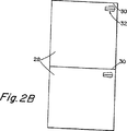
図2Bはまだ切断されていない材料のカードを搬送する連続的なウェブによる方法を示した平面図である。
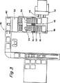
図3は本発明のカード処理装置の一実施形態の平面図である。
図4は本発明の他の実施形態の概略図である。
好ましい実施態様の詳細な記載
図1に、本発明のレーザー切断装置を全体として10で示す。材料としての堆積されたカード12は積重ね搬送装置14にフィードされる。この処理は、任意の物理的な面内で実行可能である。カードは、ウェブに対して右又は左に90°の角度をなして積重ねられるか、ウェブに対して並列に積重ねられることができる。これにより、カードのすべての縁部は選択的にさらされる。
積重ね搬送装置は、従来の技術から公知であり、オハイオ州、マニフォルドのマニフォルド インターナショナルから購入可能である。マニフォルド インターナショナルによって販売される積重ね搬送装置の一例は、Model 4026 TOTF(Turn Over Top Feeder)である。積重ね搬送装置14は、カードの表面の一部をさらすために、堆積部からの個々のカードを積重ねることができ、続いて、積重ねられたカードを他の堆積部16まで搬送することができる。
積重ねられたカード18が積重ね搬送装置14を通過する時に、個々のカードの表面にレーザービームを向けることが可能であり、その結果、カードから材料が局所的に発散される。レーザー装置20は、レーザービームを発生し、レーザービームをZ軸焦点合わせ部22まで供給することができる。レーザービームは、続いて、X及びY軸位置決めミラーを備えた二軸レーザーガルボ(two axis laser galvo)24を通過する。
図2Aは積重ねられたカード26の一部の平面図である。個々のカードは、積重ねられると表面28の一部をさらすことができる。各カードの先端30を検出してレーザー装置にトリガをかけるためにセンサが使用可能である。個々のカードは、レーザービームによって処理すべき領域にレーザービームが接触できるだけの領域のみさらされる必要があり、その領域を32で示す。
図2Bは材料のウェブの平面図である。領域32と接触すべくレーザー装置にトリガをかけるために各カードの先端30が使用可能である。幾つかの装置では、それぞれの材料の複製体の全表面28がさらされため、新しい材料片がスタートされる前に全表面が通過する必要がある。この場合、処理速度(つまり、分当たりのカード数)は同一になるが、処理時間は、レーザー及びガルボ装置が全経過時間中に各カードの先端30を追跡できる場合にのみ等しくなり、それゆえ、各カードの先端30と等しいかなり大きな視野が必要になる。
図3に、本発明のレーザー装置40の一実施形態の平面図を示す。図3の装置の材料カードは、様々な材料の多数層を有しており、それらが協働して各材料カードを形成している。各カードは、内側表面と印刷側とを有する。ウェブ材料は回転式ナイフ42に供給され、ナイフ42はウェブ材料を個々のカードに切断する。複数のカードは、続いて、スプリッタホイール44によって分離され、コンベヤ46に供給される。本実施形態では、カードはウェブに対して垂直に積重ねられる。カードは、停止プレート48に隣接し、更に、搬送すべき位置にカードを位置決めする調整プレート50を通過する。図面に示す実施形態では、カードの印刷側52は上側を向いている。レーザー装置54はシールド換気装置56の作動中にカードを処理する。続いてカードは、堆積され、更に、60のように印刷側を下側にすべくステーション58において回転される。
一方、図4では、積重ね搬送装置100はレーザー装置の下でカード102を搬送する。レーザー装置は、レーザー装置104と、(一の実施形態ではフィールドフラットニングレンズ108を他の実施形態ではz軸集束レンズ109を備えた)ガルボ106とを有する。タコメータ110は、処理装置が切断表面を追跡できるようにコントロール装置112に速度入力値を提供するのに使用される。コントロール装置112は、レーザー装置を始動し、更に、ガルボミラー106の位置及びz軸焦点合わせ補償の制御を行うことによって、所望のパターンを通じてレーザーをガイドする。先端トリガ120は、カードの先端を検出し、レーザー処理を開始するための信号を出す。コントロール装置112は、信号を受信すると、タコメータ110の信号に基づいて材料を追跡し、レーザー装置104及びビームの位置決め装置106を始動する。フィールドフラットニングレンズ(あるいは他の実施形態ではz軸集束レンズ)は、レーザービームがガルボミラーの全視野に及んで焦点を維持することができる手段を有する。
別個のシート材料は、積み込み位置から積重ね搬送装置に向かって真っ直ぐ前に、若しくは右又は左側に向けられて積重ねられる。ウェブ材料は、積み込み位置に到達する前に別個のシートに切断される。別個のシートは90°回転されて搬送される。この配列により、各シートの異なる縁部がレーザーに対してさらされる。
別個のシートは、シートの先端30が垂直方向に対して任意の角度に傾けられて、任意の角度でレーザー装置を通じて搬送される。シートの先端30が垂直方向に対して任意の角度に傾けられて配列されても、隣接するシートを積重ねる(重複させる)ことができ、シートの先端30を水平方向に沿ってシートを積重ねる場合と同様の効果が得られる。
実施例
本発明の顕著な一面を理解するために、本発明によって達成される効果の一例を以下に示す。
この仮定では以下のようにパラメータを設定する。
ウェブ速度 200m/分
印刷複製体 0.333m/部
スループット 600部/分
(200m/分÷0.333m/部)
総サイクル時間 100ミリ秒=0.001667分
切断時間 90ミリ秒=0.00150分
ガルボリセット時間 10ミリ秒=0.000167分
レーザー切断領域 0.033m幅(ウェブに対して横方向)×0.033m長さ(ウェブ方向)
ガルボ最大角度 ±15°
レーザー出力 200ワット
積重ね搬送速度
本実施例では、ウェブはブランクに切断され、ブランクは積重ね搬送装置まで搬送される。積重ねられたブランクは0.033mの露出領域を有する(90%は重複している)必要がある。最終的な積重ね搬送速度は1/10に減少される。
搬送速度
=(露出表面×分当たりの部数)
=(0.033mの露出表面/部)×(600部/分)
=20m/分(vs.200m/分のウェブ速度)
視野
ウェブ装置の切断時間を最大にするために、レーザー装置は切断時間中に部品を追跡する。
ウェブ追跡距離
=ウェブ速度×レーザー切断時間
=200m/分×0.0015分=0.3m
故に、ウェブ装置の視野は、作業領域が0.033mのみである場合に0.3m必要になる。
尚、積重ね装置において、レーザー装置は切断時間中に部品を追跡する。このことは数学的に示すことができる。
積重ね追跡距離
=搬送速度×レーザー切断時間
=20m/分×0.0015分=0.03m
積重ね装置の視野は0.033mまで減少される。
焦点距離
所定の視野の焦点距離は以下のように算出される。
焦点距離=視野÷2×Inv Tan 15°
ウェブ装置の焦点距離=0.562m
積重ね装置の焦点距離=0.056m
故に、積重ね装置における焦点距離は1/10に減少される。
スポット直径
スポット直径は以下の式に示すように焦点距離に正比例している。
スポット直径typ.=4L×f÷π×W(μm)
この関係式は、George Chryssolourisのテキスト“Basics of Laser Machining Theory and Practice”に詳細に示してある。ここで
波長L(μm)はCO2レーザーで10.6であり、
焦点距離f(mm)はウェブ装置で567、積重ね装置で56.7であり、
ビーム直径W(mm)はいずれの装置でも30である。
それぞれのスポット直径は以下の通りである。
ウェブ装置スポット直径=253μm
積重ね装置スポット直径=25μm
故に、積重ね装置は、焦点距離が短いために、小さいスポットを有する。焦点が合わされた全スポットの直径は1/10に減少される。
出力密度
積重ね装置の出力密度はウェブ装置の出力密度を越えて十分に増加される。
ウェブ装置出力密度=レーザー出力÷スポット領域
=0.40MW/cm2
積重ね装置出力密度=レーザー出力÷スポット領域
=40MW/cm2
積重ね装置出力密度は100倍に増加される。
実施例終わり
幾つかの実施形態と一の実施例を参照して本発明を説明したが、請求の範囲から逸脱することなく幾つかの変更及び修正を行うことができることが理解できる。TECHNICAL BACKGROUND AND DISCLOSURE OF THE INVENTION The present invention relates to an apparatus for use in laser processing of materials, in particular, to quickly cut a material in half, or to form a tear line in the material, or various other materials. The present invention relates to a method and an apparatus for performing laser processing.
Many processing devices known today feed and process a continuous web of uncut material. For example, in the packaging industry, a continuous web material is fed to a printing device and subsequently cut into individual packaging units for folding into a desired packaging form. Newspaper printing is another example, where the material (ie, paper) that has undergone the printing process is continuously fed and then cut into individual sections.
Of course, printing is not the only process incorporated into such devices, and paper is not the only material type that is continuously fed into such devices. In general, in the industry, a number of different processes are applied to a number of different materials in a continuous feed device.
Processing web material in a laser device requires power, tracking, and optical processing at the same speed as the web speed. The processing of conventional web devices as described in US Pat. No. 5,001,325 is fast, but requires a large field of view in the web direction for tracking, and therefore the focal length of the laser device is long. Due to the long focal length, the output of the laser device required for material processing increases.
The present invention provides a method and apparatus for stacking sheet material as it passes through an area to be processed by a laser device. The sheet source may be a sheet stack, a web sheet output device, or various other separate material feeds. By stacking sheet material, the velocity through the material laser device processing region, can be clearly smaller than the web speed itself, therefore, the laser device to reduce the field of view of Me line song optically tracked be able to. By increasing the rate at which overlapped, it is small camphor Rukoto the conveying speed. Furthermore, if the ratio of overlap length to the length of the web to be processed is very large (ie 100: 1), stacking can also increase the throughput per hour and the field of view is It is only necessary to cover%. On the other hand, when processing the web as it is with the same processing time, all lengths (100%) must be tracked. In other words, if the entire length is not tracked, the processing time is shortened (that is, if only 50% is tracked, the processing time is halved). Replacing this type of device can effectively affect the laser power, scan speed and power density on the workpiece surface. Therefore, this technique can effectively improve the effects of the laser device and the optical tracking device.
With the present invention, the output requirements of the laser device are reduced. In the present invention, a laser device can be used with low output requirements that cannot be achieved with conventional laser processing devices. A number of CO 2 laser devices can be used with prior art state-of-the-art galvo devices having limited power handling capabilities.
By carrying out the stacking, the conveying speed is considerably reduced. The speed of blanks stacked on the transport device (hereinafter referred to as “stack transport speed”) is reduced to 1/10 of the web speed when stacking is performed with 90% overlap. For example, if the web blanking speed is 200 meters / minute, using the stacking device performs stacking duplicate 90%, stacking transport speed becomes 20 m / min. In this example, the laser treatment to be performed is performed on a 10% exposed surface.
Since the speed on the stacking device is reduced to 20 m / min, the travel distance of what should be conveyed during the cutting cycle is 1/10. Therefore, the galvo tracking distance may be only 1/10 of the distance required in the web device. Thereby, the used focal distance can be shortened.
It is important to shorten the focal length because the focal length is directly proportional to the focused spot diameter. In this example, the galvo focal length is reduced by a factor of ten. By reducing the spot diameter in this way, the power density achieved is greatly affected. Since the power density is related to the size of the spot area, reducing the spot diameter increases the power density based on the square of the change in diameter. Therefore, the optical output requirements are also reduced. Furthermore, the optical path (ie, galvo, optical system, mirror) need only meet this slight power requirement.
The present invention can be used to create a tear or cut line at a predetermined location on a container to contribute to user friendliness in the container. Such containers are easily opened without tools such as scissors or knives.
These and other advantages will be apparent from the detailed description of the invention, the drawings and the claims that follow.
[Brief description of the drawings]
The various features and advantages of the present invention will be more readily understood by reference to the following detailed description, taken in conjunction with the accompanying drawings, in which: The same reference numbers indicate the same parts.
FIG. 1 is a schematic diagram of one embodiment of the present invention.
FIG. 2A is a plan view of a stack of deposited material cards of the present invention.
FIG. 2B is a plan view showing a continuous web method of conveying cards of material that has not yet been cut.
FIG. 3 is a plan view of an embodiment of the card processing apparatus of the present invention.
FIG. 4 is a schematic view of another embodiment of the present invention.
DETAILED DESCRIPTION OF THE PREFERRED EMBODIMENT In FIG. 1, a laser cutting device of the present invention is shown generally at 10. The deposited
Stack conveying devices are known from the prior art and can be purchased from Manifold International, Manifold, Ohio. An example of a stacked transport device sold by Manifold International is the Model 4026 TOTF (Turn Over Top Feeder). The
As the stacked
FIG. 2A is a plan view of a part of the stacked
FIG. 2B is a plan view of a web of material. The
In FIG. 3, the top view of one Embodiment of the laser apparatus 40 of this invention is shown. The material card of the device of FIG. 3 has multiple layers of various materials that cooperate to form each material card. Each card has an inner surface and a printing side. The web material is fed to a
On the other hand, in FIG. 4, the
The separate sheet material is stacked either straight forward from the loading position toward the stacking transport device, or directed to the right or left side. The web material is cut into separate sheets before reaching the loading position. Separate sheets are rotated 90 ° and conveyed. This arrangement exposes the different edges of each sheet to the laser.
The separate sheet is conveyed through the laser device at an arbitrary angle with the leading
EXAMPLES In order to understand a prominent aspect of the present invention, an example of the effect achieved by the present invention is shown below.
In this assumption, parameters are set as follows.
Web speed 200 m / min Print reproduction 0.333 m / part Throughput 600 parts / min (200 m / min ÷ 0.333 m / part)
Maximum galvo angle ± 15 °
Laser power 200 watts stack transport speed In this example, the web is cut into blanks and the blanks are transported to a stack transport apparatus. Stacked blanks should have an exposed area of 0.033m (90% overlap). The final stack transport speed is reduced to 1/10 .
Conveyance speed = (exposed surface x number of copies per minute)
= (0.033 m exposed surface / part) x (600 parts / min)
= 20 m / min (vs. web speed of 200 m / min)
In order to maximize the cutting time of the viewing web device, the laser device tracks the part during the cutting time.
Web tracking distance = web speed × laser cutting time = 200 m / min × 0.0015 min = 0.3 m
Therefore, the visual field of the web device is required to be 0.3 m when the working area is only 0.033 m.
In the stacking device, the laser device tracks the parts during the cutting time. This can be shown mathematically.
Stack tracking distance = conveying speed × laser cutting time = 20 m / min × 0.0015 min = 0.03 m
The field of view of the stacker is reduced to 0.033m.
Focal length The focal length of a predetermined field of view is calculated as follows.
Focal length = Field of view ÷ 2 x Inv Tan 15 °
Focal length of web device = 0.562m
Focal length of stacking device = 0.056m
Therefore, the focal length in the stacking device is reduced to 1/10 .
Spot diameter The spot diameter is directly proportional to the focal length as shown in the following equation.
Spot diameter typ. = 4L × f ÷ π × W (μm)
This relation is detailed in George Chryssolouris's text “Basics of Laser Machining Theory and Practice”. Here, the wavelength L (μm) is 10.6 with a CO 2 laser,
The focal length f (mm) is 567 for the web device and 56.7 for the stacking device,
The beam diameter W (mm) is 30 in any apparatus.
Each spot diameter is as follows.
Web device spot diameter = 253 μm
Stacker spot diameter = 25 μm
Hence, the stacking device has a small spot due to the short focal length. The diameter of all focused spots is reduced to 1/10 .
The power density of the power density stacker is sufficiently increased beyond the power density of the web device.
Web device output density = Laser output ÷ Spot area = 0.40 MW / cm 2
Stacking device power density = laser power / spot area = 40 MW / cm 2
The stacker power density is increased by a factor of 100.
Although the present invention has been described with reference to several embodiments and an example, it will be understood that a number of changes and modifications can be made without departing from the scope of the claims.
Claims (12)
レーザー装置の視野内の予め決定された通路に別個のシートをそれぞれ連続的に移動させて搬送する工程と、
一度に一のシートに対してレーザービームが向けられるように、前記レーザー装置からレーザービームを別個のシートに対して順次指向させる工程とを含む材料のレーザー処理方法。Stacking separate sheet materials on a conveying device such that a portion of one adjacent separate sheet material overlaps with each separate sheet material;
Each of the separate sheets is continuously moved to a predetermined path within the field of view of the laser device and conveyed, and
And sequentially directing the laser beam from the laser device to separate sheets so that the laser beam is directed to one sheet at a time.
ウェブを別個のシート材料に切断するために前記巻き付け装置に作用結合されている切断手段を設ける工程とを更に含む請求項1に記載の方法。Providing a web material winding device adjacent to the conveying device;
The method of claim 1, further comprising the step of providing cutting means operatively coupled to the wrapping device for cutting the web into separate sheet materials.
予め決定された通路内に積重ねられた別個のシートを搬送するためのコンベヤと、
積重ねられた別個のシートを処理するために前記コンベヤに対して位置決めされたレーザー装置とを具備しており、前記レーザー装置の焦点距離が、前記レーザー装置と、連続的な重複されていないシート材料に対して使用されるレーザー装置とが同一の材料スループットで処理を行いかつ同一のレーザー処理時間を条件とするときに、連続的な重複されていないシート材料に対して使用するのに必要なレーザー装置の焦点距離よりも少なくとも10%短くされている、別個のシート材料をレーザー処理するための処理装置。A stacking and conveying device for stacking separate sheet materials such that a portion of one adjacent separate sheet material and separate sheet material overlap each other;
A conveyor for conveying separate sheets stacked in a predetermined path;
A laser device positioned relative to the conveyor for processing the stacked separate sheets, the focal length of the laser device being continuous with the laser device and non- overlapping sheet material when the laser device used is that the same material subjected to throughput process and conditions the same laser treatment time for the laser needed to be used for the sheet material that are not contiguous overlapping A processing apparatus for laser processing a separate sheet material that is at least 10% shorter than the focal length of the apparatus.
レーザー装置の視野内の予め決定された通路に別個のシートをそれぞれ連続的に移動させて搬送する工程と、
一度に一のシートに対してレーザービームが向けられるように、前記レーザー装置からレーザービームを別個のシートに対して順次指向させる工程と、
予め切断されて堆積された別個のシート材料を前記搬送装置に隣接させて設ける工程と、
前記レーザー装置にトリガをかけるために別個のシートの先端を検出する検出装置を設ける工程とを含む材料のレーザー処理方法。Stacking separate sheet materials on a conveying device such that a portion of one adjacent separate sheet material overlaps with each separate sheet material;
Each of the separate sheets is continuously moved to a predetermined path within the field of view of the laser device and conveyed, and
Sequentially directing a laser beam from the laser device to separate sheets so that the laser beam is directed to one sheet at a time;
Providing a separate sheet material previously cut and deposited adjacent to the conveying device;
Providing a detection device for detecting a leading edge of a separate sheet for triggering the laser device.
Applications Claiming Priority (5)
| Application Number | Priority Date | Filing Date | Title |
|---|---|---|---|
| US48954795A | 1995-06-12 | 1995-06-12 | |
| US08/489,547 | 1995-06-12 | ||
| US08/541,047 US5688463A (en) | 1995-06-12 | 1995-10-11 | Laser processing of discrete sheets of material |
| US08/541,047 | 1995-10-11 | ||
| PCT/US1996/010138 WO1996041713A1 (en) | 1995-06-12 | 1996-06-11 | Laser processing of discrete sheets of material |
Publications (2)
| Publication Number | Publication Date |
|---|---|
| JPH11507608A JPH11507608A (en) | 1999-07-06 |
| JP4001244B2 true JP4001244B2 (en) | 2007-10-31 |
Family
ID=27049751
Family Applications (1)
| Application Number | Title | Priority Date | Filing Date |
|---|---|---|---|
| JP50328197A Expired - Lifetime JP4001244B2 (en) | 1995-06-12 | 1996-06-11 | Laser processing method for separate sheet material |
Country Status (12)
| Country | Link |
|---|---|
| US (3) | US5688463A (en) |
| EP (1) | EP0833740B1 (en) |
| JP (1) | JP4001244B2 (en) |
| AT (1) | ATE222171T1 (en) |
| AU (1) | AU699003B2 (en) |
| BR (1) | BR9608757A (en) |
| CA (1) | CA2224248C (en) |
| DE (1) | DE69623021T2 (en) |
| ES (1) | ES2181893T3 (en) |
| MX (1) | MX9710046A (en) |
| NZ (1) | NZ310853A (en) |
| WO (1) | WO1996041713A1 (en) |
Families Citing this family (33)
| Publication number | Priority date | Publication date | Assignee | Title |
|---|---|---|---|---|
| US5688463A (en) * | 1995-06-12 | 1997-11-18 | Combibloc, Inc. | Laser processing of discrete sheets of material |
| DE19520713C2 (en) * | 1995-06-12 | 1997-07-03 | Pkl Verpackungssysteme Gmbh | Method and device for producing perforations and / or half-cuts in printed multilayer composite material by means of laser beams |
| DE19537467C1 (en) * | 1995-10-07 | 1997-02-27 | Pkl Verpackungssysteme Gmbh | Cutting, perforating or inscribing repeatable patterns on moving composite material |
| AU6796398A (en) * | 1997-04-04 | 1998-10-30 | Sig Combibloc Inc. | Tear-away package opening |
| JP3691221B2 (en) * | 1997-09-24 | 2005-09-07 | 三菱電機株式会社 | Laser processing method |
| US6241646B1 (en) | 1998-02-09 | 2001-06-05 | Sig Combibloc Inc. | Tear-away container spout |
| US6098874A (en) * | 1998-02-09 | 2000-08-08 | Sig Combibloc Inc. | Tear-away container top |
| US6766941B1 (en) | 1998-02-09 | 2004-07-27 | Sig Combibloc, Inc. | Tear-away container top |
| GB9903570D0 (en) * | 1999-02-17 | 1999-04-07 | Mundet U K Limited | Packaging film |
| GB0014177D0 (en) * | 2000-06-09 | 2000-08-02 | Univ Warwick Science Park Limi | Packaging |
| DE50009122D1 (en) * | 2000-08-19 | 2005-02-03 | Carl Ingolf Lange | Processing device for flat bows |
| US6803538B2 (en) * | 2001-08-31 | 2004-10-12 | Honda Canada Inc. | Laser welding system |
| US9150342B2 (en) | 2003-04-16 | 2015-10-06 | Intercontinental Great Brands Llc | Resealable tray container |
| ES1061543Y (en) * | 2005-11-11 | 2006-06-16 | Rojas Jose Maria Pastrana | VERTICAL PACKAGING |
| US7531228B2 (en) * | 2005-11-23 | 2009-05-12 | Alcan Packaging Flexible France | Dual scored easy open film |
| US8308363B2 (en) | 2006-05-23 | 2012-11-13 | Kraft Foods Global Brands Llc | Package integrity indicator for container closure |
| US7963413B2 (en) | 2006-05-23 | 2011-06-21 | Kraft Foods Global Brands Llc | Tamper evident resealable closure |
| US7967510B2 (en) | 2006-08-08 | 2011-06-28 | Kellogg Company | Flexible container for pourable product |
| US8114451B2 (en) | 2006-12-27 | 2012-02-14 | Kraft Foods Global Brands Llc | Resealable closure with package integrity feature |
| US20080156863A1 (en) * | 2006-12-29 | 2008-07-03 | Weyerhaeuser Co. | Systems and methods for improving the readability of printed bar code symbols and the like |
| US8408792B2 (en) | 2007-03-30 | 2013-04-02 | Kraft Foods Global Brands Llc | Package integrity indicating closure |
| DE102008027130A1 (en) * | 2008-05-29 | 2009-12-10 | Fraunhofer-Gesellschaft zur Förderung der angewandten Forschung e.V. | Method for separating workpieces with a laser beam |
| US20100018974A1 (en) * | 2008-07-24 | 2010-01-28 | Deborah Lyzenga | Package integrity indicating closure |
| GB0819200D0 (en) | 2008-10-20 | 2008-11-26 | Cadbury Holdings Ltd | Packaging |
| US20110127319A1 (en) * | 2009-12-01 | 2011-06-02 | Kraft Foods Global Brands Llc | Resealable flexible film packaging products and methods of manufacture |
| DK2347971T3 (en) | 2010-01-26 | 2012-09-17 | Gen Biscuit | Re-sealable food packaging and manufacturing processes |
| US8814430B2 (en) * | 2010-02-23 | 2014-08-26 | Kraft Foods R&D, Inc. | Food package having opening feature |
| EP2368811B1 (en) | 2010-03-23 | 2012-08-22 | Generale Biscuit | Resealable packaging for food products and method of manufacturing |
| CN103003156B (en) | 2010-05-18 | 2015-09-16 | 洲际大品牌有限责任公司 | The flexible package of Reclosable and manufacture method thereof |
| US9656783B2 (en) | 2010-05-18 | 2017-05-23 | Intercontinental Great Brands Llc | Reclosable flexible packaging and methods for manufacturing same |
| EP3398862A1 (en) | 2011-03-17 | 2018-11-07 | Intercontinental Great Brands LLC | Reclosable flexible film packaging products and methods of manufacture |
| US10831865B2 (en) * | 2012-07-05 | 2020-11-10 | Koninklijke Philips N.V. | Medication management device and method |
| US20140336029A1 (en) * | 2013-05-07 | 2014-11-13 | The Procter & Gamble Company | Process for laser puncturing holes into water-soluble films |
Family Cites Families (26)
| Publication number | Priority date | Publication date | Assignee | Title |
|---|---|---|---|---|
| US2776831A (en) * | 1953-01-09 | 1957-01-08 | S & S Corrugated Paper Mach | Sheet inverting mechanism |
| US3270630A (en) * | 1963-08-21 | 1966-09-06 | Bostitch Inc | Material handling apparatus |
| US3790744A (en) * | 1971-07-19 | 1974-02-05 | American Can Co | Method of forming a line of weakness in a multilayer laminate |
| CH586115A5 (en) * | 1975-09-09 | 1977-03-31 | Grapha Holding Ag | |
| DE2725547C2 (en) * | 1977-06-07 | 1983-12-22 | De La Rue Giori S.A., 1003 Lausanne | Method and device for the fan-like pushing of bow-shaped or booklet-shaped objects |
| DE2939277A1 (en) * | 1979-09-28 | 1981-04-09 | E.C.H. Will (Gmbh & Co), 2000 Hamburg | METHOD AND DEVICE FOR BRAKING AND OVERLAPPING PAPER SHEETS |
| US4279183A (en) * | 1979-10-26 | 1981-07-21 | Custom Packaging Systems | Rotary heat cutter for plastic webs |
| US4341480A (en) * | 1979-12-26 | 1982-07-27 | General Electric Company | Feed mechanism for continuous and cut form paper |
| US4440051A (en) * | 1981-07-30 | 1984-04-03 | E.C.H. Will (Gmbh & Co.) | Apparatus for cutting and transporting sheets of paper or the like |
| JP2565860B2 (en) * | 1983-04-02 | 1996-12-18 | エー・ツエー・ハー・ウイル・ゲゼルシヤフト・ミト・ベシユレンクテル・ハフツング | Method and apparatus for braking and stacking paper sheets in a paper machine |
| US4601394A (en) * | 1984-05-07 | 1986-07-22 | Xerox Corporation | Zip code sorter for article labeling system |
| GB8415046D0 (en) * | 1984-06-13 | 1984-07-18 | Amalgamated Mining Trading | Forming containers |
| FR2576836B1 (en) * | 1985-02-05 | 1989-10-27 | Dupuy Eng Sa | METHOD AND DEVICE FOR LASER GROOVING OF PLASTIC SHEETS |
| US4762514A (en) * | 1985-11-01 | 1988-08-09 | Fujimori Kogyo Co., Ltd. | Method of making beverage packaging bag |
| US4680442A (en) * | 1986-04-04 | 1987-07-14 | Laser Machining, Inc. | Apparatus for cutting multiple layers of fabric |
| US4945203A (en) * | 1986-11-06 | 1990-07-31 | American Fluoroseal Corporation | Method and apparatus for making fluorocarbon film plastic bags using a laser |
| US4805890A (en) * | 1987-08-06 | 1989-02-21 | Merrill David Martin | Sheet stacking machine |
| US4873415A (en) * | 1988-02-02 | 1989-10-10 | Raycon Corporation | Method for welding galvanized material |
| EP0353527A3 (en) * | 1988-08-01 | 1990-09-05 | Oscar Roth | Device for unpiling a pallet loaded with a stack of paper sheets |
| ATE102119T1 (en) * | 1988-09-07 | 1994-03-15 | Leeuwarder Papier | METHOD OF MAKING SCORES IN PACKAGING MATERIAL. |
| US5197364A (en) * | 1990-04-02 | 1993-03-30 | Grapha-Holding Ag | Method of and apparatus for trimming lateral marginal portions of sheets in a stream of partly overlapping sheets |
| US5165314A (en) * | 1990-07-24 | 1992-11-24 | Marquip, Inc. | Slitting shingled sheets |
| US5229180A (en) * | 1991-10-02 | 1993-07-20 | American National Can Company | Laser scored package |
| US5389761A (en) * | 1993-09-17 | 1995-02-14 | General Motors Corporation | Method and apparatus for cleaning metal pieces prior to resistive seam welding or laser lap seam welding |
| DE4411597B4 (en) * | 1994-04-02 | 2005-09-22 | Kugler-Womako Gmbh | sheet feeder |
| US5688463A (en) * | 1995-06-12 | 1997-11-18 | Combibloc, Inc. | Laser processing of discrete sheets of material |
-
1995
- 1995-10-11 US US08/541,047 patent/US5688463A/en not_active Expired - Fee Related
-
1996
- 1996-06-11 JP JP50328197A patent/JP4001244B2/en not_active Expired - Lifetime
- 1996-06-11 MX MX9710046A patent/MX9710046A/en unknown
- 1996-06-11 ES ES96919375T patent/ES2181893T3/en not_active Expired - Lifetime
- 1996-06-11 CA CA002224248A patent/CA2224248C/en not_active Expired - Lifetime
- 1996-06-11 BR BR9608757A patent/BR9608757A/en not_active IP Right Cessation
- 1996-06-11 AT AT96919375T patent/ATE222171T1/en active
- 1996-06-11 AU AU61729/96A patent/AU699003B2/en not_active Expired
- 1996-06-11 DE DE69623021T patent/DE69623021T2/en not_active Expired - Lifetime
- 1996-06-11 WO PCT/US1996/010138 patent/WO1996041713A1/en active IP Right Grant
- 1996-06-11 EP EP96919375A patent/EP0833740B1/en not_active Expired - Lifetime
- 1996-06-11 NZ NZ310853A patent/NZ310853A/en not_active IP Right Cessation
-
1997
- 1997-07-29 US US08/902,237 patent/US5843364A/en not_active Expired - Lifetime
-
1998
- 1998-07-31 US US09/126,820 patent/US6028289A/en not_active Expired - Lifetime
Also Published As
| Publication number | Publication date |
|---|---|
| JPH11507608A (en) | 1999-07-06 |
| DE69623021D1 (en) | 2002-09-19 |
| EP0833740A4 (en) | 1998-12-23 |
| ATE222171T1 (en) | 2002-08-15 |
| US6028289A (en) | 2000-02-22 |
| US5688463A (en) | 1997-11-18 |
| US5843364A (en) | 1998-12-01 |
| CA2224248A1 (en) | 1996-12-27 |
| CA2224248C (en) | 2001-01-30 |
| AU6172996A (en) | 1997-01-09 |
| ES2181893T3 (en) | 2003-03-01 |
| AU699003B2 (en) | 1998-11-19 |
| DE69623021T2 (en) | 2003-04-03 |
| MX9710046A (en) | 1998-04-30 |
| WO1996041713A1 (en) | 1996-12-27 |
| NZ310853A (en) | 1998-11-25 |
| EP0833740A1 (en) | 1998-04-08 |
| BR9608757A (en) | 1999-07-06 |
| EP0833740B1 (en) | 2002-08-14 |
Similar Documents
| Publication | Publication Date | Title |
|---|---|---|
| JP4001244B2 (en) | Laser processing method for separate sheet material | |
| MXPA97010046A (en) | Processing with material leaf laser leaf | |
| US10525653B2 (en) | Plant and method for producing corrugated cardboard with gluing defect detector | |
| US20130017940A1 (en) | Machines and methods for producing packaging boxes | |
| JPH0815965B2 (en) | Apparatus and method for cutting continuous moving webs | |
| WO2004108428A2 (en) | Bundled printed sheets | |
| US10016908B2 (en) | Liquid nitrogen jet stream processing of substrates | |
| US6783622B1 (en) | Method and arrangement for producing webs of material that have discrete pieces of material mounted thereon | |
| US20100236997A1 (en) | Profile based laser cutting within a high-speed transport device | |
| JPH0412834A (en) | Processing method for adhesive sheet | |
| JP2003340780A (en) | Method and apparatus for machining web | |
| JP4619865B2 (en) | Sheet length measuring device, sheet sorting line, sheet cutting line, and sheet length measuring method | |
| JP2018069615A (en) | Laminator and method for laminating | |
| TW201341099A (en) | Laser light irradiation system, laser light irradiation method and recording medium | |
| JPH09192863A (en) | Pattern cutting method for article | |
| JPH0994685A (en) | Cutting device for continuous paper | |
| JPS5978067A (en) | Device for providing perforation for form | |
| KR102269052B1 (en) | Laser cutting system | |
| KR102667004B1 (en) | System for producing electrodes of battery | |
| US20240157480A1 (en) | Method for processing a cardboard with a laser beam | |
| JP2004262512A (en) | Method for printing label | |
| JPH0818271B2 (en) | Sheet bundle cutting method and device | |
| JPS606290A (en) | Laser cutter | |
| JP2004020601A (en) | Apparatus and method for processing photosensitive material | |
| JP2002067188A (en) | Soft packaging material processing apparatus, perforation part forming processing apparatus to soft packaging material, and package |
Legal Events
| Date | Code | Title | Description |
|---|---|---|---|
| A131 | Notification of reasons for refusal |
Free format text: JAPANESE INTERMEDIATE CODE: A131 Effective date: 20060328 |
|
| A521 | Request for written amendment filed |
Free format text: JAPANESE INTERMEDIATE CODE: A523 Effective date: 20060628 |
|
| A524 | Written submission of copy of amendment under article 19 pct |
Free format text: JAPANESE INTERMEDIATE CODE: A524 Effective date: 20060628 |
|
| TRDD | Decision of grant or rejection written | ||
| A01 | Written decision to grant a patent or to grant a registration (utility model) |
Free format text: JAPANESE INTERMEDIATE CODE: A01 Effective date: 20070710 |
|
| A61 | First payment of annual fees (during grant procedure) |
Free format text: JAPANESE INTERMEDIATE CODE: A61 Effective date: 20070809 |
|
| FPAY | Renewal fee payment (event date is renewal date of database) |
Free format text: PAYMENT UNTIL: 20100824 Year of fee payment: 3 |
|
| R150 | Certificate of patent or registration of utility model |
Free format text: JAPANESE INTERMEDIATE CODE: R150 |
|
| FPAY | Renewal fee payment (event date is renewal date of database) |
Free format text: PAYMENT UNTIL: 20100824 Year of fee payment: 3 |
|
| FPAY | Renewal fee payment (event date is renewal date of database) |
Free format text: PAYMENT UNTIL: 20110824 Year of fee payment: 4 |
|
| FPAY | Renewal fee payment (event date is renewal date of database) |
Free format text: PAYMENT UNTIL: 20120824 Year of fee payment: 5 |
|
| FPAY | Renewal fee payment (event date is renewal date of database) |
Free format text: PAYMENT UNTIL: 20130824 Year of fee payment: 6 |
|
| R250 | Receipt of annual fees |
Free format text: JAPANESE INTERMEDIATE CODE: R250 |
|
| R250 | Receipt of annual fees |
Free format text: JAPANESE INTERMEDIATE CODE: R250 |
|
| R250 | Receipt of annual fees |
Free format text: JAPANESE INTERMEDIATE CODE: R250 |
|
| EXPY | Cancellation because of completion of term |