JP4000454B2 - Receiving apparatus and receiving method - Google Patents
Receiving apparatus and receiving method Download PDFInfo
- Publication number
- JP4000454B2 JP4000454B2 JP2002136609A JP2002136609A JP4000454B2 JP 4000454 B2 JP4000454 B2 JP 4000454B2 JP 2002136609 A JP2002136609 A JP 2002136609A JP 2002136609 A JP2002136609 A JP 2002136609A JP 4000454 B2 JP4000454 B2 JP 4000454B2
- Authority
- JP
- Japan
- Prior art keywords
- transponder
- circuit
- data
- image
- predictor
- Prior art date
- Legal status (The legal status is an assumption and is not a legal conclusion. Google has not performed a legal analysis and makes no representation as to the accuracy of the status listed.)
- Expired - Fee Related
Links
Images


Classifications
-
- H—ELECTRICITY
- H04—ELECTRIC COMMUNICATION TECHNIQUE
- H04N—PICTORIAL COMMUNICATION, e.g. TELEVISION
- H04N21/00—Selective content distribution, e.g. interactive television or video on demand [VOD]
- H04N21/40—Client devices specifically adapted for the reception of or interaction with content, e.g. set-top-box [STB]; Operations thereof
- H04N21/47—End-user applications
-
- H—ELECTRICITY
- H04—ELECTRIC COMMUNICATION TECHNIQUE
- H04N—PICTORIAL COMMUNICATION, e.g. TELEVISION
- H04N21/00—Selective content distribution, e.g. interactive television or video on demand [VOD]
- H04N21/40—Client devices specifically adapted for the reception of or interaction with content, e.g. set-top-box [STB]; Operations thereof
- H04N21/43—Processing of content or additional data, e.g. demultiplexing additional data from a digital video stream; Elementary client operations, e.g. monitoring of home network or synchronising decoder's clock; Client middleware
- H04N21/433—Content storage operation, e.g. storage operation in response to a pause request, caching operations
-
- H—ELECTRICITY
- H04—ELECTRIC COMMUNICATION TECHNIQUE
- H04N—PICTORIAL COMMUNICATION, e.g. TELEVISION
- H04N21/00—Selective content distribution, e.g. interactive television or video on demand [VOD]
- H04N21/40—Client devices specifically adapted for the reception of or interaction with content, e.g. set-top-box [STB]; Operations thereof
- H04N21/41—Structure of client; Structure of client peripherals
- H04N21/426—Internal components of the client ; Characteristics thereof
- H04N21/42607—Internal components of the client ; Characteristics thereof for processing the incoming bitstream
- H04N21/4263—Internal components of the client ; Characteristics thereof for processing the incoming bitstream involving specific tuning arrangements, e.g. two tuners
-
- H—ELECTRICITY
- H04—ELECTRIC COMMUNICATION TECHNIQUE
- H04N—PICTORIAL COMMUNICATION, e.g. TELEVISION
- H04N21/00—Selective content distribution, e.g. interactive television or video on demand [VOD]
- H04N21/40—Client devices specifically adapted for the reception of or interaction with content, e.g. set-top-box [STB]; Operations thereof
- H04N21/43—Processing of content or additional data, e.g. demultiplexing additional data from a digital video stream; Elementary client operations, e.g. monitoring of home network or synchronising decoder's clock; Client middleware
- H04N21/431—Generation of visual interfaces for content selection or interaction; Content or additional data rendering
- H04N21/4312—Generation of visual interfaces for content selection or interaction; Content or additional data rendering involving specific graphical features, e.g. screen layout, special fonts or colors, blinking icons, highlights or animations
- H04N21/4316—Generation of visual interfaces for content selection or interaction; Content or additional data rendering involving specific graphical features, e.g. screen layout, special fonts or colors, blinking icons, highlights or animations for displaying supplemental content in a region of the screen, e.g. an advertisement in a separate window
-
- H—ELECTRICITY
- H04—ELECTRIC COMMUNICATION TECHNIQUE
- H04N—PICTORIAL COMMUNICATION, e.g. TELEVISION
- H04N21/00—Selective content distribution, e.g. interactive television or video on demand [VOD]
- H04N21/40—Client devices specifically adapted for the reception of or interaction with content, e.g. set-top-box [STB]; Operations thereof
- H04N21/43—Processing of content or additional data, e.g. demultiplexing additional data from a digital video stream; Elementary client operations, e.g. monitoring of home network or synchronising decoder's clock; Client middleware
- H04N21/44—Processing of video elementary streams, e.g. splicing a video clip retrieved from local storage with an incoming video stream, rendering scenes according to MPEG-4 scene graphs
- H04N21/4402—Processing of video elementary streams, e.g. splicing a video clip retrieved from local storage with an incoming video stream, rendering scenes according to MPEG-4 scene graphs involving reformatting operations of video signals for household redistribution, storage or real-time display
- H04N21/440263—Processing of video elementary streams, e.g. splicing a video clip retrieved from local storage with an incoming video stream, rendering scenes according to MPEG-4 scene graphs involving reformatting operations of video signals for household redistribution, storage or real-time display by altering the spatial resolution, e.g. for displaying on a connected PDA
-
- H—ELECTRICITY
- H04—ELECTRIC COMMUNICATION TECHNIQUE
- H04N—PICTORIAL COMMUNICATION, e.g. TELEVISION
- H04N21/00—Selective content distribution, e.g. interactive television or video on demand [VOD]
- H04N21/40—Client devices specifically adapted for the reception of or interaction with content, e.g. set-top-box [STB]; Operations thereof
- H04N21/47—End-user applications
- H04N21/475—End-user interface for inputting end-user data, e.g. personal identification number [PIN], preference data
- H04N21/4755—End-user interface for inputting end-user data, e.g. personal identification number [PIN], preference data for defining user preferences, e.g. favourite actors or genre
-
- H—ELECTRICITY
- H04—ELECTRIC COMMUNICATION TECHNIQUE
- H04N—PICTORIAL COMMUNICATION, e.g. TELEVISION
- H04N21/00—Selective content distribution, e.g. interactive television or video on demand [VOD]
- H04N21/40—Client devices specifically adapted for the reception of or interaction with content, e.g. set-top-box [STB]; Operations thereof
- H04N21/47—End-user applications
- H04N21/482—End-user interface for program selection
-
- H—ELECTRICITY
- H04—ELECTRIC COMMUNICATION TECHNIQUE
- H04N—PICTORIAL COMMUNICATION, e.g. TELEVISION
- H04N21/00—Selective content distribution, e.g. interactive television or video on demand [VOD]
- H04N21/40—Client devices specifically adapted for the reception of or interaction with content, e.g. set-top-box [STB]; Operations thereof
- H04N21/41—Structure of client; Structure of client peripherals
- H04N21/426—Internal components of the client ; Characteristics thereof
Description
【0001】
【発明の属する技術分野】
この発明は、デジタル衛星放送やデジタル地上波放送などのデジタルテレビ放送の受信装置に関する。
【0002】
【従来の技術】
デジタルテレビ放送においては、図6に示すように、そのデジタルテレビ放送のための周波数帯が、複数のトランスポンダと呼ばれる帯域に分割され、そのトランスポンダのそれぞれにおいて、複数のテレビ番組、動画、音声、各種のデータなど、多種多様なデジタル情報が多重化されて放送されている。
【0003】
そして、デジタルテレビ放送においては、1つのトランスポンダで複数のチャンネル(テレビ番組)が放送されるので、あるチャンネルの画面の中に、同じトランスポンダ内の別のチャンネルの縮小画面を表示する、いわゆるピクチャインピクチャを行うこともできる。あるいは、受信装置にHDDなどのデジタル記録装置を用意すれば、あるチャンネルのテレビ番組を見ながら、同じトランスポンダ内の別のチャンネルのテレビ番組を録画することもできる。
【0004】
また、1つのトランスポンダにより標準方式で番組を放送する場合には、最大で6チャンネル(サービス)まで放送でき、高品位方式で番組を放送する場合には、最大で2チャンネルまで放送できる。このため、トランスポンダがテレビ番組を放送する場合には、同時にEPG(電子番組表)のデータも放送される。そして、デジタルテレビ放送の受信装置においては、放送されてきたEPGのデータを使って番組表を表示するとともに、その番組表から希望する番組を選択できるようにされている。
【0005】
したがって、デジタルテレビ放送およびその受信装置によれば、アナログテレビ放送と比べ、視聴者(ユーザ)は多数のチャンネルを楽しむことができる。
【0006】
【発明が解決しようとする課題】
ところで、EPGのデータを使って番組表を表示すると、例えば図7Aのように、横軸が時刻で、縦軸がチャンネルの番組表が表示される。そして、視聴者が時刻方向のスクロールを指示すると、この番組表は横方向にスクロールされ、図に表示されていない時刻についても番組を知ることができ、チャンネル方向のスクロールを指示すると、この番組表は縦方向にスクロールされ、図に表示されていないチャンネルについても番組を知ることができる。
【0007】
ところが、図6にも示すように、あるトランスポンダnでテレビ番組を放送している場合、そのトランスポンダnで放送しているEPGは、そのトランスポンダnで放送している番組については、詳細な情報を有するが、他のトランスポンダで放送してい番組については、簡単な情報を有するだけである。
【0008】
このため、受信装置があるトランスポンダnを受信している場合に番組表を表示させると、例えば図7Aに示すように、そのトランスポンダnについては、チャンネルごとに、番組名と放送時刻とが詳細に表示されるが、隣のトランスポンダ(n+1)については、現在放送中の番組の番組名が表示される程度であり、その番組に続いて放送される番組については、何も表示されない。
【0009】
そして、受信しているトランスポンダを、トランスポンダnからトランスポンダ(n+1)に切り換えると、図7Bに示すように、そのトランスポンダ(n+1)については、チャンネルごとに、番組名と放送時刻とが詳細に表示される。なお、このとき、さらに隣りのトランスポンダ(n+2)については、やはり現在放送中の番組の番組名が表示される程度であり、その番組に続いて放送される番組については、何も表示されない。
【0010】
そして、受信するトランスポンダの切り換えをフロントエンド回路に指示してから、実際にトランスポンダが切り換わり、その後、EGPのデータが安定に得られるようになるまでには、1秒弱の時間を必要とする。
【0011】
このため、番組表をスクロール表示させる場合、そのスクロールがトランスポンダをまたぐとき、スクロールが一時的に停止することになるので、スクロールがぎくしゃくしてしまい、視聴者にストレスを与えたり、操作性が悪いと感じさせたりしてしまう。
【0012】
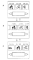
また、例えば図8に示すように、ピクチャインピクチャの機能を利用することにより3つの連続するチャンネルの縮小画面を、動画の状態で同時に表示するとともに、視聴者の指示にしたがってその縮小画面となるチャンネルを順に切り換えていけば(以下、このような表示を「チャンネルスクロール表示」と呼ぶ)、視聴者は番組内容を実際に見ながらチャンネルを選択することができるが、このチャンネルスクロール表示の場合も、表示されるチャンネルがトランスポンダをまたぐときに、チャンネルの切り換えが一時的に停止するので、やはり視聴者に操作性が悪いと感じさせたり、ストレスを与えたりしてしまう。
【0013】
この発明は、以上のような点にかんがみ、番組表をチャンネル方向にスクロール表示させたり、チャンネルスクロール表示を行ったりするときに、表示内容がトランスポンダをまたぐようになっても、そのスクロールが停止しないようにするものである。
【0014】
【課題を解決するための手段】
この発明においては、
デジタルテレビ放送のトランスポンダを受信する第1および第2のフロントエンド回路と、
これら第1および第2のフロントエンド回路の受信した上記トランスポンダに含まれるデータを蓄積するメモリ回路と、
このメモリ回路に蓄積された上記データにしたがって所定の画像として表示される画像信号を形成する回路と、
上記第1および第2のフロントエンド回路の受信するトランスポンダを制御する制御回路と
を有し、
この制御回路は、上記トランスポンダごとにセットあるいはリセットされる予測子を有し、
上記制御回路の制御は、
上記トランスポンダを周波数が高い方向の次のトランスポンダに変更するスクロール操作が行われたときには、上記予測子のうち、上記画像の表示に使用されているトランスポンダの次のトランスポンダの予測子をセットするとともに、他の予測子をリセットし、
上記トランスポンダを周波数が低い方向の前のトランスポンダに変更するスクロール操作が行われたときには、上記予測子のうち、上記画像の表示に使用されているトランスポンダの前のトランスポンダの予測子をセットするとともに、他の予測子をリセットし、
上記第1のフロントエンド回路により受信されて上記メモリ回路に蓄積されたトランスポンダのデータを使用して所定の画像を表示している期間には、上記第2のフロントエンド回路が、上記セットされている予測子のトランスポンダを受信して上記画像の表示に次に必要になるであろうデータを上記メモリ回路に蓄積し、
上記第2のフロントエンド回路により受信されて上記メモリ回路に蓄積されたトランスポンダのデータを使用して所定の画像を表示している期間には、上記第1のフロントエンド回路が、上記セットされている予測子のトランスポンダを受信して上記画像の表示に次に必要になるであろうデータを上記メモリ回路に蓄積する制御である
ようにした受信装置
とするものである。
【0015】
【発明の実施の形態】
図1は、この発明による受信装置をセットトップボックス形式に構成した場合の一形態を示す。すなわち、アンテナ10によりデジタルテレビ放送が受信されるとともに、中間周波信号にダウンコンバートされ、この中間周波信号が受信装置20の第1および第2のフロントエンド回路(チューナ回路)21、22に供給される。このフロントエンド回路21、22においては、これに供給された中間周波信号に局部発振信号が乗算されて中間周波信号はベースバンド信号に変換される。さらに、フロントエンド回路21、22において、ベースバンド信号を同期引き込みして復調および誤り訂正などの処理が行われ、フロントエンド回路21、22からはトランスポートストリームが出力される。
【0016】
そして、このトランスポートストリームが、188バイトの固定長を基本単位としてデマックス回路23に供給され、パケットIDにしたがって画像データ、音声データ、データ放送用データ、およびそれらに付随する各種の情報データに分類され、この分類されたデータが一時記憶用の記憶回路、例えばメモリ回路24にいったん格納される。なお、デマックス回路23には、番組の蓄積用のデバイスとして例えばHDD25が接続され、視聴者の操作にしたがって後述するように制御される。また、メモリ回路24に蓄積されたデータは、新しいデータが受信されたときには、更新されていく。
【0017】
そして、メモリ回路24に格納されたデータのうち、画像データおよび音声データが、デマックス回路23を通じてMPEGデコーダ回路26に供給されてもとのデジタル画像データおよびデジタル音声データに復号処理され、そのデジタル画像データがOSD回路27に供給される。この場合、MPEGデコーダ回路26は、縮小画面用として動画の画像データを3チャンネル分まで同時にデコードできるものとする。また、OSD回路27は、後述するシステム制御回路31により制御され、各種の文字やグラフィックッスを表示するためのデジタル画像データ、例えば番組表として表示されるデジタル画像データを形成し、この画像データをMPEGデコーダ回路26からのデジタル画像データに合成するためのものである。
【0018】
そして、OSD回路27からのデジタル画像データが例えばNTSCエンコーダ回路28に供給されてNTSC方式のデジタル映像信号にエンコードされ、このデジタル映像信号と、MPEGデコーダ回路26からのデジタル音声データとがD/Aコンバータ回路29V、29Sに供給されてアナログの映像信号および音声信号にD/A変換され、これら信号が例えばテレビ受像機40に供給されて画像および音声として出力される。
【0019】
また、メモリ回路24に格納されたデータのうち、データ放送用データおよび付随する情報データが、システム制御回路31により解析されてデータ放送用のテキストとして使用され、あるいはデマックス回路23におけるパケット分離の情報として使用される。
【0020】
そして、システム制御回路31はマイクロコンピュータなどにより構成されるとともに、そのマイクロコンピュータにはリアルタイムOSが搭載される。そして、このシステム制御回路31によりOSD回路27が制御されて上述のように表示用の画像データの形成および合成が行われる。なお、テレビ受像機40に番組表として表示される画像データは、このOSD回路27において、受信したEPGのデータに基づいて形成される。
【0021】
また、視聴者がリモコン(遠隔操作)の送信機50を操作したとき、その送信機50から出力されるリモコン信号、例えば赤外線光がフォトセンサ32により受光され、その出力信号が受信回路33により処理されてからシステム制御回路31に供給される。すると、システム制御回路31を構成するマイクロコンピュータには割り込みがかかり、その送信機50の操作に対応した処理が実行される。
【0022】
そして、フロントエンド回路21、22、デマックス回路23およびHDD25が、システム制御回路31により制御され、この制御により、フロントエンド回路21、22の受信するトランスポンダの切り換え、およびメモリ24からMPEGデコーダ回路26に供給される画像データおよび音声データの選択が行われる。
【0023】
また、HDD25の書き込みおよび読み出しも、システム制御回路31により制御され、フロントエンド回路21、22が受信しているトランスポンダのうちの所定のチャンネルの画像データおよび音声データがHDD25に書き込まれ、あるいはHDD25に書き込まれた画像データおよび音声データが読み出されるとともに、MPEGデコーダ回路26に供給される。
【0024】
したがって、フロントエンド回路21、22により、それぞれ任意のトランスポンダの任意の番組を受信でき、その番組をテレビ受像機40により視聴することができる。また、そのとき、任意の番組について、ピクチャインピクチャを行うこともできる。さらに、視聴中の番組や裏番組をHDD25に録画し、その録画した番組を視聴することもできる。
【0025】
そして、特にこの発明においては、システム制御回路31を構成するマイクロコンピュータに、これが実行するソフトウェアの一部として、例えば図2に示すルーチン100が用意される。このルーチン100は、図2においては、この発明に関係する部分だけを抜粋して示しているが、番組表の表示(およびチャンネルスクロール表示)を制御するためのものである。
【0026】
すなわち、このルーチン100は、フロントエンド回路21、22の受信するトランスポンダを交互に切り換えることにより、例えば図3に示すように、表示された番組表をチャンネル方向(縦軸の方向)にスクロールさせる場合、番組表がトランスポンダをまたぐときでも、表示が一時的に停止することがなく、滑らかにスクロールされていくようにするものである。
【0027】
ここで、視聴者がトランスポンダnで放送されているチャンネルの番組を見ているものとする。そして、このとき、トランスポンダnはフロントエンド回路21が受信しているとともに、フロントエンド回路22は次のトランスポンダ(n+1)を受信しているものとする。なお、トランスポンダn、(n+1)が受信されているので、このとき、メモリ回路24には、トランスポンダn、(n+1)で放送されているチャンネルについてのEPGのデータが蓄積されていることになる。
【0028】
そして、このような状態にあるとき、視聴者がリモコンの送信機50により番組表の表示を指示すると、システム制御回路31において、ルーチン100の処理がステップ101からスタートし、次にステップ102において、OSD回路27によりメモリ回路24に格納されているEPGのデータを使用して現在受信中のトランスポンダn、(n+1)の番組表の画像データが形成され、この画像データがNTSCエンコーダ回路28に供給される。
【0029】
したがって、テレビ受像機40には、例えば図3Aに示すように、現在受信中のトランスポンダnに含まれる第123チャンネル〜第129チャンネルの番組表が表示されるとともに、次のトランスポンダ(n+1)に含まれる第129チャンネルの番組表も一体に続いて表示される。また、図示はしないが、この番組表のうち、それまで受信していたチャンネルの行には、カーソルが表示される。
【0030】
続いて、処理はステップ111に進み、このステップ111において、リモコンの送信機50の操作キーの入力待ちとなり、操作キーが押されると、処理はステップ112に進み、このステップ112において、ステップ111で入力されたキーがチャンネル方向のスクロールキーであるかどうかが判別され、チャンネル方向のスクロールキーのときには、処理はステップ112からステップ113に進み、トランスポンダの予測子が立てられる。
【0031】
この予測子は、トランスポンダごとに用意されるものであり、ステップ111により押されたスクロールキーがチャンネル数字を大きくする方向のキーのときには(番組表に表示されているカーソルを図3Aにおける下方向に移動させるためのキー操作のときには)、トランスポンダ(n+1)の予測子が“1”にセットされ、他のトランスポンダの予測子は“0”にリセットされる。逆に、ステップ111により押されたスクロールキーがチャンネル数字を小さくする方向のキーのときには(番組表に表示されているカーソルを図3Aにおける上方向に移動させるためのキー操作のときには)、トランスポンダ(n−1)の予測子が“1”にセットされ、他のトランスポンダの予測子は“0”にリセットされる。
【0032】
つまり、ステップ111により押されたスクロールキーがチャンネル数字を大きくする方向のキーのときには、そのときまで番組の表示に使用されていたトランスポンダ(今の場合はトランスポンダn)の次のトランスポンダ(今の場合トランスポンダ(n+1))の予測子が“1”にセットされ、他のトランスポンダの予測子は“0”にリセットされ、逆に、ステップ111により押されたスクロールキーがチャンネル数字を小さくする方向のキーのときには、そのときまで番組に使用されていたトランスポンダの前のトランスポンダ(今の場合トランスポンダ(n−1))の予測子が“1”にセットされ、他のトランスポンダの予測子は“0”にリセットされる。
【0033】
続いて処理はステップ114に進み、このステップ114において、ステップ113によりセットされた予測子に対応するトランスポンダのEPGのデータが受信済みであって、メモリ回路24に蓄積されているかどうかが判別される。今の場合、該当するトランスポンダはトランスポンダ(n+1)であり、そのEPGのデータはメモリ回路24に蓄積されているので、処理はステップ114からステップ121に進み、このステップ121において、番組表に表示されているカーソルが1チャンネル分だけチャンネル方向に移動させられ、あるいはカーソルが番組表の最下行または最上行に表示されているときには、番組表がチャンネル数字が大きくなる方向または小さくなる方向に1チャンネル分だけスクロールされる。図2Bは、番組表がチャンネル数字が大きくなる方向に1チャンネル分だけスクロールされた場合である。
【0034】
そして、処理はステップ121に続いてステップ122に進み、このステップ122において、フロントエンド回路21、22のうち、トランスポンダを受信する必要のないフロントエンド回路が待機中(フロントエンド回路の出力を有効に使用しない状態)とされ、その後、ステップ111に戻る。
【0035】
したがって、リモコンの送信機50のチャンネル方向のスクロールキーを押すと、メモリ回路24に番組表の表示に必要なデータが蓄積されているトランスポンダのチャンネルについては、チャンネル方向のスクロールキーの操作に対応して、カーソルが移動し、さらに番組表はチャンネル数字が大きくなる方向に、あるいは小さくなる方向にスクロールされていく。
【0036】
一方、ステップ114において、ステップ113によりセットされた予測子に対応するトランスポンダのEPGのデータがメモリ回路24に蓄積されていない場合には、処理はステップ114からステップ131に進み、このステップ131において、フロントエンド回路21が待機中かどうかが判別される。そして、フロントエンド回路21が待機中のときには、処理はステップ131からステップ132に進み、このステップ132において、ステップ113により予測子のセットされたトランスポンダがフロントエンド回路21により選局される。
【0037】
続いて、ステップ133において、フロントエンド回路21が選局したトランスポンダからEPGのデータが取り出されてメモリ回路24に蓄積され、その後、処理はステップ122を通じてステップ111に戻る。
【0038】
また、ステップ131において、フロントエンド回路21が待機中ではないとき、すなわち、各種の必要なデータの受信中のときには、処理はステップ131からステップ141に進み、このステップ141において、フロントエンド回路22が待機中かどうかが判別される。そして、フロントエンド回路22が待機中のときには、処理はステップ141からステップ142に進み、このステップ142において、ステップ113により予測子のセットされたトランスポンダがフロントエンド回路22により選局される。
【0039】
続いて、ステップ143において、フロントエンド回路22が選局したトランスポンダからEPGのデータが取り出されてメモリ回路24に蓄積され、その後、処理はステップ122を通じてステップ111に戻る。なお、ステップ141において、フロントエンド回路22が待機中ではないとき、すなわち、各種の必要なデータの受信中のときには、処理はステップ141からステップ122を通じてステップ111に戻る。
【0040】
したがって、ステップ131〜133、141〜143によれば、チャンネル方向のスクロールを行う場合、フロントエンド回路21、22のうち、トランスポンダの受信に使用されていないフロントエンド回路があれば、そのフロントエンド回路により、番組表の表示のために次に必要になるであろうトランスポンダが選局されてそのEPGのデータがメモリ回路24に蓄積されていく。そして、メモリ回路24に表示に必要なEPGのデータが蓄積されていれば、ステップ121によりそのEPGのデータに対応する番組表が表示される。
【0041】
つまり、
▲1▼ フロントエンド回路21の受信したトランスポンダのデータを使用して番組表を表示している期間には、フロントエンド回路22が隣りのトランスポンダを受信して次に必要になる番組表の続き部分のデータをメモリ回路24に蓄積していく。
▲2▼ フロントエンド回路22の受信したトランスポンダのデータを使用して番組表を表示している期間には、フロントエンド回路21が隣りのトランスポンダを受信して次に必要になる番組表の続き部分のデータをメモリ回路24に蓄積していく。
という動作が交互に繰り返されて番組表がスクロール表示される。
【0042】
なお、ステップ111において、決定キーが操作されたときには、処理はステップ111からステップ112を通じてルーチン100を終了し、番組表のうち、カーソルが位置していたチャンネルが選択される。あるいは処理がステップ111に移ってから例えば3秒間、キー入力がないときには、処理はステップ111からステップ112を通じてルーチン100を終了し、もとのチャンネルの表示画面への復帰が行われる。
【0043】
したがって、番組表がスクロール表示されていって2つのトランスポンダにまたがるようになるとき、その表示に必要なデータはすでにメモリ回路24に蓄積されているので、番組表は滑らかにスクロールされることになり、ぎくしゃくすることがなく、したがって、視聴者にストレスを与えたり、操作性が悪いと感じさせたりすることがない。
【0044】
さらに、送信機50によりチャンネル方向のスクロールの指示をしたとき、そのスクロールの指示と、テレビ受像機40の画面における実際のスクロールの速度とのギャップが小さくなるので、より直感的にわかりやすいユーザーインターフェイスを提供することができる。
【0045】
また、裏番組の録画やピクチャインピクチャなどを行うことのできる受信装置であれば、もともと2つのフロントエンド回路21、22が設けられているので、ソフトウェアを変更するだけで、番組表のチャンネル方向のスクロール表示を滑らかに行うことができる。
【0046】
なお、上述において、チャンネルスクール表示をする場合には、ステップ121により、例えば図8に示すように、チャンネル数字の連続する3つのチャンネルの動画の縮小画面を同時に表示するとともに、ステップ133、143により必要な画像データをメモリ回路24に蓄積すれば、チャンネルスクロール表示により表示される縮小画面が2つのトランスポンダにまたがるようになるときでも、そのチャンネルスクロール表示が一時停止することがない。しかも、そのとき、縮小画面は動画とすることができる。また、例えば図4Aに示すように、各チャンネルの縮小画面を連続的に移動させてチャンネルスクロール表示を行うこともできる。
【0047】
さらに、例えば図5に示すように、視聴者が番組を趣向に合わせてジャンル分けするとともに、そのジャンルに優先度をつけて表示し、そのジャンルを選択したとき、そのジャンルに含まれている番組を一覧表示することもでき、その場合には、各チャンネルをジャンル別に並び替えるとともに、さらにトランスポンダごとに並び替え、このとき、ジャンル情報に優先度の重みをつけた予測子を用意し、次に受信することになるであろうトランスポンダを空いているフロントエンド回路であらかじ受信すればよい。そして、そのようにすれば、視聴者が次のチャンネルに切り換えるときの待ち時間を短縮することができる。
【0048】
また、データ放送のようなカルーセル方式の放送の場合には、受信を始めてから表示するためのデータのすべてが収集されるまでに時間がかかるが、このような場合には、一方のフロントエンド回路21を通常の選局に使用し、他方のフロントエンド回路22により目的とするデータ放送のあるトランスポンダを常に受信してデータをメモリ回路24に蓄積していくようにすれば、フロントエンド回路21の受信している番組を見ている状態から瞬時に指定したデータ放送の受信に切り換えることができる。
【0049】
〔この明細書で使用している略語の一覧〕
D/A :Digital to Analog
EPG :Electronic Program Guide
HDD :Hard Disk Drive
ID :IDentification
MPEG:Motion Picture Image Coding Experts Group
OSD :On Screen Demand
リモコン:Remote Control
【0050】
【発明の効果】
この発明によれば、視聴者のチャンネル切り換え要求を予想してデータを蓄積しているので、トランスポンダを越えて選局を行うとき、より早く情報を更新することができる。
【0051】
さらに、チャンネル方向のスクロールの指示をしたとき、そのスクロールの指示と、表示画面における実際のスクロールの速度とのギャップが小さくなり、より直感的にわかりやすいユーザーインターフェイスを提供することができる。
【0052】
また、裏番組の録画やピクチャインピクチャなどを行うことのできる受信装置であれば、ソフトウェアを変更するだけで、チャンネル方向のスクロール表示やチャンネルスクロール表示を滑らかに行うことができる。
【図面の簡単な説明】
【図1】この発明の一形態を示す系統図である。
【図2】この発明の一形態を示すフローチャートである。
【図3】この発明を説明するための図である。
【図4】この発明を説明するための図である。
【図5】この発明を説明するための図である。
【図6】この発明を説明するための図である。
【図7】この発明を説明するための図である。
【図8】この発明を説明するための図である。
【符号の説明】
20…受信装置、21および22…フロントエンド回路、23…デマックス回路、24…メモリ回路、25…HDD、26…MPEGデコーダ回路、27Vおよび27S…D/Aコンバータ回路、31…システム制御回路[0001]
BACKGROUND OF THE INVENTION
The present invention relates to a receiving apparatus for digital television broadcasting such as digital satellite broadcasting and digital terrestrial broadcasting.
[0002]
[Prior art]
In digital television broadcasting, as shown in FIG. 6, the frequency band for the digital television broadcasting is divided into a plurality of bands called transponders, and each of the transponders has a plurality of television programs, videos, sounds, and various types. A wide variety of digital information such as the above data is multiplexed and broadcast.
[0003]
In digital television broadcasting, since a plurality of channels (television programs) are broadcast by one transponder, so-called picture-in that displays a reduced screen of another channel in the same transponder on the screen of a certain channel. You can also do pictures. Alternatively, if a digital recording device such as an HDD is prepared in the receiving device, a TV program of another channel in the same transponder can be recorded while watching a TV program of a certain channel.
[0004]
In addition, when a standard program is broadcast by a single transponder, up to 6 channels (services) can be broadcast, and when a high-definition program is broadcast, up to 2 channels can be broadcast. For this reason, when the transponder broadcasts a television program, EPG (electronic program guide) data is also broadcast at the same time. The digital television broadcast receiving apparatus displays the program table using the broadcast EPG data and can select a desired program from the program table.
[0005]
Therefore, according to the digital television broadcast and its receiving device, the viewer (user) can enjoy many channels as compared with the analog television broadcast.
[0006]
[Problems to be solved by the invention]
By the way, when a program guide is displayed using EPG data, for example, as shown in FIG. 7A, a program guide is displayed with time on the horizontal axis and channel on the vertical axis. When the viewer instructs scrolling in the time direction, this program table is scrolled in the horizontal direction, so that the program can be known even at times not shown in the figure. Is scrolled vertically, so that programs can be known even for channels not shown in the figure.
[0007]
However, as shown in FIG. 6, when a television program is broadcast by a transponder n, the EPG broadcast by the transponder n provides detailed information on the program broadcast by the transponder n. However, it has only simple information about programs broadcast on other transponders.
[0008]
Therefore, when the program table is displayed when a receiving device is receiving a transponder n, for example, as shown in FIG. 7A, the program name and the broadcast time are detailed for each channel for that transponder n. Although it is displayed, the adjacent transponder (n + 1) only displays the program name of the program currently being broadcast, and nothing is displayed for the program broadcast following that program.
[0009]
When the received transponder is switched from transponder n to transponder (n + 1), as shown in FIG. 7B, the program name and broadcast time are displayed in detail for each channel for that transponder (n + 1). The At this time, for the adjacent transponder (n + 2), the program name of the program that is currently being broadcast is still displayed, and nothing is displayed for the program that is broadcast following that program.
[0010]
Then, after instructing the front-end circuit to switch the transponder to receive, it takes a little less than 1 second until the transponder is actually switched and then EGP data can be obtained stably. .
[0011]
For this reason, when scrolling the program guide, the scrolling temporarily stops when the scroll crosses the transponder, which causes the scrolling to be jerky, giving viewers stress and poor operability. It makes me feel.
[0012]
Further, for example, as shown in FIG. 8, by using the picture-in-picture function, a reduced screen of three continuous channels is simultaneously displayed in the state of a moving image, and the reduced screen is obtained in accordance with a viewer instruction. If the channels are switched in order (hereinafter, such display is referred to as “channel scroll display”), the viewer can select a channel while actually viewing the program contents. When the displayed channel crosses the transponder, the channel switching temporarily stops, so that the viewer feels that the operability is bad or stress is applied.
[0013]
In view of the above points, the present invention does not stop the scrolling even if the display contents cross the transponder when the program table is scroll-displayed in the channel direction or the channel scroll display is performed. It is what you want to do.
[0014]
[Means for Solving the Problems]
In this invention,
First and second front-end circuits for receiving a digital television broadcast transponder;
A memory circuit for storing data contained in the transponder received by the first and second front-end circuits;
A circuit for forming an image signal to be displayed as a predetermined image according to the data stored in the memory circuit;
A control circuit for controlling the transponders received by the first and second front-end circuits,
This control circuit has a predictor that is set or reset for each transponder,
The control of the control circuit is
When a scroll operation is performed to change the transponder to the next transponder in the higher frequency direction, among the predictors, the predictor of the transponder next to the transponder used for displaying the image is set. Reset other predictors,
When a scroll operation is performed to change the transponder to the previous transponder in the direction of low frequency, among the predictors, the predictor of the transponder before the transponder used for displaying the image is set, and Reset other predictors,
During a period in which a predetermined image is displayed using the transponder data received by the first front-end circuit and stored in the memory circuit, the second front-end circuit is set. Receiving the predictor 's transponder and storing in the memory circuit data that would be required next for display of the image;
During a period in which a predetermined image is displayed using the transponder data received by the second front end circuit and stored in the memory circuit, the first front end circuit is set. The receiving device is configured to receive the predictor 's transponder and to store in the memory circuit data that will be required next for display of the image.
[0015]
DETAILED DESCRIPTION OF THE INVENTION
FIG. 1 shows an embodiment in which a receiving apparatus according to the present invention is configured in a set-top box format. That is, the digital television broadcast is received by the
[0016]
The transport stream is supplied to the
[0017]
Of the data stored in the
[0018]
The digital image data from the
[0019]
Of the data stored in the
[0020]
The
[0021]
When the viewer operates the transmitter 50 of the remote controller (remote operation), a remote control signal output from the transmitter 50, for example, infrared light is received by the
[0022]
The
[0023]
The writing and reading of the
[0024]
Therefore, the front-
[0025]
In the present invention, in particular, a routine 100 shown in FIG. 2 is prepared in the microcomputer constituting the
[0026]
That is, in this routine 100, when the transponders received by the
[0027]
Here, it is assumed that the viewer is watching a program on a channel broadcast on the transponder n. At this time, it is assumed that the transponder n is received by the
[0028]
In such a state, when the viewer instructs display of the program guide from the transmitter 50 of the remote controller, the
[0029]
Therefore, for example, as shown in FIG. 3A, the
[0030]
Subsequently, the process proceeds to step 111. In
[0031]
This predictor is prepared for each transponder. When the scroll key pressed in
[0032]
That is, when the scroll key pressed in
[0033]
Subsequently, the process proceeds to step 114, in which it is determined whether the EPG data of the transponder corresponding to the predictor set in
[0034]
Then, the process proceeds to step 122 following
[0035]
Therefore, when the channel direction scroll key of the transmitter 50 of the remote controller is pressed, for the channel of the transponder in which the data necessary for displaying the program table is stored in the
[0036]
On the other hand, if the EPG data of the transponder corresponding to the predictor set in
[0037]
Subsequently, in
[0038]
In
[0039]
Subsequently, in
[0040]
Therefore, according to
[0041]
That means
(1) During the period when the program table is displayed using the data of the transponder received by the
(2) During the period when the program table is displayed using the data of the transponder received by the front-
These operations are alternately repeated to scroll the program guide.
[0042]
In
[0043]
Therefore, when the program guide is scrolled and extends over two transponders, the data necessary for the display is already stored in the
[0044]
Further, when the channel 50 is instructed to be scrolled by the transmitter 50, the gap between the scrolling instruction and the actual scrolling speed on the screen of the
[0045]
In addition, if the receiving apparatus is capable of recording a back program or picture-in-picture, the two front-
[0046]
In the above, when the channel school display is performed, the reduced screen of the moving images of the three channels having consecutive channel numbers is simultaneously displayed in
[0047]
Further, for example, as shown in FIG. 5, when a viewer classifies programs according to taste, displays the genres with priority, and selects the genres, the programs included in the genres are displayed. In this case, the channels are sorted by genre and further sorted by transponder. At this time, prepare a predictor with priority weights assigned to the genre information. What is necessary is just to receive beforehand by the front-end circuit which has vacant the transponder which will receive. In such a case, the waiting time when the viewer switches to the next channel can be shortened.
[0048]
Also, in the case of carousel broadcasting such as data broadcasting, it takes time until all of the data to be displayed is collected after starting reception. In such a case, one front-end circuit is used. 21 is used for normal channel selection, and the other
[0049]
[List of abbreviations used in this specification]
D / A: Digital to Analog
EPG: Electronic Program Guide
HDD: Hard Disk Drive
ID: IDentification
MPEG: Motion Picture Image Coding Experts Group
OSD: On Screen Demand
Remote control: Remote Control
[0050]
【The invention's effect】
According to the present invention, since data is accumulated in anticipation of a viewer's channel switching request, information can be updated more quickly when channel selection is performed across transponders.
[0051]
Further, when a channel direction scroll instruction is given, the gap between the scroll instruction and the actual scroll speed on the display screen is reduced, and a more intuitive and easy-to-understand user interface can be provided.
[0052]
In addition, if the receiving apparatus is capable of recording a back program, picture-in-picture, etc., it is possible to smoothly perform scroll display in the channel direction and channel scroll display only by changing the software.
[Brief description of the drawings]
FIG. 1 is a system diagram showing an embodiment of the present invention.
FIG. 2 is a flowchart showing one embodiment of the present invention.
FIG. 3 is a diagram for explaining the present invention.
FIG. 4 is a diagram for explaining the present invention.
FIG. 5 is a diagram for explaining the present invention.
FIG. 6 is a diagram for explaining the present invention.
FIG. 7 is a diagram for explaining the present invention.
FIG. 8 is a diagram for explaining the present invention.
[Explanation of symbols]
DESCRIPTION OF SYMBOLS 20 ... Receiver, 21 and 22 ... Front end circuit, 23 ... Demax circuit, 24 ... Memory circuit, 25 ... HDD, 26 ... MPEG decoder circuit, 27V and 27S ... D / A converter circuit, 31 ... System control circuit
Claims (5)
これら第1および第2のフロントエンド回路の受信した上記トランスポンダに含まれるデータを蓄積するメモリ回路と、
このメモリ回路に蓄積された上記データにしたがって所定の画像として表示される画像信号を形成する回路と、
上記第1および第2のフロントエンド回路の受信するトランスポンダを制御する制御回路と
を有し、
この制御回路は、上記トランスポンダごとにセットあるいはリセットされる予測子を有し、
上記制御回路の制御は、
上記トランスポンダを周波数が高い方向の次のトランスポンダに変更するスクロール操作が行われたときには、上記予測子のうち、上記画像の表示に使用されているトランスポンダの次のトランスポンダの予測子をセットするとともに、他の予測子をリセットし、
上記トランスポンダを周波数が低い方向の前のトランスポンダに変更するスクロール操作が行われたときには、上記予測子のうち、上記画像の表示に使用されているトランスポンダの前のトランスポンダの予測子をセットするとともに、他の予測子をリセットし、
上記第1のフロントエンド回路により受信されて上記メモリ回路に蓄積されたトランスポンダのデータを使用して所定の画像を表示している期間には、上記第2のフロントエンド回路が、上記セットされている予測子のトランスポンダを受信して上記画像の表示に次に必要になるであろうデータを上記メモリ回路に蓄積し、
上記第2のフロントエンド回路により受信されて上記メモリ回路に蓄積されたトランスポンダのデータを使用して所定の画像を表示している期間には、上記第1のフロントエンド回路が、上記セットされている予測子のトランスポンダを受信して上記画像の表示に次に必要になるであろうデータを上記メモリ回路に蓄積する制御である
ようにした受信装置。First and second front-end circuits for receiving a digital television broadcast transponder;
A memory circuit for storing data contained in the transponder received by the first and second front-end circuits;
A circuit for forming an image signal to be displayed as a predetermined image according to the data stored in the memory circuit;
A control circuit for controlling the transponders received by the first and second front-end circuits,
This control circuit has a predictor that is set or reset for each transponder,
The control of the control circuit is
When a scroll operation is performed to change the transponder to the next transponder in the higher frequency direction, among the predictors, the predictor of the transponder next to the transponder used for displaying the image is set. Reset other predictors,
When a scroll operation is performed to change the transponder to the previous transponder in the direction of low frequency, among the predictors, the predictor of the transponder before the transponder used for displaying the image is set, and Reset other predictors,
During a period in which a predetermined image is displayed using the transponder data received by the first front-end circuit and stored in the memory circuit, the second front-end circuit is set. Receiving the predictor 's transponder and storing in the memory circuit data that would be required next for display of the image;
During a period in which a predetermined image is displayed using the transponder data received by the second front end circuit and stored in the memory circuit, the first front end circuit is set. receiver data that would receive a predictor of the transponder becomes subsequently required to display the image as is the control for storing in the memory circuit are.
上記データがEPGのデータであり、
上記画像が上記EPGのデータに基づく番組表であり、
上記画像信号を形成する回路がOSD回路である
ようにした受信装置。The receiving device according to claim 1,
The above data is EPG data,
The image is a program guide based on the EPG data,
A receiving apparatus in which the circuit for forming the image signal is an OSD circuit.
上記データが動画のデータであり、
上記画像が上記動画のデータに基づく縮小された動画の画像であり、
上記画像信号を形成する回路がMPEGデコーダ回路である
ようにした受信装置。The receiving device according to claim 1,
The above data is video data,
The image is a reduced video image based on the video data,
A receiving apparatus in which the circuit for forming the image signal is an MPEG decoder circuit.
視聴者により上記予測子に優先度を設定できる
ようにした受信装置。The receiving device according to claim 3 ,
A receiving device in which a priority can be set for the predictor by a viewer .
この受信ステップにより受信した上記トランスポンダに含まれるデータをメモリ回路に蓄積する蓄積ステップと、 An accumulation step for accumulating in the memory circuit the data included in the transponder received by the reception step;
上記メモリ回路に蓄積された上記データにしたがって所定の画像として表示される画像信号を形成する画像信号形成ステップと、 An image signal forming step of forming an image signal to be displayed as a predetermined image according to the data stored in the memory circuit;
上記第1および第2のフロントエンド回路の受信するトランスポンダを制御する制御ステップと、 A control step for controlling the transponders received by the first and second front end circuits;
上記トランスポンダごとに予測子をセットあるいはリセットする設定ステップと A setting step for setting or resetting the predictor for each transponder;
を有し、Have
上記制御ステップの制御が、 Control of the above control step is
上記トランスポンダを周波数が高い方向の次のトランスポンダに変更するスクロール操作が行われたときには、上記予測子のうち、上記画像の表示に使用されているトランスポンダの次のトランスポンダの予測子をセットするとともに、他の予測子をリセットし、 When a scroll operation is performed to change the transponder to the next transponder in the higher frequency direction, among the predictors, the predictor of the transponder next to the transponder used for displaying the image is set, and Reset other predictors,
上記トランスポンダを周波数が低い方向の前のトランスポンダに変更するスクロール操作が行われたときには、上記予測子のうち、上記画像の表示に使用されているトランスポンダの前のトランスポンダの予測子をセットするとともに、他の予測子をリセットし、 When a scroll operation is performed to change the transponder to the previous transponder in the direction of low frequency, among the predictors, the predictor of the transponder before the transponder used for displaying the image is set, and Reset other predictors,
上記第1のフロントエンド回路により受信されて上記メモリ回路に蓄積されたトランスポンダのデータを使用して所定の画像を表示している期間には、上記第2のフロントエンド回路が、上記セットされている予測子のトランスポンダを受信して上記画像の表示に次に必要になるであろうデータを上記メモリ回路に蓄積し、 During a period in which a predetermined image is displayed using the transponder data received by the first front-end circuit and stored in the memory circuit, the second front-end circuit is set. Receiving the predictor's transponder and storing in the memory circuit data that would be required next for display of the image;
上記第2のフロントエンド回路により受信されて上記メモリ回路に蓄積されたトランスポンダのデータを使用して所定の画像を表示している期間には、上記第1のフロントエンド回路が、上記セットされている予測子のトランスポンダを受信して上記画像の表示に次に必要になるであろうデータを上記メモリ回路に蓄積する制御である During a period in which a predetermined image is displayed using the transponder data received by the second front end circuit and stored in the memory circuit, the first front end circuit is set. This control is to store the data that will be required next to display the image by receiving the predictor transponder in the memory circuit.
ようにした受信方法。 Like the receiving method.
Priority Applications (5)
| Application Number | Priority Date | Filing Date | Title |
|---|---|---|---|
| JP2002136609A JP4000454B2 (en) | 2002-05-13 | 2002-05-13 | Receiving apparatus and receiving method |
| CN038107694A CN1653805B (en) | 2002-05-13 | 2003-05-13 | Reception device and reception method |
| US10/513,439 US7992173B2 (en) | 2002-05-13 | 2003-05-13 | Reception device |
| PCT/JP2003/005937 WO2003096683A1 (en) | 2002-05-13 | 2003-05-13 | Reception device |
| KR1020047018143A KR100988254B1 (en) | 2002-05-13 | 2003-05-13 | Reception device |
Applications Claiming Priority (1)
| Application Number | Priority Date | Filing Date | Title |
|---|---|---|---|
| JP2002136609A JP4000454B2 (en) | 2002-05-13 | 2002-05-13 | Receiving apparatus and receiving method |
Publications (3)
| Publication Number | Publication Date |
|---|---|
| JP2003333444A JP2003333444A (en) | 2003-11-21 |
| JP2003333444A5 JP2003333444A5 (en) | 2005-03-17 |
| JP4000454B2 true JP4000454B2 (en) | 2007-10-31 |
Family
ID=29416794
Family Applications (1)
| Application Number | Title | Priority Date | Filing Date |
|---|---|---|---|
| JP2002136609A Expired - Fee Related JP4000454B2 (en) | 2002-05-13 | 2002-05-13 | Receiving apparatus and receiving method |
Country Status (5)
| Country | Link |
|---|---|
| US (1) | US7992173B2 (en) |
| JP (1) | JP4000454B2 (en) |
| KR (1) | KR100988254B1 (en) |
| CN (1) | CN1653805B (en) |
| WO (1) | WO2003096683A1 (en) |
Families Citing this family (3)
| Publication number | Priority date | Publication date | Assignee | Title |
|---|---|---|---|---|
| WO2007052350A1 (en) * | 2005-11-02 | 2007-05-10 | Mitsubishi Denki Kabushiki Kaisha | Digital broadcast receiver |
| KR101458030B1 (en) * | 2008-02-13 | 2014-11-04 | 삼성전자 주식회사 | Apparatus and method for display of channel information in digital broadcasting receiver |
| US20090265739A1 (en) * | 2008-04-18 | 2009-10-22 | Stmicroelectronics Pvt. Ltd. | Method and system for channel selection in a digital broadcast reception terminal |
Family Cites Families (36)
| Publication number | Priority date | Publication date | Assignee | Title |
|---|---|---|---|---|
| US6239794B1 (en) * | 1994-08-31 | 2001-05-29 | E Guide, Inc. | Method and system for simultaneously displaying a television program and information about the program |
| US5822123A (en) * | 1993-09-09 | 1998-10-13 | Davis; Bruce | Electronic television program guide schedule system and method with pop-up hints |
| JP3393907B2 (en) * | 1993-12-21 | 2003-04-07 | 株式会社東芝 | Video decoding device |
| GB9400101D0 (en) * | 1994-01-05 | 1994-03-02 | Thomson Consumer Electronics | Consumer interface for a satellite television system |
| JP3498866B2 (en) * | 1994-11-07 | 2004-02-23 | ソニー株式会社 | Image display control device and method |
| JP3399121B2 (en) * | 1994-11-15 | 2003-04-21 | ソニー株式会社 | Reception control device and reception control method |
| US6976266B1 (en) * | 1994-12-23 | 2005-12-13 | Thomson Licensing S.A. | Apparatus and method for processing a program guide in a digital video system |
| US6172677B1 (en) * | 1996-10-07 | 2001-01-09 | Compaq Computer Corporation | Integrated content guide for interactive selection of content and services on personal computer systems with multiple sources and multiple media presentation |
| US5850218A (en) * | 1997-02-19 | 1998-12-15 | Time Warner Entertainment Company L.P. | Inter-active program guide with default selection control |
| JP3879231B2 (en) * | 1997-02-24 | 2007-02-07 | ヤマハ株式会社 | Digital tuner and its channel switching method |
| US6104908A (en) * | 1997-02-28 | 2000-08-15 | Hughes Electronics Corporation | System for and method of combining signals of combining signals of diverse modulation formats for distribution in multiple dwelling units |
| JPH10257446A (en) | 1997-03-07 | 1998-09-25 | Hitachi Ltd | Method and device for receiving data broadcasting |
| KR100309099B1 (en) * | 1997-06-21 | 2001-12-15 | 윤종용 | Method and apparatus for selecting channel |
| US6118498A (en) * | 1997-09-26 | 2000-09-12 | Sarnoff Corporation | Channel scanning and channel change latency reduction in an ATSC television receiver |
| JP3481114B2 (en) * | 1998-01-27 | 2003-12-22 | 三洋電機株式会社 | Digital broadcast receiver |
| JPH11266413A (en) * | 1998-03-17 | 1999-09-28 | Sony Corp | Information processor its method, digital signal demodulator and its method, and served medium |
| US6115080A (en) * | 1998-06-05 | 2000-09-05 | Sarnoff Corporation | Channel selection methodology in an ATSC/NTSC television receiver |
| US6584153B1 (en) * | 1998-07-23 | 2003-06-24 | Diva Systems Corporation | Data structure and methods for providing an interactive program guide |
| JP3060430U (en) * | 1998-12-24 | 1999-08-31 | 船井電機株式会社 | Receiver with preset tuner |
| US6870573B2 (en) * | 1999-01-22 | 2005-03-22 | Intel Corporation | Method and apparatus for dynamically generating a visual program summary from a multi-source video feed |
| US6522342B1 (en) * | 1999-01-27 | 2003-02-18 | Hughes Electronics Corporation | Graphical tuning bar for a multi-program data stream |
| US6481010B2 (en) * | 1999-03-01 | 2002-11-12 | Sony Corporation | TV planner for DSS |
| KR100311468B1 (en) * | 1999-03-25 | 2001-11-02 | 구자홍 | Apparatus and Method for Guiding Broadcasting Information of TV |
| US7146626B1 (en) * | 1999-03-29 | 2006-12-05 | The Directv Group, Inc. | Method and apparatus for storing and displaying digital objects associated with an electronic television program guide using fuzzy logic |
| JP2000324004A (en) | 1999-05-12 | 2000-11-24 | Matsushita Electric Ind Co Ltd | Digital broadcast receiver |
| DE10000961A1 (en) * | 2000-01-12 | 2001-07-19 | Infineon Technologies Ag | Changing television set channels involves at least one defined receiver being pre-set to channel that could be expected to be selected in future depending on previous channel changes |
| US6519011B1 (en) * | 2000-03-23 | 2003-02-11 | Intel Corporation | Digital television with more than one tuner |
| JP2001309258A (en) | 2000-04-26 | 2001-11-02 | Kenwood Corp | Receiver for digital broadcasting and receiving method for the same |
| US6804824B1 (en) * | 2000-06-30 | 2004-10-12 | Microsoft Corporation | Systems and methods using multiple tuners |
| US6714264B1 (en) * | 2000-08-31 | 2004-03-30 | Matsushita Electric Industrial Co., Ltd. | Digital television channel surfing system |
| JP3916499B2 (en) | 2001-05-31 | 2007-05-16 | シャープ株式会社 | Digital broadcast receiver |
| US7272657B2 (en) * | 2001-07-30 | 2007-09-18 | Digeo, Inc. | System and method for displaying video streams ranked by user-specified criteria |
| KR100406985B1 (en) * | 2001-08-11 | 2003-11-28 | 삼성전자주식회사 | Television displaying a searched channel during auto search, and a method for displaying searched channel of the same |
| US7231178B2 (en) * | 2001-12-11 | 2007-06-12 | Virtual Satellite Corp. | Virtual channel satellite communication system with improved bandwidth efficiency |
| DK1479038T3 (en) * | 2002-02-28 | 2012-08-13 | Micro Sensys Gmbh | THE SCREEN AND TRANSPONDER READER |
| US20030161395A1 (en) * | 2002-02-28 | 2003-08-28 | Byers Charles Calvin | Method and apparatus for improving channel selection performance of compressed digital video systems |
-
2002
- 2002-05-13 JP JP2002136609A patent/JP4000454B2/en not_active Expired - Fee Related
-
2003
- 2003-05-13 US US10/513,439 patent/US7992173B2/en not_active Expired - Fee Related
- 2003-05-13 WO PCT/JP2003/005937 patent/WO2003096683A1/en active Application Filing
- 2003-05-13 KR KR1020047018143A patent/KR100988254B1/en not_active IP Right Cessation
- 2003-05-13 CN CN038107694A patent/CN1653805B/en not_active Expired - Fee Related
Also Published As
| Publication number | Publication date |
|---|---|
| KR20040104730A (en) | 2004-12-10 |
| KR100988254B1 (en) | 2010-10-18 |
| JP2003333444A (en) | 2003-11-21 |
| WO2003096683A1 (en) | 2003-11-20 |
| US7992173B2 (en) | 2011-08-02 |
| CN1653805B (en) | 2011-02-02 |
| CN1653805A (en) | 2005-08-10 |
| US20050193418A1 (en) | 2005-09-01 |
Similar Documents
| Publication | Publication Date | Title |
|---|---|---|
| US5926230A (en) | Electrical program guide system and method | |
| KR100403107B1 (en) | Receiving apparatus and receiving method, and broadcasting system and broadcasting method | |
| US6577350B1 (en) | Method and apparatus for displaying an electronic program guide | |
| US20020087982A1 (en) | Electronic program guide with rapid time advancement feature | |
| US11565211B2 (en) | Apparatus and method for controlling display of EPG information | |
| US6727960B2 (en) | Television channel selection method and apparatus | |
| EP2267996A2 (en) | Broadcast program recording apparatus using electronic program guide | |
| KR20080028437A (en) | Digital broadcast receiving apparatus and program display method | |
| US20040237105A1 (en) | Method of managing electronic program guide, and multimedia device using the same | |
| JP2002507866A (en) | Graphical display of current time by electronic program guide | |
| KR101061114B1 (en) | How to retrieve video information of digital broadcasting receiver and other channels | |
| JP4158769B2 (en) | Receiving apparatus and information processing method | |
| JP4600440B2 (en) | Receiving apparatus and receiving method, and broadcasting system and broadcasting method | |
| JP4000454B2 (en) | Receiving apparatus and receiving method | |
| JP2002271710A (en) | Digital broadcasting receiver | |
| JP3686523B2 (en) | Receiver | |
| US20080143878A1 (en) | Broadcast Receiving Apparatus | |
| KR101096318B1 (en) | Image processing unit, method, and program | |
| JP2000358200A (en) | Electronic program information display device and program recording medium | |
| KR101242758B1 (en) | Recording state checking method in digital broadcasting receiver | |
| JP2001186435A (en) | Television program display device | |
| JP4026148B2 (en) | Digital broadcast receiver with program guide | |
| JP2006115227A (en) | Digital broadcast receiver mounted with program guide | |
| JP2003092712A (en) | Electronic program guide information processor |
Legal Events
| Date | Code | Title | Description |
|---|---|---|---|
| A521 | Written amendment |
Free format text: JAPANESE INTERMEDIATE CODE: A523 Effective date: 20040422 |
|
| A621 | Written request for application examination |
Free format text: JAPANESE INTERMEDIATE CODE: A621 Effective date: 20040422 |
|
| A131 | Notification of reasons for refusal |
Free format text: JAPANESE INTERMEDIATE CODE: A131 Effective date: 20070110 |
|
| A521 | Written amendment |
Free format text: JAPANESE INTERMEDIATE CODE: A523 Effective date: 20070219 |
|
| TRDD | Decision of grant or rejection written | ||
| A01 | Written decision to grant a patent or to grant a registration (utility model) |
Free format text: JAPANESE INTERMEDIATE CODE: A01 Effective date: 20070718 |
|
| A61 | First payment of annual fees (during grant procedure) |
Free format text: JAPANESE INTERMEDIATE CODE: A61 Effective date: 20070731 |
|
| FPAY | Renewal fee payment (event date is renewal date of database) |
Free format text: PAYMENT UNTIL: 20100824 Year of fee payment: 3 |
|
| FPAY | Renewal fee payment (event date is renewal date of database) |
Free format text: PAYMENT UNTIL: 20100824 Year of fee payment: 3 |
|
| FPAY | Renewal fee payment (event date is renewal date of database) |
Free format text: PAYMENT UNTIL: 20110824 Year of fee payment: 4 |
|
| FPAY | Renewal fee payment (event date is renewal date of database) |
Free format text: PAYMENT UNTIL: 20120824 Year of fee payment: 5 |
|
| FPAY | Renewal fee payment (event date is renewal date of database) |
Free format text: PAYMENT UNTIL: 20130824 Year of fee payment: 6 |
|
| R250 | Receipt of annual fees |
Free format text: JAPANESE INTERMEDIATE CODE: R250 |
|
| R250 | Receipt of annual fees |
Free format text: JAPANESE INTERMEDIATE CODE: R250 |
|
| LAPS | Cancellation because of no payment of annual fees |