JP3998726B2 - Method and apparatus for decoding CRC external concatenated code - Google Patents
Method and apparatus for decoding CRC external concatenated code Download PDFInfo
- Publication number
- JP3998726B2 JP3998726B2 JP54448898A JP54448898A JP3998726B2 JP 3998726 B2 JP3998726 B2 JP 3998726B2 JP 54448898 A JP54448898 A JP 54448898A JP 54448898 A JP54448898 A JP 54448898A JP 3998726 B2 JP3998726 B2 JP 3998726B2
- Authority
- JP
- Japan
- Prior art keywords
- path
- frame
- trellis
- crc
- metric
- Prior art date
- Legal status (The legal status is an assumption and is not a legal conclusion. Google has not performed a legal analysis and makes no representation as to the accuracy of the status listed.)
- Expired - Fee Related
Links
Images


Classifications
-
- H—ELECTRICITY
- H04—ELECTRIC COMMUNICATION TECHNIQUE
- H04L—TRANSMISSION OF DIGITAL INFORMATION, e.g. TELEGRAPHIC COMMUNICATION
- H04L1/00—Arrangements for detecting or preventing errors in the information received
- H04L1/004—Arrangements for detecting or preventing errors in the information received by using forward error control
- H04L1/0056—Systems characterized by the type of code used
- H04L1/0067—Rate matching
- H04L1/0068—Rate matching by puncturing
-
- H—ELECTRICITY
- H03—ELECTRONIC CIRCUITRY
- H03M—CODING; DECODING; CODE CONVERSION IN GENERAL
- H03M13/00—Coding, decoding or code conversion, for error detection or error correction; Coding theory basic assumptions; Coding bounds; Error probability evaluation methods; Channel models; Simulation or testing of codes
- H03M13/29—Coding, decoding or code conversion, for error detection or error correction; Coding theory basic assumptions; Coding bounds; Error probability evaluation methods; Channel models; Simulation or testing of codes combining two or more codes or code structures, e.g. product codes, generalised product codes, concatenated codes, inner and outer codes
-
- H—ELECTRICITY
- H03—ELECTRONIC CIRCUITRY
- H03M—CODING; DECODING; CODE CONVERSION IN GENERAL
- H03M13/00—Coding, decoding or code conversion, for error detection or error correction; Coding theory basic assumptions; Coding bounds; Error probability evaluation methods; Channel models; Simulation or testing of codes
- H03M13/37—Decoding methods or techniques, not specific to the particular type of coding provided for in groups H03M13/03 - H03M13/35
- H03M13/39—Sequence estimation, i.e. using statistical methods for the reconstruction of the original codes
- H03M13/41—Sequence estimation, i.e. using statistical methods for the reconstruction of the original codes using the Viterbi algorithm or Viterbi processors
- H03M13/4115—Sequence estimation, i.e. using statistical methods for the reconstruction of the original codes using the Viterbi algorithm or Viterbi processors list output Viterbi decoding
-
- H—ELECTRICITY
- H03—ELECTRONIC CIRCUITRY
- H03M—CODING; DECODING; CODE CONVERSION IN GENERAL
- H03M13/00—Coding, decoding or code conversion, for error detection or error correction; Coding theory basic assumptions; Coding bounds; Error probability evaluation methods; Channel models; Simulation or testing of codes
- H03M13/47—Error detection, forward error correction or error protection, not provided for in groups H03M13/01 - H03M13/37
-
- H—ELECTRICITY
- H03—ELECTRONIC CIRCUITRY
- H03M—CODING; DECODING; CODE CONVERSION IN GENERAL
- H03M13/00—Coding, decoding or code conversion, for error detection or error correction; Coding theory basic assumptions; Coding bounds; Error probability evaluation methods; Channel models; Simulation or testing of codes
- H03M13/65—Purpose and implementation aspects
- H03M13/6502—Reduction of hardware complexity or efficient processing
-
- H—ELECTRICITY
- H04—ELECTRIC COMMUNICATION TECHNIQUE
- H04L—TRANSMISSION OF DIGITAL INFORMATION, e.g. TELEGRAPHIC COMMUNICATION
- H04L1/00—Arrangements for detecting or preventing errors in the information received
- H04L1/004—Arrangements for detecting or preventing errors in the information received by using forward error control
- H04L1/0045—Arrangements at the receiver end
- H04L1/0054—Maximum-likelihood or sequential decoding, e.g. Viterbi, Fano, ZJ algorithms
-
- H—ELECTRICITY
- H04—ELECTRIC COMMUNICATION TECHNIQUE
- H04L—TRANSMISSION OF DIGITAL INFORMATION, e.g. TELEGRAPHIC COMMUNICATION
- H04L1/00—Arrangements for detecting or preventing errors in the information received
- H04L1/004—Arrangements for detecting or preventing errors in the information received by using forward error control
- H04L1/0056—Systems characterized by the type of code used
- H04L1/0071—Use of interleaving
Abstract
Description
背景技術
I.発明の分野
本発明はディジタル信号処理に関する。特に、本発明は冗長検査ビットまたはデータに関して知られている任意の外側情報を含むディジタルデータのフレームを解読する新規かつ改良された方法および装置に関する。
II.関連技術の説明
無線通信技術が発展したので、ユーザは提供されるサービスにより高い伝送特質を要求するようになった。高い伝送特質を提供する1つの手段はサービスがディジタル伝送技術の使用を含むことである。幾つかのディジタル変調技術がコード分割多重アクセス(CDMA)、時間分割多重アクセス(TDMA)、および周波数分割多重アクセス(FDMA)を含む技術として知られている。
CDMAの拡散スペクトラム変調技術は他のディジタル変調技術を超える重要な利点を有する。多重アクセス通信システムにおいてCDMA技術の使用は、本発明の譲受け人に譲渡され、ここに引例として組み込まれた“サテライトまたは地上中継器を使用する拡散スペクトラム多重アクセス通信システム”と題するU.S.特許No.4,901,307に開示される。多重アクセス通信システムにおいてCDMA技術の使用は、さらに本発明の譲受け人に譲渡され、ここに引例として組み込まれた“CDMAセルラー電話システムにおける信号波形を発生するシステムおよび方法”と題するU.S.特許No.5,103,459に開示される。CDMAを使用するディジタル無線通信を提供する方法は米国電気通信工業会(TIA)によりTIA/EIA/IS−95−二重モード広帯域拡散スペクトラムセルラーシステム(以後IS−95)として標準化された。
CDMA通信システムにおいて、各ユーザの伝送が他のユーザの伝送のノイズ増大の一因となるので、CDMAシステムの容量は各ユーザが必要なだけ多くのデータを伝送のみ有することにより最大化される。そのユーザへのサービスの質を減少することなく容量上ユーザの負担を減少する非常に効果的な手段は可変率データ伝送の手段であり、そこでユーザによる伝送のデータ率が時間によって変化する。音声データの可変率解読を提供する方法は本発明の譲受け人に譲渡され、ここに引例として組み込まれた“可変率音声作動コーダ”と題するU.S.特許No.5,414,796に詳細に開示される。
チャンネル誘導誤差に対する防護のため、ディジタル誤差訂正技術が無線通信システムにおいて採用される。チャンネル誘導誤差を検出し訂正する1つの方法はトレリス(trellis)解読の採用である。バイタービ(Viterbi)解読器は他の誤差訂正システム上重要な利点を示すトレリス解読器の特別な型である。可変率データのバイタービ解読を行う方法および装置は本発明の譲受け人に譲渡され、ここに引例として組み込まれた“CDMAシステム応用の多重率連続バイタービ解読器”と題する1993年9月24日出願のU.S.特許出願No.08/126,477に詳細に開示される。
しかし、システムおよび技術のおいて、CDMA変調技術により与えられるコード利得をさらに改善し、それによりシステム容量の増大を達成する要望が残っている。
発明の概要
本発明は解読動作を確認するために設けられた冗長情報を含むディジタルデータのフレームを解読する新規かつ改良された方法および装置である。本発明はCDMAシステムのコード化利得を改善し、システム容量の増大をもたらす。本発明において、データのフレームは情報ビットと巡回冗長検査(CRC)ビットを含んで提供される。受信されたフレームは解読され、CRCビットが解読された情報ビットのために正確に対応しているか否かを決定するため検査が導入される。もし解読されたフレームがCRC試験工程を通過すると、解読されたフレームはユーザに提供される。しかし、解読されたフレームがCRC試験を通過しないなら、少なくとも1つの付加的な解読工程が受信フレームに遂行される。
本発明の第1の例示的実施例において、データはトレリス解読器を使用して解読され、トレリスを最もよく通過しそうな経路をもたらすデータが選択される。それからCRC試験がデータの解読されたフレームについて行われる。もしCRC試験が失敗したなら、トレリス解読器はトレリスを二番目によく通過しそうな経路を決定する。それからCRC試験が解読されたフレームについて二回目として行われる。もし解読されたフレームがCRC試験を通過したなら、情報ビットは解読器により出力される。しかし、解読されたフレームがCRC試験に失敗したなら、そのときトレリス解読器はトレリスを次によく通過しそうな経路を決定する。この工程はCRC試験が成功理に通過するまで、あるいは解読の試みの予定の回数が不成功になされ、解読器がフレームを解読することが不可能であると宣言し、かつフレーム削除が宣言されるまで繰り返される。
第2の図示された実施例において、データはトレリス解読器を使用して解読され、トレリスを最もよく通過しそうな経路をもたらすデータが選択される。それからCRC試験がデータの解読されたフレームについて行われる。もしCRC試験が失敗したなら、トレリス解読器はトレリスを通過する最適経路と関係付けられたメートル法(metric)の予定の閾値以内でメートル法を有する経路を確認する。それからCRC試験が見出された次に最適な経路に関して解読されたフレームについて行われる。もしこれらの経路のいずれかがCRC試験を通過するなら、最もありそうな経路に対応している情報ビットが解読器により出力される。もしそうでないなら誤りが宣言される。好ましい実行として、解読はバイタービ解読器で行われ、使用されるメートル法はヤマモト(Yamamoto)メートル法である。
【図面の簡単な説明】
本発明の特徴、目的および利点は、対応する同一物に同じ参照符号を付けた図面と関係して以下に明示された詳細な説明からより明確になるであろう。
図1は一組のCRCビットと一組の情報ビットを含むフレームにデータ伝送する例示的伝送システムであり、
図2A−2Dは本発明の可変率フレーム構造の例示的図であり、
図3は本発明の解読器の例示的実行であり、
図4は本発明の解読システムの第1の例示的実施例のブロック図であり、
図5は第1の例示的実施例の解読データの方法を説明するフローチャートであり、
図6はトレリス解読器における状態変移の図であり、
図7は図6の状態変移トレリスにおける選択された経路の図であり、
図8はトレリス解読器を通した経路選択の図であり、
図9は4つの可能性のある状態を有する符号化器の図であり、
図10は第1の例示的実施例のトレリス解読器のブロック図であり、
図11はトレリスを通る最良の経路およびその経路と関係付けられた異なった値の計算された経路選択の図であり、
図12は第1の実施例により選択された二番目に良い経路の図であり、
図13はトレリスを通る第1および第2の選択経路および第3の経路選択工程と関係付けられた異なった値の計算された経路選択の図であり、
図14は本発明の解読システムの第2の例示的実施例の装置を示し、
図15は本発明の第2の例示的実施例の方法を示すフローチャートであり、
図16は本発明の次に最適な経路を選択する閾値技術を示すフローチャートであり、
図17は本発明の解読方法の第2の例示的実施例により確認された経路を示すトレリス図である。
参照実施例の詳細な説明
図示した実施例および例示的応用が本発明の有利な技術を開示するため添付図面を参照して説明される。
本発明はここに特別な応用のため図示した実施例を参照して説明されるが、発明がそれに限定されないことは理解されるべきである。技術に普通に熟練しここに提供される技術にアクセスする者は、その範囲内および本発明が重要な効用のある付加的な分野で、付加的な変形、応用、実施例を認識するであろう。
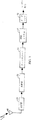
図1を参照すると、データ源2がディジタルデータのフレームを提供する。例示的実施例において、データ源2は毎20msのフレームを提供するが、本発明は他の率でも等しく応用可能である。例示的実施例において、データ源2はフレームのビット数が時間で変化する可変率データ源である。例示的実施例において、データ源2は、例えば前述のU.S.特許No.5,414,796に記載された可変率音声符号器である。
U.S.特許No.5,414,796の音声符号器は、そのフレームにおけるサンプルのエネルギーに基づいてディジタル化された音声サンプルのフレームを符号化する率を選定する。これは送られるビットの数を減少し、ユーザが話さないとき、前述したようにCDMA通信システムにおける他のユーザにそのユーザの干渉を最小限にする。本発明が固定率データ源にも等しく適用可能であることは注目されるべきである。さらに本発明は音声の他に、ファクシミリ、ビデオまたは他のディジタルデータのような他のディジタル情報を伝送するために等しく適用可能である。
データ源2からの情報ビットのフレームはフレームフォーマッタ4に提供される。例示的実施例において、フレームフォーマッタ4はCRC発生器6および末尾ビット発生器8からなる。CRC発生器6はデータ源2からフレームに提供される情報ビットに従って一組の冗長検査ビットを発生し、フレームに冗長ビットを付加する。本発明は他の冗長検査ビット発生器に適用可能であり、冗長ビット即ちパリティビット発生器の設計および実行はこの技術において良く知られている。CRC発生器6の例示的実施例は前述のU.S.特許No.5,414,796に記載され、かつIS−95に標準化された。技術に普通に熟練した者により理解されるように、本発明は他の冗長ビット発生器に等しく適用可能であることが注目されるべきである。
情報ビットとCRCビットを備えたフレームは一組の末尾ビットを発生しかつこれらのビットをフレームに付加する末尾ビット発生器8に提供される。末尾ビットの目的はフレームがそれを通過し終わるとき、予定の状態に符号化器10を附勢することにある。例示的実施例において、末尾ビット発生器8は、符号化器10の出力をゼロ状態に附勢するように一組の末尾ビット値ゼロを発生する。
図2A−2Dを参照すると、本発明の例示的フレームフォーマットが示される。これらのフレームフォーマットはIS−95標準で標準化されたように多重化選択2フレームフォーマットとして参照される。本発明が他のフレームフォーマットを使用するデータ伝送の解読に等しく適用可能であることは技術に熟練した者に既に明らかである。
例示的実施例において、データ源2は4つの異なった率でデータを提供する。図2Aを参照すると、もしデータ源2が最大限の率フレームとして267情報ビットからなるフレームを提供するなら、そのときCRC発生器6は情報ビットに従って12CRCビット(表示F)を発生し、フレームにこれらのビットを付加する。末尾ビット発生器8は値ゼロの8末尾ビット(表示T)を発生し、これらのビットをフレームに付加する。取っておかれたビット(表示R)はフレームの最初に設けられ、例えば伝送パワーを制御するために使用され得る。
図2Bを参照すると、もしデータ源2が半分の率フレームとして125情報ビットからなるフレームを提供するなら、そのときCRC発生器6は情報ビットに従って10CRCビット(表示F)を発生し、フレームにこれらのビットを付加する。末尾ビット発生器8は値ゼロの8末尾ビット(表示T)を発生し、これらのビットをフレームに付加する。取っておかれたビット(表示R)はフレームの最初に設けられ、例えば伝送パワーを制御するために使用され得る。
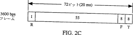
図2Cを参照すると、もしデータ源2が四分の一の率フレームとして72情報ビットからなるフレームを提供するなら、そのときCRC発生器6は情報ビットに従って8CRCビット(表示F)を発生し、フレームにこれらのビットを付加する。末尾ビット発生器8は値ゼロの8末尾ビット(表示T)を発生し、これらのビットをフレームに付加する。取っておかれたビット(表示R)はフレームの最初に設けられ、例えば伝送パワーを制御するために使用され得る。
図2Dを参照すると、もしデータ源2が八分の一の率フレームとして36情報ビットからなるフレームを提供するなら、そのときCRC発生器6は情報ビットに従って6CRCビット(表示F)を発生し、フレームにこれらのビットを付加する。末尾ビット発生器8は値ゼロの8末尾ビット(表示T)を発生し、これらのビットをフレームに付加する。取っておかれたビット(表示R)はフレームの最初に設けられ、例えば伝送パワーを制御するために使用され得る。
フレームフォーマッタ4からのフレーム出力は符号化器10に与えられる。例示的実施例において、符号化器10は制約長9(k=9)の率1/2畳み込み符号化器である。通常の符号化器の設計および実行はこの技術においてよく知られている。符号化器10から符号化された符号はインタリーバ12に提供される。
例示的実施例において、インタリーバ12は符号データがフレームの最大限容量を占めるようにフレームに冗長を選択的に提供する。もしフレームが最大限率より少ないなら、インタリーバ12は符号の複製を提供する。かくして、もしフレームが半分の率なら、インタリーバ12は符号の単一原文コピーとこれらの符号の複製を含んでいる各フレームで率2の冗長を提供し、もしフレームが四分の一の率なら、インタリーバ12は符号の単一原文コピーとこれらの符号の3複製を含んでいる各フレームで率4の冗長を提供し、もしフレームが八分の一の率なら、インタリーバ12は符号の単一原文コピーとこれらの符号の7複製を含んでいる各フレームで率8の冗長を提供する。符号反復の後、IS−95標準に記載されたように与えられた符号数を得るために、それらは毎6符号中2符号を削除することにより穴をあけられる。それからインタリーバ12は予定の再整理フォーマットに従って符号を再整理する。例示的実施例において、インタリーバ12は冗長を提供し、かつIS−95標準に記載されたようにフレームを再整理する。
修正された符号は予定の変調フォーマットに従って符号を変調する変調器14に与えられる。例示的実施例において、変調器14は前述のU.S.特許No.4,901,307およびNo.5,103,459に詳細に説明されたようにCDMA変調器である。データの変調されたフレームはフレームをアップ変換しかつ増幅しそしてアンテナ20を経てフレームを送信する送信機16に提供される。
図3を参照すると、図1の伝送システムにより送信された信号はアンテナ49により受信され、受信機(RCVR)50に与えられる。受信機50は受信信号をダウン変換し、フィルタにかけかつ増幅し、それを復調器52に供給する。復調器52は予定の復調フォーマットに従って受信した信号を復調する。例示的実施例において、復調器52は前述のU.S.特許No.4,901,307およびNo.5,103,459に詳細に説明されたようにCDMA復調器である。
データの復調されたフレームはデインタリーバ54に供給され、それはフレームのソフト符号データを予定の再整理フォーマットに従って再整理し、かつ逆フレームフォーマットを得るために符号が送信工程において削除された位置にゼロを加える。ソフト決定符号データの逆フレームは解読システム56に供給される。解読システム56はデータを解読し、解読されたデータをデータシンク58に提供する。データシンク58はデータの解読されたフレームに後処理を提供してもよい。例えば、もしデータが圧縮された音声データであるなら、データシンク58はU.S.特許No.5,414,796に説明されたように、予定の拡張フォーマットに従って音声パラメタをディジタル化された音声サンプルに変換する。
図4は本発明の解読システム56の第1の例示的実施例の装置を示し、図5は本発明の第1の例示的実施例の方法を示す付随的フローチャートを提供する。図4および図5に示されたように、デインタリーバ54(図3)からの修正されたソフト符号データのフレームはブロック230に供給され、フレームバッファー220(図4)に記憶される。
それから、ブロック252において、符号は現在の率仮説に従って符号結合器222で束ねられる。結合工程は最大限の率より少ない率のため送信された符号データに冗長があるという事実の利点を取り、そこで送信された符号データのより良い推定がその符号の全ての冗長コピーのエネルギーを合計することにより到着され得る。符号の改良された推定を発生する工程は、前述されたU.S.特許出願No.08/126,477に詳細に開示される。
例示的実施例は第1にフレームが最大限の率で送信されたとの仮説を試験する。最大限率仮説のもとで、符号反復が存在せず、符号データの結合も行われない。ブロック254において、符号結合器222からのデータは変調されたバイタービ解読器224に提供される。例示的実施例において、変調されたバイタービ解読器224はバイタービ解読器であるが、技術に熟練したものはトレリス解読器の他の形が同様に適用可能であることを認識するであろう。バイタービ解読器の設計および実行は技術において知られており、バイタービ解読器の特別な実行は前述されたU.S.特許出願No.08/126,477に詳細に開示される。
変調されたバイタービ解読器224は送信された情報ビットおよびフレームのCRCビットの推定を計算し、そのフレーム推定をCRC試験サブシステム232に提供する。ブロック256において、CRC試験サブシステム232はCRC発生器6に関して記載されたように、解読された情報ビットから一組の冗長ビットを発生する。CRC試験サブシステム232は情報ビット推定から発生されたCRCビットを変調されたバイタービ解読器224からの冗長ビットの推定と比較する。比較の結果はCRC試験が通過したか否かを決定する制御処理装置234に供給される。
もし、ブロック258において、CRC試験が通過するなら、方法はブロック266に進む。ブロック266において、符号誤差率(SER)計算器228が解読されたフレームの符号誤差率を計算する。SER計算器228は受信された符号データのハード決定推定を発生し、または変調されたバイタービ解読器224からのハード決定推定を発生する。それから、SER計算器228は変調されたバイタービ解読器224からのフレームの解読されたデータを受け、一組の再符号化された符号データを発生するため、符号化器10(図1)により行われる同じ符号化作動を使用しているフレームを符号化する。再符号化符号データはハード決定符号データと符号毎に比較され、二組の符号データ間の不一致の数が符号誤差率であり、それはブロック268における選択器230に供給される。
この実施例において、出力バッファー226は率仮説の解読についてCRC試験が通過された後のみ選択器230に解読された符号データを供給する。好ましい実施例において、変調されたバイタービ解読器224は率選択を援助するため選択器230にメートル法データを提供する。選択器に提供されるメートル法データは単一ビットヤマモトメートル法または総メートル法でありうる。
もしCRC試験がブロック258で失敗したなら、ブロック260において制御処理装置234は現在の率仮説のもとでフレームを解読することでなされる試みの数の係数を増加する。ブロック262において、制御処理装置234はフレームを解読する試みの数が、現在の率仮説におけるフレームを解読する試みの予定の最大数に到達したか否かを決定する。もし試みの最大数が到達されたなら、方法はブロック264に進み、制御処理装置234は選択器230にフレームが現在の率仮説のもとで解読できないことを指示する信号を供給する。
もし制御ブロック262において、現在の率でフレームを解読する試みの最大数が到達されなかったなら、制御処理装置234は変調されたバイタービ解読器224に伝言を供給する。制御処理装置234からの伝言に応答して、ブロック278において、変調されたバイタービ解読器224はその経路係数(i)を1だけ増加する。それからブロック254において、変調されたバイタービ解読器224はトレリスを通るi番目の最良の経路を発見する。方法はブロック256に進み、工程は前に説明されたように繰り返す。
ブロック270において、制御処理装置234は全ての可能な率が試験されたか否かを決定する。もしされてないなら、方法は試験されるべき次の率を選択するブロック272に進み、それから方法はブロック252に進んで次の率仮説が試験される。制御処理装置234からの信号に応答して、フレームバッファー220が符号結合器222にフレームデータを供給する。制御処理装置234は符号結合器222に試験されるべき率仮説の信号指示を提供する。ブロック252において、符号結合器222は試験されるべき率仮説に従って符号データを結合する。方法はブロック254に続き上述のように進む。
もしブロック270において、全ての率が試験されたなら、ブロック274において、選択器230はデータが送信される最もありそうな率を決定し、ブロック276にその率に対応しているデータを提供する。選択器230は悪い質測定によるフレームを消去する決定をするかもしれない。例示的実施例において、選択器230は解読されたフレームとメートル法データ値との差の符号誤差率に基づいて率を決定する。
第1の例示的実施例の付加的な経路捜査を行うため、多くの方法が採用される。しかし、多くの方法はあまりにも多くの記憶のためのメモリを必要とする。第1の例示的実施例の方法を参照すると、方法はメモリの量および経路捜査に必要な時間を減少するように適用される。例えば、1つの方法は変調されたバイタービ解読器224を実行しているとき出会う最良経路のあるメートル法閾値以内にある全ての経路を解読することである。
まずトレリス解読動作の簡単な評価を図6,7、および8に表わす。図6は制約長さk=3トレリス解読器における状態変移の可能性を示す。トレリス解読器における可能性のある状態(S)の数は式により与えられる。
S=2k-1 (1)
かくして、図6において、k=3で4つの状態がある。図9を参照すると、符号器の状態は点300および310でビットの値により定義され得る。4つのこのような状態がある。つぎのビットが点300に動くとき、点300の値は点310に動き、点310の値は説明されるであろう。
各状態がその状態でその時における残存手順の可能性に逆比例する状態メートル法を構成するので、より高いメートル法は可能性が少なくなりがちである。各状態の状態メートル法は図6に初期状態について丸括弧にある。加えて、時間Nでの1つの状態から時間N+1での他の状態に状態変移の可能性に逆比例する構成された分岐メートル法がある。例えば初期状態01(点290)に見られるように、もし符号化器を符号化している次のビットが0であるなら、時間N+1に符号化器の状態は00(点292)になるであろう。ところが、もし初期状態が01(点290)でありかつ符号化器に入る次のビットが1ならN+1での状態は10(点294)になるであろう。
時間N+1での状態メートル法の値はその状態に変移のため分岐を有する時間N+1で初期状態の状態メートル法を加えることにより計算される。より低い状態メートル法にもたらす分岐は選択され、その状態に導く他の分岐は捨てられる。図7において、図6の状態および分岐メートル法に従って選択された分岐が図示される。N+1時間に新しく計算された状態メートル法がまず丸括弧で示され、それから起こった選択された変移からの状態の値が示される。
例えば、もし時間N+1で状態00(点292)の状態メートル法を計算することを欲するなら、状態00に導く2つの経路がある。率1/nの符号化器、または率1/nの符号化器のデータ流を穴あけすることに基づいた符号化器が使用されるとき、これが常にその場合であることに注目せよ。1つの経路は状態01(点290)から導く。状態01(点290)での状態メートル法は6であり、状態00(点292)に変移のため構成された分岐メートル法は値10を有する。それ故、時間N+I(点292)における点状態00の状態メートル法は、もし分岐が選択されるなら、値16を持つことになる。第2の経路は状態00(点288)から導く。状態00(点288)での状態メートル法は4であり、かつ状態00(292)に変移のため構成された分岐メートル法が値2を有する。それ故、時間N+I(点292)における点状態00の状態メートル法は、もし分岐が選択されるなら、値6を持つことになる。状態00(点288)からの分岐が選択され、かつその状態は構成された状態メートル法6である。
図8はトレリスを通る選択された経路を示す。末尾ビットにより最後の状態が知られる。なぜなら、例示的実施例において、末尾ビットは全てゼロであり、最後の状態はすべてゼロ状態にあることが知られる。この状態に導く1つの経路のみがあるので、選択された経路はその知られた状態に導く経路である。一度経路が知られたなら、データは、解読器が選択された経路に沿ってさかのぼるチェインバック動作の手段により出力され、かつ選択された変移にもたらされたビットを出力する。例えば、状態10から状態11への変移において、ビット出力は値1を持つ。これはトレリスを通す最良の経路を選択する方法である。次に最適な経路の選択は以下により十分に議論されるように残される。
本発明の第1の例示的実施例の解読器224が図10に示される。符号結合器(示されない)からの結合された符号はメートル法計算器350を分岐するために提供される。分岐メートル法計算器の設計および実行はよく知られた技術である。加算比較選択(ACS)要素354は分岐メートル法計算器350からの分岐メートル法に従って、図10および11を参照して上述されたように状態メートル法の値を決定する。新しく計算された状態メートル法はそれから状態メートル法メモリ352に記憶され、選択された分岐の指示はチェインバックメモリ358に供給される。全ての状態メートル法がフレームのため計算されるとき、チェインバックメモリ要素358は、チェインバック制御360の制御のもとで、上述のようにトレリスを通す最適の経路を選択し、CRCビット検査要素(示されない)に解読されたデータを出力する。
もしCRC試験が失敗すると、そのときトレリスを通る二番目の最良な経路が決定される。トレリスを通る最良の経路を見つけるアルゴリズム(即ち、バイタービアルゴリズム)が再実行される。しかし、図示した実施例によれば、上述のステップに加えて、トレリスを通る最良の経路および各時点で拒絶された経路間の距離の測定が計算され、Δ分類メモリ356に分類される。もし拒絶された経路が選択され、かつ選択された経路(p)の状態(s)のメートル法の値であるなら、Δs,pの値は状態(s)のメートル法の値と異なった値である。
Δs,p=拒絶された経路の状態メートル法−選択された経路の状態メートル法
Ds,pの例が図11に示される。どの経路も経路に関して測定された値Dpで構成される。Dpの値はその経路が合併するより良い経路のDpと合併点Ds,pにおけるメートル法の差により与えられる。かくして、最良経路のDpの値(即ち、バイタービアルゴリズム)はゼロである。
D分類手段356はD値の最小Dminを決定する。Dminが見出された点で、チェーンバック動作が分岐のその点に導いた経路を決定するために実行される。図12を参照すると、状態メートル法計算工程が述べられたように再実行され、最小経路差がD記憶手段356により点362でD5,1に見出された。チェーンバック制御器360の制御のもとでチェーンバックメモリ358は、点362から二番目に最良な経路および対応する解読されたデータシーケンスを決定する。これは最良経路に対応しているデータに最初のN+6データビットを置換することにより得られる。好ましい実施例において、チェーンバック動作は、少数の制約長さより長い誤りの場合が稀にあるので、経路分岐の点の少数の制約長さ以内に切り詰められる。図12において、これは点364で起こる。図12における二番目の最良な経路のDpの値はDp=D5,1である。
三番目に良い経路を見出すため、同じ状態メートル法計算工程が第3回として行われ、Ds,p値が上述のように計算されるが、今回それらは二番目に最良の経路に関して経路選択のため計算される。これらは二番目に最良の経路が最良の経路と合併する前に,その回数例までのみ計算される必要がある。言いかえれば、その回数例は図12および13においてN+5である。図13を参照すると、ACS354は二番目の経路(D0,2、D1,2、D2,2、D3,2およびD4,2)に必要な経路差値を計算する。これらメートル法の幾つかが予め計算されたかもしれないが再び考慮されねばならないことが注目されるべきである。比較値は二番目の最良な経路の距離に基づかなくて最良な経路の距離に基づく。かくして、D分類手段356に提供されるメートル法値としては、トレリスを通る最適経路に関係しなくてはならない。例えば、D4,2で示された経路のため比較のメートル法差を得るため、その経路のDp値はD4,2(二番目の経路からの距離)と第1経路に対する二番目の経路の距離D5,1との合計により計算されねばならない。ACS354は計算された値をD分類手段356に供給する。D分類手段356はそれから最良および二番目の最良の経路を合併する経路の最小のDp値を見出すことにより三番目の接近した経路を見出す。
図示した実施例において、D分類手段356は全てのDp値を記憶するのではなく、最小のM値のみを記憶する。ここにMは捜査される経路の最大数である。それから各続くi番目に良い経路のため、最小のM-i値のみが記憶されねばならない。
代わりの実施例において、解読工程は各次に最適な経路を見出すために戻るのではなく、むしろ状態メートル法が記憶され、各経路捜査のために再使用される。これは計算数を減少するが必要なメモリ量を増加する。図11−13に図示された例は図示の目的のために非常に単純化される。例示的実施例において、フレームの大きさは情報の288ビットであり、コードの長さは256状態を含む9(k=9)である。かくして、状態メートル法の推定記憶容量は情報の略1バイトを必要とし、状態毎に状態メートル法を記憶するために必要なメモリは、5ビット状態メートル法として、略74キロバイトのメモリを必要とする。
図14は本発明の解読システム56の第2の例示的実施例の装置を示し、図15は本発明の第2の例示的実施例の方法を示す付随フローチャート500を提供する。ブロック550において、再インタリーバ54からの修正されたソフト符号データのフレームはフレームバッファー420に提供されかつ蓄えられる。
それからブロック552において、符号は現在の率仮説に従って符号結合器422に結合される。結合工程は最大限の率より少ない率のため送信された符号データに冗長があるという事実の利点を取り、そこで送信された符号データのより良い推定がその符号の全ての冗長コピーのエネルギーを合計することにより到着され得る。符号の改良された推定を発生する工程は、前述されたU.S.特許出願No.08/126,477に詳細に開示される。
例示的実施例は第1にフレームが最大限の率で送信されたとの仮説を試験する。最大限率仮説のもとで、符号反復が存在せず、符号データの結合も行われない。ブロック554において、符号結合器422からのデータは変調されたバイタービ解読器424に提供される。例示的実施例において、変調されたバイタービ解読器424はバイタービ解読器であるが、技術に熟練したものはトレリス解読器の他の形が同様に適用可能であることを認識するであろう。バイタービ解読器の設計および実行は技術において知られており、バイタービ解読器の特別な実行は前述されたU.S.特許出願No.08/126,477に詳細に開示される。本実施例において、バイタービ解読器424は分岐メートル法計算器450を含む。符号結合器422から結合された符号は分岐メートル法計算器450に供給される。分岐メートル法計算器の設計および実行は良く知られた技術である。加算比較選択(ACS)要素454は分岐メートル法計算器450からの分岐メートル法に従って、図6および7を参照して上述されたように状態メートル法の値を決定する。新しく計算された状態メートル法はそれから状態メートル法メモリ452に記憶され、選択された分岐の指示はチェインバックメモリ458に供給される。全ての状態メートル法がフレームのため計算されるとき、チェインバックメモリ要素458は、チェインバック制御460の制御のもとで、上述のようにトレリスを通る最適の経路を選択し、CRCビット検査要素432に解読されたデータを出力する。ブロック554において、カウンタiとmの値が1に設定される。解読器実行の数がiによって表わされ、CRCが検査される経路の数がmにより表わされる。
変調されたバイタービ解読器424はそれによりフレームにおける送信された情報ビットおよびCRCビットの推定を計算する。ブロック556において、CRC試験サブシステム432は、図1のCRC発生器6に関して記載されたように、解読された情報ビットから一組の冗長ビットを発生する。CRC試験サブシステム432は情報ビット推定から発生されるCRCビットを変調されたバイタービ解読器424からの冗長ビットの推定と比較する。その比較の結果は制御処理装置434に供給される。
もし、制御ブロック558において、CRC試験が通過するなら、方法はブロック570に進む。ブロック570において、符号誤差率(SER)計算器428は解読されたフレームのため符号誤差率を計算する。SER計算器428は受信した符号データのハード決定推定を発生し、変調されたバイタービ解読器424からのハード決定推定を受ける。それから、SER計算器428は変調されたバイタービ解読器424からのフレームの解読されたデータを受け、一組の再コード化符号データを発生するため、符号化器10により遂行された同じ符号化動作を使用してフレームを符号化する。再コード化符号データは符号毎にハード決定符号データと比較され、二組の符号データ間の不一致の数がブロック570で選択器430に提供される符号誤差率である。
例示的実施例において、出力バッファー426は率仮説の解読についてCRC試験が通過された後のみ選択器430に解読された符号データを供給する。好ましい実施例において、変調されたバイタービ解読器424は率選択を援助するため選択器430にメートル法データを提供する。選択器に提供されるメートル法データは単一ビットヤマモトメートル法または総メートル法でありうる。
もしCRC試験がブロック558で失敗したなら、ブロック560において変調されたバイタービ解読器424は与えられた率仮説のため符号データ422に第2の実行を行う。この実行において、変調されたバイタービ解読器は前の実行でバイタービ解読器により発見された最もありそうな経路を処理すると言われる。ACSブロック454は計算された分岐メートル法450により状態メートル法452を更新するトレリスを通して進行するが、この標準バイタービ解読手順に加えて、Δ分類回路456に出力し、全ての経路のメートル法が出力バッファー426によりACSに適用される処理された経路(解読器の第2実行のための最良経路)と合併する。チェーンバック制御460はこの経路で構成されたデータシーケンスを得るためにチェーンバックを行う。チェーンバックは経路のメートル法がある基準閾値を満たす場合のみ行われる。この閾値基準は以下に説明される。この手順に見出された経路は出力バッファー426に記憶される。
ブロック562はブロック560により見出されかつバッファー426に記憶された経路のCRCをCRC検査器432で検査する。CRC検査の結果は制御器434により注目される。ブロック562において、制御処理装置434はこの率仮説のため発見された経路数mを増加する。ブロック586において、制御処理装置434は変調されたバイタービ解読器424により遂行された実行数iを増加する。
もし制御ブロック556において、実行の最大数がいまだ到達しなかったなら、制御処理装置434は、既に見出された経路であって、変調されたバイタービ解読器424がまだ処理していなかった経路(即ち、それと合併している経路がまだ発見に企てられなかった)があるか否かをブロック582で検査する。もしそのような経路がないなら、ブロック584において、制御器434は、この率仮説の経路が解読器によって見出すことが出来ないことを選択器430に指示する。
もしブロック582において、既に見出され、変調されたバイタービ解読器424がまだ処理していなかった経路まだあるなら、未だ処理されていなかったi番目の最もありそうな経路のCRCが通過するCRCを有するか否かを検査するため、解読器はブロック556に進める。もしCRCが制御ブロック558において失敗するなら、制御器434はi番目の最良な経路を処理するように変調されたバイタービ解読器424に指示する。これは既に述べたようにブロック560において成される。
もしブロック582において、見出された、しかしまだ処理されなかった経路がないなら、解読器はこの率仮説の経路が発見出来なかったことを選択器430に指示するブロック584に進める。もし制御ブロック566において、実行の最大数が到達されたなら、制御処理装置434は、もし発見された経路がCRC検査器432により遂行されるCRCを通過するならブロック568において検査する。もし通過するCRCを有する経路があるなら、方法はブロック570に進む。
ブロック574において、制御処理装置434が全ての可能な率が試験されたかどうかを決定する。もしそうでないなら、そのとき方法は試験されるべき次の率を選択するブロック576に進み、それから方法はブロック552に進んで次の率仮説が試験される。制御処理装置434からの信号に応答して、フレームバッファー420はフレームデータを符号結合器422に提供する。制御処理装置434は試験されるべき率仮設の指示信号を符号結合器422に供給する。ブロック552において、符号結合器422は試験されるべき率仮設に従って符号データを結合する。方法はブロック554に進み、上述されたように進行する。
もしブロック574において、全ての率が試験されたなら、ブロック578において選択器430はデータが伝送された最もありそうな率を決定し、その率に対応するデータをブロック580に供給する。選択器430は悪い質測定によるフレームを消去する決定をしてもよい。例示的実施例において、選択器430は解読されたフレームとメートル法データ値との差の符号誤差率に基づいた率を決定する。
図16は本発明の次に最適な経路を選択するための閾値技術を示す第2の例示的実施例の方法のフローチャートである。フローチャートはある与えられた率仮説の経路検索のみを示す。以下の定義が本発明の理解を容易にするために有用である。
p−トレリスの経路、ここにそれはその情報シーケンスにより与えられる;
yp−最良の経路に関する経路pのメートル法;
lp−経路pの最も小さい分岐点;
F−データのm経路の列、それはそれらの情報シーケンス(p)、それらのメートル法(yp)およびそれらの最も小さい分岐点(lp)を含む;
Δ(p)−経路pと合併する経路のヤマモトメートル法のベクトル;
Δi(p)−ベクトルΔ(p)のi番目の値;
t−閾値、考慮された全ての経路がtより少ないメートル法を有する;
q−他の経路(p)から分岐する経路、これらの経路は列Nに記憶される;
T−経路の一時的メモリ;
C−通過するCRCを有する経路のメモリ;および
‘部分的チェーンバック’−分岐点からのチェーンバックの有限長。分岐情報シーケンスは、それが分岐するところから経路における出力ビットの有限数を変更するときのみ得られる。
この実行の2つの主パラメタは、閾値tとACS機構が再実行される回数mである。パラメタnは全般的に小さく、2から4の程度である。
与えられた率の解読のため、手順はブロック610で開始し、変調されたバイタービ解読器424が標準バイタービ解読を行う。ACS454は状態メートル法452を最新にし、決定ビットをチェーンバックメモリ458に出力する。CB機構460は出力バッファー426に設置されたメモリ列Fに解読されたデータシーケンスを出力するためチェーンバックを遂行する。標準バイタービ解読のこの点までは技術に熟練した者により認識されるように使用されていた。最良の経路と結合される2つのメートル法があり、それらは、明らかにゼロである最良の経路yp'に関するメートル法、およびフレーム長に等しい最小分岐点lp'である。これら2つのパラメタの意味は以下に明らかになるであろう。
ブロック612において、制御処理装置434は出力バッファー426に設置されたメモリ列Fにおいて第1の経路とそのパラメタを同一視する。この経路はpにより表わされる。解読の第1の実行のためこれが最良の経路である。
ブロック614において、ブロック612で同一視された経路のCRCがCRC機構432により検査される。もしCRCが通過するなら、手順はブロック616に進み、フレームの解読が終了する。図16に特別には示されないが、フレームに関する他のデータ、例えば再符号化SER428または解読されたありそうなメートル法が出力およびまたは計算されてもよい。
もしブロック614のCRC検査が失敗したなら、ブロック618の制御器434は経路pで合併する経路を発見するため変調された解読器424に戻る。ACS454は状態メートル法計算を行い、トレリスの点lp'まで452を最新にする。通常の加算、比較および選択に加えて、変調された解読器424は特別な機能を遂行する。これはq'で表わされた経路のヤマモトメートル法の値をΔ分類回路456に出力することであり、それは各索引jで索引lp'までトレリスの経路Pと合併する。索引
![]()
部分的チェーンバックの遂行およびブロック618における閾値に従って新シーケンスの獲得の後、手順はブロック620に続く。ブロック620において、制御434は出力バッファー426のシーケンスの位置を認識する。列TはNに設置された最も可能性のある経路および見出された新しい経路を前のmの統合であるとして定義される。Tの最もありそうな経路mは新しい列Fとして定義される。
手順はそれからブロック622に進み、そこで発見された新経路の全てのCRC432が検査される。Tにおけるこれらの新しい経路は列Nとして明らかに定義される。もしいずれかの経路が検査するCRCを有するなら、経路およびそのメートル法はCにより表わされた列に保持される。ブロック622で遂行される手順が同時にブロック618における手順に遂行され得ることは技術に熟練した者に明らかである。T,F,NおよびCにより表わされた列がメモリ割当て列として定義される必要がないが、出力バッファーに記憶されたシーケンスへの指針であることも明らかである。これらの列は手順の明確な説明のため限定される。
もしブロック624において、解読器実行の最大数が到達され(m=1)、または閾値基準(Fは空)に適合する処理されるべきシーケンスがもはやないなら、制御処理装置434がブロック628に進む。もしブロック628において、通過したCRCを有し、即ち列Cが空であるシーケンスがないなら、制御処理装置434は現在の率仮説の解読工程を終了し、シーケンスが発見されないことを選択器430に送信する。制御処理装置434は、その決定に選択器430を援助するため、不成功に解読された率仮説、例えばありそうな最良経路のメートル法に関わるデータを選択器430に出力してもよい。
もしブロック628におい他方Cが空でないなら、工程はブロック630に進み、そこで制御処理装置434はCRC検査を通過する最小のメートル法を有する経路を選択器430に出力する。選択器430は解読されたフレーム、例えばSER428およびその経路のメートル法に関わる他のデータに適用されてもよい。
もしブロック624において、実行の最大数が解読器により到達されなかった(m>1)、および処理されるべきシーケンスがある(Fは空でない)なら、制御処理装置434はmを減少し、次に最もありそうなシーケンス(Fにおける第1のシーケンス)の処理を継続するため、手順がブロック612に継続される。
図17は本発明の解読方法の第2の例示的実施例により探知された経路のトレリス図である。図17において、最良の経路(伝送された正確なものではなくて、バイタービ解読器424により出力されたもの)が厚い破線により描かれる。方法は最良の経路のCRCが検査しないことを想定することにより描かれてもよい。解読器の最初の再実行において、閾値以下のメートル方を有する3つの経路が見出される。それらの分岐点はi,j,およびkであり、情報シーケンスを限定する。これらは最良の経路から一度分岐する経路である。点jで分岐する経路が最小のメートル法を有し、かつそのCRCが検査されないと想定する。この経路から分岐する経路を見ると、2つの経路が見出され、かつ閾値より小さい総メートル法を有する。これらの経路はj'およびj"である。今解読器の第2の再実行が行われる。この時、一組の経路i,k,j'およびj"の外に最小メートル法を有する経路から分岐する経路が試験される。k経路が最小メートル法を有し、かつそのCRCが検査しないと想定する。kから分岐する経路は後で探求される。図において、閾値k',k",およびk"'より小さいメートル法を有する3つの経路がある。
与えられた経路を分岐する経路のための必要な捜査時間は、それが分岐点まで解読器を実行するにただ必要であるので一定ではない。上記例の解読周期は以下の表にまとめられ得る。

非常に信頼すべきCRC(多くのビット)の場合に、良いCRCを有する最初のシーケンスが発見されたとき、解読工程は停止され得る。信頼できないCRCの場合、時間の許すかぎり(次のフレームの到着)経路が見出され、通過するCRCを有する全ての経路が保持され、解読器は最も小さいメートル法を有する良いCRCの経路に決定する。
好ましい実施例の前記説明は、技術に熟練したどんな者にも本発明を作りまたは使用することの可能性を提供する。これらの実施例に対する種々の変形例がこれらの技術に熟練した者にすでに明確であり、ここに定義された基本的原理は発明の能力を使用することなく他の実施例に適用され得る。かくして、本発明はここに示された実施例に限定されるべきものではなく、原理およびここに開示された新規な特徴を構成する最も広い範囲に従うべきである。Background art
I. Field of Invention
The present invention relates to digital signal processing. In particular, the present invention relates to a new and improved method and apparatus for decoding frames of digital data containing redundant check bits or any outside information known about the data.
II. Explanation of related technology
With the development of wireless communication technology, users have demanded higher transmission characteristics for the services provided. One means of providing high transmission quality is that the service involves the use of digital transmission technology. Several digital modulation techniques are known as techniques including code division multiple access (CDMA), time division multiple access (TDMA), and frequency division multiple access (FDMA).
CDMA spread spectrum modulation techniques have significant advantages over other digital modulation techniques. The use of CDMA technology in a multiple access communication system is assigned to the assignee of the present invention and is incorporated herein by reference as “a spread spectrum multiple access communication system using satellites or terrestrial repeaters”. Patent No. 4,901,307. The use of CDMA technology in a multiple access communication system is further assigned to the assignee of the present invention and is incorporated herein by reference as “System and Method for Generating Signal Waveforms in a CDMA Cellular Telephone System”. Patent No. 5,103,459. A method for providing digital wireless communications using CDMA has been standardized by the Telecommunications Industry Association (TIA) as a TIA / EIA / IS-95-Dual Mode Wideband Spread Spectrum Cellular System (hereinafter IS-95).
In a CDMA communication system, each user's transmission contributes to increased noise in the transmission of other users, so the capacity of the CDMA system is maximized by having each user only transmit as much data as necessary. A very effective means of reducing the user's burden on capacity without reducing the quality of service to the user is the means of variable rate data transmission, where the data rate of transmission by the user varies with time. A method for providing variable rate decoding of voice data is assigned to the assignee of the present invention and is incorporated by reference herein in the form of a US patent no. No. 5,414,796 is disclosed in detail.
Digital error correction techniques are employed in wireless communication systems to protect against channel induced errors. One way to detect and correct channel guidance errors is to employ trellis decoding. The Viterbi decoder is a special type of trellis decoder that exhibits significant advantages over other error correction systems. A method and apparatus for performing Viterbi decoding of variable rate data is filed September 24, 1993, entitled "Multiple Rate Continuous Viterbi Decoder for CDMA Systems", assigned to the assignee of the present invention and incorporated herein by reference. U.S. Patent Application No. 08 / 126,477 is disclosed in detail.
However, there remains a need in the system and technology to further improve the code gain provided by CDMA modulation techniques, thereby achieving increased system capacity.
Summary of the Invention
The present invention is a new and improved method and apparatus for decoding a frame of digital data containing redundant information provided to verify the decoding operation. The present invention improves the coding gain of CDMA systems and results in increased system capacity. In the present invention, a frame of data is provided including information bits and cyclic redundancy check (CRC) bits. The received frame is decrypted and a check is introduced to determine if the CRC bits correspond exactly to the decrypted information bits. If the decrypted frame passes the CRC test process, the decrypted frame is provided to the user. However, if the decrypted frame does not pass the CRC test, at least one additional decryption step is performed on the received frame.
In the first exemplary embodiment of the present invention, the data is decoded using a trellis decoder and the data that provides the path most likely to pass through the trellis is selected. A CRC test is then performed on the decoded frame of data. If the CRC test fails, the trellis decoder determines the path most likely to pass the trellis. The CRC test is then performed a second time on the decoded frame. If the decoded frame passes the CRC test, the information bits are output by the decoder. However, if the decoded frame fails the CRC test, then the trellis decoder then determines the path that is most likely to pass the trellis. This process is until the CRC test passes successfully, or the scheduled number of decryption attempts is unsuccessful, the decryptor declares it impossible to decrypt the frame, and the frame deletion is declared Repeat until
In the second illustrated embodiment, the data is decoded using a trellis decoder and the data that provides the path most likely to pass through the trellis is selected. A CRC test is then performed on the decoded frame of data. If the CRC test fails, the trellis decoder identifies a path that has a metric within a predetermined metric threshold associated with the optimal path through the trellis. A CRC test is then performed on the decoded frame for the next optimal path. If any of these paths passes the CRC test, the information bits corresponding to the most likely path are output by the decoder. If not, an error is declared. As a preferred implementation, the decoding is done with a Viterbi decoder and the metric used is the Yamamoto metric.
[Brief description of the drawings]
The features, objects and advantages of the present invention will become more apparent from the detailed description set forth below when taken in conjunction with the drawings, in which like reference characters designate corresponding identical objects.
FIG. 1 is an exemplary transmission system for transmitting data in a frame including a set of CRC bits and a set of information bits.
2A-2D are exemplary diagrams of the variable rate frame structure of the present invention;
FIG. 3 is an exemplary implementation of the decoder of the present invention,
FIG. 4 is a block diagram of a first exemplary embodiment of the decryption system of the present invention,
FIG. 5 is a flowchart illustrating the method of decryption data of the first exemplary embodiment,
FIG. 6 is a diagram of state transitions in the trellis decoder.
FIG. 7 is a diagram of selected paths in the state transition trellis of FIG.
FIG. 8 is a diagram of routing through a trellis decoder.
FIG. 9 is a diagram of an encoder with four possible states,
FIG. 10 is a block diagram of the trellis decoder of the first exemplary embodiment;
FIG. 11 is a diagram of the best path through the trellis and the calculated path selection of different values associated with that path;
FIG. 12 is a diagram of the second best route selected by the first embodiment,
FIG. 13 is an illustration of different values of calculated routing associated with the first and second selection paths and the third path selection process through the trellis;
FIG. 14 shows the apparatus of a second exemplary embodiment of the decryption system of the present invention,
FIG. 15 is a flow chart illustrating the method of the second exemplary embodiment of the present invention,
FIG. 16 is a flowchart illustrating a threshold technique for selecting the next optimal route of the present invention,
FIG. 17 is a trellis diagram showing paths confirmed by the second exemplary embodiment of the decoding method of the present invention.
Detailed Description of Reference Example
The illustrated embodiments and exemplary applications will now be described with reference to the accompanying drawings to disclose the advantageous techniques of the present invention.
While the present invention will be described herein with reference to the illustrated embodiments for particular application, it should be understood that the invention is not limited thereto. Those skilled in the art and having access to the techniques provided herein will recognize additional variations, applications, and examples within the scope and additional fields where the invention is of significant utility. Let's go.
Referring to FIG. 1, a
US Patent No. The 5,414,796 speech encoder selects the rate at which a digitized frame of speech samples is encoded based on the energy of the sample in that frame. This reduces the number of bits sent and minimizes the user's interference to other users in the CDMA communication system as described above when the user does not speak. It should be noted that the present invention is equally applicable to fixed rate data sources. Furthermore, the present invention is equally applicable for transmitting other digital information such as facsimile, video or other digital data in addition to voice.
A frame of information bits from the
A frame with information bits and CRC bits is provided to a
2A-2D, an exemplary frame format of the present invention is shown. These frame formats are referred to as multiplexed
In the exemplary embodiment,
Referring to FIG. 2B, if
Referring to FIG. 2C, if
Referring to FIG. 2D, if
The frame output from the
In the exemplary embodiment,
The modified code is provided to a
Referring to FIG. 3, the signal transmitted by the transmission system of FIG. 1 is received by an antenna 49 and provided to a receiver (RCVR) 50.
The demodulated frame of data is fed to the
FIG. 4 shows the apparatus of the first exemplary embodiment of the
Then, at
The exemplary embodiment first tests the hypothesis that frames were transmitted at the maximum rate. Under the maximum rate hypothesis, there is no code repetition and no code data is combined. At
The modulated
If, at
In this embodiment,
If the CRC test fails at
If, in
At
If all rates have been tested at
A number of methods are employed to perform the additional route search of the first exemplary embodiment. However, many methods require too much memory for storage. Referring to the method of the first exemplary embodiment, the method is applied to reduce the amount of memory and the time required for pathfinding. For example, one method is to decode all paths that are within a certain metric threshold of the best path encountered when running the modulated
First, a simple evaluation of the trellis decoding operation is shown in FIGS. FIG. 6 shows the possible state transitions in the constraint length k = 3 trellis decoder. The number of possible states (S) in the trellis decoder is given by:
S = 2 k-1 (1)
Thus, in FIG. 6, there are four states at k = 3. Referring to FIG. 9, the encoder state may be defined by the value of the bits at
Higher metric tends to be less likely because each state constitutes a state metric that is inversely proportional to the probability of the remaining procedure at that time. The state metric for each state is in parentheses for the initial state in FIG. In addition, there is a configured branch metric that is inversely proportional to the possibility of a state transition from one state at time N to another at
The value of the state metric at time N + 1 is calculated by adding the initial state metric at time N + 1 that has a branch to transition to that state. The branch that leads to the lower state metric is selected and the other branches leading to that state are discarded. In FIG. 7, a branch selected according to the state of FIG. 6 and the branch metric is illustrated. The newly calculated state metric at N + 1 hours is first shown in parentheses and then the value of the state from the selected transition that occurred.
For example, if we want to calculate the state metric for state 00 (point 292) at time N + 1, there are two paths leading to
FIG. 8 shows the selected path through the trellis. The last state is known by the last bit. Because, in the exemplary embodiment, the last bit is all zero and the last state is known to be in the zero state. Since there is only one path leading to this state, the selected path is the path leading to its known state. Once the path is known, the data is output by means of a chainback operation that the decoder goes back along the selected path and outputs the bits that resulted in the selected transition. For example, in the transition from
A
If the CRC test fails, then the second best path through the trellis is determined. The algorithm that finds the best path through the trellis (ie, the Viterbi algorithm) is re-executed. However, according to the illustrated embodiment, in addition to the steps described above, a measure of the distance between the best path through the trellis and the path rejected at each point in time is calculated and classified in the
Δs, p = rejected path state metric—selected path state metric
An example of Ds, p is shown in FIG. Every path consists of a value Dp measured for the path. The value of Dp is given by the metric difference between the Dp of the better path where the paths merge and the merge point Ds, p. Thus, the value of Dp for the best path (ie the Viterbi algorithm) is zero.
The
In order to find the third best route, the same state metric calculation process is performed as the third and Ds, p values are calculated as above, but this time they are for route selection with respect to the second best route Calculated. These need only be calculated up to that number of times before the second best route merges with the best route. In other words, the number of times is N + 5 in FIGS. Referring to FIG. 13,
In the illustrated embodiment, the
In an alternative embodiment, the decoding process does not return to find the next best route, but rather the state metric is stored and reused for each route search. This reduces the number of calculations but increases the amount of memory required. The example illustrated in FIGS. 11-13 is greatly simplified for purposes of illustration. In the exemplary embodiment, the frame size is 288 bits of information and the code length is 9 (k = 9) including 256 states. Thus, the estimated storage capacity of the state metric requires approximately 1 byte of information, and the memory required to store the state metric for each state requires approximately 74 kilobytes of memory as a 5-bit state metric.
FIG. 14 illustrates the apparatus of a second exemplary embodiment of the
Then, at
The exemplary embodiment first tests the hypothesis that frames were transmitted at the maximum rate. Under the maximum rate hypothesis, there is no code repetition and no code data is combined. At
A modulated
If, at
In the exemplary embodiment, output buffer 426 provides decoded code data to
If the CRC test fails at
If, in
If at
If there are no paths found but not yet processed at
At block 574, the
If all rates have been tested at block 574,
FIG. 16 is a flowchart of a second exemplary embodiment method illustrating a threshold technique for selecting the next best path of the present invention. The flowchart shows only the path search for a given rate hypothesis. The following definitions are useful to facilitate understanding of the present invention.
the path of the p-trellis, where it is given by its information sequence;
y p The metric of path p with respect to the best path;
l p The smallest branch point of the path p;
A sequence of m-paths of F-data, their information sequence (p), their metric (y p ) And their smallest branch point (l p )including;
Δ (p)-a Yamamoto metric vector of paths that merge with path p;
Δ i (P) -i-th value of vector Δ (p);
t-threshold, all paths considered have metric less than t;
q—paths that branch off from other paths (p), these paths are stored in column N;
T-path temporary memory;
C-memory of the path with the passing CRC; and
'Partial chainback'-a finite length of chainback from the branch point. A branch information sequence is only obtained when changing a finite number of output bits in the path from where it branches.
The two main parameters of this execution are the threshold t and the number m of times that the ACS mechanism is re-executed. The parameter n is generally small, on the order of 2 to 4.
For a given rate decryption, the procedure begins at
In
In
If the CRC check at
![]()
After performing the partial chainback and acquiring a new sequence according to the threshold in
The procedure then proceeds to block 622 where all CRCs 432 of the new path found there are examined. These new paths in T are clearly defined as column N. If any path has a CRC to check, the path and its metric are kept in the column represented by C. It will be apparent to those skilled in the art that the procedure performed at
If, at
If at
If at
FIG. 17 is a trellis diagram of a path detected by the second exemplary embodiment of the decoding method of the present invention. In FIG. 17, the best path (not exactly transmitted but output by the Viterbi decoder 424) is depicted by a thick dashed line. The method may be drawn by assuming that the best path CRC does not check. In the first re-execution of the decoder, three paths are found that have meters below the threshold. Their branch points are i, j, and k, limiting the information sequence. These are paths that branch once from the best path. Assume that the path that branches at point j has the smallest metric and that its CRC is not examined. Looking at the path that diverges from this path, two paths are found and have a total metric less than the threshold. These paths are j 'and j ". Now the second re-execution of the decoder takes place. At this time, from the path with minimum metric outside the set of paths i, k, j' and j" The branching path is tested. Suppose a k-path has a minimum metric and its CRC does not check. The path branching from k will be sought later. In the figure, there are three paths that have a metric smaller than the thresholds k ′, k ″, and k ″ ′.
The search time required for a path that branches a given path is not constant because it is only necessary to run the decoder to the branch point. The decoding cycle of the above example can be summarized in the following table.
In the case of a very reliable CRC (many bits), the decoding process can be stopped when the first sequence with a good CRC is found. For unreliable CRCs, the path is found as time permits (arrival of the next frame), all paths with CRCs passing through are kept, and the decoder decides on a good CRC path with the smallest metric. .
The foregoing description of the preferred embodiments provides the possibility for anyone skilled in the art to make or use the present invention. Various modifications to these embodiments are already apparent to those skilled in these arts, and the basic principles defined herein can be applied to other embodiments without using the abilities of the invention. Thus, the present invention should not be limited to the embodiments shown herein, but should be subject to the broadest scope constituting the principles and novel features disclosed herein.
Claims (13)
前記情報ビットおよび前記少なくとも1つの検査ビットを受信し、かつ前記情報ビットおよび前記少なくとも1つの検査ビットに従って前記解読の正当性を決定する検査手段とを備え、前記正当性は少なくとも1つのヤマモトメートル法に基づいて決定され、
前記解読器手段は、前記解読の前記決定された正当性が前記フレームを正確に解読することに失敗を指示するとき、次に最適な経路に従って第2の一組の情報ビットおよび第2の少なくとも1つの検査ビットを決定する手段をさらに含む、
多重率符号化信号を使用する解読システム。Decoder means for receiving a frame of multi-rate encoded data and trellis decoding said frame of data to provide a set of information bits and at least one check bit;
Means for receiving the information bit and the at least one check bit and determining the correctness of the decoding according to the information bit and the at least one check bit, wherein the validity is in at least one Yamamoto metric Based on
The decryptor means, when the determined validity of the decryption indicates failure to correctly decrypt the frame, then follows a second set of information bits and a second at least Further comprising means for determining one check bit;
A decoding system that uses multi-rate encoded signals.
前記情報シーケンスで構成された検査ビットの正当性を検査する第2の手段と、
前記第2の手段に応答し、前記トレリスを通る最適な経路で構成されたヤマモトメートル法の予定の閾値以内のヤマモトメートル法を有する経路を確認する手段を含んでおり、前記トレリスを通る次に最適な経路を確認する第3の手段とを備えた、
多重率符号化信号を解読する解読システム。A first means for decoding a multi-rate encoded information sequence to provide a decoded sequence that can be represented by a trellis and composed of an optimal path therethrough;
A second means for checking the validity of the check bit composed of the information sequence;
Responsive to said second means includes a means for confirming the path with the Yamamoto metric within a predetermined threshold of Yamamoto metric which is optimally configured path through the trellis, ideal for the next through said trellis And a third means for confirming the route,
A decoding system that decodes multi-rate encoded signals.
前記情報シーケンスで構成された検査ビットの正当性を検査し、
検査ビットの決定された正当性が前記シーケンスを正確に解読することに失敗を指示するとき、トレリスを通る最適な経路で構成されたヤマモトメートル法の予定の閾値以内のヤマモトメートル法を有する経路を確認するステップを含んでおり、前記トレリスを通る次に最適な経路を確認するステップを含む、
多重率符号化信号を使用する解読方法。Deciphering a multi-rate coded information sequence to provide a deciphered sequence composed of an optimal path through it that can be represented by a trellis;
Check the validity of the check bit composed of the information sequence,
When the validity determined the check bits to indicate failure to accurately decipher the sequence, confirming the path with the Yamamoto metric within a predetermined threshold of Yamamoto metric, which is composed of the best path through the trellis Including the step of identifying the next best route through the trellis,
A decoding method using a multi-rate encoded signal.
Applications Claiming Priority (3)
| Application Number | Priority Date | Filing Date | Title |
|---|---|---|---|
| US08/821,845 | 1997-03-21 | ||
| US08/821,845 US6094465A (en) | 1997-03-21 | 1997-03-21 | Method and apparatus for performing decoding of CRC outer concatenated codes |
| PCT/US1998/005706 WO1998043360A1 (en) | 1997-03-21 | 1998-03-20 | List output viterbi decoding with crc outer code for multi-rate signal |
Publications (3)
| Publication Number | Publication Date |
|---|---|
| JP2001520834A JP2001520834A (en) | 2001-10-30 |
| JP2001520834A5 JP2001520834A5 (en) | 2005-11-10 |
| JP3998726B2 true JP3998726B2 (en) | 2007-10-31 |
Family
ID=25234442
Family Applications (1)
| Application Number | Title | Priority Date | Filing Date |
|---|---|---|---|
| JP54448898A Expired - Fee Related JP3998726B2 (en) | 1997-03-21 | 1998-03-20 | Method and apparatus for decoding CRC external concatenated code |
Country Status (19)
| Country | Link |
|---|---|
| US (1) | US6094465A (en) |
| EP (1) | EP0970566B1 (en) |
| JP (1) | JP3998726B2 (en) |
| KR (1) | KR100634071B1 (en) |
| CN (1) | CN1265787A (en) |
| AT (1) | ATE241874T1 (en) |
| AU (1) | AU6769798A (en) |
| BR (1) | BR9809566A (en) |
| CA (1) | CA2284638C (en) |
| DE (1) | DE69815087T2 (en) |
| DK (1) | DK0970566T3 (en) |
| ES (1) | ES2203938T3 (en) |
| FI (1) | FI118240B (en) |
| HK (1) | HK1026528A1 (en) |
| ID (1) | ID24973A (en) |
| IL (1) | IL131907A0 (en) |
| PT (1) | PT970566E (en) |
| RU (1) | RU99122351A (en) |
| WO (1) | WO1998043360A1 (en) |
Families Citing this family (129)
| Publication number | Priority date | Publication date | Assignee | Title |
|---|---|---|---|---|
| US6185258B1 (en) * | 1997-09-16 | 2001-02-06 | At&T Wireless Services Inc. | Transmitter diversity technique for wireless communications |
| US6281929B1 (en) * | 1997-09-23 | 2001-08-28 | Zenith Electronics Corporation | Testing arrangement for decoders |
| EP0960487B1 (en) * | 1997-10-31 | 2006-03-08 | AT&T Wireless Services, Inc. | Maximum likelihood detection of concatenated space-time codes for wireless applications with transmitter diversity |
| US6188736B1 (en) * | 1997-12-23 | 2001-02-13 | At&T Wireless Svcs. Inc. | Near-optimal low-complexity decoding of space-time codes for fixed wireless applications |
| US6112325A (en) * | 1998-01-23 | 2000-08-29 | Dspc Technologies, Ltd. | Method and device for detecting rate |
| JPH11355150A (en) * | 1998-06-09 | 1999-12-24 | Sony Corp | Punctured viterbi decoding method |
| US6269130B1 (en) * | 1998-08-04 | 2001-07-31 | Qualcomm Incorporated | Cached chainback RAM for serial viterbi decoder |
| US6459740B1 (en) | 1998-09-17 | 2002-10-01 | At&T Wireless Services, Inc. | Maximum ratio transmission |
| US6278715B1 (en) * | 1998-11-05 | 2001-08-21 | Qualcom Incorporated | System and method for reducing deinterleaver memory requirements through chunk allocation |
| JP3239870B2 (en) * | 1998-12-28 | 2001-12-17 | 日本電気株式会社 | Data error correction system |
| US6681203B1 (en) * | 1999-02-26 | 2004-01-20 | Lucent Technologies Inc. | Coupled error code protection for multi-mode vocoders |
| US6668352B1 (en) * | 1999-04-28 | 2003-12-23 | Samsung Electronics Co., Ltd. | Distortion compensating device and method in a multi-code mobile communication system |
| US6282250B1 (en) * | 1999-05-05 | 2001-08-28 | Qualcomm Incorporated | Low delay decoding |
| US6378106B1 (en) * | 1999-05-28 | 2002-04-23 | Lucent Technologies Inc. | Viterbi decoding using single-wrong-turn correction |
| US6848069B1 (en) * | 1999-08-10 | 2005-01-25 | Intel Corporation | Iterative decoding process |
| US6700938B1 (en) * | 1999-09-29 | 2004-03-02 | Motorola, Inc. | Method for determining quality of trellis decoded block data |
| JP3524828B2 (en) * | 1999-10-21 | 2004-05-10 | 三洋電機株式会社 | Code error correction detection device |
| US6901118B2 (en) * | 1999-12-23 | 2005-05-31 | Texas Instruments Incorporated | Enhanced viterbi decoder for wireless applications |
| US6598189B1 (en) * | 2000-04-28 | 2003-07-22 | Nortel Networks Limited | Method and apparatus for determining the rate and quality of received data in a variable rate digital communication system |
| US6594793B1 (en) * | 2000-09-08 | 2003-07-15 | Ericsson Inc. | Methods and systems for multiplexing and decoding variable length messages in digital communications systems |
| KR100424460B1 (en) * | 2000-10-05 | 2004-03-26 | 삼성전자주식회사 | Apparatus and method for detecting transmitting rate of turbo decoder |
| FI111886B (en) | 2000-12-08 | 2003-09-30 | Nokia Corp | Procedure for data processing |
| WO2002091656A1 (en) * | 2001-04-25 | 2002-11-14 | Mitsubishi Denki Kabushiki Kaisha | Data decoding method |
| US7487430B2 (en) * | 2002-03-27 | 2009-02-03 | Samsung Electronics Co., Ltd. | Apparatus and method for receiving packet data control channel in a mobile communication system |
| US7162675B2 (en) * | 2002-04-05 | 2007-01-09 | Lucent Technologies Inc. | Error detection methods in wireless communication systems |
| KR100431162B1 (en) * | 2002-06-29 | 2004-05-12 | 피앤피네트워크 주식회사 | coderate detection circuit |
| US7505534B1 (en) | 2002-11-04 | 2009-03-17 | Nortel Networks Limited | Method for determination of discontinuous transmission, frame erasure, and rate |
| US20060184839A1 (en) * | 2002-11-25 | 2006-08-17 | Matsushita Electric Industrial Co., Ltd. | Erasure determination procedure for fec decoding |
| US7047475B2 (en) * | 2003-02-04 | 2006-05-16 | Hewlett-Packard Development Company, L.P. | CRC encoding scheme for conveying status information |
| JP4217887B2 (en) * | 2003-07-22 | 2009-02-04 | 日本電気株式会社 | Receiver |
| US7010469B2 (en) * | 2003-09-30 | 2006-03-07 | International Business Machines Corporation | Method of computing partial CRCs |
| US7792134B2 (en) * | 2004-04-30 | 2010-09-07 | Alcatel-Lucent Usa Inc. | Method and apparatus for detecting an uplink packet data channel in a CDMA wireless communications system |
| JP4321394B2 (en) * | 2004-07-21 | 2009-08-26 | 富士通株式会社 | Encoding device, decoding device |
| US8046662B2 (en) | 2004-08-20 | 2011-10-25 | Broadcom Corporation | Method and system for decoding control data in GSM-based systems using inherent redundancy |
| US7716565B2 (en) * | 2004-08-20 | 2010-05-11 | Broadcom Corporation | Method and system for decoding video, voice, and speech data using redundancy |
| CN100433836C (en) * | 2004-08-20 | 2008-11-12 | 美国博通公司 | Method and system for decoding video, voice, and speech data using redundancy |
| JP2007519382A (en) | 2004-09-25 | 2007-07-12 | アウェア, インコーポレイテッド | Normalization of CRC counter |
| US7607072B2 (en) | 2005-01-28 | 2009-10-20 | Agere Systems Inc. | Method and apparatus for-soft-output viterbi detection using a multiple-step trellis |
| EP1876744A4 (en) * | 2005-04-04 | 2012-11-21 | Ntt Docomo Inc | Transmitting method, receiving method, radio base station, and mobile station |
| CN1893336B (en) * | 2005-06-30 | 2012-07-04 | 株式会社日立制作所 | Sending device, and communication system |
| US8948309B2 (en) * | 2005-07-26 | 2015-02-03 | Broadcom Corporation | Method and system for redundancy-based decoding of video content in a wireless system |
| US8295362B2 (en) * | 2006-01-05 | 2012-10-23 | Broadcom Corporation | Method and system for redundancy-based decoding of video content |
| FR2890806B1 (en) | 2005-09-09 | 2008-02-22 | Thales Sa | METHOD FOR IMPROVING ITERATIVE CODE DECODING |
| CN1988431B (en) * | 2005-12-21 | 2010-12-08 | 美国博通公司 | Signal processing method and system |
| US7809090B2 (en) * | 2005-12-28 | 2010-10-05 | Alcatel-Lucent Usa Inc. | Blind data rate identification for enhanced receivers |
| US20070180349A1 (en) * | 2006-01-31 | 2007-08-02 | Jacobsen Eric A | Techniques for uequal error protection for layered protection applications |
| US8085819B2 (en) * | 2006-04-24 | 2011-12-27 | Qualcomm Incorporated | Superposition coding in a wireless communication system |
| US8150662B2 (en) * | 2006-11-29 | 2012-04-03 | American Express Travel Related Services Company, Inc. | Method and computer readable medium for visualizing dependencies of simulation models |
| US8111767B2 (en) * | 2007-05-31 | 2012-02-07 | Renesas Electronics Corporation | Adaptive sliding block Viterbi decoder |
| WO2009037697A2 (en) | 2007-09-20 | 2009-03-26 | Densbits Technologies Ltd. | Improved systems and methods for determining logical values of coupled flash memory cells |
| US8365040B2 (en) | 2007-09-20 | 2013-01-29 | Densbits Technologies Ltd. | Systems and methods for handling immediate data errors in flash memory |
| US8694715B2 (en) | 2007-10-22 | 2014-04-08 | Densbits Technologies Ltd. | Methods for adaptively programming flash memory devices and flash memory systems incorporating same |
| US8443242B2 (en) * | 2007-10-25 | 2013-05-14 | Densbits Technologies Ltd. | Systems and methods for multiple coding rates in flash devices |
| WO2009072104A2 (en) | 2007-12-05 | 2009-06-11 | Densbits Technologies Ltd. | Flash memory device with physical cell value deterioration accommodation and methods useful in conjunction therewith |
| US8607128B2 (en) | 2007-12-05 | 2013-12-10 | Densbits Technologies Ltd. | Low power chien-search based BCH/RS decoding system for flash memory, mobile communications devices and other applications |
| US8335977B2 (en) | 2007-12-05 | 2012-12-18 | Densbits Technologies Ltd. | Flash memory apparatus and methods using a plurality of decoding stages including optional use of concatenated BCH codes and/or designation of “first below” cells |
| US8359516B2 (en) | 2007-12-12 | 2013-01-22 | Densbits Technologies Ltd. | Systems and methods for error correction and decoding on multi-level physical media |
| US8276051B2 (en) * | 2007-12-12 | 2012-09-25 | Densbits Technologies Ltd. | Chien-search system employing a clock-gating scheme to save power for error correction decoder and other applications |
| WO2009078006A2 (en) | 2007-12-18 | 2009-06-25 | Densbits Technologies Ltd. | Apparatus for coding at a plurality of rates in multi-level flash memory systems, and methods useful in conjunction therewith |
| JP4806673B2 (en) * | 2007-12-27 | 2011-11-02 | ルネサスエレクトロニクス株式会社 | Decoding device and decoding method |
| TWI351182B (en) * | 2008-02-22 | 2011-10-21 | Ralink Technology Corp | Power-saving method for use with viterbi decoder and bit processing circuit of wireless receiver |
| WO2009118720A2 (en) | 2008-03-25 | 2009-10-01 | Densbits Technologies Ltd. | Apparatus and methods for hardware-efficient unbiased rounding |
| US8332725B2 (en) | 2008-08-20 | 2012-12-11 | Densbits Technologies Ltd. | Reprogramming non volatile memory portions |
| US8458574B2 (en) | 2009-04-06 | 2013-06-04 | Densbits Technologies Ltd. | Compact chien-search based decoding apparatus and method |
| US8819385B2 (en) | 2009-04-06 | 2014-08-26 | Densbits Technologies Ltd. | Device and method for managing a flash memory |
| US8566510B2 (en) | 2009-05-12 | 2013-10-22 | Densbits Technologies Ltd. | Systems and method for flash memory management |
| US8995197B1 (en) | 2009-08-26 | 2015-03-31 | Densbits Technologies Ltd. | System and methods for dynamic erase and program control for flash memory device memories |
| US9330767B1 (en) | 2009-08-26 | 2016-05-03 | Avago Technologies General Ip (Singapore) Pte. Ltd. | Flash memory module and method for programming a page of flash memory cells |
| US8305812B2 (en) | 2009-08-26 | 2012-11-06 | Densbits Technologies Ltd. | Flash memory module and method for programming a page of flash memory cells |
| US8868821B2 (en) | 2009-08-26 | 2014-10-21 | Densbits Technologies Ltd. | Systems and methods for pre-equalization and code design for a flash memory |
| CN101673296B (en) * | 2009-09-02 | 2011-07-20 | 太仓市同维电子有限公司 | Method for checking file in the process of data communication |
| JP5573053B2 (en) * | 2009-09-04 | 2014-08-20 | ソニー株式会社 | Wireless communication apparatus and wireless communication method |
| US20110083065A1 (en) * | 2009-10-01 | 2011-04-07 | Telefonaktiebolaget L M Ericsson (Publ) | False Detection Reduction in Communication Systems |
| US8730729B2 (en) | 2009-10-15 | 2014-05-20 | Densbits Technologies Ltd. | Systems and methods for averaging error rates in non-volatile devices and storage systems |
| US8724387B2 (en) | 2009-10-22 | 2014-05-13 | Densbits Technologies Ltd. | Method, system, and computer readable medium for reading and programming flash memory cells using multiple bias voltages |
| US8626988B2 (en) | 2009-11-19 | 2014-01-07 | Densbits Technologies Ltd. | System and method for uncoded bit error rate equalization via interleaving |
| US9037777B2 (en) | 2009-12-22 | 2015-05-19 | Densbits Technologies Ltd. | Device, system, and method for reducing program/read disturb in flash arrays |
| US8607124B2 (en) | 2009-12-24 | 2013-12-10 | Densbits Technologies Ltd. | System and method for setting a flash memory cell read threshold |
| US8700970B2 (en) | 2010-02-28 | 2014-04-15 | Densbits Technologies Ltd. | System and method for multi-dimensional decoding |
| US8527840B2 (en) | 2010-04-06 | 2013-09-03 | Densbits Technologies Ltd. | System and method for restoring damaged data programmed on a flash device |
| US9104610B2 (en) | 2010-04-06 | 2015-08-11 | Densbits Technologies Ltd. | Method, system and medium for analog encryption in a flash memory |
| US8745317B2 (en) | 2010-04-07 | 2014-06-03 | Densbits Technologies Ltd. | System and method for storing information in a multi-level cell memory |
| US9021177B2 (en) | 2010-04-29 | 2015-04-28 | Densbits Technologies Ltd. | System and method for allocating and using spare blocks in a flash memory |
| US8539311B2 (en) | 2010-07-01 | 2013-09-17 | Densbits Technologies Ltd. | System and method for data recovery in multi-level cell memories |
| US8621321B2 (en) | 2010-07-01 | 2013-12-31 | Densbits Technologies Ltd. | System and method for multi-dimensional encoding and decoding |
| US8467249B2 (en) | 2010-07-06 | 2013-06-18 | Densbits Technologies Ltd. | Systems and methods for storing, retrieving, and adjusting read thresholds in flash memory storage system |
| US8964464B2 (en) | 2010-08-24 | 2015-02-24 | Densbits Technologies Ltd. | System and method for accelerated sampling |
| US8508995B2 (en) | 2010-09-15 | 2013-08-13 | Densbits Technologies Ltd. | System and method for adjusting read voltage thresholds in memories |
| US9063878B2 (en) | 2010-11-03 | 2015-06-23 | Densbits Technologies Ltd. | Method, system and computer readable medium for copy back |
| US8850100B2 (en) | 2010-12-07 | 2014-09-30 | Densbits Technologies Ltd. | Interleaving codeword portions between multiple planes and/or dies of a flash memory device |
| US10079068B2 (en) | 2011-02-23 | 2018-09-18 | Avago Technologies General Ip (Singapore) Pte. Ltd. | Devices and method for wear estimation based memory management |
| US8693258B2 (en) | 2011-03-17 | 2014-04-08 | Densbits Technologies Ltd. | Obtaining soft information using a hard interface |
| US8990665B1 (en) | 2011-04-06 | 2015-03-24 | Densbits Technologies Ltd. | System, method and computer program product for joint search of a read threshold and soft decoding |
| US9501392B1 (en) | 2011-05-12 | 2016-11-22 | Avago Technologies General Ip (Singapore) Pte. Ltd. | Management of a non-volatile memory module |
| US9372792B1 (en) | 2011-05-12 | 2016-06-21 | Avago Technologies General Ip (Singapore) Pte. Ltd. | Advanced management of a non-volatile memory |
| US9110785B1 (en) | 2011-05-12 | 2015-08-18 | Densbits Technologies Ltd. | Ordered merge of data sectors that belong to memory space portions |
| US9396106B2 (en) | 2011-05-12 | 2016-07-19 | Avago Technologies General Ip (Singapore) Pte. Ltd. | Advanced management of a non-volatile memory |
| US9195592B1 (en) | 2011-05-12 | 2015-11-24 | Densbits Technologies Ltd. | Advanced management of a non-volatile memory |
| US8996790B1 (en) | 2011-05-12 | 2015-03-31 | Densbits Technologies Ltd. | System and method for flash memory management |
| US8667211B2 (en) | 2011-06-01 | 2014-03-04 | Densbits Technologies Ltd. | System and method for managing a non-volatile memory |
| US8588003B1 (en) | 2011-08-01 | 2013-11-19 | Densbits Technologies Ltd. | System, method and computer program product for programming and for recovering from a power failure |
| US8553468B2 (en) | 2011-09-21 | 2013-10-08 | Densbits Technologies Ltd. | System and method for managing erase operations in a non-volatile memory |
| US8947941B2 (en) | 2012-02-09 | 2015-02-03 | Densbits Technologies Ltd. | State responsive operations relating to flash memory cells |
| US8996788B2 (en) | 2012-02-09 | 2015-03-31 | Densbits Technologies Ltd. | Configurable flash interface |
| US8996793B1 (en) | 2012-04-24 | 2015-03-31 | Densbits Technologies Ltd. | System, method and computer readable medium for generating soft information |
| US8838937B1 (en) | 2012-05-23 | 2014-09-16 | Densbits Technologies Ltd. | Methods, systems and computer readable medium for writing and reading data |
| US8879325B1 (en) | 2012-05-30 | 2014-11-04 | Densbits Technologies Ltd. | System, method and computer program product for processing read threshold information and for reading a flash memory module |
| US9921954B1 (en) | 2012-08-27 | 2018-03-20 | Avago Technologies General Ip (Singapore) Pte. Ltd. | Method and system for split flash memory management between host and storage controller |
| US9368225B1 (en) | 2012-11-21 | 2016-06-14 | Avago Technologies General Ip (Singapore) Pte. Ltd. | Determining read thresholds based upon read error direction statistics |
| US9069659B1 (en) | 2013-01-03 | 2015-06-30 | Densbits Technologies Ltd. | Read threshold determination using reference read threshold |
| US9136876B1 (en) | 2013-06-13 | 2015-09-15 | Densbits Technologies Ltd. | Size limited multi-dimensional decoding |
| US9413491B1 (en) | 2013-10-08 | 2016-08-09 | Avago Technologies General Ip (Singapore) Pte. Ltd. | System and method for multiple dimension decoding and encoding a message |
| US9397706B1 (en) | 2013-10-09 | 2016-07-19 | Avago Technologies General Ip (Singapore) Pte. Ltd. | System and method for irregular multiple dimension decoding and encoding |
| US9786388B1 (en) | 2013-10-09 | 2017-10-10 | Avago Technologies General Ip (Singapore) Pte. Ltd. | Detecting and managing bad columns |
| US9348694B1 (en) | 2013-10-09 | 2016-05-24 | Avago Technologies General Ip (Singapore) Pte. Ltd. | Detecting and managing bad columns |
| US9536612B1 (en) | 2014-01-23 | 2017-01-03 | Avago Technologies General Ip (Singapore) Pte. Ltd | Digital signaling processing for three dimensional flash memory arrays |
| US10120792B1 (en) | 2014-01-29 | 2018-11-06 | Avago Technologies General Ip (Singapore) Pte. Ltd. | Programming an embedded flash storage device |
| US9542262B1 (en) | 2014-05-29 | 2017-01-10 | Avago Technologies General Ip (Singapore) Pte. Ltd. | Error correction |
| US9892033B1 (en) | 2014-06-24 | 2018-02-13 | Avago Technologies General Ip (Singapore) Pte. Ltd. | Management of memory units |
| US9972393B1 (en) | 2014-07-03 | 2018-05-15 | Avago Technologies General Ip (Singapore) Pte. Ltd. | Accelerating programming of a flash memory module |
| US9584159B1 (en) | 2014-07-03 | 2017-02-28 | Avago Technologies General Ip (Singapore) Pte. Ltd. | Interleaved encoding |
| US9449702B1 (en) | 2014-07-08 | 2016-09-20 | Avago Technologies General Ip (Singapore) Pte. Ltd. | Power management |
| US9524211B1 (en) | 2014-11-18 | 2016-12-20 | Avago Technologies General Ip (Singapore) Pte. Ltd. | Codeword management |
| US10305515B1 (en) | 2015-02-02 | 2019-05-28 | Avago Technologies International Sales Pte. Limited | System and method for encoding using multiple linear feedback shift registers |
| TWI569589B (en) * | 2015-05-13 | 2017-02-01 | 晨星半導體股份有限公司 | Viterbi decoding apparatus and viterbi decoding method |
| CN106301395A (en) * | 2015-06-10 | 2017-01-04 | 晨星半导体股份有限公司 | Veterbi decoding device and Veterbi decoding method |
| US10628255B1 (en) | 2015-06-11 | 2020-04-21 | Avago Technologies International Sales Pte. Limited | Multi-dimensional decoding |
| US9851921B1 (en) | 2015-07-05 | 2017-12-26 | Avago Technologies General Ip (Singapore) Pte. Ltd. | Flash memory chip processing |
| US9954558B1 (en) | 2016-03-03 | 2018-04-24 | Avago Technologies General Ip (Singapore) Pte. Ltd. | Fast decoding of data stored in a flash memory |
Family Cites Families (18)
| Publication number | Priority date | Publication date | Assignee | Title |
|---|---|---|---|---|
| US4748626A (en) * | 1987-01-28 | 1988-05-31 | Racal Data Communications Inc. | Viterbi decoder with reduced number of data move operations |
| US4845714A (en) * | 1987-06-08 | 1989-07-04 | Exabyte Corporation | Multiple pass error correction process and apparatus for product codes |
| US5023889A (en) * | 1988-05-31 | 1991-06-11 | California Institute Of Technology | Trellis coded multilevel DPSK system with doppler correction for mobile satellite channels |
| US5056117A (en) * | 1989-08-07 | 1991-10-08 | At&T Bell Laboratories | Decision feedback equalization with trellis coding |
| CA2020899C (en) * | 1989-08-18 | 1995-09-05 | Nambirajan Seshadri | Generalized viterbi decoding algorithms |
| US5208816A (en) * | 1989-08-18 | 1993-05-04 | At&T Bell Laboratories | Generalized viterbi decoding algorithms |
| US5416787A (en) * | 1991-07-30 | 1995-05-16 | Kabushiki Kaisha Toshiba | Method and apparatus for encoding and decoding convolutional codes |
| JP2683665B2 (en) * | 1991-11-27 | 1997-12-03 | 日本電気株式会社 | Maximum likelihood sequence estimator |
| IL118832A (en) * | 1992-01-16 | 1998-03-10 | Qualcomm Inc | Method and apparatus for combining data for transmission and using excess capacity |
| JPH06334697A (en) * | 1993-05-20 | 1994-12-02 | Matsushita Electric Ind Co Ltd | Error detection method |
| US5509020A (en) * | 1993-05-27 | 1996-04-16 | Sony Corporation | Viterbi decoding apparatus and methods |
| US5577053A (en) * | 1994-09-14 | 1996-11-19 | Ericsson Inc. | Method and apparatus for decoder optimization |
| JP3169522B2 (en) * | 1995-01-19 | 2001-05-28 | 沖電気工業株式会社 | Data receiving device |
| US5703902A (en) * | 1995-06-16 | 1997-12-30 | Qualcomm Incorporated | Method and apparatus for determining signal strength in a variable data rate system |
| US5784392A (en) * | 1995-06-26 | 1998-07-21 | Nokia Mobile Phones Ltd. | Viterbi decoder with l=2 best decoding paths |
| US5883923A (en) * | 1995-09-18 | 1999-03-16 | Oki Electric Industry Co., Ltd. | Data receiver with symbol rate discrimination and statistical analysis functions |
| US5751725A (en) * | 1996-10-18 | 1998-05-12 | Qualcomm Incorporated | Method and apparatus for determining the rate of received data in a variable rate communication system |
| US5872775A (en) * | 1996-10-30 | 1999-02-16 | Qualcomm Incorporated | Method and apparatus for performing rate determination |
-
1997
- 1997-03-21 US US08/821,845 patent/US6094465A/en not_active Expired - Lifetime
-
1998
- 1998-03-20 DK DK98913060T patent/DK0970566T3/en active
- 1998-03-20 AT AT98913060T patent/ATE241874T1/en not_active IP Right Cessation
- 1998-03-20 RU RU99122351/09A patent/RU99122351A/en not_active Application Discontinuation
- 1998-03-20 BR BR9809566-8A patent/BR9809566A/en not_active Application Discontinuation
- 1998-03-20 PT PT98913060T patent/PT970566E/en unknown
- 1998-03-20 IL IL13190798A patent/IL131907A0/en unknown
- 1998-03-20 JP JP54448898A patent/JP3998726B2/en not_active Expired - Fee Related
- 1998-03-20 WO PCT/US1998/005706 patent/WO1998043360A1/en active IP Right Grant
- 1998-03-20 AU AU67697/98A patent/AU6769798A/en not_active Abandoned
- 1998-03-20 EP EP98913060A patent/EP0970566B1/en not_active Expired - Lifetime
- 1998-03-20 CA CA002284638A patent/CA2284638C/en not_active Expired - Fee Related
- 1998-03-20 KR KR1019997008601A patent/KR100634071B1/en not_active IP Right Cessation
- 1998-03-20 DE DE69815087T patent/DE69815087T2/en not_active Expired - Lifetime
- 1998-03-20 ES ES98913060T patent/ES2203938T3/en not_active Expired - Lifetime
- 1998-03-20 CN CN98803554A patent/CN1265787A/en active Pending
- 1998-03-20 ID IDW991074A patent/ID24973A/en unknown
-
1999
- 1999-09-16 FI FI991971A patent/FI118240B/en not_active IP Right Cessation
-
2000
- 2000-07-11 HK HK00104270A patent/HK1026528A1/en not_active IP Right Cessation
Also Published As
| Publication number | Publication date |
|---|---|
| CA2284638C (en) | 2007-07-24 |
| DE69815087T2 (en) | 2004-04-01 |
| KR20010005541A (en) | 2001-01-15 |
| DE69815087D1 (en) | 2003-07-03 |
| ES2203938T3 (en) | 2004-04-16 |
| HK1026528A1 (en) | 2000-12-15 |
| RU99122351A (en) | 2001-08-27 |
| BR9809566A (en) | 2000-07-04 |
| KR100634071B1 (en) | 2006-10-13 |
| CA2284638A1 (en) | 1998-10-01 |
| FI118240B (en) | 2007-08-31 |
| US6094465A (en) | 2000-07-25 |
| WO1998043360A1 (en) | 1998-10-01 |
| AU6769798A (en) | 1998-10-20 |
| DK0970566T3 (en) | 2003-09-22 |
| IL131907A0 (en) | 2001-03-19 |
| EP0970566A1 (en) | 2000-01-12 |
| JP2001520834A (en) | 2001-10-30 |
| CN1265787A (en) | 2000-09-06 |
| ATE241874T1 (en) | 2003-06-15 |
| EP0970566B1 (en) | 2003-05-28 |
| ID24973A (en) | 2000-08-31 |
| FI19991971A (en) | 1999-11-22 |
| PT970566E (en) | 2003-10-31 |
Similar Documents
| Publication | Publication Date | Title |
|---|---|---|
| JP3998726B2 (en) | Method and apparatus for decoding CRC external concatenated code | |
| US6199186B1 (en) | Screening for undetected errors in data transmission systems | |
| US20090276221A1 (en) | Method and System for Processing Channel B Data for AMR and/or WAMR | |
| JP3195665B2 (en) | Detection Method of Channel Recognition Values of Multiple Channels in Mobile Radio System | |
| JP2001308720A (en) | Coder/decoder and coding/decoding method | |
| US7924950B2 (en) | Method and apparatus of decoding encoded data frame having dummy bit sequences included therein | |
| JP3613448B2 (en) | Data transmission method, data transmission system, transmission device, and reception device | |
| US20100153103A1 (en) | Method and system for decoding wcdma amr speech data using redundancy | |
| US5917837A (en) | Method and apparatus for performing decoding of codes with the use of side information associated with the encoded data | |
| WO1998011670A9 (en) | Method and apparatus for performing decoding of codes at variable data rates | |
| JP3756525B2 (en) | Decoding method of data signal using fixed length decision window | |
| JP2002517131A (en) | Transmission system with adaptive channel encoder and decoder | |
| KR20030027792A (en) | Method of blind transport format detection | |
| JP2002517120A (en) | Transmission system with simplified channel decoder | |
| CN111934693B (en) | Polarization code coding and decoding method based on segmented double CRC (cyclic redundancy check) | |
| US6637006B1 (en) | Digital data decoder with improved unreliable frame detection performance | |
| JPH06284018A (en) | Viterbi decoding method and error correcting and decoding device | |
| TWI760898B (en) | Data decoding circuit and method | |
| Freudenberger et al. | An algorithm for detecting unreliable code sequence segments and its applications | |
| Wang et al. | Application of reversible variable-length codes in robust speech coding | |
| JPH0723025A (en) | Digital communication system | |
| MXPA98009332A (en) | Method for decoding data signals using length decision window f |
Legal Events
| Date | Code | Title | Description |
|---|---|---|---|
| A521 | Request for written amendment filed |
Free format text: JAPANESE INTERMEDIATE CODE: A523 Effective date: 20050322 |
|
| A621 | Written request for application examination |
Free format text: JAPANESE INTERMEDIATE CODE: A621 Effective date: 20050322 |
|
| A131 | Notification of reasons for refusal |
Free format text: JAPANESE INTERMEDIATE CODE: A131 Effective date: 20061121 |
|
| A601 | Written request for extension of time |
Free format text: JAPANESE INTERMEDIATE CODE: A601 Effective date: 20070215 |
|
| A602 | Written permission of extension of time |
Free format text: JAPANESE INTERMEDIATE CODE: A602 Effective date: 20070402 |
|
| A521 | Request for written amendment filed |
Free format text: JAPANESE INTERMEDIATE CODE: A523 Effective date: 20070521 |
|
| TRDD | Decision of grant or rejection written | ||
| A01 | Written decision to grant a patent or to grant a registration (utility model) |
Free format text: JAPANESE INTERMEDIATE CODE: A01 Effective date: 20070710 |
|
| A61 | First payment of annual fees (during grant procedure) |
Free format text: JAPANESE INTERMEDIATE CODE: A61 Effective date: 20070808 |
|
| R150 | Certificate of patent or registration of utility model |
Free format text: JAPANESE INTERMEDIATE CODE: R150 |
|
| FPAY | Renewal fee payment (event date is renewal date of database) |
Free format text: PAYMENT UNTIL: 20100817 Year of fee payment: 3 |
|
| FPAY | Renewal fee payment (event date is renewal date of database) |
Free format text: PAYMENT UNTIL: 20110817 Year of fee payment: 4 |
|
| LAPS | Cancellation because of no payment of annual fees |