JP3996610B2 - Projector apparatus and image distortion correction method thereof - Google Patents
Projector apparatus and image distortion correction method thereof Download PDFInfo
- Publication number
- JP3996610B2 JP3996610B2 JP2005165494A JP2005165494A JP3996610B2 JP 3996610 B2 JP3996610 B2 JP 3996610B2 JP 2005165494 A JP2005165494 A JP 2005165494A JP 2005165494 A JP2005165494 A JP 2005165494A JP 3996610 B2 JP3996610 B2 JP 3996610B2
- Authority
- JP
- Japan
- Prior art keywords
- image
- screen
- projection
- display
- entire
- Prior art date
- Legal status (The legal status is an assumption and is not a legal conclusion. Google has not performed a legal analysis and makes no representation as to the accuracy of the status listed.)
- Expired - Fee Related
Links
Images


Classifications
-
- H—ELECTRICITY
- H04—ELECTRIC COMMUNICATION TECHNIQUE
- H04N—PICTORIAL COMMUNICATION, e.g. TELEVISION
- H04N9/00—Details of colour television systems
- H04N9/12—Picture reproducers
- H04N9/31—Projection devices for colour picture display, e.g. using electronic spatial light modulators [ESLM]
- H04N9/3179—Video signal processing therefor
- H04N9/3185—Geometric adjustment, e.g. keystone or convergence
Landscapes
- Physics & Mathematics (AREA)
- Geometry (AREA)
- Engineering & Computer Science (AREA)
- Multimedia (AREA)
- Signal Processing (AREA)
- Projection Apparatus (AREA)
- Transforming Electric Information Into Light Information (AREA)
Description
本発明は、投写型表示装置(以下、プロジェクタ装置という。)に関し、特に、自動画像歪み補正機能を備えたプロジェクタ装置に関する。 The present invention relates to a projection display device (hereinafter referred to as a projector device), and more particularly to a projector device having an automatic image distortion correction function.
プロジェクタ装置において、スクリーンがプロジェクタ装置と正対していない場合に生ずる画像歪み補正については、その歪み補正手段は特願2002-018407の明細書などに記載されている。 In the projector apparatus, image distortion correction that occurs when the screen does not face the projector apparatus is described in the specification of Japanese Patent Application No. 2002-018407.
従来、画像のあおり投射によって生ずる台形歪み補正は、垂直方向のみの処理が一般的であり、プロジェクタの設置についても、スクリーンに対して、水平方向は正対させる位置に設置していた。 Conventionally, trapezoidal distortion correction caused by tilting projection of an image is generally processed only in the vertical direction, and the projector is also installed at a position facing the screen in the horizontal direction.
しかしながら、近年、水平方向の台形歪み補正機能が登場し、垂直・水平・斜め方向の補正が可能になってきた。 However, in recent years, a horizontal trapezoidal distortion correction function has appeared, and vertical, horizontal, and diagonal corrections have become possible.
その中で、スクリーンに対しての補正方法については、相変わらず手動に頼る補正となっており、垂直方向あるいは、水平方向のみの台形歪み補正だけなら容易に手動による補正が可能であるが、斜め方向の歪み補正については、その補正操作が非常に難しいこととなっていた。 Among them, the correction method for the screen is still a correction that relies on manual operation as usual. If only the trapezoidal distortion correction only in the vertical direction or the horizontal direction is possible, manual correction can be easily performed, but the oblique direction. As for the distortion correction, the correction operation is very difficult.
従来の技術としては、スクリーンに対して投射光軸を斜めに傾斜させて映像を投射したときの投射映像の歪みを補正する投射型の格子状表示装置がある(例えば特許文献1参照。)。 As a conventional technique, there is a projection-type lattice display device that corrects distortion of a projected image when an image is projected with the projection optical axis inclined with respect to a screen (see, for example, Patent Document 1).
また、プロジェクタとは違った視点から撮った映像を提供することで、斜め方向の歪み補正を自動的に提供することが可能となるプロジェクタ装置がある(例えば特許文献2及び3参照)。 In addition, there is a projector device that can automatically provide distortion correction in an oblique direction by providing an image taken from a viewpoint different from that of a projector (see, for example, Patent Documents 2 and 3).
また、投射レンズからスクリーンまでの距離を検出し、この検出結果から傾き角を算出し、歪み補正を自動的に提供することが可能となるプロジェクタ装置がある(例えば特許文献4、5及び6参照)。
In addition, there is a projector device that can detect the distance from the projection lens to the screen, calculate the tilt angle from the detection result, and automatically provide distortion correction (see, for example,
また、撮像された画像の明度データを二値化する方法は、画像全体のヒストグラムから二値化の閾値を決定する方法があり、例えば、判別分析の手法により閾値を決定する方法がある(例えば非特許文献1参照)。
しかし、上述の従来の技術は、測距装置をプロジェクタ本来の機能とは、独立に備え、投射映像を使うなどの方法を採っていない。また、複数の位置の距離を測定するためには、複数の測距装置が必要になっている。 However, the above-described conventional technology does not employ a method of providing a distance measuring device independently of the original function of the projector and using a projected image. Further, in order to measure the distances at a plurality of positions, a plurality of distance measuring devices are required.
また、投射される画像との相対的な位置関係については、示されていない。投射映像については、投射レンズの状態により、大きくその位置並びに画面の大きさが変化するため、単にプロジェクタとスクリーンの位置関係だけを測定するだけでは、本当に映し出されている映像に適した補正がなされるか不明である。 Further, the relative positional relationship with the projected image is not shown. As for the projected image, the position and the size of the screen largely change depending on the state of the projection lens. Therefore, by simply measuring the positional relationship between the projector and the screen, correction suitable for the image actually displayed is made. It is unknown.
また、測定している位置についても、測距装置の設置誤差や、投射レンズと表示デバイスの機械的位置関係のばらつきなどにより、正確な位置を示すことができない。 In addition, regarding the position being measured, an accurate position cannot be indicated due to the installation error of the distance measuring device or the variation in the mechanical positional relationship between the projection lens and the display device.
加えて、スクリーンのすぐ外側に枠などが存在し手前方向に飛び出している場合や、スクリーン自身が奥まっている場合など、測距装置の測定位置とスクリーン位置が必ずしも一致するとは限らない。 In addition, the measurement position of the distance measuring device and the screen position do not always coincide with each other, for example, when a frame or the like is present immediately outside the screen and protrudes forward, or when the screen itself is recessed.
本発明の目的は、スクリーンに投写表示された画像の歪みに対して、斜め方向の補正を非常に簡単に自動的に提供することが可能となるプロジェクタ装置を提供することにある。
本発明のプロジェクタ装置は、
画像を表示する表示デバイスと、
前記画像を投射する投射レンズと、
前記投射レンズの近傍に配置されたイメージセンサと、
前記表示デバイスに供給する画像信号を変形する画像歪補正回路と、を備え、
前記イメージセンサがスクリーンを撮像し、
前記画像歪補正回路が投射表示画面全体画像と該撮像されたスクリーンとの位置関係に基づいて前記供給画像から生成される投射画像の形状が該スクリーンの領域に合うように前記画像歪補正回路が前記供給画像を変形し、
前記投射レンズが前記表示デバイス上に表示された第1の投射表示位置検出パターンを投射し、
前記イメージセンサが該投射された第1の投射表示位置検出パターンを撮像し、
前記投射レンズが前記表示デバイス上に表示された第2の投射表示位置検出パターンを投射し、
前記イメージセンサが該投射された第2の投射表示位置検出パターンを撮像し、
前記投射表示画面全体画像が該撮像された第1及び第2の投射表示位置検出パターンに基づいて算出され、
前記第1の投射表示位置検出パターンが第1の白色領域を含み、
前記第2の投射表示位置検出パターンが第2の白色領域を含み、
前記第1の白色領域は、前記表示デバイス上で全表示領域を縦横各3/4に縮小した領域であって、全表示領域の中央部に位置し、
前記第2の白色領域は、前記表示デバイス上で全表示領域を縦横各1/2に縮小した領域であって、全表示領域の中央部に位置することを特徴とする。
本発明の他の形態によるプロジェクタ装置は、
画像を表示する表示デバイスと、
前記画像を投射する投射レンズと、
前記投射レンズの近傍に配置されたイメージセンサと、
前記表示デバイスに供給する画像信号を変形する画像歪補正回路と、を備え、
前記イメージセンサがスクリーンを撮像し、
前記画像歪補正回路が投射表示画面全体画像と該撮像されたスクリーンとの位置関係に基づいて前記供給画像から生成される投射画像の形状が該スクリーンの領域に合うように前記画像歪補正回路が前記供給画像を変形し、
前記投射レンズが前記表示デバイス上に表示された第1の投射表示位置検出パターンを投射し、
前記イメージセンサが該投射された第1の投射表示位置検出パターンを撮像し、
前記投射レンズが前記表示デバイス上に表示された第2の投射表示位置検出パターンを投射し、
前記イメージセンサが該投射された第2の投射表示位置検出パターンを撮像し、
前記投射表示画面全体画像が該撮像された第1及び第2の投射表示位置検出パターンに基づいて算出され、
前記第1の投射表示位置検出パターンが第1の白色領域を含み、
前記第2の投射表示位置検出パターンが前記表示デバイスの全表示領域の中心を示すものであることを特徴とする。
この場合、前記第1の白色領域は、前記表示デバイス上で全表示領域を縦横各3/4に縮小した領域であって、全表示領域の中央部に位置することとしてもよい。
An object of the present invention is to provide a projector device that can automatically and automatically provide correction in an oblique direction with respect to distortion of an image projected and displayed on a screen.
The projector device of the present invention is
A display device for displaying images;
A projection lens for projecting the image;
An image sensor disposed in the vicinity of the projection lens;
An image distortion correction circuit that deforms an image signal supplied to the display device,
The image sensor images the screen;
The image distortion correction circuit is configured so that the shape of the projection image generated from the supply image matches the area of the screen based on the positional relationship between the entire image on the projection display screen and the captured screen. Transforming the supply image ,
The projection lens projects a first projection display position detection pattern displayed on the display device;
The image sensor images the projected first projection display position detection pattern,
The projection lens projects a second projection display position detection pattern displayed on the display device;
The image sensor images the projected second projection display position detection pattern,
The entire projection display screen image is calculated based on the captured first and second projection display position detection patterns,
The first projection display position detection pattern includes a first white region;
The second projection display position detection pattern includes a second white region;
The first white region is a region obtained by reducing the entire display region to 3/4 each of the vertical and horizontal directions on the display device, and is located at the center of the entire display region,
The second white area is an area obtained by reducing the entire display area to ½ each in the vertical and horizontal directions on the display device, and is located in the center of the entire display area .
A projector apparatus according to another embodiment of the present invention is provided.
A display device for displaying images;
A projection lens for projecting the image;
An image sensor disposed in the vicinity of the projection lens;
An image distortion correction circuit that deforms an image signal supplied to the display device,
The image sensor images the screen;
The image distortion correction circuit is configured so that the shape of the projection image generated from the supply image matches the area of the screen based on the positional relationship between the entire image on the projection display screen and the captured screen. Transforming the supply image,
The projection lens projects a first projection display position detection pattern displayed on the display device;
The image sensor images the projected first projection display position detection pattern,
The projection lens projects a second projection display position detection pattern displayed on the display device;
The image sensor images the projected second projection display position detection pattern,
The entire projection display screen image is calculated based on the captured first and second projection display position detection patterns,
The first projection display position detection pattern includes a first white region;
The second projection display position detection pattern indicates the center of the entire display area of the display device .
In this case, the first white area may be an area obtained by reducing the entire display area to 3/4 each of the vertical and horizontal directions on the display device, and may be located at the center of the entire display area .
本発明のプロジェクタ装置は、
画像を表示する表示デバイスと、
前記画像を投射する投射レンズと、
前記投射レンズの近傍に配置されたイメージセンサと、
補正係数を算出する補正係数算出部と、
前記補正係数に従って前記表示デバイスへの供給画像を変形する画像歪補正回路と、を備え、
前記投射レンズが前記表示デバイス上に表示されたテスト画像を投射し、
前記イメージセンサが該投射されたテスト画像を撮像し、
前記補正係数算出部が該撮像されたテスト画像に基づいて前記補正係数を算出することを特徴とする。
この場合、スクリーンと前記投射レンズとの間の位置関係を求める距離検出器を備え、
複数のテストパターンが前記テスト画像の四隅近傍に配置され、
前記距離検出器が該投射されたテストパターンと前記投射レンズとの間の距離を計算することにより前記位置関係を求め、
前記補正係数算出部が前記補正係数を前記位置関係に基づいて算出することとしてもよい。
また、前記テストパターンが十字型であるとしてもよい。
また、前記テスト画像が前記テストパターンを4個含むこととしてもよい。
また、前記テスト画像が前記テストパターンを3個のみ含むこととしてもよい。
また、前記テスト画像が前記テストパターンをメッシュ状に含むこととしてもよい。
また、手動で前記画像歪補正回路を制御する手動調整動作部を有することとしてもよい。
また、前記手動調整動作部がポインタの制御及び表示を行うポインタ制御・表示部であるとしてもよい。
また、前記イメージセンサは前記投射レンズを通して撮像することとしてもよい。
本発明の他の形態によるプロジェクタ装置は、
画像を表示する表示デバイスと、
前記画像を投射する投射レンズと、
前記投射レンズの近傍に配置されたイメージセンサと、
前記表示デバイスに供給する画像信号を変形する画像歪補正回路と、を備え、
前記イメージセンサがスクリーンを撮像し、
前記画像歪補正回路が投射表示画面全体画像と該撮像されたスクリーンとの位置関係に基づいて前記供給画像を変形することを特徴とする。
この場合、前記供給画像から生成される投射画像の形状が該スクリーンの領域に合うように前記画像歪補正回路が前記供給画像を変形することとしてもよい。
また、前記画像信号から生成される投射画像の形状が該スクリーンを縮小した領域に合うように前記画像歪補正回路が前記供給画像を変形することとしてもよい。
また、前記イメージセンサが前記投射画像及び該スクリーンを撮像し、
前記画像歪補正回路が前記画像信号から生成される投射画像の形状が該スクリーンの領域に合うようにさらに前記供給画像を変形することとしてもよい。
また、前記投射表示画面全体画像の位置が、工場での生産時に較正により予め求められていることとしてもよい。
また、前記投射表示画面全体画像の位置が、使用する初期状態として較正により求められることとしてもよい。
また、前記投射レンズが前記表示デバイス上に表示された投射表示位置検出パターンを投射し、
前記イメージセンサが該投射された投射表示位置検出パターンを撮像し、
前記投射表示画面全体画像が該撮像された投射表示位置検出パターンに基づいて算出されることとしてもよい。
また、前記投射レンズが前記表示デバイス上に表示された第1の投射表示位置検出パターンを投射し、
前記イメージセンサが該投射された第1の投射表示位置検出パターンを撮像し、
前記投射レンズが前記表示デバイス上に表示された第2の投射表示位置検出パターンを投射し、
前記イメージセンサが該投射された第2の投射表示位置検出パターンを撮像し、
前記投射表示画面全体画像が該撮像された第1及び第2の投射表示位置検出パターンに基づいて算出されることとしてもよい。
また、前記第1の投射表示位置検出パターンが第1の白色領域を含み、
前記第2の投射表示位置検出パターンが第2の白色領域を含むこととしてもよい。
また、前記第1の白色領域は、前記表示デバイス上で全表示領域の3/4に縮小した領域であって、全表示領域の中央部に位置し、
前記第2の白色領域は、前記表示デバイス上で全表示領域を縦横1/2に縮小した領域であって、全表示領域の中央部に位置することとしてもよい。
また、前記第1の投射表示位置検出パターンが第1の白色領域を含み、
前記第2の投射表示位置検出パターンが前記表示デバイスの全表示領域の中心を示すものであるとしてもよい。
また、前記第1の白色領域は、前記表示デバイス上で全表示領域を縦横3/4に縮小した領域であって、全表示領域の中央部に位置することとしてもよい。
また、該撮像されたスクリーンが前記投射表示画面全体画像に含まれない場合に、前記供給画像から生成される投射画像が該スクリーンに含まれるように、前記画像歪補正回路が前記供給画像の位置移動或いは相似的な拡大又は縮小を行うこととしてもよい。
また、手動で前記画像歪補正回路を制御する手動調整動作部を有することとしてもよい。
また、前記手動調整動作部がポインタの制御及び表示を行うポインタ制御・表示部であるとしてもよい。
また、前記イメージセンサは前記投射レンズを通して撮像することとしてもよい。
本発明のプロジェクタ装置の画像歪補正方法は、
表示デバイスに表示されたテスト画像を投射レンズを通じて投射し、
該投射されたテスト画像を前記投射レンズ近傍に配置されたイメージセンサにて撮像し、
該撮像されたテスト画像に基づいて補正係数を算出し、
前記補正係数に従って前記表示デバイスへの供給画像を変形することを特徴とする。
本発明の他の形態によるプロジェクタ装置の画像歪補正方法は、
スクリーンを投射レンズ近傍に配置されたイメージセンサにて撮像し、
投射表示画面全体画像と該撮像されたスクリーンとの位置関係に基づいて表示デバイスへの供給画像を変形することを特徴とする。
本発明は、ドットマトリクスで構成された、表示デバイスを拡大投射してスクリーンに投影するプロジェクタに関して、スクリーンがプロジェクタに正対していない状態で投影された時に、投射映像表示範囲に対するスクリーンの位置を検出して、スクリーンに投射映像が合うように画像歪み補正を行う。
The projector device of the present invention is
A display device for displaying images;
A projection lens for projecting the image;
An image sensor disposed in the vicinity of the projection lens;
A correction coefficient calculation unit for calculating a correction coefficient;
An image distortion correction circuit for deforming a supply image to the display device according to the correction coefficient,
The projection lens projects a test image displayed on the display device;
The image sensor captures the projected test image,
The correction coefficient calculation unit calculates the correction coefficient based on the captured test image .
In this case, a distance detector for obtaining a positional relationship between the screen and the projection lens is provided.
A plurality of test patterns are arranged near the four corners of the test image,
The distance detector obtains the positional relationship by calculating the distance between the projected test pattern and the projection lens,
The correction coefficient calculation unit may calculate the correction coefficient based on the positional relationship .
The test pattern may be a cross shape .
The test image may include four test patterns .
The test image may include only three test patterns .
The test image may include the test pattern in a mesh shape .
Further, a manual adjustment operation unit that manually controls the image distortion correction circuit may be provided .
The manual adjustment operation unit may be a pointer control / display unit that controls and displays a pointer .
The image sensor may capture an image through the projection lens.
A projector apparatus according to another embodiment of the present invention is provided.
A display device for displaying images;
A projection lens for projecting the image;
An image sensor disposed in the vicinity of the projection lens;
An image distortion correction circuit that deforms an image signal supplied to the display device,
The image sensor images the screen;
The image distortion correction circuit deforms the supplied image based on a positional relationship between the entire image on the projection display screen and the captured screen.
In this case, the image distortion correction circuit may deform the supply image so that the shape of the projection image generated from the supply image matches the area of the screen.
Further, the image distortion correction circuit may deform the supplied image so that the shape of the projection image generated from the image signal matches the area obtained by reducing the screen.
The image sensor captures the projected image and the screen,
The image distortion correction circuit may further deform the supplied image so that the shape of the projection image generated from the image signal matches the area of the screen.
Further, the position of the entire image on the projection display screen may be obtained in advance by calibration during production in a factory.
The position of the entire projection display screen image may be obtained by calibration as an initial state to be used.
Further, the projection lens projects a projection display position detection pattern displayed on the display device,
The image sensor images the projected projection display position detection pattern,
The entire projection display screen image may be calculated based on the captured projection display position detection pattern.
The projection lens projects a first projection display position detection pattern displayed on the display device,
The image sensor images the projected first projection display position detection pattern,
The projection lens projects a second projection display position detection pattern displayed on the display device;
The image sensor images the projected second projection display position detection pattern,
The entire projection display screen image may be calculated based on the captured first and second projection display position detection patterns.
The first projection display position detection pattern includes a first white area,
The second projection display position detection pattern may include a second white area.
Further, the first white area is an area reduced to 3/4 of the entire display area on the display device, and is located at the center of the entire display area,
The second white area may be an area obtained by reducing the entire display area to 1/2 in the vertical and horizontal directions on the display device, and may be located at the center of the entire display area.
The first projection display position detection pattern includes a first white area,
The second projection display position detection pattern may indicate the center of the entire display area of the display device.
The first white area may be an area obtained by reducing the entire display area to 3/4 in the vertical and horizontal directions on the display device, and may be located at the center of the entire display area.
Further, when the captured screen is not included in the entire image of the projection display screen, the image distortion correction circuit is arranged so that a projection image generated from the supply image is included in the screen. Movement or similar enlargement or reduction may be performed.
Further, a manual adjustment operation unit that manually controls the image distortion correction circuit may be provided.
The manual adjustment operation unit may be a pointer control / display unit that controls and displays a pointer.
The image sensor may capture an image through the projection lens.
An image distortion correction method for a projector device according to the present invention includes:
Project the test image displayed on the display device through the projection lens,
The projected test image is captured by an image sensor disposed in the vicinity of the projection lens,
Calculating a correction coefficient based on the captured test image;
A supply image to the display device is deformed according to the correction coefficient.
An image distortion correction method for a projector device according to another aspect of the present invention includes:
Take an image of the screen with an image sensor located near the projection lens,
The supply image to the display device is deformed based on the positional relationship between the entire projected display screen image and the captured screen.
The present invention relates to a projector composed of a dot matrix that magnifies and projects a display device onto a screen, and detects the position of the screen relative to the projected image display range when the screen is projected in a state of not facing the projector. Then, image distortion correction is performed so that the projected image fits the screen.
また、本発明は、ドットマトリクスで構成された、表示デバイスを拡大投射してスクリーンに投影するプロジェクタに関して、スクリーンがプロジェクタに正対していない状態で投影された時に、投射レンズから、表示画像の4隅の角までの距離を検出し、この距離の差より、投影された画像のあおり角度を算出することで、画像の歪みを検出し、その逆補正を行うことで、画像歪み補正を行う。 In addition, the present invention relates to a projector that is composed of a dot matrix and projects a display device on a screen by enlarging and projecting the display device. The distance to the corner of the corner is detected, and the tilt angle of the projected image is calculated from the difference between the distances, thereby detecting the distortion of the image and performing the inverse correction to correct the image distortion.
スクリーンの検出には、2次元イメージセンサ(カメラ)を用いる。 A two-dimensional image sensor (camera) is used for screen detection.
ただし、2次元イメージセンサを用いずとも、投射レンズから画像の表示されている面までの、長方形の4隅の角までの距離を知ることができれば、同様な手段で、補正が可能となる。この手段についても、一例を挙げる。 However, correction can be performed by the same means as long as the distances from the projection lens to the four corners of the rectangle can be known without using a two-dimensional image sensor. An example of this means is also given.
2次元イメージセンサにより、投射レンズから表示画面上の4隅の角あるいは、4隅に近い部分までの距離を検出するために、投射レンズのフォーカス調整機構に回転位置検出センサを装着しておく。回転位置検出センサと、フォーカスが合う投射レンズからの距離を、あらかじめキャリブレーション作業により、検出・記憶しておく。光学的にフォーカスが合う位置では、画面の表示状態が表示デバイス上に表示された画像がボケ無く投射表示される。逆にフォーカスが合っていない位置では、画像がボケて表示される。2次元イメージセンサにより、この表示画像を撮像すると、フォーカスが合う位置において、撮像された画像のコントラストが最大となる。このコントラスト最大となる位置を検出することで、フォーカスが合う位置を検出できる。 In order to detect the distance from the projection lens to the four corners on the display screen or a portion close to the four corners by the two-dimensional image sensor, a rotational position detection sensor is attached to the focus adjustment mechanism of the projection lens. The distance between the rotational position detection sensor and the in-focus projection lens is detected and stored in advance by a calibration operation. At the position where the optical focus is achieved, the image displayed on the display device is projected and displayed without blur. On the other hand, the image is displayed out of focus at the out-of-focus position. When this display image is captured by the two-dimensional image sensor, the contrast of the captured image is maximized at the focused position. By detecting the position where the contrast becomes maximum, it is possible to detect the position where the focus is achieved.
上記フォーカスが合う位置におけるファーカス調整機構に装着された回転位置検出センサからの信号と、あらかじめ検出・記憶しておいた投射レンズからの距離のデータを用いれば、投射レンズからスクリーンまでの距離を知ることができる。 Knowing the distance from the projection lens to the screen using the signal from the rotation position detection sensor mounted on the focus adjustment mechanism at the in-focus position and the distance data from the projection lens previously detected and stored be able to.
フォーカス位置を知るために、表示デバイス上には、フォーカス検出が行いやすい画像をあらかじめ表示しておくことで、フォーカス調整動作を効果的に補助することができる。 In order to know the focus position, it is possible to effectively assist the focus adjustment operation by displaying in advance on the display device an image that allows easy focus detection.
2次元イメージセンサによって、投影された画面上の4隅までをも、撮像することが可能で、例えば、フォーカス調整機構をその調整範囲全域にわたって回転させることで、画面上の4隅におけるフォーカス位置を同時に知ることができる。 Up to four corners on the projected screen can be imaged by the two-dimensional image sensor. For example, by rotating the focus adjustment mechanism over the entire adjustment range, the focus positions at the four corners on the screen can be determined. You can know at the same time.
上記動作により、投射レンズから、画面4隅までの距離を知ることが出来、結果、プロジェクタとスクリーンの正対位置からどの程度の角度を持って傾いているかを検出可能となり、これにより算出される画像の歪みを逆補正することにより、自動的に画像歪み補正を実現する。 With the above operation, it is possible to know the distance from the projection lens to the four corners of the screen, and as a result, it is possible to detect the angle at which the projector and the screen are inclined with respect to each other and to calculate the distance. Image distortion correction is automatically realized by reversely correcting image distortion.
本発明には、以下の効果がある。 The present invention has the following effects.
本発明の距離の測定方法では、測距装置として、1つのイメージセンサと、投射された映像(装置の基本機能である映像を投射する機能を利用)と、フォーカスが合う点と投射レンズにおけるフォーカス位置を用いることで検出できる。これから分かるとおり、測距装置としての構成は、プロジェクタ装置本来の機能を利用する形で作られており、切り離して利用できる従来技術とは異なる。測距装置としての追加機能は、レンズに付加するフォーカス位置センサ(可変抵抗器を使用した位置センサ)、テストパターン生成回路、単一のイメージセンサであり、測定点の数も縦横の角度変化を検出するために、3箇所以上の測距が必要となるため、別々に測距装置を用いるのに比べ、大幅にコストダウンが可能となるという効果がある。 In the distance measuring method of the present invention, as a distance measuring device, one image sensor, a projected image (using a function of projecting an image which is a basic function of the device), a point where the focus is achieved, and a focus in the projection lens It can be detected by using the position. As can be seen, the configuration as a distance measuring device is made using the original function of the projector device, and is different from the conventional technology that can be used separately. Additional functions as a distance measuring device include a focus position sensor (position sensor using a variable resistor) to be added to the lens, a test pattern generation circuit, and a single image sensor. In order to detect, it is necessary to measure at three or more locations, so that there is an effect that the cost can be greatly reduced as compared to using a distance measuring device separately.
投射映像との相対的関係については、本発明の方法では、投射された映像を用いて距離を測定しているため、投射された映像そのものの位置は、正確に把握でき、また、スクリーン上に映し出された映像のフォーカスが合っていることを検出するため、投射レンズからスクリーンに投射されている映像までの距離が、レンズなどの設定状態によらず、検出できるという効果がある。レンズなどの状態とは、ズームレンズの場合、ワイド側か、テレ側かの違いなどを意味する。よって、従来技術に示された方法よりも、正確に、また、省コストにて、機能が実現できるという効果がある。 As for the relative relationship with the projected image, the method of the present invention measures the distance using the projected image, so that the position of the projected image itself can be accurately grasped and is displayed on the screen. In order to detect that the projected image is in focus, there is an effect that the distance from the projection lens to the image projected on the screen can be detected regardless of the setting state of the lens and the like. The state of the lens means a difference between the wide side and the tele side in the case of a zoom lens. Therefore, there is an effect that the function can be realized more accurately and at a lower cost than the method shown in the prior art.
以上より、本発明は、従来技術に示された方法よりも、少ない構成部品とプロジェクタ本来の機能を利用したテストパターンの投影により、スクリーンの3次元的傾きを検出でき、その補正が可能となるため、従来技術に示された方法よりも有効である。 As described above, according to the present invention, the three-dimensional inclination of the screen can be detected and corrected by projecting the test pattern using fewer components and the original function of the projector than the method shown in the prior art. Therefore, it is more effective than the method shown in the prior art.
(第1の参考例)
図1に第1の参考例を示す。
( First reference example )
FIG. 1 shows a first reference example .
ここでは、光源(ランプ)1、表示デバイス(液晶パネル)2、投射レンズ3を経て、投射映像が、スクリーン4まで投射できるものとする。イメージセンサ5は、投射レンズ3に隣接し、スクリーン4までの距離に比較して、無視できるほど近い所に位置する。イメージセンサ5は、投射表示された映像並びに、スクリーン4の形を取り込めるものとして、代表的には、ラスタスキャンタイプのカメラが使用可能である。
Here, it is assumed that the projected image can be projected up to the
ラスタスキャンタイプのカメラをイメージセンサ5とした場合は、カメラからの撮像結果を画像取込部6で1枚の絵として認識できるように取り込む。イメージセンサ5の取り込める映像は、投射表示する画面全体よりも大きな範囲とする。まず、あらかじめ、投射表示する画面全体をイメージセンサ5によって撮像し、イメージセンサ撮像画像21上の投射表示する画面全体の位置を記憶する(図2)。 When the raster scan type camera is the image sensor 5, the image capturing result from the camera is captured so that the image capturing unit 6 can recognize it as one picture. The video that can be captured by the image sensor 5 is larger than the entire screen to be projected and displayed. First, the entire screen to be projected and displayed is captured by the image sensor 5 in advance, and the position of the entire screen to be projected and displayed on the image sensor captured image 21 is stored (FIG. 2).
次に、設置されたスクリーン4のスクリーン面全体を覆うように、プロジェクタを設置し、イメージセンサ撮像画像21から、スクリーン4の位置を検出する。通常のスクリーン4は、投射映像を表示する面が白色ないし、光を反射する表面色になっており、それより外側の部分(枠)は、黒に代表される投射映像を表示する面とは異なる色となっている。スクリーン4の検出は、スクリーン色と枠は、イメージセンサ5による撮像結果から明るさ・色の違う境界点を認識し、境界線を算出する方法で可能となる。境界線の算出は、スクリーン4の縦・横の区切り位置に対してそれぞれ漸近線を描くことで、可能となる。縦横の区切り位置から、その交点である画面の4角の検出も可能になる。
Next, a projector is installed so that the whole screen surface of the installed
検出されたスクリーン位置は、前述の投射表示画面全体の検出結果と合わせ、それらの相対的位置が判別できる。相対的位置が分かることによって、表示デバイス2上への画像の表示位置を知ることが出来、歪み補正の最終目的画像形状を知ることができる。 The detected screen positions can be combined with the detection results of the entire projection display screen described above, and their relative positions can be determined. By knowing the relative position, the display position of the image on the display device 2 can be known, and the final target image shape for distortion correction can be known.
歪み補正の手段は、出願番号が特願2002-018407の明細書などによって、記されている。上記歪み補正の手段を用いて、歪み補正を行い、上記検出されたスクリーン位置に合うように歪み補正を行えば、目的のスクリーン面にぴったり合わせる形でプロジェクタ映像を投射できる。 Means for distortion correction are described in the specification of Japanese Patent Application No. 2002-018407. If distortion correction is performed using the distortion correction means and distortion correction is performed so as to match the detected screen position, a projector image can be projected in a form that closely matches the target screen surface.
次に、第1の参考例の動作について説明する。 Next, the operation of the first reference example will be described.
図1のブロック図において、自動調整の手順を以下に示す。 In the block diagram of FIG. 1, the procedure of automatic adjustment is shown below.
まず、プロジェクタ装置の製造あるいは、キャリブレーション段階において、表示デバイス2に全白または、クロスハッチ(格子柄)などの特定の表示を行い、イメージセンサ上の投射表示画面全体の画像位置を検出する。 First, in manufacturing or calibration of the projector device, specific display such as all white or cross hatch (lattice pattern) is performed on the display device 2 to detect the image position of the entire projection display screen on the image sensor.
図2に、その様子を示す図を記す。 FIG. 2 is a diagram showing the situation.
イメージセンサ5の位置は、イメージセンサ撮像画像21全体の内側に、プロジェクタ投射表示画面全体画像22全体を撮像できるように配置する。イメージセンサ5でプロジェクタ投射表示画面全体画像22を取り込み、イメージセンサ5の撮像におけるプロジェクタ投射表示画面全体画像22の位置を検出する。 The position of the image sensor 5 is arranged inside the entire image sensor captured image 21 so that the entire projector projection display screen entire image 22 can be captured. The image sensor 5 captures the entire projector projection display screen image 22 and detects the position of the entire projector projection display screen image 22 when the image sensor 5 captures the image.
プロジェクタ投射表示画面全体画像22がイメージセンサ5にて撮像されるときは、イメージセンサ5の取り付け精度、レンズ歪み等により、通常台形または、若干湾曲した映像として取り込まれる。 When the entire projector projection display screen image 22 is captured by the image sensor 5, the image is captured as a normal trapezoidal or slightly curved image depending on the mounting accuracy of the image sensor 5, lens distortion, and the like.
全白映像を表示しておけば、プロジェクタ投射表示画面全体画像22の映像から、表示画像の4隅は容易に検出が可能であり、クロスハッチ信号などを表示しておけば、プロジェクタ投射表示画面全体画像22の特定の位置をクロスハッチ信号のライン位置よりおおむね判別でき、プロジェクタ投射表示画面全体画像22が、イメージセンサ5のどの位置に取り込まれるかを細かく知ることが可能となる。 If an all-white image is displayed, the four corners of the display image can be easily detected from the image of the entire projector projection display screen image 22, and if a cross hatch signal or the like is displayed, the projector projection display screen The specific position of the entire image 22 can be roughly determined from the line position of the cross hatch signal, and it is possible to know in detail in which position of the image sensor 5 the entire image projected on the projector projection screen 22 is captured.
同様に、プロジェクタ投射表示画面全体画像22上に位置を示す表示を行うことにより、プロジェクタ投射表示画面全体画像22の位置と、イメージセンサ撮像画像21の位置の関係を定義付けることが可能となる。 Similarly, by displaying the position on the entire projector projection display screen image 22, it is possible to define the relationship between the position of the projector projection display screen entire image 22 and the position of the image sensor captured image 21.
キャリブレーションは、図1のブロック図において、映像入力部10より上記全白信号またはクロスハッチ信号などを入力して、画像歪み補正回路11を歪み無しとして、表示デバイス駆動回路12を通じて、表示デバイス2に画像を表示するか、表示デバイス駆動回路12にテストパタン発生回路を設け、上記信号を発生することでプロジェクタ表示を行う。 In the block diagram of FIG. 1, the calibration is performed by inputting the all white signal or the cross hatch signal from the video input unit 10 and setting the image distortion correction circuit 11 to be no distortion, through the display device driving circuit 12 and the display device 2. The display device driving circuit 12 is provided with a test pattern generation circuit, and the projector generates a display by generating the signal.
キャリブレーションの際は、映像を投射するスクリーン4を大きな物として、イメージセンサ撮像画像21全体がスクリーン内に収まるようにすると、キャリブレーションの際に便利である。投射された表示画像は、イメージセンサ5により、撮像され、画像取込部6によって、画像データとして装置に取り込まれる。
At the time of calibration, it is convenient at the time of calibration if the
そのときの撮像画像を図2のイメージセンサ撮像画像例で示す。前述したとおり、プロジェクタ投射表示画面全体画像22は、スクリーン4に投影されたときには長方形であるが、イメージセンサ5によって撮像されたときは、若干の歪みを生じている。
The captured image at that time is shown in the image captured image example of FIG. As described above, the entire projector projection display screen image 22 is rectangular when projected onto the
画像取込部6によって取り込まれた画像を、投射表示位置検出部7によって、その位置を検出する。位置検出は、イメージセンサ撮像画像21上で、水平方向、垂直方向それぞれx,yの位置と、プロジェクタ投射表示画面全体画像22における水平方向、垂直方向のそれぞれの表示位置xp,ypの位置との関係を一対一で表す形で行われる。簡易的に、いくつかの代表点のみで、上記位置関係を表現することも出来る。例えば、プロジェクタ投射表示画面全体画像22の4隅の位置、あるいは、プロジェクタ投射表示画面全体画像22の数点の代表的位置である。 The position of the image captured by the image capture unit 6 is detected by the projection display position detection unit 7. In the position detection, the horizontal and vertical positions x and y on the captured image 21 of the image sensor and the horizontal and vertical display positions xp and yp of the entire projector projection display screen image 22 are detected. The relationship is expressed in a one-to-one relationship. In a simple manner, the positional relationship can be expressed by only some representative points. For example, the positions of the four corners of the entire projector projection display screen image 22 or several representative positions of the entire projector projection display screen image 22 are shown.
以上の操作により、キャリブレーション作業が終了する。キャリブレーション作業は、前述の通り、工場での生産時に、または、使用する初期状態として行われる。 The calibration operation is completed by the above operation. As described above, the calibration work is performed at the time of production in a factory or as an initial state for use.
次に、実際のスクリーン4を設置し、スクリーン4の位置を検出する動作に入る。スクリーン全体に画像を表示する意味から、プロジェクタ投射表示画面全体画像22は、スクリーン4を全体を覆いつくすように設置する。上記設置されたスクリーン4をイメージセンサ5にて撮像した画像例が図3のスクリーン位置画像24である。
Next, the
スクリーン位置は、前述の通り、反射面である本来の画像表示位置と、枠の部分の明るさ・色が異なることを利用し検出を行う。イメージセンサ5により、図3のように撮像された画像を画像取込部6によって、データとして取り込む。 As described above, the screen position is detected by utilizing the fact that the original image display position, which is the reflection surface, is different from the brightness and color of the frame portion. The image captured by the image sensor 5 as shown in FIG. 3 is captured as data by the image capturing unit 6.
取り込まれたデータは、スクリーン位置検出部8により、スクリーンの位置が検出される。 The screen position of the fetched data is detected by the screen position detection unit 8.
スクリーン位置検出部8の第1の構成を図4に示す。撮像された画像の明度データ14が二値化手段15に入力される。二値化手段15は、画像全体のヒストグラムから二値化の閾値を決定する。例えば、判別分析の手法により閾値を決定する(非特許文献1参照)。この手法は、画像中の各画素の明度を調べ、明るい部分と暗い部分の2つの領域に分類する。スクリーン4は、通常白く、画面中のほかの部分より明るいため、明るい部分に分類される。その結果、画像中のスクリーン部分は、図5に示すように切り出される。二値化手段15の出力である二値画像データは、直線検出手段16に入力される。直線検出手段16は、明るい部分と暗い部分の境界をトレースし、境界線を得、境界線を直線部分に分割する。図5に、L1、L2、L3、L4の4本の直線が検出された様子を示す。更に、検出された直線に対し、交点検出手段17は、L1とL4の交点としてC1、L1とL2の交点としてC2、L2とL3の交点としてC3、L3とL4の交点としてC4を検出する。以上のようにして、スクリーン4の4隅の位置が求まる。
A first configuration of the screen position detector 8 is shown in FIG. The
スクリーン位置検出部18の第2の構成を図6に示す。撮像された画像の明度データ14が、エッジ検出手段19に入力される。エッジ検出手段19では、各画素について隣接する画素値との比較が行なわれ、画素値の差が予め設定された閾値より大きいときに、その画素にエッジが存在すると判定する。すると、図7に示すようなエッジ画像が得られる。閾値の設定によっては、ある程度の太さを持ったエッジが検出されるが、その場合には、公知の細線化手法を施し、1画素程度の幅のエッジ画像を出力する。直線当てはめ手段20は、得られたエッジ部分に対して、直線の当てはめを行なう。実際にはエッジ部分に対して、直線の方程式を当てはめ、直線L1〜L4を決定する。交点検出手段17は第1の構成と同様に、得られた直線に対して、隣り合うものの交点を求め、スクリーン4の4隅の位置を求める。
A second configuration of the screen position detector 18 is shown in FIG. The
検出された位置は、プロジェクタ投射表示画面全体画像22内に位置し、スクリーン歪み検出部9により、スクリーン位置と表示デバイス2の表示範囲との相対的位置関係を決定する。画像歪み補正回路11は、スクリーン歪み検出部9によって決定された表示デバイス2上に表示すべき映像の形に画像を表示する。 The detected position is located in the entire projector projection display screen image 22, and the screen distortion detection unit 9 determines the relative positional relationship between the screen position and the display range of the display device 2. The image distortion correction circuit 11 displays an image in the form of a video to be displayed on the display device 2 determined by the screen distortion detection unit 9.
結果、映像入力部10より入力された、映像信号が画像歪み補正回路11を通ることで、スクリーンの形状に合わせた形に変形され、表示デバイス駆動回路12を経由して、表示デバイス2に表示され、スクリーン4に投射表示される。
As a result, the video signal input from the video input unit 10 passes through the image distortion correction circuit 11 and is transformed into a shape matching the shape of the screen, and is displayed on the display device 2 via the display device driving circuit 12. Then, it is projected and displayed on the
(第2の参考例)
第2の参考例として、スクリーン位置検出を行った後に、スクリーン位置画像24がプロジェクタ投射表示画面全体画像22の範囲内に入らなかった場合が考えられる(図8)。
( Second reference example )
As a second reference example , a case where the screen position image 24 does not fall within the range of the entire projector projection display screen image 22 after the screen position is detected can be considered (FIG. 8).
この時は、今までの処置では、使用者にとって満足な映像を提供できない。図8に示すように、この対処方法として、スクリーン位置を検出した後で、その形を相似的に拡大縮小並びにスクリーン内での位置移動を行うことで、スクリーン4に対して投射された画像は長方形を維持し、かつプロジェクタ投射表示画面全体画像22の範囲内であることを満足する画像の大きさ、並びに位置を算出し、その位置に対応する表示デバイス2の当該位置に画像を表示することにより、実用的に使用者を満足させ得る画像を提供できる。
At this time, the conventional treatment cannot provide a satisfactory image for the user. As shown in FIG. 8, as a coping method, after detecting the screen position, the image projected onto the
これは、スクリーン歪み検出部9に、上記条件を満足させる処理を盛り込むことで可能となる。 This can be achieved by including processing for satisfying the above conditions in the screen distortion detector 9.
(第3の参考例)
イメージセンサの取り付けについても、投射レンズ3の近傍に位置させる第1の実施の形態の方法と、図9に示すとおり、投射レンズ3を通した画像を、ハーフミラー13によってイメージセンサ5に導くことで撮像する第3の実施の形態の方法がある。ハーフミラー13は、イメージセンサ5の撮像時のみ表示デバイス2と投射レンズ3の間に割り込ませる様な可動式とすれば、通常使用時に、このハーフミラー13の影響を受けることはない。
( Third reference example )
Regarding the attachment of the image sensor, as shown in FIG. 9 and the method of the first embodiment that is positioned in the vicinity of the projection lens 3, the image passing through the projection lens 3 is guided to the image sensor 5 by the half mirror 13. There is a method according to the third embodiment for imaging. If the half mirror 13 is movable so as to be interrupted between the display device 2 and the projection lens 3 only when the image sensor 5 is picked up, it will not be affected by the half mirror 13 during normal use.
(発明の第1の実施の形態)
図10に本発明の第1の実施の形態を示す。
( First Embodiment of the Invention)
FIG. 10 shows a first embodiment of the present invention.
スクリーンがいわゆる壁のような状態の場合に、第1の参考例の方法により、スクリーンの枠をとらえることが出来ない。この時に、以下の方法を使うことができる。 When the screen is in a so-called wall state, the screen frame cannot be captured by the method of the first reference example . At this time, the following method can be used.
ここでは、光源(ランプ)1、表示デバイス(液晶パネル)2、投射レンズ3を経て、投射映像が、スクリーン4まで投射できるものとする。イメージセンサ5は、投射レンズ3に隣接し、スクリーン4までの距離に比較して、無視できるほど近い所に位置する。イメージセンサ5は、投射表示された映像並びに、スクリーン4の形を取り込めるものとして、代表的には、ラスタスキャンタイプのカメラが使用可能である。
Here, it is assumed that the projected image can be projected up to the
ラスタスキャンタイプのカメラをイメージセンサ5とした場合は、カメラからの撮像結果を画像取込部6で1枚の絵として認識できるように取り込む。イメージセンサ5の取り込める映像は、投射表示する画面全体を取り込める範囲とする。 When the raster scan type camera is the image sensor 5, the image capturing result from the camera is captured so that the image capturing unit 6 can recognize it as one picture. The image that can be captured by the image sensor 5 has a range in which the entire screen to be projected and displayed can be captured.
まず、投射レンズと画像が投射投影されるスクリーンまでの距離を測定する手段について、説明する。 First, means for measuring the distance between the projection lens and the screen on which the image is projected and projected will be described.
イメージセンサ5を内蔵したプロジェクタにおいて、プロジェクタからスクリーン4までの距離と投射された画像のフォーカスが合った位置に対応したレンズのフォーカス位置の関係(以下フォーカスプロファイルという)を、あらかじめプロジェクタを製造する工場において記憶させる。
A factory that manufactures a projector in advance based on the relationship between the distance from the projector to the
この作業によって、ユーザーが使用する場面で、フォーカスが合った状態でのレンズのフォーカス位置を検出し、上記フォーカスプロファイルと照らし合わせることで、プロジェクタからフォーカスが合ったスクリーン4までの距離を知ることができる。
By this work, the focus position of the lens in the focused state is detected in the scene used by the user, and the distance from the projector to the
次に、実際のスクリーン4に投射したときの表示画面上の4隅でそれぞれフォーカスが合った位置をレンズのフォーカス位置を変化させ、上記フォーカスプロファイルを照らし合わせることで検出し、プロジェクタからスクリーン上に投射された表示画面の4隅までのそれぞれの距離を知ることができる。
Next, the focus positions of the four corners on the display screen when the image is projected onto the
以下に、プロジェクタから表示画面の4隅までの距離の求め方について詳細に述べる。 Hereinafter, a method for obtaining the distance from the projector to the four corners of the display screen will be described in detail.
まず、画面の4隅のフォーカスを計測するためのテストパターンは、図11に示す様なパターンが代表例としてあげられる。外周は、表示デバイス2の表示エリアを示す。画面十字型のテストパターンを画面4隅に位置するように投射し、十字型テストパターンの位置でのフォーカス点を検出する。フォーカス点の位置と距離の関係(フォーカスプロファイル)は、予め図12の様に測定しておく。この測定は、通常、プロジェクタ製造時に行われ、プロジェクタ本体内に記憶される。図12のフォーカスプロファイルにより、画面4隅でフォーカスの合ったフォーカス位置を検出することで、それぞれの点でスクリーン4との距離を検出することが可能となる。もしも、画面4隅でフォーカスプロファイルが若干ずれているようならば、4つの点それぞれに上記フォーカスプロファイルを作成しておけばよい。以上の測定により、投射レンズ3からスクリーン4上の4隅のテストパターン位置と投射レンズ3との距離が従来の技術よりも正確に把握できる。
First, a test pattern for measuring the focus at the four corners of the screen is a pattern as shown in FIG. 11 as a representative example. The outer periphery shows the display area of the display device 2. The screen cross-shaped test pattern is projected so as to be positioned at the four corners of the screen, and the focus point at the position of the cross-shaped test pattern is detected. The relationship between the position of the focus point and the distance (focus profile) is measured in advance as shown in FIG. This measurement is usually performed when the projector is manufactured and stored in the projector body. With the focus profile in FIG. 12, it is possible to detect the distance from the
プロジェクタから表示画面の4隅までの距離を知ることができれば、プロジェクタとスクリーン4の位置関係が把握できる。
If the distances from the projector to the four corners of the display screen can be known, the positional relationship between the projector and the
スクリーン4が平面であることを前提とすると、投射された画面を構成する平面は、プロジェクタに対してxy軸の傾き角度で表現できる。スクリーン4が枠を持った四角い形状の場合は、投射された画面とスクリーン平面との関係はさらに回転角が加わることになる。しかしながら、純粋に投射された画面の歪み方のみを考える時は、四角いスクリーン枠と投射画面の関係は考える必要がなく、投射された画面が表示される平面とプロジェクタの位置関係を考えるのみでよい。
Assuming that the
また、プロジェクタから表示画面の4隅までの距離から、スクリーン4の3次元的傾きを計算し、スクリーン4が平面であることを前提にすれば、補正すべき表示画面形状も知ることができる。
Further, if the three-dimensional inclination of the
投射表示された画面は平面スクリーンの傾き角度により、画面内の投射された拡大率が変化する。プロジェクタと平面スクリーンが正対している場合を図13と図15に示す。プロジェクタに対し平面スクリーンが傾いている場合を図14と図16に示す。 In the projected and displayed screen, the projected enlargement ratio in the screen changes depending on the inclination angle of the flat screen. A case where the projector and the flat screen face each other is shown in FIGS. FIGS. 14 and 16 show the case where the flat screen is inclined with respect to the projector.
拡大率の変化は、投射距離の比に比例する。例えば1mの投射距離に投射表示した場合と2mの投射距離で投射表示した場合では、拡大率は2倍となる。 The change in the enlargement ratio is proportional to the ratio of the projection distance. For example, when the projection display is performed at a projection distance of 1 m and when the projection display is performed at a projection distance of 2 m, the enlargement ratio is doubled.
画面の拡大率は、画面の中央からの比で表せる。すなわち、画面の4角を示す位置1,2,3,4点のそれぞれについて、距離を測定し、その比率を計算することによって、拡大率の差が計算でき、この拡大率の変化を用いて、出願番号が特願2002-018407の明細書などによって、記されている歪み補正の手段を動作させる係数を発生させる。
The magnification of the screen can be expressed as a ratio from the center of the screen. That is, for each of the
図10のブロック図において、自動調整の手順を以下に示す。 In the block diagram of FIG. 10, the procedure of automatic adjustment is shown below.
図10において、投射画面場の角に特定のパターンを出現させ、光学レンズのフォーカス調整を動作させることで特定パターンのそれぞれのフォーカス最良点をフォーカス検出部26にて検出する。 In FIG. 10, a specific pattern appears at the corner of the projection screen field, and the focus detection unit 26 detects each focus best point of the specific pattern by operating the focus adjustment of the optical lens.
そのときのレンズフォーカス位置をレンズフォーカス位置検出部27にて、検出することで、フォーカス最良点の距離が算出される。 The lens focus position at that time is detected by the lens focus position detector 27, whereby the distance of the best focus point is calculated.
距離検出部補正係数算出部28では、それぞれの距離に応じた補正係数を発生する。 The distance detection unit correction coefficient calculation unit 28 generates a correction coefficient corresponding to each distance.
補正係数は、プロジェクタから4角までの距離から、図14に示すスクリーン4の傾き角度φをxy軸それぞれに求め、演算することで拡大率の変化が求められ、その係数を画像歪み補正回路11に入力することで検出したスクリーン傾きに応じた画像歪み補正が可能となる。
The correction coefficient is obtained by calculating the inclination angle φ of the
(発明の第2の実施の形態)
スクリーンを平面と限定した場合に、距離検出を4点ではなく、3点で行うことが可能となる。スクリーンを平面と仮定すれば、図17に示すa軸およびb軸での回転により、画像の投写状態が表せる。a軸およびb軸での回転を表すには、b軸のa軸に対する傾き・位置を示す2点とb軸に対しての回転角度を示すための1点を確定すれば、その傾きが求まる。
( Second Embodiment of the Invention)
When the screen is limited to a plane, distance detection can be performed at three points instead of four points. If the screen is assumed to be a plane, the image projection state can be expressed by the rotation of the a axis and the b axis shown in FIG. To represent rotation on the a-axis and b-axis, if two points indicating the inclination / position of the b-axis with respect to the a-axis and one point for indicating the rotation angle with respect to the b-axis are determined, the inclination can be obtained. .
(発明の第3の実施の形態)
スクリーンが曲面スクリーンの場合においても、距離検出する点をメッシュ状に増やし検出点間の補完を直線補完ないし高次の曲線補完を行うことによって、画像歪みの補正係数を算出することが可能となり、自動画像歪み補正が実現できる。
( Third embodiment of the invention)
Even when the screen is a curved screen, it is possible to calculate the image distortion correction coefficient by increasing the distance detection points in a mesh shape and performing interpolation between detection points by linear interpolation or high-order curve interpolation, Automatic image distortion correction can be realized.
(発明の第4の実施の形態)
以上の本発明の第1の実施の形態から第3の実施の形態、第1の参考例から第3の参考例は、画像のあおり投射によって生ずる台形歪み補正を自動的に補正する方法として、プロジェクタに内蔵されたイメージセンサを用いプロジェクタの投射表示画面全体位置に対するスクリーン位置を検出し、スクリーンに投射映像が合うように画像歪み補正をする方法であるが、この方法ではイメージセンサ上の投射表示画面全体をあらかじめキャリブレーションにより検出しておく必要があり、この場合の投射表示画面全体位置は固定値である。
( Fourth embodiment of the invention)
The first to third embodiments and the first to third reference examples of the present invention described above are methods for automatically correcting the trapezoidal distortion correction caused by the tilted projection of an image. This is a method of detecting the screen position with respect to the entire position of the projection display screen of the projector using an image sensor built in the projector, and correcting the image distortion so that the projected image fits the screen. In this method, the projection display on the image sensor is performed. The entire screen needs to be detected in advance by calibration, and the entire position of the projection display screen in this case is a fixed value.
このとき、イメージセンサの内蔵方法として投射レンズを通した画像をハーフミラー等によって導いて撮像するように位置させる方法と投射レンズの近傍に投射方向に向けて位置させる方法などがあるが、後者の場合のように投射レンズの位置とイメージセンサの撮像位置が一致しない場合は、あおり投射によりイメージセンサ上の撮像される投射表示画面全体位置は変化してしまい、この変化の度合いはあおり投射の度合いが大きいほど大きくなるため、この投射表示画面全体位置をあらかじめキャリブレーションにより検出しておく方法ではあおり投射時に実際のイメージセンサ上の投射表示画面全体位置と一致せず、投射表示画面全体位置に対するスクリーン位置を検出し、スクリーンに投射映像が合うように画像歪み補正を行う際に誤差を生じてしまい、スクリーンと投射されたプロジェクタ映像が合わなくなる。 At this time, there are a method of positioning the image sensor through the projection lens so that it is guided by a half mirror or the like, and a method of positioning in the vicinity of the projection lens in the projection direction. If the position of the projection lens does not match the imaging position of the image sensor as in the case, the overall position of the projection display screen imaged on the image sensor changes due to tilt projection, and the degree of this change is the degree of tilt projection. This is a method in which the entire position of the projection display screen is detected in advance by calibration. This is because the projection display screen does not match the actual position of the projection display screen on the image sensor at the time of projection. When detecting the position and correcting the image distortion so that the projected image fits the screen Will occur a difference, screen and projected projector image can not match.
このため、スクリーン位置を検出するときごとに投射表示画面全体の位置を検出すれば良いことになるが、スクリーン位置検出を用いた自動画像歪み補正ではスクリーン位置検出のためプロジェクタの全画面表示画像がスクリーンを覆いつくすように投射するため投射表示画面全体の境界線はスクリーンの外側に位置してしまい、スクリーンの外側にはさまざまな物体があることが予想されるためイメージセンサで撮像した画像から直接検出することは困難である。 For this reason, it is sufficient to detect the position of the entire projection display screen every time the screen position is detected. However, in the automatic image distortion correction using the screen position detection, the full screen display image of the projector is detected for the screen position detection. Since the projection is performed so as to cover the screen, the boundary line of the entire projection display screen is located outside the screen, and it is expected that there are various objects outside the screen, so it is directly from the image captured by the image sensor. It is difficult to detect.
本発明の第4の実施の形態では、スクリーン内にパターンを表示してその位置を検出し、その位置から投射表示画面全体の位置を算出することにより投射表示画面全体の位置を検出することができるものである。 In the fourth embodiment of the present invention, a pattern is displayed on the screen, its position is detected, and the position of the entire projection display screen is calculated from the position, thereby detecting the position of the entire projection display screen. It can be done.
これにより、イメージセンサが投射レンズよりも離れたところに位置していても正確に投射表示画面全体の位置の検出を行うことができる。 Thereby, even if the image sensor is located away from the projection lens, the position of the entire projection display screen can be accurately detected.
図18を参照すると本発明の第4の実施の形態としての自動画像歪み補正機能を備えたプロジェクタ装置が示されている。 Referring to FIG. 18, there is shown a projector device having an automatic image distortion correction function as a fourth embodiment of the present invention.
1はプロジェクタの光源(ランプ)、2は表示デバイス(液晶パネル)、3はプロジェクタの投射レンズ、4は映像を投射するためのスクリーン、5はスクリーンおよび投射映像を撮像するために投射方向に向けられたイメージセンサ、6はイメージセンサで撮像された画像を取り込む画像取込部、33はイメージセンサの光学的歪みを補正するためのイメージセンサ光学的歪み補正回路、7はイメージセンサで撮像された画像中の投射映像の表示位置を検出する投射表示位置検出部、8はイメージセンサで撮像された画像中のスクリーン位置を検出するスクリーン位置検出部、41は7の結果から投射表示画面全体の位置を算出する投射表示画面全体位置算出部、9は41と8の相対的位置からスクリーン歪みを検出するスクリーン歪み検出部、10はプロジェクタで投射する映像を入力する映像入力部、11は9の結果を元に歪みを補正する画像歪み補正回路、12は11からの映像を2の表示デバイスに表示する表示デバイス駆動回路、23は7での投射表示位置検出のためのパターンを生成する表示用パターン生成部である。 1 is a light source (lamp) of a projector, 2 is a display device (liquid crystal panel), 3 is a projection lens of the projector, 4 is a screen for projecting an image, and 5 is directed to the projection direction to capture the screen and the projected image 6 is an image capturing unit that captures an image captured by the image sensor, 33 is an image sensor optical distortion correction circuit for correcting optical distortion of the image sensor, and 7 is captured by the image sensor. A projection display position detection unit that detects the display position of the projected video in the image, 8 is a screen position detection unit that detects the screen position in the image captured by the image sensor, and 41 is the position of the entire projection display screen from the result of 7. The projection display screen overall position calculation unit for calculating the screen distortion, 9 is a screen distortion detection for detecting screen distortion from the relative positions of 41 and 8. , 10 is a video input unit for inputting video projected by the projector, 11 is an image distortion correction circuit for correcting distortion based on the result of 9, and 12 is a display device drive for displaying video from 11 on the display device 2 A circuit 23 is a display pattern generation unit that generates a pattern for detecting the projection display position at 7.
図18を参照して本発明の第4の実施の形態の動作を説明する。 The operation of the fourth embodiment of the present invention will be described with reference to FIG.
プロジェクタの投射表示画面全体がスクリーン4を覆うようにプロジェクタを設置し、イメージセンサ5で撮像を行い画像取込部6でその撮像画像を取り込み、イメージセンサ光学的歪み補正回路33でイメージセンサ5での光学的歪みを補正する。撮像した画像は図19のスクリーン位置画像24のようになっており、スクリーン位置検出部8ではスクリーン位置画像24の境界を検出することによりスクリーン4の位置を検出する。ここで、イメージセンサ光学的歪み補正回路33でのイメージセンサ5での光学的歪みの補正は計算で行ってもいいし、あらかじめ用意された光学的歪みの補正用データを用いて行っても良い。
The projector is installed so that the entire projection display screen of the projector covers the
次に投射表示画面全体の位置を以下のようにスクリーン4の内側に2種類の全白パターンを表示してその位置を検出し、その結果から算出する方法で検出する。
Next, the position of the entire projection display screen is detected by a method in which two types of all white patterns are displayed on the inner side of the
まず、表示用パターン生成部23によりスクリーン4に縦横の長さがプロジェクタ投射表示画面全体の75%である全白のパターンを表示し、このパターンをイメージセンサ5で撮像を行い画像取込部6でその撮像画像を取り込み、イメージセンサ光学的歪み補正回路33でイメージセンサ5での光学的歪みを補正した後、投射表示位置検出部7でその位置を検出し投射表示画面全体位置算出部41へ送る。次に、表示用パターン生成部23によりスクリーン4に縦横の長さがプロジェクタ投射表示画面全体の50%である全白のパターンを表示し、このパターンをイメージセンサ5で撮像を行い画像取込部6でその撮像画像を取り込み投射表示位置検出部7でその位置を検出し投射表示画面全体位置算出部41へ送る。
First, the display pattern generation unit 23 displays an all-white pattern whose length and width are 75% of the whole projector projection display screen on the
このとき、撮像した75%全白パターンと50%全白パターンは図20の75%全白表示画像34と50%全白表示画像35のようになっており、投射表示位置検出部7で75%全白表示画像34と50%全白表示画像35の境界をそれぞれ検出することにより75%全白表示画像34と50%全白表示画像35の位置を検出し、投射表示画面全体位置算出部41で75%全白表示画像34と50%全白表示画像35の相対位置からプロジェクタ投射表示画面全体画像22の位置を算出する。 At this time, the captured 75% all white pattern and 50% all white pattern are like the 75% all white display image 34 and the 50% all white display image 35 in FIG. The positions of the 75% all white display image 34 and the 50% all white display image 35 are detected by detecting the boundary between the% all white display image 34 and the 50% all white display image 35, respectively, and the projection display screen whole position calculation unit In 41, the position of the entire projector projection display screen image 22 is calculated from the relative position of the 75% all white display image 34 and the 50% all white display image 35.
次にスクリーン歪み検出部9で上記のスクリーン位置検出部8で検出したスクリーン位置と投射表示画面全体位置算出部41で検出したプロジェクタ投射表示画面全体画像22の位置の相対的位置関係から表示デバイス2上でのスクリーン4の位置を求める。これにより歪み補正の最終目的画像形状がわかり、画像歪み補正回路11ではスクリーン歪み検出部9で検出した歪み補正の最終目的画像形状になるように映像入力部10から映像信号に歪み補正を施し投射する。
Next, the display device 2 is determined from the relative positional relationship between the screen position detected by the screen position detection unit 8 in the screen distortion detection unit 9 and the position of the entire projector projection display screen image 22 detected by the projection display screen overall position calculation unit 41. Find the position of the
歪み補正の手段は、出願番号が特願2002-018407号の明細書などによって記されており、上記歪み補正の手段を用いて歪み補正を行い、上記検出されたスクリーン位置に合うように歪み補正を行えば、目的のスクリーン面に合わせる形でプロジェクタ映像を投射できる。 The distortion correction means is described in the specification of Japanese Patent Application No. 2002-018407, etc., and the distortion correction is performed using the distortion correction means, and the distortion correction is performed so as to match the detected screen position. , The projector video can be projected in a manner that matches the target screen surface.
なお、上記2つのパターンは75%、50%の比の大きさでなくてもかまわず、全白でなくてもかまわない。 Note that the two patterns need not have a ratio of 75% or 50%, but may not be all white.
また、前述の例では75%と50%の2つの全白パターンを表示しその位置を検出してプロジェクタ投射表示画面全体画像22の位置を算出したが、例えば、図21のように75%全白表示画像34のパターンと中心を示す中心表示画像36のパターンを表示して位置を検出しその相対位置からプロジェクタ投射表示画面全体画像22の位置を算出してもよい。 In the above example, two white patterns of 75% and 50% are displayed and their positions are detected to calculate the position of the entire projector projection display screen image 22. For example, as shown in FIG. It is also possible to display the pattern of the white display image 34 and the pattern of the center display image 36 indicating the center, detect the position, and calculate the position of the entire projector projection display screen image 22 from the relative position.
(第4の参考例)
図22を参照すると第4の参考例としての自動画像歪み補正機能を備えたプロジェクタ装置が示されている。
( Fourth reference example )
FIG. 22 shows a projector apparatus having an automatic image distortion correction function as a fourth reference example .
本実施の形態では、図18に比べイメージセンサ5の光学的歪み補正を直接行うのではなく、前述の本発明の第4の実施の形態の方法で一旦画像歪み補正を行い、その後、画像歪み補正後の投射表示位置とスクリーン位置を比較し、一致するようにフィードバック制御で補正するものである。 In the present embodiment, the optical distortion correction of the image sensor 5 is not directly performed as compared with FIG. 18, but the image distortion correction is performed once by the method of the fourth embodiment of the present invention described above, and then the image distortion is corrected. The corrected projection display position and the screen position are compared and corrected by feedback control so as to match.
前述の第4の実施の形態ではスクリーン位置検出部8で検出したスクリーン位置と投射表示画面全体位置算出部41で算出したプロジェクタ投射表示画面全体画像22の位置からその相対的位置関係が求まると、表示デバイス2上でのスクリーン4の位置がわかって歪み補正の最終目的画像形状を知ることができ、画像歪み補正回路11でスクリーン位置に合うように歪み補正を行い、目的のスクリーン面に合わせる形でプロジェクタ映像を投射するが、イメージセンサ5に光学的歪みがありイメージセンサ光学的歪み補正回路33で補正できないような場合はスクリーン4に投射された画像歪み補正を施した映像とスクリーン4が一致しない。すなわち、光学的歪みが複雑で計算が困難である場合やあらかじめ光学的歪み補正用データを用意するのが困難、例えば、生産するプロジェクタ装置ごとに光学的歪み特性を測定してデータを作るのに時間を要し現実的でない場合は前述の第4の実施の形態のような光学的歪み補正を行うことができない。
In the above-described fourth embodiment, when the relative positional relationship is obtained from the screen position detected by the screen position detection unit 8 and the position of the entire projection display screen image 22 calculated by the projection display screen overall position calculation unit 41, The position of the
このため、本参考例では図18のイメージセンサ光学的歪み補正回路33の代わりに、投射表示画面位置−スクリーン位置比較部29、画像歪み補正データ部40が追加され、表示用パターン生成部23が表示デバイス駆動回路12でなく、その生成パターン出力に画像歪み補正が掛けられるように画像歪み補正回路11へ入力されている。 For this reason, in this reference example, a projection display screen position-screen position comparison unit 29 and an image distortion correction data unit 40 are added instead of the image sensor optical distortion correction circuit 33 of FIG. Instead of the display device drive circuit 12, the generated pattern output is input to the image distortion correction circuit 11 so that the image distortion correction is applied.
まず、画像歪み補正回路11では画像歪み補正が施されない、すなわち、映像入力部10からの映像信号がそのまま表示デバイス駆動回路12へ出力されるようにし、前述の第7の実施の形態と同じ方法でスクリーン4の位置をスクリーン位置検出部8で検出し、プロジェクタ投射表示画面全体の位置を投射表示画面全体位置算出部41で算出し、スクリーン歪み検出部9でそれらの相対的位置関係から表示デバイス2上でのスクリーンの位置を求めることにより歪み補正の最終目的画像形状を検出する。
First, the image distortion correction circuit 11 does not perform image distortion correction, that is, the video signal from the video input unit 10 is output to the display device drive circuit 12 as it is, and the same method as in the seventh embodiment described above. The position of the
次に、この検出した形状を図23のように縮小して画像歪み補正データ部40に格納し、画像歪み補正回路11で画像歪み補正データ部40に格納されたデータを元に画像歪み補正が施されるようにし、画像歪み補正が施された画像歪み補正回路11の出力信号が投射されるようにする。このとき、画像歪み補正データ部40にはスクリーン歪み検出部9の出力を縮小して格納しているため投射映像は図24のようにスクリーンの内側に表示される。ここで、上記縮小はイメージセンサ5の光学的歪みによる投射表示画面全体位置算出部41でのプロジェクタ投射表示画面全体位置の算出の誤差32を考慮し、スクリーン4の外側に表示されない範囲で行う。
Next, the detected shape is reduced as shown in FIG. 23 and stored in the image distortion correction data unit 40. The image distortion correction circuit 11 performs image distortion correction based on the data stored in the image distortion correction data unit 40. The output signal of the image distortion correction circuit 11 subjected to the image distortion correction is projected. At this time, since the output of the screen distortion detection unit 9 is reduced and stored in the image distortion correction data unit 40, the projected image is displayed inside the screen as shown in FIG. Here, the reduction is performed in a range that is not displayed outside the
表示用パターン生成部23から100%全白パターンすなわちプロジェクタ全画面表示画像サイズのパターンを表示し、このパターンをイメージセンサ5で撮像を行い画像取込部6でその撮像画像を取り込み、投射表示位置検出部7で投射表示位置の検出を行う。ここで、前述の通りスクリーン歪み検出部9の出力を縮小処理しているので、この100%全白パターンは図24の縮小した表示範囲31のようにスクリーン4の内側に表示される。
A 100% all-white pattern, that is, a projector full-screen display image size pattern is displayed from the display pattern generation unit 23, the pattern is captured by the image sensor 5, the captured image is captured by the image capturing unit 6, and the projected display position is displayed. The detection unit 7 detects the projection display position. Here, since the output of the screen distortion detector 9 is reduced as described above, this 100% all white pattern is displayed inside the
なお、縮小しない場合、すなわち、図23の検出したプロジェクタ投射表示画面全体範囲38で画像歪み補正を施すと縮小しない表示範囲30の範囲となり、そのときのイメージセンサ5の光学歪による誤差が光学的歪みによる誤差32の部分になる。 When the image is not reduced, that is, when the image distortion correction is performed in the entire projector projection display screen range 38 shown in FIG. 23, the display range 30 is not reduced, and an error due to the optical distortion of the image sensor 5 at that time is optical. It becomes a portion of error 32 due to distortion.
次に、上記投射表示位置検出部7で検出した投射表示画面の位置と前述のスクリーン位置検出部8で検出したスクリーン位置を投射表示画面位置−スクリーン位置比較部29で比較し、投射表示画面位置がスクリーン位置に一致する方向に変化するように画像歪み補正データ部40の画像歪み補正データを更新する。そして、上記の表示された100%全白パターンの撮像、投射表示画面位置の検出、スクリーン位置との比較、画像歪みデータの更新を繰り返し行い最終的に投射表示位置検出部7で検出した投射表示画面の位置とスクリーン位置検出部8で検出したスクリーン位置が一致するように制御する。このとき、スクリーンの外に投射されたパターンの位置検出は正しく行えないため必ずスクリーンの内側からスクリーンに一致するように画像歪み補正データを更新させる。 Next, the position of the projection display screen detected by the projection display position detection unit 7 and the screen position detected by the screen position detection unit 8 are compared by the projection display screen position-screen position comparison unit 29, and the projection display screen position is compared. The image distortion correction data in the image distortion correction data section 40 is updated so that the value changes in a direction that matches the screen position. The projection display detected by the projection display position detection unit 7 is performed by repeatedly imaging the displayed 100% all-white pattern, detecting the projection display screen position, comparing with the screen position, and updating the image distortion data. Control is performed so that the screen position coincides with the screen position detected by the screen position detector 8. At this time, since the position of the pattern projected outside the screen cannot be detected correctly, the image distortion correction data is always updated so as to match the screen from the inside of the screen.
(発明の第5の実施の形態)
図25に第5の実施の形態を示す。第1の実施の形態のブロック図(図10)に加え、画面上のポインタ制御・表示部42を加えてある。
( Fifth embodiment of the invention)
FIG. 25 shows a fifth embodiment . In addition to the block diagram (FIG. 10) of the first embodiment, a pointer control / display unit 42 on the screen is added.
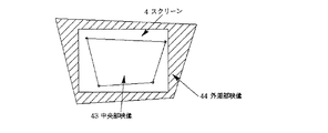
実際の画像歪み補正動作は、その回路構成によって、限界があり、図26に示すような、中央部映像43と外周部映像44を表示し、スクリーン4を中央部映像43を内包し、外周部映像44をはみ出さない形で設置してもらう。この行為は、使用者に対して、暗に画像歪み補正の動作範囲を指示することになり、自動補正を行う際にその回路限界以内での補正動作が行えることとなり、画像歪み補正の動作限界による補正実行が不可能となる事はなくなる。
The actual image distortion correction operation is limited by its circuit configuration, and as shown in FIG. 26, the center image 43 and the outer periphery image 44 are displayed, the
しかしながら、スクリーン4や、スクリーン4の外枠に模様等が表示されていたり、透過型スクリーンの様な場合には、自動でスクリーン4を検出することが難しい。
However, it is difficult to automatically detect the
このような場合に、従来は、全く別の手動補正モードを提供していた(例えば、特許文献1に示されている。)。 In such a case, conventionally, a completely different manual correction mode has been provided (for example, disclosed in Patent Document 1).
本発明の実施の形態では、図27に示すように、上記自動補正時に使用した中央部映像43をそのまま用いて、その4隅をポインタにより指示することで、画像補正を手動で行うことにより、淀みない操作の流れが構築でき、ユーザーは、最小の時間で画像歪み補正操作を実施できる。 In the embodiment of the present invention, as shown in FIG. 27, the center image 43 used at the time of the automatic correction is used as it is, and the four corners are instructed by the pointer, thereby performing the image correction manually, A user-friendly operation flow can be constructed, and the user can perform an image distortion correction operation in a minimum time.
自動調整方法については、第1の実施の形態と同様であり、その後の手動調整動作を説明する。 The automatic adjustment method is the same as that in the first embodiment , and the subsequent manual adjustment operation will be described.
自動調整が失敗に終わった後に、中央部映像43に対して、その4隅にポイント可能な点を明示的に表示するなどして、その部分がポイント可能であることを示唆する。その後、装置に備えられたポインタによって、中央部映像43の4隅をスクリーン4の4隅に合致させることで、表示画面上の位置とスクリーンの4隅が関係付けられ、その後、図25に示される画像歪み補正回路11にて、補正を行うことで補正が可能となる。
After the automatic adjustment is unsuccessful, a point that can be pointed is explicitly displayed at the four corners of the center image 43 to indicate that the part can be pointed. After that, the four corners of the center image 43 are matched with the four corners of the
1 光源(ランプ)
2 表示デバイス(液晶パネル)
3 投射レンズ
4 スクリーン
5 イメージセンサ
6 画像取込部
7 投射表示位置検出部
8、18 スクリーン位置検出部
9 スクリーン歪み検出部
10 映像入力部
11 画像歪み補正回路
12 表示デバイス駆動回路
13 ハーフミラー
14 画像明度データ
15 二値化手段
16 直線検出手段
17 交点検出手段
19 エッジ検出手段
20 直線当てはめ手段
21 イメージセンサ撮像画像
22 プロジェクタ投射表示画面全体画像
23 表示用パターン生成部
24 スクリーン位置画像
25 位置・大きさ補正された表示画像
26 フォーカス検出部
27 レンズフォーカス位置検出部
28 距離検出部補正係数算出部
29 投射表示画面位置−スクリーン位置比較部
30 縮小しない表示範囲
31 縮小した表示範囲
32 光学的歪みによる誤差
33 イメージセンサ光学的歪み補正回路
34 75%全白表示画像
35 50%全白表示画像
36 中心表示画像
37 表示デバイス上の画像
38 検出したプロジェクタ投射表示画面全体範囲
39 38を縮小した表示範囲
40 画像歪み補正データ部
41 投射表示画面全体位置算出部
42 画面上のポインタ制御・表示部
43 中央部映像
44 外周部映像
1 Light source (lamp)
2 Display device (LCD panel)
DESCRIPTION OF SYMBOLS 3
Claims (3)
画像を表示する表示デバイスと、
前記画像を投射する投射レンズと、
前記投射レンズの近傍に配置されたイメージセンサと、
前記表示デバイスに供給する画像信号を変形する画像歪補正回路と、を備え、
前記イメージセンサがスクリーンを撮像し、
前記画像歪補正回路が投射表示画面全体画像と該撮像されたスクリーンとの位置関係に基づいて前記供給画像から生成される投射画像の形状が該スクリーンの領域に合うように前記画像歪補正回路が前記供給画像を変形し、
前記投射レンズが前記表示デバイス上に表示された第1の投射表示位置検出パターンを投射し、
前記イメージセンサが該投射された第1の投射表示位置検出パターンを撮像し、
前記投射レンズが前記表示デバイス上に表示された第2の投射表示位置検出パターンを投射し、
前記イメージセンサが該投射された第2の投射表示位置検出パターンを撮像し、
前記投射表示画面全体画像が該撮像された第1及び第2の投射表示位置検出パターンに基づいて算出され、
前記第1の投射表示位置検出パターンが第1の白色領域を含み、
前記第2の投射表示位置検出パターンが第2の白色領域を含み、
前記第1の白色領域は、前記表示デバイス上で全表示領域を縦横各3/4に縮小した領域であって、全表示領域の中央部に位置し、
前記第2の白色領域は、前記表示デバイス上で全表示領域を縦横各1/2に縮小した領域であって、全表示領域の中央部に位置することを特徴とするプロジェクタ装置。 A projector device,
A display device for displaying images;
A projection lens for projecting the image;
An image sensor disposed in the vicinity of the projection lens;
An image distortion correction circuit that deforms an image signal supplied to the display device,
The image sensor images the screen;
The image distortion correction circuit is configured so that the shape of the projection image generated from the supply image matches the area of the screen based on the positional relationship between the entire image on the projection display screen and the captured screen. Transforming the supply image ,
The projection lens projects a first projection display position detection pattern displayed on the display device;
The image sensor images the projected first projection display position detection pattern,
The projection lens projects a second projection display position detection pattern displayed on the display device;
The image sensor images the projected second projection display position detection pattern,
The entire projection display screen image is calculated based on the captured first and second projection display position detection patterns,
The first projection display position detection pattern includes a first white region;
The second projection display position detection pattern includes a second white region;
The first white region is a region obtained by reducing the entire display region to 3/4 each of the vertical and horizontal directions on the display device, and is located at the center of the entire display region,
The projector device according to claim 1, wherein the second white area is an area obtained by reducing the entire display area to ½ each of the vertical and horizontal directions on the display device, and is located at the center of the entire display area .
画像を表示する表示デバイスと、
前記画像を投射する投射レンズと、
前記投射レンズの近傍に配置されたイメージセンサと、
前記表示デバイスに供給する画像信号を変形する画像歪補正回路と、を備え、
前記イメージセンサがスクリーンを撮像し、
前記画像歪補正回路が投射表示画面全体画像と該撮像されたスクリーンとの位置関係に基づいて前記供給画像から生成される投射画像の形状が該スクリーンの領域に合うように前記画像歪補正回路が前記供給画像を変形し、
前記投射レンズが前記表示デバイス上に表示された第1の投射表示位置検出パターンを投射し、
前記イメージセンサが該投射された第1の投射表示位置検出パターンを撮像し、
前記投射レンズが前記表示デバイス上に表示された第2の投射表示位置検出パターンを投射し、
前記イメージセンサが該投射された第2の投射表示位置検出パターンを撮像し、
前記投射表示画面全体画像が該撮像された第1及び第2の投射表示位置検出パターンに基づいて算出され、
前記第1の投射表示位置検出パターンが第1の白色領域を含み、
前記第2の投射表示位置検出パターンが前記表示デバイスの全表示領域の中心を示すものであることを特徴とするプロジェクタ装置。 A projector device,
A display device for displaying images;
A projection lens for projecting the image;
An image sensor disposed in the vicinity of the projection lens;
An image distortion correction circuit that deforms an image signal supplied to the display device,
The image sensor images the screen;
The image distortion correction circuit is configured so that the shape of the projection image generated from the supply image matches the area of the screen based on the positional relationship between the entire image on the projection display screen and the captured screen. Transforming the supply image,
The projection lens projects a first projection display position detection pattern displayed on the display device;
The image sensor images the projected first projection display position detection pattern,
The projection lens projects a second projection display position detection pattern displayed on the display device;
The image sensor images the projected second projection display position detection pattern,
The entire projection display screen image is calculated based on the captured first and second projection display position detection patterns,
The first projection display position detection pattern includes a first white region;
The projector apparatus, wherein the second projection display position detection pattern indicates a center of an entire display area of the display device.
前記第1の白色領域は、前記表示デバイス上で全表示領域を縦横各3/4に縮小した領域であって、全表示領域の中央部に位置することを特徴とするプロジェクタ装置。 The projector device according to claim 2, wherein
The first white region is a region obtained by reducing the entire display region to 3/4 each of the vertical and horizontal directions on the display device, and is located at the center of the entire display region .
Priority Applications (1)
| Application Number | Priority Date | Filing Date | Title |
|---|---|---|---|
| JP2005165494A JP3996610B2 (en) | 2002-07-23 | 2005-06-06 | Projector apparatus and image distortion correction method thereof |
Applications Claiming Priority (4)
| Application Number | Priority Date | Filing Date | Title |
|---|---|---|---|
| JP2002213797 | 2002-07-23 | ||
| JP2002363539 | 2002-12-16 | ||
| JP2003025874 | 2003-02-03 | ||
| JP2005165494A JP3996610B2 (en) | 2002-07-23 | 2005-06-06 | Projector apparatus and image distortion correction method thereof |
Related Parent Applications (1)
| Application Number | Title | Priority Date | Filing Date |
|---|---|---|---|
| JP2003277567A Division JP2004260785A (en) | 2002-07-23 | 2003-07-22 | Projector with distortion correction function |
Related Child Applications (1)
| Application Number | Title | Priority Date | Filing Date |
|---|---|---|---|
| JP2006093614A Division JP3996617B2 (en) | 2002-07-23 | 2006-03-30 | Projector device with image distortion correction function |
Publications (3)
| Publication Number | Publication Date |
|---|---|
| JP2005318652A JP2005318652A (en) | 2005-11-10 |
| JP2005318652A5 JP2005318652A5 (en) | 2006-06-15 |
| JP3996610B2 true JP3996610B2 (en) | 2007-10-24 |
Family
ID=35445489
Family Applications (1)
| Application Number | Title | Priority Date | Filing Date |
|---|---|---|---|
| JP2005165494A Expired - Fee Related JP3996610B2 (en) | 2002-07-23 | 2005-06-06 | Projector apparatus and image distortion correction method thereof |
Country Status (1)
| Country | Link |
|---|---|
| JP (1) | JP3996610B2 (en) |
Cited By (2)
| Publication number | Priority date | Publication date | Assignee | Title |
|---|---|---|---|---|
| US9551918B2 (en) | 2013-12-04 | 2017-01-24 | Canon Kabushiki Kaisha | Image processing apparatus, image processing method, and computer-readable storage medium |
| JP2022527943A (en) * | 2019-11-11 | 2022-06-07 | チョントゥー ジミー テクノロジー カンパニー リミテッド | Ultra-short focus screen alignment method, equipment, ultra-short focus projection equipment and media |
Families Citing this family (10)
| Publication number | Priority date | Publication date | Assignee | Title |
|---|---|---|---|---|
| JP3996617B2 (en) * | 2002-07-23 | 2007-10-24 | Necディスプレイソリューションズ株式会社 | Projector device with image distortion correction function |
| JP2008015381A (en) * | 2006-07-07 | 2008-01-24 | Matsushita Electric Works Ltd | Video display apparatus, distortion correction processing method for video signal |
| JP5386828B2 (en) * | 2008-01-29 | 2014-01-15 | セイコーエプソン株式会社 | Image projection system and program |
| JP5405047B2 (en) * | 2008-05-09 | 2014-02-05 | 三洋電機株式会社 | Projection display device |
| JP5386894B2 (en) | 2008-09-09 | 2014-01-15 | ソニー株式会社 | Image position recognition device, image position recognition method, program, and correction data setting device for image display device |
| JP5736535B2 (en) * | 2009-07-31 | 2015-06-17 | パナソニックIpマネジメント株式会社 | Projection-type image display device and image adjustment method |
| JPWO2011114420A1 (en) * | 2010-03-15 | 2013-06-27 | Necディスプレイソリューションズ株式会社 | Projection type display device and control method thereof |
| JP2012078490A (en) * | 2010-09-30 | 2012-04-19 | Sanyo Electric Co Ltd | Projection image display device, and image adjusting method |
| JP6510213B2 (en) * | 2014-02-18 | 2019-05-08 | パナソニック インテレクチュアル プロパティ コーポレーション オブ アメリカPanasonic Intellectual Property Corporation of America | Projection system, semiconductor integrated circuit, and image correction method |
| JP7149689B2 (en) * | 2017-05-15 | 2022-10-07 | 株式会社荏原製作所 | Video display system and video display method |
Family Cites Families (8)
| Publication number | Priority date | Publication date | Assignee | Title |
|---|---|---|---|---|
| JP2000241874A (en) * | 1999-02-19 | 2000-09-08 | Nec Corp | Method and device for automatically adjusting screen position for projector |
| JP4507307B2 (en) * | 1999-09-16 | 2010-07-21 | 独立行政法人科学技術振興機構 | Video projection device |
| JP2002006397A (en) * | 2000-06-22 | 2002-01-09 | Sony Corp | Image display device |
| JP4961628B2 (en) * | 2000-08-11 | 2012-06-27 | 日本電気株式会社 | Projected image correction system and method |
| JP3497805B2 (en) * | 2000-08-29 | 2004-02-16 | オリンパス株式会社 | Image projection display device |
| JP2002247614A (en) * | 2001-02-15 | 2002-08-30 | Ricoh Co Ltd | Projector |
| JP3996617B2 (en) * | 2002-07-23 | 2007-10-24 | Necディスプレイソリューションズ株式会社 | Projector device with image distortion correction function |
| JP2004260785A (en) * | 2002-07-23 | 2004-09-16 | Nec Viewtechnology Ltd | Projector with distortion correction function |
-
2005
- 2005-06-06 JP JP2005165494A patent/JP3996610B2/en not_active Expired - Fee Related
Cited By (3)
| Publication number | Priority date | Publication date | Assignee | Title |
|---|---|---|---|---|
| US9551918B2 (en) | 2013-12-04 | 2017-01-24 | Canon Kabushiki Kaisha | Image processing apparatus, image processing method, and computer-readable storage medium |
| JP2022527943A (en) * | 2019-11-11 | 2022-06-07 | チョントゥー ジミー テクノロジー カンパニー リミテッド | Ultra-short focus screen alignment method, equipment, ultra-short focus projection equipment and media |
| JP7263546B2 (en) | 2019-11-11 | 2023-04-24 | チョントゥー ジミー テクノロジー カンパニー リミテッド | ALIGNMENT METHOD AND APPARATUS FOR ULTRA-SHORT-FOCUS SCREEN, ULTRA-SHORT-FOCUS PROJECTION APPARATUS AND MEDIUM |
Also Published As
| Publication number | Publication date |
|---|---|
| JP2005318652A (en) | 2005-11-10 |
Similar Documents
| Publication | Publication Date | Title |
|---|---|---|
| JP3996610B2 (en) | Projector apparatus and image distortion correction method thereof | |
| JP3996617B2 (en) | Projector device with image distortion correction function | |
| JP2004260785A (en) | Projector with distortion correction function | |
| EP1508876B1 (en) | Image projection method and device | |
| EP1385335B1 (en) | Image projector with image-feedback control | |
| US7226173B2 (en) | Projector with a plurality of cameras | |
| US8272748B2 (en) | Projection-type display apparatus and method for performing projection adjustment | |
| US7175285B2 (en) | Projection system that adjusts for keystoning | |
| US8425047B2 (en) | Keystone correction and lens adjustment for projector | |
| JP3960390B2 (en) | Projector with trapezoidal distortion correction device | |
| JP5910157B2 (en) | Image projection device | |
| JP5069038B2 (en) | Rear projection display | |
| EP1638345A1 (en) | Method for calculating display characteristic correction data, program for calculating display characteristic correction data, and device for calculating display characteristic correction data | |
| JP5401940B2 (en) | Projection optical system zoom ratio measurement method, projection image correction method using the zoom ratio measurement method, and projector for executing the correction method | |
| EP1954061A2 (en) | Image processing system, projector, information storage medium and image processing method | |
| JP2000241874A (en) | Method and device for automatically adjusting screen position for projector | |
| KR20020066219A (en) | Imaging system, program used for controlling image data in same system, method for correcting distortion of captured image in same system, and recording medium storing procedures for same method | |
| US20210289182A1 (en) | Method of controlling projector and projector | |
| JP2005004165A (en) | Projector having tilt angle measuring device | |
| JP2005017350A (en) | Projector | |
| JP3730982B2 (en) | projector | |
| JP2003087689A (en) | Image correcting device for projector | |
| JP2005024618A (en) | Projector having tilt angle measuring instrument | |
| JP3742086B2 (en) | Projector having tilt angle measuring device | |
| JP2005070412A (en) | Image projector and its focus adjustment method |
Legal Events
| Date | Code | Title | Description |
|---|---|---|---|
| A521 | Written amendment |
Free format text: JAPANESE INTERMEDIATE CODE: A523 Effective date: 20050729 |
|
| RD03 | Notification of appointment of power of attorney |
Free format text: JAPANESE INTERMEDIATE CODE: A7423 Effective date: 20050729 |
|
| RD04 | Notification of resignation of power of attorney |
Free format text: JAPANESE INTERMEDIATE CODE: A7424 Effective date: 20050729 |
|
| RD04 | Notification of resignation of power of attorney |
Free format text: JAPANESE INTERMEDIATE CODE: A7424 Effective date: 20060217 |
|
| A521 | Written amendment |
Free format text: JAPANESE INTERMEDIATE CODE: A523 Effective date: 20060419 |
|
| A131 | Notification of reasons for refusal |
Free format text: JAPANESE INTERMEDIATE CODE: A131 Effective date: 20061220 |
|
| A521 | Written amendment |
Free format text: JAPANESE INTERMEDIATE CODE: A523 Effective date: 20070209 |
|
| A131 | Notification of reasons for refusal |
Free format text: JAPANESE INTERMEDIATE CODE: A131 Effective date: 20070307 |
|
| A521 | Written amendment |
Free format text: JAPANESE INTERMEDIATE CODE: A523 Effective date: 20070507 |
|
| TRDD | Decision of grant or rejection written | ||
| A01 | Written decision to grant a patent or to grant a registration (utility model) |
Free format text: JAPANESE INTERMEDIATE CODE: A01 Effective date: 20070711 |
|
| A61 | First payment of annual fees (during grant procedure) |
Free format text: JAPANESE INTERMEDIATE CODE: A61 Effective date: 20070802 |
|
| FPAY | Renewal fee payment (event date is renewal date of database) |
Free format text: PAYMENT UNTIL: 20100810 Year of fee payment: 3 |
|
| R150 | Certificate of patent or registration of utility model |
Free format text: JAPANESE INTERMEDIATE CODE: R150 |
|
| FPAY | Renewal fee payment (event date is renewal date of database) |
Free format text: PAYMENT UNTIL: 20100810 Year of fee payment: 3 |
|
| FPAY | Renewal fee payment (event date is renewal date of database) |
Free format text: PAYMENT UNTIL: 20110810 Year of fee payment: 4 |
|
| FPAY | Renewal fee payment (event date is renewal date of database) |
Free format text: PAYMENT UNTIL: 20110810 Year of fee payment: 4 |
|
| FPAY | Renewal fee payment (event date is renewal date of database) |
Free format text: PAYMENT UNTIL: 20120810 Year of fee payment: 5 |
|
| FPAY | Renewal fee payment (event date is renewal date of database) |
Free format text: PAYMENT UNTIL: 20120810 Year of fee payment: 5 |
|
| S531 | Written request for registration of change of domicile |
Free format text: JAPANESE INTERMEDIATE CODE: R313531 |
|
| FPAY | Renewal fee payment (event date is renewal date of database) |
Free format text: PAYMENT UNTIL: 20120810 Year of fee payment: 5 |
|
| R350 | Written notification of registration of transfer |
Free format text: JAPANESE INTERMEDIATE CODE: R350 |
|
| FPAY | Renewal fee payment (event date is renewal date of database) |
Free format text: PAYMENT UNTIL: 20130810 Year of fee payment: 6 |
|
| LAPS | Cancellation because of no payment of annual fees |