JP3991483B2 - Disk drive device - Google Patents
Disk drive device Download PDFInfo
- Publication number
- JP3991483B2 JP3991483B2 JP00345399A JP345399A JP3991483B2 JP 3991483 B2 JP3991483 B2 JP 3991483B2 JP 00345399 A JP00345399 A JP 00345399A JP 345399 A JP345399 A JP 345399A JP 3991483 B2 JP3991483 B2 JP 3991483B2
- Authority
- JP
- Japan
- Prior art keywords
- focus
- objective lens
- signal
- focus jump
- disk
- Prior art date
- Legal status (The legal status is an assumption and is not a legal conclusion. Google has not performed a legal analysis and makes no representation as to the accuracy of the status listed.)
- Expired - Fee Related
Links
Images


Classifications
-
- G—PHYSICS
- G11—INFORMATION STORAGE
- G11B—INFORMATION STORAGE BASED ON RELATIVE MOVEMENT BETWEEN RECORD CARRIER AND TRANSDUCER
- G11B7/00—Recording or reproducing by optical means, e.g. recording using a thermal beam of optical radiation by modifying optical properties or the physical structure, reproducing using an optical beam at lower power by sensing optical properties; Record carriers therefor
- G11B7/08—Disposition or mounting of heads or light sources relatively to record carriers
- G11B7/09—Disposition or mounting of heads or light sources relatively to record carriers with provision for moving the light beam or focus plane for the purpose of maintaining alignment of the light beam relative to the record carrier during transducing operation, e.g. to compensate for surface irregularities of the latter or for track following
-
- G—PHYSICS
- G11—INFORMATION STORAGE
- G11B—INFORMATION STORAGE BASED ON RELATIVE MOVEMENT BETWEEN RECORD CARRIER AND TRANSDUCER
- G11B7/00—Recording or reproducing by optical means, e.g. recording using a thermal beam of optical radiation by modifying optical properties or the physical structure, reproducing using an optical beam at lower power by sensing optical properties; Record carriers therefor
- G11B7/08—Disposition or mounting of heads or light sources relatively to record carriers
- G11B7/085—Disposition or mounting of heads or light sources relatively to record carriers with provision for moving the light beam into, or out of, its operative position or across tracks, otherwise than during the transducing operation, e.g. for adjustment or preliminary positioning or track change or selection
- G11B7/08505—Methods for track change, selection or preliminary positioning by moving the head
- G11B7/08511—Methods for track change, selection or preliminary positioning by moving the head with focus pull-in only
-
- G—PHYSICS
- G11—INFORMATION STORAGE
- G11B—INFORMATION STORAGE BASED ON RELATIVE MOVEMENT BETWEEN RECORD CARRIER AND TRANSDUCER
- G11B7/00—Recording or reproducing by optical means, e.g. recording using a thermal beam of optical radiation by modifying optical properties or the physical structure, reproducing using an optical beam at lower power by sensing optical properties; Record carriers therefor
- G11B2007/0003—Recording, reproducing or erasing systems characterised by the structure or type of the carrier
- G11B2007/0009—Recording, reproducing or erasing systems characterised by the structure or type of the carrier for carriers having data stored in three dimensions, e.g. volume storage
- G11B2007/0013—Recording, reproducing or erasing systems characterised by the structure or type of the carrier for carriers having data stored in three dimensions, e.g. volume storage for carriers having multiple discrete layers
Landscapes
- Optical Recording Or Reproduction (AREA)
- Moving Of The Head For Recording And Reproducing By Optical Means (AREA)
- Rotational Drive Of Disk (AREA)
Description
【0001】
【発明の属する技術分野】
本発明は、層構成となる複数の信号記録面を有する記録媒体に対して、その信号記録面にレーザ光を照射してデータの記録又は再生を行うディスクドライブ装置に関するものである。
【0002】
【従来の技術】
光学ディスク記録媒体としていわゆるCD−ROMのようなCD方式のディスクや、マルチメディア用途に好適なDVD(Digital Versatile Disc/Digital Video Disc)と呼ばれるディスクなどが開発されている。
これらの光ディスクに対応するディスクドライブ装置では、スピンドルモータにより回転されているディスクに対して、光ピックアップからそのディスク上のトラックに対してレーザ光を照射し、その反射光を検出することでデータの読出を行なったり、記録データにより変調されたレーザ光を照射することでデータの記録を行ったりする。
【0003】
レーザ光により記録又は再生動作を行うためには、レーザ光のスポットがディスクの記録面上において合焦状態で保たれなければならず、このためディスクドライブ装置には、レーザ光の出力端である対物レンズをディスクに接離する方向に移動させて合焦状態を制御するフォーカスサーボ機構が搭載されている。このフォーカスサーボ機構としては、通常、対物レンズをディスクに接離する方向に移動させるフォーカスコイル及びディスク半径方向に移動させることのできるトラッキングコイルを有する2軸機構と、ディスクからの反射光情報からフォーカスエラー信号(即ち合焦状態からのずれ量の信号)を生成し、そのフォーカスエラー信号に基づいてフォーカスドライブ信号を生成し、上記2軸機構のフォーカスコイルに印加するフォーカスサーボ回路系から構成されている。
即ちフィードバック制御系としてフォーカスサーボ機構が構成される。
【0004】
また、既によく知られているようにフォーカスエラー信号に基づいて合焦状態に引き込むことのできる範囲は、フォーカスエラー信号としてS字カーブが観測される範囲内という非常に狭い範囲であるため、フォーカスサーボを良好に実行するには、フォーカスサーボループをオンとする際の動作として一般にフォーカスサーチと呼ばれる動作が必要となる。
このフォーカスサーチ動作とは、対物レンズをそのフォーカスストローク範囲内で強制的に移動させるようにフォーカスコイルにフォーカスドライブ信号を印加する。このときフォーカスエラー信号を観測していると、対物レンズの位置がある範囲内にある際に、S字カーブが観測される。そのS字カーブのリニアな領域となるタイミング(もしくはゼロクロスタイミング)でフォーカスサーボをオンとするものである。
【0005】
ところで、ディスクの種類によっては、層構成となる複数の記録面を有するものがある。例えば上記DVDの場合、一般にレイヤ0、レイヤ1と呼ばれる2つの信号記録面が形成されるものがある。
2つの信号記録面を有するDVDの構造を図14に示す。
DVDは、直径12cmのディスクとされており、ディスクの厚みは図14に示すように1.2 mmとされている。
【0006】
このDVDの層構造としては、まずディスク表面108側に、光透過率が高くかつ耐機械的特性或いは耐化学特性を有する透明ポリカーボネイト樹脂、ポリ塩化ビニル樹脂、或いはアクリル樹脂等の透明な合成樹脂材料によるディスク基板(透明層)101が形成される。
ディスク基板101には、一方の主面に成形金型に組み込まれたスタンパによってピットが転写され、第1信号記録面102が形成される。この第1信号記録面102におけるピットは、所定の情報信号に対応してそれぞれ円周方向の長さを異にする符号化された小孔としてディスク基板101に形成され、記録トラックを構成することになる。
さらに第1信号記録面102に対応する第1反射層103を介して、第2信号記録面104及び第2信号記録面104に対応する第2反射層105が形成される。第2信号記録面104も、第1信号記録面102と同様に情報信号に対応したピットが形成されることになる。
第2反射層105の上は接着面106とされ、これを介してダミー板107が接着される。
【0007】
このDVDに対してはディスクドライブ装置からのレーザ光がディスク表面108側から入射され、第1信号記録面102又は第2信号記録面104に記録された情報が、その反射光から検出されることになる。
【0008】
即ち第1反射層103は半透明膜とされ、レーザ光の一定割合を反射させるように形成されている。これによってレーザ光が第1信号記録面102に焦点を当てれば第1反射層103による反射光から第1信号記録面102に記録された信号を読み取ることができ、またレーザ光を第2信号記録面104に焦点をあてさせる際は、そのレーザ光は第1反射層103を通過して第2信号記録面104に焦光され、第2反射層105による反射光から第2信号記録面104に記録された信号を読み取ることができる。
【0009】
【発明が解決しようとする課題】
このような2層構造のDVDのように複数の信号記録面を有するディスクに対しては、上記フォーカスサーボ機構は、それぞれの信号記録面に対してレーザ光を合焦させることが必要になり、換言すれば、一方の信号記録面に対しての合焦状態にある時に、他方の信号記録面への合焦状態へ移行させるための動作、即ちフォーカスジャンプ動作を実行できるようにすることが必要である。
このフォーカスジャンプ動作は、一方の信号記録面で合焦状態にあるときに、フォーカスサーボをオフとして対物レンズを強制的に移動させ、他方の信号記録面に対するフォーカス引込範囲内に到達した時点(S字カーブが観測される時点)でフォーカスサーボをオンとすることで実行される。即ち上記フォーカスサーチに類似した動作となる。
【0010】
このようなフォーカスジャンプを行う場合、ディスクの面振れを考慮して、その振れ加速度よりも大きな加速度で対物レンズを移動させるようにして外乱の影響を低減するようにしている。
しかしながら、面振れの大きいディスクは、ディスクの回転周期内において対物レンズの焦点位置が大きく変位することになる。したがって、面振れの大きいディスクに対してフォーカスジャンプ動作を実行させるには、ディスクの回転速度や面振れ量を考慮した複雑なサーボ制御を行うことが要求される。
【0011】
【課題を解決するための手段】
本発明はこのような問題点を解決するために、層構成となる複数の信号記録面を有する記録媒体に対して、その信号記録面にレーザ光を照射してデータの記録又は再生を行うディスクドライブ装置において、前記レーザ光の出力端となる対物レンズを有するピックアップ手段と、前記対物レンズを記録媒体に接離する方向に移動させることで、記録媒体の信号記録面に対するレーザ光の合焦状態を設定する対物レンズ移動手段と、 前記対物レンズと前記信号記録面の相対距離変動量を示す変動距離情報を検出する変動距離情報検出手段と、前記対物レンズ移動手段に対して現在の信号記録面から他の信号記録面に合焦させるフォーカスジャンプ動作を実行させるフォーカスジャンプ制御手段と、前記記録又は再生を行う場合に前記記録媒体を所要の回転速度で回転させる回転速度制御手段と、を備え、前記フォーカスジャンプ動作を実行する際に、前記回転速度制御手段は前記相対距離変動量に対応した所要の速度で前記記録媒体を回転させるとともに、前記フォーカスジャンプ動作を、前記記録媒体の半径方向に対して前記相対距離変動量が所定値以下の位置で実行させるようにする。
【0012】
さらに、所定の期間内における前記変動距離情報を記憶する変動距離情報記憶手段を備え、前記フォーカスジャンプ動作を実行する際には、前記変動距離情報記憶手段に記憶されている変動距離情報とフォーカスジャンプ動作を実行する制御信号に基づいて前記対物レンズ移動手段の制御を行うようにする。
【0013】
さらに、前記対物レンズ移動手段は、前記対物レンズに対して現在の信号記録面から他の信号記録面に合焦状態を移行させる場合に、前記対物レンズの移動制御を行う制御信号を維持するようにする。
【0014】
さらに、面振れ量の閾値となる所定の値を定め、前記記録媒体の前記変動距離情報と半径位置の関係と該所定の値とに基づいて、それぞれの媒体ごとに異なるフォーカスジャンプ動作を許可する半径方向の位置を定め、前記記録媒体それぞれの半径方向位置に基づいてフォーカスジャンプ動作を行うようにする。
【0015】
本発明によれば、層構成となる複数の信号記録面が形成されるディスクの再生を行う場合において、安定したフォーカスジャンプを実行することができるようになる。
【0016】
【発明の実施の形態】
以下、本発明の実施の形態として光ディスクを記録媒体とするディスクドライブ装置を説明していく。
この例のディスクドライブ装置に装填される光ディスクは、例えばDVDとし、特に図14で説明したように信号記録面が2層構造となっているディスクを考える。もちろん他の種類の光ディスクの場合であっても本発明は適用でき、その特徴的な動作(フォーカスジャンプ時の動作)として複数の信号記録面を有する層構造のディスクに有効なものとなる。
【0017】
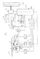
図1は本例のディスクドライブ装置70の要部のブロック図である。
ディスク90は、ターンテーブル7に積載され、再生動作時においてスピンドルモータ6によって一定線速度(CLV)もしくは一定角速度(CAV)で回転駆動される。そしてピックアップ1によってディスク90にエンボスピット形態や相変化ピット形態などで記録されているデータの読み出しが行なわれることになる。
スピンドルモータ6のサーボ制御を実行するために、スピンドルモータ6にはにはそれぞれスピンドルFG(周波数発生器)6aが設けられており、スピンドルモータ6の回転に同期した周波数パルスSFG(以降、FGパルスSFGともいう)を発生させることができるようにされている。システムコントローラ10ではスピンドルFG6aからの周波数パルスSFGに基づいて、スピンドルモータ6の回転情報を検出できるようになる。
【0018】
ピックアップ1内には、レーザ光源となるレーザダイオード4や、反射光を検出するためのフォトディテクタ5、レーザ光の出力端となる対物レンズ2、レーザ光を対物レンズ2を介して信号記録面に照射し、またその反射光をフォトディテクタ5に導く光学系が形成される。
対物レンズ2は二軸機構3によってトラッキング方向及びフォーカス方向に移動可能に保持されている。
またピックアップ1全体はスレッド機構8によりディスク半径方向に移動可能とされている。
【0019】
ディスク90からの反射光情報はフォトディテクタ5によって検出され、受光光量に応じた電気信号とされてRFアンプ9に供給される。
RFアンプ9には、フォトディテクタ5としての複数の受光素子からの出力電流に対応して電流電圧変換回路、マトリクス演算/増幅回路等を備え、マトリクス演算処理により必要な信号を生成する。例えば再生データであるRF信号、サーボ制御のためのフォーカスエラー信号FE、トラッキングエラー信号TEなどを生成する。
RFアンプ9から出力される再生RF信号は2値化回路11へ、フォーカスエラー信号FE、トラッキングエラー信号TEはサーボプロセッサ14へ供給される。
【0020】
RFアンプ9で得られた再生RF信号は2値化回路11で2値化されることでいわゆるEFM+信号(8−16変調信号)とされ、デコーダ12に供給される。デコーダ12ではEFM+復調,エラー訂正処理等を行ない、また必要に応じてMPEGデコードなどを行なってディスク90から読み取られた情報の再生を行なう。
【0021】
なおデコーダ12は、デコードしたデータをデータバッファとしてのキャッシュメモリ20に蓄積していく。
ディスクドライブ装置70からの再生出力としては、キャッシュメモリ20でバファリングされているデータが読み出されて転送出力されることになる。
【0022】
インターフェース部13は、外部のホストコンピュータ80と接続され、ホストコンピュータ80との間で再生データやリードコマンド等の通信を行う。
即ちキャッシュメモリ20に格納された再生データは、インターフェース部13を介してホストコンピュータ80に転送出力される。
またホストコンピュータ80からのリードコマンドその他の信号はインターフェース部13を介してシステムコントローラ10に供給される。
【0023】
サーボプロセッサ14は、RFアンプ9からのフォーカスエラー信号FE、トラッキングエラー信号TEや、デコーダ12もしくはシステムコントローラ10からのスピンドルエラー信号SPE等から、フォーカス、トラッキング、スレッド、スピンドルの各種サーボドライブ信号を生成しサーボ動作を実行させる。
即ちフォーカスエラー信号FE、トラッキングエラー信号TEに応じてフォーカスドライブ信号、トラッキングドライブ信号を生成し、二軸ドライバ16に供給する。二軸ドライバ16はピックアップ1における二軸機構3のフォーカスコイル、トラッキングコイルを駆動することになる。これによってピックアップ1、RFアンプ9、サーボプロセッサ14、二軸ドライバ16、二軸機構3によるトラッキングサーボループ及びフォーカスサーボループが形成される。
【0024】
面振れ検出部30はあとで詳しく説明するように、例えばフォーカスエラー信号FEなどに基づいてディスク90の面振れの検出を行う。
【0025】
なおフォーカスサーボをオンとする際には、まずフォーカスサーチ動作を実行しなければならない。フォーカスサーチ動作とは、フォーカスサーボオフの状態で対物レンズ2を強制的に移動させながらフォーカスエラー信号FEのS字カーブが得られる位置を検出するものである。公知の通り、フォーカスエラー信号のS字カーブのうちのリニア領域は、フォーカスサーボループを閉じることで対物レンズ2の位置を合焦位置に引き込むことのできる範囲である。したがってフォーカスサーチ動作として対物レンズ2を強制的に移動させながら、上記の引込可能な範囲を検出し、そのタイミングでフォーカスサーボをオンとすることで、以降、レーザースポットが合焦状態に保持されるフォーカスサーボ動作が実現されるものである。
【0026】
また本例の場合、ディスク90の信号記録面は、図2(a)(b)に第1信号記録面90a、第2信号記録面90bとして示すように2層構造となっている。即ち、図14で説明した構造となっている。
当然ながら、第1信号記録面90aに対して記録再生を行う場合はレーザ光は第1信号記録面90aに対して合焦状態となっていなければならない。また第2信号記録面90bに対して記録再生を行う場合はレーザ光は第2信号記録面90bに対して合焦状態となっていなければならない。
第1信号記録面90aに対する合焦状態を図2(a)に示すが、このときの対物レンズ2の位置を位置P1であるとする。また第2信号記録面90bに対する合焦状態を図2(b)に示すが、このときの対物レンズ2の位置を位置P2であるとする。なお、位置P0〜P3を対物レンズ2がディスク90に接離する方向に移動可能なフォーカスストローク範囲であるとする。
【0027】
例えば第1信号記録面90aでの再生動作の後に、第2信号記録面90bでの再生動作に移行する場合には、対物レンズ90の位置を位置P1から位置P2に移動させなければならない。もちろん逆の場合もあり得る。
このような第1信号記録面90aと第2信号記録面90bでのフォーカス位置の移動はフォーカスジャンプ動作により行われる。
このフォーカスジャンプ動作は、前述したように、一方の信号記録面で合焦状態にあるときに、フォーカスサーボをオフとして対物レンズ2を強制的に移動させ、他方の信号記録面に対するフォーカス引込範囲内に到達した時点(S字カーブが観測される時点)でフォーカスサーボをオンとすることで実行される。
また、本明細書では、一方の信号記録面から他方の記録面に合焦状態を移行する動作については、対物レンズ2の移動を伴わない動作についてもフォーカスジャンプ動作ということとする。
【0028】
なお図3に、対物レンズ2が位置P0からP3までのフォーカスストローク範囲で移動された場合に観測されるフォーカスエラー信号FEの例を示す。
図示するように第1信号記録面90a及び第2信号記録面90bに対して合焦状態となる位置P1、P2を中心として、それぞれS字カーブが観測される。
各S字カーブのリニア領域の位置範囲が、各信号記録面に対するフォーカス引込可能範囲FW1,FW2となる。
【0029】
図1において、サーボプロセッサ14はさらに、スピンドルモータドライバ17に対してスピンドルエラー信号SPEに応じて生成したスピンドルドライブ信号を供給する。スピンドルモータドライバ17はスピンドルドライブ信号に応じて例えば3相駆動信号をスピンドルモータ6に印加し、スピンドルモータ6のCLV回転を実行させる。またサーボプロセッサ14はシステムコントローラ10からのスピンドルキック/ブレーキ制御信号に応じてスピンドルドライブ信号を発生させ、スピンドルモータドライバ17によるスピンドルモータ6の起動、停止、加速、減速などの動作も実行させる。
【0030】
なお、スピンドルモータ6のCLV回転としての線速度については、システムコントローラ10が各種速度に設定できる。
例えばデコーダ12は、デコード処理に用いるためにEFM信号に同期した再生クロックを生成するが、この再生クロックから現在の回転速度情報を得ることができる。システムコントローラ10もしくはデコーダ12は、このような現在の回転速度情報と、基準速度情報を比較することで、CLVサーボのためのスピンドルエラー信号SPEを生成する。したがって、システムコントローラ11は、基準速度情報としての値を切り換えれば、CLV回転としての線速度を変化させることができる。例えばある通常の線速度を基準として4倍速、8倍速などの線速度を実現できる。
これによりデータ転送レートの高速化が可能となる。
なお、もちろんCAV方式であっても回転速度の切換は可能である。
【0031】
サーボプロセッサ14は、例えばトラッキングエラー信号TEの低域成分として得られるスレッドエラー信号や、システムコントローラ10からのアクセス実行制御などに基づいてスレッドドライブ信号を生成し、スレッドドライバ15に供給する。スレッドドライバ15はスレッドドライブ信号に応じてスレッド機構8を駆動する。スレッド機構8には図示しないが、ピックアップ1を保持するメインシャフト、スレッドモータ、伝達ギア等による機構を有し、スレッドドライバ15がスレッドドライブ信号に応じてスレッドモータ8を駆動することで、ピックアップ1の所要のスライド移動が行なわれる。
【0032】
ピックアップ1におけるレーザダイオード4はレーザドライバ18によってレーザ発光駆動される。
システムコントローラ10はディスク90に対する再生動作を実行させる際に、レーザパワーの制御値をオートパワーコントロール回路19にセットし、オートパワーコントロール回路19はセットされたレーザパワーの値に応じてレーザ出力が行われるようにレーザドライバ18を制御する。
【0033】
なお、記録動作が可能な装置とする場合は、記録データに応じて変調された信号がレーザドライバ18に印加される。
例えば記録可能タイプのディスク90に対して記録を行う際には、ホストコンピュータからインターフェース部13に供給された記録データは図示しないエンコーダによってエラー訂正コードの付加、EFM+変調などの処理が行われた後、レーザドライバ18に供給される。
そしてレーザドライバ18が記録データに応じてレーザ発光動作をレーザダイオード4に実行させることで、ディスク90に対するデータ記録が実行される。
【0034】
以上のようなサーボ及びデコード、エンコードなどの各種動作はマイクロコンピュータによって形成されたシステムコントローラ10により制御される。
そしてシステムコントローラ10は、ホストコンピュータ80からのコマンドに応じて各種処理を実行する。
例えばホストコンピュータ80から、ディスク90に記録されている或るデータの転送を求めるリードコマンドが供給された場合は、まず指示されたアドレスを目的としてシーク動作制御を行う。即ちサーボプロセッサ14に指令を出し、シークコマンドにより指定されたアドレスをターゲットとするピックアップ1のアクセス動作を実行させる。
その後、その指示されたデータ区間のデータをホストコンピュータ80に転送するために必要な動作制御を行う。即ちディスク90からのデータ読出/デコード/バファリング等を行って、要求されたデータを転送する。
なお、ホストコンピュータからのデータ要求がシーケンシャルに行われており、要求されたデータが例えば先読み動作などで予めキャッシュメモリ20に格納されていた場合は、キャッシュヒット転送として、ディスク90からのデータ読出/デコード/バファリング等を行わずに、要求されたデータを転送できる。
【0035】
本例における特徴的な動作となるフォーカスジャンプ動作は、システムコントローラ10の制御に基づいて行われる。
またシステムコントローラ10がフォーカスジャンプシーケンスの制御を行うためにはフォーカスエラー信号FEを監視している必要があり、このためRFアンプ9からのフォーカスエラー信号FEはシステムコントローラ10にも供給されている。
【0036】
なお、フォーカスエラー信号FEにおいてS字カーブが観測されるのは、適切な反射光量がディテクタ5で得られている場合であり、このとき、いわゆる反射光量の和信号としてもレベルが大きくなる。この和信号を所定のスレッショルドレベルと比較した出力は、S字カーブの区間を示すいわゆるFOK信号となるが、システムコントローラ10は、後述する図4の処理において、このFOK信号についても監視するようにすることも考えられる。
図4の処理例ではフォーカスエラー信号FEのゼロクロス検出を行って処理を進めているが、このフォーカスエラー信号のゼロクロスとは、S字カーブ内でのゼロクロスポイントをいう。ところが実際には図3の波形からわかるように反射光が適切に得られないS字カーブ領域以外ではフォーカスエラー信号FEはほぼゼロレベルとなり、対物レンズ移動中に単純にフォーカスエラー信号をゼロレベルとコンパレートしていても正確にS字カーブ領域でのゼロクロスポイントを検出できないことがある。そこで、S字カーブ領域以外のゼロクロスを排除するために、FOK信号をウインドウとしてゼロクロス検出を行うようにすることなどが考えられる。
【0037】
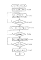
図4、図5によりフォーカスジャンプ時の動作について説明していく。
図4はフォーカスジャンプの際のシステムコントローラ10の処理を、図5はフォーカスジャンプの際のフォーカスエラー信号FE、及びサーボプロセッサ14が二軸ドライバ16に与えるフォーカスドライブ電圧の例を示している。
【0038】
なお図5の波形は、図2(a)の状態から図2(b)の状態に移行するフォーカスジャンプ動作(ディスク90に近づく方向へのフォーカスジャンプ)の場合で示している。
フォーカスジャンプを実行する際には、システムコントローラ10はまず図4のステップF100としてそれまでかけられていたフォーカスサーボをオフとする制御を行う。即ちサーボプロセッサ14にフォーカスサーボループを開くように指示を与える。
【0039】
次に、ステップF101でフォーカスジャンプ方向へのキック電圧VK1を二軸ドライバ16に印加させる。すると図5に示されているt1時点以降は対物レンズ2はディスク90に近づく方向に移動されることになる。
また、t1時点以降は、ステップF101の処理によりキック電圧VK1が印加されることで、対物レンズ2はディスク90に近づく方向に移動して行くが、このときシステムコントローラ10はステップF102で、次にフォーカスエラー信号のゼロクロスが観測されるタイミングを待機している。
このゼロクロスタイミングは、図5のt2時点のタイミングに相当し、つまり対物レンズ2が第1信号記録面90aに対してのS字カーブが観測される位置範囲を脱するタイミングである。
【0040】
このタイミングが検出されたら、システムコントローラ10はステップF103の処理としてフォーカスドライブ電圧をオフとさせる。したがって対物レンズ2はt2時点以降は慣性によりディスク90に近づく方向に移動していく。
この状態でシステムコントローラ10はステップF104で、次のS字カーブが観測され始めるタイミングを待機する。即ち対物レンズ2が移動していくことによって、フォーカスエラー信号FEにはある時点から第2信号記録面90bに対してのS字カーブがみられるようになるが、その開始タイミングを検出するものである。このS字カーブの開始タイミングは、例えばフォーカスエラー信号FEを、ゼロレベルに近い或る所定のレベルと比較していることで検出できる。
【0041】
図5の場合t3時点が、ステップF104でS字カーブの開始と検出されるタイミングであり、この時点からシステムコントローラ10の処理はステップF105に進む。そして、二軸ドライバ16にブレーキ電圧VK2を印加させる。ブレーキ電圧とは、フォーカスジャンプ方向とは逆方向へのキック電圧のことであり、この場合、ディスク90から遠ざかる方向へのキック電圧となる。
ただしブレーキ電圧VK2が印加される時点では対物レンズ2はディスク90に近づく方向に移動している最中であるため、ブレーキ電圧VK2の印加は、対物レンズ2のディスク90に近づく方向への移動速度の低下としてあらわれる。したがってt3時点以降は、対物レンズ2は移動速度は下がっていくが、それまでと同様にディスク90に近づいていく。
【0042】
ここで、ブレーキ電圧VK3が印加されるのは、第2信号記録面90bに対するS字カーブが観測され始めた時点であり、したがってそのまま対物レンズ2の移動が、速度が遅くなりながらも継続されることで、その後の或る時点でフォーカスエラー信号のゼロクロスが検出される。このゼロクロス検出はステップF106の処理となり、図5でいえば時点t4のタイミングとなる。
このゼロクロス検出時前後の対物レンズ2の位置は、図2における位置P2前後に相当し、つまり、第2信号記録面90bに対するフォーカス引込範囲内である。したがって処理をステップF107に進めてフォーカスサーボループをオンとさせることで、第2信号記録面90bに対するフォーカスサーボが良好に引き込まれ、以降フォーカスサーボ動作により第2信号記録面90bに対する合焦状態が維持されることになる。これによって第1信号記録面90aから第2信号記録面90bへのフォーカスジャンプが完了する。
【0043】
本発明では、このようなフォーカスジャンプ動作を行う場合に、ディスク90の面振れに対応して、効率良く安定したジャンプ制御を行うようにしている。
以下、図1に示した面振れ検出部30において行われる面振れの検出方法の一例を説明する。
図6は面振れ検出部30の構成例を説明するブロック図であり、図1に示したシステムコントローラ10とともに示している。
面振れ検出部30に供給されたフォーカスエラー信号FEは、例えばゲインアンプ30a、面振れ周波数に対応したバンドパスフィルタ30bを介してA/D変換器30cによってデジタルデータに変換され、メモリ31に蓄えられるようにされる。
【0044】
メモリ31は、例えばメモリエリア31a、31b、31c・・・として示されているように、スピンドルモータ6の1回転周期に対応してスピンドルFG6aから出力されるFGパルスSFGに対応した記憶領域が形成される。そしてシステムコントローラ10からの制御によって、FGパルスSFGのタイミングに対応したフォーカスエラー信号FEの値が格納されるようにされる。これにより、スピンドルモータ6の一回転、即ち、ディスク90の一回転に対応したフォーカスエラー信号のレベルを得ることができる。
システムコントローラ10では、このようにしてメモリ31の各メモリエリア31(a、b、c・・・)に蓄えられたフォーカスエラー信号を、例えばスピンドルFG6aにおいて一回転の基準とされる所要のFGパルスに基づいて読み出すことにより、読み出されたフォーカスエラー信号のレベルからディスク90の面振れ量を認識することができる。
【0045】
図7は、図6に示した面振れ検出部30により、面振れに対応して検出されるフォーカスエラー信号に基づいて面振れを検出する例を示している。なお、この図に示されている周期T1は、例えばスピンドルモータ6の回転に応じてスピンドルFG6aから出力されるFGパルスSFGに基づいたスピンドルモータ6の1回転周期、即ちディスク90の1回転周期T0の1/2の周期とされる。
面振れ検出部30に対して、例えば図7に示されているようなフォーカスエラー信号FEが入力されると、メモリ31のメモリエリア31(a、b、c・・・)には、例えばFGパルスSFGに対応したタイミングS1〜S11で、A/D変換されたフォーカスエラー信号の値が格納されていく。なお、タイミングS1からS11においてメモリエリア31(a、b、c・・・)に格納されたデータを面振れ情報という。
また、この図にはタイミングS1〜S11として、周期T1における1/2回転周期のみのタイミングを示している。
【0046】
メモリ31には図7に示されているタイミングS1からS11において入力されたフォーカスエラー信号に対応した面振れ情報が格納されることになるが、システムコントローラ10では、メモリ31から読み出した1回転周期T0内の所定期間内(周期T1)の面振れ情報において、最大値のものと最小値のものを検出する。この図に示されている例では最大値としてタイミングS1に対応した面振れ情報Pt、また最小値としてタイミングS11に対応した面振れ情報Pbが検出される。
即ち、これらの面振れ情報Pt、Pbの差が当該ディスク90の面振れ量に相当するレベルとされ、面振れ情報Pt、Pbの差が大きい場合は面振れ量が大きい、同じく面振れ情報Pt、Pbの差が小さいときには面振れ量が小さいとすることができる。
【0047】
このように、ディスク90の1回転周期の所定期間における例えばフォーカスエラー信号FEのレベルを検出することにより、その最大値と最小値から当該ディスクの面振れ量を検出することができるようになる。
なお、本明細書では上記した説明では、フォーカスエラー信号FEに基づい面振れ量を検出する例を挙げたが、フォーカスエラー信号FEに基づいて、例えばサーボプロセッサ14で生成されるフォーカスドライブ信号を用いても、同じように面振れ量の検出を行うことができる。
【0048】
本例ではこのようにして求められた面振れ情報に基づいて、以下に示すようなフォーカスジャンプ動作時における所要の制御を実行する。
(1) フォーカスジャンプ位置の移動
(2) 面振れ情報のフィードフォワード
(3) 対物レンズの位置状態のホールド
(4) 面振れ量に応じた減速
【0049】
(1) フォーカスジャンプ位置の移動
ディスク90における面振れは、ディスク90の外周側に行くにつれて大きなものとなる。即ち、ディスク90の内周側においては比較的面振れが小さいとすることができる。したがって、面振れの小さい内周側でフォーカスジャンプ制御を実行することで、安定した信号記録面の移行を行うことができるようになる。
図8は、ディスク90の半径方向における位置と面振れの関係の一例を模式的に示す図であり、縦軸に面振れ量、横軸にディスク90の中心からの半径位置を示している。半径位置としては、内周側から外周側に向けてr1、r2、r3、r4が示されており、各位置に対応している面振れはディスク90の外周に向かうにつれて大きくなり、外周側に向かうにつれてフォーカスジャンプ動作を安定して行うことが困難になることがわかる。
【0050】
そこで、対物レンズ2がディスク90の外周側位置している場合は、まずシーク動作によって例えば光学ピックアップ1を内周側に移動させる制御を行う。これにより、対物レンズ2はフォーカスジャンプを行う際に面振れの影響が現れない位置に移動することができるようになる。
この場合、面振れ量に対して所要の閾値を設定して、フォーカスジャンプを行う場合、この閾値に基づいてその場で行うか、または内周側に移動した上で行うかという制御を選択的に行うようにする。図8に示す例では、1点鎖線で示されている閾値Sを設定することにより、例えば半径としては位置r2を基準にして、位置r2より外周側ではフォーカスジャンプを行わないようにする。
【0051】
例えばディスク90が「A」として示されている面振れ量と半径位置の関係を有している場合を想定する。この場合、対物レンズ2が位置r2よりも外周側に位置しているときに、例えばホストコンピュータ40からフォーカスジャンプが指示さると、面振れ量が閾値Sよりも小さい位置r2(フォーカスジャンプ許可位置(A))よりも内周側に移動して、フォーカスジャンプを実行するように制御する。なお、実際には、位置r2に対して所要のマージンを考慮した内周側の位置として、位置r2mにおいてフォーカスジャンプが行われるようにする。
また、例えばディスク90が「B」として示されている、「A」よりも面振れの小さいとされている場合を想定する。この場合、例えばホストコンピュータ40からフォーカスジャンプが指示された場合は、面振れ量が閾値Sよりも小さい位置r3(フォーカスジャンプ許可位置(B))よりも内周側に移動して、フォーカスジャンプを実行するように制御すればよい。この場合も、実際には、位置r3に対して所要のマージンを考慮した内周側の位置として、位置r3mにおいてフォーカスジャンプが行われるようにする。
なお、これらの場合の内周側への移動は、例えばスレッド機構8の制御を行うことによって実行される。
【0052】
また、例えばディスクドライブ装置70に対してディスク90が装填された時点で、先に述べた面振れ量の検出方法によって、予めディスク90の所要の半径位置における面振れ量の検出を行って記憶してくようにしてもよい。これにより、現在ディスクドライブ装置に装填されているディスクの面振れ量と半径位置の関係を予め把握しておくことができ、当該ディスクに対してフォーカスジャンプを行う場合、どの半径位置に移動したらよいかを、見極めることができるようになる。即ち、予め記憶されている面振れ量のなかから、フォーカスジャンプが許容されている面振れ量に対応した値を検索することによって、対物レンズ2の移動目的位置を認識することができるようになる。
【0053】
このように、現在対物レンズ2がディスク90の半径位置において例えば外周側とされる面振れが比較的大きい位置にいる場合に、ディスクの面振れ量に対応して光学ピックアップ1を内周側に移動させた後にフォーカスジャンプを行うことによって、面振れの影響を受けず安定したジャンプ動作を行うことができるようになる。
【0054】
(2) 面振れ情報のフィードフォワード
次に、フォーカスジャンプを行う際に面振れ情報(フォーカスエラー信号)をフィードフォワードさせ、面振れに追従させた状態でキック/ブレーキ制御を行う例を説明する。
図9はディスクドライブ装置70にフィードフォワード部40を備えた構成例を示している。この図9において、図1と同一符号は同一部分を示しており説明は省略する。また、RFアンプ9からサーボプロセッサ14に至る信号の経路については、便宜上、トラッキングエラー信号TEとフォーカスエラー信号FEを個々に示している。
フィードフォワード部40はRFアンプ9から出力されるフォーカスエラー信号FEを入力するようにされ、通常の動作時には入力したフォーカスエラー信号FEをそのまま出力し、フォーカスジャンプ時には予めメモリに記憶してある面振れに対応したフォーカスエラー信号を出力するようにされている。このような出力信号の選択制御は例えばシステムコントローラ10によって実行される。
【0055】
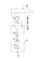
図10はフィードフォワード部40の構成例を機能的なブロック図として示す図である。
この図に示されているスイッチ40aは例えばシステムコントローラ10の制御信号に基づいて切り替え動作が実行され、通常動作時(例えば、再生、記録など)には端子aが選択される。したがって、RFアンプ9から入力したフォーカスエラー信号FEは例えばフィルタ部40bにおいて、A/D変換、周波数帯域制限などが施された後に、スイッチ40aを介してサーボプロセッサ14に供給される。なお、RFアンプ9、サーボプロセッサ14はこの図に示していない。また、バンドパスフィルタ40bを介したフォーカスエラー信号FEはメモリコントローラ40cにも供給され、例えば1周期分(ディスク1回転分)の波形データがメモリ40dに格納される。
【0056】
そして、例えばシステムコントローラ10からの指示に基づいてフォーカスジャンプを実行する場合は、フォーカスジャンプが実行される期間においてスイッチ40aが端子bに切り替えられ、メモリコントローラ40cによってメモリ40dから読み出されたフォーカスエラー信号がサーボプロセッサ14に供給されるようにされる。
メモリ40dに記憶されたフォーカスエラー信号の読み出しを行う場合は、メモリコントローラ40cはディスク90の回転に同期させて、メモリ40dからフォーカスエラー信号FEを読み出して出力する。これは、例えばスピンドルFG6aからのFGパルスに同期した読み出し処理を行うことによって実現される。
これにより、通常動作時にはRFアンプ9からのフォーカスエラー信号FEが出力され、フォーカスジャンプを行う場合には予めメモリ40dに記憶されているフォーカスエラー信号がサーボプロセッサ14に対して出力されるようになる。
【0057】
図11はフィードフォワードされたフォーカスエラー信号に基づいてフォーカスジャンプを行う場合の各種信号の波形を模式的に示す図である。
従来では、フォーカスジャンプを行う場合、フォーカスエラー信号FEは図11(a)に示されているようになる。例えばフォーカスジャンプが行われる直前までの期間(ta〜tc)においては、面振れに追従したうねりを有した波形とされ、フォーカスジャンプが行われる期間(tc〜td)においては対物レンズ2の移動に応じて信号レベルが変化する。そして、フォーカスジャンプが終了すると期間td以降として示されているように、再び面振れに追従したうねりを有した波形となる。なお図11(a)に示すフォーカスエラー信号FEこれは、先に図5(a)に示したフォーカスエラー信号の波形に対応したものとされる。
【0058】
しかし、本例ではフィードフォワード部40を備えることにより、例えば図11(a)の期間ta〜tb間などとして示されるように、ディスク90の1回転に対応した1周期に相当するフォーカスエラー信号を予めメモリ40dに蓄えておく。そして、フォーカスジャンプを行う場合に、フォーカスエラー信号として図11(b)に示されているような信号を出力するようにしている。なお、以降、図11(a)に示されているフォーカスエラー信号をFEa、図11(b)に示されているフォーカスエラー信号をFEbとして説明する。
【0059】
フォーカスエラー信号FEbは、例えば期間ta〜tbに相当するフォーカスエラー信号を予めメモリ40dに記憶し、この記憶した所定期間のフォーカスエラー信号を、例えばシステムコントローラ10からの指示に基づいて、フォーカスジャンプが開始されるタイミングtcを起点として読み出して出力する例として示している。なお、図11(b)では、一例として便宜上フォーカスジャンプを行う直前の信号レベルをフィードフォワードさせる例を示しているが、メモリ40dにフォーカスエラー信号を記憶するタイミングとしては、このようなジャンプ直前に限定されるものではない。
例えば、面振れが半径位置によって異なることは先述したが、このような面振れ差に対応するために、所要の半径位置に移動した場合などに、フォーカスジャンプの実行の有無に関わらず、メモリ40aに対する記憶動作を実行させるようにしてもよい。
【0060】
このようにして、フィードフォワード部40から出力されたフォーカスエラー信号FEbはサーボプロセッサ14に供給される。
また、サーボプロセッサ14に対しては、フォーカスジャンプを実行する場合に、システムコントローラ10から対物レンズ2のフォーカスジャンプ動作を実行させるためのキック/ブレーキパルスが供給される。このキック/ブレーキパルスは、図11(c)に示されているように、フォーカスジャンプが指示されたタイミングtcでシステムコントローラ10からサーボプロセッサ14に供給される。そしてサーボプロセッサ14では、フォーカスエラー信号FEbとキック/ブレーキパルスを加算することによって、フォーカスドライブ信号FDbを生成する。
このフォーカスドライブ信号FDbは、対物レンズ2に対してフォーカスジャンプを実行させつつ、面振れに追従する信号となる。したがって、このようなフォーカスドライブ信号FDbを二軸ドライバ16に供給することにより、面振れに追従しつつ安定したフォーカスジャンプを実行させるように、対物レンズ2を移動させることができるようになる。
【0061】
このように、面振れ情報をフィードフォワードさせるようにした場合、フォーカスジャンプが行われる際にも対物レンズ2は面振れに追従しているので、ディスク90が例えば高速で回転している場合でも安定したジャンプ動作を実行させることができるようになる。
【0062】
(3) 対物レンズの位置状態のホールド
次に、合焦状態とされる信号面の移動を対物レンズ2の移動を行わずに実行する例を説明する。上述した実施の形態では、対物レンズ2自らが合焦状態を得るために、所要の信号記録面に対してフォーカスジャンプ動作を行う例を挙げて説明したが、本例は、対物レンズ2の位置を維持するようにすることで、面振れによってディスク90の信号記録面が合焦位置に対応するのを待機するようにしたものである。なお、本例についても、対物レンズ2の合焦位置が現在の信号記録面から信号記録面に移動することになるので、便宜上フォーカスジャンプ動作という。
また、この例を実現するためのディスクドライブ装置としては図1に示したような構成とされ、フォーカスジャンプを行うタイミングで、サーボプロセッサ14は例えばシステムコントローラ10からの指示に基づいて、フォーカスドライブ信号を所要のレベルに維持することによって実現される。
図12(a)(b)はフォーカスジャンプ時のフォーカスエラー信号とフォーカスドライブ信号の一例を模式的に示す図である。なお、本例においても図11と同じようにフォーカスジャンプは期間tc〜tdにおいて行われるものとして示している。
【0063】
図12(a)に示されているように、フォーカスジャンプが開始されると、フォーカスエラー信号は図11(a)に示した例と同様に、対物レンズ2がディスク90の信号記録面の合焦位置から外れていることを示すレベル変化が現れる。このとき、サーボプロセッサ14では例えばシステムコントローラ10からの指示により、フォーカスエラー信号に基づいたフォーカスドライブ信号を生成しないで、フォーカスジャンプが行われるタイミングtcにおけるフォーカスドライブ信号のレベルを維持するようにする。
したがって、フォーカスジャンプが実行されている期間tc〜tdにおいて、フォーカスドライブ信号は図12(b)に示されているように電圧レベルが維持された信号とされる。そして、フォーカスジャンプが終了したタイミングtd以降、サーボプロセッサ14は再びフォーカスエラー信号に基づいたフォーカスドライブ信号を生成して、フォーカスジャンプ後の信号記録面に対してフォーカスサーボが有効となるようにする。
【0064】
図13(a)(b)は図12(a)(b)に示した期間tc〜tdにおける対物メンズ2とディスク90の信号記録面の位置関係を説明する模式図である。
図13(a)は、例えば第1信号記録面90aにおける合焦状態を示しており、図12(a)におけるタイミングtc以前の状態とされる。この状態で例えばシステムコントローラ10などからフォーカスジャンプの実行が指示されると、対物レンズ2は図12(b)に示したフォーカスドライブ信号によってホールドされ、その位置状態が保持されるようになる。ここで、ディスク90の面振れ量を「M」とした場合、この面振れ量Mによって対物レンズ2に対して信号記録面が近づいて来ることになる。つまり、ディスク90が1回転する間に、対物レンズ2とディスク90の位置関係は、図13(a)乃至図13(b)に示した状態の間で変化するようになる。
したがって、図13(b)が対物レンズ2と第2信号記録面90bが合焦状態となる位置であった場合(ゼロクロス)、この位置でフォーカスの引き込みを開始するようにする。これにより、図13(b)に示されている位置で第2信号記録面90bに対してフォーカスサーボをかけることができるようになる。
【0065】
このように、実施の形態(3)では、フォーカスジャンプを実行する場合、対物レンズ2の位置状態をホールドさせて、ディスク90の面振れによって、目標とされる信号記録面90bが近づいて来るのを待って、フォーカスの引き込みを行うようにしている。つまり、面振れを起こしているディスク90に対して対物レンズ2を移動させないようにしているので、誤って対物レンズ2とディスク90が接触してしまうようなことを回避することができ、安定したフォーカスジャンプを実行することができる。これにより、ディスクドライブ装置70の信頼性を向上することができる。
【0066】
(4) 面振れ量に応じて減速
図1に示した構成とされるディスクドライブ装置では、面振れ検出部30を備えているので、フォーカスジャンプを行う場合に、面振れ検出部30検出された面振れ量に対応してスピンドルモータ6の駆動制御を行い、面振れの影響を受けない回転速度になるまでディスク90の回転速度を減速するようにしてもよい。
即ち、図7に示した面振れ情報Pt、Pbの差が大きい場合は面振れ量が大きいとみなし、比較的低速で回転するようにスピンドルモータ6を制御した状態でフォーカスジャンプを実行する。また面振れ情報Pt、Pbの差が小さいときには面振れ量が小さいとみなし、比較的高速でするようにスピンドルモータ6を制御した状態でフォーカスジャンプを実行する。
これにより、ディスク90の回転状態が、面振れに影響されず安定した状態でフォーカスジャンプを行うことができるようになる。
この場合、単にサーボプロセッサ14によるスピンドルモータ6の駆動制御を行えばよいので、比較的容易に安定したフォーカスジャンプを実行することができるようになる。
【0067】
本発明は、上記実施の形態(1)乃至(4)で説明したようにして、ディスク90の面振れに対応してフォーカスジャンプを行うことにより、現在の信号記録面から他の信号記録面に合焦状態を変移させることができるようになる。したがって、例えばレイヤ0、レイヤ1と呼ばれる2つの信号記録面が形成されるディスクを安定した状態で再生することができるようになる。
【0068】
なお、図7で説明したように、面振れ検出部30において検出されるフォーカスエラー信号FEのピークとされるタイミングは、面振れによる振れ速度がほぼ最小になるとされる。図7で示す例では、面振れ情報Ptと面振れ情報Pbとして示されているタイミングとされる。このタイミングは、面振れ情報のレベルとFGパルスSFGに基づいて判別することが可能とされる。
即ち、ホストコンピュータ80などからフォーカスジャンプを実行する指示を受けた場合、ディスク90の回転周期において面振れ情報Ptまたは面振れ情報Pbに対応したこのタイミングで実際のフォーカスジャンプ動作を実行すればよいことになる。これにより、面振れの影響を抑制し安定した動作のもとで、フォーカスジャンプを実行することができるようになる。
【0069】
【発明の効果】
以上、説明したように本発明のディスクドライブ装置は、フォーカスジャンプ動作を実行する際にディスク(記録媒体)の面振れに対応して、安定したジャンプ動作実行することができる。
【0070】
請求項1のディスクドライブ装置では、フォーカスジャンプを実行する際に、例えばディスクの半径方向に対して、対物レンズとディスクの信号記録面の相対距離変動量とされる面振れ量(フォーカスエラー信号、フォーカスドライブ信号など)が所定値以下の位置に前記対物レンズを移動させるようにしている。したがって、ディスクの回転数を維持した状態でディスクの回転駆動系に不要な負荷をかけずにフォーカスジャンプを行うことができる。
【0071】
また、請求項2のディスクドライブ装置では、ディスクの面振れ量を予め記憶しておき、フォーカスジャンプ動作を実行する際には、記憶されている面振れ量とフォーカスジャンプ動作を実行する制御信号に基づいて前記対物レンズ移動手段の制御を行うようにしている。これにより、ディスクの面振れに追従した状態でフォーカスジャンプを行うことができるようになる。
【0072】
また、請求項3のディスクドライブ装置では、ディスクの或る信号記録面に対する合焦状態から他の信号記録面に対する合焦状態に移行するフォーカスジャンプ動作を実行する際には、対物レンズの移動制御を行う制御信号を維持することにより前記対物レンズの移動を行わないようにしている。これにより、フォーカスジャンプを実行するときに、対物レンズの位置状態は保持されるようになるので、面振れにより他の信号記録面が対物レンズに近づいて来ることにより合焦状態に移行することができるようになる。
【0073】
さらに、請求項4のディスクドライブ装置では、或る信号記録面に対する合焦状態から他の信号記録面に対する合焦状態に移行するフォーカスジャンプ動作を実行する際に、対物レンズとディスクの信号記録面の相対距離変動量が所定値以下となるような速度で前記記録媒体を回転させるようにしている。これにより、面振れの影響を受けずに安定したフォーカスジャンプを行うことができるようになる。
【0074】
このように、本発明は、例えばレイヤ0、レイヤ1と呼ばれる層構成となる複数の信号記録面が形成されるディスクの再生を行う場合において、安定したフォーカスジャンプを実行することができるようになる。
【図面の簡単な説明】
【図1】本発明の実施の形態のディスクドライブ装置のブロック図である。
【図2】実施の形態のフォーカスジャンプ動作の説明図である。
【図3】実施の形態のフォーカスエラー信号のS字カーブの説明図である。
【図4】実施の形態のフォーカスジャンプ動作のフローチャートである。
【図5】実施の形態のフォーカスジャンプ動作の説明図である。
【図6】図1に示す面振れ検出部の構成例を説明するブロック図である。
【図7】面振れ検出部によって面振れ検出を行う場合の例を説明する模式図である。
【図8】面振れ量に対応して所要の半径位置に移動してフォーカスジャンプを行う場合の例を説明する図である。
【図9】本発明のディスクドライブ装置の他の構成例を説明するブロック図である。
【図10】図9に示されているフィードフォワード部の構成例を説明する図である。
【図11】フィードフォワード部を用いた場合の、フォーカスエラー信号及びフォーカスドライブ信号の波形例を説明する図である。
【図12】対物レンズを移動させずに、現在の信号記録面から他の信号記録面に合焦状態を移行させる場合のフォーカスエラー信号及びフォーカスドライブ信号の一例を説明する図である。
【図13】対物レンズを移動させずに、現在の信号記録面から他の信号記録面に合焦状態を移行させる場合の、対物レンズとディスクの信号記録面の位置関係を説明する模式図である。
【図14】DVDの層構造の説明図である。
【符号の説明】
1 ピックアップ、2 対物レンズ、3 二軸機構、4 レーザダイオード、5 フォトディテクタ、6 スピンドルモータ、8 スレッド機構、9 RFアンプ、10 システムコントローラ、13 インターフェース部、14 サーボプロセッサ、20 キャッシュメモリ、30 面振れ検出部、40 フィードフォワード部、70 ディスクドライブ装置、80 ホストコンピュータ、90 ディスク、[0001]
BACKGROUND OF THE INVENTION
The present invention relates to a disk drive apparatus that records or reproduces data by irradiating a laser beam onto a recording medium having a plurality of signal recording surfaces having a layer structure.
[0002]
[Prior art]
As an optical disc recording medium, a CD disc such as a so-called CD-ROM, a disc called DVD (Digital Versatile Disc / Digital Video Disc) suitable for multimedia use, and the like have been developed.
In a disk drive device corresponding to these optical disks, a disk rotated by a spindle motor is irradiated with laser light from an optical pickup to a track on the disk, and the reflected light is detected to detect data. Reading is performed, or data is recorded by irradiating a laser beam modulated by the recording data.
[0003]
In order to perform a recording or reproducing operation with a laser beam, the spot of the laser beam must be kept in focus on the recording surface of the disk. For this reason, the disk drive device has an output end of the laser beam. A focus servo mechanism is mounted to control the in-focus state by moving the objective lens in the direction of moving toward and away from the disk. As this focus servo mechanism, there is usually a biaxial mechanism having a focus coil that moves the objective lens in the direction of contact with and away from the disk and a tracking coil that can be moved in the radial direction of the disk, and focus from the reflected light information from the disk. It is composed of a focus servo circuit system that generates an error signal (that is, a signal of a deviation amount from the in-focus state), generates a focus drive signal based on the focus error signal, and applies it to the focus coil of the biaxial mechanism. Yes.
That is, a focus servo mechanism is configured as a feedback control system.
[0004]
Further, as is well known, the range that can be brought into the in-focus state based on the focus error signal is a very narrow range in which the S-curve is observed as the focus error signal. In order to execute the servo satisfactorily, an operation called a focus search is generally required as an operation for turning on the focus servo loop.
In this focus search operation, a focus drive signal is applied to the focus coil so as to forcibly move the objective lens within the focus stroke range. If the focus error signal is observed at this time, an S-shaped curve is observed when the position of the objective lens is within a certain range. The focus servo is turned on at the timing (or zero cross timing) at which the S-shaped curve becomes a linear region.
[0005]
By the way, some discs have a plurality of recording surfaces in a layer structure. For example, in the case of the above-mentioned DVD, there are those in which two signal recording surfaces generally called layer 0 and
The structure of a DVD having two signal recording surfaces is shown in FIG.
The DVD is a disk having a diameter of 12 cm, and the thickness of the disk is 1.2 mm as shown in FIG.
[0006]
As the layer structure of this DVD, first, a transparent synthetic resin material such as transparent polycarbonate resin, polyvinyl chloride resin, or acrylic resin having high light transmittance and mechanical or chemical resistance on the disk surface 108 side. Thus, a disk substrate (transparent layer) 101 is formed.
On the
Further, the second signal recording surface 104 and the second reflection layer 105 corresponding to the second signal recording surface 104 are formed via the first reflection layer 103 corresponding to the first signal recording surface 102. Similarly to the first signal recording surface 102, the second signal recording surface 104 is formed with pits corresponding to the information signal.
The second reflection layer 105 has an adhesive surface 106 on which the dummy plate 107 is bonded.
[0007]
Laser light from the disk drive device is incident on the DVD from the disk surface 108 side, and information recorded on the first signal recording surface 102 or the second signal recording surface 104 is detected from the reflected light. become.
[0008]
That is, the first reflective layer 103 is a translucent film and is formed so as to reflect a certain ratio of the laser light. As a result, when the laser beam is focused on the first signal recording surface 102, the signal recorded on the first signal recording surface 102 can be read from the reflected light from the first reflective layer 103, and the laser beam can be read by the second signal recording surface. When focusing on the surface 104, the laser light passes through the first reflective layer 103 and is focused on the second signal recording surface 104, and the reflected light from the second reflective layer 105 is applied to the second signal recording surface 104. The recorded signal can be read.
[0009]
[Problems to be solved by the invention]
For a disc having a plurality of signal recording surfaces such as a DVD having such a two-layer structure, the focus servo mechanism needs to focus laser light on each signal recording surface. In other words, it is necessary to be able to execute an operation for shifting to the focused state on the other signal recording surface, that is, the focus jump operation, when the focused state is on the one signal recording surface. It is.
This focus jump operation is performed when the focus servo is turned off and the objective lens is forcibly moved when the one signal recording surface is in focus, and reaches the focus pull-in range with respect to the other signal recording surface (S This is executed by turning on the focus servo at the time when the character curve is observed. That is, the operation is similar to the focus search.
[0010]
When performing such a focus jump, the influence of disturbance is reduced by moving the objective lens at an acceleration larger than the shake acceleration in consideration of the surface shake of the disc.
However, in the case of a disc having a large surface deflection, the focal position of the objective lens is greatly displaced within the disc rotation period. Therefore, in order to execute a focus jump operation on a disk with large surface runout, it is required to perform complicated servo control in consideration of the rotational speed of the disc and the surface runout amount.
[0011]
[Means for Solving the Problems]
In order to solve such a problem, the present invention is a disk which records or reproduces data by irradiating a laser beam onto a recording medium having a plurality of signal recording surfaces having a layer structure. In the drive device, the pickup means having an objective lens serving as an output end of the laser light and the focus state of the laser light with respect to the signal recording surface of the recording medium by moving the objective lens in the direction of contact with and away from the recording medium An objective lens moving means for setting, a variable distance information detecting means for detecting variable distance information indicating a relative distance fluctuation amount between the objective lens and the signal recording surface, and a current signal recording surface with respect to the objective lens moving means Focus jump control means for executing a focus jump operation for focusing on the other signal recording surface from Rotation speed control means for rotating the recording medium at a required rotation speed when performing the recording or reproduction; With When executing the focus jump operation, the rotation speed control means rotates the recording medium at a required speed corresponding to the relative distance fluctuation amount, and The focus jump operation is executed at a position where the relative distance fluctuation amount is a predetermined value or less with respect to the radial direction of the recording medium.
[0012]
Furthermore, the apparatus includes a variable distance information storage unit that stores the variable distance information within a predetermined period, and when executing the focus jump operation, the variable distance information and the focus jump stored in the variable distance information storage unit The objective lens moving means is controlled based on a control signal for executing the operation. Like that.
[0013]
Further, the objective lens moving means sends a control signal for controlling the movement of the objective lens when the focus state is shifted from the current signal recording surface to another signal recording surface with respect to the objective lens. To maintain.
[0014]
Further, a predetermined value as a threshold value of the surface shake amount is set, and a different focus jump operation is permitted for each medium based on the relationship between the variable distance information and the radial position of the recording medium and the predetermined value. A radial position is determined, and a focus jump operation is performed based on the radial position of each recording medium. Like that.
[0015]
According to the present invention, a stable focus jump can be performed when a disc on which a plurality of signal recording surfaces having a layer structure is formed is reproduced.
[0016]
DETAILED DESCRIPTION OF THE INVENTION
Hereinafter, a disk drive apparatus using an optical disk as a recording medium will be described as an embodiment of the present invention.
An optical disk loaded in the disk drive apparatus of this example is a DVD, for example, and a disk having a signal recording surface having a two-layer structure as described with reference to FIG. 14 is considered. Of course, the present invention can be applied to other types of optical discs, and is effective for a layered disc having a plurality of signal recording surfaces as its characteristic operation (operation during focus jump).
[0017]
FIG. 1 is a block diagram of the main part of the
The
In order to execute servo control of the
[0018]
In the
The
The
[0019]
Reflected light information from the
The
The reproduction RF signal output from the
[0020]
The reproduced RF signal obtained by the
[0021]
The
As playback output from the
[0022]
The
That is, the reproduction data stored in the
A read command and other signals from the
[0023]
The
That is, a focus drive signal and a tracking drive signal are generated according to the focus error signal FE and the tracking error signal TE and supplied to the biaxial driver 16. The biaxial driver 16 drives the focus coil and tracking coil of the
[0024]
As will be described in detail later, the surface
[0025]
When the focus servo is turned on, a focus search operation must first be executed. The focus search operation is to detect a position where the S-shaped curve of the focus error signal FE is obtained while forcibly moving the
[0026]
In the case of this example, the signal recording surface of the
Naturally, when recording / reproducing is performed on the first signal recording surface 90a, the laser beam must be in focus with respect to the first signal recording surface 90a. Further, when recording / reproducing is performed on the second
FIG. 2A shows the in-focus state with respect to the first signal recording surface 90a, and the position of the
[0027]
For example, when shifting to the reproducing operation on the second
Such movement of the focus position on the first signal recording surface 90a and the second
As described above, this focus jump operation is performed by forcibly moving the
Further, in this specification, an operation that shifts the in-focus state from one signal recording surface to the other recording surface is an operation that does not involve the movement of the
[0028]
FIG. 3 shows an example of the focus error signal FE observed when the
As shown in the figure, S-shaped curves are observed around positions P1 and P2 that are in focus with respect to the first signal recording surface 90a and the second
The position range of the linear region of each S-shaped curve is the focus retractable range FW1, FW2 for each signal recording surface.
[0029]
In FIG. 1, the
[0030]
Note that the
For example, the
As a result, the data transfer rate can be increased.
Of course, the rotation speed can be switched even in the CAV system.
[0031]
The
[0032]
The
When the
[0033]
In the case of an apparatus capable of recording operation, a signal modulated according to recording data is applied to the
For example, when recording is performed on a
The
[0034]
Various operations such as servo, decoding, and encoding as described above are controlled by a
The
For example, when a read command requesting transfer of certain data recorded on the
Thereafter, operation control necessary for transferring the data in the designated data section to the
If data requests from the host computer are made sequentially and the requested data is stored in the
[0035]
The focus jump operation, which is a characteristic operation in this example, is performed based on the control of the
Further, in order for the
[0036]
Note that the S-shaped curve is observed in the focus error signal FE when an appropriate amount of reflected light is obtained by the
In the processing example of FIG. 4, the zero error detection of the focus error signal FE is performed and the process proceeds. The focus error signal zero cross refers to a zero cross point in the S-curve. However, as can be seen from the waveform of FIG. 3, the focus error signal FE is almost zero level except in the S-curve area where the reflected light cannot be obtained appropriately, and the focus error signal is simply set to zero level while the objective lens is moving. Even if they are compared, the zero cross point in the S-curve area may not be detected accurately. Therefore, in order to eliminate the zero crossing other than the S-curve region, it may be possible to perform the zero cross detection using the FOK signal as a window.
[0037]
The operation at the time of focus jump will be described with reference to FIGS.
FIG. 4 shows processing of the
[0038]
The waveform of FIG. 5 is shown in the case of a focus jump operation (focus jump in a direction approaching the disk 90) that shifts from the state of FIG. 2A to the state of FIG. 2B.
When executing the focus jump, the
[0039]
Next, a kick voltage VK1 in the focus jump direction is applied to the biaxial driver 16 in step F101. Then, after the time t1 shown in FIG. 5, the
Further, after the time t1, the
This zero cross timing corresponds to the timing at time t2 in FIG. 5, that is, the timing at which the
[0040]
When this timing is detected, the
In this state, the
[0041]
In FIG. 5, the time point t3 is the timing at which the start of the S-curve is detected in step F104. From this point, the process of the
However, since the
[0042]
Here, the brake voltage VK3 is applied when the S-shaped curve with respect to the second
The position of the
[0043]
In the present invention, when such a focus jump operation is performed, an efficient and stable jump control is performed corresponding to the surface shake of the
Hereinafter, an example of a method of detecting the surface shake performed in the surface
FIG. 6 is a block diagram illustrating a configuration example of the surface
The focus error signal FE supplied to the surface
[0044]
In the
In the
[0045]
FIG. 7 shows an example in which the surface shake is detected by the surface
When the focus error signal FE as shown in FIG. 7 is input to the surface
Further, in this drawing, as the timings S1 to S11, the timing of only the 1/2 rotation cycle in the cycle T1 is shown.
[0046]
The surface vibration information corresponding to the focus error signal input at the timings S1 to S11 shown in FIG. 7 is stored in the
That is, the difference between the surface shake information Pt and Pb is set to a level corresponding to the surface shake amount of the
[0047]
Thus, by detecting, for example, the level of the focus error signal FE in a predetermined period of one rotation cycle of the
In the present specification, in the above description, an example in which the surface shake amount is detected based on the focus error signal FE has been described. However, based on the focus error signal FE, for example, a focus drive signal generated by the
[0048]
In this example, the required control at the time of the focus jump operation as described below is executed based on the surface shake information thus obtained.
(1) Move the focus jump position
(2) Feed forward of surface runout information
(3) Hold the objective lens position
(4) Deceleration according to surface runout
[0049]
(1) Move the focus jump position
The surface runout in the
FIG. 8 is a diagram schematically showing an example of the relationship between the position of the
[0050]
Therefore, when the
In this case, when performing a focus jump by setting a required threshold value for the surface runout amount, a control is selectively performed based on this threshold value, either on the spot or after moving to the inner circumference side. To do. In the example shown in FIG. 8, by setting a threshold value S indicated by a one-dot chain line, for example, the radius is the position r2, and the focus jump is not performed on the outer peripheral side from the position r2.
[0051]
For example, it is assumed that the
Further, for example, a case is assumed in which the
In addition, the movement to the inner peripheral side in these cases is executed by controlling the thread mechanism 8, for example.
[0052]
Further, for example, when the
[0053]
In this way, when the
[0054]
(2) Feed forward of surface runout information
Next, an example will be described in which kick / brake control is performed in a state in which surface shake information (focus error signal) is feed-forwarded when the focus jump is performed and the surface shake is followed.
FIG. 9 shows a configuration example in which the
The
[0055]
FIG. 10 is a diagram illustrating a configuration example of the
The
[0056]
For example, when a focus jump is executed based on an instruction from the
When reading the focus error signal stored in the
As a result, the focus error signal FE is output from the
[0057]
FIG. 11 is a diagram schematically showing waveforms of various signals when a focus jump is performed based on a feed-forward focus error signal.
Conventionally, when a focus jump is performed, the focus error signal FE is as shown in FIG. For example, in the period (ta to tc) immediately before the focus jump is performed, the waveform has a wave following the surface shake, and in the period (tc to td) in which the focus jump is performed, the
[0058]
However, in this example, by providing the
[0059]
As the focus error signal FEb, for example, a focus error signal corresponding to the period ta to tb is stored in the
For example, as described above, the surface shake varies depending on the radial position. However, in order to cope with such a surface shake difference, the
[0060]
In this way, the focus error signal FEb output from the
The
The focus drive signal FDb is a signal that follows the surface shake while causing the
[0061]
Thus, when the surface shake information is fed forward, the
[0062]
(3) Hold the objective lens position
Next, an example in which the movement of the signal surface that is brought into focus is performed without moving the
Further, the disk drive device for realizing this example is configured as shown in FIG. 1, and at the timing of performing the focus jump, the
12A and 12B are diagrams schematically showing an example of a focus error signal and a focus drive signal at the time of focus jump. In this example as well, the focus jump is shown as being performed in the period tc to td, as in FIG.
[0063]
As shown in FIG. 12A, when the focus jump is started, the focus error signal is generated when the
Therefore, in the period tc to td during which the focus jump is executed, the focus drive signal is a signal whose voltage level is maintained as shown in FIG. Then, after the timing td when the focus jump is completed, the
[0064]
FIGS. 13A and 13B are schematic diagrams for explaining the positional relationship between the objective men's 2 and the signal recording surface of the
FIG. 13A shows, for example, a focused state on the first signal recording surface 90a, which is a state before the timing tc in FIG. In this state, for example, when execution of a focus jump is instructed from the
Accordingly, when FIG. 13B shows a position where the
[0065]
As described above, in the embodiment (3), when the focus jump is executed, the target state of the
[0066]
(4) Decelerate according to surface runout
Since the disk drive apparatus having the configuration shown in FIG. 1 includes the surface
That is, when the difference between the surface shake information Pt and Pb shown in FIG. 7 is large, it is considered that the surface shake amount is large, and the focus jump is executed in a state where the
As a result, the focus jump can be performed in a state where the rotation state of the
In this case, since the drive control of the
[0067]
In the present invention, as described in the above embodiments (1) to (4), the focus jump is performed in response to the surface shake of the
[0068]
As described with reference to FIG. 7, the timing at which the focus error signal FE detected by the surface
That is, when an instruction to execute a focus jump is received from the
[0069]
【The invention's effect】
As described above, the disc drive apparatus of the present invention can execute a stable jump operation corresponding to the surface shake of the disc (recording medium) when executing the focus jump operation.
[0070]
In the disk drive device according to
[0071]
In the disk drive device according to the second aspect of the present invention, the surface shake amount of the disk is stored in advance, and when executing the focus jump operation, the stored surface shake amount and the control signal for executing the focus jump operation are used. Based on this, the objective lens moving means is controlled. As a result, the focus jump can be performed in a state in which the surface vibration of the disk follows.
[0072]
Further, in the disk drive device according to
[0073]
Furthermore, in the disk drive device according to
[0074]
As described above, the present invention can perform a stable focus jump when reproducing a disc on which a plurality of signal recording surfaces having a layer structure called, for example, layer 0 or
[Brief description of the drawings]
FIG. 1 is a block diagram of a disk drive device according to an embodiment of the present invention.
FIG. 2 is an explanatory diagram of a focus jump operation according to the embodiment.
FIG. 3 is an explanatory diagram of an S-shaped curve of a focus error signal according to the embodiment.
FIG. 4 is a flowchart of a focus jump operation according to the embodiment.
FIG. 5 is an explanatory diagram of a focus jump operation according to the embodiment.
6 is a block diagram illustrating a configuration example of a surface shake detection unit illustrated in FIG. 1. FIG.
FIG. 7 is a schematic diagram illustrating an example of a case where surface shake detection is performed by a surface shake detection unit.
FIG. 8 is a diagram illustrating an example of a case where a focus jump is performed by moving to a required radial position corresponding to a surface shake amount.
FIG. 9 is a block diagram illustrating another configuration example of the disk drive device of the present invention.
10 is a diagram for explaining a configuration example of a feedforward unit shown in FIG. 9;
FIG. 11 is a diagram for explaining an example of waveforms of a focus error signal and a focus drive signal when a feedforward unit is used.
FIG. 12 is a diagram for explaining an example of a focus error signal and a focus drive signal in a case where a focus state is shifted from the current signal recording surface to another signal recording surface without moving the objective lens.
FIG. 13 is a schematic diagram for explaining the positional relationship between the objective lens and the signal recording surface of the disc when the focus state is shifted from the current signal recording surface to another signal recording surface without moving the objective lens. is there.
FIG. 14 is an explanatory diagram of a layer structure of a DVD.
[Explanation of symbols]
1 Pickup, 2 Objective lens, 3 Biaxial mechanism, 4 Laser diode, 5 Photo detector, 6 Spindle motor, 8 Thread mechanism, 9 RF amplifier, 10 System controller, 13 Interface unit, 14 Servo processor, 20 Cache memory, 30 Surface deflection Detection unit, 40 feedforward unit, 70 disk drive device, 80 host computer, 90 disk,
Claims (4)
前記レーザ光の出力端となる対物レンズを有するピックアップ手段と、
前記対物レンズを記録媒体に接離する方向に移動させることで、記録媒体の信号記録面に対するレーザ光の合焦状態を設定する対物レンズ移動手段と、
前記対物レンズと前記信号記録面の相対距離変動量を示す変動距離情報を検出する変動距離情報検出手段と、
前記対物レンズ移動手段に対して現在の信号記録面から他の信号記録面に合焦させるフォーカスジャンプ動作を実行させるフォーカスジャンプ制御手段と、
前記記録又は再生を行う場合に前記記録媒体を所要の回転速度で回転させる回転速度制御手段と、
を備え、
前記フォーカスジャンプ動作を実行する際に、前記回転速度制御手段は前記相対距離変動量に対応した所要の速度で前記記録媒体を回転させるとともに、
前記フォーカスジャンプ動作を、前記記録媒体の半径方向に対して前記相対距離変動量が所定値以下の位置で実行させるようにしたこと
を特徴とするディスクドライブ装置。In a disk drive device that records or reproduces data by irradiating a laser beam onto a recording medium having a plurality of signal recording surfaces in a layer configuration.
Pickup means having an objective lens serving as an output end of the laser beam;
An objective lens moving means for setting the focused state of the laser beam with respect to the signal recording surface of the recording medium by moving the objective lens in a direction in contact with and away from the recording medium;
Fluctuation distance information detecting means for detecting fluctuation distance information indicating a relative distance fluctuation amount between the objective lens and the signal recording surface;
A focus jump control means for executing a focus jump operation for focusing the objective lens moving means from the current signal recording surface to another signal recording surface;
A rotation speed control means for rotating the recording medium at a required rotation speed when performing the recording or reproduction;
With
When executing the focus jump operation, the rotation speed control means rotates the recording medium at a required speed corresponding to the relative distance fluctuation amount, and
The disk drive apparatus according to claim 1, wherein the focus jump operation is executed at a position where the relative distance fluctuation amount is a predetermined value or less with respect to a radial direction of the recording medium.
前記フォーカスジャンプ動作を実行する際には、前記変動距離情報記憶手段に記憶されている変動距離情報とフォーカスジャンプ動作を実行する制御信号に基づいて前記対物レンズ移動手段の制御を行うようにしたこと
を特徴とする請求項1に記載のディスクドライブ装置。A variable distance information storage means for storing the variable distance information within a predetermined period;
When executing the focus jump operation, the objective lens moving unit is controlled based on the variable distance information stored in the variable distance information storage unit and a control signal for executing the focus jump operation. The disk drive device according to claim 1 .
前記記録媒体それぞれの半径方向位置に基づいてフォーカスジャンプ動作を行うようにしたことを特徴とする請求項1乃至3に記載のディスクドライブ装置。 Radial direction that determines a predetermined value as a threshold value of the surface shake amount, and allows different focus jump operations for each medium based on the relationship between the variable distance information and the radial position of the recording medium and the predetermined value The position of
4. The disk drive device according to claim 1, wherein a focus jump operation is performed based on a radial position of each of the recording media .
Priority Applications (6)
| Application Number | Priority Date | Filing Date | Title |
|---|---|---|---|
| JP00345399A JP3991483B2 (en) | 1999-01-08 | 1999-01-08 | Disk drive device |
| TW088123415A TW455863B (en) | 1999-01-08 | 1999-12-31 | Disc drive |
| US09/477,209 US6552971B2 (en) | 1999-01-08 | 2000-01-04 | Disk drive apparatus for a recording medium having plural recording surfaces in a layered structure |
| MYPI20000058 MY125323A (en) | 1999-01-08 | 2000-01-06 | Disk drive apparatus for a recording medium having plural recording surfaces in a layered structure |
| CNB00100932XA CN1162843C (en) | 1999-01-08 | 2000-01-07 | Disk-driving apparatus |
| KR1020000000764A KR100695356B1 (en) | 1999-01-08 | 2000-01-08 | Disk drive device |
Applications Claiming Priority (1)
| Application Number | Priority Date | Filing Date | Title |
|---|---|---|---|
| JP00345399A JP3991483B2 (en) | 1999-01-08 | 1999-01-08 | Disk drive device |
Publications (3)
| Publication Number | Publication Date |
|---|---|
| JP2000207750A JP2000207750A (en) | 2000-07-28 |
| JP2000207750A5 JP2000207750A5 (en) | 2006-02-16 |
| JP3991483B2 true JP3991483B2 (en) | 2007-10-17 |
Family
ID=11557758
Family Applications (1)
| Application Number | Title | Priority Date | Filing Date |
|---|---|---|---|
| JP00345399A Expired - Fee Related JP3991483B2 (en) | 1999-01-08 | 1999-01-08 | Disk drive device |
Country Status (6)
| Country | Link |
|---|---|
| US (1) | US6552971B2 (en) |
| JP (1) | JP3991483B2 (en) |
| KR (1) | KR100695356B1 (en) |
| CN (1) | CN1162843C (en) |
| MY (1) | MY125323A (en) |
| TW (1) | TW455863B (en) |
Families Citing this family (27)
| Publication number | Priority date | Publication date | Assignee | Title |
|---|---|---|---|---|
| US6511184B2 (en) | 2000-04-05 | 2003-01-28 | Matsushita Electric Industrial Co., Ltd. | Color image display apparatus |
| JP2001307341A (en) | 2000-04-24 | 2001-11-02 | Matsushita Electric Ind Co Ltd | Optical disk device |
| US6568811B2 (en) | 2000-06-12 | 2003-05-27 | Matsushita Electric Industrial Co., Ltd. | Color image display device and projection-type image display apparatus |
| JP2001356286A (en) | 2000-06-12 | 2001-12-26 | Matsushita Electric Ind Co Ltd | Projection type image display device |
| US7268794B2 (en) * | 2000-10-30 | 2007-09-11 | Yamaha Corporation | Method of printing label on optical disk, optical disk unit, and optical disk |
| JP3517223B2 (en) | 2001-04-24 | 2004-04-12 | 株式会社東芝 | Optical disk apparatus and optical disk processing method |
| TW509930B (en) * | 2001-10-19 | 2002-11-11 | Acer Labs Inc | Layer-jumping control device and method of optical disk driver |
| JP3956756B2 (en) * | 2001-10-31 | 2007-08-08 | ヤマハ株式会社 | Optical disk recording device |
| JP3772136B2 (en) | 2002-07-30 | 2006-05-10 | 株式会社東芝 | Optical disk device and access method of optical disk device |
| US20040047617A1 (en) * | 2002-08-21 | 2004-03-11 | Matos Jose R. | Disc player system |
| JP4633346B2 (en) * | 2003-05-12 | 2011-02-16 | ソニー株式会社 | Recording medium, recording apparatus, and recording method |
| JP4429086B2 (en) * | 2004-03-09 | 2010-03-10 | 三洋電機株式会社 | Optical disc recording / reproducing apparatus and optical disc evaluation method |
| JP3992044B2 (en) * | 2004-04-22 | 2007-10-17 | ソニー株式会社 | Playback device, focus jump method |
| US7336569B2 (en) * | 2004-06-03 | 2008-02-26 | Dcard, Inc. | Optical disk tracking servo circuit enabled to compensate for non-continuous track segments or prolonged defect |
| RU2348083C1 (en) * | 2004-10-25 | 2009-02-27 | Мацусита Электрик Индастриал Ко., Лтд. | Device for optical disk |
| KR100675456B1 (en) | 2005-01-06 | 2007-01-26 | 주식회사 히타치엘지 데이터 스토리지 코리아 | Apparatus and method for searching a target position on multi layer disc |
| JP4469375B2 (en) | 2005-01-18 | 2010-05-26 | 富士通株式会社 | Information reproducing apparatus and surface runout measuring method |
| JP3971427B2 (en) * | 2005-03-02 | 2007-09-05 | 株式会社ソニー・コンピュータエンタテインメント | Optical disc drive apparatus, optical disc drive apparatus control method, and control program |
| JP2007102864A (en) * | 2005-09-30 | 2007-04-19 | Toshiba Samsung Storage Technology Corp | Optical disk device and method for controlling focus of optical disk device |
| JP4492551B2 (en) * | 2006-01-30 | 2010-06-30 | パナソニック株式会社 | Optical spot movement control device and optical disc device |
| WO2007113749A1 (en) * | 2006-04-04 | 2007-10-11 | Koninklijke Philips Electronics N.V. | Method of layer jumping in an optical recording device and device for layer jumping in an optical recording device |
| CN101506878A (en) * | 2006-08-21 | 2009-08-12 | 松下电器产业株式会社 | Optical disc device and method for controlling the same |
| US7974167B2 (en) * | 2006-12-26 | 2011-07-05 | Panasonic Corporation | Optical disc apparatus, optical information equipment with the optical disc apparatus, and focusing control LSI in the optical disc apparatus |
| US20090161243A1 (en) * | 2007-12-21 | 2009-06-25 | Ratnesh Sharma | Monitoring Disk Drives To Predict Failure |
| JPWO2009154003A1 (en) * | 2008-06-20 | 2011-11-24 | パナソニック株式会社 | FOCUS POSITION CONTROL DEVICE, OPTICAL DISC DEVICE HAVING THE SAME, AND FOCUS POSITION CONTROL METHOD |
| JP2010250901A (en) * | 2009-04-16 | 2010-11-04 | Hitachi Ltd | Focus jump method for optical disk device and multilayer disk |
| JP2011118992A (en) * | 2009-12-04 | 2011-06-16 | Sony Corp | Recording device and control method |
Family Cites Families (8)
| Publication number | Priority date | Publication date | Assignee | Title |
|---|---|---|---|---|
| JP3546549B2 (en) * | 1995-08-04 | 2004-07-28 | ソニー株式会社 | Optical disk drive and method |
| KR0183172B1 (en) * | 1995-09-30 | 1999-04-15 | 김광호 | Dual layer disk focusing apparatus and method thereof |
| JP2728065B2 (en) * | 1995-12-04 | 1998-03-18 | 日本電気株式会社 | Optical disc automatic discrimination method and system |
| JP3772379B2 (en) * | 1996-03-25 | 2006-05-10 | ソニー株式会社 | Recording medium, address recording method, and apparatus |
| JPH1083615A (en) * | 1996-07-17 | 1998-03-31 | Teac Corp | Method for reproducing data and device therefor |
| CN1257496C (en) * | 1996-07-31 | 2006-05-24 | 三洋电机株式会社 | Optical disc device |
| JP3950529B2 (en) * | 1997-06-27 | 2007-08-01 | パイオニア株式会社 | Multi-layer recording disk focus jump control device and control method thereof |
| JPH1139665A (en) * | 1997-07-15 | 1999-02-12 | Pioneer Electron Corp | Focus controller for multilayer optical recording medium |
-
1999
- 1999-01-08 JP JP00345399A patent/JP3991483B2/en not_active Expired - Fee Related
- 1999-12-31 TW TW088123415A patent/TW455863B/en not_active IP Right Cessation
-
2000
- 2000-01-04 US US09/477,209 patent/US6552971B2/en not_active Expired - Lifetime
- 2000-01-06 MY MYPI20000058 patent/MY125323A/en unknown
- 2000-01-07 CN CNB00100932XA patent/CN1162843C/en not_active Expired - Fee Related
- 2000-01-08 KR KR1020000000764A patent/KR100695356B1/en not_active IP Right Cessation
Also Published As
| Publication number | Publication date |
|---|---|
| KR20000053426A (en) | 2000-08-25 |
| KR100695356B1 (en) | 2007-03-16 |
| JP2000207750A (en) | 2000-07-28 |
| CN1162843C (en) | 2004-08-18 |
| US20020093890A1 (en) | 2002-07-18 |
| US6552971B2 (en) | 2003-04-22 |
| CN1260563A (en) | 2000-07-19 |
| MY125323A (en) | 2006-07-31 |
| TW455863B (en) | 2001-09-21 |
Similar Documents
| Publication | Publication Date | Title |
|---|---|---|
| JP3991483B2 (en) | Disk drive device | |
| KR100686277B1 (en) | Disk drive device | |
| JP3651208B2 (en) | Optical recording medium drive device | |
| JP2000173153A (en) | Optical disk device | |
| KR20010059876A (en) | Method for controlling of optical record/player | |
| JPH11167727A (en) | Disk drive device | |
| JP4000723B2 (en) | Disk drive device | |
| JPH11167725A (en) | Disk drive device | |
| JPH11162101A (en) | Disk drive apparatus | |
| JP4349184B2 (en) | Disk drive device and track jump method | |
| JP4168538B2 (en) | Feedback servo circuit and disk drive device | |
| JPH11134776A (en) | Disk reproducing device and data reproducing method | |
| JP3685389B2 (en) | Focus layer switching method | |
| JP2000298846A (en) | Optical disk drive apparatus and method for focus jump thereof | |
| JPH11353657A (en) | Focus servo controller | |
| JP2008108401A (en) | Disk drive apparatus and seeking method | |
| JPH1055603A (en) | Disk drive device | |
| JPH11175982A (en) | Disk driving device | |
| JP2005310275A (en) | Reproducing apparatus and focus search method | |
| JP2004063020A (en) | Optical disk driving device, focus control device, and focus control method | |
| JP2002245643A (en) | Optical disk driving device and method, and optical disk device | |
| JP2000090443A (en) | Disk drive device | |
| JPH11154374A (en) | Reproducing device, and cache processing method | |
| JPH10143874A (en) | Optical disk device | |
| JP2000132847A (en) | Optical disk device |
Legal Events
| Date | Code | Title | Description |
|---|---|---|---|
| A521 | Written amendment |
Free format text: JAPANESE INTERMEDIATE CODE: A523 Effective date: 20051228 |
|
| A621 | Written request for application examination |
Free format text: JAPANESE INTERMEDIATE CODE: A621 Effective date: 20051228 |
|
| A131 | Notification of reasons for refusal |
Free format text: JAPANESE INTERMEDIATE CODE: A131 Effective date: 20070410 |
|
| A521 | Written amendment |
Free format text: JAPANESE INTERMEDIATE CODE: A523 Effective date: 20070608 |
|
| TRDD | Decision of grant or rejection written | ||
| A01 | Written decision to grant a patent or to grant a registration (utility model) |
Free format text: JAPANESE INTERMEDIATE CODE: A01 Effective date: 20070703 |
|
| A61 | First payment of annual fees (during grant procedure) |
Free format text: JAPANESE INTERMEDIATE CODE: A61 Effective date: 20070716 |
|
| FPAY | Renewal fee payment (event date is renewal date of database) |
Free format text: PAYMENT UNTIL: 20100803 Year of fee payment: 3 |
|
| FPAY | Renewal fee payment (event date is renewal date of database) |
Free format text: PAYMENT UNTIL: 20110803 Year of fee payment: 4 |
|
| FPAY | Renewal fee payment (event date is renewal date of database) |
Free format text: PAYMENT UNTIL: 20110803 Year of fee payment: 4 |
|
| FPAY | Renewal fee payment (event date is renewal date of database) |
Free format text: PAYMENT UNTIL: 20120803 Year of fee payment: 5 |
|
| FPAY | Renewal fee payment (event date is renewal date of database) |
Free format text: PAYMENT UNTIL: 20120803 Year of fee payment: 5 |
|
| FPAY | Renewal fee payment (event date is renewal date of database) |
Free format text: PAYMENT UNTIL: 20130803 Year of fee payment: 6 |
|
| R250 | Receipt of annual fees |
Free format text: JAPANESE INTERMEDIATE CODE: R250 |
|
| R250 | Receipt of annual fees |
Free format text: JAPANESE INTERMEDIATE CODE: R250 |
|
| LAPS | Cancellation because of no payment of annual fees |