JP3986386B2 - Manufacturing method of fine structure - Google Patents
Manufacturing method of fine structure Download PDFInfo
- Publication number
- JP3986386B2 JP3986386B2 JP2002208326A JP2002208326A JP3986386B2 JP 3986386 B2 JP3986386 B2 JP 3986386B2 JP 2002208326 A JP2002208326 A JP 2002208326A JP 2002208326 A JP2002208326 A JP 2002208326A JP 3986386 B2 JP3986386 B2 JP 3986386B2
- Authority
- JP
- Japan
- Prior art keywords
- mold
- manufacturing
- support
- molding
- rib
- Prior art date
- Legal status (The legal status is an assumption and is not a legal conclusion. Google has not performed a legal analysis and makes no representation as to the accuracy of the status listed.)
- Expired - Fee Related
Links
Images


Classifications
-
- H—ELECTRICITY
- H01—ELECTRIC ELEMENTS
- H01J—ELECTRIC DISCHARGE TUBES OR DISCHARGE LAMPS
- H01J9/00—Apparatus or processes specially adapted for the manufacture, installation, removal, maintenance of electric discharge tubes, discharge lamps, or parts thereof; Recovery of material from discharge tubes or lamps
- H01J9/24—Manufacture or joining of vessels, leading-in conductors or bases
- H01J9/241—Manufacture or joining of vessels, leading-in conductors or bases the vessel being for a flat panel display
- H01J9/242—Spacers between faceplate and backplate
-
- B—PERFORMING OPERATIONS; TRANSPORTING
- B29—WORKING OF PLASTICS; WORKING OF SUBSTANCES IN A PLASTIC STATE IN GENERAL
- B29C—SHAPING OR JOINING OF PLASTICS; SHAPING OF MATERIAL IN A PLASTIC STATE, NOT OTHERWISE PROVIDED FOR; AFTER-TREATMENT OF THE SHAPED PRODUCTS, e.g. REPAIRING
- B29C33/00—Moulds or cores; Details thereof or accessories therefor
- B29C33/38—Moulds or cores; Details thereof or accessories therefor characterised by the material or the manufacturing process
- B29C33/40—Plastics, e.g. foam or rubber
-
- B—PERFORMING OPERATIONS; TRANSPORTING
- B29—WORKING OF PLASTICS; WORKING OF SUBSTANCES IN A PLASTIC STATE IN GENERAL
- B29C—SHAPING OR JOINING OF PLASTICS; SHAPING OF MATERIAL IN A PLASTIC STATE, NOT OTHERWISE PROVIDED FOR; AFTER-TREATMENT OF THE SHAPED PRODUCTS, e.g. REPAIRING
- B29C33/00—Moulds or cores; Details thereof or accessories therefor
- B29C33/42—Moulds or cores; Details thereof or accessories therefor characterised by the shape of the moulding surface, e.g. ribs or grooves
- B29C33/424—Moulding surfaces provided with means for marking or patterning
-
- B—PERFORMING OPERATIONS; TRANSPORTING
- B29—WORKING OF PLASTICS; WORKING OF SUBSTANCES IN A PLASTIC STATE IN GENERAL
- B29C—SHAPING OR JOINING OF PLASTICS; SHAPING OF MATERIAL IN A PLASTIC STATE, NOT OTHERWISE PROVIDED FOR; AFTER-TREATMENT OF THE SHAPED PRODUCTS, e.g. REPAIRING
- B29C39/00—Shaping by casting, i.e. introducing the moulding material into a mould or between confining surfaces without significant moulding pressure; Apparatus therefor
- B29C39/02—Shaping by casting, i.e. introducing the moulding material into a mould or between confining surfaces without significant moulding pressure; Apparatus therefor for making articles of definite length, i.e. discrete articles
- B29C39/10—Shaping by casting, i.e. introducing the moulding material into a mould or between confining surfaces without significant moulding pressure; Apparatus therefor for making articles of definite length, i.e. discrete articles incorporating preformed parts or layers, e.g. casting around inserts or for coating articles
-
- H—ELECTRICITY
- H01—ELECTRIC ELEMENTS
- H01J—ELECTRIC DISCHARGE TUBES OR DISCHARGE LAMPS
- H01J9/00—Apparatus or processes specially adapted for the manufacture, installation, removal, maintenance of electric discharge tubes, discharge lamps, or parts thereof; Recovery of material from discharge tubes or lamps
- H01J9/02—Manufacture of electrodes or electrode systems
-
- H—ELECTRICITY
- H01—ELECTRIC ELEMENTS
- H01J—ELECTRIC DISCHARGE TUBES OR DISCHARGE LAMPS
- H01J2217/00—Gas-filled discharge tubes
- H01J2217/38—Cold-cathode tubes
- H01J2217/49—Display panels, e.g. not making use of alternating current
- H01J2217/492—Details
- H01J2217/49264—Vessels
Landscapes
- Engineering & Computer Science (AREA)
- Manufacturing & Machinery (AREA)
- Mechanical Engineering (AREA)
- Gas-Filled Discharge Tubes (AREA)
- Moulds For Moulding Plastics Or The Like (AREA)
- Casting Or Compression Moulding Of Plastics Or The Like (AREA)
- Devices For Indicating Variable Information By Combining Individual Elements (AREA)
- Lubricants (AREA)
- Laminated Bodies (AREA)
Abstract
Description
【0001】
【発明の属する技術分野】
本発明は、成形技術に関し、さらに詳しく述べると、可とう性成形型及びそれを用いた微細構造体の製造方法に関する。本発明の微細構造体の製造方法は、例えば、プラズマディスプレイパネル用背面板のリブの製造に有利である。
【0002】
【従来の技術】
テレビジョン技術のこれまでの進歩・発展に伴い、陰極線管(Cathode Ray Tube: CRT)の表示装置が経済的に量産化されてきたことはよく知られるところである。しかし、近年になっては、このCRTの表示装置に代わって、薄型かつ軽量のフラットパネルディスプレイが次世代の表示装置として注目されている。
【0003】
代表的なフラットパネルディスプレイの一つは液晶ディスプレイ(Liquid Crystal Display: LCD)で、ノート型パーソナルコンピュータ、携帯電話、携帯情報端末(Personal Digital Assistant: PDA)又はその他の携帯電子情報機器の小型表示装置として既に使用されている。他方、薄型で大画面のフラットパネルディスプレイとしては、プラズマディスプレイパネル(Plasma Display Panel: PDP)が典型的で、実際、業務用でまた最近は家庭用で壁掛けテレビとして使用され始めている。
【0004】
参考のために例示すると、図1には、PDPの一例が模式的に示されている。PDP50は、図示の例では簡略化のために1個の放電表示セル56しか示されていないが、通常、多数個の微細な放電表示セルを含んでいる。詳細に述べると、それぞれの放電表示セル56は、離隔対向した一対のガラス基板、すなわち、前面ガラス基板61及び背面ガラス基板51と、これらのガラス基板間に所定形状をもって配置された微細構造のリブ54とによって囲まれて画定されている。前面ガラス基板61は、走査電極及び維持電極からなる透明な表示電極63と、透明な誘電体層62と、透明な保護層64とをその上に備えている。また、背面ガラス基板51は、アドレス電極53と、誘電体層52とをその上に備えている。走査電極及び維持電極からなる表示電極63とアドレス電極53は、直交しており、かつ、それぞれ、間隔をあけて一定のパターンで配置されている。各放電表示セル56は、その内壁に蛍光体層55を有するとともに、希ガス(例えば、Ne−Xeガス)が封入されており、上記電極間のプラズマ放電により自発光表示をできるようになっている。
【0005】
一般に、リブはセラミックの微細構造体からなり、通常は、アドレス電極と共に背面ガラス基板上に予め設けられてPDP用背面板を構成している。特に、国際公開第00/39829号パンフレット、特開2001−191345号公報及び特開平8−273538号公報には、このようなPDP用背面板の製造に、硬化性セラミックペーストと可とう性成形型を使用することが開示されている。この可とう性成形型は、一定パターンの溝部を表面にもった成形層を支持体上に設けており、その可とう性により、この溝部に気泡を含むことなく硬化性セラミックペーストを容易に充填することができるようになっている。また、この可とう性成形型を使用した場合には、ペーストの硬化後における成形型の離型を、セラミック微細構造体(すなわちリブ)及びガラス基板の破損を伴わないで行うことができる。
【0006】
ところで、PDP用背面板の製造においては、アドレス電極に対してほとんどずれることなく所定位置にリブが設けられることがさらに求められる。これは、リブが所定の位置に正確に設けられ、かつ寸法精度が高ければ高いほど、PDPにおける優れた自発光表示が可能となるためである。
【0007】
特に、上述のような可とう性成形型を用いてPDP用背面板を製造する場合において、熟練を必要とすることなく、所定位置にリブを容易かつ正確に、高い寸法精度で設けることができれば、非常に望ましい。可とう性成形型によってリブが形成されるときは、前述のように気泡が取り込まれることがなく、リブの破損も伴わないので、得られるリブ自体は品質に優れているからである。
【0008】
【発明が解決しようとする課題】
本発明は、上述のような従来の技術の問題点を解決することを目的としており、その目的の1つは、PDPリブあるいはその他の微細構造体を製造するのに有用で、熟練を必要とすることなく、所定位置にリブ等の突起物を容易かつ正確に、高い寸法精度で設けることができる可とう性成形型を提供することにある。
【0009】
また、本発明のもう1つの目的は、PDPリブあるいはその他の微細構造体を製造するのに有用で、気泡の発生、パターンの変形等の欠陥を伴わないで高精度に製造できる可とう性成形型を提供することにある。
【0010】
また、本発明のもう1つの目的は、PDPリブあるいはその他の微細構造体を比較的簡便かつ広範囲に製造するために有効な可とう性成形型を提供することにある。
【0011】
さらに、本発明は、このような可とう性成形型を用いた、例えばセラミック微細構造体などの微細構造体の製造方法を提供することも目的とする。
【0012】
本発明のこれらの目的やその他の目的は、以下の詳細な説明から容易に理解することができるであろう。
【0013】
【課題を解決するための手段】
本発明者らは、上記した目的を達成するために鋭意研究した結果、従来の可とう性成形型において認められる上述のような問題点には、その成形型を構成する支持体の寸法の使用環境、すなわち、使用時の温度及び相対湿度条件による変動が大きく関与しており、したがって、成形型が、少なくともその使用環境において、所望の一定寸法を一定期間維持することができれば、今まで解決不可能と考えられていた問題点を解決できるということを発見し、本発明を完成するに至った。本発明者らがその有用性を見いだした支持体は、引張りに対して剛性を有する材料からなり、かつ予め施された吸湿処理によってその含水量がほぼ飽和の状態にある支持体である。
【0014】
したがって、本発明は、その1つの面において、少なくとも5kg/mm2の引張り強度を有する材料からなり、かつ予め施された吸湿処理によって、使用時の温度及び相対湿度で水分を飽和している支持体と、
前記支持体上に設けられ、予め定められた形状及び寸法を有する溝パターンを表面に備えた成形層と、
を備えてなることを特徴とする可とう性成形型にある。
【0015】
また、本発明は、そのもう1つの面において、予め定められた形状及び寸法を有する突起パターンを基板の表面に備えた微細構造体を製造する方法であって、下記の工程:
少なくとも5kg/mm2の引張り強度を有する材料からなり、かつ予め施された吸湿処理によって、使用時の温度及び相対湿度で水分を飽和している支持体と、前記支持体上に設けられ、前記突起パターンに対応する形状及び寸法を有する溝パターンを表面に備えた成形層とを備えた可とう性成形型を用意する工程、前記基板と前記成形型の成形層との間に硬化性の成形材料を配置して、前記成形材料を前記成形型の溝パターンに充填する工程、
前記成形材料を硬化させ、前記基板とそれに一体的に結合した突起パターンとからなる微細構造体を形成する工程、
前記微細構造体を前記成形型から取り去る工程、
を含んでなることを特徴とする微細構造体の製造方法にある。
【0016】
【発明の実施の形態】
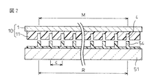
本発明者らは、上記したように、引張りに対して剛性を有する材料からなり、かつ予め施された吸湿処理によってその含水量がほぼ飽和の状態、換言すると、実質上飽和吸水している状態にある支持体を可とう性成形型で使用するのが有用であることをこのたび発見し、本発明を完成した。以下、この経緯について図2を参照しながら説明する。
【0017】
すでに図1を参照して説明したように、PDPのリブ54は、背面ガラス基板51の上に設けられてPDP用背面板を構成している。リブ54の間隔(セルピッチ)cは、画面サイズなどによって変動するけれども、通常、約150〜400μmの範囲である。一般的に、リブには、「気泡の混入や変形などの欠陥のないこと」及び「ピッチ精度がよいこと」の2点が必要とされる。ピッチ精度に関して言えば、リブは、その形成時、アドレス電極に対してほとんどずれることなく所定位置に設けられることが求められ、実際、数十μm以内の位置誤差しか許容されない。位置誤差が数十μmを上回った場合、可視光の放出条件等に悪影響が生じ、満足のいく自発光表示が不可能となる。画面サイズの大型化が進んでいる今日、このようなリブのピッチ精度の問題は深刻である。
【0018】
リブ54を全体として見た場合、基板のサイズ及びリブの形状によって若干の差はあるものの、一般的に、リブ54のトータルピッチ(両端のリブ54の距離)Rは、数十ppm以下の寸法精度が必要とされる。また、支持体1と成形層11とからなる可とう性成形型10を用いてリブ54を成形するのが有用であるが、そのような成形方法の場合、成形型10のトータルピッチ(両端の溝部4の距離)Mにも、リブ54と同様に数十ppm以下の寸法精度が必要とされる。
【0019】
ところで、従来の可とう性成形型10の場合、その支持体1に硬質プラスチックフィルムを使用するとともに、溝部4を備えた成形層11を光硬化性樹脂の成形によって形成している。支持体として使用するプラスチックフィルムは、一般的に、プラスチック原料をシート化したもので、ロールに巻き取った状態で商業的に入手可能である。ロール状のプラスチックフィルムは、その製造工程で水分を失ってしまうためにほとんど水分を含んでおらず、乾燥状態にある。このような乾燥状態にあるプラスチックフィルムに金型を併用して成形型を製造する場合、ロールからプラスチックフィルムを巻き出した段階でフィルムの吸湿がはじまり、フィルムの膨脹の結果として寸法の変動が発生する。特にこの寸法の変動は金型から成形型を取り出した直後に顕著に発生し、フィルムの寸法変動は約300〜500ppmの大きさにまで達する。よって、このような慣用の手法を使用したのでは、PDPリブ用成形型として必要とされる数十ppm以下の寸法精度を達成することができない。
【0020】
本発明者らは、金型に供給する前の成形型製造用プラスチックフィルムに適切な前処理を行うことで寸法精度の問題を解決できるのではないかと考えた結果、使用前のプラスチックフィルムに積極的に吸湿処理を施すという今までまったく予想されなかった簡単な前処理の実行に到達した。プラスチックフィルムに、例えば水又は水蒸気の吹き付け、水中又は温水中における浸漬、高温多湿雰囲気の通過などによって適切な吸湿処理を施して、フィルム中の含水量がほぼ飽和の状態とした場合、金型に供給してから金型から取り出すまでの間に、プラスチックフィルムはもはやさらに水分を吸収できない程度まで安定化されているからである。
【0021】
ここで、可とう性成形型の溝部のピッチ精度を数十ppm以内にコントロールするためには、溝部の形成に関与する成形層を構成する成形材料(好ましくは、光硬化性樹脂などの光硬化性材料)よりもはるかに硬いプラスチックフィルムを支持体に選択する必要がある。一般的に、光硬化性樹脂の硬化収縮率は数%程度であるため、軟質のプラスチックフィルムを支持体に使用した場合、前者の硬化収縮によって、支持体自体の寸法も変化し、溝部のピッチ精度を数十ppm以内にコントロールすることはできない。一方、硬質のプラスチックフィルムを使用したとすると、光硬化性樹脂が硬化収縮したとしても支持体自体の寸法精度が維持されるので、溝部のピッチ精度を高精度で維持することができる。また、プラスチックフィルムが硬質であると、リブを形成する際のピッチ変動も小さく抑えることができるため、成形性及び寸法精度の両面で有利である。本発明の実施に好適な硬質なプラスチックフィルムの例は、以下に列挙する通りである。なお、上記からも理解されるように、「硬い」あるいは「硬質」とは、これらの用語を本願明細書において使用した場合、支持体に所要の硬さを有するとともに、使用時に横方向に変形しにくく、したがって、成形型に対して所要の可とう性を付与できるような性質を指している。
【0022】
プラスチックフィルムが硬い場合、成形型の溝部のピッチ精度は、プラスチックフィルムの寸法変化にのみ依存することになるため、安定的に所望のピッチ精度を有する成形型を製造するためには、製造の前後で、フィルムの寸法が変化しないように管理することが必要である。
【0023】
一般的に、プラスチックフィルムの寸法は、周囲環境の温度及び相対湿度によって可逆的に変化する。前記したように、商業的に入手可能なプラスチックフィルムのロールは、通常、その製造工程で水分を失ってしまうためにほとんど水分を含んでいない。このため、通常の使用環境でロールからプラスチックフィルムを巻き出した場合、空気中の水分を吸収してフィルムの膨脹がおこり、寸法が増大する。例えば、厚さ188μmのポリエチレンテレフタレート(PET)フィルムをそのロールから22℃及び55%RHの環境で巻き出した場合、吸湿に原因してその寸法が徐々に増大し、約6時間を経過して310ppmの寸法増で安定化する。
【0024】
以下に説明する比較例1から理解されるように、ロールから巻き出した直後のPETフィルムを用いて成形型を製造した場合、その成形型の寸法は、製造直後では、所望の寸法をもったピッチが得られたものの、1日の経過後にはピッチの寸法が310ppmも増大した。つまり、このように、巻き出し直後のプラスチックフィルムを用いて成形型を製造した場合、所望のピッチ精度を有する成形型を得ることができない。一方、実施例1で示すように、巻き出し直後のPETフィルムを、製造環境と同一の環境(22℃及び55%RH)に曝した後、比較例1と同様な手法に従って成形型を製造した場合、所望の寸法をもったピッチが得られるとともに、そのピッチの寸法は、1日の経過後にも変化はなく、併用した金型の寸法にほぼ同じであった。つまり、フィルムを十分に吸湿させてその寸法を安定化させた後に成形型を製造した場合には、驚くべきことに、製造後の成形型の寸法変化を大幅に抑制することができる。
【0025】
また、生産性の観点から、プラスチックフィルムの吸湿処理は、できるかぎりすばやく行うことが望ましい。よって、吸湿処理を比較的に高い温度の適用下に実施することが推奨される。プラスチックフィルムの吸湿速度は、温度が上昇すればするほど速くなり、よって、前処理を高温で行えば行うほど飽和含水量への到達時間が短縮されるからである。例えば、厚さ188μmのPETフィルムの寸法を安定化するため、22℃及び55%RHの条件下では約6時間を必要としたが、この処理条件を変更して45℃及び55%RHとした場合、約1時間で寸法の安定化が可能であった。
【0026】
成形前のプラスチックフィルムに本発明に従って吸湿処理を行う場合、上述のようにできるだけ高い温度を適用して処理を実施するのが有利である。ただし、プラスチックフィルムの不所望な熱変形を抑制するため、この処理で適用する高温は、それぞれのプラスチックフィルムのガラス転移温度(Tg)を下回るものでなければならない。よって、吸湿処理に好適な処理温度は、プラスチックフィルムのTgよりも低く、かつ、なるべく高い温度ということになる。また、好適な処理温度は、使用するプラスチックフィルムごとに変動してくる。例えば、PETフィルムを使用する場合には、そのTgは約70℃であるため、60℃近傍の温度で吸湿処理を実施するのが好ましい。このように、高温下で吸湿処理を行うことで、前処理時間を大幅に短縮させることができ、生産性を上げることが可能である。
【0027】
一方、プラスチックフィルムの飽和含水量は、相対湿度によって決まるものであり、温度は影響しない。このため、吸湿工程の相対湿度は、プラスチックフィルムの製造工程と同じであることが好ましい。したがって、吸湿工程の最も好ましい処理条件は、プラスチックフィルムのTgよりも若干低い温度で、かつフィルム製造条件とほぼ同一の相対湿度ということとなる。このような処理条件の下でプラスチックフィルムの吸湿処理を施すと、製造環境の相対湿度と平衡状態となるに十分な量の水分を短時間のうちにフィルムに付与することができ、製造後の成形型の寸法変動を最小限に抑えることができる。
【0028】
以上を要するに、本発明の可とう性成形型において、その支持体は、それが引張りに対して剛性を有する材料からなり、かつ予め施された吸湿処理によってその含水量がほぼ飽和の状態にある限り、特に限定されるものではない。但し、引張りに対する剛性は、それを引張り強度で表した場合、通常、少なくとも約5kg/mm2であり、好ましくは、少なくとも約10kg/mm2である。支持体の引張り強度が5kg/mm2を下回った場合、得られた成形型を金型から取り出す時や成形型からPDPリブを取り出す時などに取り扱い性が低下し、破損や引裂けが生じることもある。
【0029】
本発明の実施において好ましい支持体は、吸湿処理の容易さ、取り扱い性などを考慮して、吸湿性のプラスチックフィルムであり、さらには硬質のプラスチックフィルムである。支持体に好適なプラスチックフィルムの例としては、以下に列挙するものに限定されるわけではないけれども、ポリエチレンテレフタレート(PET)、ポリエチレンナフタレート(PEN)、延伸ポリプロピレン、ポリカーボネート、トリアセテートなどを挙げることができる。これらのプラスチックフィルムは、単層フィルムとして使用してもよく、2種類以上を組み合わせて複合もしくは積層フィルムとして使用してもよい。
【0030】
支持体として有利に使用することのできるこれらのプラスチックフィルムは、いろいろな引張り強度を有することができる。例えば、PETの引張り強度は18kg/mm2であり、PENのそれは28kg/mm2であり、延伸ポリプロピレンのそれは19kg/mm2であり、ポリカーボネートのそれは10kg/mm2であり、そしてトリアセテートのそれは12kg/mm2である。
【0031】
また、上述のプラスチックフィルムは、材質や使用環境に応じて変動するけれども、いろいろな飽和含水量を示すことができる。例えば、PETの含水量(22℃で)は、30%RHで0.17重量%、40%RHで0.21重量%、50%RHで0.25重量%、60%RHで0.32重量%、そして70%RHで0.38重量%である。また、20℃及び50%RHで測定して、PETの含水量は0.3重量%、PENのそれは0.4重量%、延伸ポリプロピレンのそれは0.01重量%、ポリカーボネートのそれは0.2重量%、そしてトリアセテートのそれは4.4重量%である。一般的に、それぞれのプラスチックフィルムの含水量は、上記した数値の+/−50%の範囲が有効であろうと推察される。
【0032】
また、上記のようなプラスチックフィルムもしくはその他の支持体は、成形型及びPDPの構成などに応じていろいろな厚さで使用することができるけれども、通常、約0.05〜0.5mmの範囲であり、好ましくは、約0.1〜0.4mmの範囲である。支持体の厚さが上記の範囲を外れた場合には取り扱い性などが低下する。なお、支持体の厚さは、大きいほうが強度の面で有利である。
【0033】
本発明の可とう性成形型は、上述のような支持体とともに、その上に設けられ成形層を有する。成形層は、以下に詳細に説明するように、成形対象のPDPリブやその他の突起物に対応する、所定の形状及び寸法を有する溝パターンを表面に備えている。成形層は、単層で形成されていてもよいが、以下に説明するように、基層と被覆層の2層構造を有するのがさらに好ましい。なお、光硬化性成形材料を使用することを特に考慮に入れた場合、支持体及び成形層のどちらも透明であることが好ましい。
【0034】
本発明は、可とう性成形型及びそれを用いた微細構造体の製造方法にある。以下、添付の図面を参照しながら、これらの発明の好適な実施形態を説明する。ただし、当業者ならば容易に想到されるように、本発明は下記の実施形態に限定されるものではない。また、図面中、同一部分又は相当部分に対しては同一の符号を付することとする。
【0035】
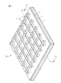
図3は、本発明の可とう性成形型の好適な一実施形態を模式的に示す部分斜視図であり、図4は、図3の線分IV−IVにそった断面図である。
【0036】
可とう性成形型10は、図示のように、予め定められた形状及び寸法をもった溝パターンをその表面に有している。溝パターンは、一定の間隔を開けて互いに交差しながら略平行に配置された複数本の溝部4をもって構成された格子状パターンである。可とう性成形型10は、もちろんその他の微細構造体の製造にも適用可能であるけれども、このように開口した格子状パターンの溝部を表面に設けて構成されているので、例えば格子状突起パターンをもったPDPリブの成形に有利に使用可能になっている。可とう性成形型10は、必要に応じて追加の層を有していたり型を構成する各層に任意の処理や加工を施していてもよいけれども、基本的には、図4に示されるように、支持体1と、その上の溝部4をもった成形層11とから構成される。なお、図示の成形層11は、基層2と被覆層3の2層からなる。
【0037】
成形層11の基層2は、10〜80℃の温度で測定した時に3000〜100000cpsの範囲の粘度を示す比較的に高い粘度をもった第1硬化性材料によってほぼ一様に形成され、気泡を実質的に又は全く含まないようになっている。また、このような第1硬化性材料は硬化しても一般に収縮し難い。したがって、この第1硬化性材料からなる溝付きの成形型は、変形し難く寸法安定性に優れるようになる。
【0038】
第1硬化性材料は、熱硬化性材料又は光硬化性材料である。特に、第1硬化性材料が光硬化性材料である場合は、可とう性成形型は長大な加熱炉を必要とすることなく比較的短時間で製造可能である。第1硬化性材料に有用な光硬化性材料には、入手の容易性から、オリゴマー(硬化性オリゴマー)が主に含まれる。特に、そのオリゴマーがウレタンアクリレートオリゴマー及び/又はエポキシアクリレートオリゴマー等のアクリル系オリゴマーである場合は、基層が光学的に透明になる。したがって、後述する透明な被覆層との組み合わせにより、可とう性成形型は、光硬化性の成形材料を使用することができるようになる。可とう性成形型を介しても、かかる成形材料に光を照射することができるからである。
【0039】
基層2の表面には、それと密着して被覆層3が設けられ、また、その際、基層2とその上の被覆層3の間には気泡が存在しないようになっている。被覆層3は、10〜80℃の温度で測定した時に200cps以下の粘度を示す比較的に低い粘度をもった第2硬化性材料によってほぼ一様に形成され、気泡を実質的に又は全く含まないようになっている。また、この第2硬化性材料は、好ましくは、低タック性である。被覆層3が低タック性を示すことにより、可とう性成形型の表面の粘着性が低くなり、ハンドリング性が向上するばかりでなく、成形型が基板や製造装置に貼り付くことが防止される。
【0040】
第2硬化性材料は、第1硬化性材料と同様、熱硬化性材料及び光硬化性材料のいずれであってもよい。ただし、第1硬化性材料と異なり、第2硬化性材料に有用な光硬化性材料にはモノマー(硬化性モノマー)が含まれる。特に、モノマーがアクリルアミド、アクリロニトリル、アクリル酸、アクリル酸エステルその他のアクリル系モノマーであると、被覆層が光学的に透明になる。したがって、そのような可とう性成形型は、上述したように、透明な基層との組み合わせにより、光硬化性の成形材料を使用可能となる。
【0041】
成形層11を担持する支持体1は、すでに詳細に説明したように、好ましくはプラスチックフィルムであり、また、その厚さは、通常、約0.05〜0.5mmの範囲である。また、支持体は、好ましくは光学的に透明である。支持体が光学的に透明であると、硬化のために照射する光がこの支持体を透過可能であるので、光硬化性の第1硬化性材料及び第2硬化性材料を用いてそれぞれ基層及び被覆層を形成することができる。特に、支持体が透明材料によって均一に形成されている場合は、均一な基層及び被覆層をより効果的に形成することができる。典型的な透明の支持体の例は、上記した通りである。
【0042】
本発明の可とう性成形型は、いろいろな技法に従って製造することができる。例えば光硬化性の第1硬化性材料と第2硬化性材料を成形層の形成に用いた場合、図5及び図6に順を追って示すような手順によって本発明の成形型を有利に製造することができる。
【0043】
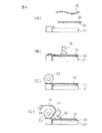
まず、図5(A)に示すように、製造対象の可とう性成形型に対応する形状及び寸法を備えた金型5、透明なプラスチックフィルムからなる支持体(以下、支持フィルムと呼ぶ)1及び及びラミネートロール23を用意する。ここで、可とう性成形型は特にPDP用背面板の製造に用いられるものであるので、金型5は、PDP用背面板のリブと同じパターン及び形状の隔壁14をその表面に備え、また、したがって、相隣りあう隔壁14によって規定される空間(凹部)15が、PDPの放電表示セルとなるところである。ラミネートロール23は、支持フィルム1を金型5に押し付けるもので、必要ならば、これに代えてその他の周知・慣用のラミネート手段を使用してもよい。
【0044】
次いで、図5(B)に示すように、例えばナイフコータやバーコータ等の周知・慣用のコーティング手段(図示せず)により、支持フィルム1の片面に光硬化性の第1硬化性材料2を所定の厚さで均一に塗布する。また、同様の方法で、金型5の隔壁保持表面に光硬化性の第2硬化性材料3を所定の厚さで塗布し、隔壁14の間隙に形成された凹部15に充填する。本発明によれば、この第2硬化性材料3は低粘度のために流動し易くなっている。したがって、金型5に高いアスペクト比をもった隔壁14があったとしても、気泡を取り込むことなく第2硬化性材料3を均一に充填可能となる。
【0045】
その後、図5(C)に示すように、ラミネートロール23を金型5の上を矢印Aの方向に、第1硬化性材料2と第2硬化性材料3とを密着させながら滑動させる。このラミネート処理の結果、第2硬化性材料3を凹部15の実質的な部分から均一に排除できる。
【0046】
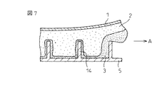
また、このラミネート処理の際、隔壁14の頂部(自由端部)から支持フィルム1までの距離を隔壁の高さより十分に長く(例えば、隔壁の高さの1/10以上に)保ちながら、両硬化性材料を密着させるのが好適である。図7に示されるように、第2硬化性材料3の大部分を隔壁14の間隙から効果的に排除して、第1硬化性材料2に置換できるからである。その結果、成形型の溝パターンを、被覆層3のほか基層2によっても形成することができるようになる。
【0047】
ラミネート処理が完了した後、図6(D)に示すように、支持フィルム1を金型5に積層した状態で、支持フィルム1を介して、光(hν)を矢印で示すように第1硬化性材料2と第2硬化性材料3に照射する。ここで、支持フィルム1が気泡等の光散乱要素を含むことなく、透明材料によって一様に形成されていれば、照射光は、ほとんど減衰することがなく、第1硬化性材料2と第2硬化性材料3に均等に到達可能である。その結果、第1硬化性材料は効率的に硬化して支持フィルム1に接着した均一な基層2になる。また、第2硬化性材料も同様に硬化して、基層2と接着した均一な被覆層3になる。
【0048】
上述のような一連の製造工程を経て、支持フィルム1、基層2、そして被覆層3が一体的に接合した可とう性成形型が得られる。その後、図6(E)に示すように、可とう性成形型10をその一体性を保持したまま金型5から分離する。
【0049】
この可とう性成形型は、寸法・大きさによらず、それに応じた周知・慣用のラミネート手段及びコーティング手段を使用しさえすれば、比較的簡便に製造可能である。したがって、本発明によれば、真空プレス成形機等の真空設備を使用した従来の製造方法とは異なり、何らの制限を受けることなく大型の可とう性成形型を簡便に製造可能となる。
【0050】
さらに加えて、本発明の可とう性成形型は、いろいろな微細構造体の製造において有用である。特に、本発明の成形型は、例えば特開2001−191345号公報に開示されているように、格子パターンをもったPDPのリブの成形に極めて有用である。この可とう性成形型を使用すれば、真空設備及び/又は複雑なプロセスの代わりにラミネートロールを用いただけで、放電表示セルから外部に紫外線が漏れ難い格子状リブを有する大画面のPDPを簡便に製造することができるからである。
【0051】
次いで、特開2001−191345号公報の図1〜図3に示した製造装置を使用してガラス平板上にリブを設けたPDP用基板を製造する方法を、図8及び図9を参照して説明する。
【0052】
まず、図8(A)に示すように、一定の間隔をあけて互いに平行に電極32を配設したガラス平板31を予め用意して支持台21上に配置する。また、図示しないけれども、もしも変位可能なステージを使用しているのであるならば、そのステージの上に、ガラス平板31を配置した支持台21を所定位置に載置する。
【0053】
次いで、溝パターンを表面に有する本発明の可とう性成形型10をガラス平板31上の所定の位置に設置する。
【0054】
次いで、ガラス平板31と成形型10との位置合わせを行う。詳細に述べると、この位置合わせは、目視によって行うか、さもなければ、図8(B)に示すように、例えばCCDカメラのようなセンサ29を用いて、成形型10の溝部とガラス平板31の電極とを平行にするようにして行う。このとき、必要により、温度及び湿度を調整して成形型10の溝部とガラス平板31上の相隣れる電極間の間隔を一致させてもよい。通常、成形型10とガラス平板31は温度及び湿度の変化に応じて伸縮し、また、その程度は互いに異なるからである。したがって、ガラス平板31と成形型10との位置合わせが完了した後は、そのときの温度及び湿度を一定に維持するよう制御する。かかる制御方法は、大面積のPDP用基板の製造に当たって特に有効である。
【0055】
引き続いて、図8(C)に示すように、ラミネートロール23を成形型10の一端部に載置する。このとき、成形型10の一端部はガラス平板31上に固定されているのが好ましい。先に位置合わせが完了したガラス平板31と成形型10との位置ずれが防止され得るからである。
【0056】
次に、図8(D)に示すように、成形型10の自由な他端部をホルダー28によって持ち上げてラミネートロール23の上方に移動させ、ガラス平板31を露出させる。このとき、成形型10には張力を与えないようにする。成形型10にしわが入るのを防止したり、成形型10とガラス平板31の位置合わせを維持したりするためである。但し、その位置合わせを維持し得る限り、他の手段を使用してもよい。それから、リブの形成に必要な一定量のリブ前駆体33をガラス平板31の上に供給する。図示の例では、リブ前駆体供給装置としてノズル付きのペースト用ホッパー27を使用している。
【0057】
ここで、リブ前駆体とは、最終的に目的とするリブ成形体を形成可能な任意の成形材料を意味し、リブ成形体を形成できる限り特に限定されるものではない。リブ前駆体は、熱硬化性でも光硬化性でもよい。特に、光硬化性のリブ前駆体は、図9(F)に示すように、上述した透明の可とう性成形型と組み合せてきわめて効果的に使用可能である。上記可とう性成形型は気泡や変形等の欠陥をほとんど伴わず、光の不均一な散乱等を抑制することができる。かくして、成形材料が均一に硬化され、一定かつ良好な品質をもったリブになる。
【0058】
リブ前駆体に好適な組成の一例を挙げると、(1)リブの形状を与える、例えば酸化アルミニウムのようなセラミック成分、(2)セラミック成分間の隙間を埋めてリブに緻密性を付与する鉛ガラスやリン酸ガラスのようなガラス成分、及び(3)セラミック成分を収容及び保持して互いに結合するバインダ成分とその硬化剤又は重合開始剤を基本的に含む組成物である。バインダ成分の硬化は、加熱又は加温によらず光の照射によってなされることが望ましい。かかる場合、ガラス平板の熱変形を考慮する必要はなくなる。また、必要に応じて、この組成物には、クロム(Cr)、マンガン(Mn)、鉄(Fe)、コバルト(Co)、ニッケル(Ni)、銅(Cu)、亜鉛(Zn)、インジウム(In)又は錫(Sn)、ルテニウム(Ru)、ロジウム(Rh)、パラジウム(Pd)、銀(Ag)、イリジウム(Ir)、プラチナ(Pt)、金(Au)もしくはセリウム(Ce)の酸化物、塩又は錯体からなる酸化触媒が添加されて、バインダ成分の除去温度を低下させてもよい。
【0059】
また、図示の製造方法の実施に当たっては、リブ前駆体33をガラス平板31上の全体に均一に供給しない。図8(D)に示すように、ラミネートロール23の近傍のガラス平板31上にリブ前駆体33を供給するだけでよい。後述の工程でラミネートロール23が成形型10上を移動するときにガラス平板31の上に均一にリブ前駆体33を広げることができるからである。ただし、このような場合、リブ前駆体33には通常約100,000cps以下、好適には約20,000cps以下の粘度が付与されていることが望ましい。リブ前駆体の粘度が約100,000cpsより高いと、ラミネートロールによってリブ前駆体が十分に広がり難くなり、その結果、成形型の溝部に空気が巻き込まれ、リブの欠陥の原因となるおそれがある。実際、リブ前駆体の粘度が約100,000cps以下であると、ラミネートロールをガラス平板の一端部から他端部に一回だけ移動させるだけで、ガラス平板と成形型の間にリブ前駆体が均一に広がり、全ての溝部に気泡を含むことなく均一に充填できる。但し、リブ前駆体の供給は、上述の方法に限定されるものではない。例えば、図示しないが、リブ前駆体をガラス平板の全面にコーティングしてもよい。このとき、コーティング用のリブ前駆体は、上記と同様の粘度を有している。特に、格子状パターンのリブを形成する場合には、その粘度は、約20,000cps以下、好ましくは約5,000cps以下である。
【0060】
次に、回転モータ(図示せず)を駆動させ、図9(E)において矢印で示すように、ラミネートロール23を成形型10上を所定の速度で移動させる。ラミネートロール23がこのようにして成形型10上を移動している間、成形型10にはその一端部から他端部に圧力がラミネートロール23の自重によって順次印加されて、ガラス平板31と成形型10の間にリブ前駆体33が広がり、成形型10の溝部に成形材料が充填される。すなわち、リブ前駆体33が順次溝部の空気と置換されて充填されていく。このとき、リブ前駆体の厚さは、リブ前駆体の粘度又はラミネートロールの直径、重量もしくは移動速度を適当に制御することにより、数μmから数十μmの範囲にすることができる。
【0061】
また、図示の製造方法によれば、成形型の溝部は空気のチャネルにもなって、空気をそこに捕捉したとしても、上述した印加圧力を受けたときには空気を効率よく成形型の外部又は周囲に排除することができる。その結果、本製造方法は、リブ前駆体の充填を大気圧下で行っても、気泡の残存を防止することができるようになる。換言すれば、リブ前駆体の充填に当たって減圧を適用する必要はなくなる。もちろん、減圧を行って、気泡の除去を一層容易に行ってもよい。
【0062】
引き続いて、リブ前駆体を硬化させる。ガラス平板31上に広げたリブ前駆体33が光硬化可能である場合は、特に、図9(F)に示すように、ガラス平板31及び成形型10と共にリブ前駆体(図示せず)を光照射装置26に入れ、紫外線(UV)のような光をガラス平板31及び/又は成形型10を介してリブ前駆体に照射して硬化させる。このようにして、リブ前駆体の成形体、すなわち、リブそのものが得られる。
【0063】
最後に、得られたリブをガラス平板31に接着させたまま、ガラス平板31及び成形型10を光照射装置から取り出した後、図9(G)に示されるように成形型10を剥離除去する。本発明の成形型はハンドリング性にも優れるので、この成形型において被覆層に粘着性の低い材料を用いた場合、ガラス平板に接着したリブを破損させることなく成形型を容易に剥離除去できる。
【0064】
以上、本発明を好適な実施形態にしたがって説明したが、本発明はこれに限定されるものではない。
【0065】
本発明の目的及び作用効果を達成することができる限り、可とう性成形型は上記した形態のものに限定されない。例えば、ここでは図示していないが、可とう性成形型が、複数本の溝部を上述のように交差させないで、一定の間隔をあけて互いに略平行に配置して形成した、いわゆるストレートの溝パターンを備えてもよい。このような可とう性成形型は、ストレートパターンのPDPのリブを成形するために使用可能である。
【0066】
また、本発明の可とう性成形型は、PDPのリブの成形にのみ使用されるのではなく、同様な形状、パターンを有する各種の微細構造体の成形にも有利に応用することができる。
【0067】
さらに、本発明によれば、先に図1を参照して説明したPDPやその他のタイプのPDPを有利に製造することができる。PDPの構造、寸法等の詳細は、すでに広く知られているので、ここでの説明を省略する。
【0068】
【実施例】
本発明をその実施例にしたがって具体的に説明する。なお、本発明は下記の実施例に限定されるものでないことは、当業者ならば容易に理解されるであろう。実施例1
本例では、PDP用背面板の製造のため、ストレートパターンのリブ(隔壁)をもった長方形の金型を用意した。詳細に述べると、この金型は、その長手方向に沿って等脚台形の断面をもったリブを一定のピッチで配置したもので、相隣接するリブによって規定される空間(凹部)が、PDPの放電表示セルに対応する。それぞれのリブは、高さ208μm、頂部幅55μm、底部幅115μm、そしてピッチ(隣接するリブの中心間の距離)359.990μmであり、また、リブの本数は、2943本であった。また、リブのトータルピッチ(両端のリブの中心間の距離)は、(2943−1)×0.35999=1059.091mmであった。
【0069】
また、80重量%の脂肪族ウレタンアクリレートオリゴマー(ヘンケル社製、商品名「フォトマー6010」)、20重量%の1,6−ヘキサンジオールジアクリレート(新中村化学社製)及び1重量%の2−ヒドロキシ−2−メチル−1−フェニル−プロパン−1−オン(チバ・スペシャリティ・ケミカルズ社製、商品名「ダロキュア1173」)を混合して光硬化性樹脂を調製した。この光硬化性樹脂の粘度をブルックフィールド粘度計(B型粘度計)を用いて測定したところ、22℃で8500cpsであった。
【0070】
さらに、成形型の支持体として使用するため、ロールに巻かれた幅1300mm及び厚さ188μmのPETフィルム(テイジン社製、商品名「HPE188」)を用意した。このPETフィルムを22℃及び55%RHの環境下でロールから巻き出し、そのまま6時間放置した。PETフィルムの含水量は、約0.30重量%であった。
【0071】
引き続いて、22℃及び55%RHの環境を維持した状態で、以下の手順に従って成形型を製造し、検査を行った。
【0072】
用意しておいた金型の上流端に、先の工程で調製した光硬化性樹脂をライン状に塗布した。次いで、その金型の表面を覆うように、上記のようにして吸湿処理を完了したPETフィルムをラミネートした。ラミネートロールを使用してPETフィルムを入念に押し付けたところ、金型の凹部に光硬化性樹脂が充填された。
【0073】
この状態で、三菱電機オスラム社製の蛍光ランプを用い、300〜400nmに波長をもった光を、PETフィルムを介して、光硬化性樹脂に30秒間照射した。光硬化性樹脂が硬化し、成形層が得られた。引き続いてPETフィルムを成形層と共に金型から剥離し、金型のリブに対応する形状及び寸法を有する多数の溝部を備えた可とう性成形型を得た。
【0074】
成形型を金型から剥離直後を始点として、成形型のトータルピッチを経時的に測定したところ、下記の第1表に記載のような測定結果が得られた。
比較例1
前記実施例1に記載の手法に従って可とう性成形型を製造し、検査したが、本例では、比較のため、ロールに巻かれたPETフィルムに吸湿処理を施すことなく、22℃及び55%RHの環境下でロールから巻き出した直後にただちに使用した。
【0075】
実施例1と同様に、成形型を金型から剥離直後を始点として、成形型のトータルピッチを経時的に測定したところ、下記の第1表に記載のような測定結果が得られた。
【0076】
【表1】

上記第1表の測定結果から理解されるように、実施例1の成形型では、そのトータルピッチは、製造直後から1日経過後の間で約20ppmの変化量しか示さなかった。この変化量は、ターゲットとなる金型のトータルピッチに対して最大でも約20ppmの誤差しかないことを意味し、PDPリブ用の成形型に必要とされる数十ppm以内の寸法精度を十分に満たしていると言える。
【0078】
これに対して、比較例1の成形型では、そのトータルピッチは、製造直後では実施例1のそれにほぼ同じであったけれども、経時とともに徐々に増大し、1日経過後で約310ppmの変化量を示した。つまり、ターゲットとなる金型のトータルピッチに対して、1日経過後の成形型のトータルピッチは約310ppmも大きく、PDPリブ用の成形型に必要とされる寸法精度を満たすことができなかった。
【0079】
【発明の効果】
以上に説明したように、本発明によれば、PDPリブあるいはその他の微細構造体を製造するのに有用で、熟練を必要とすることなく、所定位置にリブ等の突起物を容易かつ正確に、高い寸法精度で設けることができる可とう性成形型を提供することができる。
【0080】
また、本発明によれば、PDPリブあるいはその他の微細構造体を製造するのに有用で、気泡の発生、パターンの変形等の欠陥を伴わないで高精度に製造できる可とう性成形型を提供することができる。
【0081】
また、本発明によれば、PDPリブあるいはその他の微細構造体を比較的簡便かつ広範囲に製造するために有効な可とう性成形型を提供することができる。
【0082】
さらに、本発明によれば、このような可とう性成形型を用いた、例えばセラミック微細構造体などの微細構造体の製造方法を提供することもできる。
【図面の簡単な説明】
【図1】本発明も適用可能な、従来のPDPの一例を模式的に示した断面図である。
【図2】可とう性成形型における寸法精度の重要性を説明した断面図である。
【図3】本発明による可とう性成形型の1実施形態を示した斜視図である。
【図4】図3の線分IV−IVにそった断面図である。
【図5】本発明による可とう性成形型の1製造方法(前半の工程)を順を追って示した断面図である。
【図6】本発明による可とう性成形型の1製造方法(後半の工程)を順を追って示した断面図である。
【図7】本発明の成形型の製造工程における第1及び第2硬化性材料の分布を示した断面図である。
【図8】本発明によるPDP用背面板の1製造方法(前半の工程)を順を追って示した断面図である。
【図9】本発明によるPDP用背面板の1製造方法(後半の工程)を順を追って示した断面図である。
【符号の説明】
1…支持体
2…基層
3…被覆層
4…溝部
5…金型
10…可とう性成形型
11…成形層[0001]
BACKGROUND OF THE INVENTION
The present invention relates to a molding technique, and more specifically, relates to a flexible mold and a method for manufacturing a fine structure using the same. The microstructure manufacturing method of the present invention is advantageous for manufacturing ribs of a back plate for a plasma display panel, for example.
[0002]
[Prior art]
It is well known that cathode ray tube (CRT) display devices have been mass-produced economically with the progress and development of television technology. However, in recent years, thin and light flat panel displays have been attracting attention as next-generation display devices in place of the CRT display devices.
[0003]
One of the typical flat panel displays is a liquid crystal display (LCD), which is a small display device for notebook personal computers, mobile phones, personal digital assistants (PDAs), or other portable electronic information devices. As already used. On the other hand, a plasma display panel (PDP) is typical as a flat panel display having a thin and large screen, and is actually being used as a wall-mounted television for business use and recently for home use.
[0004]
As an example for reference, FIG. 1 schematically shows an example of a PDP. The
[0005]
In general, the rib is made of a ceramic fine structure, and is usually provided in advance on the back glass substrate together with the address electrode to constitute a back plate for PDP. In particular, International Publication No. 00/39829 pamphlet, Japanese Patent Application Laid-Open No. 2001-191345 and Japanese Patent Application Laid-Open No. Hei 8-273538 disclose that a curable ceramic paste and a flexible mold are used for manufacturing such a back plate for PDP. Is disclosed. This flexible mold has a molding layer on the support that has a groove with a fixed pattern on the surface. Due to its flexibility, this groove can be easily filled with curable ceramic paste without bubbles. Can be done. In addition, when this flexible mold is used, the mold can be released after the paste is cured without damaging the ceramic microstructure (ie, ribs) and the glass substrate.
[0006]
By the way, in the manufacture of the PDP back plate, it is further required that ribs are provided at predetermined positions with almost no deviation from the address electrodes. This is because an excellent self-luminous display in the PDP becomes possible as the rib is accurately provided at a predetermined position and the dimensional accuracy is higher.
[0007]
In particular, when manufacturing a PDP back plate using a flexible mold as described above, it is possible to easily and accurately provide ribs at predetermined positions with high dimensional accuracy without requiring skill. Very desirable. This is because when the rib is formed by the flexible mold, the air bubbles are not taken in as described above and the rib is not damaged, so that the obtained rib itself is excellent in quality.
[0008]
[Problems to be solved by the invention]
The object of the present invention is to solve the above-mentioned problems of the prior art, and one of the objects is useful for manufacturing PDP ribs or other fine structures and requires skill. An object of the present invention is to provide a flexible mold capable of easily and accurately providing a projection such as a rib at a predetermined position with high dimensional accuracy.
[0009]
Another object of the present invention is a flexible molding that is useful for manufacturing PDP ribs or other fine structures, and can be manufactured with high accuracy without defects such as bubble generation and pattern deformation. To provide a mold.
[0010]
Another object of the present invention is to provide a flexible mold effective for manufacturing PDP ribs or other fine structures relatively easily and in a wide range.
[0011]
Furthermore, another object of the present invention is to provide a method for producing a fine structure such as a ceramic fine structure using such a flexible mold.
[0012]
These and other objects of the present invention will be readily understood from the following detailed description.
[0013]
[Means for Solving the Problems]
As a result of intensive studies to achieve the above-mentioned object, the present inventors have used the dimensions of the support constituting the mold for the above-mentioned problems recognized in the conventional flexible mold. Variations due to environmental conditions, i.e. temperature and relative humidity conditions during use, are greatly involved, and therefore, if the mold can maintain a desired constant dimension for a certain period at least in its usage environment, it will not be solved until now. The present inventors have found that the problems that were considered possible can be solved, and have completed the present invention. The support found by the present inventors is a support made of a material having rigidity against tension and having a water content almost saturated by a moisture absorption treatment applied in advance.
[0014]
Accordingly, the present invention has at least 5 kg / mm in one aspect.2A support made of a material having a tensile strength of and saturated with moisture at the temperature and relative humidity at the time of use by a moisture absorption treatment performed in advance,
A molding layer provided on the support and provided with a groove pattern on the surface having a predetermined shape and dimensions;
It is in the flexible shaping | molding die characterized by comprising.
[0015]
According to another aspect of the present invention, there is provided a method of manufacturing a fine structure having a protrusion pattern having a predetermined shape and dimensions on a surface of a substrate on the other surface, the following steps:
At least 5 kg / mm2And a support body that is saturated with moisture at a temperature and relative humidity at the time of use by a moisture absorption treatment performed in advance and corresponds to the protrusion pattern. A step of preparing a flexible mold having a molding layer having a groove pattern having a shape and dimensions on the surface, and a curable molding material is disposed between the substrate and the molding layer of the mold Filling the groove pattern of the mold with the molding material,
Curing the molding material to form a microstructure comprising the substrate and a protrusion pattern integrally coupled thereto;
Removing the microstructure from the mold,
In the manufacturing method of the fine structure characterized by comprising.
[0016]
DETAILED DESCRIPTION OF THE INVENTION
As described above, the inventors of the present invention are made of a material having rigidity against tension, and the moisture content is almost saturated by the moisture absorption treatment applied in advance, in other words, the state is substantially saturated water absorption. It has now been discovered that it is useful to use a support in a flexible mold, and the present invention has been completed. Hereinafter, this process will be described with reference to FIG.
[0017]
As already described with reference to FIG. 1, the
[0018]
When the
[0019]
By the way, in the case of the conventional flexible shaping | molding die 10, while using the hard plastic film for the
[0020]
As a result of thinking that the problem of dimensional accuracy can be solved by performing an appropriate pretreatment on the plastic film for mold production before being supplied to the mold, the present inventors have actively applied the plastic film before use. A simple pretreatment that has never been anticipated until now has been achieved. If the plastic film is subjected to appropriate moisture absorption treatment by, for example, spraying water or water vapor, immersing in water or warm water, passing through a high-temperature and high-humidity atmosphere, and the moisture content in the film is almost saturated, This is because the plastic film is stabilized to the extent that it can no longer absorb moisture between the time when it is supplied and the time when it is taken out from the mold.
[0021]
Here, in order to control the pitch accuracy of the groove portion of the flexible mold within tens of ppm, the molding material constituting the molding layer involved in the formation of the groove portion (preferably photocuring such as a photocurable resin) It is necessary to select a plastic film that is much harder than the support material. In general, since the curing shrinkage of photo-curing resin is about several percent, when a soft plastic film is used for the support, the size of the support itself changes due to the former curing shrinkage, and the pitch of the grooves The accuracy cannot be controlled within tens of ppm. On the other hand, if a hard plastic film is used, the dimensional accuracy of the support itself is maintained even when the photocurable resin is cured and shrunk, so that the pitch accuracy of the grooves can be maintained with high accuracy. Further, if the plastic film is hard, the pitch fluctuation when forming the rib can be suppressed to be small, which is advantageous in terms of both formability and dimensional accuracy. Examples of rigid plastic films suitable for the practice of the present invention are listed below. As understood from the above, “hard” or “hard” means that the term “hard” or “hard” means that the support has the required hardness and deforms in the lateral direction during use. Therefore, it refers to a property that can give the required flexibility to the mold.
[0022]
When the plastic film is hard, the pitch accuracy of the groove of the mold depends only on the dimensional change of the plastic film. Therefore, in order to stably manufacture a mold having the desired pitch accuracy, Therefore, it is necessary to manage so that the dimensions of the film do not change.
[0023]
In general, the dimensions of a plastic film change reversibly with the temperature and relative humidity of the surrounding environment. As noted above, commercially available plastic film rolls typically contain little moisture because they lose moisture during the manufacturing process. For this reason, when a plastic film is unwound from a roll in a normal use environment, the film expands by absorbing moisture in the air, and the dimensions increase. For example, when a polyethylene terephthalate (PET) film having a thickness of 188 μm is unwound from the roll in an environment of 22 ° C. and 55% RH, the dimensions gradually increase due to moisture absorption, and about 6 hours have passed. Stabilizes with a dimension increase of 310 ppm.
[0024]
As will be understood from Comparative Example 1 described below, when a mold was manufactured using a PET film immediately after unrolling from the roll, the dimensions of the mold had a desired dimension immediately after the manufacture. Although a pitch was obtained, the pitch dimension increased by 310 ppm after one day. That is, when a mold is manufactured using a plastic film immediately after unwinding as described above, a mold having a desired pitch accuracy cannot be obtained. On the other hand, as shown in Example 1, after exposing the PET film immediately after unwinding to the same environment (22 ° C. and 55% RH) as the production environment, a mold was produced according to the same method as in Comparative Example 1. In this case, a pitch having a desired dimension was obtained, and the dimension of the pitch did not change even after the passage of one day, and was almost the same as the dimension of the die used together. That is, when the mold is manufactured after the film is sufficiently absorbed to stabilize its dimensions, surprisingly, the dimensional change of the mold after manufacture can be greatly suppressed.
[0025]
From the viewpoint of productivity, it is desirable that the moisture absorption treatment of the plastic film is performed as quickly as possible. Therefore, it is recommended that the moisture absorption treatment be performed under application of a relatively high temperature. This is because the moisture absorption rate of the plastic film increases as the temperature rises, and therefore, the time for reaching the saturated water content decreases as the pretreatment is performed at a higher temperature. For example, in order to stabilize the dimension of a PET film having a thickness of 188 μm, about 6 hours were required under the conditions of 22 ° C. and 55% RH, but this processing condition was changed to 45 ° C. and 55% RH. In the case, the dimension could be stabilized in about 1 hour.
[0026]
When the moisture absorption treatment is performed on the plastic film before molding according to the present invention, it is advantageous to apply the treatment by applying the highest possible temperature as described above. However, in order to suppress undesired thermal deformation of the plastic film, the high temperature applied in this treatment must be below the glass transition temperature (Tg) of the respective plastic film. Therefore, the treatment temperature suitable for the moisture absorption treatment is lower than the Tg of the plastic film and as high as possible. Further, the suitable processing temperature varies depending on the plastic film used. For example, when a PET film is used, the Tg is about 70 ° C., and therefore it is preferable to perform the moisture absorption treatment at a temperature around 60 ° C. As described above, by performing the moisture absorption treatment at a high temperature, the pretreatment time can be significantly shortened, and the productivity can be increased.
[0027]
On the other hand, the saturated water content of the plastic film is determined by the relative humidity, and the temperature has no effect. For this reason, it is preferable that the relative humidity of a moisture absorption process is the same as the manufacturing process of a plastic film. Therefore, the most preferable processing condition of the moisture absorption process is a temperature slightly lower than the Tg of the plastic film and a relative humidity substantially the same as the film manufacturing condition. When the moisture absorption treatment of the plastic film is performed under such treatment conditions, a sufficient amount of moisture can be imparted to the film in a short time to reach equilibrium with the relative humidity of the production environment. Variations in the dimensions of the mold can be minimized.
[0028]
In short, in the flexible mold according to the present invention, the support is made of a material having rigidity against tension, and its water content is almost saturated due to the moisture absorption treatment applied in advance. As long as it is not particularly limited. However, the rigidity against tension is usually at least about 5 kg / mm when expressed in terms of tensile strength.2Preferably at least about 10 kg / mm2It is. The tensile strength of the support is 5 kg / mm2If it is less than, the handleability is lowered when the obtained mold is taken out of the mold or when the PDP rib is taken out of the mold, and breakage or tearing may occur.
[0029]
In the practice of the present invention, a preferable support is a hygroscopic plastic film in consideration of easiness of the hygroscopic treatment, handleability and the like, and further a hard plastic film. Examples of plastic films suitable for the support are not limited to those listed below, but include polyethylene terephthalate (PET), polyethylene naphthalate (PEN), stretched polypropylene, polycarbonate, triacetate, and the like. it can. These plastic films may be used as a single layer film, or may be used as a composite or laminated film by combining two or more kinds.
[0030]
These plastic films, which can be used advantageously as a support, can have various tensile strengths. For example, the tensile strength of PET is 18 kg / mm2And that of PEN is 28kg / mm2It is 19 kg / mm for stretched polypropylene.2And that of polycarbonate is 10 kg / mm2And that of triacetate is 12 kg / mm2It is.
[0031]
Moreover, although the above-mentioned plastic film changes according to a material and use environment, it can show various saturated water content. For example, the moisture content of PET (at 22 ° C.) is 0.17% by weight at 30% RH, 0.21% by weight at 40% RH, 0.25% by weight at 50% RH, and 0.32 at 60% RH. % By weight, and 0.38% by weight at 70% RH. Also, when measured at 20 ° C. and 50% RH, the water content of PET is 0.3% by weight, that of PEN is 0.4% by weight, that of stretched polypropylene is 0.01% by weight, that of polycarbonate is 0.2% by weight. %, And that of triacetate is 4.4% by weight. In general, it is assumed that the range of +/− 50% of the above numerical values will be effective for the water content of each plastic film.
[0032]
In addition, the plastic film or other support as described above can be used in various thicknesses depending on the configuration of the mold and the PDP, but is usually in the range of about 0.05 to 0.5 mm. Yes, preferably in the range of about 0.1 to 0.4 mm. When the thickness of the support is out of the above range, the handleability is lowered. Note that a larger support thickness is advantageous in terms of strength.
[0033]
The flexible mold according to the present invention has a molding layer provided on the support body as described above. As will be described in detail below, the molding layer has a groove pattern on the surface that has a predetermined shape and dimensions corresponding to the PDP rib and other protrusions to be molded. The molding layer may be formed of a single layer, but as described below, it is more preferable to have a two-layer structure of a base layer and a coating layer. In addition, when taking into consideration the use of a photocurable molding material, both the support and the molding layer are preferably transparent.
[0034]
The present invention resides in a flexible mold and a method for producing a fine structure using the same. Hereinafter, preferred embodiments of these inventions will be described with reference to the accompanying drawings. However, as will be readily appreciated by those skilled in the art, the present invention is not limited to the following embodiments. In the drawings, the same or corresponding parts are denoted by the same reference numerals.
[0035]
FIG. 3 is a partial perspective view schematically showing a preferred embodiment of the flexible mold of the present invention, and FIG. 4 is a cross-sectional view taken along line IV-IV in FIG.
[0036]
As shown in the figure, the
[0037]
The
[0038]
The first curable material is a thermosetting material or a photocurable material. In particular, when the first curable material is a photocurable material, the flexible mold can be manufactured in a relatively short time without requiring a long heating furnace. The photocurable material useful for the first curable material mainly contains an oligomer (curable oligomer) from the viewpoint of availability. In particular, when the oligomer is an acrylic oligomer such as a urethane acrylate oligomer and / or an epoxy acrylate oligomer, the base layer becomes optically transparent. Therefore, a flexible molding die can use a photocurable molding material by combination with a transparent coating layer to be described later. This is because the molding material can be irradiated with light even through a flexible mold.
[0039]
A
[0040]
Similar to the first curable material, the second curable material may be either a thermosetting material or a photocurable material. However, unlike the first curable material, the photocurable material useful for the second curable material includes a monomer (curable monomer). In particular, when the monomer is acrylamide, acrylonitrile, acrylic acid, acrylic ester or other acrylic monomer, the coating layer becomes optically transparent. Therefore, such a flexible mold can use a photocurable molding material in combination with a transparent base layer as described above.
[0041]
As already described in detail, the
[0042]
The flexible mold of the present invention can be manufactured according to various techniques. For example, when the photocurable first curable material and the second curable material are used for forming the molding layer, the molding die of the present invention is advantageously manufactured by the procedure shown in order in FIGS. 5 and 6. be able to.
[0043]
First, as shown in FIG. 5A, a
[0044]
Next, as shown in FIG. 5 (B), the photocurable first
[0045]
Thereafter, as shown in FIG. 5C, the
[0046]
Further, during the laminating process, while maintaining the distance from the top (free end) of the
[0047]
After the laminating process is completed, as shown in FIG. 6D, in the state where the
[0048]
Through a series of manufacturing steps as described above, a flexible mold in which the
[0049]
This flexible mold can be manufactured comparatively simply by using well-known and conventional laminating means and coating means corresponding to the dimensions and sizes. Therefore, according to the present invention, unlike a conventional manufacturing method using vacuum equipment such as a vacuum press molding machine, a large flexible mold can be easily manufactured without any limitation.
[0050]
In addition, the flexible mold of the present invention is useful in the production of various microstructures. In particular, the mold according to the present invention is extremely useful for forming ribs of PDP having a lattice pattern, as disclosed in, for example, Japanese Patent Application Laid-Open No. 2001-191345. If this flexible mold is used, simply using a laminate roll instead of vacuum equipment and / or a complicated process, a large-screen PDP having grid ribs that hardly leak ultraviolet rays from the discharge display cell can be easily used. This is because it can be manufactured.
[0051]
Next, a method for manufacturing a PDP substrate having ribs on a glass plate using the manufacturing apparatus shown in FIGS. 1 to 3 of JP-A-2001-191345 will be described with reference to FIGS. explain.
[0052]
First, as shown in FIG. 8 (A), a glass
[0053]
Next, the
[0054]
Next, the glass
[0055]
Subsequently, as shown in FIG. 8C, the
[0056]
Next, as shown in FIG. 8D, the free other end of the
[0057]
Here, the rib precursor means any molding material capable of finally forming a target rib molded body, and is not particularly limited as long as the rib molded body can be formed. The rib precursor may be thermosetting or photocurable. In particular, the photocurable rib precursor can be used very effectively in combination with the above-described transparent flexible mold as shown in FIG. 9 (F). The flexible mold is hardly accompanied by defects such as bubbles and deformation, and can suppress uneven scattering of light. Thus, the molding material is uniformly cured and becomes a rib having a constant and good quality.
[0058]
Examples of suitable compositions for the rib precursor include (1) a ceramic component that gives the shape of the rib, for example aluminum oxide, and (2) lead that fills the gaps between the ceramic components and imparts denseness to the rib. The composition basically includes a glass component such as glass or phosphate glass, and (3) a binder component that contains and holds the ceramic component and is bonded to each other and a curing agent or polymerization initiator thereof. It is desirable that the binder component is cured by light irradiation regardless of heating or heating. In such a case, it is not necessary to consider the thermal deformation of the glass flat plate. Also, if necessary, this composition may include chromium (Cr), manganese (Mn), iron (Fe), cobalt (Co), nickel (Ni), copper (Cu), zinc (Zn), indium ( In) or tin (Sn), ruthenium (Ru), rhodium (Rh), palladium (Pd), silver (Ag), iridium (Ir), platinum (Pt), gold (Au) or cerium (Ce) oxide In addition, an oxidation catalyst composed of a salt or a complex may be added to lower the binder component removal temperature.
[0059]
Further, in carrying out the illustrated manufacturing method, the
[0060]
Next, a rotary motor (not shown) is driven, and the
[0061]
In addition, according to the illustrated manufacturing method, the groove portion of the mold also serves as an air channel, and even when air is trapped there, the air is efficiently removed from the outside or the periphery of the mold when the applied pressure is applied. Can be eliminated. As a result, the present manufacturing method can prevent bubbles from remaining even when the rib precursor is filled under atmospheric pressure. In other words, it is not necessary to apply a reduced pressure when filling the rib precursor. Of course, the bubbles may be removed more easily by reducing the pressure.
[0062]
Subsequently, the rib precursor is cured. When the
[0063]
Finally, the
[0064]
As mentioned above, although this invention was demonstrated according to suitable embodiment, this invention is not limited to this.
[0065]
As long as the object and operational effects of the present invention can be achieved, the flexible mold is not limited to the above-described form. For example, although not shown here, a so-called straight groove formed by a flexible mold that is formed by arranging a plurality of groove portions so as to be substantially parallel to each other at a predetermined interval without intersecting them as described above. A pattern may be provided. Such a flexible mold can be used for forming a rib of a straight pattern PDP.
[0066]
The flexible mold of the present invention is not only used for forming the ribs of the PDP, but can be advantageously applied to forming various microstructures having similar shapes and patterns.
[0067]
Furthermore, according to the present invention, the PDP described above with reference to FIG. 1 and other types of PDPs can be advantageously manufactured. Details of the structure, dimensions, and the like of the PDP are already widely known, and a description thereof is omitted here.
[0068]
【Example】
The present invention will be specifically described according to the examples. In addition, it will be easily understood by those skilled in the art that the present invention is not limited to the following examples.Example 1
In this example, a rectangular mold having straight pattern ribs (partition walls) was prepared for the production of the PDP back plate. More specifically, this mold is formed by arranging ribs having an isosceles trapezoidal cross section along a longitudinal direction at a constant pitch, and a space (concave portion) defined by adjacent ribs is a PDP. Corresponds to the discharge display cell. Each rib had a height of 208 μm, a top width of 55 μm, a bottom width of 115 μm, and a pitch (distance between the centers of adjacent ribs) of 359.990 μm, and the number of ribs was 2943. The total rib pitch (distance between the centers of the ribs at both ends) was (2943-1) × 0.35999 = 1059.091 mm.
[0069]
Further, 80% by weight of aliphatic urethane acrylate oligomer (manufactured by Henkel, trade name “Photomer 6010”), 20% by weight of 1,6-hexanediol diacrylate (manufactured by Shin-Nakamura Chemical Co., Ltd.) and 1% by weight of 2- Hydroxy-2-methyl-1-phenyl-propan-1-one (manufactured by Ciba Specialty Chemicals, trade name “Darocur 1173”) was mixed to prepare a photocurable resin. When the viscosity of this photocurable resin was measured using a Brookfield viscometer (B type viscometer), it was 8500 cps at 22 ° C.
[0070]
Further, a PET film (trade name “HPE188”, manufactured by Teijin Co., Ltd.) having a width of 1300 mm and a thickness of 188 μm wound around a roll was prepared for use as a support for a mold. This PET film was unwound from the roll in an environment of 22 ° C. and 55% RH, and left as it was for 6 hours. The water content of the PET film was about 0.30% by weight.
[0071]
Subsequently, while maintaining the environment of 22 ° C. and 55% RH, a mold was manufactured and inspected according to the following procedure.
[0072]
The photocurable resin prepared in the previous step was applied in a line shape to the upstream end of the prepared mold. Next, the PET film that had been subjected to the moisture absorption treatment as described above was laminated so as to cover the surface of the mold. When the PET film was carefully pressed using a laminate roll, the concave portion of the mold was filled with the photocurable resin.
[0073]
In this state, using a fluorescent lamp manufactured by Mitsubishi Electric OSRAM, light having a wavelength of 300 to 400 nm was irradiated to the photocurable resin through a PET film for 30 seconds. The photocurable resin was cured and a molding layer was obtained. Subsequently, the PET film was peeled from the mold together with the molding layer to obtain a flexible mold having a large number of grooves having shapes and dimensions corresponding to the ribs of the mold.
[0074]
When the total pitch of the mold was measured over time, starting immediately after peeling the mold from the mold, the measurement results as shown in Table 1 below were obtained.
Comparative Example 1
Although a flexible mold was manufactured and inspected according to the method described in Example 1, in this example, for comparison, a PET film wound on a roll was subjected to moisture absorption treatment at 22 ° C. and 55%. Immediately after unwinding from the roll in an RH environment, it was used immediately.
[0075]
In the same manner as in Example 1, the total pitch of the mold was measured over time with the mold immediately after peeling from the mold, and the measurement results shown in Table 1 below were obtained.
[0076]
[Table 1]
As understood from the measurement results in Table 1, the total pitch of the mold of Example 1 showed only a change of about 20 ppm between immediately after production and after 1 day. This change amount means that there is only an error of about 20 ppm at the maximum with respect to the total pitch of the target mold, and the dimensional accuracy within several tens of ppm required for the mold for the PDP rib is sufficiently obtained. It can be said that it satisfies.
[0078]
On the other hand, in the molding die of Comparative Example 1, the total pitch was almost the same as that of Example 1 immediately after production, but gradually increased with time, and changed by about 310 ppm after the passage of one day. Indicated. In other words, the total pitch of the mold after 1 day was larger than the total pitch of the target mold by about 310 ppm, and the dimensional accuracy required for the mold for the PDP rib could not be satisfied.
[0079]
【The invention's effect】
As described above, according to the present invention, it is useful for manufacturing a PDP rib or other fine structure, and a protrusion such as a rib can be easily and accurately placed at a predetermined position without requiring skill. A flexible mold that can be provided with high dimensional accuracy can be provided.
[0080]
Further, according to the present invention, there is provided a flexible mold that is useful for manufacturing PDP ribs or other fine structures, and can be manufactured with high accuracy without defects such as bubble generation and pattern deformation. can do.
[0081]
In addition, according to the present invention, it is possible to provide a flexible mold that is effective for manufacturing PDP ribs or other fine structures relatively easily and in a wide range.
[0082]
Furthermore, according to this invention, the manufacturing method of microstructures, such as a ceramic microstructure, for example using such a flexible shaping | molding die can also be provided.
[Brief description of the drawings]
FIG. 1 is a cross-sectional view schematically showing an example of a conventional PDP to which the present invention is applicable.
FIG. 2 is a cross-sectional view illustrating the importance of dimensional accuracy in a flexible mold.
FIG. 3 is a perspective view showing an embodiment of a flexible mold according to the present invention.
4 is a cross-sectional view taken along line IV-IV in FIG.
FIG. 5 is a cross-sectional view sequentially showing one manufacturing method (first half process) of a flexible mold according to the present invention.
FIG. 6 is a cross-sectional view sequentially showing one method (second half process) for producing a flexible mold according to the present invention.
FIG. 7 is a cross-sectional view showing the distribution of first and second curable materials in the manufacturing process of the mold of the present invention.
FIG. 8 is a cross-sectional view sequentially illustrating one method for manufacturing a PDP back plate according to the present invention (first half step).
FIG. 9 is a cross-sectional view sequentially illustrating a method for manufacturing a back plate for a PDP according to the present invention (second half process).
[Explanation of symbols]
1 ... Support
2 ... Base layer
3 ... Coating layer
4 ... Groove
5 ... Mold
10 ... Flexible mold
11 ... Molded layer
Claims (6)
少なくとも5kg/mm2の引張り強度を有する材料からなり、かつ予め施された吸湿処理によって、成形型の製造環境と同一の温度及び相対湿度で水分を飽和している支持体と、前記支持体上に設けられ、前記突起パターンに対応する形状及び寸法を有する溝パターンを表面に備えた成形層とを備えた可とう性成形型を用意する工程、
前記基板と前記成形型の成形層との間に硬化性の成形材料を配置して、前記成形材料を前記成形型の溝パターンに充填する工程、
前記成形材料を硬化させ、前記基板とそれに一体的に結合した突起パターンとからなる微細構造体を形成する工程、
前記微細構造体を前記成形型から取り去る工程、
を含んでなることを特徴とする微細構造体の製造方法。A method for manufacturing a microstructure having a projection pattern having a predetermined shape and dimensions on the surface of a substrate from a flexible mold , the following steps:
A support made of a material having a tensile strength of at least 5 kg / mm 2 and saturated with moisture at the same temperature and relative humidity as the manufacturing environment of the mold by a moisture absorption treatment performed in advance, on the support A step of preparing a flexible mold provided with a molding layer provided on the surface with a groove pattern having a shape and a dimension corresponding to the projection pattern,
Disposing a curable molding material between the substrate and the molding layer of the mold, and filling the molding material into a groove pattern of the mold;
Curing the molding material to form a fine structure including the substrate and a protrusion pattern integrally coupled thereto;
Removing the microstructure from the mold,
A method for producing a fine structure, comprising:
Priority Applications (11)
| Application Number | Priority Date | Filing Date | Title |
|---|---|---|---|
| JP2002208326A JP3986386B2 (en) | 2002-07-17 | 2002-07-17 | Manufacturing method of fine structure |
| PCT/US2003/019495 WO2004010452A2 (en) | 2002-07-17 | 2003-06-20 | Flexible mold and method of manufacturing microstructure using same |
| AT03739230T ATE390260T1 (en) | 2002-07-17 | 2003-06-20 | METHOD FOR PRODUCING A MICROSTRUCTURE |
| US10/518,959 US20050212182A1 (en) | 2002-07-17 | 2003-06-20 | Flexible mold and method of manufacturing microstructure using same |
| AU2003245601A AU2003245601A1 (en) | 2002-07-17 | 2003-06-20 | Flexible mold and method of manufacturing microstructure using same |
| KR1020057000763A KR100951278B1 (en) | 2002-07-17 | 2003-06-20 | Flexible Mold and Method of Manufacturing Microstructure Using Same |
| CN03816857XA CN1668435B (en) | 2002-07-17 | 2003-06-20 | Flexible mold and method of manufacturing microstructure using same |
| CA002491415A CA2491415A1 (en) | 2002-07-17 | 2003-06-20 | Flexible mold and method of manufacturing microstructure using same |
| DE60319988T DE60319988T2 (en) | 2002-07-17 | 2003-06-20 | Method for producing a microstructure |
| EP03739230A EP1525079B9 (en) | 2002-07-17 | 2003-06-20 | Manufacturing method of a microstructure |
| TW092117984A TWI275465B (en) | 2002-07-17 | 2003-07-01 | Flexible mold and method of manufacturing microstructure using same |
Applications Claiming Priority (1)
| Application Number | Priority Date | Filing Date | Title |
|---|---|---|---|
| JP2002208326A JP3986386B2 (en) | 2002-07-17 | 2002-07-17 | Manufacturing method of fine structure |
Publications (3)
| Publication Number | Publication Date |
|---|---|
| JP2004050493A JP2004050493A (en) | 2004-02-19 |
| JP2004050493A5 JP2004050493A5 (en) | 2005-10-27 |
| JP3986386B2 true JP3986386B2 (en) | 2007-10-03 |
Family
ID=30767670
Family Applications (1)
| Application Number | Title | Priority Date | Filing Date |
|---|---|---|---|
| JP2002208326A Expired - Fee Related JP3986386B2 (en) | 2002-07-17 | 2002-07-17 | Manufacturing method of fine structure |
Country Status (11)
| Country | Link |
|---|---|
| US (1) | US20050212182A1 (en) |
| EP (1) | EP1525079B9 (en) |
| JP (1) | JP3986386B2 (en) |
| KR (1) | KR100951278B1 (en) |
| CN (1) | CN1668435B (en) |
| AT (1) | ATE390260T1 (en) |
| AU (1) | AU2003245601A1 (en) |
| CA (1) | CA2491415A1 (en) |
| DE (1) | DE60319988T2 (en) |
| TW (1) | TWI275465B (en) |
| WO (1) | WO2004010452A2 (en) |
Families Citing this family (28)
| Publication number | Priority date | Publication date | Assignee | Title |
|---|---|---|---|---|
| JP2005066836A (en) * | 2003-08-22 | 2005-03-17 | Three M Innovative Properties Co | Flexible mold, its manufacturing method and fine structure manufacture method |
| US7361409B2 (en) | 2003-08-22 | 2008-04-22 | 3M Innovative Properties Company | Microstructured article comprising a polymerized composition having low glass transition temperature |
| US7288013B2 (en) | 2003-10-31 | 2007-10-30 | 3M Innovative Properties Company | Method of forming microstructures on a substrate and a microstructured assembly used for same |
| JP2005288933A (en) * | 2004-04-01 | 2005-10-20 | Three M Innovative Properties Co | Flexible molding die and its manufacturing method |
| KR20070056116A (en) | 2004-08-26 | 2007-05-31 | 쓰리엠 이노베이티브 프로퍼티즈 컴파니 | Method of forming microstructures with a template |
| KR100697197B1 (en) * | 2004-12-29 | 2007-03-21 | 엘지전자 주식회사 | Plasma Display Panel |
| JP4773729B2 (en) * | 2005-02-28 | 2011-09-14 | キヤノン株式会社 | Transfer apparatus and device manufacturing method |
| US7478791B2 (en) | 2005-04-15 | 2009-01-20 | 3M Innovative Properties Company | Flexible mold comprising cured polymerizable resin composition |
| KR100744573B1 (en) * | 2005-04-21 | 2007-08-01 | 미래나노텍(주) | plasma display panel |
| JP4455488B2 (en) * | 2005-12-19 | 2010-04-21 | 三菱電機株式会社 | Semiconductor device |
| KR100822043B1 (en) * | 2006-06-29 | 2008-04-15 | 주식회사 싸이노스 | Method for Fabricating Flexible Plasma Display Panel |
| KR20090043518A (en) * | 2006-08-14 | 2009-05-06 | 쓰리엠 이노베이티브 프로퍼티즈 컴파니 | Mold having surface modified non-molding regions |
| US20080093776A1 (en) * | 2006-10-05 | 2008-04-24 | 3M Innovative Properties Company | Method of molding ultraviolet cured microstructures and molds |
| WO2008073719A1 (en) * | 2006-12-07 | 2008-06-19 | 3M Innovative Properties Company | Method of molding barrier ribs with hygroscopic polymeric molds |
| WO2008149544A1 (en) * | 2007-06-04 | 2008-12-11 | Scivax Corporation | Form, microprocessed article, and their manufacturing methods |
| JP2010218597A (en) * | 2009-03-13 | 2010-09-30 | Toshiba Corp | Resin stamper for pattern transfer and magnetic recording medium manufacturing method using the same |
| JP5559574B2 (en) * | 2010-03-08 | 2014-07-23 | 東芝機械株式会社 | Transfer method |
| JP5351096B2 (en) | 2010-06-02 | 2013-11-27 | 日東電工株式会社 | Optical waveguide manufacturing method |
| JP5351102B2 (en) | 2010-07-05 | 2013-11-27 | 日東電工株式会社 | Optical waveguide manufacturing method |
| JP5351101B2 (en) * | 2010-07-05 | 2013-11-27 | 日東電工株式会社 | Optical waveguide manufacturing method |
| JP4774125B2 (en) * | 2010-10-04 | 2011-09-14 | キヤノン株式会社 | Transfer apparatus, mold, and device manufacturing method |
| JP5379774B2 (en) | 2010-10-27 | 2013-12-25 | 日東電工株式会社 | Optical waveguide manufacturing method |
| US8875356B2 (en) | 2011-10-06 | 2014-11-04 | Intercontinental Great Brands Llc | Mechanical and adhesive based reclosable fasteners |
| KR20150028960A (en) | 2012-09-06 | 2015-03-17 | 에베 그룹 에. 탈너 게엠베하 | Structure stamp, device and method for embossing |
| US9480931B1 (en) * | 2012-11-16 | 2016-11-01 | Mattel, Inc. | Building components |
| DE102013107909B4 (en) * | 2013-07-24 | 2015-04-09 | Schott Ag | Method and system for embossing a structure on a substrate coated with a lacquer |
| WO2018208229A1 (en) * | 2017-05-09 | 2018-11-15 | Heptagon Micro Optics Pte. Ltd. | Method for conditioning a replication tool and related method for manufacturing a multitude of devices |
| CN108908820B (en) * | 2018-06-19 | 2020-12-25 | 深圳摩方新材科技有限公司 | Method for manufacturing resin optical lens |
Family Cites Families (15)
| Publication number | Priority date | Publication date | Assignee | Title |
|---|---|---|---|---|
| US4340709A (en) * | 1980-07-16 | 1982-07-20 | General Electric Company | Addition curing silicone compositions |
| US4912948A (en) * | 1985-03-22 | 1990-04-03 | Union Carbide Chemicals And Plastics Company Inc. | Vacuum guide used in flexible sheet material treatment |
| US4929403A (en) * | 1989-07-25 | 1990-05-29 | Audsley Edwin F | Process for forming multi-layer flexible molds |
| US5462702A (en) * | 1992-02-04 | 1995-10-31 | Slaughter, Jr.; Gibbs M. | Method for resurfacing fiberglass boat hulls |
| JP3128312B2 (en) * | 1992-02-28 | 2001-01-29 | 株式会社ダイセン工業 | Mold apparatus and method for foaming synthetic resin |
| US5840465A (en) * | 1995-07-17 | 1998-11-24 | Taiyo Ink Manufacturing Co., Ltd. | Compositions and method for formation of barrier ribs of plasma display panel |
| JP3591910B2 (en) * | 1995-03-30 | 2004-11-24 | 大日本印刷株式会社 | Manufacturing method of cell barrier for plasma display panel |
| US6251208B1 (en) * | 1996-10-29 | 2001-06-26 | Toshiba Machine Co., Ltd. | Method for manufacturing a structure with fine ribs |
| US6247986B1 (en) * | 1998-12-23 | 2001-06-19 | 3M Innovative Properties Company | Method for precise molding and alignment of structures on a substrate using a stretchable mold |
| US6843952B1 (en) * | 1999-03-25 | 2005-01-18 | 3M Innovative Properties Company | Method of producing substrate for plasma display panel and mold used in the method |
| US6306948B1 (en) * | 1999-10-26 | 2001-10-23 | 3M Innovative Properties Company | Molding composition containing a debinding catalyst for making ceramic microstructures |
| JP4082545B2 (en) * | 2000-01-11 | 2008-04-30 | スリーエム イノベイティブ プロパティズ カンパニー | Apparatus, mold and method for manufacturing substrate for plasma display panel |
| US7033534B2 (en) * | 2001-10-09 | 2006-04-25 | 3M Innovative Properties Company | Method for forming microstructures on a substrate using a mold |
| US7176492B2 (en) * | 2001-10-09 | 2007-02-13 | 3M Innovative Properties Company | Method for forming ceramic microstructures on a substrate using a mold and articles formed by the method |
| JP4326190B2 (en) * | 2002-07-10 | 2009-09-02 | スリーエム イノベイティブ プロパティズ カンパニー | Flexible mold and manufacturing method thereof |
-
2002
- 2002-07-17 JP JP2002208326A patent/JP3986386B2/en not_active Expired - Fee Related
-
2003
- 2003-06-20 WO PCT/US2003/019495 patent/WO2004010452A2/en active Application Filing
- 2003-06-20 CA CA002491415A patent/CA2491415A1/en not_active Abandoned
- 2003-06-20 CN CN03816857XA patent/CN1668435B/en not_active Expired - Fee Related
- 2003-06-20 EP EP03739230A patent/EP1525079B9/en not_active Expired - Lifetime
- 2003-06-20 AT AT03739230T patent/ATE390260T1/en not_active IP Right Cessation
- 2003-06-20 AU AU2003245601A patent/AU2003245601A1/en not_active Abandoned
- 2003-06-20 US US10/518,959 patent/US20050212182A1/en not_active Abandoned
- 2003-06-20 KR KR1020057000763A patent/KR100951278B1/en not_active IP Right Cessation
- 2003-06-20 DE DE60319988T patent/DE60319988T2/en not_active Expired - Lifetime
- 2003-07-01 TW TW092117984A patent/TWI275465B/en active
Also Published As
| Publication number | Publication date |
|---|---|
| WO2004010452A2 (en) | 2004-01-29 |
| EP1525079B1 (en) | 2008-03-26 |
| CN1668435A (en) | 2005-09-14 |
| AU2003245601A1 (en) | 2004-02-09 |
| US20050212182A1 (en) | 2005-09-29 |
| KR20050039831A (en) | 2005-04-29 |
| TW200408521A (en) | 2004-06-01 |
| EP1525079A2 (en) | 2005-04-27 |
| CN1668435B (en) | 2010-05-26 |
| DE60319988D1 (en) | 2008-05-08 |
| JP2004050493A (en) | 2004-02-19 |
| AU2003245601A8 (en) | 2004-02-09 |
| KR100951278B1 (en) | 2010-04-02 |
| ATE390260T1 (en) | 2008-04-15 |
| CA2491415A1 (en) | 2004-01-29 |
| TWI275465B (en) | 2007-03-11 |
| WO2004010452A3 (en) | 2004-06-10 |
| DE60319988T2 (en) | 2009-04-16 |
| EP1525079B9 (en) | 2009-08-26 |
Similar Documents
| Publication | Publication Date | Title |
|---|---|---|
| JP3986386B2 (en) | Manufacturing method of fine structure | |
| JP4326190B2 (en) | Flexible mold and manufacturing method thereof | |
| JP2005066836A (en) | Flexible mold, its manufacturing method and fine structure manufacture method | |
| JP4082545B2 (en) | Apparatus, mold and method for manufacturing substrate for plasma display panel | |
| JP2005288933A (en) | Flexible molding die and its manufacturing method | |
| JP2004216641A (en) | Flexible mold, its manufacturing method and manufacturing method for fine structure | |
| JP2004209925A (en) | Flexible mold, its manufacturing method, rear plate for pdp and its manufacturing method | |
| JP4179853B2 (en) | Flexible mold and method for producing fine structure | |
| US10155340B2 (en) | Mold, method for producing mold, and method for producing nanoimprint film | |
| JP2005149807A (en) | Manufacturing method of base plate for image display panel | |
| US20060131784A1 (en) | Flexible mold, method of manufacturing same and method of manufacturing fine structures | |
| JP5324553B2 (en) | Flexible mold |
Legal Events
| Date | Code | Title | Description |
|---|---|---|---|
| A521 | Request for written amendment filed |
Free format text: JAPANESE INTERMEDIATE CODE: A523 Effective date: 20050704 |
|
| A621 | Written request for application examination |
Free format text: JAPANESE INTERMEDIATE CODE: A621 Effective date: 20050704 |
|
| A977 | Report on retrieval |
Free format text: JAPANESE INTERMEDIATE CODE: A971007 Effective date: 20070216 |
|
| A131 | Notification of reasons for refusal |
Free format text: JAPANESE INTERMEDIATE CODE: A131 Effective date: 20070227 |
|
| A521 | Request for written amendment filed |
Free format text: JAPANESE INTERMEDIATE CODE: A523 Effective date: 20070516 |
|
| TRDD | Decision of grant or rejection written | ||
| A01 | Written decision to grant a patent or to grant a registration (utility model) |
Free format text: JAPANESE INTERMEDIATE CODE: A01 Effective date: 20070612 |
|
| A61 | First payment of annual fees (during grant procedure) |
Free format text: JAPANESE INTERMEDIATE CODE: A61 Effective date: 20070710 |
|
| R150 | Certificate of patent or registration of utility model |
Free format text: JAPANESE INTERMEDIATE CODE: R150 |
|
| FPAY | Renewal fee payment (event date is renewal date of database) |
Free format text: PAYMENT UNTIL: 20100720 Year of fee payment: 3 |
|
| FPAY | Renewal fee payment (event date is renewal date of database) |
Free format text: PAYMENT UNTIL: 20110720 Year of fee payment: 4 |
|
| LAPS | Cancellation because of no payment of annual fees |