JP3985417B2 - Biosensor and manufacturing method thereof - Google Patents
Biosensor and manufacturing method thereof Download PDFInfo
- Publication number
- JP3985417B2 JP3985417B2 JP2000062855A JP2000062855A JP3985417B2 JP 3985417 B2 JP3985417 B2 JP 3985417B2 JP 2000062855 A JP2000062855 A JP 2000062855A JP 2000062855 A JP2000062855 A JP 2000062855A JP 3985417 B2 JP3985417 B2 JP 3985417B2
- Authority
- JP
- Japan
- Prior art keywords
- conductive lead
- lead portion
- reaction layer
- working electrode
- counter electrode
- Prior art date
- Legal status (The legal status is an assumption and is not a legal conclusion. Google has not performed a legal analysis and makes no representation as to the accuracy of the status listed.)
- Expired - Lifetime
Links
Images


Classifications
-
- C—CHEMISTRY; METALLURGY
- C12—BIOCHEMISTRY; BEER; SPIRITS; WINE; VINEGAR; MICROBIOLOGY; ENZYMOLOGY; MUTATION OR GENETIC ENGINEERING
- C12Q—MEASURING OR TESTING PROCESSES INVOLVING ENZYMES, NUCLEIC ACIDS OR MICROORGANISMS; COMPOSITIONS OR TEST PAPERS THEREFOR; PROCESSES OF PREPARING SUCH COMPOSITIONS; CONDITION-RESPONSIVE CONTROL IN MICROBIOLOGICAL OR ENZYMOLOGICAL PROCESSES
- C12Q1/00—Measuring or testing processes involving enzymes, nucleic acids or microorganisms; Compositions therefor; Processes of preparing such compositions
- C12Q1/001—Enzyme electrodes
- C12Q1/005—Enzyme electrodes involving specific analytes or enzymes
- C12Q1/006—Enzyme electrodes involving specific analytes or enzymes for glucose
Landscapes
- Chemical & Material Sciences (AREA)
- Organic Chemistry (AREA)
- Life Sciences & Earth Sciences (AREA)
- Health & Medical Sciences (AREA)
- Zoology (AREA)
- Wood Science & Technology (AREA)
- Proteomics, Peptides & Aminoacids (AREA)
- Engineering & Computer Science (AREA)
- Microbiology (AREA)
- Biochemistry (AREA)
- Physics & Mathematics (AREA)
- Molecular Biology (AREA)
- Biotechnology (AREA)
- Biophysics (AREA)
- Analytical Chemistry (AREA)
- Immunology (AREA)
- Bioinformatics & Cheminformatics (AREA)
- General Engineering & Computer Science (AREA)
- General Health & Medical Sciences (AREA)
- Genetics & Genomics (AREA)
- Emergency Medicine (AREA)
- Investigating Or Analysing Biological Materials (AREA)
- Measuring Or Testing Involving Enzymes Or Micro-Organisms (AREA)
Description
【0001】
【発明の属する技術分野】
本発明は、検体液中の測定対象物質について、迅速に定量を実施する為のバイオセンサとその製造方法に関する。
【0002】
【従来の技術】
検体液中の特定の測定対象物質を計測するバイオセンサとして、例えば、血液中のグルコースとセンサ中に担持されたグルコースオキシダーゼ、フェリシアン化カリウム等の試薬との反応により得られる電流値を計測することにより血糖値を求めるものがある。図2はそのような従来の血糖値測定用センサの製造工程を示す分解図である。
【0003】
ポリエチレンテレフタレートのようなフィルム状の絶縁性基板1上にスクリーン印刷等により銀ペーストを用いて作用極、対極から測定端子2a,3aまでの一対の導電性リード部2、3を形成する。その導電性リード部2,3の先端部2b,3bには後ほど形成される作用電極および対電極に概略沿うような形状にしてある。すなわち、導電性リード部2の先端部2bは四辺形状に、導電性リード部3の先端部3bはその四辺形状部を取り囲むような形状にしてある。そして、それぞれの前記先端部2a,3aと重複するようにカーボンペーストを用いて所定の形状の作用電極4、対電極5を形成する。
【0004】
次に、前記作用電極4、対電極5および接続端子2a,3aを露出するように絶縁ペーストを重ね刷りし、絶縁層6を形成する。この露出された両電極4,5上に両電極4,5を橋絡するように、親水性高分子としてカルボキシメチルセルロース、酵素としてグルコースオキシダーゼ、電子受容体としてフェリシアン化カリウムを含む反応層7を形成する。
【0005】
その後、図3に示すように、接続端子2a,3aを残して反応層7を覆うように、先端に開口を有する検体供給溝10の形成されたスペーサー8が裏面に張り付けられたカバーを、前記検体供給溝10の終端部分が反応層7の上に位置するように接着する。なお、11は前記検体供給溝10の終端部に形成された空気孔である。
【0006】
以上の構成のセンサを測定器に装着し、前記検体供給溝10の開口へ測定すべき血液サンプルをふれさせると、検体供給溝10を通じて毛細管現象により、反応層7へ所定量のサンプルが導入され、所定の反応が起こるよう構成されており、その反応にともなう電流値を接続端子2a,3aを介して測定器側で読み取り、その電流値から前記測定対象物質であるグルコースの含有量を測定するものである。
【0007】
【発明が解決しようとする課題】
上記のようなバイオセンサの場合、作用電極4および対電極5は、銀よりなる導電性リード部の先端部2b,3bとほぼ同形状のカーボン電極をスクリーン印刷により重ね刷りして形成されているため、カーボン印刷の印刷状態、乾燥温度、上カバーの貼り圧などにより、カーボン電極にピンホール、割れが発生し、作用電極4、対電極5の下層部の導電性リード部が表面に露出し、上記電子受容体であるフェリシアン化カリウムと接することにより、ブランク値の上昇、CVの悪化が起こる。
【0008】
さらに、作用電極に関しては銀の酸化電流によるブランク値の上昇、CVの悪化が起こり、センサ精度が悪化するという問題を有していた。また、上記問題は高湿度環境下でさらに影響が大きくなる為、乾燥状態での保存が不可欠であった。
【0009】
【課題を解決するための手段】
上記課題を解決する為に、本発明のバイオセンサは、前記両導電性リード部の上方には前記両電極に接する前記反応層が設けられていないことを特徴とするものであり、たとえ前記両導電性リード部の上方の両電極ににピンホールや亀裂が生じてもその部分の両電極に接して反応層が設けられていないため、フェリシアン化カリウムと導電性リード部が接することはないものである。さらに、作用極においては銀の酸化電流を防止することができ、高湿度環境下でも高品質のバイオセンサを提供できる。
【0010】
【発明の実施の形態】
本発明の請求項1に記載の発明は、絶縁基板上に形成された一対の導電性リード部と、その一方の導電性リード部の先端に、一部がその導電性リード部と重複するように前記基板上に形成された作用電極と、他方の導電性リード部の先端に、一部がその導電性リード部と重複するように前記基板上に形成された対電極と、前記両電極の上にその両電極を橋絡するように形成された検体液中の測定対象物と反応する反応層とを有し、前記一対の導電性リード部を通じて得られる前記測定対象物と反応層との反応に基づく電流値から前記測定対象物の含有量を計測するバイオセンサにおいて、前記導電性リード部上に重複して形成された作用電極及び対電極を覆うとともに、導電性リード部に重複していない作用電極及び対電極を露出するように絶縁層を設け、前記両導電性リード部の上方には前記両電極に接する前記反応層を設けないようにしたことを特徴とするバイオセンサであり、前記両導電性リード部の上方の両電極にピンホールや亀裂が生じてもその部分の両電極に接して反応層が設けられていないため、例えばフェリシアン化カリウムと導電性リード部が接することはないものである。さらに、作用極においては銀などよりなる導電性リード部の酸化電流を防止することができ、高湿度環境下でも高品質のバイオセンサを提供できる。
【0011】
本発明の請求項5に記載の発明は、絶縁基板上に一対の導電性リード部を形成し、その一方の導電性リード部の先端に一部がその導電性リード部と重複するように作用電極を、他方の導電性リード部の先端に一部がその導電性リード部と重複するように対電極をそれぞれ形成し、その両電極の前記導電性リード部上に形成された部分を覆うよう絶縁層を形成した後、前記両電極の上にその両電極を橋絡するように形成された検体液中の測定対象物と反応する反応層を設けるたことを特徴とするバイオセンサの製造方法であり、両電極の前記導電性リード部上に形成された部分を覆うよう絶縁層を形成した後に、前記両電極の上に反応層を設けるため、この上の両電極にピンホールや亀裂が生じてもその部分の両電極に接して反応層が設けられていないため、反応層と導電性リード部が接することはないものである。
【0012】
(実施の形態)
以下、本発明の一実施の形態における血糖値測定用センサについて、図1を参照して説明する。図1は血糖値測定用センサの製造工程を示す分解図であり、図2に示した従来構成と同様な部位には同一符号を付している。
【0013】
まず、従来と同様に、基板1上に導電性リード部2、3を銀ペーストなどにより金属材によって形成する。そのとき従来と異なるのは、導電性リード部2、3の先端部2b,3bが従来のように作用電極および対電極に沿った形状でなく、単に直線状に終結されていることである。このリード部の先端部2b,3bと一部重複するように所定形状より大きめの作用電極4と対電極5をカーボンを主体とするカーボンペーストを用いて形成する。
【0014】
その上に作用電極4、対電極5、接続端子2a,3aが露出するように絶縁ペーストを重ね刷りし、絶縁層6を形成する。この時、前記導電性リード部の先端部2b,3b上に形成された作用電極4、対電極5の部分は前記絶縁層6により覆われるようにする。
【0015】
このように構成された両電極4、5上に水溶性高分子(カルボキシメチルセルロース)、酵素(グルコースオキシダーゼ)、電子伝達体(フェリシアン化カリウム)を含む所定の試薬反応層7を形成させる。この時、前記反応層7が広範囲に設けられ、導電性リード部の先端部2b,3b上に形成された作用電極4、対電極5の部分の上方に反応層7が形成されても、その部分は前記絶縁層6により覆われているため、その部分の作用電極4、対電極5には反応層7が接しないように構成されている。すなわち、その部分の作用電極4、対電極5上には実質的に反応層7が設けられていない構成となっている。
【0016】
その後、従来と同様に検体供給溝10を有するカバー9を接着するが、前記検体供給溝10が前記導電性リード部の先端部2b,3b上に形成された作用電極4、対電極5の部分の上方に位置しないように配慮されている。
【0017】
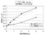
図4は温度40℃、湿度80%の過酷な状態で保存した上記構成のセンサで精製水を測定(ブランク値)した結果である。10回測定時の平均をプロットしたものであり、高温多湿の過酷な環境下においてもブランク値の上昇が抑制できることを示すものである。
【0018】
(表1)は血中グルコース濃度42〜600mg/dlにおける20回測定時のセンサ精度を比較したものである。センサ精度とは血液を毛細管内に吸引させた後、約25秒間試薬と血液中のグルコースとの反応を促進させた後、作用電極の接続端子2aと対電極の接続端子3a間に0.5Vの電圧を印加し、その5秒後に得られた電流値のバラツキ精度であり、本実施例センサの測定バラツキが従来センサに対し大幅に縮小軽減された事を示すものである。
【0019】
【表1】

図4および(表1)の結果から明らかなように、本実施例センサを用いる事で保存安定性に優れた、バラツキの少ない高感度なバイオセンサを実現することができる。なお、前記実施の形態では、血糖値測定用センサを例に挙げたが、同様な構成よりなるコレステロール、乳酸などの測定用センサにも同様な効果が得られるものである。
【0021】
【発明の効果】
以上のように本発明によれば、作用電極や対電極にピンホールや亀裂が生じたとしても、電子受容体である、例えばフェリシアン化カリウムと導電性リード部分に接することなく、さらに作用極においては銀などの金属よりなるのリード部の酸化電流を完全に防止することができ、高湿度環境下でも保存安定性に優れた、高品質のバイオセンサを提供できる。
【図面の簡単な説明】
【図1】本発明の一実施の形態における血糖値測定センサの製造工程を示す分解図
【図2】本発明の一実施の形態における血糖値測定センサと従来の血糖値測定センサの全血精度(CV値)の比較を示す図
【図3】従来の血糖値測定センサの製造工程を示す分解図
【図4】従来の血糖値測定センサの分解斜視図
【符号の説明】
1 基板
2,3 導電性リード
2a,3a 接続端子
2b,3b 先端部
4 作用電極
5 対電極
6 絶縁層
7 反応層
8 スペーサー
9 カバー
10 検体供給溝
11 空気孔[0001]
BACKGROUND OF THE INVENTION
The present invention relates to a biosensor for rapidly quantifying a substance to be measured in a sample liquid and a method for producing the same.
[0002]
[Prior art]
As a biosensor for measuring a specific measurement target substance in a sample liquid, for example, by measuring a current value obtained by a reaction between glucose in blood and a reagent such as glucose oxidase or potassium ferricyanide supported in the sensor There is what asks for blood sugar level. FIG. 2 is an exploded view showing a manufacturing process of such a conventional blood glucose level measuring sensor.
[0003]
A pair of conductive leads 2, 3 from the working electrode and the counter electrode to the measurement terminals 2a, 3a is formed on the film-like
[0004]
Next, an insulating layer 6 is formed by overprinting the insulating paste so as to expose the working
[0005]
After that, as shown in FIG. 3, the cover with the spacer 8 formed with the sample supply groove 10 having an opening at the tip is attached to the back surface so as to cover the
[0006]
When the sensor having the above configuration is attached to a measuring instrument and a blood sample to be measured is brought into contact with the opening of the specimen supply groove 10, a predetermined amount of sample is introduced into the
[0007]
[Problems to be solved by the invention]
In the case of the biosensor as described above, the working
[0008]
Further, the working electrode has a problem that the blank value increases due to the silver oxidation current, the CV deteriorates, and the sensor accuracy deteriorates. In addition, since the above problem has a greater influence in a high humidity environment, it is indispensable to store it in a dry state.
[0009]
[Means for Solving the Problems]
In order to solve the above problems, the biosensor of the present invention is characterized in that the reaction layer in contact with the electrodes is not provided above the conductive leads, even if the both Even if pinholes or cracks occur in both electrodes above the conductive lead part, the reaction layer is not provided in contact with both electrodes in that part, so potassium ferricyanide and the conductive lead part do not contact each other. is there. Furthermore, silver oxidation current can be prevented at the working electrode, and a high-quality biosensor can be provided even in a high humidity environment.
[0010]
DETAILED DESCRIPTION OF THE INVENTION
According to the first aspect of the present invention, a pair of conductive lead portions formed on an insulating substrate and a tip of one of the conductive lead portions partially overlap the conductive lead portion. A working electrode formed on the substrate, a counter electrode formed on the substrate so that a portion thereof overlaps the conductive lead portion at the tip of the other conductive lead portion, and both electrodes A reaction layer that reacts with the measurement object in the sample liquid formed so as to bridge both electrodes, and the measurement object obtained through the pair of conductive leads and the reaction layer In the biosensor that measures the content of the measurement object from the current value based on the reaction, the working electrode and the counter electrode that are formed on the conductive lead portion are covered and the conductive lead portion is overlapped. Not to expose working electrode and counter electrode The edge layer is provided, wherein the upper of the two conductive lead portions are biosensor characterized in that not be provided the reaction layer in contact with the two electrodes, the upper of the two electrodes of the two conductive lead portions Even if pinholes or cracks occur, the reaction layer is not provided in contact with both electrodes, and therefore, for example, potassium ferricyanide does not contact the conductive lead portion. Further, the working electrode can prevent oxidation current of the conductive lead portion made of silver or the like, and can provide a high-quality biosensor even in a high humidity environment.
[0011]
According to the fifth aspect of the present invention, a pair of conductive lead portions are formed on an insulating substrate, and a portion of the conductive lead portion is overlapped with the conductive lead portion. A counter electrode is formed so that a part of the electrode overlaps the conductive lead part at the tip of the other conductive lead part, and covers the part formed on the conductive lead part of both electrodes. A method for producing a biosensor comprising: forming an insulating layer, and then providing a reaction layer that reacts with an object to be measured in a sample liquid formed so as to bridge both electrodes on the electrodes. After forming the insulating layer so as to cover the portions formed on the conductive lead portions of both electrodes, a reaction layer is provided on the both electrodes. Even if it occurs, a reaction layer is provided in contact with both electrodes of that part. Since not, but it does not react layer and the conductive leads are in contact with each other.
[0012]
(Embodiment)
Hereinafter, a blood glucose level measurement sensor according to an embodiment of the present invention will be described with reference to FIG. FIG. 1 is an exploded view showing a manufacturing process of a blood glucose level measuring sensor, and the same parts as those in the conventional configuration shown in FIG.
[0013]
First, as in the prior art, the conductive leads 2 and 3 are formed on the
[0014]
An insulating layer 6 is formed by overprinting the insulating paste so that the working
[0015]
A predetermined
[0016]
Thereafter, the
[0017]
FIG. 4 shows the result of measuring purified water (blank value) with the sensor having the above-described configuration stored in a harsh state at a temperature of 40 ° C. and a humidity of 80%. The average of 10 measurements is plotted, and shows that the increase in the blank value can be suppressed even under a severe environment of high temperature and humidity.
[0018]
(Table 1) compares the sensor accuracy at the time of 20 measurement in blood glucose concentration 42-600 mg / dl. The sensor accuracy refers to 0.5 V between the connection terminal 2a of the working electrode and the connection terminal 3a of the counter electrode after the reaction between the reagent and glucose in the blood is promoted for about 25 seconds after the blood is sucked into the capillary tube. This is the variation accuracy of the current value obtained 5 seconds after application of the above voltage, and shows that the measurement variation of the sensor of this example is greatly reduced and reduced compared to the conventional sensor.
[0019]
[Table 1]
As is apparent from the results of FIG. 4 and (Table 1), a highly sensitive biosensor with excellent storage stability and less variation can be realized by using the sensor of this example. In the above-described embodiment, the blood glucose level measurement sensor is taken as an example. However, the same effect can be obtained with a sensor for measuring cholesterol, lactic acid and the like having the same configuration.
[0021]
【The invention's effect】
As described above, according to the present invention, even if a pinhole or a crack is generated in the working electrode or the counter electrode, the electron acceptor, for example, potassium ferricyanide and the conductive lead portion are not in contact with each other. It is possible to completely prevent the oxidation current of the lead portion made of a metal such as silver, and to provide a high-quality biosensor having excellent storage stability even in a high humidity environment.
[Brief description of the drawings]
FIG. 1 is an exploded view showing a manufacturing process of a blood glucose level measuring sensor according to an embodiment of the present invention. FIG. 2 is a whole blood accuracy of a blood glucose level measuring sensor according to an embodiment of the present invention and a conventional blood glucose level measuring sensor. FIG. 3 is an exploded view showing a manufacturing process of a conventional blood glucose level measuring sensor. FIG. 4 is an exploded perspective view of a conventional blood glucose level measuring sensor.
1
Claims (6)
Priority Applications (5)
| Application Number | Priority Date | Filing Date | Title |
|---|---|---|---|
| JP2000062855A JP3985417B2 (en) | 2000-03-08 | 2000-03-08 | Biosensor and manufacturing method thereof |
| US09/959,816 US6860978B2 (en) | 2000-03-08 | 2001-03-08 | Biosensor and method of producing the same |
| CNB018004741A CN1182388C (en) | 2000-03-08 | 2001-03-08 | Biosensor and manufacture thereof |
| EP01912188A EP1182451B1 (en) | 2000-03-08 | 2001-03-08 | Biosensor and method of producing the same |
| PCT/JP2001/001812 WO2001067081A1 (en) | 2000-03-08 | 2001-03-08 | Biosensor and method of producing the same |
Applications Claiming Priority (1)
| Application Number | Priority Date | Filing Date | Title |
|---|---|---|---|
| JP2000062855A JP3985417B2 (en) | 2000-03-08 | 2000-03-08 | Biosensor and manufacturing method thereof |
Publications (3)
| Publication Number | Publication Date |
|---|---|
| JP2001255297A JP2001255297A (en) | 2001-09-21 |
| JP2001255297A5 JP2001255297A5 (en) | 2007-04-12 |
| JP3985417B2 true JP3985417B2 (en) | 2007-10-03 |
Family
ID=18582811
Family Applications (1)
| Application Number | Title | Priority Date | Filing Date |
|---|---|---|---|
| JP2000062855A Expired - Lifetime JP3985417B2 (en) | 2000-03-08 | 2000-03-08 | Biosensor and manufacturing method thereof |
Country Status (5)
| Country | Link |
|---|---|
| US (1) | US6860978B2 (en) |
| EP (1) | EP1182451B1 (en) |
| JP (1) | JP3985417B2 (en) |
| CN (1) | CN1182388C (en) |
| WO (1) | WO2001067081A1 (en) |
Families Citing this family (19)
| Publication number | Priority date | Publication date | Assignee | Title |
|---|---|---|---|---|
| US8071384B2 (en) | 1997-12-22 | 2011-12-06 | Roche Diagnostics Operations, Inc. | Control and calibration solutions and methods for their use |
| US20050103624A1 (en) | 1999-10-04 | 2005-05-19 | Bhullar Raghbir S. | Biosensor and method of making |
| CA2467043C (en) * | 2001-11-16 | 2006-03-14 | North Carolina State University | Biomedical electrochemical sensor array and method of fabrication |
| GB0211449D0 (en) * | 2002-05-17 | 2002-06-26 | Oxford Biosensors Ltd | Analyte measurement |
| US7718439B2 (en) | 2003-06-20 | 2010-05-18 | Roche Diagnostics Operations, Inc. | System and method for coding information on a biosensor test strip |
| US8206565B2 (en) | 2003-06-20 | 2012-06-26 | Roche Diagnostics Operation, Inc. | System and method for coding information on a biosensor test strip |
| US7645373B2 (en) | 2003-06-20 | 2010-01-12 | Roche Diagnostic Operations, Inc. | System and method for coding information on a biosensor test strip |
| US7452457B2 (en) | 2003-06-20 | 2008-11-18 | Roche Diagnostics Operations, Inc. | System and method for analyte measurement using dose sufficiency electrodes |
| US8058077B2 (en) | 2003-06-20 | 2011-11-15 | Roche Diagnostics Operations, Inc. | Method for coding information on a biosensor test strip |
| US8071030B2 (en) * | 2003-06-20 | 2011-12-06 | Roche Diagnostics Operations, Inc. | Test strip with flared sample receiving chamber |
| US8148164B2 (en) | 2003-06-20 | 2012-04-03 | Roche Diagnostics Operations, Inc. | System and method for determining the concentration of an analyte in a sample fluid |
| PL1639352T3 (en) * | 2003-06-20 | 2019-03-29 | F. Hoffmann-La Roche Ag | Method and reagent for producing narrow, homogenous reagent strips |
| US8679853B2 (en) * | 2003-06-20 | 2014-03-25 | Roche Diagnostics Operations, Inc. | Biosensor with laser-sealed capillary space and method of making |
| US7645421B2 (en) | 2003-06-20 | 2010-01-12 | Roche Diagnostics Operations, Inc. | System and method for coding information on a biosensor test strip |
| US7569126B2 (en) | 2004-06-18 | 2009-08-04 | Roche Diagnostics Operations, Inc. | System and method for quality assurance of a biosensor test strip |
| US20110186428A1 (en) * | 2010-01-29 | 2011-08-04 | Roche Diagnostics Operations, Inc. | Electrode arrangements for biosensors |
| US10041901B2 (en) | 2013-03-15 | 2018-08-07 | Roche Diabetes Care, Inc. | Electrode configuration for a biosensor |
| US20150068893A1 (en) * | 2013-09-12 | 2015-03-12 | Joinsoon Medical Technology Co., Ltd. | Biosensor test strip for biosensor test device |
| CN109916983B (en) * | 2019-03-27 | 2020-04-10 | 南京腾森分析仪器有限公司 | Three-electrode system, electrochemical sensor and preparation method thereof, electrochemical workstation and application thereof |
Family Cites Families (5)
| Publication number | Priority date | Publication date | Assignee | Title |
|---|---|---|---|---|
| JP3084877B2 (en) * | 1992-01-21 | 2000-09-04 | 松下電器産業株式会社 | Manufacturing method of glucose sensor |
| KR970001146B1 (en) * | 1993-07-16 | 1997-01-29 | 엘지전자 주식회사 | Gas measuring bio-sensor and manufacturing method |
| JP3518932B2 (en) | 1995-06-23 | 2004-04-12 | 松下電器産業株式会社 | Biosensor |
| JP3460183B2 (en) * | 1996-12-24 | 2003-10-27 | 松下電器産業株式会社 | Biosensor |
| JP3505978B2 (en) * | 1997-09-26 | 2004-03-15 | Nok株式会社 | Biosensor |
-
2000
- 2000-03-08 JP JP2000062855A patent/JP3985417B2/en not_active Expired - Lifetime
-
2001
- 2001-03-08 WO PCT/JP2001/001812 patent/WO2001067081A1/en active Application Filing
- 2001-03-08 US US09/959,816 patent/US6860978B2/en not_active Expired - Lifetime
- 2001-03-08 EP EP01912188A patent/EP1182451B1/en not_active Expired - Lifetime
- 2001-03-08 CN CNB018004741A patent/CN1182388C/en not_active Expired - Lifetime
Also Published As
| Publication number | Publication date |
|---|---|
| EP1182451A1 (en) | 2002-02-27 |
| US6860978B2 (en) | 2005-03-01 |
| CN1182388C (en) | 2004-12-29 |
| EP1182451A4 (en) | 2003-06-25 |
| CN1364234A (en) | 2002-08-14 |
| EP1182451B1 (en) | 2011-08-03 |
| US20020179441A1 (en) | 2002-12-05 |
| WO2001067081A1 (en) | 2001-09-13 |
| JP2001255297A (en) | 2001-09-21 |
Similar Documents
| Publication | Publication Date | Title |
|---|---|---|
| JP3985417B2 (en) | Biosensor and manufacturing method thereof | |
| US7297248B2 (en) | Glucose strip sensor and glucose measurement method using the glucose strip sensor | |
| CN1163742C (en) | Biological sensor | |
| JP3971997B2 (en) | Biosensor | |
| JP4814952B2 (en) | Method for measuring hematocrit value of blood sample, method for measuring concentration of analyte in blood sample, sensor chip and sensor unit | |
| JP3595315B2 (en) | Thermal conductivity sensor | |
| AU2008279274B2 (en) | Electrochemical test strip | |
| JP4814953B2 (en) | Method for measuring hematocrit value of blood sample, method for measuring concentration of analyte in blood sample, sensor chip and sensor unit | |
| US5512159A (en) | Biosensor | |
| WO2008079731A1 (en) | Gel formation to reduce hematocrit sensitivity in electrochemical test | |
| WO2020094082A1 (en) | Potentiometric biosensor and detection method | |
| JP2960265B2 (en) | Biosensor and measurement method using the same | |
| JPH01156658A (en) | Biosensor | |
| JPH0648256B2 (en) | Biosensor | |
| JP4639465B2 (en) | Biosensor | |
| JP4352108B2 (en) | Substrate quantification method | |
| JPH0943189A (en) | Biosensor and method for determining substrate using it | |
| JP2548147B2 (en) | Biosensor | |
| US20100025239A1 (en) | Biosensor | |
| JP2727704B2 (en) | Biosensor manufacturing method | |
| JP3483930B2 (en) | Biosensor | |
| RU2713587C1 (en) | Biosensor, resistant to coffee stain effect | |
| KR102411089B1 (en) | A composition for bio-sensor and biosensor including the same | |
| AU2017204379B2 (en) | Electrochemical test strip | |
| JPH0610662B2 (en) | Biosensor |
Legal Events
| Date | Code | Title | Description |
|---|---|---|---|
| A521 | Written amendment |
Free format text: JAPANESE INTERMEDIATE CODE: A523 Effective date: 20070226 |
|
| A621 | Written request for application examination |
Free format text: JAPANESE INTERMEDIATE CODE: A621 Effective date: 20070226 |
|
| RD01 | Notification of change of attorney |
Free format text: JAPANESE INTERMEDIATE CODE: A7421 Effective date: 20070313 |
|
| TRDD | Decision of grant or rejection written | ||
| A01 | Written decision to grant a patent or to grant a registration (utility model) |
Free format text: JAPANESE INTERMEDIATE CODE: A01 Effective date: 20070619 |
|
| A61 | First payment of annual fees (during grant procedure) |
Free format text: JAPANESE INTERMEDIATE CODE: A61 Effective date: 20070702 |
|
| R151 | Written notification of patent or utility model registration |
Ref document number: 3985417 Country of ref document: JP Free format text: JAPANESE INTERMEDIATE CODE: R151 |
|
| FPAY | Renewal fee payment (event date is renewal date of database) |
Free format text: PAYMENT UNTIL: 20100720 Year of fee payment: 3 |
|
| FPAY | Renewal fee payment (event date is renewal date of database) |
Free format text: PAYMENT UNTIL: 20110720 Year of fee payment: 4 |
|
| FPAY | Renewal fee payment (event date is renewal date of database) |
Free format text: PAYMENT UNTIL: 20110720 Year of fee payment: 4 |
|
| FPAY | Renewal fee payment (event date is renewal date of database) |
Free format text: PAYMENT UNTIL: 20120720 Year of fee payment: 5 |
|
| FPAY | Renewal fee payment (event date is renewal date of database) |
Free format text: PAYMENT UNTIL: 20120720 Year of fee payment: 5 |
|
| FPAY | Renewal fee payment (event date is renewal date of database) |
Free format text: PAYMENT UNTIL: 20130720 Year of fee payment: 6 |
|
| S111 | Request for change of ownership or part of ownership |
Free format text: JAPANESE INTERMEDIATE CODE: R313113 |
|
| S533 | Written request for registration of change of name |
Free format text: JAPANESE INTERMEDIATE CODE: R313533 |
|
| R350 | Written notification of registration of transfer |
Free format text: JAPANESE INTERMEDIATE CODE: R350 |
|
| S111 | Request for change of ownership or part of ownership |
Free format text: JAPANESE INTERMEDIATE CODE: R313113 |
|
| R350 | Written notification of registration of transfer |
Free format text: JAPANESE INTERMEDIATE CODE: R350 |
|
| S111 | Request for change of ownership or part of ownership |
Free format text: JAPANESE INTERMEDIATE CODE: R313113 |
|
| R350 | Written notification of registration of transfer |
Free format text: JAPANESE INTERMEDIATE CODE: R350 |
|
| R250 | Receipt of annual fees |
Free format text: JAPANESE INTERMEDIATE CODE: R250 |
|
| R250 | Receipt of annual fees |
Free format text: JAPANESE INTERMEDIATE CODE: R250 |
|
| R250 | Receipt of annual fees |
Free format text: JAPANESE INTERMEDIATE CODE: R250 |
|
| S533 | Written request for registration of change of name |
Free format text: JAPANESE INTERMEDIATE CODE: R313533 |
|
| R350 | Written notification of registration of transfer |
Free format text: JAPANESE INTERMEDIATE CODE: R350 |
|
| R250 | Receipt of annual fees |
Free format text: JAPANESE INTERMEDIATE CODE: R250 |
|
| R250 | Receipt of annual fees |
Free format text: JAPANESE INTERMEDIATE CODE: R250 |
|
| EXPY | Cancellation because of completion of term |