JP3980064B2 - Pressure transducer with disposable dome - Google Patents
Pressure transducer with disposable dome Download PDFInfo
- Publication number
- JP3980064B2 JP3980064B2 JP53834797A JP53834797A JP3980064B2 JP 3980064 B2 JP3980064 B2 JP 3980064B2 JP 53834797 A JP53834797 A JP 53834797A JP 53834797 A JP53834797 A JP 53834797A JP 3980064 B2 JP3980064 B2 JP 3980064B2
- Authority
- JP
- Japan
- Prior art keywords
- disposable dome
- reusable
- dome
- disposable
- sensor
- Prior art date
- Legal status (The legal status is an assumption and is not a legal conclusion. Google has not performed a legal analysis and makes no representation as to the accuracy of the status listed.)
- Expired - Fee Related
Links
Images


Classifications
-
- A—HUMAN NECESSITIES
- A61—MEDICAL OR VETERINARY SCIENCE; HYGIENE
- A61B—DIAGNOSIS; SURGERY; IDENTIFICATION
- A61B5/00—Measuring for diagnostic purposes; Identification of persons
- A61B5/02—Detecting, measuring or recording pulse, heart rate, blood pressure or blood flow; Combined pulse/heart-rate/blood pressure determination; Evaluating a cardiovascular condition not otherwise provided for, e.g. using combinations of techniques provided for in this group with electrocardiography or electroauscultation; Heart catheters for measuring blood pressure
- A61B5/021—Measuring pressure in heart or blood vessels
- A61B5/0215—Measuring pressure in heart or blood vessels by means inserted into the body
-
- A—HUMAN NECESSITIES
- A61—MEDICAL OR VETERINARY SCIENCE; HYGIENE
- A61B—DIAGNOSIS; SURGERY; IDENTIFICATION
- A61B5/00—Measuring for diagnostic purposes; Identification of persons
- A61B5/03—Detecting, measuring or recording fluid pressure within the body other than blood pressure, e.g. cerebral pressure; Measuring pressure in body tissues or organs
-
- A—HUMAN NECESSITIES
- A61—MEDICAL OR VETERINARY SCIENCE; HYGIENE
- A61B—DIAGNOSIS; SURGERY; IDENTIFICATION
- A61B2562/00—Details of sensors; Constructional details of sensor housings or probes; Accessories for sensors
- A61B2562/02—Details of sensors specially adapted for in-vivo measurements
- A61B2562/0261—Strain gauges
-
- A—HUMAN NECESSITIES
- A61—MEDICAL OR VETERINARY SCIENCE; HYGIENE
- A61B—DIAGNOSIS; SURGERY; IDENTIFICATION
- A61B5/00—Measuring for diagnostic purposes; Identification of persons
- A61B5/03—Detecting, measuring or recording fluid pressure within the body other than blood pressure, e.g. cerebral pressure; Measuring pressure in body tissues or organs
- A61B5/031—Intracranial pressure
-
- A—HUMAN NECESSITIES
- A61—MEDICAL OR VETERINARY SCIENCE; HYGIENE
- A61B—DIAGNOSIS; SURGERY; IDENTIFICATION
- A61B5/00—Measuring for diagnostic purposes; Identification of persons
- A61B5/03—Detecting, measuring or recording fluid pressure within the body other than blood pressure, e.g. cerebral pressure; Measuring pressure in body tissues or organs
- A61B5/033—Uterine pressure
- A61B5/035—Intra-uterine probes therefor
Landscapes
- Health & Medical Sciences (AREA)
- Life Sciences & Earth Sciences (AREA)
- Molecular Biology (AREA)
- Surgery (AREA)
- Biophysics (AREA)
- Pathology (AREA)
- Engineering & Computer Science (AREA)
- Biomedical Technology (AREA)
- Heart & Thoracic Surgery (AREA)
- Medical Informatics (AREA)
- Cardiology (AREA)
- Physics & Mathematics (AREA)
- Animal Behavior & Ethology (AREA)
- General Health & Medical Sciences (AREA)
- Public Health (AREA)
- Veterinary Medicine (AREA)
- Hematology (AREA)
- Vascular Medicine (AREA)
- Physiology (AREA)
- Measuring Fluid Pressure (AREA)
- Measuring Pulse, Heart Rate, Blood Pressure Or Blood Flow (AREA)
Description
〔発明の背景〕
本発明は、医療用液圧トランスジューサ、特に、再使用可能な部品および一回使用の使い捨て部品を有する侵襲血圧測定のための液圧トランスジューサに関する。
1970年以来、外科手術および他の急性疾患に際して、血行力学的不安定性を生じる患者の診断および治療のために、生理学的な血圧モニターが広く用いられるようになった。セルジンガー(Seldinger)の経皮的穿刺技術を用いて、血管、カテーテル、動脈套管、中心静脈カテーテル、または肺動脈カテーテルが血管内に挿入される。穿刺傷を広げてカテーテルが血管内に挿入され、該カテーテルは生理食塩水を満たした圧力モニターライン、血圧トランスジューサ、加圧液供給源、滅菌液フラッシュ装置に取り付けられる。最後に、トランスジューサの電気的インターフェースケーブルが、電気的血圧増幅器および表示モニターに取り付けられる。このような装置は、一旦キャリブレートされると、心臓血管系内のカテーテル先端で定常的に変化する血圧レベルについての正確かつ最新の情報を与える。
同様に、急性脳損傷による頭蓋内圧上昇をモニターするために、液体を充填したカテーテルを脳の中に直接挿入するためのカテーテルおよび技術、並びに出産の際に子宮に挿入して、羊膜液圧の変化から収縮の強さおよび特徴をモニターするためのカテーテルおよび技術が開発されている。これら先行技術による多くの同様のトランスジューサシステムが、この測定適用の全範囲に加えて、他の生理学的モニターまたは生物学的液圧測定適用のために採用されている。
初期の典型的な従来技術装置には、トランスジューサアセンブリーを滅菌等張食塩水溶液でフラッシュおよび充填するための、入口ポートおよび出口ポートを備えた取り外し可能な(1回使用の使い捨て)ドームが含まれている。このドームは、フラッシュ液の中の気泡を観察および除去することができるように、ポリカーボネートのような透明なモールドプラスチック材料でできている。コール(Cole)に付与された米国特許第4,291,702号およびレイノルズ(Reynolds)に付与された米国特許第3,675,891号に記載されているようなフラッシュ装置は、このドームを通してカテーテルの中に食塩水の連続的な流れを与える目的で、典型的には該ドームの側部ポートに固定される。フラッシュ装置上の「迅速フラッシュ」弁を駆動して、ドームおよび/またはカテーテル内の血液の充填、脱気泡または洗浄のために、一時的に高い流速を選択してもよい。
初期の従来技術によるトランスジューサは、感圧性領域を形成する金属ダイアフラムを用いて、トランスジューサハウジングの外表面に作製された。このダイアフラムは、内部において、機械的プッシュロッドリンクアセンブリーおよび歪み検知器(例えばホイーストン橋構造に構築された非拘束ワイヤ歪みゲージ)に結合された。金属ダイアフラムの感圧性領域は、典型的には、単回使用ドームの適合表面上にある薄いポリカーボネートまたはニトリルゴムのダイアフラムによって、カテーテル内にフラッシュされる滅菌生理食塩水から隔離されている。このような使い捨てドームは、典型的には滅菌状態で供給され、患者への生物学的汚染の危険を回避するために、1回使用した後に廃棄される。これと合体して対をなす再使用可能なトランスジューサドーム(これは患者の血液に直接接触しない)は、頻繁にアルコールで拭い、または化学的滅菌剤の中に入れて、その後の使用のために新しい滅菌ドームに結合される。70年代の後期に、半導体歪みセンサを用いて幾つかの生理学的圧力トランスジューサシステムが開発されたが、やはり、機械的リンクおよび金属ダイアフラムを用いていた(例えば、Statham P50およびBentley M800)。歪み検知素子はシリコン梁であり、これはダイアフラムが曲げられたときに該シリコン梁に歪みが加わるように、トランスジューサ本体に結合される。これらの設計において、上記のホイーストン橋はシリコン梁に直接イオン注入され、また出力信号は、トランスジューサの電気的インターフェースコネクタに配置された個別の抵抗を用いてキャリブレートされた。他の点において、これらの「過渡的な」技術のトランスジューサは、典型的には、上記と同じ方法でカテーテル/マノメータ液システムに結合された。
80年代の初期には、米国特許第4,576,181号、同第4,291,702号、同第4,557,269号、同第4,683,984号、同第4,679,567号、同第5,402,495号、同第4,776,343号、同第5,097,841号に完全に記載されているように、センサチップの温度および梁間を補正するために、レーザトリミングされた厚膜抵抗ネットワークと組み合わせて用いる、エッチングされたダイアフラムを含むシリコンチップ製の改善された半導体歪みゲージを用いた、再使用不能な(使い捨ての)トランスジューサが開発された。更に、モトローラ社の薄膜「オンチップ」補正法(米国特許第4,465,075号参照)は、例えば米国特許第4,539,998号、同第4,679,567号および同第4,825,876号に完全に記載されているように、より小さい単純な使い捨てトランスジューサ設計の開発を可能にした。重要なこととして、これら全ての使い捨てトランスジューサ設計は、コールおよびコダマのそれを除いて、機械的リンクを廃止し、例えば米国特許第4,529,789号に記載されているようなシリコーンエラストマーまたは「シリコーンゲル」で構成された液圧カップリング媒体に切り替えたようである。チップを周囲の液体および蒸気から保護するために、半導体工業では既に一般的になっていたこれらエラストマーは、センサに対してより大きな機械的頑丈さおよび水力学的信号の伝達を与えると共に、チップと食塩水溶液との間の良好な電気的バリアを形成するために用いられる。医療用途では、ゲルがカテーテルフラッシュ溶液とトランスジューサチップとの間に並置されて、液圧信号を直接的にチップの一体的検知ダイアフラムに運ぶと共に、食塩水溶液の導電性および腐食効果からそれを電気的に隔離する。チップを含む全体のトランスジューサーアセンブリーは、内部の部品を再滅菌または再使用のために十分には洗浄できないので、典型的には、一回の使用後に廃棄されるべく販売される。
上記で述べた半導体歪みゲージおよびゲルカップリング媒体を用いた使い捨てトランスジューサ設計は、気泡の乱れまたは蓄積を伴わずに、滅菌生理食塩水が容易に充填される比較的直線的な液体チャンネルを与えるので、望ましいものである。更に、それは従来技術の再使用可能な設計のような、別の使い捨てドームをツイストオンで取り付けることを必要とせず、非常に頑丈であり、且つゲル圧力伝達媒体およびシリコンチップ微細加工センサの構造に起因して正確である。しかし、製造コストは依然高い。一つの最も高価な部品は、予めキャリブレートされた半導体チップおよび付属の配線であり、これらは典型的には一回の使用後に廃棄される。
従って、医療コストおよび医療廃棄物を更に減少させる目的で、現在の大容量シリコン微細加工およびチップキャリア製造技術により製造した安価な半導体歪みゲージセンサを用いた、再使用可能な生理学的圧力トランスジューサが必要とされている。ワラス(Wallace)(米国特許第4,610,256号)およびフランク(Frank)(国際出願PCT/US85/01957)は、シリコーン油を充填したトランスジューサ本体に取り付けた、厚膜を備えたシリコン歪みゲージセンサを用いる圧力トランスジューサを開示している。トランスジューサ本体の外部は、可撓性ダイアフラムで覆われた感圧性領域を有しており、該ダイアフラムは、シリコン油を満たした本体を介して液圧信号をチップセンサに伝え、また、圧力伝達液(夫々ゲルまたは油)で満たされた孔を介して、液圧信号を対向する外表面へと伝達する。これらの設計において、シリコンチップセンサおよび補正回路は、トランスジューサ本体の外側の対向表面に担持される。これら両方の例において、合体される使い捨てドームは、一回使用を目的とした従来技術による可撓性の滅菌隔離ダイアフラムを含んでいる。アダムス等(Adams, et al.)(米国特許第4,686,764号)は、薄膜を備えたチップセンサを含む、ゲルを充填した圧力トランスジューサ本体を開示している。このシリコンチップセンサは本体の内側に配置される。また、トランスジューサの外部の感圧性領域は、ポリアミドのような可撓性ポリマー膜からなっており、これは連結チャンネルを必要とすることなく、ゲルを介して液圧信号を直接センサに伝達する。フランク(米国特許第4,920,972号)は、これもまた本体の外部に配置され、且つゲルで満たされた傾斜孔を介して水力学的にダイアフラムに結合されたチップセンサを有する、ゲルを充填した本体を具備する血圧トランスジューサを開示している。この本体の反対側の感圧領域を覆うトランスジューサダイアフラムは、シリコーンゴムのような可撓性材料である。可撓性インターフェース膜を用いた従来技術の使い捨てドームは、滅菌食塩水をトランスジューサから隔離する。
しかし、これらの改良にもかかわらず、従来技術のトランスジューサは未だ一定の欠点を有している。これらのトランスジューサは、微細加工されたチップおよび配線を廃棄するコストが高いため製造が高価である。ワラスおよびフランクによって開示された従来技術による再使用可能なトランスジューサのダイアフラムは、容易に孔があき、圧力伝達媒体の漏出およびトランスジューサの故障を生じる。アダムスおよびフランクによって後で開示された再使用可能なトランスジューサは、水力学的カップリング媒体としてシリコーンゲルを使用することにより、機械的な頑丈さ(ruggedness)の著しい改善を与えるが、膜タイプのドームは入口ポートおよび出口ポートに比較して大きいので、ドーム内部の液体流路は複雑で、セットアップ、充填および脱気泡が困難であり、使用する前に取り付けて食塩水を充填しなければならない。実際に、ダイアフラムの縁部に隣接した鋭角のコーナー部に少量の気泡が付着して、変換された圧力信号のダイナミックな応答を低減する。
従って、現在の設計において、気泡が容易にトラップされる鋭角のコーナー部(例えば、ダイアフラムの近傍)が存在しない液体経路を用いた、再使用可能なトランスジューサに適用するための使い捨てドームを開発することが強く要望されている。気泡をシステムから除去するために必要な時間および困難性を最小限にするように、幾分直線的な液体充填経路を有する、再使用可能なトランスジューサのための使い捨てドーム構造を開発することも強く望まれている。また、センサーチップを、液圧伝達媒体と連通してトランスジューサ本体の内側に直接配置することにより、医療用の再使用可能なトランスジューサ設計の製造コストおよび複雑さを低減することが望まれている。最後に、従来の再使用タイプの装置には、医療従事者が、患者に付き添っている間に非滅菌部分に接触するのを防止するための物理的バリアが存在しない。非滅菌部分(再使用可能な部分)を、採血の際、並びにカテーテルおよびモニター装置の再調節およびキャリブレーションの際に、通常は医療従事者によって操作される滅菌部分から隔離するための手段を開発することが極めて望ましいであろう。本発明のこれらの目的および利点、並びに他の目的および利点は、添付の図面および後述する好ましい実施形態の説明から明らかになるであろう。
〔発明の概要〕
本発明の一つの側面に従えば、一般的に再使用可能な圧力トランスジューサ部分と、患者に対して滅菌的に露出される一回使用の使い捨てドームとを有する血圧モニター装置が提供される。この装置は、ハウジングを具備している。該ハウジングには、内部へ延びる液体流路を有する入口ポートおよび出口ポートが設けられている。該流路内のキャビティーは、可撓性の電気的隔離媒体および圧力伝達媒体によって、第一のチャンバーおよび第二のチャンバーに分割されている。この流路は、ハウジング内の第一のチャンバーと、入口ポートおよび出口ポートとの間の連絡を与える。
第一のチャンバーは隔離媒体を含んでおり、これは液体流路内の液体による液圧をトランスジューサに伝える。また、この隔離媒体は、液体流路と、以下で説明する再使用可能なトランスジューサ部分との間の電気的および生物学的バリアを形成する。
第二のチャンバーは、感圧性表面から離間された補正圧力センサを含んでおり、該圧力センサの一方の側は、トランスジューサハウジングの内表面にある通気孔と連通するように、密封して配置されている。この通気孔は、参照用の周囲空気圧を圧力センサの第一の側に与える。圧力伝達媒体は、感圧性表面からの液圧信号を圧力センサの第二の側に伝達するために、第二のチャンバー内に配置される。電気的導体が圧力センサに接続され、また外部の血圧モニターディスプレーに接続するために、ハウジングを通って延設されている。
ハウジングは、第一および第二の取り外し可能な固定部分に分割される。この第一の部分は、第一のチャンバー、隔離媒体、入口ポートおよび出口ポートを含んでおり、使用後に取り外して廃棄できるように適合される。第二の部分は、圧力センサ、導電体、および圧力伝達媒体を含む。一実施形態における第一の部分は、第二の部分における少なくとも一つの第二の相補的干渉係合表面に対して、取り外し可能な干渉「スナップ」嵌合を与えるために、少なくとも第一の干渉係合表面を有している。
好ましくは、隔離媒体はシリコーンゲルを有している。好ましい実施形態において、該隔離媒体および圧力伝達媒体は、相互に直接的または間接的な圧力伝達性で接触している。隔離媒体と圧力伝達媒体とが直接接触する場合、取り外しの際にゲルが付着および移動する危険を最小限に抑えるために、隔離媒体および圧力伝達媒体は、好ましくは異なった材料で作製される。或いは、第一の部分および第二の部分が取り外し可能に一緒に固定されるとき、ダイアフラムが隔離媒体を圧力伝達媒体から隔離するように設けられる。
本発明の他の側面に従えば、再使用可能なトランスジューサと共に使用するための、使い捨てドームを製造する方法が提供される。この方法は、両者の間に液体流路が延設された液体入口ポートおよび液体出口ポートを有するハウジングを形成するステップを具備する。隔離媒体は、液体流路に露出された第一の表面を有するように、このハウジングの中に配置される。隔離媒体は、液圧信号を、液体流の内の液体から隔離媒体を介して隔離媒体の第二の表面に伝えるための経路を与える。
ハウジングを再使用可能なトランスジューサ部分に取り外し自在に連結するために、当該技術において公知の相補的なネジ、スナップ嵌合、ルアー、干渉嵌合、圧縮嵌合等のような、解除可能なコネクタ構造がハウジングに設けられる。このハウジングと再使用可能なトランスジューサとの間の解除可能な連結とは、隔離媒体の第二の表面が、トランスジューサと液圧的に連通して配置されるものである。
好ましい実施形態では、この方法は、液圧信号を再使用可能なトランスジューサに伝える領域において、隔離媒体の第二の表面を凸形状に成形する追加のステップを具備する。この隔離媒体は、硬化可能なエラストマー前駆体を液体流路に接触させてハウジング内に配置して隔離媒体を形成し、該エラストマー前駆体をその場所で硬化させて隔離媒体を製造することによって形成することができる。
本発明の更なる側面に従えば、この方法は、患者内の血管と連通したカテーテルを有する患者を準備するステップを具備する。一回使用の使い捨てドームが提供されるが、該ドームはハウジングと、該ハウジングを通る流路と、ハウジング内において、前記流路とハウジング外に露出された圧力信号伝達表面との間に配置された液圧信号伝達媒体とを有する。
圧力トランスジューサであって、その上に圧力信号受容表面を有するトランスジューサが更に提供される。ハウジングの圧力信号伝達表面は、トランスジューサの圧力信号受容表面と圧力信号を伝達するように接触して、取り外し可能に配置される。流路は、カテーテルによって患者と液体流通し、血圧信号がトランスジューサによって検出されるように配置される。
また、再使用可能な圧力トランスジューサ装置と組み合わされ、または分離された形の、一回使用の使い捨てドームの更なる実施形態も開示される。
本発明の更なる特徴および利点は、添付の図面および請求の範囲を一緒に考慮すれば、以下の好ましい実施形態の詳細な説明から明らかになるであろう。
【図面の簡単な説明】
図1は、本発明によるトランスジューサ装置の一実施形態を示す、液体入口ポートおよび液体出口ポートの中心繊維沿った単純化された側断面図である。
図2は、トランスジューサ装置の第一の好ましい実施形態を示す、これも液体入口ポートおよび液体出口ポートの中心線に沿った断面図である。
図3は、フラッシュ装置、液体導管またはカテーテルに接続する前の、本発明によるトランスジューサドームの正面図である。
図4は、本発明によるトランスジューサ装置の平面図であり、該トランスジューサに取り付けられた図3のドームの側面図を示している。
図5は、トランスジューサを取り付けていない本発明によるトランスジューサドームの断面図である。その代わり、トランスジューサ/ドーム界面のゲルを予め設定された凸形状に硬化させる目的で、ゲルに外形を付すための「ダスト」キャップがドームに設置されている。
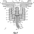
図6は、本発明の第二の好ましい実施形態の、入口ポートおよび出口ポートの中心線に沿った立面断面図である。
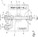
図7は、使い捨てドーム部分の第二の好ましい実施形態を示す平面図である。
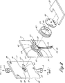
図8は、第三の好ましい実施形態を含む装置部分の分解斜視図であり、支持体プレートはトランスジューサ装置の再使用可能な部分でできており、また透明なモールド成形されたドーム部分は、取付けおよび保持構造および滅菌シールドを含んでいる。
図9は、本発明による液体フラッシュおよび単一カテーテルによる連続的圧力測定のための、典型的な圧力測定装置を模式的に示す説明図である。
図10は、使用者の前腕に装着された本発明の第四の実施形態を示す斜視図である。
図11は、本発明の第四の実施形態を示す断面図である。
図11Aは、本発明の第四の実施形態において、図11に矢印11Aで定義した部分をクローズアップして示す断面図である。
図11Bは、別の実施形態における一部分をクローズアップして示す断面図である。
図12は、本発明の第四の実施形態におけるドーム部分および再使用可能な部分を示す分解斜視図である。
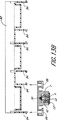
図13Aは、本発明と共に使用し得るivポール装着アダプターアセンブリーの断面図である。
図13Bは、図13Aに示したivポールアダプターの13B−13B線に沿った断面図、およびこれと対合する再使用可能なトランスジューサの水平断面図である。
〔詳細な説明〕
図1は、一般的に符号1で示される、圧力トランスジューサ装置の第一の実施形態を示している。この装置は二つの主要部分からなっており、夫々の主要部分には、それらを機械的に一緒に結合してトランスジューサ装置1を形成するための副部分が設けられている。第一の主要部分は再使用可能な部分であり、符号2で一般的に示されている。再使用可能部分2の中には導電体3がモールドされており、該導電体はワイヤ接合5を介して圧力センサチップ4へと電気信号を運び、また該圧力センサチップ4から電気信号を運ぶ。この導電体は絶縁ジャケット6を有しているので、ショックまたは短絡の危険を伴わずに、電気信号をトランスジューサ装置から遠隔圧力モニター(図示せず)へと運ぶことができる。
圧力トランスジューサ装置の第二の主要部分は使い捨てドーム7であり、該ドームは再使用可能部分2から取り外し可能であり、一般には一回使用を目的としている。液体入口ポート8および液体出口ポート9は、ドーム7の内部に位置する第一のチャンバー10と液体流通している。ドーム7は、圧力伝達性ではあるが、電気的および生物学的には隔離性であるゲル11を第一のチャンバー10の中に含んでおり、該ゲルの第一の側は、前記第一のチャンバーおよび前記入口ポートおよび出口ポートを満たすフラッシュ液と接触し、更に、該ゲルの第二の側は第二のチャンバー13を覆うダイアフラム12と接触する(13および14は何れも再使用可能部分2の一部である)。
ダイアフラム12は、再使用可能部分2の凹部表面を取り囲む隆起した環状リング14に結合される。該ダイアフラムは、第一のチャンバー10を満たす液体から、絶縁ゲル11を介して伝達される液圧信号に応答する。従って、ダイアフラム12は、この液圧信号を前記第二のチャンバー13に運び、次いで圧力伝達媒体15を介して圧力センサチップ4に伝えられる。圧力センサチップ4の圧力検知表面は、第二のチャンバー13の内部において圧力伝達媒体に露出されている。好ましくは、圧力センサチップ4のオンチップ回路は、予め定められたゲインおよび温度補正を含んでいる。図示の実施形態において、チップ4は、シリコーンゴムシール材17を用いて、通気孔16を覆って配置された第二のチャンバー13の床に密封して取り付けられており、該シール材17は、前記通気孔の端部を取り囲む密封リングの形で、その最上部をチップに近接させて、再使用可能部分2における凹部表面の底部に適用される。従来技術による再使用可能な医療用トランスジューサの教示とは反対に、この孔は周囲の空気で満たされており、患者の液圧測定を周囲圧に対して適切に参照するために、該センサにおける内部ダイアフラムの一方の側に対して連続的な周囲参照圧を与えることを目的としている。
ドームのネジ溝を施した円筒部分18は、二つの主要部分2および7を使用のために組み立てる際、再使用可能部分の係合ネジ部分19に脱着可能に螺合される。再使用可能部分2の外表面で軸方向に延設した複数の隆起リム20のような摩擦を増大する構造によって、圧力トランスジューサ装置1を組立および分解する際に再使用可能部分を把持し、これを入口ポートおよび出口ポート8および9に対して回転させることが可能になる。
図2は、符号1で一般的に示すトランスジューサ装置のもう一つの実施形態の断面図であり、これもまた、液体入口ポートおよび出口ポート8および9の中心に沿った断面で示されている。符号2で一般的に示す再使用可能部分は、部分21および22で形成されたハブを含んでいる。回転ナット24は、該ハブに形成された環状チャンネル内に回転可能に保持されている。この回転ナット24には、使い捨てドーム7の対応するネジと脱着可能に螺合するための、半径方向内側に向いた複数の環状ネジが設けられている。当業者には明らかなように、選択された構造が、媒体15および媒体11の間の界面を横切る圧力信号の十分な伝播を生じるのに十分な圧縮を与える限り、種々の他の脱着可能な保持構造の何れかを用いることができる。
再使用可能部分2は、更に、四つの絶縁された導電体16,17,28,29およびセンサ通気管30(これは断面で示されている)を収容したケーブルジャケット25を含んでいる。絶縁された導電体26および29は、再使用可能部分2の内部で終端する末端において絶縁被覆を除去されており、該導電体の細い末端はセンサハウジングピン31に半田付けされている。短絡を防止し、且つ液体耐性および腐蝕耐性を増大させるために、符号35で一般的に示される領域は、好ましくは、シリコーンゴムのようなポッティング化合物で満たされる。センサハウジングピン類は、その上端をセンサハウジング28の中にモールドされており、第二チャンバー13の内側で終端し、そこでワイヤ接合5により接続されている。ワイヤ接合は、当該技術で周知のように、圧力センサチップ4上のアルミニウムパッドまたは金パッドに接続される。従って、電気信号はワイヤ接合5を介して、圧力センサチップ5、センサハウジングピン31および絶縁された導電体26〜29へ、従って外部電気インターフェースコネクタ、圧力増幅器および測定表示装置(図示せず)へと運ばれ、またこれらから運ばれる。圧力センサチップ4は、通気管30と連通した通気孔16を覆って配置されたシリコンRTV17を用いて、第二チャンバー13の内部表面に密封して取り付けられ、こうして、通気孔16および通気管により形成された空気チャンネルは、患者の液圧測定値を周囲の大気圧と比較する(referencing)ために、センサ内部におけるダイアフラムの第一の側に対して、連続的な周囲参照を与える。第二のチャンバー13は、シリコーン油、或いは、好ましくは架橋ポリジメチルシロキサン(例えば、Rhone-Plulenc Visalox V-191から入手可能な二成分系シリコーンゲルであるプラチナキュア)のような圧力伝達媒体15で満たされる。
一般に符号7で示すトランスジューサ装置の使い捨てドーム部分は、透明なモールド部分34と、該モールド部分と一体に形成され且つモールド部分内の第一のチャンバー10と液体流通する入口および出口液体チャンネル8および9と、前記第一のチャンバー内の凹部に配置された感圧性であるが電気的および生物学的に絶縁性のゲル11と、ネジ付き支持体プレート32と、回転ルアーナット(rotating luer nuts)33とからなっている。この回転ルアーナットは、液体伝達管および生体内に挿入された液体を満たしたカテーテルに対して、入口ポートおよび出口ポートを確実に接続する手段を提供する。透明なモールド部分34は、第一のチャンバー10または前記液体チャンネル入口および出口8および9に液体を満たす際に、存在する泡または血液を容易に観察でき、また液体充填セットアッププロセスの際に除去できるように、好ましくは、ポリカーボネートのような透明プラスチック材料のモールドである。
使い捨てドーム部分7の製造に際して、透明モールド部分34はネジ付き支持体プレート32に超音波融着され、または溶剤もしくは接着剤で結合される。こうして形成された下方部分(第一のチャンバー10)には、未硬化の隔離ゲルを充填し、該ゲルを硬化し且つ外形与えることにより隔離ゲルを形成する(これについては、図5の説明に関連して十分に説明する)。
隔離ゲル11は、前記液体と前記ダイアフラム12との間に配置され、従って、前記液体(これは侵襲カテーテルと液体連通する)とダイアフラム12(これは再使用可能部分2の感圧性表面を与える)との間に電気的および生物学的バリアを提供する。ダイアフラム12は、再使用可能部分2から離間した第二チャンバー13の上方延設部を形成する環状リングに対して、密封状態で取り付けられる。更なる機械的な丈夫さおよび液体耐性をを与えるために、ダイアフラムは、好ましくは加圧成形されたポリマー若しくはゴム製のシートであり、再使用可能部分2の全頂面を横切って広がっており、ここで使い捨てドーム部分7と接触している。該ダイアフラムは、好ましくは厚さ2〜10ミルのポリイソプレン製であるが、302ステンレス鋼、ニトリルもしくはブチレンゴム、高密度ポリエチレン、デュポン製のマイラー、テフロン、またはCapton若しくはUpalonの商品名で販売されているポリアミドシートを使用することもできる。
或いは、前記隔離媒体および圧力伝達製媒体として、この二つの材料が実際の使用における正常な接触時間では相互に結合しないように、二つの異なる材料を選択してもよい。このような場合、圧力伝達媒体は一体的なダイアフラム手段を形成してもよい。この別の実施形態のダイアフラム12は、チャンバー13に架橋ポリジメチルシロキサンのような圧力伝達媒体を充填し、続いてプライマーを含有しない単一成分のDowシリコーン接着剤(カタログ番号3-6611)トップ層を充填することによって実証されている。硬化すると、このシリコーン接着剤は圧力伝達媒体に粘着して、丈夫な外側スキン(これは一体的な膜である)を形成する。この硬化した接着剤は、組成および硬さにおいて隔離ゲル11とは十分に異なっているので、隔離ゲル11と直接接触させて使用することができる。銀のような蒸着可能な金属を真空で電子ビーム蒸着し、硬く且つ異なった表面(これは液圧信号の伝達に効果的である)を形成するような、圧力伝達媒体の追加の表面修飾もまた可能である。
上述したように、第二のチャンバー13は、好ましくは、シリコーンゲルのような圧力伝達媒体15で満たされる。ダイアフラム12が光透過性の材料から選ばれるときは、当該技術で周知のように、シリコーンゲルは、圧力伝達媒体を光不透過性にするカーボンブラック粉末のような充填材を含むことができる。こうして、光が第二のチャンバーに入り、圧力トランスジューサチップ4による発生した圧力の読み取りに影響するのが防止される。
臨床的使用において、圧力トランスジューサ装置1は、再使用可能部分2および使い捨てドーム部分7から容易に組み立てられる。再使用可能部分は、その感圧性ダイアフラムを最も前方に向けて、ネジ付き支持プレート32の中に形成された凹部の中に入れられる。再使用部分が侵入するとき、回転ナット24は支持体プレートの合体ネジに係合する。こうして、回転ナットは何回も回転され、ダイアフラム12を完全に侵入させて、隔離媒体11と直接接触させる。この侵入プロセスに際して、幾らかの空気が、前記使用可能部分および使い捨てドーム部分の合体部に形成されるクレバスの中へと逃れる。図5に関連してより完全に説明するが、ダイアフラム12は、最初にダイアフラムの中央で隔離媒体11と接触するので、隔離ゲル媒体は制御された均一な方法で、第一のチャンバー10の中に流れて変形し、前記ダイアフラムと前記隔離媒体との間に残留する空気を完全に排除する。該残留空気は、前記再使用可能部分22と支持体プレート32の凹部との間のクレバスを通して逃散する。ダイアフラム12が回転して、隔離ゲル11との滑らかで且つ均一な接触を乱す可能性を防止するために、再使用可能な部分22の合体部を受け入れる支持体プレート32内部の凹部は、任意に、丸くない形状に構成することができる。或いは、案内チャンネルおよび合体キー溝を、問題の合体部分の中にモールドして、ハブ部分22をゲル11に対して回転可能にリンクさせることができる。
図3には、本発明による第一の好ましい実施形態の使い捨てドーム部分7の正面図が示されており、これはドームの透明なモールド部分34、ネジ付き支持体プレート32の頂面、入口ポート8、出口ポート9、第一のチャンバー10、回転ルアーナット33、ルアーナット上の隆起リム20、支持体ランド36ダイアフラム12(ドームおよび隔離媒体11の透明部分を通して見える)、液体入口チャンネル37、液体出口チャンネル38、支持体プレート38のネジ付き部分の隠れた図、自己接着ラベルを取り付けるためのモールドランド領域39,40を示している。
支持体プレート32は、着色されたポリカーボネート、スチレンまたはABSのような不透明材料でモールド成形されている。入口および出口の液体チャンネル37および38、並びに回転ルアーナット33を含む透明モールド部分34は、支持体プレートの頂面に固定されて、第一のチャンバー10を形成する。支持体ランド36は、入口チャンネル37および出口チャンネル38を取り囲む透明モールドのルーメンが支持体プレートの側部を出るときに、これらのために追加の機械的支持を提供する。支持体プレート32の外観を改善するために、該表面には、好ましくは特定のテクスチャーが与えられる。ランド領域39および40は、その境界に沿った小さい隆起または溝、並びにその中の滑らかな表面仕上げによって定義してもよい。圧力トランスジューサ装置を臨床的にセットアップする際に、これらランド領域にラベルを貼って、圧力トランスジューサ装置に特定の測定機能および本発明と共に使用されるカテーテルを指定し、および/または製品の商品名ラベルを配置してもよい。
図3から、本発明によるトランスジューサ装置は、適切な装着ブラケットを用いれば、入口および出口チャンネル37および38を水平または垂直の何れの配置にしても使用できることが容易に分かる。ICUまたは手術室で容易に充填および脱気泡するためには、図9でより完全に記載するように、液体チャンネルを垂直位置に配置するのが好ましいことが多い。しかし、各トランスジューサの間に配置され、複数のカテーテルの連結および充填に適合させる連結ストップコックを用いて、幾つかのトランスジューサが一緒に連結されるようなカテーテル実験室では、入口および出口チャンネル37、38を水平向きに配置する方が望ましいことが多い。本発明は、この両方の用途に適合させることを意図している。
図4は第一の好ましい実施形態の平面図であり、ネジ付き支持体ブラケット32、符号2によって一般的に示される再使用可能部分、回転ナット24、リブ20、ケーブルジャケット25、絶縁された導電体26〜29、通気管30、回転ルアーナット23、出口ポート9、およびドームの透明モールド部分34、および支持体ブラケットの支持体ランド部分36を示している。
この図から分かるように、モールドされた支持体ブラケット32は、使い捨てドーム7の透明モールド部分と再使用可能な部分2との間に、効果的に物理的バリアを与える。何等かの滅菌配管、カテーテル、またはフラッシュ装置部品は使い捨てドームに設置することを意図したものであり、モールドされた支持体ブラケットは、これらの部品と再使用可能部分2との間に配置される滅菌シールドとして働く。この図では再使用可能部分2の下方に延出しているように見えるネジ付き支持体ブラケットの下方延設部は、当該技術において周知のように(例えば、図9を参照のこと)、標準的なポール装着マニホルドクランプを用いて、ivポールに固定することを意図している。ネジ付き支持体ブラケット32の最も後ろの位置に取り付けられた適切なクランプブラケットを用いて、トランスジューサ装置がivポール上に設置されたら、配管部分、フラッシュ部分、およびカテーテル部分は、再使用可能部分2に接触することなく、滅菌技術を用いて使い捨てドーム部分7に組み立てられる。ネジ付き支持体ブラケット32の前方表面は更に、使い捨てドーム部分7に取り付ける滅菌部品を操作する際に、不注意により再使用可能部分と接触するのを防止する。
図5には、隔離媒体11を形成するプロセスを示すための、本発明による使い捨てドーム部分の立面断面図が示されている。使い捨てドーム部分7の製造に際して、透明モールド部分34は、ネジ付き支持体プレート32に超音波融着され、または溶媒若しくは接着剤で結合される。適合するように形成されたダストキャップ41は、液体が逃げるのを防止するために、ネジ付き支持体ブラケット32の底部端を覆って挿入される。ダストキャップ41は、先に説明したように、ダイアフラムが接触するように設計されたネジ付き支持体プレートの開口部内に、ゲルの凸形状を与える。こうして形成された容器の下方部分に未硬化のシリコーンゲルを充填する。該ゲルは、隔離ゲル11を形成するように輪郭を付けた形状に硬化される。隔離ゲル11は、架橋ポリジメチルシロキサン、例えばプラチナキュア(Rhone-Plulencからカタログ#Visalox V-191として入手可能な二成分系シリコーンゲル)のような、圧力伝達性であるが電気的および生物学的には絶縁性の媒体である。ダストキャップと共にゲルがその場所で硬化したら、使い捨てドーム部分7は包装の中に配置され、滅菌包装された副部分を生じるように処理される。医療従事者が再使用可能部分上で組み立てるために包装開くと、ダストキャップは除去および廃棄され、再使用可能な部分との係合のために、より詳細には、ダイアフラム12または他の接触表面(ダイアフラムが削除されまたは一体に形成された実施形態の場合)との係合のために提示される、滅菌された隔離媒体11の外部凸表面が残される。
ダストキャップ41は、好ましくは、硬化するシリコーンゲルに接着しない圧力成形可能なプラスチック材料、例えばポリエチレン若しくは可塑化されたPVCで作製される。出すとキャップの側部は、支持体プレートのネジと干渉嵌合(interference fit)を作るように設計された溝を有している。ネジ付き支持体ブラケット12に対するダストキャップのより緊密な密封を与えるために、ダストキャップには、支持体プレートのネジと接触する部分に任意にネジを形成することができる。
隔離媒体11に対するダイアフラム12の合体性を更に改善するために、ゲルの硬化後に何時でもダストキャップを取り外して、シリコーン油の滴を凸状ゲル表面の中央に塗布することができる。このステップは、例えば、硬化後で且つ滅菌のために包装する前に、ダストキャップを簡単に取り外し、油をダストキャップ内で形成された凸表面に塗布し、次いでダストキャップを再度取り付けて、上記のように包装および滅菌のプロセスに戻すことによって行うことができる。
図6には、本発明の更に好ましい実施形態1が、液体入口ポートおよび液体出口ポート8および9の中心線に沿った断面で示されている。この図において、設置された導電体27および28は図示されていないが、それらは図示された導電体26および29と同じ一般的な方向、配置、およびコースに従うと理解されるべきである。また、第一の実施形態の回転ルアーナット33は、透明なモールドドーム部分34の一体的部分を形成する固定されたルアー容器で置き換えられている。当業者には明らかなように、従来の種々の液体ライン留め具の何れを用いてもよい。
図6の実施形態は、ダイアフラムに対して、その活性な圧力応答領域に亘って一般的に球形状が与えられている点を除き、第一の実施形態と同用にして動作する。更に、それ自身のオンチップ薄膜補正を含まない、チップ4のゼロ補正および距離補正を行う厚膜抵抗器キャリブレーションワーク42を配置するために、領域35にはより大きなスペースが与えられている。この実施形態において、厚膜ネットワークはチップのキャリアとして作用する。このキャリアは、接着剤で結合されて第二のチャンバー13の床を形成する。圧力伝達媒体15は該チャンバーを満たしており、第一のチャンバー10内の隔離媒体11および液体と連通した圧力応答性ダイアフラム12からの液圧信号を、シリコンチップセンサ4の第一の側へと伝達する。通気管30は、周囲圧参照をチップセンサの第二の側に与える。厚膜ネットワーク42は、好ましくは、シリコーンゴムの環状リング17を使用して、再使用可能部分22に取り付けられる。センサハウジングピン31は、センサハウジング22の中に取り付けられ、また小さい半田づけされたリードまたはワイヤ接合が、前記センサハウジングピンから厚膜基体へ、または直接的にチップヘと延びている。こうして、厚膜基体またはチップに対するケーブルおよび絶縁導電体26、29からの過大な歪みの負荷は回避される。或いは、絶縁された導電体26,29は、これら導電体を厚膜基体に直接半田付けできるように十分細いゲージとすることができる。或いは、厚膜基体42に対してピンがバネ接触を形成するようにして、絶縁された導体が、ピンの一部を形成する絶縁貫通接点と接触するようにすることができる。電気接点手段におけるこのような変形例は、当該技術における専門家には明かであろう。
図7は、本発明による使い捨てドーム部分7の実施形態の正面図である。ここでは、使い捨てドーム部分の液体出口経路38に三方停止コック43および補助的液体チャンネル44が加えられており、次に説明する更に便利なゼロ点調整、キャリブレーション、および採血のために、補助出口ポート45における滅菌液体容積または圧力の便利な操作を提供している。
使い捨てドーム部分7は、典型的にはその入口ポート8で、滅菌食塩水制御流の供給源であるフラッシュ装置に接続される。このフラッシュ装置は、セットアップの際に液体入口チャンネル37、第一のチャンバー10、液体出口チャンネル38、そして最終的には取り付けられた配管およびカテーテルを満たすために用いられる。三方停止コック43を前記液体出口チャンネルに挿入することにより、幾つかの他の機能を実行することができる。停止コック43は、補助チャンネル44と連通した停止コックのポートを「オフ」または閉塞位置に回した正常な圧力測定位置で示されている。この位置において、正常な液体-液体の流通は、カテーテルと第一チャンバー10との間で可能になる。カテーテルのための、滅菌フラッシュ溶液の連続的な遅い流れもまた、入口ポートを通してフラッシュ装置により供給される。(別の構成において、停止コックは入口ポートに配置することができ、フラッシュ装置は、出口ポート9からカテーテルに導く圧力管と直列に配置することができる。)
停止コックのハンドル上の「オフ指示器」が第一のチャンバー10の向きに回転されているとき、カテーテルの圧力モニターおよびフラッシュは停止され、カテーテル中の滅菌溶液は補助液体チャンネル44および補助ポート45と連通している。容量が約10ccのシリンジが補助ポート45に取り付けられ、典型的には、そのハンドルを完全に押し下げて、その内部液体容積を最小にする。シリンジハンドルを引き上げ、停止コックのオフ矢印をトランスジューサに向ければ、医療従事者は、カテーテルおよび連結ラインから10ccの液体を引き上げることにより、カテーテルに近接したHEMOLOC TM部位52において、「無針」採血のために血液をカテーテルおよび配管の中に引き出すことができる(図9)。HEMOLOC TM部位で少量の血液サンプルを採取した後、シリンジのハンドルを押し下げることによって、カテーテルおよび配管の中に残留する全ての血液を患者に注射還流することができる。この無針でかつ血液を漏らさないサンプリング技術は、不注意による針刺し(「スティック」)、即ち、医療従事者の傷、または患者に近接した位置での血液漏れによる医療従事者への感染の危険を減少させるので、大きな利点である。
更に、ハンドル上のオフ指示器が出口ポート9を向くようにストップコックのハンドルを回すと、圧力モニターおよびカテーテルのフラッシュは停止し、フラッシュ装置(例えば、熱希釈心拍出量注射に用いるためのもの)を用いて補助液体チャンネルおよびシリンジに滅菌食塩水が充填される。また、停止コックをこの位置に保持したまま、一時的にシリンジを取り外すことによって、チャンバー10内の液体およびシリコンチップセンサは、圧力測定系をゼロ調整位置またはキャリブレートするために、大気圧または参照圧力に露出される。上記方法に従って、補助ポートがトランスジューサのゼロ調整のために使用されるとき、医療従事者は、圧力測定系を患者の現在の位置および姿勢に対して最も正確にキャリブレートするために、典型的には、補助ポート45の垂直レベルを中間の高さに配置するであろう。
従って、ストップコック43、補助液体チャンネル44および補助ポート45の追加によって、圧力測定系をキャリブレートする容易で且つ正確な方法に加えて、患者の血液を洗浄または漏出せずに、実験室分析のための採血を行う改善された方法という明確な利点が与えられる。
図8は、第三の好ましい実施形態を構成する部品の等角図(isometric view)を示している。この実施形態において、支持体プレート56は、再使用可能部分2の一部でできている。再使用可能部分は、先ずセンサーハウジング25を、支持体プレート56の裏側にある隆起リムで囲まれた凹部領域の中に接合することによって組み立てられる。センサハウジングの第二のチャンバーは、隆起リムおよびダイアフラムと共に支持体プレートの孔を通され、これらの先頭部分は透明モールド部分34の適合孔59に整列されて、当該プレートの前面に配置される。
絶縁された導電体26〜29は、センサハウジングピン31に半田付けされ、支持体プレート内のチャンネルを通して外部電気ケーブル25へと導かれる。支持体プレート、センサハウジング、および絶縁された導電体を組み立てた後に、好ましくは、漏出および短絡を排除するために、支持体プレート裏面の凹部領域にRTVシリコーンゴムまたはエポキシをポッティングする一方、周囲の空気圧に露出されるように全てのシール材を通気孔から遠ざける。次いで、クランプリング63が、センサハウジングの中心軸回りに回転できるように、隆起リム60を覆って緩く嵌合した状態で配置される。このクランプリングは、その内壁に湾曲部(ramp)を含んでおり、これは、使い捨て部分の突起57が嵌合孔61に挿入されて、リングが時計方向に回転されたときに、突起57と合体係合するように設計される。従って、クランプリングおよび突起は、上記のようにして操作するときに、再使用可能部分および使い捨て部分を一緒に引っ張り、且つ保持するための係合および保持手段である。
次いで、自己接着ラベル66がクランプリングのリム64に付着され、再使用可能ブラケット22が支持体プレートの水平溝に結合されて、再使用可能部分の組立が完了する。
隆起した密封エッジ67に囲まれた嵌合孔59は、透明モールド部分34の背面側にある前記第一チャンバーの後方部分に形成され、また隔離媒体11の後方凸状部分は嵌合孔59の中に見ることができる。一般に符号34で示す透明なモールドされたドーム部分は、二つの突起57および三つの隆起パッド58を含んでいる。上記で説明したように、これらの突起は、再使用可能部分と合体および係合する手段を形成する。係合の際、隆起パッド58は、滅菌シールド部分68の上部および底部を支持体プレート21から若干離間させる。その結果、再使用可能部分が突起57およびクランプリング63の係合機構によって一緒に引っ張られたときに、水平中心にある二つの嵌合片は、孔59および密封エッジ67の領域に第一の接触を生じて、液圧信号伝達経路の確実で再現可能な密封を保証する。
滅菌シールド68は、ゼロ調整停止コックを操作するとき、またはドームのシースルー部分を覗くときに、医療従事者をが再使用可能部分に接触するのを防止する。コストの理由で、それはポリカーボネートのような薄いプラスチックで作製され、好ましくは、入口液体チャンネルおよび出口液体チャンネル、並びに透明モールド部分が成形されるのと同じ工程で、一段階モールドプロセスによりモールドされる。
この第三の好ましい実施形態は、使い捨て部分に使用するプラスチック材料を最小限にする上において、最初の二つの好ましい実施形態を凌駕する利点を有している。この特徴は、病院および供給業者にとって、廃棄プラスチック物質の過剰使用に関連した制限および高コストが存在する市場では特に有利であり得る。
図9は、本発明に従って、単一カテーテルをモニターおよび維持する完全な圧力測定システムの一つの形態を示す等角図(isometric view)であり、溶液が満たされたプラスチックivバッグを含む加圧フラッシュ溶液46、圧力カットオフ、膨張弁、および圧力ゲージ、滴下チャンバーを組み込んだiv投与セット47、トランスジューサ装置1の入口ポート8に接続されたフラッシュ装置48、円筒部を覆う滅菌保護ブーツおよびハンドルを組み込んだ、補助ポート45に接続される10ccの使い捨てシリンジ49、電気的インターフェースコネクタ54に接続されたケーブル25内の絶縁された導電体(該コネクタは、圧力測定および表示システム55と電気的に導通している)、ivVポールに取り付けられ、クランプネジを用いてトランスジューサ装置1の後部を前記クランプの溝内に機械的にクランプするマニホルドポール装着クランプ50、出口ポート9をHEMOLOCTMポート52に接続する圧力配管(該HEMOLOC TMは、生体における問題の生理学的圧力測定に適合したカテーテル53へと導く液体配管に接続される)を含んでいる。
図10を参照すると、本発明の第四の実施形態の斜視図が示されている。図示のように、この第四の実施形態の圧力トランスジューサ装置1は、入口液体ポート8および出口液体ポート9を含んでいる。この実施形態の圧力トランスジューサ装置1は、ベルクロ帯68のような固定バンドによって患者の前腕に装着される。
図11、図11Aおよび図11Bを参照すると、そこには圧力トランスジューサ装置1の第四の実施形態の断面図が示されている。この特別な実施形態は、本発明に従って、使い捨てドーム7と再使用可能部分2との間の「スナップ嵌合」を利用している。先の実施形態の効果に加えて、この構成は、好ましくは、夫々の患者に圧力トランスジューサ装置1を適用した後に廃棄しなければならない滅菌プラスチック物質の量を最小限にする。更に、第四の実施形態のこの構成は、患者およびスタッフの両者の生物学的汚染の危険を最小限にする。
図11および図11Aは、組み立てた状態、即ち、使い捨てドーム7を再使用可能部分2にスナップ嵌合した状態での、再使用可能部分2および使い捨てドーム7を図示している。使い捨てドーム7は、滑らかな壁で仕切られた、好ましくは実質的に直線的な液体充填経路および中央の液体チャンバー10を含んでいる。液体チャンバー10は、生物学的隔離媒体11と連通しており、且つ好ましくは、その表面によって部分的に定義される。隔離媒体11は、圧力を伝達するようにダイアフラム12と接触しており、環状密封エッジ67によって前記ダイアフラムに対して密封されている。隔離媒体11は、厚さが略10ミルで且つ70デュロメータの医療等級シリコーンゴムで構成することができる。望ましいことに、70デュロメータのシリコーンは、トランスジューサベース2からドームを取り外すときに、ステンシルバリアの破損およびカテーテル液の汚染もしくは漏出を防止するのに十分な引き裂き耐性を与えるようである。シリコーン製O-リング構造体90は、好ましくは媒体11の外縁に形成されて、ダイアフラムの確実な装着手段を与える。こうして、媒体11は使い捨てドーム7の一部を形成し、また圧力伝達媒体15と圧力伝達性の接触をしていて、先に説明したように、その接触表面に一体的なダイアフラム12を含んでいる。
或いは、図11Bに示すように、O-リング90を含む媒体11は、把持および保持構造体91によって固定されてもよい。液体経路の平滑さを改善して、気泡のトラップを回避するために、隔離媒体11は少量のシリコーンゲルを含んでいてもよい。上記で説明したように、該ゲルは、シリコーンゴム製の予め形成されたダイアフラムの頂面に滴下して硬化させればよい。好ましくは、予め形成されたダイアフラム周囲(使い捨てドーム7が接触する)の全ての鋭角コーナー部の内側をこのゲル73で形成して、著しく滑らかで且つ本質的に真っ直ぐな内部液体経路を与える一方、カテーテル液に追加の電気的生物学的絶縁を与えるのが有利であろう。
媒体11によって提示される液圧信号に応答して、厚さ10ミルのニトリルゴム製ダイアフラム12は、この液圧信号を第二のチャンバー13に伝え、圧力伝達媒体15を介してセンサチップ14に伝える。図11Bの実施形態において、ダイアフラム12に隣接したチャンバー13の断面積は、チップ4に隣接したチャンバー13の断面積よりも大きい。圧力媒体15は、シリコーンゲルを含んでいてもよい。チップ4は、厚膜ネットワークのようなシリコンチップキャリアおよびシリコーン接着剤シール材17によって、第二のチャンバー13の床に取り付けられる。ワイヤ接合リード5は、圧力信号をチップ4からケーブル25に運び、最終的には電気的インターフェースコネクタ54(図10)に運ぶ。センサ通気管30は、通気孔16を介して、参照大気圧を圧力センサチップ4の一方の側に運ぶ。センサ通気管30は、コネクタ54の基端部で換気され(図12参照)、厚膜基体42の裏側を出るときに、その先端で通気孔16に接続される。
この実施形態の特別の利点は、スナップオン取付け構造74を使用して、トランスジューサの使い捨て部分7が迅速かつ容易に再使用可能部分2に取り付けられ、且つ取り外されることである。好ましくは、この取付け構造74は一以上の、好ましくは二つの圧縮可能な突起76からなり、これは使い捨てドーム7の反対側に予めモールドされる。一組の受容タブ78が再使用可能部分2に形成される。突起76は、使い捨てドーム7を再使用可能部分2に取り外し可能に固定するために、タブ78と係合するように構成される。使用者は、使い捨てドーム7を再使用可能部分2から外すために、上方に引っ張りながら、位置69で突起を把持して圧縮する。ドーム7を再度取り付けるためには、使用者は単に、突起76がタブ78と係合してドーム7をその場にロックするように、ドーム7を再使用可能部分の上に押すだけでよい。
一般に、再使用可能部分2と使い捨てドーム7との間のスナップ嵌合構造は、所望の製品特性に応じて、干渉嵌合、ラチェット型構造、摩擦嵌合等に基づくことができる。典型的な製品において、ドーム7の又はこれに接続された少なくとも一つの干渉表面92は、再使用可能部分2の又はこれに取り付けられた少なくとも一つの対応する表面と、取り外し可能に係合する。図11に示した実施形態において、干渉表面92は、タブ78の相補的表面と係合した突起76上に見られる。該干渉表面92は、好ましくは干渉表面92を再使用可能部分2の相補的表面に向けて付勢する可撓性アーム94により、ドーム7に接続されている。従って、アーム94によって生じる付勢力に打ち勝つことにより、干渉表面92を再使用可能部分2の孔86を通って延出させることが可能になる。圧縮力を解除すると、アーム94の付勢力により、干渉表面92が再使用可能部分2の対応する表面と係合することが可能になる。上記の特性を有する一つの2成分ロック構造を使用できるが、好ましくは、圧力トランスジューサの二つの部品を確実に一緒に装着するために、図11に示したような二つの対向するロック構造体が用いられるであろう。
種々の取り外し可能なスナップ嵌合型の如何なる構造であっても、その選択された構造が、媒体11および15間のインターフェースを横切る圧力の十分な広がりを生じさせるのに十分な圧縮を与える限り、その何れを用いてもよい。
図11の実施形態において、生物学的隔離媒体11およびダイアフラム12は両者とも、最も厚い縦方向の断面部分をその外周に沿って配置して、好ましくは軟質の弾性材料で作製される。二つの突起67は、使い捨てドーム7が再使用可能部分2に対して前進するときに、二つの弾性材料を圧縮する。突起67と弾性材料との間に生じた圧縮によって、好ましくは、突起76上の係合表面を、再使用可能部分におけるタブ78の相補的表面に強固に係合させて保持するためのバネ力が与えられる。従って、このスナップ型嵌合は、再使用可能部分2に強固に取り付けられた使い捨てドーム7を十分なバネ力で保持し、この二つの部分の間に優れた液圧信号伝達性を与える。液体経路から遠くに延出する厚い外側保持セクションをもった二つの弾性材料の向きは、使い捨てドーム7を通る実質的に真っ直ぐな液体経路の特別な利益を与えるが、これは、再使用可能なトランスジューサ用の使い捨てドームの分野では独特のものである。これまで、再使用可能なトランスジューサのための使い捨てドームは、その隔離媒体(即ちダイアフラム)の最も厚い縦方向の保持部分を、圧力伝達表面から上に向けて設計されいるので、ドームを通る湾曲した又は段差のある流路が必要とされ、これは屡々望ましくない気泡のトラップを生じている。従って、ここに記載した本発明の種々の実施形態における隔離媒体11の新規な形状は、その使用の容易さが、完全な使い捨てトランスジューサ設計に匹敵するという特別の利点を与える。
図12は、第四の実施形態による圧力トランスジューサ1の斜視図を示しており、ここでは、再使用可能部分2および使い捨てドーム7は相互に分解されている。図示のように、滅菌シース80は管形状を有し、好ましくは、薄いポリエチレン製または他のプラスチック製の可撓性チューブで作製されている。この滅菌シース80は、使用に際してケーブル25および電気的コネクタ54を収容する。使い捨てドーム7、ベルクロ帯68、およびシース80を含むスナップ嵌合型圧力トランスジューサ構造の一定の部分は、好ましくは滅菌状態で供給され、また組み立てるときにトランスジューサ1の再使用可能部分2を完全に覆うように作製される。臨床的使用において、再使用可能部分2は清浄であることは必要であろうが、滅菌的である必要はない。この実施形態は、患者を移送するとき、または医師がカテーテルおよびチューブの長さを短くして忠実性の高い血圧記録を得たいときに屡々有利であるように、トランスジューサ装置1を患者に直接装着することを意図している。図11に示すように、再使用可能なハウジング2の外側スロットに帯の末端を通し、次いで患者の前腕または他の外肢に巻き付けることにより、トランスジューサ装置1を患者の手首または前腕に確実に取り付けるために、ベルクロ帯68が用いられる。
図13Aおよび図13Bは、本発明による一以上の第四の実施形態をivポールマニフォルドホルダーアセンブリーに装着するために用いることができる、アダプターアクセサリーを示している。図13Bに示すように、複数のアクセサリー突起84が、アダプターアクセサリー82から外側に延出している。アクセサリー突起84は、好ましくは二つのセットに配列され、トランスジューサ装置1の再使用可能部分の孔86と合体するように構成されている。これによって、再使用可能部分2を、ivポールまたは他の便利な支持体構造に対して、アダプターアクセサリー82によるスナップ嵌合で取り外し可能に装着することが可能になる。従って、本発明の第四の実施形態は、患者から迅速に取り外して、図13Aおよび図13Bに示したアダプターアセンブリー82を用いてivポールマニホルドホルダーアセンブリーに搭載することができる。
このオプションは、患者が、トランスジューサをモニター装置に近いより固定された位置に置くことが望まれる集中治療に到達したときに、特に有利であり得る。このアクセサリーを使用するためには、患者の手首に配置されていたベルクロ帯68を解き、トランスジューサ装置を患者の腕から取り外す。この処置に際し、好ましくは滅菌技術が維持され、また、好ましくはトランスジューサが患者の血圧信号をモニターし続ける。次いで、ベルクロ帯68がトランスジューサ装置1の背面から引き抜かれ、トランスジューサ装置の残りの部分、即ち、使い捨てドーム7と共に組み立てられていた再使用可能部分2は、待機しているアダプタアセンブリー82(図9に示したタイプのivポールマニホルドホルダ50に予め取り付けられている)にスナップ嵌合される。
こうして、図10〜図13に示した実施形態は、一緒にスナップする本発明の特徴に基づいて、種々の臨床状況への容易な対応を可能にする。本発明はまた、臨床スタッフが高価な再滅菌技術に頼ることなく、トランスジューサ装置1の再使用可能部分2を容易に再使用できるので、病院のための経済的節約を提供する。また、各適用の後に廃棄される1回使用の滅菌材料を製造するコストは、一体的なセンサーチップをもった一回使用で完全に使い捨てのトランスジューサの製造コストよりも著しく低い。
好ましい実施形態に関して本発明を開示してきたが、当業者は、後述の請求範囲の範囲内において更なる改変がなされ得ることを理解するであろう。従って、本発明の範囲は上記に開示したものに制限されるものではなく、後述の請求範囲に照らして全体的に決定されるべきものである。BACKGROUND OF THE INVENTION
The present invention relates to a medical hydraulic transducer, and more particularly to a hydraulic transducer for invasive blood pressure measurement having reusable parts and single use disposable parts.
Since 1970, physiological blood pressure monitors have become widely used for the diagnosis and treatment of patients with hemodynamic instability during surgery and other acute diseases. Using a Seldinger percutaneous puncture technique, a blood vessel, catheter, arterial cannula, central venous catheter, or pulmonary artery catheter is inserted into the blood vessel. The catheter is inserted into the blood vessel with the puncture wound widened, and the catheter is attached to a pressure monitor line filled with physiological saline, a blood pressure transducer, a pressurized fluid supply source, and a sterile fluid flush device. Finally, the transducer electrical interface cable is attached to the electrical blood pressure amplifier and display monitor. Such a device, once calibrated, provides accurate and up-to-date information about blood pressure levels that steadily change at the catheter tip in the cardiovascular system.
Similarly, in order to monitor the increase in intracranial pressure due to acute brain injury, catheters and techniques for inserting a fluid-filled catheter directly into the brain, and insertion into the uterus during childbirth, Catheters and techniques have been developed to monitor the strength and characteristics of contractions from changes. Many similar transducer systems according to these prior art have been employed for other physiological monitoring or biological hydraulic measurement applications in addition to the full range of this measurement application.
Early typical prior art devices included a removable (single-use disposable) dome with inlet and outlet ports for flushing and filling the transducer assembly with sterile isotonic saline solution. ing. The dome is made of a transparent molded plastic material such as polycarbonate so that air bubbles in the flash liquid can be observed and removed. A flush device, such as that described in US Pat. No. 4,291,702 to Cole and US Pat. No. 3,675,891 to Reynolds, provides continuous saline solution through the dome and into the catheter. For the purpose of providing a smooth flow, it is typically secured to the side port of the dome. A “rapid flush” valve on the flash device may be driven to temporarily select a high flow rate for filling, degassing or flushing blood in the dome and / or catheter.
Early prior art transducers were fabricated on the outer surface of the transducer housing using a metal diaphragm that formed a pressure sensitive region. The diaphragm was coupled internally to a mechanical push rod link assembly and strain detector (eg, an unconstrained wire strain gauge built on a Wheatstone bridge structure). The pressure sensitive area of the metal diaphragm is typically isolated from sterile saline that is flushed into the catheter by a thin polycarbonate or nitrile rubber diaphragm on the conformable surface of the single use dome. Such disposable domes are typically supplied in a sterile state and are discarded after a single use to avoid the risk of biological contamination to the patient. Paired with this, a reusable transducer dome (which does not come into direct contact with the patient's blood) is frequently wiped with alcohol or placed in a chemical sterilant for subsequent use. Coupled to a new sterile dome. In the late 70s, several physiological pressure transducer systems were developed using semiconductor strain sensors, but again using mechanical links and metal diaphragms (eg, Statham P50 and Bentley M800). The strain sensing element is a silicon beam, which is coupled to the transducer body such that when the diaphragm is bent, the silicon beam is strained. In these designs, the Wheatstone bridge was ion-implanted directly into the silicon beam, and the output signal was calibrated using a separate resistor located at the electrical interface connector of the transducer. In other respects, these “transient” technology transducers were typically coupled to the catheter / manometer fluid system in the same manner as described above.
In the early 80s, U.S. Pat.Nos. As described, an improved semiconductor strain gauge made of silicon chip with an etched diaphragm used in combination with a laser-trimmed thick film resistor network to compensate for sensor chip temperature and beam spacing. A non-reusable (disposable) transducer was developed. Further, Motorola's thin film “on-chip” correction method (see US Pat. No. 4,465,075) is smaller, as described fully in, for example, US Pat. Nos. 4,539,998, 4,679,567, and 4,825,876. Enables the development of simple disposable transducer designs. Importantly, all these disposable transducer designs, except those of Cole and Kodama, eliminate the mechanical link and are made with silicone elastomers or “silicone gels” as described, for example, in US Pat. No. 4,529,789. It seems to have switched to the configured hydraulic coupling medium. These elastomers, which are already common in the semiconductor industry to protect the chip from ambient liquids and vapors, provide greater mechanical robustness and hydraulic signal transmission to the sensor, Used to form a good electrical barrier with saline solution. In medical applications, the gel is juxtaposed between the catheter flush solution and the transducer tip to carry the hydraulic signal directly to the integral sensing diaphragm of the tip and to electrically remove it from the conductive and corrosive effects of the saline solution. Isolate. The entire transducer assembly, including the chip, is typically sold for disposal after a single use because the internal components cannot be cleaned sufficiently for re-sterilization or reuse.
The disposable transducer design using the semiconductor strain gauge and gel coupling media described above provides a relatively linear liquid channel that is easily filled with sterile saline without turbulence or accumulation of bubbles. Is desirable. In addition, it does not require a separate disposable dome to be twisted on, as in the prior art reusable design, is very rugged, and has a gel pressure transmission medium and silicon chip microfabricated sensor construction. Due to accuracy. However, manufacturing costs are still high. One most expensive component is a pre-calibrated semiconductor chip and attached wiring, which are typically discarded after a single use.
Therefore, there is a need for a reusable physiological pressure transducer that uses an inexpensive semiconductor strain gauge sensor manufactured by current high-capacity silicon microfabrication and chip carrier manufacturing technology to further reduce medical costs and medical waste It is said that. Wallace (US Pat. No. 4,610,256) and Frank (international application PCT / US85 / 01957) pressure using a silicon strain gauge sensor with a thick film attached to a transducer body filled with silicone oil. A transducer is disclosed. The outside of the transducer body has a pressure-sensitive region covered with a flexible diaphragm. The diaphragm transmits a hydraulic pressure signal to the chip sensor via the body filled with silicon oil, and the pressure transmission liquid. A hydraulic signal is transmitted to the opposing outer surface through holes filled with (respectively gel or oil). In these designs, the silicon chip sensor and correction circuit are carried on opposing surfaces outside the transducer body. In both these examples, the combined disposable dome includes a prior art flexible sterile isolation diaphragm intended for single use. Adams, et al. (US Pat. No. 4,686,764) discloses a gel-filled pressure transducer body including a chip sensor with a thin film. This silicon chip sensor is disposed inside the main body. Also, the pressure sensitive area outside the transducer consists of a flexible polymer film such as polyamide, which transmits the hydraulic signal directly to the sensor through the gel without the need for a connecting channel. Frank (US Pat. No. 4,920,972) is a gel-filled body that has a chip sensor that is also located outside the body and is hydraulically coupled to the diaphragm through an inclined hole filled with gel. A blood pressure transducer comprising: The transducer diaphragm that covers the pressure sensitive area on the opposite side of the body is a flexible material such as silicone rubber. Prior art disposable domes with flexible interface membranes isolate sterile saline from the transducer.
However, despite these improvements, prior art transducers still have certain drawbacks. These transducers are expensive to manufacture because of the high cost of discarding microfabricated chips and wiring. Prior art reusable transducer diaphragms disclosed by Wallace and Frank easily perforate, causing pressure transmission media leakage and transducer failure. The reusable transducer later disclosed by Adams and Frank provides a significant improvement in mechanical ruggedness by using silicone gel as the hydraulic coupling medium, but a membrane-type dome Is larger than the inlet and outlet ports, the liquid flow path inside the dome is complex and difficult to set up, fill and degas, and must be installed and filled with saline before use. In practice, a small amount of air bubbles adhere to the sharp corners adjacent to the diaphragm edges, reducing the dynamic response of the converted pressure signal.
Thus, in the current design, to develop a disposable dome for application to a reusable transducer using a liquid path that does not have sharp corners (eg, near the diaphragm) where bubbles can be easily trapped. Is strongly demanded. It is also strong to develop a disposable dome structure for a reusable transducer with a somewhat linear liquid filling path so as to minimize the time and difficulty required to remove bubbles from the system. It is desired. It is also desirable to reduce the manufacturing cost and complexity of medical reusable transducer designs by placing the sensor chip directly inside the transducer body in communication with the hydraulic transmission medium. Finally, conventional reusable devices do not have a physical barrier to prevent medical personnel from contacting non-sterile parts while attending to a patient. Developed means to isolate non-sterile parts (reusable parts) from sterilized parts normally manipulated by medical personnel during blood collection and during readjustment and calibration of catheters and monitoring devices It would be highly desirable to do so. These and other objects and advantages of the present invention will become apparent from the accompanying drawings and the following description of the preferred embodiments.
[Summary of the Invention]
In accordance with one aspect of the present invention, a blood pressure monitoring device is provided having a generally reusable pressure transducer portion and a single use disposable dome that is sterilized to the patient. The device includes a housing. The housing is provided with an inlet port and an outlet port having a liquid flow path extending inward. The cavity in the flow path is divided into a first chamber and a second chamber by a flexible electrical isolation medium and a pressure transmission medium. This flow path provides communication between the first chamber in the housing and the inlet and outlet ports.
The first chamber contains an isolation medium that conveys the fluid pressure due to the liquid in the liquid flow path to the transducer. This isolation medium also forms an electrical and biological barrier between the liquid flow path and the reusable transducer portion described below.
The second chamber includes a compensation pressure sensor spaced from the pressure sensitive surface, and one side of the pressure sensor is hermetically disposed to communicate with a vent in the inner surface of the transducer housing. ing. This vent provides a reference ambient air pressure to the first side of the pressure sensor. A pressure transmission medium is disposed in the second chamber for transmitting a hydraulic signal from the pressure sensitive surface to the second side of the pressure sensor. An electrical conductor is connected to the pressure sensor and extends through the housing for connection to an external blood pressure monitor display.
The housing is divided into first and second removable fixed portions. This first portion includes a first chamber, an isolation medium, an inlet port and an outlet port and is adapted to be removed and discarded after use. The second part includes a pressure sensor, a conductor, and a pressure transmission medium. The first portion in one embodiment includes at least a first interference to provide a removable interference “snap” fit to at least one second complementary interference engagement surface in the second portion. It has an engagement surface.
Preferably, the isolation medium comprises a silicone gel. In a preferred embodiment, the isolation medium and the pressure transmission medium are in contact with each other with direct or indirect pressure transmission. If the isolation medium and the pressure transmission medium are in direct contact, the isolation medium and the pressure transmission medium are preferably made of different materials in order to minimize the risk of gel attachment and movement upon removal. Alternatively, a diaphragm is provided to isolate the isolation medium from the pressure transmission medium when the first part and the second part are removably secured together.
In accordance with another aspect of the present invention, a method for manufacturing a disposable dome for use with a reusable transducer is provided. The method includes forming a housing having a liquid inlet port and a liquid outlet port with a liquid flow path extending therebetween. The isolation medium is disposed in the housing so as to have a first surface exposed to the liquid flow path. The isolation medium provides a path for transmitting a hydraulic signal from the liquid in the liquid stream through the isolation medium to the second surface of the isolation medium.
Releasable connector structures such as complementary screws, snap fits, lures, interference fits, compression fits, etc. known in the art to removably connect the housing to the reusable transducer portion Is provided in the housing. The releasable connection between the housing and the reusable transducer is such that the second surface of the isolation medium is placed in hydraulic communication with the transducer.
In a preferred embodiment, the method comprises the additional step of shaping the second surface of the isolation medium into a convex shape in the region that transmits the hydraulic signal to the reusable transducer. This isolation medium is formed by placing a curable elastomeric precursor in contact with a liquid flow path and placing it in a housing to form the isolation medium, and curing the elastomeric precursor in place to produce the isolation medium. can do.
According to a further aspect of the present invention, the method includes providing a patient having a catheter in communication with a blood vessel in the patient. A single use disposable dome is provided, the dome being disposed between the housing, a flow path through the housing, and within the housing between the flow path and a pressure signal transmitting surface exposed outside the housing. And a hydraulic pressure signal transmission medium.
There is further provided a pressure transducer having a pressure signal receiving surface thereon. The pressure signal transmitting surface of the housing is removably disposed in contact with the pressure signal receiving surface of the transducer to transmit the pressure signal. The flow path is arranged such that fluid is in fluid communication with the patient via the catheter and the blood pressure signal is detected by the transducer.
Also disclosed are further embodiments of a single use disposable dome in combination with or separated from a reusable pressure transducer device.
Additional features and advantages of the present invention will become apparent from the following detailed description of the preferred embodiments, when considered in conjunction with the accompanying drawings and claims.
[Brief description of the drawings]
FIG. 1 is a simplified cross-sectional side view along the central fiber of a liquid inlet port and a liquid outlet port showing one embodiment of a transducer device according to the present invention.
FIG. 2 shows a first preferred embodiment of the transducer device, which is also a cross-sectional view along the center line of the liquid inlet port and the liquid outlet port.
FIG. 3 is a front view of a transducer dome according to the present invention prior to connection to a flash device, liquid conduit or catheter.
FIG. 4 is a plan view of a transducer device according to the present invention, showing a side view of the dome of FIG. 3 attached to the transducer.
FIG. 5 is a cross-sectional view of a transducer dome according to the present invention without a transducer attached. Instead, a “dust” cap is placed on the dome to outline the gel for the purpose of curing the transducer / dome interface gel to a preset convex shape.
FIG. 6 is an elevational cross-sectional view along the centerline of the inlet and outlet ports of the second preferred embodiment of the present invention.
FIG. 7 is a plan view showing a second preferred embodiment of the disposable dome portion.
FIG. 8 is an exploded perspective view of the device portion including the third preferred embodiment, wherein the support plate is made of a reusable portion of the transducer device and the transparent molded dome portion is mounted And includes a retention structure and a sterilization shield.
FIG. 9 is an explanatory view schematically showing a typical pressure measuring device for continuous pressure measurement using a liquid flush and a single catheter according to the present invention.
FIG. 10 is a perspective view showing a fourth embodiment of the present invention attached to the user's forearm.
FIG. 11 is a cross-sectional view showing a fourth embodiment of the present invention.
FIG. 11A is a cross-sectional view showing, in close-up, the portion defined by the
FIG. 11B is a cross-sectional view showing a part close-up in another embodiment.
FIG. 12 is an exploded perspective view showing a dome portion and a reusable portion according to the fourth embodiment of the present invention.
FIG. 13A is a cross-sectional view of an iv pole mounting adapter assembly that may be used with the present invention.
13B is a cross-sectional view of the iv pole adapter shown in FIG. 13A along
[Detailed explanation]
FIG. 1 shows a first embodiment of a pressure transducer device, generally designated 1. This device consists of two main parts, each of which has a sub-part for mechanically joining them together to form the transducer device 1. The first major part is a reusable part and is generally indicated by reference numeral 2. A conductor 3 is molded in the reusable part 2, which carries an electrical signal to and from the
The second main part of the pressure transducer device is a disposable dome 7, which is removable from the reusable part 2 and is generally intended for a single use. The
The
The dome threaded
FIG. 2 is a cross-sectional view of another embodiment of the transducer device, generally designated 1, also shown in cross-section along the center of the liquid inlet and
The reusable part 2 further includes a
The disposable dome portion of the transducer device, generally indicated by reference numeral 7, comprises a
In manufacturing the disposable dome portion 7, the
The
Alternatively, two different materials may be selected as the isolating medium and pressure transmission medium so that the two materials do not bond to each other during normal contact times in actual use. In such a case, the pressure transmission medium may form an integral diaphragm means. The
As mentioned above, the
In clinical use, the pressure transducer device 1 is easily assembled from a reusable part 2 and a disposable dome part 7. The reusable part is placed in a recess formed in the threaded
FIG. 3 shows a front view of a first preferred embodiment disposable dome portion 7 according to the present invention which includes a
The
From FIG. 3, it can be readily seen that the transducer apparatus according to the present invention can be used with either the horizontal or vertical arrangement of the inlet and
FIG. 4 is a plan view of the first preferred embodiment, showing a threaded
As can be seen from this figure, the molded
FIG. 5 shows an elevational cross-sectional view of a disposable dome portion according to the present invention to illustrate the process of forming the
The dust cap 41 is preferably made of a pressure moldable plastic material that does not adhere to the cured silicone gel, such as polyethylene or plasticized PVC. Once out, the sides of the cap have grooves designed to create an interference fit with the support plate screws. In order to provide a tighter seal of the dust cap to the threaded
To further improve the integrity of the
In FIG. 6, a further preferred embodiment 1 of the present invention is shown in a section along the center line of the liquid inlet and
The embodiment of FIG. 6 operates in the same manner as the first embodiment, except that the diaphragm is generally given a spherical shape over its active pressure response region. In addition, more space is provided in
FIG. 7 is a front view of an embodiment of a disposable dome portion 7 according to the present invention. Here, a three-way stop cock 43 and an auxiliary
The disposable dome portion 7 is typically connected at its
When the “off indicator” on the stopcock handle is rotated in the direction of the
In addition, when the stopcock handle is turned so that the off indicator on the handle is directed to the exit port 9, the pressure monitor and catheter flush are stopped and the flush device (eg, for use in thermodiluted cardiac output injection). The auxiliary liquid channel and syringe are filled with sterile saline solution. Also, by temporarily removing the syringe while holding the stop cock in this position, the liquid in the
Thus, the addition of stopcock 43, auxiliary
FIG. 8 shows an isometric view of the parts making up the third preferred embodiment. In this embodiment, the support plate 56 is made of part of the reusable part 2. The reusable part is assembled by first joining the
Insulated conductors 26-29 are soldered to
The self-
A
The
This third preferred embodiment has the advantage over the first two preferred embodiments in minimizing the plastic material used in the disposable part. This feature can be particularly advantageous for hospitals and suppliers in markets where there are limitations and high costs associated with overuse of waste plastic materials.
FIG. 9 is an isometric view showing one form of a complete pressure measurement system for monitoring and maintaining a single catheter in accordance with the present invention, a pressurized flash comprising a plastic iv bag filled with solution. Incorporates
Referring to FIG. 10, a perspective view of the fourth embodiment of the present invention is shown. As shown, the pressure transducer device 1 of the fourth embodiment includes an
Referring to FIGS. 11, 11A and 11B, there is shown a cross-sectional view of a fourth embodiment of the pressure transducer device 1. This particular embodiment utilizes a “snap fit” between the disposable dome 7 and the reusable part 2 in accordance with the present invention. In addition to the effects of the previous embodiments, this configuration preferably minimizes the amount of sterile plastic material that must be discarded after applying the pressure transducer device 1 to each patient. Furthermore, this configuration of the fourth embodiment minimizes the risk of biological contamination of both patients and staff.
11 and 11A illustrate the reusable part 2 and the disposable dome 7 in the assembled state, ie, with the disposable dome 7 snapped onto the reusable part 2. The disposable dome 7 includes a preferably substantially straight liquid filling path and a central
Alternatively, as shown in FIG. 11B, the medium 11 including the O-
In response to the hydraulic pressure signal presented by the medium 11, the 10 mil thick
A particular advantage of this embodiment is that using the snap-on
In general, the snap fit structure between the reusable part 2 and the disposable dome 7 can be based on interference fit, ratchet type, friction fit, etc., depending on the desired product characteristics. In a typical product, at least one interference surface 92 of or connected to the dome 7 removably engages at least one corresponding surface of the reusable part 2 or attached thereto. In the embodiment shown in FIG. 11, the interference surface 92 is seen on the
As long as the structure of the various removable snap-fit types provides sufficient compression to produce sufficient spread of pressure across the interface between
In the embodiment of FIG. 11, both the
FIG. 12 shows a perspective view of a pressure transducer 1 according to a fourth embodiment, in which the reusable part 2 and the disposable dome 7 are disassembled from each other. As shown, the
13A and 13B illustrate an adapter accessory that can be used to attach one or more fourth embodiments according to the present invention to an iv pole manifold holder assembly. As shown in FIG. 13B, a plurality of
This option may be particularly advantageous when the patient reaches intensive care where it is desired to place the transducer in a more fixed position near the monitoring device. In order to use this accessory, the
Thus, the embodiments shown in FIGS. 10-13 allow easy adaptation to various clinical situations based on the features of the present invention that snap together. The present invention also provides economic savings for hospitals because clinical staff can easily reuse the reusable part 2 of the transducer device 1 without resorting to expensive re-sterilization techniques. Also, the cost of producing a single use sterilized material that is discarded after each application is significantly lower than the cost of producing a single use, fully disposable transducer with an integrated sensor chip.
While the invention has been disclosed in terms of preferred embodiments, those skilled in the art will recognize that further modifications may be made within the scope of the claims that follow. Accordingly, the scope of the invention is not limited to that disclosed above, but should be determined entirely in light of the claims that follow.
Claims (30)
前記使い捨てドームは、前記再使用可能なセンサと係合及び取外し可能に且つ1回使用した後で使い捨て可能に構成され、電気的及び生物学的に絶縁性の隔離用シリコーンゴムを含んでおり、この隔離用シリコーンゴムは、流体で満たされた前記使い捨てドーム内のチャンバーから前記再使用可能なセンサの上に配置された感圧ダイアフラムに液圧信号を伝達し、
前記使い捨てドームは、インターロック構造部を使用して前記再使用可能なセンサに取付け可能であり、前記インターロック構造部は、前記使い捨てドームを前記感圧ダイアフラムに対して垂直方向に延びる軸線に沿って前記再使用可能なセンサに対して移動させる、前記使い捨てドームと前記再使用可能なセンサとの間の係合及び取外し動作を規制し、前記感圧ダイアフラムと前記隔離用シリコーンゴムとの係合及び取外し動作は、非摩擦的であり且つねじれがなく、
更に、前記使い捨てドームは、それと再使用可能なセンサとの間の係合及び取外し動作が前記感圧ダイアフラムに対して全体的に垂直方向に行われ且つ前記感圧ダイアフラムと実質的に平行な方向における前記使い捨てドームと前記再使用可能なセンサとの間の回転動作を防止するための構造を有し、前記感圧ダイアフラムは、軟質の弾性材料で作製され、
前記使い捨てドームは、入口ポートと出口ポートを有し、前記チャンバーは、前記入口ポートと前記出口ポートとの間に配置され、
前記使い捨てドームは、更に、前記入口ポートから前記チャンバーを通って前記出口ポートまで延びる直線的な流体流路を有し、この直線的な流体流路は、流路全体にわたって実質的に真直ぐに延び、その結果、前記入口ポートから前記使い捨てドームに流入して前記チャンバーを満たすように前記直線的な流体流路に沿って移動する流体は、前記入口ポートと前記出口ポートとの間の流れ方向を変化させない乱流しか発生させず、且つ、気泡の蓄積を回避する、使い捨てドーム。A reusable transducer assembly for measuring the pressure in a liquid line connected to a catheter inserted in a living body to directly measure the pressure of a medically interesting area in the living body A disposable dome used in combination with a reusable sensor to form
The disposable dome is configured to be engageable and removable with the reusable sensor and disposable after a single use, and includes an electrically and biologically insulating isolating silicone rubber ; This isolating silicone rubber transmits a hydraulic signal from a chamber in the disposable dome filled with fluid to a pressure sensitive diaphragm positioned over the reusable sensor,
The disposable dome can be attached to the reusable sensor using an interlock structure, and the interlock structure is along an axis that extends the disposable dome perpendicular to the pressure sensitive diaphragm. The engagement between the disposable dome and the reusable sensor to be moved with respect to the reusable sensor and the removable sensor are restricted, and the pressure sensitive diaphragm and the isolating silicone rubber are engaged with each other. And the removal operation is non-frictional and untwisted,
Furthermore, the disposable dome therewith generally performed in a vertical direction and the pressure sensitive diaphragm in a direction substantially parallel engagement and removal operation with respect to the pressure sensitive diaphragm between the reusable sensor Having a structure for preventing rotational movement between the disposable dome and the reusable sensor, wherein the pressure sensitive diaphragm is made of a soft elastic material;
The disposable dome has an inlet port and an outlet port, and the chamber is disposed between the inlet port and the outlet port;
The disposable dome further has a linear fluid flow path extending from the inlet port through the chamber to the outlet port, the linear fluid flow path extending substantially straight across the entire flow path. As a result, the fluid that flows along the linear fluid flow path so as to flow into the disposable dome from the inlet port and fill the chamber has a flow direction between the inlet port and the outlet port. A disposable dome that produces only unchanging turbulence and avoids the accumulation of bubbles .
前記インターロック構造部は、エレメントを有し、このエレメントは、それを前記軸線に沿って移動させることによって前記再使用可能なセンサと係合し、前記再使用可能なセンサの、前記エレメントと相補的な孔と係合するように構成されている、請求項1に記載の使い捨てドーム。The disposable dome has an outer surface and an inner surface configured to engage the reusable sensor;
The interlock structure includes an element that engages the reusable sensor by moving it along the axis and is complementary to the element of the reusable sensor. The disposable dome of claim 1, wherein the disposable dome is configured to engage a common hole.
前記使い捨てドームと前記再使用可能なセンサとの一様で非外傷性の噛合いが起こる、請求項1に記載の使い捨てドーム。The interlock structure is elongated,
The disposable dome of claim 1 , wherein uniform and atraumatic engagement of the disposable dome and the reusable sensor occurs.
更に、前記流体流路への前記補助流体チャンネルの流体的な接続箇所に配置された停止コックを有し、この停止コックは、前記出口ポート又は前記補助流体チャンネルのいずれかへの流体の流れを選択的に制御するように作動する、請求項17に記載の使い捨てドーム。The auxiliary fluid channel is fluidly connected to the fluid flow path between the chamber and the outlet port;
And a stop cock disposed at a fluidic connection of the auxiliary fluid channel to the fluid flow path, the stop cock directing fluid flow to either the outlet port or the auxiliary fluid channel. The disposable dome of claim 17 , wherein the disposable dome is operative to selectively control.
使い捨てドームと、再使用可能なセンサと、を有し、
前記使い捨てドームは、前記再使用可能なセンサと係合及び取外し可能に、且つ、1回使用した後で使い捨て可能に構成され、電気的及び生物学的に絶縁性の隔離用シリコーンゴムを含んでおり、この隔離用シリコーンゴムは、流体で満たされた前記使い捨てドーム内のチャンバーから前記再使用可能なセンサの上に配置された感圧ダイアフラムに液圧信号を伝達し、
前記使い捨てドームは、細長いインターロック構造部を使用して、前記再使用可能なセンサに取付け可能であり、前記インターロック構造部は、前記使い捨てドーム部分をこのドーム部分と前記再使用可能なセンサの両方を貫くほぼ横断方向に延びる軸線に沿って前記再使用可能なセンサに対して移動させる、前記使い捨てドーム部分と前記再使用可能なセンサとの間の係合動作及び取外し動作を規制し、その結果、前記使い捨てドーム部分に配置されたダイアフラムが、前記再使用可能なセンサの感圧ダイアフラムと噛合い式に係合し、前記インターロック構造部は、前記使い捨てドーム部分と前記再使用可能なセンサが噛合い式に係合するとき、前記使い捨てドーム部分のダイアフラムの実質的に下方に配置され、前記感圧ダイアフラムは、軟質の弾性材料で作製され、
前記使い捨てドームは、入口ポートと出口ポートを有し、前記チャンバーは、前記入口ポートと前記出口ポートとの間に配置され、
前記使い捨てドームは、更に、前記入口ポートから前記チャンバーを通って前記出口ポートまで延びる流体流路を有し、この流体流路は、流路全体にわたって実質的に真直ぐであり、その結果、前記入口ポートから前記使い捨てドームに流入して前記チャンバーを満たすように前記流体流路に沿って移動する流体は、前記入口ポートと前記出口ポートとの間の流れ方向を変化させない乱流しか発生させず、且つ、気泡の蓄積を回避する、再使用可能なトランスジューサ組立体。A reusable transducer assembly for measuring the pressure in a liquid line connected to a catheter inserted in a living body to directly measure the pressure of a medically interesting area in the living body Because
A disposable dome and a reusable sensor;
The disposable dome includes an isolating silicone rubber that is engageable and removable with the reusable sensor and is disposable after a single use, and is electrically and biologically insulating. The isolating silicone rubber transmits a hydraulic signal from a chamber in the disposable dome filled with fluid to a pressure sensitive diaphragm disposed over the reusable sensor;
The disposable dome can be attached to the reusable sensor using an elongated interlock structure, and the interlock structure can connect the disposable dome portion to the dome portion and the reusable sensor. Restricting engagement and disengagement operations between the disposable dome portion and the reusable sensor that move relative to the reusable sensor along a substantially transverse axis extending through both; As a result, a diaphragm disposed in the disposable dome portion engages with a pressure-sensitive diaphragm of the reusable sensor, and the interlock structure is configured to engage the disposable dome portion and the reusable sensor. When engaged in a meshing manner, the pressure-sensitive diaphragm is disposed substantially below the diaphragm of the disposable dome portion. , Made of an elastic material softer,
The disposable dome has an inlet port and an outlet port, and the chamber is disposed between the inlet port and the outlet port;
The disposable dome further has a fluid flow path extending from the inlet port through the chamber to the outlet port, the fluid flow path being substantially straight across the flow path, so that the inlet The fluid that flows along the fluid flow path to enter the disposable dome from the port and fills the chamber only generates turbulence that does not change the flow direction between the inlet port and the outlet port; A reusable transducer assembly that avoids bubble accumulation .
前記使い捨てドームは、外面と、前記再使用可能なセンサと係合するように構成された内面と、を有し、
前記インターロック構造部は、前記使い捨てドームの内面から前記横断方向軸線とほぼ平行に延びるエレメントを有し、このエレメントは、前記再使用可能なセンサの、前記エレメントと相補的な孔と係合するように構成されている、請求項19に記載の再使用可能なトランスジューサ組立体。On top of the isolating silicone rubber, a silicone gel is cured that forms a smooth internal path for fluid flow to minimize bubble formation,
The disposable dome has an outer surface and an inner surface configured to engage the reusable sensor;
The interlock structure includes an element extending substantially parallel to the transverse axis from the inner surface of the disposable dome, which element engages a hole complementary to the element of the reusable sensor. The reusable transducer assembly of claim 19 , wherein the reusable transducer assembly is configured as follows.
前記エレメントは、前記再使用可能なトランスジューサ組立体が組立て状態にあるとき、露出位置に露出され、その結果、前記使い捨てドームと前記再使用可能なセンサのすばやい取外しのために、前記エレメントを押しつぶすことができる、請求項21に記載の再使用可能なトランスジューサ組立体。The element has a protrusion that includes a hook disposed at a distal end, the hook being adjacent to the hole when the reusable transducer assembly is assembled. Configured to securely engage the surface of a possible sensor,
The element is exposed to an exposed position when the reusable transducer assembly is in an assembled state, so that the element is crushed for quick removal of the disposable dome and the reusable sensor. The reusable transducer assembly of claim 21, wherein:
前記使い捨てドームの製造中、前記隔離用シリコーンゴムの上の一定の箇所に、気泡の捕捉を最小にするために滑らかな流体流路を形成するように、シリコーンゲルが硬化させられる、請求項19に記載の再使用可能なトランスジューサ組立体。The disposable dome and the isolating silicone rubber are shaped in a complementary manner such that a fluid flow path extends substantially straight across the flow path;
During manufacture of the disposable dome to a certain position on said isolating silicone rubber, so as to form a smooth fluid flow path for the capture of air bubbles to a minimum, the silicone gel is cured, claim 19 A reusable transducer assembly as described in 1.
前記滅菌バリヤ部分は、前記使い捨てドームが前記再使用可能なセンサと係合しているときに前記再使用可能なセンサ全体を覆うほぼ平らなスカートを有する、請求項19に記載の再使用可能なトランスジューサ組立体。The disposable dome further includes a sterile barrier portion that is used when the user touches the disposable dome with the disposable dome engaged with the reusable sensor. Is configured to prevent touching the reusable sensor,
The reusable portion of claim 19 , wherein the sterile barrier portion has a generally flat skirt that covers the entire reusable sensor when the disposable dome is engaged with the reusable sensor. Transducer assembly.
更に、前記流体流路への前記補助流体チャンネルの流体的な接続箇所に配置された停止コックを有し、この停止コックは、前記出口ポート又は前記補助流体チャンネルのいずれかへの流体の流れを選択的に制御するように作動する、請求項19に記載の再使用可能なトランスジューサ組立体。The disposable dome further includes a syringe fluid volume manipulation syringe or an auxiliary fluid channel for connection of the disposable dome to the atmosphere, the auxiliary fluid channel being the flow path between the chamber and the outlet port. Fluidly connected to
And a stop cock disposed at a fluidic connection of the auxiliary fluid channel to the fluid flow path, the stop cock directing fluid flow to either the outlet port or the auxiliary fluid channel. The reusable transducer assembly of claim 19 , wherein the reusable transducer assembly is operable to selectively control.
Applications Claiming Priority (3)
| Application Number | Priority Date | Filing Date | Title |
|---|---|---|---|
| US08/635,432 US5993395A (en) | 1996-04-18 | 1996-04-18 | Pressure transducer apparatus with disposable dome |
| US08/635,432 | 1996-04-19 | ||
| PCT/US1997/006921 WO1997039679A1 (en) | 1996-04-18 | 1997-04-18 | Pressure transducer apparatus with disposable dome |
Publications (3)
| Publication Number | Publication Date |
|---|---|
| JP2001511883A JP2001511883A (en) | 2001-08-14 |
| JP2001511883A5 JP2001511883A5 (en) | 2004-12-09 |
| JP3980064B2 true JP3980064B2 (en) | 2007-09-19 |
Family
ID=24547765
Family Applications (1)
| Application Number | Title | Priority Date | Filing Date |
|---|---|---|---|
| JP53834797A Expired - Fee Related JP3980064B2 (en) | 1996-04-18 | 1997-04-18 | Pressure transducer with disposable dome |
Country Status (6)
| Country | Link |
|---|---|
| US (1) | US5993395A (en) |
| EP (1) | EP0904008B1 (en) |
| JP (1) | JP3980064B2 (en) |
| AU (1) | AU729467B2 (en) |
| DE (1) | DE69738451D1 (en) |
| WO (1) | WO1997039679A1 (en) |
Families Citing this family (69)
| Publication number | Priority date | Publication date | Assignee | Title |
|---|---|---|---|---|
| US6117086A (en) * | 1996-04-18 | 2000-09-12 | Sunscope International, Inc. | Pressure transducer apparatus with disposable dome |
| AU775574B2 (en) * | 1999-05-28 | 2004-08-05 | Smiths Medical Deutschland Gmbh | Pressure transducer arrangement for the measurement of the pressure of a fluid, in particular for the invasive measurement of blood pressure |
| EP0919182B1 (en) * | 1997-11-28 | 2005-08-10 | Smiths Medical Deutschland GmbH | Pressure measuring arrangement, particularly for the invasive blood pressure measurement |
| DE19802615A1 (en) * | 1998-01-24 | 1999-08-12 | Manfred Adolfs | Connecting element for connecting a transducer to a sealed fluid system |
| US6394986B1 (en) | 1999-11-06 | 2002-05-28 | Millar Instruments, Inc. | Pressure sensing module for a catheter pressure transducer |
| DE10032616A1 (en) * | 2000-07-08 | 2002-01-24 | Mhm Harzbecher Medizintechnik | System element for transducer connection in pressure-monitoring sets for extracorporeal circuits, e.g. in open-heart surgery, has a measuring chamber with a membrane which fits in a special channel in the housing |
| US6746404B2 (en) * | 2000-12-18 | 2004-06-08 | Biosense, Inc. | Method for anchoring a medical device between tissue |
| US6652464B2 (en) | 2000-12-18 | 2003-11-25 | Biosense, Inc. | Intracardiac pressure monitoring method |
| US6638231B2 (en) * | 2000-12-18 | 2003-10-28 | Biosense, Inc. | Implantable telemetric medical sensor and method |
| US6636769B2 (en) | 2000-12-18 | 2003-10-21 | Biosense, Inc. | Telemetric medical system and method |
| US6783499B2 (en) | 2000-12-18 | 2004-08-31 | Biosense, Inc. | Anchoring mechanism for implantable telemetric medical sensor |
| US6658300B2 (en) | 2000-12-18 | 2003-12-02 | Biosense, Inc. | Telemetric reader/charger device for medical sensor |
| US6635020B2 (en) | 2001-06-26 | 2003-10-21 | Thermometrics | Reusable fluid pressure transducer monitoring apparatus |
| US6769319B2 (en) * | 2001-07-09 | 2004-08-03 | Freescale Semiconductor, Inc. | Component having a filter |
| US6785588B2 (en) | 2002-03-05 | 2004-08-31 | International Business Machines Corporation | Method to provide failover protection to a data storage and retrieval system |
| CN1692401B (en) * | 2002-04-12 | 2011-11-16 | 雷斯里·R·奥柏梅尔 | Multi-axis transducer means and joystick |
| US7021148B2 (en) * | 2002-04-30 | 2006-04-04 | Baxter International Inc. | Apparatus and method for sealing pressure sensor membranes |
| US7060075B2 (en) * | 2002-07-18 | 2006-06-13 | Biosense, Inc. | Distal targeting of locking screws in intramedullary nails |
| US8303511B2 (en) * | 2002-09-26 | 2012-11-06 | Pacesetter, Inc. | Implantable pressure transducer system optimized for reduced thrombosis effect |
| AU2003276999A1 (en) * | 2002-09-26 | 2004-04-19 | Savacor, Inc. | Cardiovascular anchoring device and method of deploying same |
| US7344505B2 (en) * | 2002-10-15 | 2008-03-18 | Transoma Medical, Inc. | Barriers and methods for pressure measurement catheters |
| US20050120800A1 (en) * | 2003-12-04 | 2005-06-09 | Kao Shen M. | Wear-proof metal screwing connecting structure |
| JP4121485B2 (en) * | 2004-07-21 | 2008-07-23 | 株式會▲社▼▲于▼榮メディカル | Chemical interruption valve and chemical injection device |
| JP2006170650A (en) * | 2004-12-13 | 2006-06-29 | Kawamoto Densan Kk | Pressure sensor and water level gauge of pressure type |
| US7585280B2 (en) * | 2004-12-29 | 2009-09-08 | Codman & Shurtleff, Inc. | System and method for measuring the pressure of a fluid system within a patient |
| US7775966B2 (en) | 2005-02-24 | 2010-08-17 | Ethicon Endo-Surgery, Inc. | Non-invasive pressure measurement in a fluid adjustable restrictive device |
| US7927270B2 (en) | 2005-02-24 | 2011-04-19 | Ethicon Endo-Surgery, Inc. | External mechanical pressure sensor for gastric band pressure measurements |
| US8016744B2 (en) | 2005-02-24 | 2011-09-13 | Ethicon Endo-Surgery, Inc. | External pressure-based gastric band adjustment system and method |
| US7775215B2 (en) * | 2005-02-24 | 2010-08-17 | Ethicon Endo-Surgery, Inc. | System and method for determining implanted device positioning and obtaining pressure data |
| US8066629B2 (en) * | 2005-02-24 | 2011-11-29 | Ethicon Endo-Surgery, Inc. | Apparatus for adjustment and sensing of gastric band pressure |
| US7699770B2 (en) | 2005-02-24 | 2010-04-20 | Ethicon Endo-Surgery, Inc. | Device for non-invasive measurement of fluid pressure in an adjustable restriction device |
| US7658196B2 (en) * | 2005-02-24 | 2010-02-09 | Ethicon Endo-Surgery, Inc. | System and method for determining implanted device orientation |
| DE102005020569B4 (en) * | 2005-04-30 | 2010-08-05 | Aesculap Ag | Implantable device for detecting intracorporeal pressures |
| US8337411B2 (en) * | 2005-07-14 | 2012-12-25 | C. R. Bard, Inc. | Intra-abdominal pressure monitoring system |
| US7267011B2 (en) * | 2005-10-03 | 2007-09-11 | Delphi Technologies, Inc. | Device for invasively measuring fluid pressure |
| US8095198B2 (en) * | 2006-01-31 | 2012-01-10 | Warsaw Orthopedic. Inc. | Methods for detecting osteolytic conditions in the body |
| US8870742B2 (en) | 2006-04-06 | 2014-10-28 | Ethicon Endo-Surgery, Inc. | GUI for an implantable restriction device and a data logger |
| US8152710B2 (en) | 2006-04-06 | 2012-04-10 | Ethicon Endo-Surgery, Inc. | Physiological parameter analysis for an implantable restriction device and a data logger |
| US7918796B2 (en) | 2006-04-11 | 2011-04-05 | Warsaw Orthopedic, Inc. | Volumetric measurement and visual feedback of tissues |
| US20080128646A1 (en) * | 2006-12-05 | 2008-06-05 | Humitek, Inc. | Splines and caps for fluid ports |
| JP2008241489A (en) * | 2007-03-28 | 2008-10-09 | Nidec Copal Electronics Corp | Diaphragm type pressure sensor |
| US10702174B2 (en) * | 2007-06-27 | 2020-07-07 | Integra Lifesciences Corporation | Medical monitor user interface |
| US8535237B2 (en) * | 2007-10-23 | 2013-09-17 | C. R. Bard, Inc. | Continuous intra-abdominal pressure monitoring system |
| US9204812B2 (en) | 2007-10-31 | 2015-12-08 | DePuy Synthes Products, LLC | Wireless pressure sensing shunts |
| US8480612B2 (en) | 2007-10-31 | 2013-07-09 | DePuy Synthes Products, LLC | Wireless shunts with storage |
| US7842004B2 (en) | 2007-10-31 | 2010-11-30 | Codman & Shurtleff, Inc. | Wireless pressure setting indicator |
| US8454524B2 (en) | 2007-10-31 | 2013-06-04 | DePuy Synthes Products, LLC | Wireless flow sensor |
| DE102008015322A1 (en) | 2008-03-20 | 2009-09-24 | Mhm Harzbecher Medizintechnik Gmbh | Connecting element for connecting a transducer to a sealed fluid system |
| US7856887B2 (en) * | 2008-03-27 | 2010-12-28 | Endress + Hauser Gmbh + Co. Kg | Pressure management arrangement |
| DE102012204709A1 (en) * | 2011-03-25 | 2012-09-27 | Meissner Filtration Products Inc. | Pressure measuring connection with thermoplastic elastomeric interface |
| US9901268B2 (en) | 2011-04-13 | 2018-02-27 | Branchpoint Technologies, Inc. | Sensor, circuitry, and method for wireless intracranial pressure monitoring |
| US9404825B2 (en) * | 2011-12-07 | 2016-08-02 | Fenwal, Inc. | Apparatus with flexible member for sensing fluid pressure |
| EP2607875B1 (en) * | 2011-12-20 | 2018-02-14 | ViscoTec Pumpen- und Dosiertechnik GmbH | Pressure sensor through which a fluid flows and fluid delivery device with same |
| JP5594541B2 (en) * | 2012-02-09 | 2014-09-24 | Smc株式会社 | Pressure detector |
| JP2012232190A (en) * | 2012-09-03 | 2012-11-29 | Jms Co Ltd | Status detecting device |
| EP2972173A1 (en) * | 2013-03-14 | 2016-01-20 | TRL Enterprises LLC | Fully swept pressure sensor |
| US9636070B2 (en) | 2013-03-14 | 2017-05-02 | DePuy Synthes Products, Inc. | Methods, systems, and devices for monitoring and displaying medical parameters for a patient |
| US9625333B2 (en) * | 2013-03-15 | 2017-04-18 | President And Fellows Of Harvard College | Tactile sensor |
| US9901269B2 (en) | 2014-04-17 | 2018-02-27 | Branchpoint Technologies, Inc. | Wireless intracranial monitoring system |
| EP3838131A3 (en) | 2014-04-17 | 2021-12-15 | Branchpoint Technologies, Inc. | Wireless intracranial monitoring system |
| BE1022455B1 (en) * | 2014-10-28 | 2016-04-06 | Erik Billiet | METHOD OF OPTIMIZING IN-VIVO MEASUREMENT ACCURACY WHEN MEASURING INVASIVE BLOOD PRESSURE WITH A LIQUID-FILLED CATHETER MANOMETER SYSTEM |
| JP6556522B2 (en) * | 2015-06-23 | 2019-08-07 | サーパス工業株式会社 | Pressure detection device |
| US10584309B2 (en) * | 2017-02-06 | 2020-03-10 | Rosemount Inc. | Pressure transducer for single-use containers |
| US20180231167A1 (en) * | 2017-02-16 | 2018-08-16 | Contitech Usa, Inc. | Temperature / pressure sensing via hose fitting assembly |
| BR102017003716A2 (en) | 2017-02-22 | 2018-10-30 | Zammi Instrumental Ltda | system for monitoring physiological parameters in cardiopulmonary bypass |
| US20190104946A1 (en) * | 2017-10-11 | 2019-04-11 | Edwards Lifesciences Corporation | Pressure sensor with integrated level reference |
| US11371902B2 (en) | 2019-12-27 | 2022-06-28 | Rosemount Inc. | Process venting feature for use in sensor applications with a process fluid barrier |
| US20210339471A1 (en) * | 2020-05-01 | 2021-11-04 | Voltera Inc. | Systems and methods for continuous flow control of printable material in additive manufacturing |
| CN117322862B (en) * | 2023-11-30 | 2024-03-12 | 微智医疗器械有限公司 | Method for manufacturing intracranial pressure sensor probe and intracranial pressure sensor probe |
Family Cites Families (43)
| Publication number | Priority date | Publication date | Assignee | Title |
|---|---|---|---|---|
| US3675891A (en) | 1970-09-18 | 1972-07-11 | Voys Inc Le | Continuous catheter flushing apparatus |
| NO125760B (en) * | 1971-02-17 | 1972-10-30 | Sentralinst For Ind Forskning | |
| US4023562A (en) * | 1975-09-02 | 1977-05-17 | Case Western Reserve University | Miniature pressure transducer for medical use and assembly method |
| US4072056A (en) * | 1976-06-28 | 1978-02-07 | Varian Associates, Inc. | Fluid containment structure for transducer system |
| US4160575A (en) * | 1978-02-24 | 1979-07-10 | Vari-Tronics Co. | Telephone cord connector |
| US4230391A (en) * | 1978-09-01 | 1980-10-28 | Bunker Ramo Corporation | Electrical contact |
| US4291702A (en) | 1979-06-25 | 1981-09-29 | Gould Inc. | Catheter flushing apparatus |
| US4317126A (en) * | 1980-04-14 | 1982-02-23 | Motorola, Inc. | Silicon pressure sensor |
| US4314480A (en) * | 1980-07-14 | 1982-02-09 | Baxter Travenol Laboratories, Inc. | Venous pressure isolator |
| US4407296A (en) * | 1980-09-12 | 1983-10-04 | Medtronic, Inc. | Integral hermetic impantable pressure transducer |
| US4398542A (en) * | 1980-12-15 | 1983-08-16 | Ivac Corporation | Pressure diaphragm |
| US4465075A (en) * | 1982-03-29 | 1984-08-14 | Motorola, Inc. | On-chip pressure transducer and temperature compensation circuit therefor |
| US4539998A (en) * | 1983-04-29 | 1985-09-10 | American Hospital Supply Corporation | Pressure transducer assembly |
| US4557269A (en) * | 1983-06-22 | 1985-12-10 | Abbott Laboratories | Disposable transducer apparatus for an electromanometry system |
| US4505157A (en) * | 1983-08-05 | 1985-03-19 | Transamerica Delaval Inc. | Transducers with quick dome connect systems |
| US4554927A (en) * | 1983-08-30 | 1985-11-26 | Thermometrics Inc. | Pressure and temperature sensor |
| US4539849A (en) * | 1983-09-16 | 1985-09-10 | American Hospital Supply Corporation | Transducer assembly including a disposable dome |
| US4529789A (en) * | 1984-03-23 | 1985-07-16 | Dow Corning Corporation | Liquid curable polyorganosiloxane compositions |
| US4576181A (en) * | 1984-05-09 | 1986-03-18 | Utah Medical Products | Disposable pressure transducer apparatus for medical use |
| US4683894A (en) * | 1984-07-09 | 1987-08-04 | Gould, Inc. | Disposable physiological pressure sensing system |
| JPS6122222A (en) * | 1984-07-11 | 1986-01-30 | Hitachi Ltd | Semiconductor pressure transducer |
| US4589287A (en) * | 1984-09-17 | 1986-05-20 | American Hospital Supply Corporation | Strain gauge for medical pressure measurements |
| US4610256A (en) * | 1984-09-25 | 1986-09-09 | Utah Medical Products, Inc. | Pressure transducer |
| WO1986002446A1 (en) * | 1984-10-12 | 1986-04-24 | Ametek, Inc. | Pressure transducer |
| US4683984A (en) | 1985-10-03 | 1987-08-04 | Sundstrand Corporation | Scavenge oil system |
| US4776343A (en) * | 1985-11-19 | 1988-10-11 | Graphic Controls Corporation | Disposable pressure transducer for use with a catheter |
| US4679567A (en) * | 1986-02-04 | 1987-07-14 | Deseret Medical, Inc. | Pressure transducer |
| US4686764A (en) * | 1986-04-22 | 1987-08-18 | Motorola, Inc. | Membrane protected pressure sensor |
| US5042495A (en) * | 1986-06-13 | 1991-08-27 | Cobe Laboratories, Inc. | Pressure sensor |
| US4920972A (en) * | 1987-01-27 | 1990-05-01 | Medex, Inc. | Gel-filled blood pressure transducer |
| US5135489A (en) * | 1988-01-25 | 1992-08-04 | Baxter International Inc. | Pre-slit injection site and tapered cannula |
| US4825876A (en) * | 1988-02-23 | 1989-05-02 | Abbott Laboratories | Encapsulated blood pressure transducer |
| DE68904783T2 (en) * | 1988-03-04 | 1993-05-27 | Spectramed Inc | RINSING DEVICE FOR A BLOOD PRESSURE MEASURING CATHETER. |
| US4885983A (en) * | 1988-05-24 | 1989-12-12 | Zavoda Manufacturing Co., Inc. | Self-retaining diaphragm seal |
| US5097841A (en) * | 1988-09-22 | 1992-03-24 | Terumo Kabushiki Kaisha | Disposable pressure transducer and disposable pressure transducer apparatus |
| US4966161A (en) * | 1989-03-31 | 1990-10-30 | Utah Medical Products | Apparatus for continuously measuring intracompartmental pressure within a body cavity |
| US5203775A (en) * | 1990-09-18 | 1993-04-20 | Medex, Inc. | Needleless connector sample site |
| CA2224428C (en) * | 1993-06-30 | 2005-05-24 | Medex, Inc. | Medical pressure transducer with sliding components |
| US5417395A (en) * | 1993-06-30 | 1995-05-23 | Medex, Inc. | Modular interconnecting component support plate |
| US5461922A (en) * | 1993-07-27 | 1995-10-31 | Lucas-Novasensor | Pressure sensor isolated within housing having integral diaphragm and method of making same |
| US5522266A (en) * | 1993-11-30 | 1996-06-04 | Medex, Inc. | Low cost pressure transducer particularly for medical applications |
| WO1997001363A1 (en) * | 1995-06-28 | 1997-01-16 | Medex, Inc. | Medical device mounting structure |
| US5551300A (en) * | 1995-12-18 | 1996-09-03 | Abbott Laboratories | User-restricted passage in reusable portion of device for monitoring a physiological pressure |
-
1996
- 1996-04-18 US US08/635,432 patent/US5993395A/en not_active Expired - Lifetime
-
1997
- 1997-04-18 EP EP97923456A patent/EP0904008B1/en not_active Expired - Lifetime
- 1997-04-18 DE DE69738451T patent/DE69738451D1/en not_active Expired - Lifetime
- 1997-04-18 JP JP53834797A patent/JP3980064B2/en not_active Expired - Fee Related
- 1997-04-18 WO PCT/US1997/006921 patent/WO1997039679A1/en active IP Right Grant
- 1997-04-18 AU AU29254/97A patent/AU729467B2/en not_active Expired
Also Published As
| Publication number | Publication date |
|---|---|
| US5993395A (en) | 1999-11-30 |
| JP2001511883A (en) | 2001-08-14 |
| AU729467B2 (en) | 2001-02-01 |
| WO1997039679A1 (en) | 1997-10-30 |
| DE69738451D1 (en) | 2008-02-21 |
| AU2925497A (en) | 1997-11-12 |
| EP0904008A1 (en) | 1999-03-31 |
| EP0904008A4 (en) | 2000-09-13 |
| EP0904008B1 (en) | 2008-01-09 |
Similar Documents
| Publication | Publication Date | Title |
|---|---|---|
| JP3980064B2 (en) | Pressure transducer with disposable dome | |
| JP3881037B2 (en) | Pressure transducer device with disposable dome | |
| JP2736195B2 (en) | Connector for catheter adapter | |
| US5279308A (en) | Intrauterine pressure catheter system | |
| CA2024977C (en) | Apparatus for a catheter sensor support and method for using the support | |
| US4576181A (en) | Disposable pressure transducer apparatus for medical use | |
| US6635020B2 (en) | Reusable fluid pressure transducer monitoring apparatus | |
| EP0475686B1 (en) | Apparatus for rezeroing an in vivo pressure sensor and method for rezeroing | |
| CA1326968C (en) | Disposable pressure transducer and disposable pressure transducer apparatus | |
| US6880404B2 (en) | System elements for measuring pressure in extracorporeal circuits | |
| JP3157834B2 (en) | Transducer housing with calibration port | |
| US4683894A (en) | Disposable physiological pressure sensing system | |
| US5203340A (en) | Apparatus for rezeroing an in vivo pressure sensor and method for rezeroing | |
| AU2450202A (en) | Pressure transducer apparatus with disposable dome |
Legal Events
| Date | Code | Title | Description |
|---|---|---|---|
| A521 | Written amendment |
Free format text: JAPANESE INTERMEDIATE CODE: A523 Effective date: 20040419 |
|
| A621 | Written request for application examination |
Free format text: JAPANESE INTERMEDIATE CODE: A621 Effective date: 20040419 |
|
| A131 | Notification of reasons for refusal |
Free format text: JAPANESE INTERMEDIATE CODE: A131 Effective date: 20060131 |
|
| A601 | Written request for extension of time |
Free format text: JAPANESE INTERMEDIATE CODE: A601 Effective date: 20060427 |
|
| A602 | Written permission of extension of time |
Free format text: JAPANESE INTERMEDIATE CODE: A602 Effective date: 20060619 |
|
| A521 | Written amendment |
Free format text: JAPANESE INTERMEDIATE CODE: A523 Effective date: 20060731 |
|
| A131 | Notification of reasons for refusal |
Free format text: JAPANESE INTERMEDIATE CODE: A131 Effective date: 20061010 |
|
| A601 | Written request for extension of time |
Free format text: JAPANESE INTERMEDIATE CODE: A601 Effective date: 20070110 |
|
| A602 | Written permission of extension of time |
Free format text: JAPANESE INTERMEDIATE CODE: A602 Effective date: 20070226 |
|
| A521 | Written amendment |
Free format text: JAPANESE INTERMEDIATE CODE: A523 Effective date: 20070410 |
|
| TRDD | Decision of grant or rejection written | ||
| A01 | Written decision to grant a patent or to grant a registration (utility model) |
Free format text: JAPANESE INTERMEDIATE CODE: A01 Effective date: 20070605 |
|
| A61 | First payment of annual fees (during grant procedure) |
Free format text: JAPANESE INTERMEDIATE CODE: A61 Effective date: 20070627 |
|
| R150 | Certificate of patent or registration of utility model |
Free format text: JAPANESE INTERMEDIATE CODE: R150 |
|
| FPAY | Renewal fee payment (event date is renewal date of database) |
Free format text: PAYMENT UNTIL: 20100706 Year of fee payment: 3 |
|
| FPAY | Renewal fee payment (event date is renewal date of database) |
Free format text: PAYMENT UNTIL: 20110706 Year of fee payment: 4 |
|
| FPAY | Renewal fee payment (event date is renewal date of database) |
Free format text: PAYMENT UNTIL: 20120706 Year of fee payment: 5 |
|
| FPAY | Renewal fee payment (event date is renewal date of database) |
Free format text: PAYMENT UNTIL: 20120706 Year of fee payment: 5 |
|
| S111 | Request for change of ownership or part of ownership |
Free format text: JAPANESE INTERMEDIATE CODE: R313113 |
|
| S531 | Written request for registration of change of domicile |
Free format text: JAPANESE INTERMEDIATE CODE: R313531 |
|
| S533 | Written request for registration of change of name |
Free format text: JAPANESE INTERMEDIATE CODE: R313533 |
|
| FPAY | Renewal fee payment (event date is renewal date of database) |
Free format text: PAYMENT UNTIL: 20120706 Year of fee payment: 5 |
|
| R350 | Written notification of registration of transfer |
Free format text: JAPANESE INTERMEDIATE CODE: R350 |
|
| FPAY | Renewal fee payment (event date is renewal date of database) |
Free format text: PAYMENT UNTIL: 20120706 Year of fee payment: 5 |
|
| FPAY | Renewal fee payment (event date is renewal date of database) |
Free format text: PAYMENT UNTIL: 20130706 Year of fee payment: 6 |
|
| R250 | Receipt of annual fees |
Free format text: JAPANESE INTERMEDIATE CODE: R250 |
|
| R250 | Receipt of annual fees |
Free format text: JAPANESE INTERMEDIATE CODE: R250 |
|
| R250 | Receipt of annual fees |
Free format text: JAPANESE INTERMEDIATE CODE: R250 |
|
| LAPS | Cancellation because of no payment of annual fees |