JP3977128B2 - Recording system - Google Patents
Recording system Download PDFInfo
- Publication number
- JP3977128B2 JP3977128B2 JP2002112660A JP2002112660A JP3977128B2 JP 3977128 B2 JP3977128 B2 JP 3977128B2 JP 2002112660 A JP2002112660 A JP 2002112660A JP 2002112660 A JP2002112660 A JP 2002112660A JP 3977128 B2 JP3977128 B2 JP 3977128B2
- Authority
- JP
- Japan
- Prior art keywords
- recording
- image data
- head
- host device
- nozzles
- Prior art date
- Legal status (The legal status is an assumption and is not a legal conclusion. Google has not performed a legal analysis and makes no representation as to the accuracy of the status listed.)
- Expired - Fee Related
Links
Images


Classifications
-
- G—PHYSICS
- G06—COMPUTING; CALCULATING OR COUNTING
- G06K—GRAPHICAL DATA READING; PRESENTATION OF DATA; RECORD CARRIERS; HANDLING RECORD CARRIERS
- G06K15/00—Arrangements for producing a permanent visual presentation of the output data, e.g. computer output printers
-
- G—PHYSICS
- G06—COMPUTING; CALCULATING OR COUNTING
- G06K—GRAPHICAL DATA READING; PRESENTATION OF DATA; RECORD CARRIERS; HANDLING RECORD CARRIERS
- G06K15/00—Arrangements for producing a permanent visual presentation of the output data, e.g. computer output printers
- G06K15/02—Arrangements for producing a permanent visual presentation of the output data, e.g. computer output printers using printers
- G06K15/18—Conditioning data for presenting it to the physical printing elements
- G06K15/1801—Input data handling means
- G06K15/1803—Receiving particular commands
- G06K15/1806—Receiving job control commands
- G06K15/1809—Receiving job control commands relating to the printing process
Description
【0001】
【発明の属する技術分野】
本発明は、記録システム、プリンタドライバ、及び記録方法に関し、特に、ホスト装置から送信される情報に基づいて、所定方向に配列された記録素子列を有する記録ヘッドを、配列方向と交差する方向に記録媒体上で走査させて記録を行う記録装置を含む記録システムに関する。より詳細には、記録装置に設けられる記憶手段(メモリ)の容量を削減して記録装置のコストを低減しつつ、高速かつ高画質な記録を可能とする記録システム及び記録方法に関するものである。
【0002】
【従来の技術】
現在、情報を記録する際に用いられる記録方式としては様々な方式が知られているが、インクジェット記録方式は、低騒音化、装置の低コスト化、低ランニングコスト化、及び装置の小型化、が容易であることから、記録装置や複写機等において広く利用されている。
【0003】
従来、シリアル型のインクジェット記録装置は、記録ヘッドによる主走査と記録媒体を搬送する副走査とを交互に繰り返して1頁の記録を行う構成となっており、記録ヘッドには、吐出口(ノズル)とノズルから選択的にインクを吐出させる吐出エネルギー発生素子とが記録素子として設けられている。
【0004】
近年は、カラー化、高画質化、高解像度化、及び高速記録を達成するために、記録ヘッドの数と各記録ヘッドの吐出口数とがいずれも増える傾向にある。
【0005】
【発明が解決しようとするする課題】
このような記録装置には一般的に、個々の吐出口について記録に使用するか否かをハード的に設定できるように多くのレジスタが備えられており、これに伴なってASIC等の制御ロジック回路のゲート数も多数となっている。
【0006】
また、記録モードによっては記録ヘッドの全ての吐出口を使用しないものもあるが、画像データを格納するメモリ(RAM)の容量としては、全ての吐出口を使用して記録する画像に対応した容量が必要となる。このような記録モードで記録するときには、マスクやASICの設定等で使用する吐出口のみを駆動するように制御する必要があるため、ソフト的に制御を行うようにするとプログラム容量の増加に伴なってROMの容量が大きくなる。
【0007】
更に、多機能化のために様々な記録モードやユーザの設定が可能となっているが、これらの設定に応じた制御は、主として記録装置内で行われるため、この制御のためにロジック回路のゲート数やROMの容量が一層増大する傾向にある。
【0008】
以上の様に、記録画像の高画質化や多機能化に伴って制御が複雑となると、ロジック回路のゲート数やROMの容量が増大し、装置全体のコストが高くなってしまう。
【0009】
本発明は以上のような状況の鑑みてなされたものであり、記録装置側での制御を単純化して装置のサイズやコストを抑えつつ、高画質記録の可能な記録システムを提供することを目的とする。
【0010】
【課題を解決するための手段】
上記目的を達成するために本発明の記録システムは、複数の記録素子を所定方向に沿って配列した記録素子列を有する記録ヘッドを用い、前記配列方向と交差する主走査方向に沿って記録媒体上を走査させて記録を行い、前記記録媒体の記録領域に対して1回の走査の記録を行う記録モードと前記記録媒体の記録領域に対して複数回の走査の記録を行う記録モードを実行可能とする記録装置と、
該記録装置と接続され、前記記録ヘッドの走査毎に、制御情報と画像データとを送信するホスト装置と、を含む記録システムであって、
前記ホスト装置が、
前記記録ヘッドの記録素子のうち、記録モードに対応し、使用可能な記録素子を指定する設定情報を前記制御情報として送信し、
1回の走査の記録で使用可能な記録素子の数に対応した量の画像データを送信する前に、前記制御情報を送信するように構成され、
前記記録装置が、
使用可能な記録素子を複数単位で設定する設定手段と、
前記ホスト装置から送信された画像データを保持するプリントバッファとを備え、
前記設定情報に応じて、1回の走査で使用可能な記録素子の設定と前記プリントバッファへのアクセスを行い、
前記走査の間に前記設定手段によって設定された記録素子を、前記画像データに従って駆動して記録を行うように構成されている。
【0013】
すなわち、本発明では、ホスト装置から送信された制御情報と画像データとに基づいて、所定方向に配列された記録素子列を有する記録ヘッドを、配列方向と交差する方向に記録媒体上で走査させて記録を行う記録装置に対して、ホスト装置から、所定の記録パラメータに応じて、記録ヘッドの記録素子のうち、記録に使用する記録素子を指定する設定情報を制御情報として送信し、記録装置において、設定情報に応じて、使用する記録素子を設定し、ホスト装置において、走査に対応して記録に使用する記録素子で記録すべきデータを画像データとして生成して送信し、記録装置において、走査の間に、設定手段によって設定された記録素子を画像データに従って駆動して記録を行う。
【0014】
このようにすると、記録装置は、どのような記録パラメータが設定されているのかを意識することなく、ホスト装置から受信した設定情報に応じて記録に使用する記録素子を設定し、走査を行う間に、ホスト装置から受信した画像データに従って記録素子を駆動して記録を行うだけで、設定された記録パラメータに応じた画像の記録が行われる。
【0015】
従って、記録装置側での記録パラメータの設定に関する制御が簡略化され、記録装置に搭載されるメモリ容量やロジック回路のゲート数を大幅に削減して記録装置のコストを低減し、サイズを小型にすることができる。
【0016】
【発明の実施の形態】
以下添付図面を参照して本発明の好適な実施形態について詳細に説明する。
【0017】
本明細書において、「記録」(「プリント」という場合もある)とは、文字、図形等有意の情報を形成する場合のみならず、有意無意を問わず、また人間が視覚で知覚し得るように顕在化したものであるか否かを問わず、広く記録媒体上に画像、模様、パターン等を形成する、または媒体の加工を行う場合も表すものとする。
【0018】
また、「記録媒体」とは、一般的な記録装置で用いられる紙のみならず、広く、布、プラスチック・フィルム、金属板、ガラス、セラミックス、木材、皮革等、インクを受容可能なものも表すものとする。
【0019】
さらに、「インク」(「液体」と言う場合もある)とは、上記「記録(プリント)」の定義と同様広く解釈されるべきもので、記録媒体上に付与されることによって、画像、模様、パターン等の形成または記録媒体の加工、或いはインクの処理(例えば記録媒体に付与されるインク中の色剤の凝固または不溶化)に供され得る液体を表すものとする。
【0020】
(第1の実施形態)
図1は、本発明の第1の実施形態としての記録システムに係るインクジェット記録装置の概略構成を示す斜視図である。
【0021】
記録装置100の給紙位置に挿入された記録媒体105は、送りローラ106によって矢印P方向に送られ、記録ヘッド104の記録可能領域へ搬送される。記録可能領域における記録媒体105の下部には、プラテン107が設けらている。キャリッジ101は、2つのガイド軸102と103によって、それらの軸方向に沿う方向に移動可能となっており、不図示のステッピングモータの駆動により、記録領域を含む走査領域を、主走査方向である矢印Q1、Q2で示す方向に沿って往復走査する。1回の主走査が終了すると、記録媒体を矢印P方向である副走査方向に一定量だけ送り次の主走査に備える。これらの主走査と副走査を繰り返して1頁の記録が行われる。
【0022】
図1において、キャリッジ101に登載された記録ヘッド104は、インクを吐出可能な吐出口とインクを収容するインクタンクを含む構成であり、記録ヘッドの吐出口は下方に位置する記録媒体にインクを吐出して記録するようにキャリッジ上に搭載されている。また、108はスイッチ部と表示部であり、スイッチ部は記録装置の電源のオン/オフの切り替えや各種記録モードの設定等に使用され、表示部は記録装置の状態を表示可能に構成されてする。
【0023】
図2は、本実施形態の記録システムの主要な制御構成を示すブロック図である。ホスト装置200から記録装置100に記録すべき文字や画像のデータが送信され、受信バッファ201に蓄えられる。また、正しくデータが転送されているかどうかを確認するデータ、および記録装置100の動作状態を知らせるデータが記録装置100からホスト装置200に送信される。
【0024】
受信バッファ201に蓄えられたデータは、ROM211に格納された制御プログラムに従って動作するCPU202の管理下において、記録ヘッド104が主走査を行う時に記録を行うためのデータに加工され、ランダムアクセスメモリ(RAM)203内のプリントバッファに記憶される。プリントバッファのデータは、記録ヘッドコントロール部210により記録ヘッド104に転送され、記録ヘッドを制御して文字や画像のデータを記録する。また、記録ヘッドコントロール部210は、記録ヘッド104の状態を示す温度情報等を検出してCPU202に送り、記録ヘッドコントロール部210にその情報を伝達し、記録ヘッドを制御する。
【0025】
機構コントロール部204は、CPU202からの指令によりキャリッジモータやラインフィードモータ等の機構部205を駆動制御する。
【0026】
センサ/SWコントロール部206は、各種センサやSW(スイッチ)からなるセンサ/SW部207からの信号をCPU202に送る。
【0027】
表示素子コントロール部208は、CPU202からの指令により、表示パネル群のLEDや液晶表示素子等からなる表示部209を制御するよう構成されている。
【0028】
本実施形態の記録システムにおいて、画像データの生成は、図2のホスト装置200において、起動しているアプリケーションから記録が指示されると、プリンタ100用にインストールされたプリンタドライバによって行われる。記録装置100は、ホスト装置200から送信された画像データ及び制御データに基づいて記録媒体に画像を記録する。
【0029】
図3は、本実施形態に係るインクジェット記録装置100の記録ヘッド104の吐出口列を示す図である。
【0030】
図3に示した記録ヘッド104は、ブラックインクを吐出する記録ヘッドであり、副走査方向に600dpi(1インチ当たり600個の密度)で配列された、吐出口数n=16個の吐出口(16ノズル)300を有している。記録ヘッドの駆動周波数は、15KHzであり、主走査方向に対して600dpiの密度で記録動作可能である。従って、記録動作時のキャリッジの主走査速度は25インチ/秒である。
【0031】
図4は、本実施形態における、記録装置の記録ヘッドの使用吐出口の設定を説明するための図である。図4に示したように、本実施形態ではブロック単位で記録ヘッドの使用吐出口が設定可能であり、1ブロックは4ノズルで構成されている。n1からn4までの4ノズルは第1ブロック、n5からn8までの4ノズルは第2ブロック、n9からn12までの4ノズルは第3ブロック、n13からn16までの4ノズルは第4ブロックとして設定可能である。
【0032】
この記録ヘッドの使用吐出口の設定に応じて、ホスト装置のプリンタドライバから1回の主走査で記録する画像データが送信される。記録装置は受信した画像データをRAM203内にプリントバッファとして確保された領域に格納するが、プリントバッファに格納される画像データは、副走査方向の高さが使用吐出口数で、主走査方向の長さが記録媒体の記録幅である矩形のイメージとなる。
【0033】
本実施形態の記録装置は、記録モードとして1パスモードと6パスモードとを有している。1パスモードとは、16ノズルを使用して1回の主走査で画像を記録し、各主走査の後に16/600インチだけ記録媒体を搬送する記録モードである。6パスモードとは、2ノズルを使用して各記録領域を6回の主走査で補完しながら画像を記録し、各主走査の後に2/600インチだけ記録媒体を搬送する記録モードである。
【0034】
記録モードは、ホスト装置200にインストールされる記録装置100用のプリンタドライバの設定画面等のユーザインタフェースを介してユーザによって設定される。
【0035】
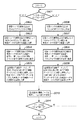
以下、本実施形態の記録システムで1ページ又は1つのジョブの記録を行う際の処理について、図5のフローチャートを参照して説明する。
【0036】
まず、ホスト装置200において、プリンタドライバは1パスモードと6パスモードのどちらが設定されているのかを判断する(ステップS501)。1パスモードが設定されていると判断すると、ホスト装置200のプリンタドライバは、記録ヘッドの使用吐出口としてn1からn16までの16ノズルを使用すると判断する(ステップS502)。
【0037】
次に、ステップS502で判断した記録ヘッドの使用吐出口に基づいて、ホスト装置200のプリンタドライバは、使用吐出口の情報として「n1からn16の16ノズル使用」を意味する制御データを記録装置100に送信する(ステップS503)。記録装置100はこの制御データを受信し、図4に示した第1ブロックから第4ブロックまでの16ノズルを使用するように設定する(ステップS504)。
【0038】
ホスト装置200のプリンタドライバは、1回の主走査に対応する画像データとして、記録ヘッドの使用吐出口数である16ノズル×記録媒体の記録幅のサイズの画像データを、記録装置100に送信する(ステップS505)。記録装置100は、送信された1主走査分の画像データを受信してプリントバッファに格納し、設定された記録ヘッドの使用吐出口を用いて1回の主走査での記録を行う(ステップS510)。
【0039】
ここで、記録装置100は、ステップS504で既に記録に使用するノズルを設定しており、画像データをプリントバッファに格納するのに必要な副走査方向のサイズがわかっており、書込みや読み出しの際のアドレッシングが効率的に行われる。
【0040】
ホスト装置200のプリンタドライバは、1ページ又は1つのジョブの全記録が終了したか否かの判断を行う(ステップS511)。終了していれば記録装置100に記録終了を意味する制御データを送信して記録を終了する。一方、記録が終了していなければ、記録媒体を16/600インチだけ搬送した後、ステップS501に戻り、1パスモードか6パスモードかの判断を再度行う。
【0041】
ステップS501の記録モードの判断において、6パスモードが設定されていると判断すると、ホスト装置200において、プリンタドライバは記録ヘッドの使用吐出口をn1からn12までの12ノズルを使用すると判断する(ステップS506)。
【0042】
そして、ステップS506で判断した記録ヘッドの使用吐出口に基づいて、ホスト装置200のプリンタドライバは、使用吐出口の情報として「n1からn12の12ノズル使用」を意味する制御データを記録装置100に送信する(ステップS507)。記録装置100はこの制御データを受信し、図4に示した第1ブロックから第3ブロックまでの12ノズルを使用するように設定する(ステップS508)。
【0043】
ホスト装置200のプリンタドライバは、1回の主走査に対応する画像データとして、記録ヘッドの使用吐出口数である12ノズル×記録媒体の記録幅のサイズの画像データを、記録装置100に送信する(ステップS509)。記録装置100は、送信された1主走査分の画像データを受信してプリントバッファに格納し、設定された記録ヘッドの使用吐出口を用いて1回の主走査での記録を行う(ステップS510)。
【0044】
ホスト装置200のプリンタドライバは、1ページ又は1つのジョブの全記録が終了したか否かの判断を行う(ステップS511)。終了していれば記録装置100に記録終了を意味する制御データを送信して記録を終了する。一方、記録が終了していなければ、記録媒体を2/600インチだけ搬送した後、ステップS501に戻り、1パスモードか6パスモードかの判断を再度行う。
【0045】
以上説明したように、本実施形態ではホスト装置において記録モードに応じて1回の主走査で使用する記録ヘッドの吐出口数を判断し、使用する吐出口数の情報と使用吐出口数に対応した1主走査分の画像データとを記録装置に送信する。記録装置は、どのような記録モードが設定されているのかを意識することなく、受信した使用吐出口数の情報に応じて記録に使用する吐出口を設定し、受信した画像データを記録するだけで、設定された記録モードに応じた画像が形成される。
【0046】
このため、記録装置側での記録モードや設定に応じた制御が簡略化され、ROMに格納すべきプログラム容量を大幅に削減できるので、記録装置に搭載するROMの容量を大幅に削減して記録装置のコストを低減することができる。
【0047】
また、記録ヘッドの使用吐出口の設定を1つの吐出口単位ではなく、4つの吐出口を単位として設定するようにしているため、ASICなどのロジック回路ののゲート数も大幅に削減することが可能となる。
【0048】
なお、本実施形態のような処理を行うことで、ホスト装置のプリンタドライバの負荷及びプリンタドライバ自体のプログラム容量は増大するが、ホスト装置として一般的に使用されるコンピュータは、近年処理速度の向上や記憶装置(半導体メモリ及びハードディスク)の容量の増大がめざましく、この程度の増大は問題とはならない。
【0049】
(第2の実施形態)
以下、本発明の第2の実施形態について説明する。第2の実施形態も上記第1の実施形態と同様な記録システムであり、以下の説明では上記第1の実施形態と同様な部分については説明を省略し、本実施形態の特徴的な部分を中心に説明する。
【0050】
第1の実施形態では、ホスト装置(プリンタドライバ)と記録装置との両方で記録ヘッドの使用吐出口に対する設定方法が同じであるが、第2の実施形態では、ホスト装置での使用吐出口に対する設定方法と、記録装置での使用吐出口に対する設定方法とが異なっている。
【0051】
第2の実施形態の記録装置は、記録ヘッドのノズル数が16であり、1パスモードと6パスモードとの2つの記録モードを有している点で第1の実施形態と同じであるが、1パスモードで使用するノズル番号がn2からn15の14ノズルであり、6パスモードで使用するノズル番号がn3からn14の12ノズルである点が第1の実施形態と異なっている。
【0052】
そして、ホスト装置200のプリンタドライバでは使用吐出口を吐出口単位で設定できるが、記録装置100では使用吐出口に対する設定はブロック単位でのみ可能である。
【0053】
以下、本実施形態の記録システムで1ページ又は1つのジョブの記録を行う際の処理について、図6のフローチャートを参照して説明する。
【0054】
まず、ホスト装置200において、プリンタドライバは1パスモードと6パスモードのどちらが設定されているのかを判断する(ステップS601)。1パスモードが設定されていると判断すると、ホスト装置200のプリンタドライバは、記録ヘッドの使用吐出口としてn2からn15までの14ノズルを使用すると判断する(ステップS602)。
【0055】
次に、ステップS602で判断した記録ヘッドの使用吐出口に基づいて、ホスト装置200のプリンタドライバは、使用吐出口の情報として「n2からn15の14ノズル使用」を意味する制御データを記録装置100に送信する(ステップS603)。記録装置100はこの制御データを受信し、開始ノズル番号n2が第1ブロックに属し、終了ノズル番号n15が第4ブロックに属することから、図4に示した第1ブロックから第4ブロックまでの16ノズルを使用するように設定する(ステップS604)。
【0056】
ここでは、ホスト装置200のプリンタドライバが送信する使用吐出口の情報に含まれる開始ノズル番号と終了ノズル番号とから、記録装置100が、開始ノズル番号n2が第1ブロックに属し、終了ノズル番号n15が第4ブロックに属することを解釈して第1ブロックから第4ブロックのノズルを使用するように設定するものとしたが、プリンタドライバが、記録装置100での設定がブロック単位であることが予めわかっていれば、記録装置に送信する制御データとして、第1ブロックから第4ブロックを使用することを意味するデータを送信してもよい。
【0057】
ホスト装置200のプリンタドライバは、1回の主走査に対応する画像データとして、記録ヘッドの使用吐出口数である14ノズルの画像データに、使用しない吐出口であるn1とn16の2つのノズルのためにヌルデータを付加した、16ノズル×記録媒体の記録幅のサイズの画像データを、記録装置100に送信する(ステップS605)。記録装置100は、送信された1主走査分の画像データを受信してプリントバッファに格納し、設定された記録ヘッドの使用吐出口である第1ブロックから第4ブロックを用いて1主走査分を記録する(ステップS610)。
【0058】
ここで、記録装置100は、ステップS604で既に記録に使用するノズルを設定しており、画像データをプリントバッファに格納するのに必要な副走査方向のサイズがわかっており、書込みや読み出しの際のアドレッシングが効率的に行われる。
【0059】
なお、記録装置100では16ノズルを用いて記録を行うが、ホスト装置のプリンタドライバから送信された画像データには、n1及びn16のノズルに対してはヌルデータが付加されているので、実際に記録されるのは14ノズル分である。
【0060】
ホスト装置200のプリンタドライバは、1ページ又は1つのジョブの全記録が終了したか否かの判断を行う(ステップS611)。終了していれば記録装置100に記録終了を意味する制御データを送信して記録を終了する。一方、記録が終了していなければ、記録媒体を14/600インチだけ搬送した後、ステップS601に戻り、1パスモードか6パスモードかの判断を再度行う。
【0061】
ステップS601の記録モードの判断において、6パスモードが設定されていると判断すると、ホスト装置200において、プリンタドライバは記録ヘッドの使用吐出口をn3からn14までの12ノズルを使用すると判断する(ステップS606)。
【0062】
そして、ステップS606で判断した記録ヘッドの使用吐出口に基づいて、ホスト装置200のプリンタドライバは、使用吐出口の情報として「n3からn14の12ノズル使用」を意味する制御データを記録装置100に送信する(ステップS607)。記録装置100はこの制御データを受信し、開始ノズル番号n3が第1ブロックに属し、終了ノズル番号n14が第4ブロックに属することから、図4に示した第1ブロックから第4ブロックまでの16ノズルを使用するように設定する(ステップS608)。
【0063】
ここでは、ホスト装置200のプリンタドライバが送信する使用吐出口の情報に含まれる開始ノズル番号と終了ノズル番号とから、記録装置100が、開始ノズル番号n3が第1ブロックに属し、終了ノズル番号n14が第4ブロックに属することを解釈して第1ブロックから第4ブロックのノズルを使用するように設定するものとしたが、プリンタドライバが、記録装置100での設定がブロック単位であることが予めわかっていれば、記録装置に送信する制御データとして、第1ブロックから第4ブロックを使用することを意味するデータを送信してもよい。
【0064】
ホスト装置200のプリンタドライバは、1回の主走査に対応する画像データとして、記録ヘッドの使用吐出口数である12ノズルの画像データに、使用しない吐出口である、n1、n2、n15、n16のためにヌルデータを付加した、16ノズル×記録媒体の記録幅のサイズの画像データを、記録装置100に送信する(ステップS609)。記録装置100は、送信された1主走査分の画像データを受信してプリントバッファに格納し、設定された記録ヘッドの使用吐出口である第1ブロックから第4ブロックを用いて1主走査分を記録する(ステップS610)。
【0065】
このとき、記録装置100では16ノズルを用いて記録を行うが、ホスト装置のプリンタドライバから送信された画像データには、n1、n2、n15及びn16のノズルに対してはヌルデータが付加されているので、実際に記録されるのは12ノズル分である。
【0066】
ホスト装置200のプリンタドライバは、1ページ又は1つのジョブの全記録が終了したか否かの判断を行う(ステップS611)。終了していれば記録装置100に記録終了を意味する制御データを送信して記録を終了する。一方、記録が終了していなければ、記録媒体を2/600インチだけ搬送した後、ステップS601に戻り、1パスモードか6パスモードかの判断を再度行う。
【0067】
以上説明したように、本実施形態ではホスト装置において記録モードに応じて1回の主走査で使用する記録ヘッドの吐出口数を判断し、使用する吐出口数の情報と、使用吐出口数に対応した1主走査分の画像データに、記録装置がブロックで使用吐出口を設定するために含まれる、実際には記録に使用しない吐出口に対応して付加したヌルデータとを記録装置に送信する。記録装置は、どのような記録モードが設定されているのかを意識することなく、受信した使用吐出口数の情報に応じて記録に使用する吐出口をブロックで設定し、受信した画像データを記録するだけで、設定された記録モードに応じた画像が形成される。
【0068】
このため、記録装置側での記録モードや設定に応じた制御が簡略化され、ROMに格納すべきプログラム容量を大幅に削減できるので、記録装置に搭載するROMの容量を大幅に削減して記録装置のコストを低減することができる。
【0069】
また、記録装置では記録ヘッドの使用吐出口の設定を1つの吐出口単位ではなく、4つの吐出口を単位として設定するようにしているため、ASICなどのロジック回路のゲート数も大幅に削減することが可能となる。
【0070】
なお、本実施形態でも、ホスト装置のプリンタドライバの負荷及びプリンタドライバ自体のプログラム容量は増大するが、ホスト装置として一般的に使用されるコンピュータは、近年処理速度の向上や記憶装置(半導体メモリ及びハードディスク)の容量の増大がめざましく、この程度の増大は問題とはならない。
【0071】
(第3の実施形態)
以下、本発明の第3の実施形態について説明する。第3の実施形態も上記第1及び第2の実施形態と同様な記録システムであり、以下の説明では上記の実施形態と同様な部分については説明を省略し、本実施形態の特徴的な部分を中心に説明する。
【0072】
第1及び第2の実施形態では、記録装置の記録ヘッドの吐出口列が1列であったが、第3の実施形態は、記録装置の記録ヘッドの吐出口列が複数列あるものである。
【0073】
図7は、第3の実施形態に係る記録ヘッドの吐出口の配列と使用吐出口の設定を示す図である。図7に示した記録ヘッド104は、ブラックインクを吐出する記録ヘッドであり、1/300インチのピッチ(1インチ当たり300個の密度)で、n=64個の吐出口(64ノズル)が配列された吐出口列を2列有しており、この2列は副走査方向に1/600インチだけオフセットされて配置されている。図中左側を第1吐出口列、右側を第2吐出口列と称する。記録ヘッドの駆動周波数は、15KHzであり、主走査方向に対して600dpiの密度で記録動作可能である。従って、記録動作時のキャリッジの主走査速度は25インチ/秒である。
【0074】
記録装置における使用吐出口の設定は、各吐出口列毎にブロック単位で設定可能であり、1ブロックは16ノズルで構成されている。n1からn16までの16ノズルは第1ブロック、n17からn32までの16ノズルは第2ブロック、n33からn48までの16ノズルは第3ブロック、n49からn64までの16ノズルは第4ブロックとして、各吐出口列毎に設定可能である。
【0075】
本実施形態の記録装置は、このような記録ヘッドを用い、各記録領域に対して第1吐出口列を使用した矢印Q1方向への主走査での記録(往路モード)と、第2吐出口列を使用した矢印Q2方向への主走査での記録(復路モード)とによる2パスの双方向記録が可能である。なお、本実施形態では、往路モード及び復路モードの両方で、実際に記録に使用する吐出口数は62であり、n1とn63の2つの吐出口は記録に使用しない。
【0076】
記録ヘッドの使用吐出口の設定に応じて、ホスト装置のプリンタドライバから1回の主走査で記録する画像データが送信される。記録装置は受信した画像データを記録モードに応じたプリントバッファに格納するが、プリントバッファに格納される画像データは、副走査方向の高さが使用吐出口数で、主走査方向の長さが記録媒体の記録幅である矩形のイメージとなる。
【0077】
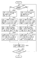
以下、本実施形態の記録システムで1ページ又は1つのジョブの記録を行う際の処理について、図8のフローチャートを参照して説明する。
【0078】
まず、ホスト装置200において、プリンタドライバは往路モードと復路モードのどちらが設定されているのかを判断する(ステップS801)。往路モードが設定されていると判断すると、ホスト装置200のプリンタドライバは、記録ヘッドの使用吐出口として、第1の吐出口列のn2からn63までの62ノズルを使用し、第2の吐出口列は使用しないと判断する(ステップS802)。
【0079】
次に、ステップS802で判断した記録ヘッドの使用吐出口に基づいて、ホスト装置200のプリンタドライバは、使用吐出口の情報として「第1の吐出口列は第1ブロックから4ブロック使用、第2の吐出口列は第1ブロックから0ブロック使用」を意味する制御データを記録装置に送信する(ステップS803)。記録装置はこの制御データを受信し、図7に示した第1の吐出口列は第1ブロックから第4ブロックまで使用し、第2の吐出口列は使用しないように設定する(ステップS804)。
【0080】
ホスト装置200のプリンタドライバは、1回の主走査に対応する画像データとして、記録ヘッドの使用吐出口数である62ノズル幅の画像データに、使用しない吐出口であるn1とn64の2つのノズルのためにヌルデータを付加した、64ノズル×記録媒体の記録幅のサイズの画像データを、記録装置100に送信する(ステップS805)。記録装置100は、送信された1主走査分の画像データを受信してプリントバッファに格納し、使用吐出口として設定された記録ヘッドの第1の吐出口列の第1ブロックから第4ブロックを用いて1主走査分を記録する(ステップS810)。
【0081】
ここで、記録装置100は、ステップS804で既に記録に使用するノズルを設定しており、画像データをプリントバッファに格納するのに必要な副走査方向のサイズがわかっており、書込みや読み出しの際のアドレッシングが効率的に行われる。
【0082】
なお、記録装置100では64ノズルを用いて記録を行うが、ホスト装置のプリンタドライバから送信された画像データには、n1及びn64のノズルに対してはヌルデータが付加されているので、実際に記録されるのは62ノズル分である。つまり、第1の吐出口列と第2の吐出口列を合わせた600dpiピッチで128ノズルの内、第1の吐出口列の62ノズルを使用した300dpiの画像データが記録される。
【0083】
ホスト装置200のプリンタドライバは、1ページ又は1つのジョブの全記録が終了したか否かの判断を行う(ステップS811)。終了していれば記録装置100に記録終了を意味する制御データを送信して記録を終了する。一方、記録が終了していなければ、ステップS801に戻り、往路モードか復路モードかの判断を再度行う。なお、ここでは往路での記録のみが行われたので、通常は記録は終了しておらず記録媒体の搬送は行われない。
【0084】
ステップS801の記録モードの判断において、復路モードが設定されていると判断すると、ホスト装置200において、プリンタドライバは記録ヘッドの使用吐出口として第2の吐出口列のn2からn63までの62ノズルを使用し、第1の吐出口列は使用しないと判断する(ステップS806)。
【0085】
そして、ステップS806で判断した記録ヘッドの使用吐出口に基づいて、ホスト装置200のプリンタドライバは、使用吐出口の情報として「第1の吐出口列は第1ブロックから0ブロック使用、第2の吐出口列は第1ブロックから4ブロック使用」を意味する制御データを記録装置に送信する(ステップS807)。記録装置100はこの制御データを受信し、図7に示した第2の吐出口列の第1ブロックから第4ブロックまでを使用し、第1の吐出口列は使用しないように設定する(ステップS808)。
【0086】
ホスト装置200のプリンタドライバは、1回の主走査に対応する画像データとして、記録ヘッドの使用吐出口数である62ノズル幅の画像データに、使用しない吐出口であるn1とn64の2つのノズルのためにヌルデータを付加した、64ノズル×記録媒体の記録幅のサイズの画像データを、記録装置100に送信する(ステップS809)。記録装置100は、送信された1主走査分の画像データを受信してプリントバッファに格納し、使用吐出口として設定された記録ヘッドの第2の吐出口列の第1ブロックから第4ブロックを用いて1主走査分を記録する(ステップS810)。
【0087】
このとき、記録装置100では64ノズルを用いて記録を行うが、ホスト装置のプリンタドライバから送信された画像データには、n1及びn64のノズルに対してはヌルデータが付加されているので、実際に記録されるのは62ノズル分である。つまり、第1の吐出口列と第2の吐出口列を合わせた600dpiピッチで128ノズルの内、第1の吐出口列の62ノズルを使用した300dpiの画像データが記録される。
【0088】
ホスト装置200のプリンタドライバは、1ページ又は1つのジョブの全記録が終了したか否かの判断を行う(ステップS811)。終了していれば記録装置100に記録終了を意味する制御データを送信して記録を終了する。一方、記録が終了していなければ、記録媒体を62/300インチだけ搬送した後、ステップS801に戻り、往路モードか復路モードかの判断を再度行う。
【0089】
以上説明したように、本実施形態ではホスト装置において記録方向に応じて1回の主走査毎に記録ヘッドの使用する吐出口列と使用する吐出口とを判断し、使用する吐出口列及び使用吐出口の情報と、記録装置側での使用吐出口の設定に合わせた1主走査分の画像データを記録装置に送信する。このとき、プリンタドライバは、記録装置側での使用吐出口の設定に、実際には記録で使用しない吐出口が含まれる場合には、画像データに、記録に使用しない吐出口に対応してヌルデータを付加する。記録装置は、記録方向を意識することなく、往路モードでも復路モードでも受信した使用吐出口の情報に応じて使用吐出口を設定し、受信した画像データを記録するだけで、設定された記録方向に応じた画像が形成される。
【0090】
このため、記録装置側での記録モードや設定に応じた制御が簡略化され、ROMに格納すべきプログラム容量を大幅に削減できるので、記録装置に搭載するROMの容量を大幅に削減して記録装置のコストを低減することができる。
【0091】
また、記録装置では記録ヘッドの使用吐出口の設定を1つの吐出口単位ではなく、16の吐出口を単位として設定するようにしているため、ASICなどのロジック回路のゲート数も大幅に削減することが可能となる。
【0092】
なお、本実施形態でも、ホスト装置のプリンタドライバの負荷及びプリンタドライバ自体のプログラム容量は増大するが、ホスト装置として一般的に使用されるコンピュータは、近年処理速度の向上や記憶装置(半導体メモリ及びハードディスク)の容量の増大がめざましく、この程度の増大は問題とはならない。
【0093】
なお、本実施形態では記録ヘッドの吐出口列を2列としたが、吐出口列の数はこれに限定されず、3列以上であってもよい。更に、本実施形態では吐出口列を横並びに配置したが、縦に並べて配置してもよい。
【0094】
[その他の実施形態]
また、記録装置での記録ヘッドの使用吐出口の設定は、第1及び第2の実施形態では4つの吐出口単位、第3の実施形態では16吐出口単位としたが、使用吐出口の設定単位はこれに限定されるものではなく、2以上の整数であればよく、更に2の累乗であれば、ASIC等のロジック回路のゲート数削減に対して一層効果がある。
【0095】
また、プリンタドライバが記録装置に対して送信する記録ヘッドの使用吐出口の情報は、第1及び第2の実施形態で用いた、開始ノズル番号、終了ノズル番号、及びノズル数からなる形式であっても、第3の実施形態で用いた、吐出口列毎に開始ブロック番号とブロック数からなる形式であってもよく、更には使用するノズルの範囲が特定される形式であればこれ以外の形式でもよい。例えば、吐出口列毎に設定が同じ場合は吐出口列の設定を省略してもよく、開始ノズル番号又は終了ノズル番号のいずれかとノズル数からなる形式でもよい。
【0096】
また上記の実施形態ではブラックインクを吐出する記録ヘッドのみを用いてモノクロ記録を行う記録装置を含む記録システムを例に挙げて説明したが、本発明は、シアン、マゼンタ、イエロー等のカラーインクをそれぞれ吐出する吐出口列又は記録ヘッドを複数備えた記録装置を含む記録システムにも適用できる。このような場合には、使用するインクの種類を区別するための情報を備えても良く、インク毎に吐出口列の数や吐出口数及び配置が異なっていても良い。
【0097】
また、上記の実施形態では、パス数や記録方向に応じて記録ヘッドの使用吐出口を異ならせる場合を例に挙げて説明したが、使用吐出口数は、記録媒体の種類、記録媒体のサイズ、記録解像度、1画素当りのデータ量等の他の記録パラメータに応じて変更してもよく、また1回の主走査ではなく、複数回の主走査、1ページ、1つのジョブを単位として記録ヘッドの使用吐出口を変更してもよい。
【0098】
また、以上の実施形態の説明は、インクジェット記録装置を例に挙げて説明したが、本発明は記録ヘッドを記録媒体上で走査させて記録を行うシリアル型の記録装置であれば、インクジェット以外の他の記録方式を用いた記録装置にも適用できる。
【0099】
以上の実施形態は、特にインクジェット記録方式の中でも、インク吐出を行わせるために利用されるエネルギーとして熱エネルギーを発生する手段(例えば電気熱変換体やレーザ光等)を備え、前記熱エネルギーによりインクの状態変化を生起させる方式を用いることにより記録の高密度化、高精細化が達成できる。
【0100】
その代表的な構成や原理については、例えば、米国特許第4723129号明細書、同第4740796号明細書に開示されている基本的な原理を用いて行うものが好ましい。この方式はいわゆるオンデマンド型、コンティニュアス型のいずれにも適用可能であるが、特に、オンデマンド型の場合には、液体(インク)が保持されているシートや液路に対応して配置されている電気熱変換体に、記録情報に対応していて核沸騰を越える急速な温度上昇を与える少なくとも1つの駆動信号を印加することによって、電気熱変換体に熱エネルギーを発生せしめ、記録ヘッドの熱作用面に膜沸騰を生じさせて、結果的にこの駆動信号に1対1で対応した液体(インク)内の気泡を形成できるので有効である。
【0101】
この気泡の成長、収縮により吐出用開口を介して液体(インク)を吐出させて、少なくとも1つの滴を形成する。この駆動信号をパルス形状とすると、即時適切に気泡の成長収縮が行われるので、特に応答性に優れた液体(インク)の吐出が達成でき、より好ましい。
【0102】
このパルス形状の駆動信号としては、米国特許第4463359号明細書、同第4345262号明細書に記載されているようなものが適している。なお、上記熱作用面の温度上昇率に関する発明の米国特許第4313124号明細書に記載されている条件を採用すると、さらに優れた記録を行うことができる。
【0103】
記録ヘッドの構成としては、上述の各明細書に開示されているような吐出口、液路、電気熱変換体の組み合わせ構成(直線状液流路または直角液流路)の他に熱作用面が屈曲する領域に配置されている構成を開示する米国特許第4558333号明細書、米国特許第4459600号明細書に記載された構成も本発明に含まれるものである。加えて、複数の電気熱変換体に対して、共通するスロットを電気熱変換体の吐出部とする構成を開示する特開昭59−123670号公報や熱エネルギーの圧力波を吸収する開口を吐出部に対応させる構成を開示する特開昭59−138461号公報に基づいた構成としても良い。
【0104】
加えて、上記の実施形態で説明した記録ヘッド自体に一体的にインクタンクが設けられたカートリッジタイプの記録ヘッドのみならず、装置本体に装着されることで、装置本体との電気的な接続や装置本体からのインクの供給が可能になる交換自在のチップタイプの記録ヘッドを用いてもよい。
【0105】
また、以上説明した記録装置の構成に、記録ヘッドに対する回復手段、予備的な手段等を付加することは記録動作を一層安定にできるので好ましいものである。これらを具体的に挙げれば、記録ヘッドに対してのキャッピング手段、クリーニング手段、加圧あるいは吸引手段、電気熱変換体あるいはこれとは別の加熱素子あるいはこれらの組み合わせによる予備加熱手段などがある。また、記録とは別の吐出を行う予備吐出モードを備えることも安定した記録を行うために有効である。
【0106】
さらに、記録装置の記録モードとしては黒色等の主流色のみの記録モードだけではなく、記録ヘッドを一体的に構成するか複数個の組み合わせによってでも良いが、異なる色の複色カラー、または混色によるフルカラーの少なくとも1つを備えた装置とすることもできる。
【0107】
以上説明した実施の形態においては、インクが液体であることを前提として説明しているが、室温やそれ以下で固化するインクであっても、室温で軟化もしくは液化するものを用いても良く、あるいはインクジェット方式ではインク自体を30°C以上70°C以下の範囲内で温度調整を行ってインクの粘性を安定吐出範囲にあるように温度制御するものが一般的であるから、使用記録信号付与時にインクが液状をなすものであればよい。
【0108】
加えて、積極的に熱エネルギーによる昇温をインクの固形状態から液体状態への状態変化のエネルギーとして使用せしめることで積極的に防止するため、またはインクの蒸発を防止するため、放置状態で固化し加熱によって液化するインクを用いても良い。いずれにしても熱エネルギーの記録信号に応じた付与によってインクが液化し、液状インクが吐出されるものや、記録媒体に到達する時点では既に固化し始めるもの等のような、熱エネルギーの付与によって初めて液化する性質のインクを使用する場合も本発明は適用可能である。
【0109】
このような場合インクは、特開昭54−56847号公報あるいは特開昭60−71260号公報に記載されるような、多孔質シート凹部または貫通孔に液状または固形物として保持された状態で、電気熱変換体に対して対向するような形態としてもよい。本発明においては、上述した各インクに対して最も有効なものは、上述した膜沸騰方式を実行するものである。
【0110】
なお、本発明は、複数の機器(例えばホストコンピュータ,インターフェース機器,リーダ,プリンタなど)から構成されるシステムに適用しても、一つの機器からなる装置(例えば、複写機,ファクシミリ装置など)に適用してもよい。また、本発明の目的は、前述した実施形態の機能を実現するソフトウェアのプログラムコードを記録した記憶媒体を、システムあるいは装置に供給し、そのシステムあるいは装置のコンピュータ(またはCPUやMPU)が記憶媒体に格納されたプログラムコードを読出し実行することによっても、達成されることは言うまでもない。
【0111】
この場合、記憶媒体から読出されたプログラムコード自体が前述した実施形態の機能を実現することになり、そのプログラムコードを記憶した記憶媒体は本発明を構成することになる。
【0112】
プログラムコードを供給するための記憶媒体としては、例えば、フロッピディスク,ハードディスク,光ディスク,光磁気ディスク,CD−ROM,CD−R,磁気テープ,不揮発性のメモリカード,ROMなどを用いることができる。
【0113】
また、コンピュータが読出したプログラムコードを実行することにより、前述した実施形態の機能が実現されるだけでなく、そのプログラムコードの指示に基づき、コンピュータ上で稼働しているOS(オペレーティングシステム)などが実際の処理の一部または全部を行い、その処理によって前述した実施形態の機能が実現される場合も含まれることは言うまでもない。
【0114】
さらに、記憶媒体から読出されたプログラムコードが、コンピュータに挿入された機能拡張ボードやコンピュータに接続された機能拡張ユニットに備わるメモリに書込まれた後、そのプログラムコードの指示に基づき、その機能拡張ボードや機能拡張ユニットに備わるCPUなどが実際の処理の一部または全部を行い、その処理によって前述した実施形態の機能が実現される場合も含まれることは言うまでもない。
【0115】
本発明を上記記憶媒体に適用する場合、その記憶媒体には、先に説明した(図5、図6及び図8に示す)フローチャートに対応するプログラムコードが格納されることになる。
【0116】
【発明の効果】
以上説明したように本発明によれば、記録装置は、どのような記録パラメータが設定されているのかを意識することなく、ホスト装置から受信した設定情報に応じて記録に使用する記録素子を設定し、走査を行う間に、ホスト装置から受信した画像データに従って記録素子を駆動して記録を行うだけで、設定された記録パラメータに応じた画像の記録が行われる。
【0117】
従って、記録装置側での記録パラメータの設定に関する制御が簡略化され、記録装置に搭載されるメモリ容量やロジック回路のゲート数を大幅に削減して記録装置のコストを低減し、サイズを小型にすることができる。
【図面の簡単な説明】
【図1】本発明の第1の実施形態に係るインクジェット記録装置の概略構成を示す斜視図である。
【図2】第1の実施形態の記録システムの主要な制御構成を示すブロック図である。
【図3】第1の実施形態の記録ヘッドのノズル配列を模式的に示す図である。
【図4】第1の実施形態における使用吐出口の設定を説明する図である。
【図5】第1の実施形態の記録システムで1ページ又は1つのジョブの記録を行う際の処理を示すフローチャートである。
【図6】第2の実施形態の記録システムで1ページ又は1つのジョブの記録を行う際の処理を示すフローチャートである。
【図7】第3の実施形態における使用吐出口の設定を説明する図である。
【図8】第3の実施形態の記録システムで1ページ又は1つのジョブの記録を行う際の処理を示すフローチャートである。
【符号の説明】
100 記録装置
101 キャリッジ
102 ガイド軸a
103 ガイド軸b
104 記録ヘッド
105 記録媒体
106 送りローラ
107 プラテン
108 スイッチ部と表示部
200 ホスト装置
201 受信バッファ −
202 CPU
203 ランダムアクセスメモリ部
204 機械コントロール部
205 機械部
206 センサ/SWコントロール部
207 センサ/SW部
208 表示素子コントロール部
209 表示素子部
210 記録ヘッドコントロール部[0001]
BACKGROUND OF THE INVENTION
The present invention relates to a recording system, a printer driver, and a recording method, and in particular, a recording head having recording element arrays arranged in a predetermined direction based on information transmitted from a host device in a direction crossing the arrangement direction. The present invention relates to a recording system including a recording apparatus that performs recording by scanning on a recording medium. More specifically, the present invention relates to a recording system and a recording method that enable high-speed and high-quality recording while reducing the cost of the recording apparatus by reducing the capacity of storage means (memory) provided in the recording apparatus.
[0002]
[Prior art]
Currently, various methods are known as recording methods used when recording information. However, the inkjet recording method is low noise, low device cost, low running cost, and small device. Therefore, it is widely used in recording devices and copying machines.
[0003]
2. Description of the Related Art Conventionally, a serial type ink jet recording apparatus is configured to perform one page recording by alternately repeating main scanning by a recording head and sub-scanning for transporting a recording medium. ) And an ejection energy generating element that selectively ejects ink from the nozzles are provided as recording elements.
[0004]
In recent years, in order to achieve color, high image quality, high resolution, and high-speed recording, the number of recording heads and the number of ejection ports of each recording head tend to increase.
[0005]
[Problems to be solved by the invention]
In general, such a recording apparatus is provided with a number of registers so that whether or not each discharge port is used for recording can be set in hardware. Along with this, a control logic such as an ASIC is provided. The number of gates in the circuit is also large.
[0006]
Some recording modes do not use all the ejection ports of the recording head, but the capacity of a memory (RAM) for storing image data is a capacity corresponding to an image to be recorded using all the ejection ports. Is required. When recording in such a recording mode, it is necessary to control only the ejection ports used for setting the mask and ASIC, etc. Therefore, if control is performed in software, the program capacity increases. This increases the capacity of the ROM.
[0007]
Furthermore, various recording modes and user settings are possible for multi-functionalization, but control according to these settings is mainly performed in the recording apparatus. The number of gates and ROM capacity tend to increase further.
[0008]
As described above, when the control becomes complicated as the recorded image becomes higher in image quality and multifunctional, the number of gates of the logic circuit and the capacity of the ROM increase, and the cost of the entire apparatus increases.
[0009]
The present invention has been made in view of the above situation, and enables high-quality recording while simplifying the control on the recording apparatus side and suppressing the size and cost of the apparatus.Recording systemThe purpose is to provide.
[0010]
[Means for Solving the Problems]
In order to achieve the above object, a recording system of the present invention uses a recording head having a recording element array in which a plurality of recording elements are arrayed along a predetermined direction, and a recording medium along a main scanning direction intersecting the array direction. Scan up and record, A recording mode for performing recording once for the recording area of the recording medium and a recording mode for performing recording for a plurality of times of scanning for the recording area of the recording medium can be executed.A recording device;
Connected to the recording device,For each scan of the recording head,A recording system including a host device that transmits control information and image data,
The host device is
Among the recording elements of the recording head,Compatible with recording modeSetting information for designating a recording element is transmitted as the control information;
Can be used in one scan recordingRecording elementThe amount of image data corresponding to the number ofTheBefore sending the control informationConfigured to send,
The recording device is
A setting means for setting usable recording elements in a plurality of units;
A print buffer for holding image data transmitted from the host device,
According to the setting information,Can be used in a single scanRecording element settingAnd access to the print buffer,
During the scanTo the aboveThe recording element set by the setting means,It is configured to perform recording by driving according to the image data.
[0013]
That is, according to the present invention, a recording head having recording element arrays arranged in a predetermined direction is scanned on a recording medium in a direction crossing the arrangement direction based on control information and image data transmitted from the host device. In response to a predetermined recording parameter, setting information specifying a recording element to be used for recording is transmitted as control information from the host device to the recording apparatus that performs recording in accordance with predetermined recording parameters. In accordance with the setting information, a recording element to be used is set, and in the host device, data to be recorded by the recording element used for recording corresponding to scanning is generated and transmitted as image data. During scanning, recording is performed by driving the recording element set by the setting means in accordance with the image data.
[0014]
In this way, the recording apparatus sets the recording element to be used for recording in accordance with the setting information received from the host apparatus without being aware of what recording parameters are set, and performs scanning. Further, only by driving the recording element in accordance with the image data received from the host device and performing recording, the image is recorded according to the set recording parameter.
[0015]
Therefore, the control related to the setting of the recording parameter on the recording apparatus side is simplified, the memory capacity mounted on the recording apparatus and the number of gates of the logic circuit are greatly reduced, the cost of the recording apparatus is reduced, and the size is reduced. can do.
[0016]
DETAILED DESCRIPTION OF THE INVENTION
Preferred embodiments of the present invention will be described below in detail with reference to the accompanying drawings.
[0017]
In this specification, “recording” (sometimes referred to as “printing”) is not only for forming significant information such as characters and graphics, but also for human beings, regardless of whether it is significant or not. Regardless of whether or not it has been manifested, it also represents a case where an image, a pattern, a pattern or the like is widely formed on a recording medium or the medium is processed.
[0018]
“Recording medium” refers not only to paper used in general recording apparatuses but also widely to cloth, plastic film, metal plate, glass, ceramics, wood, leather, and the like that can accept ink. Shall.
[0019]
Furthermore, “ink” (sometimes referred to as “liquid”) is to be interpreted broadly in the same way as the definition of “recording (printing)” above. It represents a liquid that can be used for forming a pattern or the like, processing a recording medium, or processing an ink (for example, solidification or insolubilization of a colorant in ink applied to the recording medium).
[0020]
(First embodiment)
FIG. 1 is a perspective view showing a schematic configuration of an ink jet recording apparatus according to a recording system as a first embodiment of the present invention.
[0021]
The
[0022]
In FIG. 1, a
[0023]
FIG. 2 is a block diagram showing the main control configuration of the recording system of the present embodiment. Character or image data to be recorded is transmitted from the
[0024]
Data stored in the
[0025]
The
[0026]
The sensor /
[0027]
The display
[0028]
In the recording system of the present embodiment, image data is generated by a printer driver installed for the
[0029]
FIG. 3 is a diagram illustrating the ejection port array of the
[0030]
The
[0031]
FIG. 4 is a diagram for explaining the setting of the use outlets of the recording head of the recording apparatus in the present embodiment. As shown in FIG. 4, in the present embodiment, the used ejection ports of the recording head can be set in units of blocks, and one block is composed of 4 nozzles. 4 nozzles from n1 to n4 can be set as 1st block, 4 nozzles from n5 to n8 can be set as 2nd block, 4 nozzles from n9 to n12 can be set as 3rd block, 4 nozzles from n13 to n16 can be set as 4th block It is.
[0032]
Image data to be recorded in one main scan is transmitted from the printer driver of the host device in accordance with the setting of the used discharge port of the recording head. The recording apparatus stores the received image data in an area secured as a print buffer in the
[0033]
The recording apparatus of this embodiment has a 1-pass mode and a 6-pass mode as recording modes. The 1-pass mode is a recording mode in which an image is recorded by one main scanning using 16 nozzles, and the recording medium is conveyed by 16/600 inches after each main scanning. The 6-pass mode is a recording mode in which 2 nozzles are used to record an image while complementing each recording area with 6 main scans, and the recording medium is conveyed by 2/600 inches after each main scan.
[0034]
The recording mode is set by the user via a user interface such as a setting screen of a printer driver for the
[0035]
Hereinafter, processing when recording one page or one job in the recording system of the present embodiment will be described with reference to the flowchart of FIG.
[0036]
First, in the
[0037]
Next, based on the use discharge port of the print head determined in step S502, the printer driver of the
[0038]
The printer driver of the
[0039]
Here, the
[0040]
The printer driver of the
[0041]
If it is determined in step S501 that the 6-pass mode is set, the
[0042]
Then, based on the used discharge port of the print head determined in step S506, the printer driver of the
[0043]
The printer driver of the
[0044]
The printer driver of the
[0045]
As described above, in the present embodiment, the number of ejection ports of the recording head used in one main scan is determined in the host device according to the recording mode, and information on the number of ejection ports to be used and one main ejection port corresponding to the number of ejection ports used. The image data for scanning is transmitted to the recording apparatus. The recording device sets the ejection port used for recording according to the received information on the number of used ejection ports, and records the received image data without being aware of what recording mode is set. An image corresponding to the set recording mode is formed.
[0046]
For this reason, the control according to the recording mode and setting on the recording device side is simplified and the program capacity to be stored in the ROM can be greatly reduced, so that the capacity of the ROM mounted on the recording device can be greatly reduced. The cost of the apparatus can be reduced.
[0047]
In addition, since the setting of the used ejection port of the recording head is set not in units of one ejection port but in units of four ejection ports, the number of gates of a logic circuit such as an ASIC can be greatly reduced. It becomes possible.
[0048]
Although the processing of the present embodiment increases the load of the printer driver of the host device and the program capacity of the printer driver itself, computers generally used as the host device have recently improved processing speed. In addition, the capacity of storage devices (semiconductor memories and hard disks) is remarkably increased, and this increase is not a problem.
[0049]
(Second Embodiment)
Hereinafter, a second embodiment of the present invention will be described. The second embodiment is also a recording system similar to the first embodiment. In the following description, the description of the same parts as the first embodiment is omitted, and the characteristic parts of the present embodiment are described. The explanation is centered.
[0050]
In the first embodiment, the setting method for the used discharge port of the print head is the same in both the host device (printer driver) and the printing apparatus, but in the second embodiment, the use discharge port in the host device is set. The setting method is different from the setting method for the used discharge port in the printing apparatus.
[0051]
The recording apparatus of the second embodiment is the same as the first embodiment in that the number of nozzles of the recording head is 16, and there are two recording modes of a 1-pass mode and a 6-pass mode. The difference from the first embodiment is that the nozzle numbers used in the 1-pass mode are 14 nozzles from n2 to n15, and the nozzle numbers used in the 6-pass mode are 12 nozzles from n3 to n14.
[0052]
In the printer driver of the
[0053]
Hereinafter, processing when recording one page or one job in the recording system of the present embodiment will be described with reference to a flowchart of FIG.
[0054]
First, in the
[0055]
Next, based on the used ejection port of the recording head determined in step S602, the printer driver of the
[0056]
Here, from the start nozzle number and the end nozzle number included in the information on the used discharge ports transmitted by the printer driver of the
[0057]
The printer driver of the
[0058]
Here, the
[0059]
Note that the
[0060]
The printer driver of the
[0061]
If it is determined in step S601 that the 6-pass mode is set, the
[0062]
Then, based on the used ejection port of the recording head determined in step S606, the printer driver of the
[0063]
Here, from the start nozzle number and the end nozzle number included in the information on the used discharge ports transmitted by the printer driver of the
[0064]
The printer driver of the
[0065]
At this time, the
[0066]
The printer driver of the
[0067]
As described above, in the present embodiment, the number of ejection ports of the recording head used in one main scan is determined in the host device according to the recording mode, and information on the number of ejection ports to be used and 1 corresponding to the number of ejection ports used. Null data added to the main scanning image data corresponding to the ejection ports that are not actually used for printing, which is included in the printing apparatus for setting the ejection ports to be used in blocks, is transmitted to the printing apparatus. The recording apparatus sets the ejection ports used for recording in blocks according to the received information on the number of used ejection ports, and records the received image data without being conscious of what recording mode is set. Only an image corresponding to the set recording mode is formed.
[0068]
For this reason, the control according to the recording mode and setting on the recording device side is simplified and the program capacity to be stored in the ROM can be greatly reduced, so that the capacity of the ROM mounted on the recording device can be greatly reduced. The cost of the apparatus can be reduced.
[0069]
In the recording apparatus, since the setting of the used ejection port of the recording head is set not in units of one ejection port but in units of four ejection ports, the number of gates of a logic circuit such as an ASIC is greatly reduced. It becomes possible.
[0070]
Even in this embodiment, the load of the printer driver of the host device and the program capacity of the printer driver itself are increased. However, computers generally used as the host device have recently been improved in processing speed and storage devices (semiconductor memory and The increase in the capacity of the hard disk) is remarkable, and this increase is not a problem.
[0071]
(Third embodiment)
Hereinafter, a third embodiment of the present invention will be described. The third embodiment is also a recording system similar to the first and second embodiments, and in the following description, the description of the same parts as the above embodiments is omitted, and the characteristic parts of the present embodiment The explanation will be focused on.
[0072]
In the first and second embodiments, the number of ejection port arrays of the recording head of the recording apparatus is one, but in the third embodiment, there are a plurality of ejection port arrays of the recording head of the recording apparatus. .
[0073]
FIG. 7 is a diagram illustrating the arrangement of the ejection ports and the setting of the ejection ports used in the recording head according to the third embodiment. The
[0074]
The setting of the used discharge ports in the printing apparatus can be set in units of blocks for each discharge port array, and one block is composed of 16 nozzles. 16 nozzles from n1 to n16 are the first block, 16 nozzles from n17 to n32 are the second block, 16 nozzles from n33 to n48 are the third block, 16 nozzles from n49 to n64 are the fourth block, It can be set for each discharge port array.
[0075]
The recording apparatus of the present embodiment uses such a recording head, performs recording in the main scanning in the direction of arrow Q1 using the first ejection port array for each recording region (forward path mode), and the second ejection ports. Two-pass bidirectional printing is possible by printing in the main scan in the direction of arrow Q2 (return path mode) using columns. In this embodiment, the number of ejection ports actually used for recording is 62 in both the forward path mode and the backward path mode, and the two ejection ports n1 and n63 are not used for recording.
[0076]
Image data to be recorded in one main scan is transmitted from the printer driver of the host device in accordance with the setting of the used ejection port of the recording head. The recording device stores the received image data in a print buffer corresponding to the recording mode. The image data stored in the print buffer is recorded with the height in the sub-scanning direction being the number of used ejection ports and the length in the main scanning direction being recorded. It becomes a rectangular image that is the recording width of the medium.
[0077]
Hereinafter, processing when recording one page or one job in the recording system of the present embodiment will be described with reference to a flowchart of FIG.
[0078]
First, in the
[0079]
Next, based on the used discharge port of the recording head determined in step S802, the printer driver of the
[0080]
The printer driver of the
[0081]
Here, the
[0082]
Note that the
[0083]
The printer driver of the
[0084]
If it is determined in step S801 that the return mode is set, the printer driver in the
[0085]
Then, based on the used discharge port of the recording head determined in step S806, the printer driver of the
[0086]
The printer driver of the
[0087]
At this time, the
[0088]
The printer driver of the
[0089]
As described above, in the present embodiment, the host device determines the ejection port array used by the recording head and the ejection port to be used for each main scan according to the recording direction, and uses the ejection port array and the usage. The image data for one main scan in accordance with the discharge port information and the setting of the used discharge port on the printing apparatus side is transmitted to the printing apparatus. At this time, if the setting of the used discharge port on the recording apparatus side includes a discharge port that is not actually used for recording, the printer driver sets null data corresponding to the discharge port not used for recording in the image data. Is added. The recording device sets the used ejection port according to the information about the used ejection port received in the forward mode and the return mode without being aware of the recording direction, and only records the received image data. An image corresponding to is formed.
[0090]
For this reason, the control according to the recording mode and setting on the recording device side is simplified and the program capacity to be stored in the ROM can be greatly reduced, so that the capacity of the ROM mounted on the recording device can be greatly reduced. The cost of the apparatus can be reduced.
[0091]
Further, in the recording apparatus, since the setting of the used ejection port of the recording head is set not in units of one ejection port but in units of 16 ejection ports, the number of gates of a logic circuit such as an ASIC is greatly reduced. It becomes possible.
[0092]
Even in this embodiment, the load of the printer driver of the host device and the program capacity of the printer driver itself are increased. However, computers generally used as the host device have recently been improved in processing speed and storage devices (semiconductor memory and The increase in the capacity of the hard disk) is remarkable, and this increase is not a problem.
[0093]
In this embodiment, the number of ejection port arrays of the recording head is 2. However, the number of ejection port arrays is not limited to this and may be 3 or more. Furthermore, in the present embodiment, the ejection port arrays are arranged side by side, but may be arranged side by side.
[0094]
[Other Embodiments]
Further, the setting of the discharge outlets of the recording head in the recording apparatus is set to four discharge openings in the first and second embodiments and 16 discharge openings in the third embodiment. The unit is not limited to this, and may be an integer of 2 or more, and if it is a power of 2, it is more effective for reducing the number of gates of a logic circuit such as an ASIC.
[0095]
In addition, the information on the discharge outlets of the print head that the printer driver sends to the printing apparatus is in the form of the start nozzle number, end nozzle number, and number of nozzles used in the first and second embodiments. However, it may be a format composed of the start block number and the number of blocks for each ejection port array used in the third embodiment, and further, other than this, as long as the range of nozzles to be used is specified. It may be in the form. For example, when the setting is the same for each discharge port array, the setting of the discharge port array may be omitted, and a format composed of either the start nozzle number or the end nozzle number and the number of nozzles may be used.
[0096]
In the above embodiment, a recording system including a recording apparatus that performs monochrome recording using only a recording head that discharges black ink has been described as an example. However, the present invention uses color inks such as cyan, magenta, and yellow. The present invention can also be applied to a recording system including a recording apparatus provided with a plurality of ejection port arrays or recording heads. In such a case, information for distinguishing the type of ink to be used may be provided, and the number of ejection port arrays, the number of ejection ports, and the arrangement may be different for each ink.
[0097]
Further, in the above-described embodiment, the case where the use discharge port of the print head is changed according to the number of passes and the print direction has been described as an example, but the use discharge port number is the type of the print medium, the size of the print medium, The recording head may be changed according to other recording parameters such as recording resolution, data amount per pixel, and the recording head in units of a plurality of main scans, one page, and one job instead of one main scan. The use outlet may be changed.
[0098]
In the above description of the embodiment, an inkjet recording apparatus has been described as an example. However, the present invention is not limited to an inkjet, as long as it is a serial type recording apparatus that performs recording by scanning a recording head on a recording medium. The present invention can also be applied to a recording apparatus using another recording method.
[0099]
The above embodiment includes means (for example, an electrothermal converter or a laser beam) that generates thermal energy as energy used to cause ink ejection, particularly in the ink jet recording system, and the ink is generated by the thermal energy. By using a system that causes a change in the state of recording, it is possible to achieve higher recording density and higher definition.
[0100]
As its typical configuration and principle, for example, those performed using the basic principle disclosed in US Pat. Nos. 4,723,129 and 4,740,796 are preferable. This method can be applied to both the so-called on-demand type and continuous type. In particular, in the case of the on-demand type, it is arranged corresponding to the sheet or liquid path holding the liquid (ink). By applying at least one drive signal corresponding to the recorded information and giving a rapid temperature rise exceeding nucleate boiling to the electrothermal transducer, the thermal energy is generated in the electrothermal transducer, and the recording head This is effective because film boiling occurs on the heat acting surface of the liquid, and as a result, bubbles in the liquid (ink) corresponding to the drive signal on a one-to-one basis can be formed.
[0101]
By the growth and contraction of the bubbles, liquid (ink) is ejected through the ejection opening to form at least one droplet. It is more preferable that the drive signal has a pulse shape, since the bubble growth and contraction is performed immediately and appropriately, and thus it is possible to achieve discharge of a liquid (ink) having particularly excellent responsiveness.
[0102]
As this pulse-shaped drive signal, those described in US Pat. Nos. 4,463,359 and 4,345,262 are suitable. Further excellent recording can be performed by employing the conditions described in US Pat. No. 4,313,124 of the invention relating to the temperature rise rate of the heat acting surface.
[0103]
As the configuration of the recording head, in addition to the combination configuration (straight liquid flow path or right-angle liquid flow path) of the discharge port, the liquid path, and the electrothermal transducer as disclosed in each of the above-mentioned specifications, the heat acting surface The configurations described in US Pat. No. 4,558,333 and US Pat. No. 4,459,600, which disclose a configuration in which is arranged in a bending region, are also included in the present invention. In addition, Japanese Patent Application Laid-Open No. 59-123670, which discloses a configuration in which a common slot is used as a discharge portion of an electrothermal transducer, or an opening that absorbs a pressure wave of thermal energy is discharged to a plurality of electrothermal transducers. A configuration based on Japanese Patent Laid-Open No. 59-138461 disclosing a configuration corresponding to each part may be adopted.
[0104]
In addition to the cartridge-type recording head in which the ink tank is integrally provided in the recording head itself described in the above embodiment, it can be electrically connected to the apparatus body by being attached to the apparatus body. A replaceable chip type recording head that can supply ink from the apparatus main body may be used.
[0105]
In addition, it is preferable to add recovery means, preliminary means, and the like for the recording head to the configuration of the recording apparatus described above because the recording operation can be further stabilized. Specific examples thereof include a capping unit for the recording head, a cleaning unit, a pressurizing or sucking unit, an electrothermal converter, a heating element different from this, or a preheating unit using a combination thereof. In addition, it is effective to provide a preliminary ejection mode for performing ejection different from recording in order to perform stable recording.
[0106]
Further, the recording mode of the recording apparatus is not limited to the recording mode of only the mainstream color such as black, but the recording head may be integrated or may be a combination of a plurality of colors. An apparatus having at least one of full colors can also be provided.
[0107]
In the embodiment described above, the description is made on the assumption that the ink is a liquid, but it may be an ink that is solidified at room temperature or lower, or an ink that is softened or liquefied at room temperature, Alternatively, the ink jet method generally controls the temperature of the ink so that the viscosity of the ink is within a stable discharge range by adjusting the temperature within a range of 30 ° C. or higher and 70 ° C. or lower. It is sufficient if the ink sometimes forms a liquid.
[0108]
In addition, it is solidified in a stand-by state in order to actively prevent temperature rise by heat energy as energy for changing the state of ink from the solid state to the liquid state, or to prevent ink evaporation. Ink that is liquefied by heating may be used. In any case, by applying heat energy according to the application of thermal energy according to the recording signal, the ink is liquefied and liquid ink is ejected, or when it reaches the recording medium, it already starts to solidify. The present invention can also be applied to the case where ink having a property of being liquefied for the first time is used.
[0109]
In such a case, the ink is held as a liquid or solid in a porous sheet recess or through-hole as described in JP-A-54-56847 or JP-A-60-71260, It is good also as a form which opposes with respect to an electrothermal converter. In the present invention, the most effective one for each of the above-described inks is to execute the above-described film boiling method.
[0110]
Note that the present invention can be applied to a system (for example, a copier, a facsimile machine, etc.) consisting of a single device even when applied to a system composed of a plurality of devices (for example, a host computer, interface device, reader, printer, etc.). You may apply. Another object of the present invention is to supply a storage medium storing software program codes for implementing the functions of the above-described embodiments to a system or apparatus, and the computer (or CPU or MPU) of the system or apparatus stores the storage medium. Needless to say, this can also be achieved by reading and executing the program code stored in the.
[0111]
In this case, the program code itself read from the storage medium realizes the functions of the above-described embodiments, and the storage medium storing the program code constitutes the present invention.
[0112]
As a storage medium for supplying the program code, for example, a floppy disk, a hard disk, an optical disk, a magneto-optical disk, a CD-ROM, a CD-R, a magnetic tape, a nonvolatile memory card, a ROM, or the like can be used.
[0113]
Further, by executing the program code read by the computer, not only the functions of the above-described embodiments are realized, but also an OS (operating system) operating on the computer based on the instruction of the program code. It goes without saying that a case where the function of the above-described embodiment is realized by performing part or all of the actual processing and the processing is included.
[0114]
Further, after the program code read from the storage medium is written into a memory provided in a function expansion board inserted into the computer or a function expansion unit connected to the computer, the function expansion is performed based on the instruction of the program code. It goes without saying that the CPU or the like provided in the board or the function expansion unit performs part or all of the actual processing, and the functions of the above-described embodiments are realized by the processing.
[0115]
When the present invention is applied to the storage medium, the storage medium stores program codes corresponding to the flowcharts described above (shown in FIGS. 5, 6, and 8).
[0116]
【The invention's effect】
As described above, according to the present invention, the recording device sets the recording element to be used for recording according to the setting information received from the host device without being aware of what recording parameters are set. During scanning, the image is recorded according to the set recording parameters simply by driving the recording element in accordance with the image data received from the host device.
[0117]
Therefore, the control related to the setting of the recording parameter on the recording apparatus side is simplified, the memory capacity mounted on the recording apparatus and the number of gates of the logic circuit are greatly reduced, the cost of the recording apparatus is reduced, and the size is reduced. can do.
[Brief description of the drawings]
FIG. 1 is a perspective view showing a schematic configuration of an ink jet recording apparatus according to a first embodiment of the present invention.
FIG. 2 is a block diagram illustrating a main control configuration of the recording system according to the first embodiment.
FIG. 3 is a diagram schematically illustrating a nozzle arrangement of the recording head according to the first embodiment.
FIG. 4 is a diagram for explaining setting of a use discharge port in the first embodiment.
FIG. 5 is a flowchart showing processing when recording one page or one job in the recording system of the first embodiment.
FIG. 6 is a flowchart showing processing when recording one page or one job in the recording system of the second embodiment.
FIG. 7 is a diagram for explaining setting of use discharge ports in a third embodiment.
FIG. 8 is a flowchart showing processing when recording one page or one job in the recording system of the third embodiment.
[Explanation of symbols]
100 recording device
101 Carriage
102 Guide shaft a
103 Guide shaft b
104 Recording head
105 Recording medium
106 Feed roller
107 platen
108 Switch and display
200 Host device
201 Receive buffer-
202 CPU
203 Random access memory
204 Machine control part
205 Machine part
206 Sensor / SW control unit
207 Sensor / SW unit
208 Display element control unit
209 Display element
210 Recording head controller
Claims (9)
該記録装置と接続され、前記記録ヘッドの走査毎に、制御情報と画像データとを送信するホスト装置と、を含む記録システムであって、
前記ホスト装置が、
前記記録ヘッドの記録素子のうち、記録モードに対応し、使用可能な記録素子を指定する設定情報を前記制御情報として送信し、
1回の走査の記録で使用可能な記録素子の数に対応した量の画像データを送信する前に、前記制御情報を送信するように構成され、
前記記録装置が、
使用可能な記録素子を複数単位で設定する設定手段と、
前記ホスト装置から送信された画像データを保持するプリントバッファとを備え、
前記設定情報に応じて、1回の走査で使用可能な記録素子の設定と前記プリントバッファへのアクセスを行い、
前記走査の間に前記設定手段によって設定された記録素子を、前記画像データに従って駆動して記録を行うように構成されている、ことを特徴とする記録システム。Using a recording head having a recording element row in which a plurality of recording elements arranged along a predetermined direction, performs printing by scanning over the recording medium along a main scanning direction crossing the arrangement direction, the recording of the recording medium A recording apparatus capable of executing a recording mode in which recording is performed once for an area and a recording mode in which recording is performed for a plurality of times with respect to a recording area of the recording medium ;
A printing system connected to the printing apparatus and including a host device that transmits control information and image data for each scan of the printing head ;
The host device is
Among the recording elements of the recording head , corresponding to the recording mode, setting information specifying a usable recording element is transmitted as the control information,
Before transmitting the amount of image data corresponding to the number of recording elements that can be used in one scanning recording, the control information is transmitted.
The recording device is
A setting means for setting usable recording elements in a plurality of units;
A print buffer for holding image data transmitted from the host device,
In accordance with the setting information, the print element that can be used in one scan is set and the print buffer is accessed.
Recording system, wherein said recording element set by the setting means is configured to perform recording by driving in accordance with the image data, that during the scan.
前記ホスト装置は、前記記録装置で設定された記録素子のうち、記録に使用しない記録素子に対応してヌルデータを付加して前記画像データを生成することを特徴とする請求項1に記載の記録システム。The recording apparatus sets a recording element that uses a plurality of recording elements as a unit,
2. The recording according to claim 1 , wherein the host device generates the image data by adding null data corresponding to recording elements not used for recording among recording elements set by the recording apparatus. system.
前記ホスト装置は、各記録ヘッドに対して前記設定情報及び前記画像データを送信することを特徴とする請求項1から6のいずれか1項に記載の記録システム。The recording apparatus has a plurality of recording heads so that color recording using a plurality of types of recording agents is possible,
Said host apparatus, a recording system according to any one of claims 1 6, characterized by transmitting a pre-Symbol setting information and the image data for each recording head.
Priority Applications (2)
| Application Number | Priority Date | Filing Date | Title |
|---|---|---|---|
| JP2002112660A JP3977128B2 (en) | 2002-04-15 | 2002-04-15 | Recording system |
| US10/411,298 US7315393B2 (en) | 2002-04-15 | 2003-04-11 | Printing system, printer driver, and printing method |
Applications Claiming Priority (1)
| Application Number | Priority Date | Filing Date | Title |
|---|---|---|---|
| JP2002112660A JP3977128B2 (en) | 2002-04-15 | 2002-04-15 | Recording system |
Publications (3)
| Publication Number | Publication Date |
|---|---|
| JP2003305855A JP2003305855A (en) | 2003-10-28 |
| JP2003305855A5 JP2003305855A5 (en) | 2005-07-28 |
| JP3977128B2 true JP3977128B2 (en) | 2007-09-19 |
Family
ID=28786685
Family Applications (1)
| Application Number | Title | Priority Date | Filing Date |
|---|---|---|---|
| JP2002112660A Expired - Fee Related JP3977128B2 (en) | 2002-04-15 | 2002-04-15 | Recording system |
Country Status (2)
| Country | Link |
|---|---|
| US (1) | US7315393B2 (en) |
| JP (1) | JP3977128B2 (en) |
Families Citing this family (9)
| Publication number | Priority date | Publication date | Assignee | Title |
|---|---|---|---|---|
| EP1355265B1 (en) * | 2002-04-15 | 2016-04-13 | Canon Kabushiki Kaisha | Colour data buffering for colour printing |
| JP4497807B2 (en) * | 2002-11-26 | 2010-07-07 | キヤノン株式会社 | Recording apparatus and method for controlling the apparatus |
| JP2005305832A (en) * | 2004-04-21 | 2005-11-04 | Seiko Epson Corp | Printer |
| JP4641459B2 (en) * | 2005-07-08 | 2011-03-02 | キヤノン株式会社 | Information processing apparatus and printer driver |
| JP2007130939A (en) * | 2005-11-11 | 2007-05-31 | Canon Finetech Inc | Printing control method and printing system |
| JP2010000699A (en) * | 2008-06-20 | 2010-01-07 | Canon Inc | Inkjet recording device |
| JP5409246B2 (en) | 2009-10-09 | 2014-02-05 | キヤノン株式会社 | Ink jet recording apparatus and recording head temperature control method |
| JP5875573B2 (en) | 2013-11-22 | 2016-03-02 | キヤノン株式会社 | Recording apparatus and bubble discharging method thereof |
| JP2022184353A (en) | 2021-06-01 | 2022-12-13 | キヤノン株式会社 | Recording device, control device, and program |
Family Cites Families (22)
| Publication number | Priority date | Publication date | Assignee | Title |
|---|---|---|---|---|
| CA1127227A (en) | 1977-10-03 | 1982-07-06 | Ichiro Endo | Liquid jet recording process and apparatus therefor |
| JPS5936879B2 (en) | 1977-10-14 | 1984-09-06 | キヤノン株式会社 | Thermal transfer recording medium |
| US4330787A (en) | 1978-10-31 | 1982-05-18 | Canon Kabushiki Kaisha | Liquid jet recording device |
| US4345262A (en) | 1979-02-19 | 1982-08-17 | Canon Kabushiki Kaisha | Ink jet recording method |
| US4463359A (en) | 1979-04-02 | 1984-07-31 | Canon Kabushiki Kaisha | Droplet generating method and apparatus thereof |
| US4313124A (en) | 1979-05-18 | 1982-01-26 | Canon Kabushiki Kaisha | Liquid jet recording process and liquid jet recording head |
| US4558333A (en) | 1981-07-09 | 1985-12-10 | Canon Kabushiki Kaisha | Liquid jet recording head |
| JPS58146929A (en) | 1982-02-25 | 1983-09-01 | Seiko Epson Corp | Method for receiving data of printer |
| JPS59123670A (en) | 1982-12-28 | 1984-07-17 | Canon Inc | Ink jet head |
| JPS59138461A (en) | 1983-01-28 | 1984-08-08 | Canon Inc | Liquid jet recording apparatus |
| JPS6071260A (en) | 1983-09-28 | 1985-04-23 | Erumu:Kk | Recorder |
| US5173717A (en) | 1990-02-02 | 1992-12-22 | Canon Kabushiki Kaisha | Ink jet recording head in which the ejection elements are driven in blocks |
| US5424605A (en) * | 1992-04-10 | 1995-06-13 | Silicon Video Corporation | Self supporting flat video display |
| JP3320268B2 (en) | 1994-09-02 | 2002-09-03 | キヤノン株式会社 | Recording head, recording apparatus and recording method using the recording head |
| JPH08132647A (en) | 1994-11-07 | 1996-05-28 | Fuji Xerox Co Ltd | Image recording apparatus |
| JP3576694B2 (en) | 1996-04-23 | 2004-10-13 | キヤノン株式会社 | Ink jet recording method, apparatus thereof, image processing method, and printing method for executing image processing method |
| JPH09286125A (en) | 1996-04-23 | 1997-11-04 | Canon Inc | Method for ink jet recording and apparatus therefor |
| US5971518A (en) | 1997-01-28 | 1999-10-26 | Lexmark International, Inc. | Method of printing with an ink jet printer to inhibit the formation of a print artifact |
| US6097499A (en) | 1997-11-14 | 2000-08-01 | Lexmark International, Inc. | Methods and apparatus for isochronous printing with minimal buffering |
| US6128098A (en) | 1997-11-17 | 2000-10-03 | Canon Kabushiki Kaisha | Control over print head driving parameters |
| DE59913902D1 (en) * | 1998-03-21 | 2006-11-23 | Ebm Papst St Georgen Gmbh & Co | Electronically commutated motor |
| EP1681165A3 (en) * | 1999-03-10 | 2009-04-01 | Seiko Epson Corporation | Dot formation position misalignment adjustment performed using pixel-level information indicating dot non-formation |
-
2002
- 2002-04-15 JP JP2002112660A patent/JP3977128B2/en not_active Expired - Fee Related
-
2003
- 2003-04-11 US US10/411,298 patent/US7315393B2/en not_active Expired - Fee Related
Also Published As
| Publication number | Publication date |
|---|---|
| JP2003305855A (en) | 2003-10-28 |
| US7315393B2 (en) | 2008-01-01 |
| US20030193674A1 (en) | 2003-10-16 |
Similar Documents
| Publication | Publication Date | Title |
|---|---|---|
| JPH11207948A (en) | Recording device and recording control method | |
| JP3884993B2 (en) | Image recording apparatus and image recording method | |
| JP3667118B2 (en) | Recording apparatus and recording method | |
| JP3977128B2 (en) | Recording system | |
| US6655772B2 (en) | Printing apparatus and printhead temperature management method | |
| JP4666810B2 (en) | Image recording apparatus and control method thereof | |
| JP2003305836A (en) | Recorder, information processor, method of controlling the same, and program | |
| JP3937808B2 (en) | Inkjet recording device | |
| JP2003305837A (en) | Recorder, information processor, method of controlling the same, and program | |
| JP4018433B2 (en) | Recording device | |
| JP3720773B2 (en) | Inkjet recording apparatus and inkjet recording method | |
| US6652065B2 (en) | Printing apparatus and control method therefor | |
| JP4401618B2 (en) | Recording apparatus and buffer management method | |
| JP3278315B2 (en) | Dot data shift method, recording method, and recording apparatus using the recording method | |
| JP4785306B2 (en) | Ink jet recording apparatus and ink temperature control method in the apparatus | |
| JP4144852B2 (en) | Inkjet recording apparatus and inkjet recording method | |
| JP4532684B2 (en) | Inkjet recording device | |
| JP2000025208A (en) | Recorder, control method thereof and computer readable memory | |
| JP2005059304A (en) | Inkjet recording apparatus and control method therefor | |
| JP2003305902A (en) | Recorder, information processor, their controlling method, and program | |
| JP2005022383A (en) | Inkjet printer and method | |
| JP3667071B2 (en) | Ink jet recording apparatus and recording processing liquid print data generation method | |
| JP2001187446A (en) | Recording device and method | |
| JP4018434B2 (en) | Recording apparatus and recording control method | |
| JP4262246B2 (en) | Image recording apparatus and control method thereof |
Legal Events
| Date | Code | Title | Description |
|---|---|---|---|
| A521 | Request for written amendment filed |
Free format text: JAPANESE INTERMEDIATE CODE: A523 Effective date: 20041215 |
|
| A621 | Written request for application examination |
Free format text: JAPANESE INTERMEDIATE CODE: A621 Effective date: 20041215 |
|
| A977 | Report on retrieval |
Free format text: JAPANESE INTERMEDIATE CODE: A971007 Effective date: 20070201 |
|
| A131 | Notification of reasons for refusal |
Free format text: JAPANESE INTERMEDIATE CODE: A131 Effective date: 20070209 |
|
| A521 | Request for written amendment filed |
Free format text: JAPANESE INTERMEDIATE CODE: A523 Effective date: 20070410 |
|
| TRDD | Decision of grant or rejection written | ||
| A01 | Written decision to grant a patent or to grant a registration (utility model) |
Free format text: JAPANESE INTERMEDIATE CODE: A01 Effective date: 20070601 |
|
| A61 | First payment of annual fees (during grant procedure) |
Free format text: JAPANESE INTERMEDIATE CODE: A61 Effective date: 20070620 |
|
| FPAY | Renewal fee payment (event date is renewal date of database) |
Free format text: PAYMENT UNTIL: 20100629 Year of fee payment: 3 |
|
| R150 | Certificate of patent or registration of utility model |
Free format text: JAPANESE INTERMEDIATE CODE: R150 |
|
| FPAY | Renewal fee payment (event date is renewal date of database) |
Free format text: PAYMENT UNTIL: 20110629 Year of fee payment: 4 |
|
| FPAY | Renewal fee payment (event date is renewal date of database) |
Free format text: PAYMENT UNTIL: 20120629 Year of fee payment: 5 |
|
| FPAY | Renewal fee payment (event date is renewal date of database) |
Free format text: PAYMENT UNTIL: 20120629 Year of fee payment: 5 |
|
| FPAY | Renewal fee payment (event date is renewal date of database) |
Free format text: PAYMENT UNTIL: 20130629 Year of fee payment: 6 |
|
| LAPS | Cancellation because of no payment of annual fees |