JP3975868B2 - Control device for internal combustion engine - Google Patents
Control device for internal combustion engine Download PDFInfo
- Publication number
- JP3975868B2 JP3975868B2 JP2002262535A JP2002262535A JP3975868B2 JP 3975868 B2 JP3975868 B2 JP 3975868B2 JP 2002262535 A JP2002262535 A JP 2002262535A JP 2002262535 A JP2002262535 A JP 2002262535A JP 3975868 B2 JP3975868 B2 JP 3975868B2
- Authority
- JP
- Japan
- Prior art keywords
- cam
- switching
- ignition timing
- output
- internal combustion
- Prior art date
- Legal status (The legal status is an assumption and is not a legal conclusion. Google has not performed a legal analysis and makes no representation as to the accuracy of the status listed.)
- Expired - Fee Related
Links
Images


Classifications
-
- Y—GENERAL TAGGING OF NEW TECHNOLOGICAL DEVELOPMENTS; GENERAL TAGGING OF CROSS-SECTIONAL TECHNOLOGIES SPANNING OVER SEVERAL SECTIONS OF THE IPC; TECHNICAL SUBJECTS COVERED BY FORMER USPC CROSS-REFERENCE ART COLLECTIONS [XRACs] AND DIGESTS
- Y02—TECHNOLOGIES OR APPLICATIONS FOR MITIGATION OR ADAPTATION AGAINST CLIMATE CHANGE
- Y02T—CLIMATE CHANGE MITIGATION TECHNOLOGIES RELATED TO TRANSPORTATION
- Y02T10/00—Road transport of goods or passengers
- Y02T10/10—Internal combustion engine [ICE] based vehicles
- Y02T10/12—Improving ICE efficiencies
-
- Y—GENERAL TAGGING OF NEW TECHNOLOGICAL DEVELOPMENTS; GENERAL TAGGING OF CROSS-SECTIONAL TECHNOLOGIES SPANNING OVER SEVERAL SECTIONS OF THE IPC; TECHNICAL SUBJECTS COVERED BY FORMER USPC CROSS-REFERENCE ART COLLECTIONS [XRACs] AND DIGESTS
- Y02—TECHNOLOGIES OR APPLICATIONS FOR MITIGATION OR ADAPTATION AGAINST CLIMATE CHANGE
- Y02T—CLIMATE CHANGE MITIGATION TECHNOLOGIES RELATED TO TRANSPORTATION
- Y02T10/00—Road transport of goods or passengers
- Y02T10/10—Internal combustion engine [ICE] based vehicles
- Y02T10/40—Engine management systems
Description
【0001】
【発明の属する技術分野】
この発明は、いわゆるカム切換型の可変動弁機構、特に、各々のカムの特性が、それぞれ異なる吸入負圧を前提として設定されている可変動弁機構を備えた内燃機関の制御装置に関する。
【0002】
【従来の技術】
内燃機関の吸気弁側の可変動弁機構として、バルブリフト特性が異なる少なくとも2つのカムを有し、これらのカムを選択して吸気弁を駆動するようにした、いわゆるカム切換型の可変動弁機構が従来から知られている。しかし、実用されている内燃機関の多くは、機関低速域に適した低速用カムと機関高速域に適した高速用カムとを用いたもので、これらのカムによるトルク特性(トルクカーブ)が、同じ吸入負圧の下で、ある回転数で互いに交差する特性を有している。従って、この交差する回転数でカムの切換を行うことにより、基本的に切換に伴うトルク変化は小さいものとなる。
【0003】
これに対し、それぞれ異なる吸入負圧の下で用いることを前提として、低負荷域に適した作動角の小さな燃費重視カムと高負荷域に適した作動角の大きな出力重視カムとに切り換えるようにしたものがある。これは、コントロールユニットからの制御信号によって開度が制御可能ないわゆる電子制御スロットル弁と組み合わせて用いるものであり、燃費重視カムで運転するときには、出力重視カム選択時に比べて、相対的に吸入負圧が低くなる(大気圧に近付く)ようにスロットル弁開度が制御され、その結果、低負荷時のポンピングロスが大幅に低減する。この場合、同じ吸入負圧の下でのそれぞれのカムによるトルクカーブは、互いに交差することがない。つまり、それぞれのカムのカムプロフィールが大きく異なっている。
【0004】
従って、両者の切換の境界においては、同じトルクおよび機関回転速度であっても、使用されているカムによって要求点火時期が異なるものとなる。
【0005】
そのため、一方のカムから他方のカムへ切り換える際には、同時に点火時期を切り換える必要があるが、この点火時期の切換のタイミングが、実際のカム切換と一致していないと、ノッキングが発生したり、ヘジテーションが発生するなど運転性に影響を与える。
【0006】
このような点火時期切換タイミングの問題に対し、特開平7−224746号公報においては、カム切換指令が出力されてから吸入空気量が変化するまでの時間をカム切換の作動遅れ時間として作動油温毎に学習しておき、カム切換時には、カム切換指令の出力後、この作動遅れ時間が経過したタイミングで点火時期を切り換えるようにした技術が開示されている。
【0007】
【発明が解決しようとする課題】
上記従来の技術では、吸入空気量が変化した時点を実際のカム切換時点とみなしているが、吸気系の容積による空気量変化の応答遅れなどもあって、学習したカム切換の作動遅れ時間の精度が必ずしも十分なものとはならない。そのため、この作動遅れ時間経過時点と実際のカム切換時点とが多少ずれることがあり、その場合には、ノッキングやヘジテーションといった運転性の悪化が生じてしまう。
【0008】
特に、カム切換機構がロッカアームの形態で各気筒毎に設けられている構成では、それぞれのカム切換機構での実際のカム切換タイミングがある程度異なるものとなるが、上記の技術では、このように気筒毎に異なる切換タイミングに対処することができない。
【0009】
【課題を解決するための手段】
この発明に係る内燃機関の制御装置は、バルブリフト特性が異なる少なくとも2つのカムを有し、これらのカムを選択して吸気弁を駆動するカム切換機構が各気筒毎に設けられた可変動弁機構を備えている。また、アクセル操作部材、例えばアクセルペダルの操作量を検出するセンサと、制御信号により開度が制御可能なスロットル弁と、点火時期を制御する点火時期制御手段と、を備えており、上記カムの切換の際に、それぞれのカムにより異なる吸入負圧とすべく上記スロットル弁の開度を制御するとともに、それぞれのカムにより異なる要求点火時期に点火時期を制御するようになっている。
【0010】
そして、本発明では、上記可変動弁機構にカム切換指令が出力されてから所定の期間、切換前のカムでの点火時期許容限界および切換後のカムでの点火時期許容限界を越えない中間的な点火時期に補正する。
【0011】
具体的には、一方のカムでの要求点火時期と他方のカムでの要求点火時期との中間の点火時期に一時的に制御する。
【0012】
上記の所定の期間とは、全てのカム切換機構でカム切換が完了すると考えられる期間、特に、その切換のばらつきを考慮した期間である。なお、この期間は、固定的な時間として与えてもよく、あるいは、油温等に応じて設定することもできる。つまり、この期間内では、複数のカム切換機構が、実際にはどちらのカムを選択しているか不明である。そのため本発明では、この期間の間、どちらのカムでも運転性に大きな影響がない妥協点となる中間的な値に点火時期を制御するのである。そして、この期間の経過後、切換後のカムでの要求点火時期に制御する。
【0013】
【発明の効果】
この発明に係る内燃機関の制御装置によれば、複数のカム切換機構の実際のカム切換タイミングがばらついても、ノッキングやヘジテーションといった運転性の悪化を十分に抑制することができ、かつ高精度なカム切換タイミングの検出手段が不要となる。
【0014】
【発明の実施の形態】
以下、この発明の好ましい実施の形態を図面に基づいて詳細に説明する。
【0015】
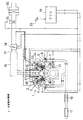
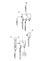
図1は、この発明をV型6気筒のガソリン機関1に適用した実施例を示しており、左右バンクの吸気弁3側に、後述するカム切換型の可変動弁機構2がそれぞれ設けられている。排気弁4側の動弁機構は、排気カムシャフト5により排気弁4を駆動する直動型のものであり、そのバルブリフト特性は、常に一定である。
【0016】
左右バンクの排気マニホルド6は、触媒コンバータ7に接続され、かつこの触媒コンバータ7の上流位置に、排気空燃比を検出する空燃比センサ8が設けられている。左右バンクの排気通路9は、触媒コンバータ7の下流側で合流し、さらに下流に、第2の触媒コンバータ10および消音器11を備えている。
【0017】
各気筒の吸気ポートにはブランチ通路15が接続され、かつこの6本のブランチ通路15の上流端が、コレクタ16にそれぞれ接続されている。上記コレクタ16の一端には、吸気入口通路17が接続されており、この吸気入口通路17に、電子制御スロットル弁18が設けられている。この電子制御スロットル弁18は、電気モータからなるアクチュエータを備え、エンジンコントロールユニット19から与えられる制御信号によって、その開度が制御される。なお、スロットル弁18の実際の開度を検出する図示せぬセンサを一体に備えており、その検出信号に基づいて、スロットル弁開度が目標開度にクローズドループ制御される。また、スロットル弁18の上流に、吸入空気流量を検出するエアフロメータ25が配置され、さらに上流にエアクリーナ20が設けられている。
【0018】
また、機関回転速度およびクランク角位置を検出するために、クランクシャフトに対してクランク角センサ21が設けられており、さらに、運転者により操作されるアクセルペダル開度(踏込量)を検出するアクセル開度センサ22を備えている。これらの検出信号は、上記のエアフロメータ25や空燃比センサ8の検出信号とともに、エンジンコントロールユニット19に入力されている。エンジンコントロールユニット19では、これらの検出信号に基づいて、燃料噴射弁23の噴射量や噴射時期、点火プラグ24による点火時期、可変動弁機構2によるバルブリフト特性、スロットル弁18の開度、などを制御する。
【0019】
上記の吸気弁3側の可変動弁機構2は、この実施例では、吸気弁3のリフト・作動角を大小2段階に切り換えるカム切換型のリフト・作動角可変機構と、そのリフトの中心角の位相(図示せぬクランクシャフトに対する位相)を連続的に進角もしくは遅角させる位相可変機構と、が組み合わされて構成されている。
【0020】
上記リフト・作動角可変機構は、例えば前述した特開平7−224746号公報や特許第2722815号公報等に記載されているように、吸気カムシャフト27に、リフトおよび作動角の大きな出力重視カム(Highカム)とリフトおよび作動角の小さな燃費重視カム(Lowカム)とが設けられ、かつカム切換機構として、上記燃費重視カムに従動する主ロッカアームおよび上記出力重視カムに従動する副ロッカアームと、両者を係合離脱する油圧式係合機構と、を各気筒毎に備えたものである。吸気弁3は主ロッカアームによって押圧されるようになっており、上記係合機構を介して主ロッカアームと副ロッカアームとが一体に揺動する構成となっている。つまり、両者を係合した状態では、出力重視カムによって大作動角・大リフトの特性となり、両者を離脱した状態では、副ロッカアームは自由に揺動することから、燃費重視カムによって小作動角・小リフトの特性となる。
【0021】
また、上記位相可変機構は、いわゆるVTCと呼ばれる機構であり、特開2001−280167号公報や特開2002−89303号公報等に記載されているように、吸気カムシャフト27の前端部に、クランクシャフトにタイミングチェーンもしくはタイミングベルトを介して連動するスプロケットが設けられ、このスプロケットと吸気カムシャフト27とを、所定の角度範囲内において位相制御用アクチュエータが相対回転させる構成となっている。上記位相制御用アクチュエータは、例えば油圧式、電磁式などの回転型アクチュエータからなり、エンジンコントロールユニット19からの制御信号によって制御される。この位相可変機構では、リフト特性の曲線自体は変わらずに、全体が進角もしくは遅角する。そして、この変化は、連続的に得ることができる。この位相可変機構の制御状態は、吸気カムシャフト27の回転位置に応答するカム角度センサ26によって検出される。
【0022】
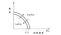
図2は、上記リフト・作動角可変機構によるカムの切換の特性を示しており、図示するように、低速低負荷側の領域で、小リフト・小作動角の燃費重視カムとなり、高負荷域および高速域で、大リフト・大作動角の出力重視カムとなる。なお、それぞれの切換には適宜なヒステリシスが与えられており、出力重視カムから燃費重視カムへの切換は図の境界線aで、燃費重視カムから出力重視カムへの切換は境界線bで、それぞれ行われる。このカムの切換に伴って、吸入負圧つまりスロットル弁開度が切り換えられるとともに、点火時期が切り換えられるのであるが、本実施例では、吸気系容積による吸入負圧変化の応答遅れを考慮して、トルク段差が生じないような制御を行っている。
【0023】
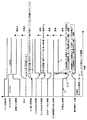
図3は、出力重視カムから燃費重視カムへの切換の際の作用を示すタイミングチャートである。これは、例えば要求トルクの低下により上記の境界線aを横切ったときの切換に相当するが、理解を容易にするために、このタイミングチャートでは切換の前後で要求トルクが変化しないものとして示している。
【0024】
上記の境界線aを横切ったときに、スロットル切換タイミング信号が出力され、カムに対応したスロットル弁開度の変更が実行される。具体的には、切換後の燃費重視カムで等トルクとなる吸入負圧を目標吸入負圧として、この目標吸入負圧に必要な目標スロットル弁開度が決定される。電子制御スロットル弁18の実際の開度は、この目標スロットル弁開度に沿って増加する。ここで、実際のカムの切換前は、出力重視カムで運転されているので、この時点では、上記の目標吸入負圧に対し必要な目標スロットル弁開度は、出力重視カムを基準として設定される。つまり、同じ圧力差であれば出力重視カムの方が燃費重視カムよりもシリンダに流入する空気量が大となるので、同じ目標吸入負圧に維持するには、燃費重視カムでの運転時よりも出力重視カムでの運転時の方が、より大きなスロットル弁開度が必要となる。
【0025】
このスロットル弁開度の増加によって、コレクタ16内の吸入負圧(Boost)は、図示するように徐々に低下する。つまり、徐々に大気圧に近付く。本実施例では、このとき、まだ実際のカム切換は行われておらず、出力重視カム(Highカム)によって運転されている。従って、そのままでは吸入負圧の低下に伴ってトルクが上昇してしまうので、トルクダウン点火時期として示すように、上記のスロットル切換タイミング信号に基づいて、点火時期のリタードを開始し、トルク増加を相殺する。この点火時期リタードのリタード量は、適宜な時定数の一次遅れに沿うように徐々に増加する。これにより、コレクタ16内の実際の吸入負圧の変化に対応したものとなり、最終的に発生するトルクを等トルクに抑制できる。
【0026】
上記のスロットル切換タイミング信号の出力から所定の切換時Boost合わせ期間が経過したら、カム切換信号(VVLソレノイド信号)が出力され、上述したリフト・作動角可変機構のカムの切換が実行される。上記の切換時Boost合わせ期間は、コレクタ16内の実際の吸入負圧が目標吸入負圧に達するまでの遅れ時間に相当するものであり、機関回転速度と、両カムで等トルクとなる吸入負圧の差とに基づいて設定される。上記のカム切換信号によって、各気筒のカム切換機構へ供給される油圧を制御するソレノイド弁(図示せず)が切り換えられ、油圧の応答遅れ等による多少の遅れ期間の後に、実際のカム切換が行われる。従って、実際の吸入負圧が目標吸入負圧に達した状態で、出力重視カムから燃費重視カムへ切り換えられることになり、カム切換によるトルク段差を生じることがない。
【0027】
なお、目標スロットル弁開度は、カム切換に伴って、図示のようにBoost合わせ期間中よりも小さくなる。つまり、前述したように、燃費重視カムで切換前と等トルクとなる吸入負圧を目標吸入負圧として、この目標吸入負圧に必要な目標スロットル弁開度が決定されるのであるが、ここでは、既に燃費重視カムにより運転されているので、出力重視カムで運転されているBoost合わせ期間中に比べて、必要な目標スロットル弁開度が小さくなるのである。
【0028】
ここで、カム切換信号の出力から実際にカム切換が完了するまでの遅れは、種々の要因によって変化し、また各気筒のカム切換機構毎に多少異なるものとなるが、これらの全てを見込んで、所定の期間つまりVVL切換ばらつき期間が設定されている。従って、複数のカム切換機構は、この期間内のどこかでカム切換が完了するのであるが、実際のカム切換タイミングは、厳密には特定されない。そのため、このVVL切換ばらつき期間内では、双方のカムで運転性に影響の出ない中間的な値に、点火時期および燃料噴射量の補正を行っている。
【0029】
図中にLowCam点火時期として示すのは、燃費重視カムでの要求点火時期であり、HighCam点火時期として示すのは、出力重視カムでの要求点火時期である。Boost合わせ期間中は、シリンダ内吸入空気量が増加するので、これに応じて点火時期は遅角する。なお、切換前後で等トルクであっても、燃費重視カムでは、フリクションやポンプ損失の低減によりシリンダ内吸入空気量が少なくなる。
【0030】
切換期間中点火時期として示すのは、前述したVVL切換ばらつき期間中の点火時期であり、切換前の出力重視カムでの点火時期許容限界および切換後の燃費重視カムでの点火時期許容限界をいずれも越えない中間的な点火時期に設定される。例えば、出力重視カムでの要求点火時期と燃費重視カムでの要求点火時期との中間の点火時期、あるいは、カム切換開始直前の点火時期と切換後の燃費重視カムでの要求点火時期との中間の点火時期、とすることができる。あるいは、後述するように、出力重視カムでの要求点火時期をベースとして、これに運転条件に応じた補正を加えて求めることもできる。
【0031】
従って、最終的な目標点火時期としては、スロットル切換タイミング信号の出力までは、出力重視カムでの要求点火時期に沿ったものとなり、その後のBoost合わせ期間中は、これにトルクダウン点火時期を加算したものとなる。そして、VVL切換ばらつき期間中は、上記の切換期間中点火時期に制御され、その後、燃費重視カムでの要求点火時期に沿った値となる。
【0032】
また、燃料噴射量(燃料噴射パルス幅)についても、VVL切換ばらつき期間中は、出力重視カムでの最適な燃料噴射量と燃費重視カムでの最適な燃料噴射量との間の中間的な値に補正される。特に、いずれのカムでも失火限界を越えないような中間的な値となる。
【0033】
ここで、上記実施例では、VVL切換ばらつき期間中の点火時期を一定に保っているが、図3の細実線で示すように、切換前の出力重視カムでの点火時期許容限界および切換後の燃費重視カムでの点火時期許容限界を越えない範囲内で、初期は切換前の出力重視カムでの要求点火時期に近く、かつ徐々に切換後の燃費重視カムでの要求点火時期に近づけるようにしてもよい。これは、実際のカム切換が完了している確率を考慮したものであり、VVL切換ばらつき期間中の中でも、初期は、まだ出力重視カムである確率が高く、時間経過に伴って燃費重視カムで運転されている確率が高くなるので、複数気筒を有する内燃機関全体として、より妥当な点火時期となる。また、燃料噴射量についても、細実線で示すように、同様に、切換前の出力重視カムでの失火限界および切換後の燃費重視カムでの失火限界を越えない範囲内で、初期は切換前の出力重視カムでの要求に近く、かつ徐々に切換後の燃費重視カムでの要求に近づけるようにすることができる。
【0034】
なお、VVL切換ばらつき期間に移行した時点では、吸入負圧(Boost)は既に略一定に収束している。
【0035】
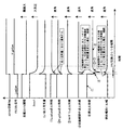
次に、図4は、燃費重視カムから出力重視カムへの切換の際の作用を示すタイミングチャートである。これは、例えば要求トルクの増加により上記の境界線bを横切ったときの切換に相当するが、やはりタイミングチャート中では切換の前後で要求トルクが変化しないものとして示している。
【0036】
上記の境界線bを横切ったときに、スロットル切換タイミング信号が出力され、カムに対応したスロットル弁開度の変更が実行される。具体的には、切換後の出力重視カムで等トルクとなる吸入負圧を目標吸入負圧として、この目標吸入負圧に必要な目標スロットル弁開度が決定される。電子制御スロットル弁18の実際の開度は、この目標スロットル弁開度に沿って減少する。そして、同時に、カム切換信号(VVLソレノイド信号)が出力され、上述したリフト・作動角可変機構のカムの切換が実行される。
【0037】
スロットル弁開度の減少によって、コレクタ16内の吸入負圧は、図示するように徐々に増大する。これに対し、カムは、僅かな応答遅れの後にリフト・作動角の大きな出力重視カムに切り換えられるので、当初は、吸入負圧が目標より弱い状態で出力重視カムにより運転される。そのため、そのままではシリンダ内吸入空気量が過剰でトルクが上昇してしまうので、カム切換に併せて、点火時期のリタードを行い、トルク増加を相殺する。図中にトルクダウン点火時期として示すように、点火時期リタードのリタード量は、切換前後の目標吸入負圧の差によるトルク差に対応した大きさで初期に与えられ、その後、適宜な時定数の一次遅れに沿うように徐々に減少する。これにより、コレクタ16内の実際の吸入負圧の変化に対応したものとなり、最終的に発生するトルクを等トルクに抑制できる。
【0038】
ここで、カム切換信号の出力から前述したVVL切換ばらつき期間の間は、図3の切換例と同様に、切換期間中点火時期として示す中間的な特性の点火時期に補正される。なお、図3の場合と異なり、VVL切換ばらつき期間の間、吸入負圧(Boost)が変化し、これに対応してLowCam点火時期およびHighCam点火時期が変化するので、切換期間中点火時期もこれに沿った特性となる。
【0039】
従って、最終的な目標点火時期としては、スロットル切換タイミング信号の出力までは、燃費重視カムでの要求点火時期に沿ったものとなり、その後のVVL切換ばらつき期間中は、上記の切換期間中点火時期に制御される。その後、シリンダ内吸入空気量が過剰である間は、出力重視カムの要求点火時期にトルクダウン点火時期を加算したものとなり、トルクダウン終了後は、出力重視カムでの要求点火時期に沿った値となる。
【0040】
また、燃料噴射量(燃料噴射パルス幅)についても、VVL切換ばらつき期間中は、出力重視カムでの最適な燃料噴射量と燃費重視カムでの最適な燃料噴射量との間の中間的な値に補正される。特に、いずれのカムでも失火限界を越えないような中間的な値となる。
【0041】
なお、細実線で示す特性は、前述した図3の細実線と同様に、VVL切換ばらつき期間の中で、時間経過に伴って徐々に切換後の要求に近づけるようにした例を示す。
【0042】
以上のような処理により、出力重視カムから燃費重視カムへの切換ならびに燃費重視カムから出力重視カムへの切換の双方において、トルク段差を確実に回避することができるとともに、点火時期および燃料噴射量を、実際のカム切換タイミングのばらつきがあっても運転性の悪化を来さない妥当なものに維持することができる。
【0043】
次に、図5は、上記のような制御を実現するコントロールユニット19の一部の機能を機能ブロック図として示したものであり、カム切換時制御タイミング指令部51は、カム切換の要否を判定するカム切換判定値の入力に基づき、点火時期切換操作指令つまり後述するADV切換フラグ1,2を、それぞれ適宜なタイミングで出力する。カム切換制御時トルクダウンADV制御補正量演算部52は、Boost合わせ制御時目標吸入空気補正量と機関回転速度と位相可変機構の位相(VTC角度)とから、前述したトルクダウン点火時期を求める。なお、Boost合わせ制御時目標吸入空気補正量は、図3に示したBoost合わせ期間中の目標吸入空気補正量であり、図3のシリンダ内吸入空気量と同様の特性となる。HighCam点火時期演算部53は、そのときの運転条件つまり機関回転速度とITAC(シリンダ吸気充填効率)とVTC角度とに基づいて、出力重視カムでの要求点火時期を設定するものである。切換期間中点火時期演算部54は、この出力重視カムでの要求点火時期をベースとして、前述したVVL切換ばらつき期間中の中間的な点火時期を設定する。LowCam点火時期演算部55は、HighCam点火時期演算部53と同様に、そのときの運転条件に基づいて、燃費重視カムでの要求点火時期を設定する。点火時期切換演算部56は、カム切換時制御タイミング指令部51からのタイミング信号に基づいて、前述したような最終的な目標点火時期を決定する。
【0044】
図6は、上記切換期間中点火時期演算部54の詳細を示すブロック図であり、切換期間中点火時期補正マップ61によって、機関回転速度、VTC角度、切換時目標吸入空気量(Boost合わせ制御時目標吸入空気補正量)に基づく、所要の補正量を求める。そして、加算点62において、出力重視カムでの要求点火時期(HighCam点火時期)に、この補正量を加えて、切換期間中点火時期を求める。
【0045】
図7は、上記点火時期切換演算部56の詳細を示すブロック図であり、トルクダウンの開始終了を示すADV切換フラグ1に基づいてブロック71でトルクダウンの要否の判定を行い、ブロック72で、トルクダウン点火時期(点火時期補正量)による補正を行うか否か選択する。加算点73では、この補正量を、HighCam点火時期に加算する。そして、ブロック74では、VVL切換ばらつき期間の開始終了を示すADV切換フラグ2に基づいて、HighCam点火時期(トルクダウン補正を含む)、LowCam点火時期、あるいは切換期間中点火時期のいずれかを選択する。
【0046】
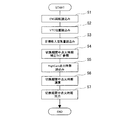
次に図8は、上記の切換期間中点火時期演算部54の処理の流れをフローチャートとして示したものである。まず、機関回転速度とVTC角度と目標吸入空気量とを読み込む(ステップ1,2,3)。ステップ4では、切換期間中点火時期補正マップを参照して補正量を求める。ステップ5で、出力重視カムでの要求点火時期つまりHighCam点火時期を読み込み、ステップ6で、補正量を加算することにより切換期間中の点火時期を求め、ステップ7で、これを出力する。
【0047】
図9は、上記の点火時期切換演算部56の処理の流れをフローチャートとして示したものである。まず、HighCam点火時期を読み込み(ステップ11)、かつトルクダウン期間を示すADV切換フラグ1を読み込む(ステップ12)。そして、ステップ3で、トルクダウンを行う期間か判定し、NOであればステップ16へ進む。トルクダウン期間であれば、トルクダウン点火時期を読み込み(ステップ14)、HighCam点火時期を補正する(ステップ15)。
【0048】
ステップ16では、VVL切換ばらつき期間中であることを示すADV切換フラグ2を読み込み、ステップ17で、HighCam点火時期とする条件か判定する。HighCam点火時期とする期間であれば、ステップ21で、HighCam点火時期(HighCam点火時期そのもの、あるいはトルクダウンのために補正された値)を目標点火時期として出力する。ステップ17でNOであれば、ステップ18で、現在LowCam点火時期であるか判定し、LowCam点火時期であれば、ステップ19へ進んでLowCam点火時期を読み込み、かつステップ21でこれを目標点火時期として出力する。LowCam点火時期でなければ、ステップ20へ進んで切換期間中点火時期を読み込み、ステップ21でこれを目標点火時期として出力する。
【0049】
以上、この発明を、出力重視カムと燃費重視カムとの2つのカムを備えた実施例について説明したが、この発明は、3つ以上のカムを切り換える可変動弁機構についても同様に適用することができる。
【0050】
また上記実施例では、吸気系容積に起因するトルク段差を解消するために、事前のBoost合わせ制御や点火時期リタードによるトルクダウン制御を行っているが、本発明においては、これらの処理は必須のものではない。
【図面の簡単な説明】
【図1】この発明の一実施例を示す内燃機関全体の構成説明図。
【図2】カムの切換領域を示す特性図。
【図3】出力重視カムから燃費重視カムへの切換の際のタイミングチャート。
【図4】燃費重視カムから出力重視カムへの切換の際のタイミングチャート。
【図5】制御装置の要部を示す機能ブロック図。
【図6】切換期間中点火時期演算部の機能ブロック図。
【図7】点火時期切換演算部の機能ブロック図。
【図8】切換期間中点火時期演算部の処理の流れを示すフローチャート。
【図9】点火時期切換演算部の処理の流れを示すフローチャート。
【符号の説明】
2…可変動弁機構
19…エンジンコントロールユニット[0001]
BACKGROUND OF THE INVENTION
The present invention relates to a so-called cam switching type variable valve mechanism, and more particularly to a control device for an internal combustion engine provided with a variable valve mechanism in which the characteristics of each cam are set on the premise of different intake negative pressures.
[0002]
[Prior art]
As a variable valve mechanism on the intake valve side of an internal combustion engine, a so-called cam-switching type variable valve having at least two cams having different valve lift characteristics and selecting these cams to drive the intake valve The mechanism is conventionally known. However, many of the internal combustion engines in practical use use a low speed cam suitable for the engine low speed range and a high speed cam suitable for the engine high speed range, and the torque characteristics (torque curve) by these cams are Under the same negative suction pressure, they have the characteristic of crossing each other at a certain rotational speed. Therefore, when the cam is switched at this intersecting rotational speed, the torque change accompanying the switching is basically small.
[0003]
On the other hand, on the premise that they are used under different suction negative pressures, switch between a fuel efficient cam with a small operating angle suitable for a low load range and an output focused cam with a large operating angle suitable for a high load range. There is what I did. This is used in combination with a so-called electronically controlled throttle valve whose opening degree can be controlled by a control signal from the control unit. The throttle valve opening is controlled so that the pressure is lowered (approaching atmospheric pressure), and as a result, the pumping loss at low load is greatly reduced. In this case, the torque curves by the respective cams under the same suction negative pressure do not cross each other. That is, the cam profile of each cam is greatly different.
[0004]
Therefore, at the boundary between the two, even if the torque and the engine speed are the same, the required ignition timing differs depending on the cam used.
[0005]
Therefore, when switching from one cam to the other, it is necessary to switch the ignition timing at the same time. However, if the timing of switching the ignition timing does not coincide with the actual cam switching, knocking may occur. This affects driving performance, such as hesitation.
[0006]
In order to deal with such a problem of the ignition timing switching, in Japanese Patent Application Laid-Open No. 7-224746, the time until the intake air amount changes after the cam switching command is output is defined as the operating oil temperature. A technique is disclosed in which learning is performed every time, and at the time of cam switching, the ignition timing is switched at the timing when this operation delay time has elapsed after the output of the cam switching command.
[0007]
[Problems to be solved by the invention]
In the above prior art, the time when the intake air amount changes is regarded as the actual cam switching time, but there is a response delay of the change in the air amount due to the volume of the intake system, etc. The accuracy is not always sufficient. For this reason, the operation delay time elapsed time and the actual cam switching time may be slightly deviated, and in this case, the drivability such as knocking or hesitation is deteriorated.
[0008]
In particular, in the configuration in which the cam switching mechanism is provided for each cylinder in the form of a rocker arm, the actual cam switching timing in each cam switching mechanism will be somewhat different. It is not possible to deal with different switching timings.
[0009]
[Means for Solving the Problems]
A control apparatus for an internal combustion engine according to the present invention has at least two cams having different valve lift characteristics, and a variable valve operating mechanism in which a cam switching mechanism for selecting these cams to drive an intake valve is provided for each cylinder. It has a mechanism. Further, an accelerator operation member, for example, a sensor for detecting an operation amount of an accelerator pedal, a throttle valve whose opening degree can be controlled by a control signal, and an ignition timing control means for controlling an ignition timing are provided. At the time of switching, the opening of the throttle valve is controlled so that the intake negative pressure varies depending on each cam, and the ignition timing is controlled to a different required ignition timing depending on each cam.
[0010]
In the present invention, the intermediate timing which does not exceed the allowable ignition timing limit in the cam before switching and the allowable ignition timing in the cam after switching for a predetermined period after the cam switching command is output to the variable valve mechanism. Correct the ignition timing.
[0011]
Specifically, control is temporarily performed to an ignition timing intermediate between the required ignition timing in one cam and the required ignition timing in the other cam.
[0012]
The predetermined period is a period during which cam switching is considered to be completed by all cam switching mechanisms, particularly a period in which variation in switching is taken into consideration. This period may be given as a fixed time, or may be set according to the oil temperature or the like. That is, during this period, it is unclear which cam is actually selected by the plurality of cam switching mechanisms. Therefore, in the present invention, during this period, the ignition timing is controlled to an intermediate value that is a compromise point in which either cam does not greatly affect the drivability. After the elapse of this period, control is performed to the required ignition timing in the cam after switching.
[0013]
【The invention's effect】
According to the control device for an internal combustion engine according to the present invention, even if the actual cam switching timings of the plurality of cam switching mechanisms vary, it is possible to sufficiently suppress the deterioration in drivability such as knocking and hesitation, and with high accuracy. A means for detecting the cam switching timing becomes unnecessary.
[0014]
DETAILED DESCRIPTION OF THE INVENTION
Hereinafter, preferred embodiments of the present invention will be described in detail with reference to the drawings.
[0015]
FIG. 1 shows an embodiment in which the present invention is applied to a V-type 6-cylinder gasoline engine 1, and cam switching type
[0016]
The exhaust manifolds 6 in the left and right banks are connected to a
[0017]
A
[0018]
In order to detect the engine speed and the crank angle position, a
[0019]
In this embodiment, the
[0020]
The variable lift / operating angle mechanism includes, for example, an output-oriented cam with a large lift and operating angle (described in Japanese Patent Application Laid-Open No. 7-224746, Japanese Patent No. 2722815, etc.). High cam) and a low fuel consumption cam with a small lift and operating angle (Low cam) are provided, and as a cam switching mechanism, a main rocker arm that follows the fuel consumption important cam and a sub rocker arm that follows the output important cam, And a hydraulic engagement mechanism that engages and disengages the cylinder. The
[0021]
The phase variable mechanism is a so-called VTC mechanism. As described in JP 2001-280167 A, JP 2002-89303 A, and the like, a crank is provided at the front end of the
[0022]
FIG. 2 shows the characteristics of the cam switching by the lift / operating angle variable mechanism. As shown in the figure, in the low speed / low load side area, the cam becomes a fuel-saving cam with a small lift / small operating angle, And in the high speed range, it becomes an output-oriented cam with a large lift and large operating angle. Appropriate hysteresis is given to each switching, switching from the output-oriented cam to the fuel-oriented cam is a boundary line a in the figure, and switching from the fuel-oriented cam to the output-oriented cam is a boundary line b, Each done. In accordance with the switching of the cam, the suction negative pressure, that is, the throttle valve opening is switched and the ignition timing is switched. In this embodiment, the response delay of the suction negative pressure change due to the intake system volume is taken into consideration. Control is performed so that no torque step is generated.
[0023]
FIG. 3 is a timing chart showing the operation when switching from the output-oriented cam to the fuel-efficient cam. This corresponds to, for example, switching when the boundary line a is crossed due to a decrease in the required torque, but for the sake of easy understanding, this timing chart shows that the required torque does not change before and after the switching. Yes.
[0024]
When the boundary line a is crossed, a throttle switching timing signal is output, and the throttle valve opening corresponding to the cam is changed. Specifically, the target throttle valve opening required for this target suction negative pressure is determined by setting the suction negative pressure that is equal torque in the fuel-consumption emphasis cam after switching to the target suction negative pressure. The actual opening degree of the electronic
[0025]
As the throttle valve opening increases, the suction negative pressure (Boost) in the
[0026]
When a predetermined switching boost adjustment period has elapsed from the output of the throttle switching timing signal, a cam switching signal (VVL solenoid signal) is output, and the switching of the cam of the lift / operating angle variable mechanism described above is executed. The switching boost adjustment period corresponds to a delay time until the actual suction negative pressure in the
[0027]
It should be noted that the target throttle valve opening becomes smaller than that during the boost matching period as shown in the figure as the cam is switched. In other words, as described above, the target throttle valve opening required for this target suction negative pressure is determined by setting the suction negative pressure that is equal to the torque before the switching by the fuel efficiency-oriented cam as the target suction negative pressure. In this case, since the fuel consumption-oriented cam is already operated, the required target throttle valve opening is smaller than that during the boost adjustment period where the output-oriented cam is operated.
[0028]
Here, the delay from the output of the cam switching signal to the actual completion of the cam switching varies depending on various factors, and differs somewhat depending on the cam switching mechanism of each cylinder. A predetermined period, that is, a VVL switching variation period is set. Therefore, the cam switching of the plurality of cam switching mechanisms is completed somewhere in this period, but the actual cam switching timing is not strictly specified. For this reason, within this VVL switching variation period, the ignition timing and the fuel injection amount are corrected to an intermediate value that does not affect the drivability of both cams.
[0029]
In the figure, the LowCam ignition timing indicates the required ignition timing for the fuel-consumption-oriented cam, and the HighCam ignition timing indicates the required ignition timing for the output-oriented cam. Since the intake air amount in the cylinder increases during the boost adjustment period, the ignition timing is retarded accordingly. Even if the torque is equal before and after switching, the fuel consumption-oriented cam reduces the amount of intake air in the cylinder due to reduction of friction and pump loss.
[0030]
The ignition timing during the switching period is the ignition timing during the VVL switching variation period described above. Whichever is the ignition timing allowable limit for the output-oriented cam before switching and the ignition timing allowable limit for the fuel-oriented cam after switching? Is set to an intermediate ignition timing not exceeding. For example, an intermediate ignition timing between the required ignition timing for the output-oriented cam and the required ignition timing for the fuel-efficient cam, or between the ignition timing immediately before the start of cam switching and the required ignition timing after the switching Ignition timing. Alternatively, as will be described later, it is also possible to obtain this by adding a correction according to the operating condition based on the required ignition timing at the output-oriented cam.
[0031]
Therefore, the final target ignition timing is in line with the required ignition timing of the output-oriented cam until the output of the throttle switching timing signal, and the torque down ignition timing is added to this during the subsequent boost adjustment period. Will be. Then, during the VVL switching variation period, the ignition timing is controlled during the switching period, and thereafter, the value is in line with the required ignition timing in the fuel efficiency-oriented cam.
[0032]
The fuel injection amount (fuel injection pulse width) is also an intermediate value between the optimum fuel injection amount in the output-oriented cam and the optimum fuel injection amount in the fuel-efficient cam during the VVL switching variation period. It is corrected to. In particular, it is an intermediate value that does not exceed the misfire limit for any cam.
[0033]
Here, in the above embodiment, the ignition timing during the VVL switching variation period is kept constant, but as shown by the thin solid line in FIG. 3, the ignition timing allowable limit in the output-oriented cam before switching and the switching after switching are changed. Within the range that does not exceed the allowable ignition timing limit for the cam with emphasis on fuel efficiency, the initial timing is close to the required ignition timing with the cam with emphasis on output before switching, and gradually approaches the required ignition timing with the cam with emphasis on fuel efficiency after switching. May be. This takes into account the probability that the actual cam switching has been completed. Even during the VVL switching variation period, the initial probability is that the cam is an output-oriented cam. Since the probability of being operated becomes high, the ignition timing becomes more appropriate for the whole internal combustion engine having a plurality of cylinders. Similarly, as indicated by the thin solid line, the fuel injection amount is within the range not exceeding the misfire limit of the output-oriented cam before switching and the misfire limit of the fuel-oriented cam after switching, and the initial value before switching It is possible to make the output closer to the demand of the cam with emphasis on the output and gradually approach the demand with the cam with emphasis on the fuel efficiency after switching.
[0034]
At the time of shifting to the VVL switching variation period, the suction negative pressure (Boost) has already converged substantially constant.
[0035]
Next, FIG. 4 is a timing chart showing an operation when switching from a fuel-consideration-oriented cam to an output-oriented cam. This corresponds to, for example, switching when the required torque increases and crosses the boundary line b. However, the required torque does not change before and after the switching in the timing chart.
[0036]
When the boundary line b is crossed, a throttle switching timing signal is output, and the throttle valve opening corresponding to the cam is changed. More specifically, the target suction valve opening required for the target suction negative pressure is determined by setting the suction negative pressure that is equal torque in the output-oriented cam after switching as the target suction negative pressure. The actual opening of the electronically controlled
[0037]
As the throttle valve opening decreases, the suction negative pressure in the
[0038]
Here, during the VVL switching variation period from the output of the cam switching signal, the ignition timing is corrected to an intermediate characteristic shown as the ignition timing during the switching period, as in the switching example of FIG. Unlike the case of FIG. 3, the suction negative pressure (Boost) changes during the VVL switching variation period, and the LowCam ignition timing and the HighCam ignition timing change accordingly, so that the ignition timing during the switching period also changes. It becomes the characteristic along.
[0039]
Therefore, the final target ignition timing is in line with the required ignition timing of the fuel efficiency-oriented cam until the output of the throttle switching timing signal, and during the subsequent VVL switching variation period, the ignition timing during the switching period described above. To be controlled. After that, while the intake air amount in the cylinder is excessive, the torque-down ignition timing is added to the required ignition timing of the output-oriented cam, and after the torque reduction is finished, the value according to the required ignition timing of the output-oriented cam It becomes.
[0040]
The fuel injection amount (fuel injection pulse width) is also an intermediate value between the optimum fuel injection amount in the output-oriented cam and the optimum fuel injection amount in the fuel-efficient cam during the VVL switching variation period. It is corrected to. In particular, it is an intermediate value that does not exceed the misfire limit for any cam.
[0041]
The characteristic indicated by the thin solid line shows an example in which, as with the thin solid line in FIG. 3 described above, within the VVL switching variation period, it gradually approaches the request after switching as time elapses.
[0042]
With the above processing, torque steps can be reliably avoided in both the switching from the output-oriented cam to the fuel-oriented cam and the switching from the fuel-oriented cam to the output-oriented cam, and the ignition timing and fuel injection amount can be avoided. Can be maintained at a reasonable level that does not deteriorate the drivability even if there is a variation in the actual cam switching timing.
[0043]
Next, FIG. 5 is a functional block diagram showing a part of the function of the
[0044]
FIG. 6 is a block diagram showing details of the ignition timing
[0045]
FIG. 7 is a block diagram showing the details of the ignition timing switching
[0046]
Next, FIG. 8 is a flowchart showing the processing flow of the ignition timing
[0047]
FIG. 9 is a flowchart showing the processing flow of the ignition timing switching
[0048]
In
[0049]
Although the present invention has been described with respect to the embodiment provided with two cams, namely, the output-oriented cam and the fuel efficiency-oriented cam, the present invention is similarly applied to a variable valve mechanism that switches three or more cams. Can do.
[0050]
Further, in the above embodiment, in order to eliminate the torque step caused by the intake system volume, the prior boost adjustment control and the torque down control by the ignition timing retard are performed. However, in the present invention, these processes are indispensable. It is not a thing.
[Brief description of the drawings]
FIG. 1 is an explanatory diagram of the configuration of an entire internal combustion engine according to an embodiment of the present invention.
FIG. 2 is a characteristic diagram showing a switching region of a cam.
FIG. 3 is a timing chart when switching from an output-oriented cam to a fuel-efficient cam.
FIG. 4 is a timing chart at the time of switching from a fuel efficiency-oriented cam to an output-oriented cam.
FIG. 5 is a functional block diagram showing a main part of the control device.
FIG. 6 is a functional block diagram of an ignition timing calculation unit during a switching period.
FIG. 7 is a functional block diagram of an ignition timing switching calculation unit.
FIG. 8 is a flowchart showing a processing flow of an ignition timing calculation unit during a switching period.
FIG. 9 is a flowchart showing a processing flow of an ignition timing switching calculation unit.
[Explanation of symbols]
2 ...
Claims (5)
大リフト・大作動角の出力重視カムから小リフト・小作動角の燃費重視カムへのカム切換時には、カム切換指令の出力前に、スロットル弁開度を増加するとともに、このスロットル弁開度の増加による吸入負圧の低下に応じて点火時期のリタード制御を行い、
かつ、上記可変動弁機構にカム切換指令が出力されてから所定の期間、切換前のカムでの点火時期許容限界および切換後のカムでの点火時期許容限界を越えない中間的な点火時期であって、かつ、カム切換開始直前の点火時期と切換後のカムでの要求点火時期との中間の点火時期に制御することを特徴とする内燃機関の制御装置。It has at least two cams with different valve lift characteristics, and a cam switching mechanism that selects these cams to drive the intake valve and detects the amount of operation of the accelerator operation member. And a throttle valve whose opening degree can be controlled by a control signal, and an ignition timing control means for controlling the ignition timing, and when switching the cam, the intake negative pressure varies depending on each cam. In the control device for an internal combustion engine that controls the opening degree of the throttle valve and controls the ignition timing to a different required ignition timing for each cam,
When switching from a cam with a large lift / large operating angle to a cam with a small lift / small operating angle, the throttle valve opening is increased before the cam switching command is output. The ignition timing is retarded according to the decrease in suction negative pressure due to the increase,
In addition, an intermediate ignition timing that does not exceed the allowable ignition timing limit for the cam before switching and the allowable ignition timing for the cam after switching for a predetermined period after the cam switching command is output to the variable valve mechanism. A control device for an internal combustion engine, wherein the control is performed to an ignition timing intermediate between the ignition timing immediately before the start of cam switching and the required ignition timing at the cam after switching .
小リフト・小作動角の燃費重視カムから大リフト・大作動角の出力重視カムへのカム切換時には、カム切換指令と同時に、スロットル開度を低下するとともに、点火時期のリタード制御を行い、
かつ、上記可変動弁機構にカム切換指令が出力されてから所定の期間、切換前のカムでの点火時期許容限界および切換後のカムでの点火時期許容限界を越えない中間的な点火時期であって、かつ、カム切換開始直前の点火時期と切換後のカムでの要求点火時期との中間の点火時期に制御することを特徴とする内燃機関の制御装置。 It has at least two cams with different valve lift characteristics, and a cam switching mechanism that selects these cams to drive the intake valve and detects the amount of operation of the accelerator operation member. And a throttle valve whose opening degree can be controlled by a control signal, and an ignition timing control means for controlling the ignition timing, and when switching the cam, the intake negative pressure varies depending on each cam. In the control device for an internal combustion engine that controls the opening degree of the throttle valve and controls the ignition timing to a different required ignition timing for each cam,
When switching from a small lift / small working angle fuel-efficient cam to a large lift / large operating angle output-oriented cam, simultaneously with the cam switching command, the throttle opening is reduced and the ignition timing is retarded.
In addition, an intermediate ignition timing that does not exceed the allowable ignition timing limit for the cam before switching and the allowable ignition timing for the cam after switching for a predetermined period after the cam switching command is output to the variable valve mechanism. A control device for an internal combustion engine, wherein the control is performed to an ignition timing intermediate between the ignition timing immediately before the start of cam switching and the required ignition timing at the cam after switching .
Priority Applications (1)
| Application Number | Priority Date | Filing Date | Title |
|---|---|---|---|
| JP2002262535A JP3975868B2 (en) | 2002-09-09 | 2002-09-09 | Control device for internal combustion engine |
Applications Claiming Priority (1)
| Application Number | Priority Date | Filing Date | Title |
|---|---|---|---|
| JP2002262535A JP3975868B2 (en) | 2002-09-09 | 2002-09-09 | Control device for internal combustion engine |
Publications (2)
| Publication Number | Publication Date |
|---|---|
| JP2004100547A JP2004100547A (en) | 2004-04-02 |
| JP3975868B2 true JP3975868B2 (en) | 2007-09-12 |
Family
ID=32262554
Family Applications (1)
| Application Number | Title | Priority Date | Filing Date |
|---|---|---|---|
| JP2002262535A Expired - Fee Related JP3975868B2 (en) | 2002-09-09 | 2002-09-09 | Control device for internal combustion engine |
Country Status (1)
| Country | Link |
|---|---|
| JP (1) | JP3975868B2 (en) |
Families Citing this family (4)
| Publication number | Priority date | Publication date | Assignee | Title |
|---|---|---|---|---|
| JP4896417B2 (en) * | 2005-03-22 | 2012-03-14 | 株式会社デンソー | Control device for internal combustion engine |
| JP4605037B2 (en) * | 2006-02-01 | 2011-01-05 | 株式会社デンソー | Control device |
| JP6003242B2 (en) | 2012-05-31 | 2016-10-05 | スズキ株式会社 | Control device for internal combustion engine |
| EP4166777A4 (en) * | 2020-06-12 | 2023-07-26 | Nissan Motor Co., Ltd. | Engine control method and engine control device |
-
2002
- 2002-09-09 JP JP2002262535A patent/JP3975868B2/en not_active Expired - Fee Related
Also Published As
| Publication number | Publication date |
|---|---|
| JP2004100547A (en) | 2004-04-02 |
Similar Documents
| Publication | Publication Date | Title |
|---|---|---|
| EP1848885B1 (en) | Control method and control apparatus for internal combustion engine | |
| US6779508B2 (en) | Control system of internal combustion engine | |
| JP3011070B2 (en) | Intake air amount detection device for internal combustion engine with continuously variable valve timing mechanism | |
| JP2001050090A (en) | Intake air volume calculation system for variable valve timing engine | |
| US10480434B2 (en) | Control device for internal combustion engine | |
| US7328673B2 (en) | Valve timing correction control apparatus and method for an internal combustion engine | |
| JP3873834B2 (en) | Intake valve drive control device for internal combustion engine | |
| JP4036057B2 (en) | Intake valve drive control device for internal combustion engine | |
| JP3975868B2 (en) | Control device for internal combustion engine | |
| JP4019866B2 (en) | Control device for internal combustion engine | |
| JP4000747B2 (en) | Ignition timing control device for variable valve engine | |
| JP2001159386A (en) | Ignition timing control device for variable valve system engine | |
| JP4003567B2 (en) | Intake control device for internal combustion engine | |
| JP4053634B2 (en) | DOHC engine variable valve timing system | |
| JP2019060311A (en) | Control device for internal combustion engine, and control method for internal combustion engine | |
| JPH0849577A (en) | Intake air controller of internal combustion engine | |
| JP3933007B2 (en) | Intake control device for internal combustion engine | |
| JP3915367B2 (en) | Control device for variable valve engine | |
| JP5085597B2 (en) | Engine control device | |
| JP4438575B2 (en) | Ignition timing control device for internal combustion engine | |
| JP2004124743A (en) | Control device for internal combustion engine | |
| JP2005133622A (en) | Control device for internal combustion engine | |
| JP2010229911A (en) | Control device for variable valve train | |
| JP3758448B2 (en) | Control device for variable valve engine | |
| JP4760793B2 (en) | Control device for internal combustion engine |
Legal Events
| Date | Code | Title | Description |
|---|---|---|---|
| A621 | Written request for application examination |
Free format text: JAPANESE INTERMEDIATE CODE: A621 Effective date: 20050624 |
|
| A977 | Report on retrieval |
Free format text: JAPANESE INTERMEDIATE CODE: A971007 Effective date: 20070112 |
|
| A131 | Notification of reasons for refusal |
Free format text: JAPANESE INTERMEDIATE CODE: A131 Effective date: 20070227 |
|
| A521 | Written amendment |
Free format text: JAPANESE INTERMEDIATE CODE: A523 Effective date: 20070501 |
|
| TRDD | Decision of grant or rejection written | ||
| A01 | Written decision to grant a patent or to grant a registration (utility model) |
Free format text: JAPANESE INTERMEDIATE CODE: A01 Effective date: 20070529 |
|
| A61 | First payment of annual fees (during grant procedure) |
Free format text: JAPANESE INTERMEDIATE CODE: A61 Effective date: 20070611 |
|
| FPAY | Renewal fee payment (event date is renewal date of database) |
Free format text: PAYMENT UNTIL: 20100629 Year of fee payment: 3 |
|
| R150 | Certificate of patent or registration of utility model |
Free format text: JAPANESE INTERMEDIATE CODE: R150 |
|
| FPAY | Renewal fee payment (event date is renewal date of database) |
Free format text: PAYMENT UNTIL: 20110629 Year of fee payment: 4 |
|
| FPAY | Renewal fee payment (event date is renewal date of database) |
Free format text: PAYMENT UNTIL: 20120629 Year of fee payment: 5 |
|
| FPAY | Renewal fee payment (event date is renewal date of database) |
Free format text: PAYMENT UNTIL: 20120629 Year of fee payment: 5 |
|
| FPAY | Renewal fee payment (event date is renewal date of database) |
Free format text: PAYMENT UNTIL: 20130629 Year of fee payment: 6 |
|
| LAPS | Cancellation because of no payment of annual fees |